
Tiger 7000s - Grinder SCHEPPACH - Free user manual and instructions
Find the device manual for free Tiger 7000s SCHEPPACH in PDF.
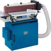
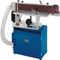
| Product type | Table router (router) |
| Brand | Scheppach |
| Model | Tiger 7000s |
| Dimensions (L x W x H) | 1030 x 360 x 311 mm |
| Table dimensions (L x W) | 610 x 360 mm |
| Table height | 311 mm |
| Weight | 21 kg |
| Power supply | 230-240 V~ / 50 Hz |
| Power consumption | 1500 W |
| Spindle speed range | 11500 - 24000 min⁻¹ (6 levels) |
| Spindle height adjustment | 0 - 40 mm |
| Max. cutter diameter | 50 mm |
| Mounting rings in table | ∅ 32 / 47.5 / 55 / 75 mm |
| Protection rating | IP20 |
| Protection class | I |
| Machining capabilities | Groove milling, recess shaping, copying curves and logos |
| Safety | Overload switch, protective cover, pressure devices, emergency stop via switch |
| Maintenance and cleaning | Regular cleaning with a damp cloth and black soap; check tightening of connections before each use |
| Wear parts | Carbon brushes, cutter |
| Repairability | Electrical repairs reserved for a qualified electrician; spare parts available from customer service |
| Included equipment | Table extensions, router fence, pressure bar, protective cover, suction adapter, mounting tools |
Frequently Asked Questions - Tiger 7000s SCHEPPACH
User questions about Tiger 7000s SCHEPPACH
0 question about this device. Answer the ones you know or ask your own.
Ask a new question about this device
Download the instructions for your Grinder in PDF format for free! Find your manual Tiger 7000s - SCHEPPACH and take your electronic device back in hand. On this page are published all the documents necessary for the use of your device. Tiger 7000s by SCHEPPACH.
USER MANUAL Tiger 7000s SCHEPPACH
natural_image
Industrial machine labeled 'scheppach' with mechanical components and mounting base (no readable text beyond label)
HF60
| DE | TischfräsmaschineOriginalbedienungsanleitung | 8 |
| GB | Table routerTranslation of original instruction manual | 24 |
| FR | DéfonceuseTraduction des instructions d'origine | 37 |
| IT | Fresatrice da bancoLa traduzione dal manuale di istruzioni originale | 51 |
| NL | TafelfreesmachineVertaling van de originele gebruikshandleiding | 65 |
| ES | Fresadora de mesaTraducción del manual de instrucciones original | 79 |
| PT | Fresadora de mesaTradução do manual de operação original | 93 |
| CZ | Stolová frézkaPřeklad originálního návodu k obsluze | 107 |
| SK | Stolová frézkaPreklad originálneho návodu na obsluhu | 120 |
| HU | Asztalos marógépEredeti használati utasítás fordítása | 133 |
| PL | Frezarka stołowadolnowrzecionowaTłumaczenie oryginalnej instrukcji obsługi | 147 |
| HR | Stolna glodalicaPrijevod originalnog priručnika za uporabu | 161 |
| SI | Namizni rezkalni strojPrevod originalnih navodil za uporabo | 174 |
| EE | laudfreesimismasinOriginaalkäitusjuhendi tõlge | 187 |
| LT | Stalinës frezavimo staklësOriginalios naudojimo instrukcijos vertimas | 200 |
| LV | Galda frēzmašīnaOriginālās lietošanas instrukcijas tulkojums | 213 |
| SE | BordsfräsÖversättning av original-bruksanvisning | 226 |
| FI | pöytäjyrsinkoneKäännös alkuperäisestä käyttöohjeesta | 239 |
| DK | BordfræsemaskineOversættelse fra den oprindelige betjeningsvejledning | 252 |
| NO | BordfresemaskinOversettelse av den originale brukerveiledningen | 265 |
| BG | Настолна фрезаПревод на оригиналното ръководство за експлоатация | 278 |
| GR | Фрéζα πάγκουΜετάφραση του πρωτοτύπου των οδηγιών χρήσης | 293 |
| RO | Maşină de frezat de bancTraducere din manualul de exploatare original | 308 |
| RS | Stona glodalicaPrevod originalnog uputstva za upotrebu | 322 |
| TR | Tezgahlı freze makinesiOrijinal kullanım talimatı çevirisi | 335 |


natural_image
Mechanical device with three mounted sensors and a central hub (no visible text or symbols)
natural_image
Mechanical component with mounting holes and a central ventilation grille, labeled with number 15 and page number 3 (no text or symbols on the main subject)

natural_image
Close-up of a gloved hand holding a mechanical component with a numbered label '14' pointing to it, no readable text or symbols present.
natural_image
Close-up of a mechanical component with a propeller and circular opening, labeled with number 15 (no text or symbols beyond labels)
natural_image
Mechanical assembly with two white arrows pointing to a component, no visible text or symbols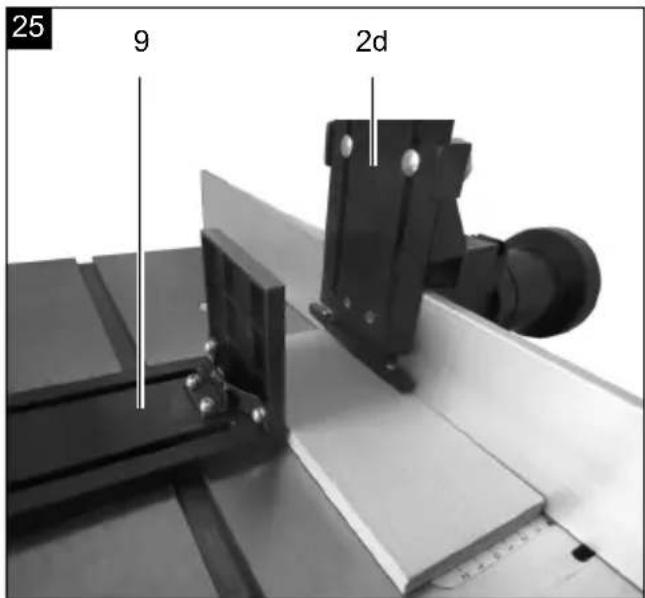
28
| ∅ [mm] | [min-1] | ||
 | 4 - 10 mm | 21000 - 24000 | 5 - 6 |
| 12 - 20 mm | 15500 - 21000 | 3 - 5 | |
| 22 - 40 mm | 11500 - 13000 | 1 - 2 | |
 | 4 - 10 mm | 21000 - 24000 | 5 - 6 |
| 12 - 20 mm | 15500 - 24000 | 3 - 6 | |
| 22 - 40 mm | 11500 - 16000 | 1 - 3 | |
Günzburger Straße 69
D-89335 Ichenhausen
Verehrter Kunde
Homepage: https://www.scheppach.com/de/service
Explanation of the symbols on the device
Symbols are used in this manual to draw your attention to potential hazards. The safety symbols and the accompanying explanations must be fully understood. The warnings themselves will not rectify a hazard and cannot replace proper accident prevention measures.
 | Warning - read the instruction manual to reduce the risk of injury. |
 | Wear hearing protection. Excessive noise can result in a loss of hearing. |
 | Wear a dust protection mask. When machining wood and other materials, harmful dust may be generated. Do not machine material containing asbestos! |
 | Wear eye protection. Sparks created during work or fragments, chippings and dust ejected by the device can case sight loss. |
 | Pay attention to the feed direction! |
 | Hard wood (beech, oak) |
 | Soft wood (spruce, pine) |
| ⚠ Attention! | We have marked points in these operating instructions that impact your safety with this symbol. |
 | The product complies with the applicable European directives. |
 | The product complies with the applicable Serbian directives. |
Table of contents: Page:
- Introduction....26
- Device description (Fig. 1)....26
- Scope of delivery 26
- Proper use 27
- General safety instructions.... 27
- Residual risks 29
- Technical data....30
- Unpacking....30
- Layout 30
- Start up 32
- Operation 33
- Electrical connection 34
- Cleaning 34
- Storage 34
- Maintenance 35
- Disposal and recycling....35
- Troubleshooting 36
- Declaration of conformity 349
1. Introduction
Manufacturer:
Scheppach GmbH
Günzburger Straße 69
D-89335 Ichenhausen
Dear Customer
We hope your new tool brings you much enjoyment and success.
Note:
In accordance with the applicable product liability laws, the manufacturer of this device assumes no liability for damage to the device or caused by the device arising from:
- Improper handling
- Failure to comply with the operating manual,
- Repairs carried out by third parties, unauthorised specialists
• Installing and replacing non-original spare parts, - Improper use
- Failures of the electrical system in the event of the electrical regulations and VDE provisions 0100, DIN 57113 / VDE 0113 not being observed
Note:
Read the whole text of the operating manual before assembly and commissioning.
This operating manual should help you to familiarise yourself with your device and to use it for its intended purpose.
The operating manual includes important instructions for safe, proper and economic operation of the device, for avoiding danger, for minimising repair costs and downtimes, and for increasing the reliability and extending the service life of the device.
In addition to the safety instructions in this operating manual, you must also observe the regulations applicable to the operation of the device in your country.
Keep the operating manual at the device, in a plastic sleeve, protected from dirt and moisture. They must be read and carefully observed by all operating personnel before starting the work.
The device may only be used by personnel who have been trained to use it and who have been instructed with respect to the associated hazards.
The required minimum age must be observed.
In addition to the safety instructions in this operating manual and the separate regulations of your country, the generally recognised technical rules relating to the operation of such machines must also be observed.
We accept no liability for accidents or damage that occur due to a failure to observe this manual and the safety instructions.
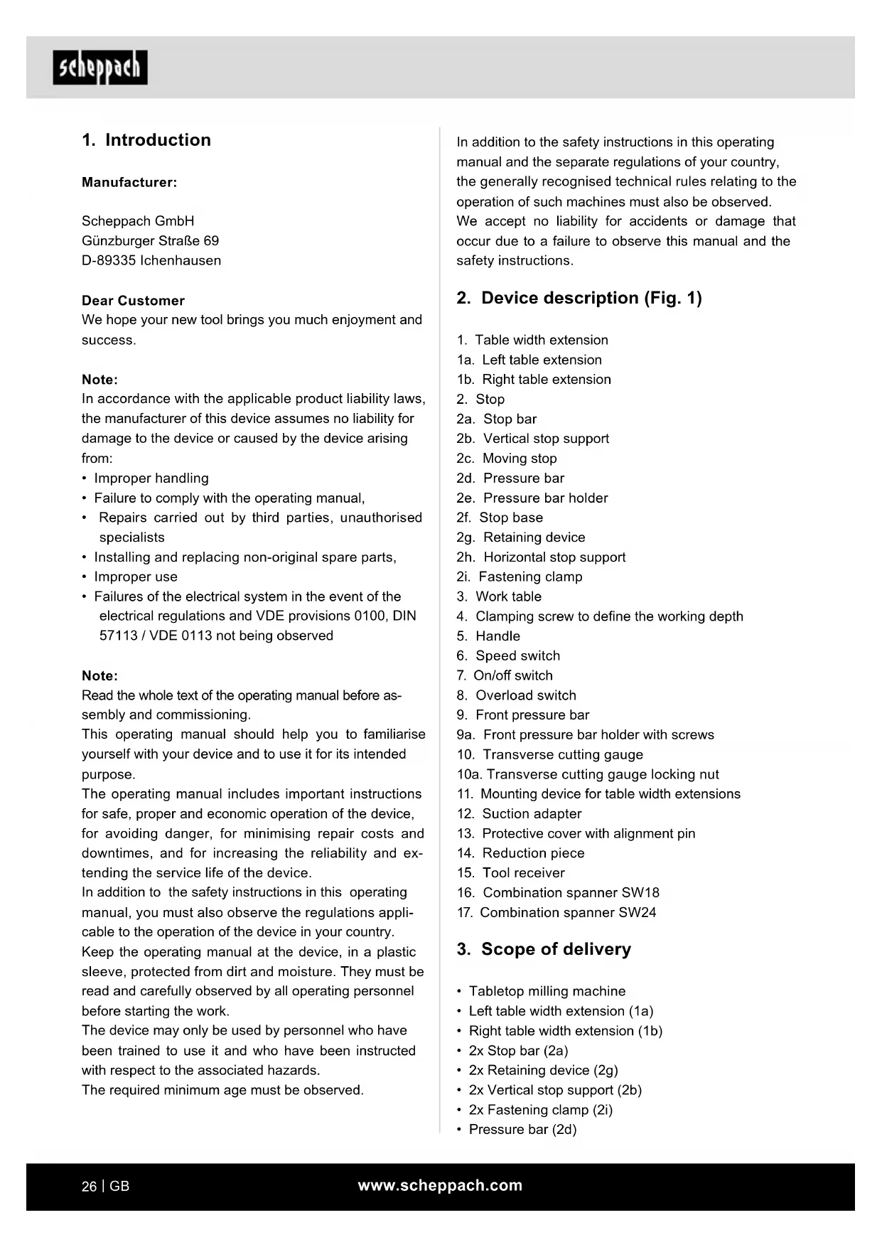
2. Device description (Fig. 1)
- Table width extension
1a. Left table extension
1b. Right table extension - Stop
2a. Stop bar
2b. Vertical stop support
2c. Moving stop
2d. Pressure bar
2e. Pressure bar holder
2f. Stop base
2g. Retaining device
2h. Horizontal stop support
2i. Fastening clamp - Work table
- Clamping screw to define the working depth
- Handle
- Speed switch
- On/off switch
- Overload switch
- Front pressure bar
9a. Front pressure bar holder with screws - Transverse cutting gauge
10a. Transverse cutting gauge locking nut - Mounting device for table width extensions
- Suction adapter
- Protective cover with alignment pin
- Reduction piece
- Tool receiver
- Combination spanner SW18
- Combination spanner SW24
3. Scope of delivery
- Tabletop milling machine
- Left table width extension (1a)
• Right table width extension (1b) - 2x Stop bar (2a)
• 2x Retaining device (2g)
• 2x Vertical stop support (2b)
• 2x Fastening clamp (2i) - Pressure bar (2d)
• Pressure bar holder (2e)
• 2x Horizontal stop support (2h)
- Moving stop (2c)
- Stop base body (2f)
- Front pressure bar (9)
- Front pressure bar holder with screws (9a)
- Suction adapter (12)
- 2x Wooden push block
• Transverse cutting gauge (10)
- Protective cover with alignment pin (13)
- 8x Hexagonal socket screw M5 x 20 (m)
- 6x Hexagonal socket screw M5 x 12 (I)
• 2x Hexagonal socket screw M6 x 16 (g)
• 2x Hexagonal bolt M6 x 40 (c)
- 7x Coach bolt M6 x 20 (f)
• 3x Coach bolt M6 x 25 (d)
- 5x Coach bolt M6 x 35 (e)
• 2x Knurled screw M6 (a)
- 17x Washer ∅ 6 (h)
• 14x Washer ∅ 5 (n)
• 13x Knurled nut M6 (b)
- 2x Wing nut M6 (i)
- 2x Nut M6 (j)
- 8x Nut M5 (o)
- Allen key - size 4 (k)
• Combination spanner SW18
• Combination spanner SW24
• Table width extension mounting device (11)
• Tool receiver ∅ 6 / 8 / 12
- Operating manual
- Allen key - size 5 (p)
4. Proper use
The machine is only intended for the following activities: processing wood and plastic materials, such as: milling grooves, working out recesses, copying curves and lettering within the specified machine limits. The milling machine must not be used for working on metal, stone, etc.
The machine may only be used in the intended manner. Any use beyond this is improper. The user/operator, not the manufacturer, is responsible for damages or injuries of any type resulting from this.
An element of the intended use is also the observance of the safety instructions, as well as the assembly instructions and operating information in the operating manual.
Persons who operate and maintain the machine must be familiar with it and must be informed about potential dangers.
In addition, the applicable accident prevention regulations must be strictly observed.
Other general occupational health and safety-related rules and regulations must be observed.
The liability of the manufacturer and resulting damages are excluded in the event of modifications of the machine.
The machine may only be operated with original parts and original accessories from the manufacturer.
The safety, operating and maintenance specifications of the manufacturer, as well as the dimensions specified in the technical data, must be observed.
Please note that our equipment was not designed with the intention of use for commercial or industrial purposes. We assume no guarantee if the device is used in commercial or industrial applications, or for equivalent work.
The device is intended for use by adults. Children under the age of 16 may only use the device when supervised. The manufacturer is not liable for damage caused by improper use or incorrect operation.
Only use the device as described and for the specified areas of application. The device is not designed for commercial use. Any other use or modification shall be deemed to be improper use and could give rise to considerable risk of accident. The manufacturer assumes no liability for damage arising from inappropriate use.
5. General safety instructions
Attention! The following basic safety measures must be observed when using electric tools for protection against electric shock, and the risk of injury and fire. Read all these notices before using the electric tool and store the safety instructions well for later reference.
Safe work
1 Keep the work area orderly - Disorder in the work area can lead to accidents.
2 Take environmental influences into account - Do not expose electric tools to rain. - Do not use electric tools in a damp or wet environment. - Make sure that the work area is well-illuminated. - Do not use electric tools where there is a risk of fire or explosion.
3 Protect yourself from electric shock - Avoid physical contact with earthed parts (e.g. pipes, radiators, electric ranges, cooling units).
4 Keep other persons away.
- Do not allow other persons, especially children, to touch the electric tool or the cable. Keep them away from your work area.
5 Securely store unused electric tools
– Unused electric tools should be stored in a dry, elevated or closed location out of the reach of children.
6 Do not overload your electric tool
– They work better and more safely in the specified output range.
7 Use the correct electric tool
- Do not use low-output power tools for heavy work.
- Do not use the electric tool for purposes for which it is not intended. For example, do not use handheld circular saws for the cutting of branches or logs.
8 Wear suitable clothing
- Do not wear wide clothing or jewellery, which can become entangled in moving parts.
- When working outdoors, anti-slip footwear is recommended.
– Tie long hair back in a hair net.
9 Use protective equipment
- Wear protective goggles.
- Wear a mask when carrying out dust-creating work.
10 Connect the dust extraction device if you will be processing wood, materials similar to wood, or plastics.
- If connections for dust extraction and a collecting device are present, make sure that they are connected and used properly.
- When processing wood, materials similar to wood, and plastics. operation in enclosed spaces is only permitted with the use of a suitable extraction system.
11 Do not use the cable for purposes for which it is not intended
- Do not use the cable to pull the plug out of the outlet. Protect the cable from heat, oil and sharp edges.
12 Secure the workpiece
- Use the clamping devices or a vice to hold the workpiece in place. It is thus held more securely than with your hand and allows the machine to be operated with both hands.
- An additional support is necessary for long workpieces (table, trestle, etc.) in order to prevent the machine from tipping over.
- Always press the workpiece firmly against the working plate and stop in order to prevent bouncing and twisting of the workpiece.
13 Avoid abnormal posture
- Make sure that you have secure footing and always maintain your balance.
- Avoid awkward hand positions in which a sudden slip could cause one or both hands to come into contact with the cutter.
14 Take care of your tools
- Keep cutting tools sharp and clean in order to be able to work better and more safely.
– Follow the instructions for lubrication and for tool replacement.
- Check the connection cable of the electric tool regularly and have it replaced by a recognised specialist when damaged.
- Check extension cables regularly and replace them when damaged.
- Keep the handle dry, clean and free of oil and grease.
15 Pull the connector out of the socket
- Never remove loose fragments chips or jammed wood pieces from the running cutter.
- When the electric tool is not in use or prior to maintenance and when replacing tools such as saw blades, bits, milling heads.
- If the cutter jams during cutting due to excessive feeding force, switch off the device and disconnect it from the mains.
- Remove the workpiece and make sure that the cutter runs freely. Switch the device on and carry out the cutting operation again with reduced feeding force.
16 Do not leave a tool key inserted
- Before switching on, make sure that keys and adjusting tools are removed.
17 Avoid inadvertent starting
- Make sure that the switch is switched off when plugging the plug into an outlet.
18 Use extension cables for outdoors
- Only use approved and appropriately identified extension cables for use outdoors.
- Only use cable reels in the unrolled state.
19 Remain attentive at all times
- Pay attention to what you are doing. Remain sensible when working. Do not use the electric tool when you are distracted.
20 Check the electric tool for potential damage
- Protective devices or other parts with minor damage must be carefully inspected to ensure that they function correctly and as intended prior to continued use of the electric tool.
- Check whether the moving parts function faultlessly and do not jam or whether parts are damaged. All parts must be correctly mounted and all conditions must be fulfilled to ensure fault-free operation of the electric tool.
– Damaged protective devices and parts must be properly repaired or replaced by a recognised workshop, insofar as nothing different is specified in the operating manual.
– Damaged switches must be replaced at a customer service workshop.
- Do not use any faulty or damaged connection cables.
- Do not use any electric tool on which the switch cannot be switched on and off.
21 ATTENTION!
- The use of other insertion tools and other accessories can entail a danger of injury.
22 Have your electric tool repaired by a qualified electrician
- This electric tool conforms to the applicable safety regulations. Repairs may only be performed by an electrician using original spare parts. Otherwise accidents can occur.
The operator must always stand in front of the machine to avoid danger.
Warning! This power tool generates an electromagnetic field during operation. This field can impair active or passive medical implants under certain conditions. In order to prevent the risk of serious or deadly injuries, we recommend that persons with medical implants consult with their physician and the manufacturer of the medical implant prior to operating the power tool.
ADDITIONAL SAFETY INSTRUCTIONS
- Check that the milling unit is in a faultless condition before use.
- Use table insert rings appropriate for the size of the milling unit.
• Always wear suitable personal protective equipment. This includes:
- Hearing protection to avoid the risk of becoming hearing impaired.
- Respiratory protection to avoid the risk of inhaling harmful dust.
- Possibility of injury when handling the cutting unit and rough materials due to sharp edges. Safety goggles to avoid eye injuries due to ejected parts.
- When working with wood, the operator must be informed of the conditions that affect the release of dust, e.g. the type of material to be processed, the significance of local separation (collection or source) and the correct setting of the hood/guide plates/guides.
- Warning! Do not use milling tools that have not been recommended, because this can lead to injuries with a loss of control. Only use milling tools designed for manual advance and marked with MAN (manual advance) in accordance with EN 847-1.
- Dangerous situation caused by the uncontrolled tilting of the workpiece. Support long workpieces sufficiently to hold their position.
- Possible rebound, a sudden reaction due to the guide for a small workpiece being out of control. Use additional equipment, such as horizontal pressure devices, when processing narrow workpieces.
- Tools that have not been maintained can trigger uncontrollable situations. Only use sharp, maintained milling tools in accordance with the tool manufacturer's specifications.
- Possible contact with moving parts. Before changing or adjusting, switch off the machine and unplug the power plug.
- Possible error when positioning the milling tool. Correctly insert the milling tool in the machine. Slide the workpiece forwards against the rotational direction of the spindle.
- Select a rotational speed that is suitable for the milling tool and material used.
- Keep hands away when milling at the stop. Use pressure devices (pressure shoes) together with the stop if possible.
- Missing lateral stops can result in a rebound. During insertion milling, use rear and/or front lateral stops, which are fastened to the fence.
6. Residual risks
The machine has been built according to the state-of-the-art and the recognised technical safety requirements. However, individual residual risks can arise during operation.
• Health hazard due to electrical power, with the use of improper electrical connection cables.
• Furthermore, despite all precautions having been met, some non-obvious residual risks may still remain.
- Residual risks can be minimised if the "Safety Instructions" and the "Intended Use" together with the operating manual as a whole are observed.
- Avoid accidental starting of the machine: the operating button may not be pressed when inserting the plug in an outlet. Use the tool that is recommended in this operating manual. This is how to ensure that your machine provides optimum performance.
- Keep your hands away from the working area when the machine is in operation.
7. Technical data
Dimensions L x W x H 1030 x 360 x 311 mm
| Table size L x W 610 x 360 mm | |
| Table height 311 mm | |
| Table width extension dimensions L x W | 210 x 360 mm |
| Height adjustment spindle 0 - 40 mm | |
| Table insert rings ∅ 32 / 47,5 / 55 / 75 mm | |
| Spindle speed | 11,500 - 24,000 rpm |
| Max. cutter ∅ | ∅ 50 mm |
| Weight | 21 kg |
| Engine | 230 - 240 V~ / 50 Hz |
| Rated input | 1500 W |
| Protection category | IP20 |
| Protection class | I |
Technical changes reserved!
Noise and vibration
⚠ Warning: Noise can have serious effects on your health. If the machine noise exceeds 85 dB, please wear suitable hearing protection.
Noise data
The noise levels have been determined in accordance with EN 61029.
| Sound power level L_WA | 102 dB |
| Sound pressure level L_pA | 89 dB |
| Uncertainty K_wa/pA | 3 dB |
8. Unpacking
- Open the packaging and carefully remove the device.
- Remove the packaging material, as well as the packaging and transport safety devices (if present).
- Check whether the scope of delivery is complete.
- Check the device and accessory parts for transport damage. In the event of complaints the carrier must be informed immediately. Later claims will not be recognised.
- If possible, keep the packaging until the expiry of the warranty period.
- Familiarise yourself with the product by means of the operating instructions before using for the first time.
- With accessories as well as wearing parts and replacement parts use only original parts. Replacement parts can be obtained from your dealer.
- When ordering please provide our article number as well as type and year of manufacture for your equipment.
⚠ WARNING!
The device and the packaging material are not children's toys! Do not let children play with plastic bags, films or small parts! There is a danger of choking or suffocating!
9. Layout
Attention:
Disconnect the mains plug before carrying out any adjustment or maintenance work.
Fastening the machine
For use, it is recommended to fix the machine on a workbench by means of the four holes.
1 The mounting surface must be pre-drilled, taking into account the spacing of the two mounting holes in the frame.
2 Each attachment point must be tightened securely using screws (not supplied).
3 The screws must be long enough: Take the thickness of the work surface into account on which the machine is mounted.
4 Use the washers and screw to the work surface with the nuts.
5 The work surface must be large enough to prevent the unit from tilting during work.
Parts for table width extension (Fig. 2)
• Left table width extension (1a)
• Right table width extension (1b)
• Table width extension mounting device (11)
- 6x Hexagonal socket screw M5 x 12 (l)
- 8x Hexagonal socket screw M5 x 20 (m)
• 14x Washer ∅ 5 (n)
- 8x Nut M5 (o)
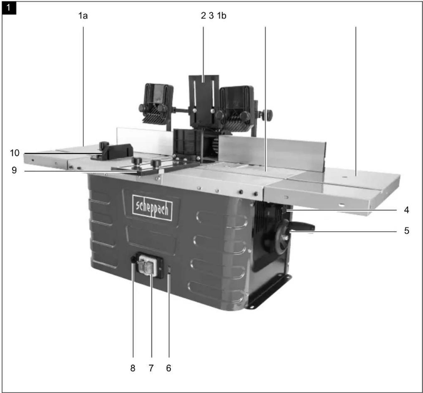
Installing the table width extensions (Fig. 3)
The table width extensions (1) enlarge the table surface and thus enable the machining of large workpieces and the execution of special milling operations.
- Table extensions (1a + 1b) on both sides with 4 Allen screws M5 x 20 (m), 4 washers ∅ 5 (n) and 4 hexagon nuts M5 (o) on each side and with 3 Allen screws M5 x 12 (l) and 3 washers ∅ 5 (n) on the front of the work table (3).
- Push the table width extension mounting device (11) into the groove until it rests on the left table width extension (1a) or the right table width extension (1b) and the work table (4).
- Tighten the table width extension mounting device (11).
- Tighten all screw connections firmly.
- Repeat the process on the other side.
Parts for cutter stop (Fig. 4)
- 2x Stop bar (2a)
• 2x Retaining device (2g)
• 2x Vertical stop support (2b) - 2x Fastening clamp (2i)
- Pressure bar (2d)
• Pressure bar holder (2e)
• 2x Horizontal stop support (2h) - Moving stop (2c)
- Stop base body (2f)
- Front pressure bar (9)
- Front pressure bar holder with screws (9a)
• Suction adapter (12)
• 2x Hexagonal socket screw M6 x 16 (g)
• 2x Hexagonal bolt M6 x 40 (c) - 6x Coach bolt M6 x 20 (f)
• 2x Coach bolt M6 x 25 (d) - 5x Coach bolt M6 x 35 (e)
• 2x Knurled screw M6 (a)
• 10x Knurled nut M6 (b) - 2x Wing nut M6 (i)
- 15x Washer (h)
- 2x Nut M6 (j)
Installing the cutter stop (Fig. 5 - 16)
Step 1 (Fig. 5)
- Attach the 2 retaining devices (2g) to the horizontal stop support (2h) using 2 carriage bolts M6 x 35 (e), 2 washers ∅ 6 (h) and two knurled nuts M6 (b).
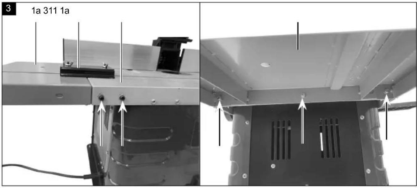
Step 2 (Fig. 6):
- Attach the pressure bar (2d) to the pressure bar holder (2e) using 2 carriage bolts M6 x 25 (d), 2 washers ∅ 6 (h) and 2 wing nuts M6 (i).
Step 3 (fig. 7):
- Insert the suction adapter (12) into the stop base body (2f).
Step 4 (fig. 8):
- Fix the vertical stop supports (2b) to the stop base body (2f) and to the movable stop (2c) using a hexagon socket screw M6 x 16 (g) each.
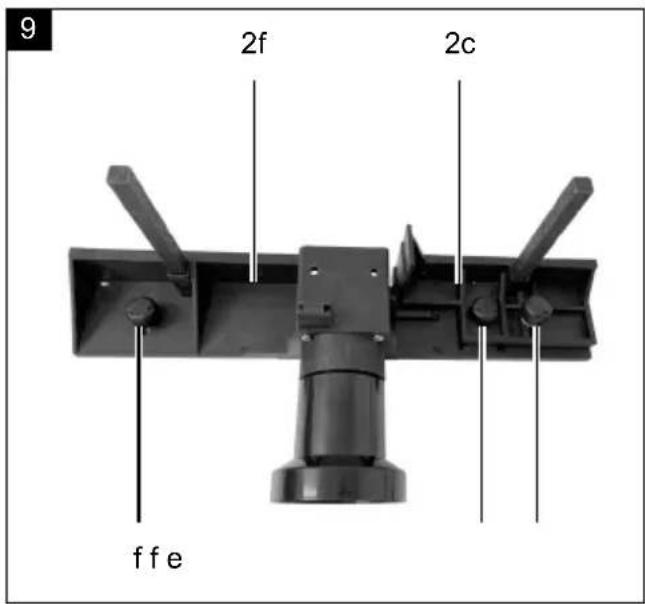
Step 5 (fig. 9):
- Place the movable stop (2c) in the groove provided in the stop base body (2f) and secure it using a carriage bolt M6 x 25 (d), washer ∅ 6 (h) and knurled nut M6 (b) and a carriage bolt M6 x 35 (e), washer ∅ 6 (h) and knurled nut M6 (b). - On the left side fit a carriage bolt M6 x 20 (f) with washer ∅ 6 (h) and counter-lock it with a knurled nut M6 (b).
Step 6 (Fig. 10 + 11)
- Insert two hexagonal bolts M6 x 40 (c) from below into the stop base body (2f) (Fig. 10).
- Fix the pressure bar holder (2e) to the pressure bar (2d) using the two M6 x 40 hexagon bolts (c), two ∅ 6 washers (h) and two M6 nuts (j). (fig. 11)
- To fasten the stop bars, fit four carriage bolts M6 x 20 (f), four washers ∅ 6 (h) and four knurled nuts M6 (b).
Step 7 (fig. 12):
- Attach the two support brackets horizontally (2h) with the retaining devices (2g) to the vertical stop supports (2b) using two fastening clamps (2i) and two knurled screws M6 (a) as shown in fig. 12.
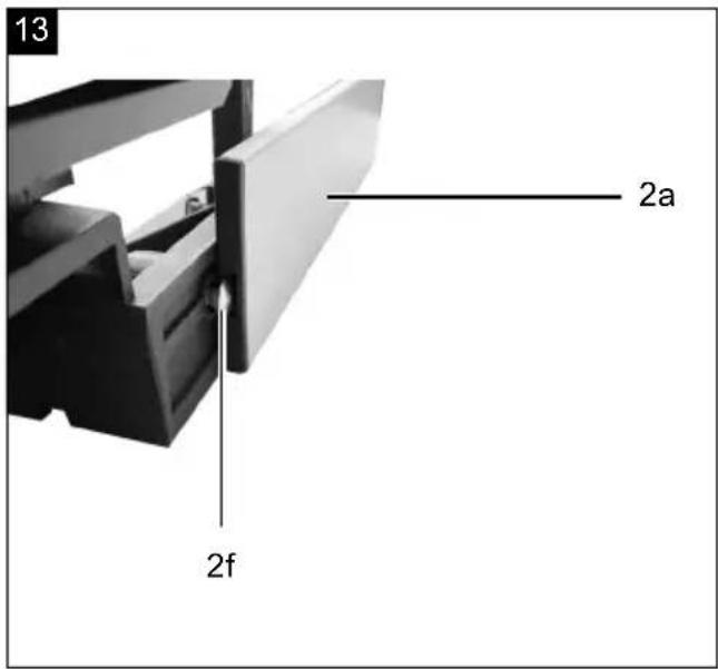
Step 8 (fig. 13+14):
- Slide the two stop bars (2a) with the carriage bolts M6 x 20 (2f) as shown in fig. 13 and 14.
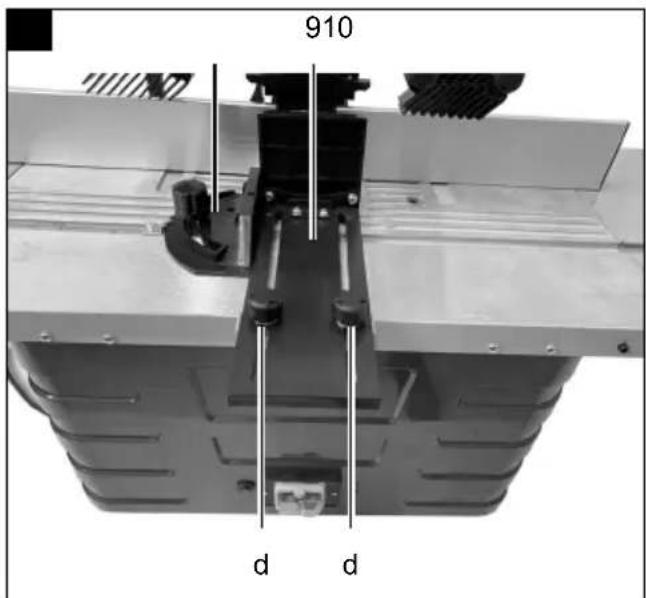
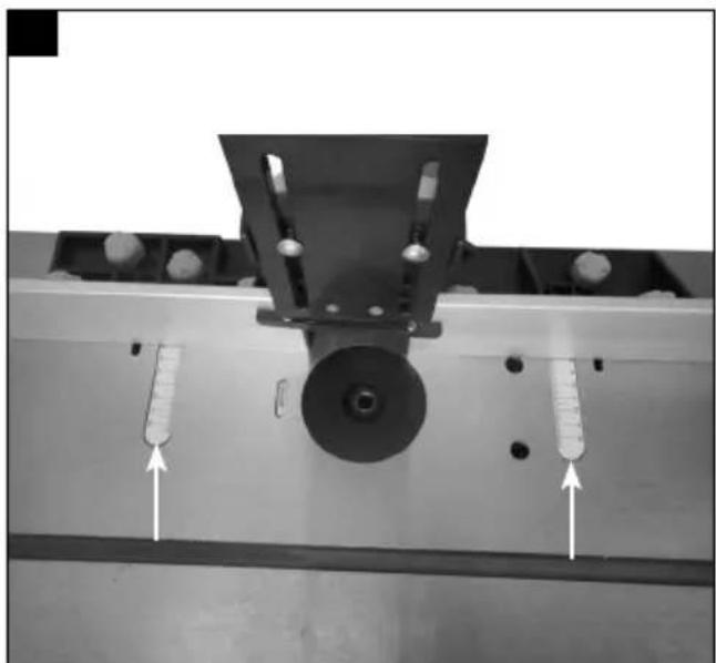
Step 9 (fig. 15+16):
- To mount the stop on the worktable (3), thread the two marked screws into the marked grooves on the worktable (3) and fasten them.
- Align the stop bars (2a) in the desired position and tighten the marked knurled nuts.
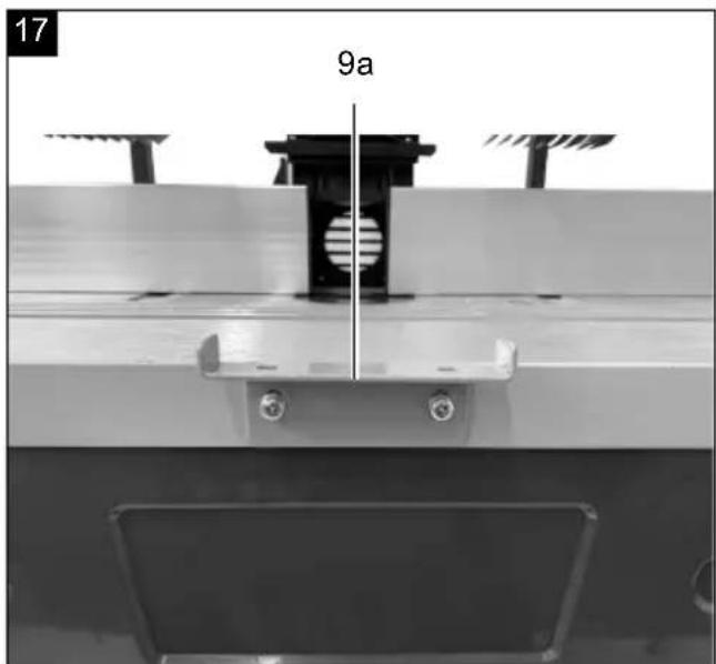
Installing the front pressure bar (Fig. 17 + 18)
- Fasten the front pressure bar holder with screws (9a) to the worktable using the screws provided (Fig. 17).
- Fix the pressure strip front (9) to the bracket (9a) using two carriage bolts M6 x 20 (f), two washers ∅ 6 (h) and two knurled nuts M6 (b) (fig. 18).
• The transverse stop (10) can be used for alignment.
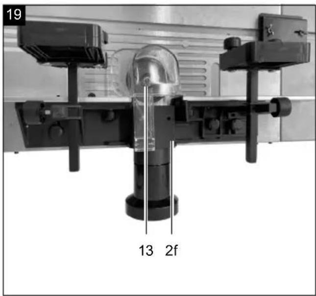
Installing the protective cover (Fig. 19)
- Fit the protective cover (13) to the stop base body (2f) and fix it in place using the aligning pin supplied.
NOTE: To fit the protective cover, the front pressure bar with bracket (9+9a) must be dismantled.
Connection of the milling machine to a suction system
- A connection to an external suction system for extracting dust and chips (not included in the scope of delivery) is provided.
- Push the vacuum hose of the suction system onto the suction adapter (12) at the back of the cutter stop (2). There is a conical adapter included in the packaging for hoses with a diameter of 100 mm.
10. Start up
⚠ Attention!
Always make sure the device is fully assembled before commissioning!
Attention: The milling machine has a shaft that is vertical to the work table. The axle is used to hold the cutting tools, discs and shaping cutters. The milling machine is used to produce friezes, single or multiple recesses, grooves, rebates, profiles and counter profiles on straight surfaces, etc.
Only cutters up to a maximum 50 mm in diameter may be used with the milling machine. If larger diameters are required, we recommend working in several steps and adjusting repeatedly using the handle (5), or adjusting the stop step by step.
Installing and changing the tool receiver
(Fig. 20 + 21)
⚠ Attention!
Pull out the mains plug of your machine before changing the tool receiver (15).
- Select the tool receiver that exactly matches the diameter of your cutter.
- Remove the reducer (14) from the opening (Fig. 20).
- Push the combination spanner SW 18 (16) directly under the locking nut of the tool receiver (14) and hold it in place.
- Use the combination screw SW24 (17) to loosen the locking nut of the tool receiver(14) anti-clockwise.
- Remove the tool receiver (14).
- Now insert the appropriate tool receiver and the appropriate milling tool. The milling tool must be inserted at least 20 mm.
- Tighten the locking nut of the tool receiver (14) with the Allen wrench SW24 (17).
- Place the reducer (14) for the opening to its original position.
- Adjust the stop as needed using the scale on the table.
- Attach the suction system. It is strongly recommended to connect a suction system to keep the opening free of chips, to cool the motor and to facilitate workpiece feeding.
• Re-connect the machine to the mains.
Setting the stop
The use of the stop is mandatory. Each task must be considered separately. Each time you use the machine, you must make sure that the protective devices are correctly installed and adjusted. Each time it is used again, each pressure piece must be readjusted on the stop.
Make sure that each screw is well tightened before you start cutting.
Use of the reducers
The reducers (14) must be used to reduce the distance between the table and the spindle to a minimum. Before switching on the machine, you must systematically check that the supplied reducers (14) are correctly installed.
Check that you have selected the appropriate reducer (14) for the cutting tool in question and its installation height in order to reduce the risk of the workpiece tilting when passing the hole.
The reducer (14) must surround the cutter as far as closely as possible.
Setting the tool speed, fig. 22 + 28
The speed setting (6) of the machine has 6 steps.
- Determine the optimum speed by making a test cut in a piece of waste material.
Attention: Using the correct speed will increase the service life of the cutter. It also influences the machined surface on the workpiece.
| Step Speed |
| 1 ca. 11,500 rpm |
| 2 ca. 13,000 rpm |
| 3 ca. 15,500 rpm |
| 4 ca. 18,000 rpm |
| 5 ca. 21,000 rpm |
| 6 ca. 24,000 rpm |
Note:
The values in the speed table (Fig. 28) are only guidelines. These can vary depending on the tool and type of wood.
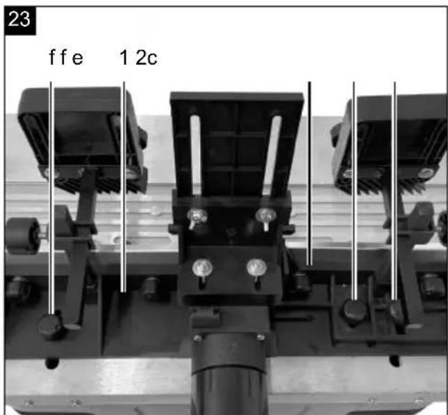
Setting the stop, Fig. 23 + 24
- The stop (1) must be adjusted to the size of the workpiece and the cutting tool.
- Loosen the two knurled nuts (f+e) on the back of the stop (1).
Set the stops and pressure devices such that they ensure the safe guidance of the workpiece at the input and output section of the machine.
- Slide the stop (1) to the desired position. Use the scale on the table (3) to determine the distance between the stop (1) and the centre of the cutter.
- Tighten the two knurled nuts on the back again to hold the stop (1) in this position.
Setting the stop for trimming, Fig. 23 + 24
- When trimming wood, the material that comes out of the cutter on the left is thinner than the material on the right.
- The movable stop (2c) must be adjusted to adapt to the thinner material. This serves to support the material and ensures a more accurate cut. To do this, loosen the right-hand knurled nut (f), move the movable stop (2c) forward and clamp it tight.
Setting the pressure bars, Fig. 25
The pressure bars (9+2d) may help you to hold the workpiece in place and prevent kick-back.
- Drive milling cutter to the lowest position
- Insert the workpiece to be machined and press the pressure bar (9+2d)A onto the workpiece with light pressure.
- Remove workpiece.
- Set the milling cutter to the desired height (see: Setting the working depth).
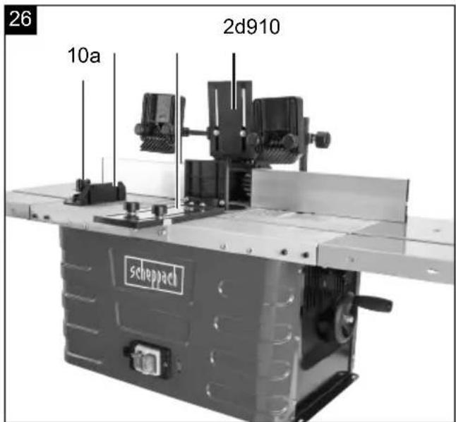
Setting the transverse cutting gauge, Fig. 26
- The transverse cutting gauge (10) slides horizontally along the worktable and is used to make edging and mitre cuts.
- To set the transverse cutting gauge (10) to the desired angle, loosen the transverse cutting gauge locking nut (10a) and turn it to the desired angle. Tighten the transverse cutting gauge locking nut (10a) again.
• Always make a test cut on a piece of waste material to ensure that the settings are correct.
Switching on and off, Fig. 22
Make sure that all keys and adjusting tools are removed from the router table, that the adjustments are complete and that all safety covers are fitted.
Press the on switch (7/“l”) to start the machine.
Press the off switch (7/0") to stop the machine.
Caution: The device starts running immediately at the set speed.
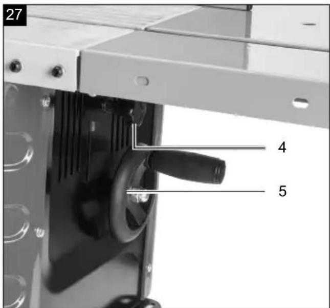
Setting the working depth (Fig. 27)
To adjust or decrease the spindle height (used to adjust the height of the cutter), turn the handle (5) to decrease or increase the height as desired.
Secure the setting by tightening the clamping screw (4).
11. Operation
- Insert an appropriate cutter in the tool receiver and secure this by tightening the tool receiver nut.
- Adjust speed, cutting depth, stop alignment and transverse cutting gauge.
- Make sure that you set the feed stop correctly so that it supports the uncut material. Adjust the out-feed stop to support the cut material while compensating for the removed material.
- Switch the cutter on.
• Make sure that the workpiece is pressed firmly against the stop.
- Push the workpiece gently from right to left against the direction of rotation of the tool.
- Keep the feed speed constant. Do not push too fast, this would slow down the motor too much.
- If you push too fast, you could get a poor quality cut. This could also damage the cutter or the motor.
- If you push too slowly, burn marks could appear on the workpiece.
- With very hard wood and large cuts, it may be necessary to do more than one working step to achieve the desired depth.
- The correct feed rate depends on the cutter size, the material type of the workpiece and the cutting depth. Practise with a piece of waste material first to find the right feed speed and dimensions.
- The machine is equipped with an overload switch to protect the motor. In the event of an overload, the machine stops automatically. After a while, the overload switch can be reset.
12. Electrical connection
The electrical motor installed is connected and ready for operation. The connection complies with the applicable VDE and DIN provisions.
The customer's mains connection as well as the extension cable used must also comply with these regulations.
Damaged electrical connection cable
The insulation on electrical connection cables is often damaged.
This may have the following causes:
- Pressure points, where connection cables are passed through windows or doors.
- Kinks where the connection cable has been improperly fastened or routed.
- Places where the connection cables have been cut due to being driven over.
• Insulation damage due to being ripped out of the wall outlet.
• Cracks due to the insulation ageing.
Such damaged electrical connection cables must not be used and are life-threatening due to the insulation damage.
Check the electrical connection cables for damage regularly. Ensure that the connection cables are disconnected from electrical power when checking for damage.
Electrical connection cables must comply with the applicable VDE and DIN provisions. Only use connection cables with the marking „H05VV-F“.
The printing of the type designation on the connection cable is mandatory.
For single-phase AC motors, we recommend a fuse rating of C 16A or K 16A for machines with a high starting current (from 3000 watts)!
13. Cleaning
Danger!
Disconnect the mains plug before carrying out any cleaning work.
- Keep protective devices, air vents and the motor housing as free of dust and dirt as possible. Rub the device clean with a clean cloth or blow it off with compressed air at low pressure.
• We recommend that you clean the device directly after every use. - Clean the device at regular intervals using a damp cloth and a little soft soap. Do not use any cleaning products or solvents; they could attack the plastic parts of the device. Make sure that no water can penetrate the device interior. Water penetrating an electric device increases the risk of an electric shock.
14. Storage
Store the device and its accessories in a dark, dry and frost-free place that is inaccessible to children. The optimum storage temperature lies between 5 and 30 °C. Store the tool in its original packaging. Cover the tool to protect it from dust or moisture. Store the operating manual with the tool.
15. Maintenance
The device has no further internal parts that require maintenance.
- Before each start-up, make sure that the safety devices are in perfect condition and are working properly.
- Check all connections and tighten them if necessary before each new start-up.
Service information
With this product, it is necessary to note that the following parts are subject to natural or usage-related wear, or that the following parts are required as consumables.
Wearing parts*:Carbon brushes, cutter
* may not be included in the scope of supply!
Connections and repairs
Connections and repair work on the electrical equipment may only be carried out by electricians.
Please provide the following information in the event of any queries:
• Type of current for the motor
• Machine data - type plate
• Engine data - type plate
Spare parts and accessories can be obtained from our Service Centre. To do this, scan the QR code on the front page.
16. Disposal and recycling
Notes for packaging


The packaging materials are recyclable. Please dispose of packaging in an environmentally friendly manner.
Notes on the electrical and electronic equipment act [ElektroG]

Waste electrical and electronic equipment does not belong in household waste, but must be collected and disposed of separately!
- Used batteries or rechargeable batteries that are not installed permanently in the old appliance must be removed non-destructively before disposal. Their disposal is regulated by the battery law.
- Owners or users of electrical and electronic devices are legally obliged to return them after use.
- The end user is responsible for deleting their personal data from the old device being disposed of!
- The symbol of the crossed-out dustbin means that waste electrical and electronic equipment must not be disposed of with household waste.
- Waste electrical and electronic equipment can be handed in free of charge at the following places:
- Public disposal or collection points (e.g. municipal works yards)
- Points of sale of electrical appliances (stationary and online), provided that dealers are obliged to take them back or offer to do so voluntarily.
- Up to three waste electrical devices per type of device, with an edge length of no more than 25 centimetres, can be returned free of charge to the manufacturer without prior purchase of a new device from the manufacturer or taken to another authorised collection point in your vicinity.
- Further supplementary take-back conditions of the manufacturers and distributors can be obtained from the respective customer service.
- If the manufacturer delivers a new electrical appliance to a private household, the manufacturer can arrange for the free collection of the old electrical appliance upon request from the end user. Please contact the manufacturer's customer service for this.
- These statements only apply to devices installed and sold in the countries of the European Union and which are subject to the European Directive 2012/19/EU. In countries outside the European Union, different regulations may apply to the disposal of waste electrical and electronic equipment.
17. Troubleshooting
The following table shows fault symptoms and describes remedial measures in the event of your machine failing to work properly. If you cannot localise and rectify the problem with this, please contact your service workshop.
| Fault Possible cause Remedy | ||
| The machine will not switch on | Mains voltage is not available. | Check power supply |
| Carbon brushes worn Contact the customer service workshop | ||
| Machine switches off automatically while idling | Mains failure | Check fuse on the mains side. |
| Due to the built-in undervoltage protection, the machine does not restart by itself and must be switched on again when the voltage is restored. | ||
| Machine stops during machining | Overload protection has tripped due to the cutter blade being blunt, or the feed rate or cutting depth being too great | Before continuing work, replace the blades or wait for the motor to cool down. |
| Speed drops during machining | High degree of chip take-off Reduce chip take-off | |
| Feed to high Reduce the feed speed | ||
| Blunt cutter Replace cutter | ||
| Untidy cutting pattern | Blunt cutter Replace cutter | |
| Uneven feed Cut with constant pressure and reduced feed rate | ||
| Chip ejector clogged (without extraction) | High degree of chip take-off Reduce chip take-off | |
| Blunt cutter Replace cutter | ||
| Wood is too wet Only machine dry wood. | ||
Günzburger Straße 69
D-89335 Ichenhausen
Cher client,
Günzburger Straße 69
89335 Ichenhausen, Germania
Egregio cliente,
Günzburger Straße 69
D-89335 Ichenhausen
Geachte klant,
Günzburger Straße 69
Günzburger Straße 69
Günzburger Straße 69
D-89335 Ichenhausen
Vážený zákazníku,
Günzburger Straße 69
D-89335 Ichenhausen
Vážený zákazník,
Günzburger Straße 69
D-89335 Ichenhausen
Kedves Ügyfelünk!
Günzburger Straße 69
D-89335 Ichenhausen
Szanowny Kliencie,
Günzburger Straße 69
D-89335 Ichenhausen
Poštovani kupci,
Günzburger Straße 69
D-89335 Ichenhausen
Spoštovani kupec,
želimo vam veliko veselja in uspeha pri delu z vašo novo napravo.
Napotek:
Negotovost K_wa/pA 3 dB
8. Razpakiranje
| 1 pribl. 11500 min | -1 |
| 2 pribl. 13000 min | -1 |
| 3 pribl. 15500 min | -1 |
| 4 pribl. 18000 min | -1 |
| 5 pribl. 21000 min | -1 |
| 6 pribl. 24000 min | -1 |
Napotek:
Günzburger Straße 69
D-89335 Ichenhausen
Austatud klient!
Günzburger Straße 69
D-89335 Ichenhausen
Gerbiamas kliente,
Günzburger Straße 69
Günzburger Straße 69
D-89335 Ichenhausen
Bästa Kund!
Günzburger Straße 69
D-89335 Ichenhausen
Arvoisa asiakas
Günzburger Straße 69
D-89335 Ichenhausen
Kære kunde,
Günzburger Straße 69
D-89335 Ichenhausen
Kjære kunde
Günzburger Straße 69
D-89335 Ichenhausen, Германия
Уважаеми клиенти,
Günzburger Straße 69
D-89335 Ichenhausen
Αξιότιμε πελάτη
Günzburger Straße 69
D-89335 Ichenhausen
Stimate client
Günzburger Straße 69
D-89335 Ichenhausen
Poštovani kupče
Günzburger Straße 69
D-89335 Ichenhausen
İthalatçı:
EU Declaration of Conformity
Standard references:
EN 61029-1:2009+A11:2010; EN 61029-2-8:2010;
EN IEC 55014-1:2021; EN IEC 61000-3-2:2019+A1:2021; EN 61000-3-3:2013+A1:2019; EN IEC 55014-2:2021
This declaration of conformity is issued under the sole responsibility of the manufacturer.
The object of the declaration described above fulfils the regulations of the directive 2011/65/EU of the European Parliament and Council from 8th June 2011, on the restriction of the use of certain hazardous substances in electrical and electronic equipment.
Subject to change without notice
Documents registrar: Dawid Hudzik
Günzburger Str. 69, D-89335 Ichenhausen
EU Declaration of Conformity
| 2006/42/EG | |
| X | Annex IV Notified Body: SGS Fimko Ltd Notified Body No.: 0598 Certificate No.: MD-430 Issue 2 |
Standard references:
EN 61029-1:2009+A11:2010; EN 61029-2-8:2010;
EN IEC 55014-1:2021; EN IEC 61000-3-2:2019+A1:2021; EN 61000-3-3:2013+A1:2019; EN IEC 55014-2:2021
This declaration of conformity is issued under the sole responsibility of the manufacturer.
The object of the declaration described above fulfils the regulations of the directive 2011/65/EU of the European Parliament and Council from 8th June 2011, on the restriction of the use of certain hazardous substances in electrical and electronic equipment.
Subject to change without notice
Documents registrar: Dawid Hudzik
Günzburger Str. 69, D-89335 Ichenhausen
EU Declaration of Conformity
AB uygunluk beyanı
CE
Scheppach GmbH, Günzburger Str. 69, D-89335 Ichenhausen
| DE | erklärt folgende Konformität gemäß EU-Richtlinien und Normen für den Artikel | RO | declară următoarea conformitate corespunzător directivelor și normelor UE pentru articolul |
| GB | hereby declares the following conformity under the EU Directive and standards for the following article | GR | δηλώνει την ακόλουθη συμμόρφωση σύμφωνα με την Οδηγία ΕΕ και τα πρότυπα για το προϊόν |
| BG | декларира съответното съответствие съгласно Дирек-тива на ЕС и норми за артикул | TR | Burada açıklanan ürünün geçerli yönetmeliklere ve standartlara uygun olduğunu tamamen kendi sorumluluğumuz altında beyan ediyoruz. |
| RS | potvrđuje sledeću usklađenost prema smernicama EZ i normemu ta artikel |
Article name: TABLE ROUTER - HF60
Ürün Tanım: TEZGAHLI FREZE MAKINESI - HF60
| 2000/14/EG_2005/88/EG | ||
| Noise: measured L_WA = xx dB; guaranteed L_WA = xx dB | ||
| Annex V | ||
| Annex VI | ||
| X 2006/42/EG | |
| X | Annex IVNotified Body: SGSNotified Body No.: 1Certificate No.: MD |
| mko Ltd80 Issue 2 |
| 2016/1628/EU | |
| Emission. No: |
Standard references:
EN 61029-1:2009+A11:2010; EN 61029-2-8:2010;
EN IEC 55014-1:2021; EN IEC 61000-3-2:2019+A1:2021; EN 61000-3-3:2013+A1:2019; EN IEC 55014-2:2021
This declaration of conformity is issued under the sole responsibility of the manufacturer.
The object of the declaration described above fulfils the regulations of the directive 2011/65/EU of the European Parliament and Council from 8th June 2011, on the restriction of the use of certain hazardous substances in electrical and electronic equipment.
Subject to change without notice
Documents registrar: Dawid Hudzik
Günzburger Str. 69, D-89335 Ichenhausen
Garantie DE
Apparent defects must be notified within 8 days from the receipt of the goods. Otherwise, the buyer loses its rights of claim due to such defects are invalidated. We guarantee for our machines in case of proper treatment for the time of the statutory warranty period from delivery in such a way that we replace any machine part free of charge which provably becomes unusable due to faulty material or defects of fabrication within such period of time. With respect to parts not manufactured by us we only warrant insofar as we are entitled to warranty claims against the upstream suppliers. The costs for the installation of the new parts shall be borne by the buyer. The cancellation of sale or the reduction of purchase price as well as any other claims for damages shall be excluded.
Garantie FR
Apparent defects must be notified within 8 days from the receipt of the goods. Otherwise, the buyer's rights of claim due to such defects are invalidated. We guarantee for our machines in case of proper treatment for the time of the statutory warranty period from delivery in such a way that we replace any machine part free of charge which provably becomes unusable due to faulty material or defects of fabrication within such period of time. With respect to parts not manufactured by us we only warrant insofar as we are entitled to warranty claims against the upstream suppliers. The costs for the installation of the new parts shall be borne by the buyer. The cancellation of sale or the reduction of purchase price as well as any other claims for damages shall be excluded.
Záruka CZ
Apparent defects must be notified within 8 days from the receipt of the goods. Otherwise, the buyer is rights of claim due to such defects are invalidated. We guarantee for our machines in case of proper treatment for the time of the statutory warranty period from delivery in such a way that we replace any machine part free of charge which provably becomes unusable due to faulty material or defects of fabrication within such period of time. With respect to parts not manufactured by us we only warrant insofar as we are entitled to warranty claims against the upstream suppliers. The costs for the installation of the new parts shall be borne by the buyer. The cancellation of sale or the reduction of purchase price as well as any other claims for damages shall be excluded.
Garantii EE
Apparent defects must be notified within 8 days from the receipt of the goods. Otherwise, the buyer's rights of claim due to such defects are invalidated. We guarantee for our machines in case of proper treatment for the time of the statutory warranty period from delivery in such a way that we replace any machine part free of charge which provably becomes unusable due to faulty material or defects of fabrication within such period of time. With respect to parts not manufactured by us we only warrant insofar as we are entitled to warranty claims against the upstream suppliers. The costs for the installation of the new parts shall be borne by the buyer. The cancellation of sale or the reduction of purchase price as well as any other claims for damages shall be excluded.
гаранция BG

- HF60
- Verehrter Kunde
- Explanation of the symbols on the device
- Table of contents: Page:
- Introduction
- Manufacturer:
- Dear Customer
- Note:
- Device description (Fig. 1)
- Scope of delivery
- Proper use
- General safety instructions
- Safe work
- ATTENTION!
- The operator must always stand in front of the machine to avoid danger.
- ADDITIONAL SAFETY INSTRUCTIONS
- Residual risks
- Technical data
- Noise and vibration
- Noise data
- Unpacking
- ⚠ WARNING!
- Layout
- Attention:
- Fastening the machine
- Parts for table width extension (Fig. 2)
- Installing the table width extensions (Fig. 3)
- Parts for cutter stop (Fig. 4)
- Installing the cutter stop (Fig. 5 - 16)
- Step 1 (Fig. 5)
- Step 2 (Fig. 6):
- Step 3 (fig. 7):
- Step 4 (fig. 8):
- Step 5 (fig. 9):
- Step 6 (Fig. 10 + 11)
- Step 7 (fig. 12):
- Step 8 (fig. 13+14):
- Step 9 (fig. 15+16):
- Installing the front pressure bar (Fig. 17 + 18)
- Installing the protective cover (Fig. 19)
- Connection of the milling machine to a suction system
- Start up
- ⚠ Attention!
- Always make sure the device is fully assembled before commissioning!
- Installing and changing the tool receiver
- (Fig. 20 + 21)
- Setting the stop
- Use of the reducers
- Setting the tool speed, fig. 22 + 28
- Setting the stop, Fig. 23 + 24
- Set the stops and pressure devices such that they ensure the safe guidance of the workpiece at the input and output section of the machine.
- Setting the stop for trimming, Fig. 23 + 24
- Setting the pressure bars, Fig. 25
- Setting the transverse cutting gauge, Fig. 26
- Switching on and off, Fig. 22
- Setting the working depth (Fig. 27)
- Operation
- Electrical connection
- Damaged electrical connection cable
- Cleaning
- Danger!
- Storage
- Maintenance
- Service information
- Connections and repairs
- Disposal and recycling
- Notes for packaging
- Troubleshooting
- Cher client,
- Egregio cliente,
- Geachte klant,
- Vážený zákazníku,
- Vážený zákazník,
- Kedves Ügyfelünk!
- Szanowny Kliencie,
- Poštovani kupci,
- Spoštovani kupec,
- Napotek:
- Razpakiranje
- Austatud klient!
- Gerbiamas kliente,
- Bästa Kund!
- Arvoisa asiakas
- Kære kunde,
- Kjære kunde
- Уважаеми клиенти,
- Αξιότιμε πελάτη
- Stimate client
- Poštovani kupče
- İthalatçı:
- EU Declaration of Conformity
- Standard references:
- AB uygunluk beyanı
- Garantie DE
- Garantie FR
- Záruka CZ
- Garantii EE
- гаранция BG
Brand : SCHEPPACH
Model : Tiger 7000s
Category : Grinder