Slik 7.0b - Grinder SCHEPPACH - Free user manual and instructions
Find the device manual for free Slik 7.0b SCHEPPACH in PDF.

| Product Type | Edge sander (grinder) |
| Brand | Scheppach |
| Model | Slik 7.0b |
| Dimensions (L x W x H) | 1540 x 700 x 1215 mm |
| Weight | 135 kg |
| Power supply | 230–240 V / 50 Hz (single-phase), 400 V / 50 Hz (three-phase) |
| Input power (P1) | 2.90 kW |
| Output power (P2) | 2.20 kW |
| Rotation speed | 2800 rpm |
| Abrasive belt speed | 16 m/s |
| Abrasive belt dimensions | 2000 x 150 mm |
| Abrasive belt grit | 80 |
| Longitudinal table (L x W) | 900 x 305 mm |
| Transverse table (L x W) | 290 x 225 mm |
| Table height | 904 – 1020 mm |
| Sanding angle adjustment | 0° – 90° |
| Suction hose diameter | 100 mm |
| Main functions | Edge sanding, arc sanding, angle sanding, cross-cutting with template |
| Maintenance and cleaning | Clean after each use; oil moving parts regularly; apply a thin layer of wax on the work table |
| Safety | Use protective equipment (goggles, dust mask); do not wear loose clothing; disconnect before any intervention; follow general safety instructions |
| Spare parts and repairability | Use only original Scheppach spare parts; contact authorized after-sales service for electrical repairs |
| General information | Machine delivered assembled; recommended fixing on a post; complies with EC machinery directive; sound pressure level: 77 dB(A) at idle, 87 dB(A) during machining |
Frequently Asked Questions - Slik 7.0b SCHEPPACH
User questions about Slik 7.0b SCHEPPACH
0 question about this device. Answer the ones you know or ask your own.
Ask a new question about this device
Download the instructions for your Grinder in PDF format for free! Find your manual Slik 7.0b - SCHEPPACH and take your electronic device back in hand. On this page are published all the documents necessary for the use of your device. Slik 7.0b by SCHEPPACH.
USER MANUAL Slik 7.0b SCHEPPACH
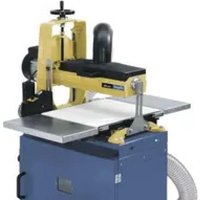
natural_image
Industrial machine with handle and control panel (no visible text or symbols)| D | Antenschleifmaschine 03-07 | |
| GB | Edge grinding machine 08-11 | |
| FR | Conceuse de chants 12-16 | |
| NL | Lantschuurmachine 17-21 | |
| FIN | Reunahlomakone 22-25 | |
| I | Levigatrice oscillante per bordi | 26-29 |
| DK | Kantslipemaskine 30-33 | |
| SE | Kantslipemaskin | 34-37 |
| NO | Kantslipemaskin | 38-41 |
| I | Levigatrice oscillante per bordi |
| OK | Kantslibemaskine |
| SE | Kantslipmaskin |
| NO | Kantslipemaskin |
| D | Kantenschleifmaschine |
| GB | Edge grinding machine |
| FR | Ponceuse de chants |
| NL | Kantschuurmachine |
| FIN | Reunahlomakone |
natural_image
Four-panel mechanical assembly diagram showing progressive assembly steps with labeled components (no readable text or symbols)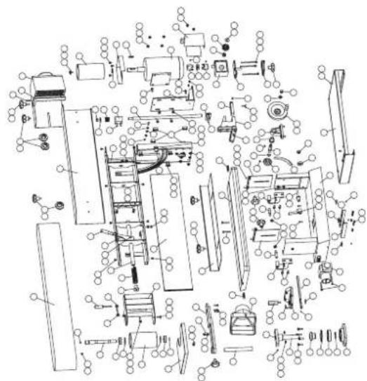
natural_image
Exploded view diagram of a mechanical assembly (no text or labels visible)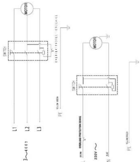
natural_image
Three-panel technical diagram showing mechanical components with labeled parts (no readable text or symbols)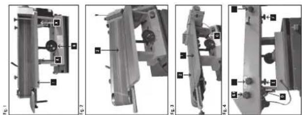
natural_image
Four-panel mechanical assembly diagram showing exploded views of a device with labeled components (no readable text or symbols)Hersteller:
Scheppach
Günzburger Straße 69
D-89335 Ichenhausen
Verehrter Kunde,
Günzburger Straße 69
D-89335 Ichenhausen
Dear customer,
we wish you a pleasant and successful working experience with your new machine.
Note:
According to the applicable product liability law the manufacturer of this device is not liable for damages which arise on or in connection with this device in case of:
parts
pliance with the electrical specifications and the VDE 0100, DIN 57113 / VDE 0113 regulations
Recommendations:
Read the entire text of the operating instructions prior to the assembly and operation of the device.
These operating instructions are intended to make it easier for you to get familiar with your device and utilize its intended possibilities of use.
The operating instructions contain important notes how to work safely, properly and economically with your machine and how to avoid dangers, save repair costs, reduce downtime, and increase the reliability and working life of the machine.
In addition to the safety regulations contained herein, you must in any case comply with the applicable regulations of your country with respect to the operation of the machine.
Put the operating instructions in a clear plastic folder to protect them from dirt and humidity, and store them near the machine. The instructions must be read and carefully observed by each operator prior to starting the work. Only persons who have been trained in the use of the machine and have been informed on the related dangers and risks are allowed to use the machine. The required minimum age must be met.
General Notes
sible transport damages. In case of complaints the supplier is to be informed immediately. Complaints received at a later date will not be acknowledged.
iar with the device prior to using it.
wearing and spare parts. Spare parts are available from your specialized scheppach dealer.
of construction of the device in your orders.
Slik 7.0b
| Scope of delivery | |
| Edge grinding machine | |
| Work piece stop | |
| Grinding belt cover front | |
| Grinding belt cover rear | |
| Suction connector | |
| Grinding belt, linen K80/K120/K240 | |
| Assembly tools | |
| Grinding rollers D 40/53/78 | |
| Cross table inserts 43/56/81 | |
| Base | |
| Adapter plate | |
| Extraction hood | |
| Longitudinal stop 550 x 175 mm | |
| Chisel edge template 30° - 90° - 30° | |
| Specifications | |
| DimensionsL x W x H mm | 1540/700/1215 |
| Longitudinal tableL x W mm | 900/305 |
| Cross tableL x W mm | 290/225 |
| Table height mm | 904 – 1020 |
| Adjustment grinding rest | 0 – 90 |
| Grinding belt length/ width mm | 2000/150 |
| Grinding rest mm | 900 |
| Grinding belt granulation | 80 |
| Belt speed m/sec | 16 |
| ø Suction connector mm | 100 |
| Weight kg | 135,0 |
| Drive | |
| Motor V/Hz | 230–240/50 400 / 50 |
| Input P1 kW | 2,90 |
| Output P2 kW | 2,20 |
| Operating mode | S6 / 40% |
| Rotational speed | 2800 |
| Undervoltage release | yes |
| Plug | Schuko CEE |
Subject to technical modifications!
Noise parameters according to EN 23746
The noise emission values determined according to EN 23746 for the sound power level or according to EN 31202 (correction factor k3 calculated according to Annex A.2 of EN 31204) for the sound level at the work place are based on the working conditions specified in ISO 7960 Annex A and are as follows:
Sound power level at the work place in dB
Idle running L_WA = 77.0 dB(A)
Processing L_WA = 87.0 dB(A)
Sound level at the work place in dB
Idle running L_pAeq = 69.0 dB(A)
Processing L_pAeq = 77.0 dB(A)
A measuring uncertainty allowance K=4 dB applies for the specified emission values.
Specifications regarding the dust emission
The dust emission values that were measured according to the “Principles for the evaluation of the dust emission (concentration parameters) of wood working machines” of the Fachausschuss Holz (Expert committee wood) are be-
low 2 mg/m ^3 . Thus, it can be assumed that the TRK limit value for wood dust applicable in the Federal Republic of Germany is permanently and reliably fallen short of when the machine is connected to a proper operational suction plant with an air speed of at least 20 m/s. Please observe the load values of the material manufacturer depending on the materials to be processed or the material quality.
In these operating instructions we have marked the places that have to do with your safety with this sign: △
General Safety Rules
When using electric tools basic safety precautions should always be followed to reduce the risk of fire, electric shock and personal injury.
of checking to see that keys and adjusting wrenches are removed from the machine before turning it on.
benches invite accidents.
tools in damp or wet locations, or expose them to rain. Keep work area well lighted.
distance from the work area.
Tools not used should be kept in a dry place, inaccessible for children.
at the rate for which it was designed.
to do a job for which is was not designed.
cord is in good condition. When using an extension cord, be sure to use one heavy enough to carry the current your product will draw. An undersized cord will cause a drop in voltage resulting in loss of power and overheating.
neckties, rings, bracelets, or other jewelry which may get caught in moving parts. Nonslip shoes are recommended. Wear protective hair covering to contain long hair. Roll your sleeves up to above the elbows.
offer only little protection. They are no safety glasses. Wear a face or dust mask when working in a dusty environment.
practical. It is safer than using your hand, and it frees both hands to operate the tool.
all times.
for best and safest performance. Follow the instructions for lubricating, and changing accessories.
when changing accessories, such as blades, bits, cutters, and the like.
ating instructions for the recommended accessories. The use of improper accessories may cause risk of injury to persons.
if the machine is tipped or if the cutting tool is unin-
tentionally contacted.
a guard or other part that is damaged should be carefully checked to determine that it will operate properly and perform its intended function. Check for alignment or binding of moving parts, breakage of parts, mounting, and any other conditions that may affect its operation. A guard or other part that is damaged should be properly repaired or replaced.
sawblade or cutter only in the moving direction of the tool.
Wait until the tool has come to an absolute standstill, before you leave the machine.
plug to stop the machine during work. Never remove the plug from the socket by pulling the extension cord.
using the machine regularly. Bear in mind that a fraction of a second is sufficient to cause an injury.
common sense and staying alert as long as the machine is switched on.
Additional safety rules for the edge grinding machine
pletely assembled and installed according to the instructions.
machine, ask the head of the department, your teacher, or any other qualified person.
sanding wood or similar materials. The sanding of other materials can cause fire, injuries, or damage the product.
zontal surface. A non-horizontal surface can damage the motor.
sanding long and heavy panels), it must be fastened to a solid surface of sufficient carrying force.
tion – see arrows at the back of the belt.
it cannot come off the drive pulleys.
in horizontal position.
ing the sanding disc.
ing disc running downwards, in order to maintain the workpiece pressed to the table. By using the upward-running side of the sanding disc, the workpiece could be ejected and cause injury to persons.
less between the table or fence and the sanding belt or disc.
cloth during sanding.
ing with the wood.
could cause your hand to touch the sanding belt or disc.
ditional support at table height.
workpiece with the table or the fence. Exceptions are the sanding of curved workpieces on the outside of the sanding disc.
or other objects, before turning the machine on.
the table while the sanding machine is in operation.
the socket when fitting or removing accessories.
while the tool is running, or as long as it has not come to an absolute standstill.
Proper Use
The machine meets the currently valid EU machine directive.
the dimensions set forth in the specifications must be observed.
dents and other, generally recognized safety rules must be observed.
by trained persons who are familiar with the machine and have been informed about the dangers. Unauthorized modifications of the machine exclude a liability of the manufacturer for damages resulting from the modifications.
and original tools of the manufacturer.
manufacturer excludes any liability for resulting damages, the risk is exclusively borne by the user.
Residual Risks
The machine has been constructed according to the state of the art and the recognized safety rules. Nevertheless, single residual risks may occur during the operation.
tating grinding roller in the case of an improper guidance or support of the work piece to be ground.
an improper support or guidance.
trical connecting lines are used.
spite of all measures taken.
the Safety Notes and the Intended Use as well as the entire operating instructions.
Assembly
The machine is completely pre-assembled. We recommend attaching the machine to a base or the like. 4 screws are enclosed for the attachment to the Schep- pach base (accessory).
⚠️ Initial Operation
Vertical grinding Fig. 1
Height adjustment of the table
left sides under the table. (1)
height is reached.
Angle grinding Fig. 2
the table
tion (0°- 90°)
Horizontal grinding Fig. 3
the table
position (0°)
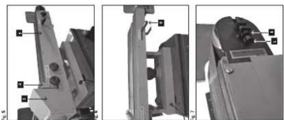
Changing the grinding belt Fig. 4, 5, 6
Un-tighten the three fastening knobs (D, E & F) located under the table. Following that, remove the handles (G, H & I) on the side, Fig. 4
Now you can remove the extraction protection (3), the grinding stop plate (4) and the grinding protection (5), Fig. 5.
By means of the lever (6), the grinding belt can be un-tightened. Fig.6
Afterwards, remove the grinding belt and replace it by a new one.
Following that, move back the lever (6) to tension the grinding belt.
Note: When inserting the grinding belt, observe the arrows that are printed on the inside of the belt. They indicate the correct rotating direction.
Mount all protective equipment again in reversed order, as described above, before you put the machine into operation again.
Adjustment of the grinding belt. Fig. 7
Note: The grinding belt should move within the sliding layer during operation.
Adjustments can be made as follows.
1 Unfasten the counter nut (K).
2 If you rotate the adjusting screw (L) clockwise, the belt is moved inwards. Rotation in contrary direction moves it outwards.
3 Following that, refasten the counter nut (K).
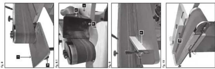
Curve grinding Fig. 8
For curve grinding, the supporting table (7) is inserted into the bracket and fastened by the clamping bolt (M). In order to wear the belt evenly, the table is infinitely adjustable.
For curve grinding, the additional extraction hood (A) is fastened to the grinding table (C) by a slot nut and a rotary handle (B) (see Fig. 8.1).
Lateral cutting gauge Fig. 9
For frontal grinding, a lateral cutting gauge (8) may be applied. The gauge is adjustable in both directions from 90^-30^ .
To control long work pieces, a longitudinal stopper (9) can be used.
Electrical Connection
The installed electric motor is connected and is ready to work.
The connection complies with the relevant VDE and DIN regulations.
The customer-side network connection and the used extension line must comply with these provisions.
Installations, repair, and maintenance work relating to the electric installation may only be performed by specialists.
Important notes
The electric motor is designed for operating mode S 1. If the motor is overload it is turned off automatically. After a (varying) cooling period the motor can be turned on again.
⚠ Maintenance
Slightly lubricate the work table before working. This facilitates the final cleaning of the work table.
Warning: Exclusively use original spare parts for the maintenance/service.
Disconnect the mains plug prior to each intervention in the grinding machine.
General maintenance notes
The grinding machine must be cleaned carefully after each deployment. Regularly lubricate all moveable parts. Treat the work table with a thin layer of automotive type paste wax. This facilitates the cleaning of the work table.
Trouble shooting
| Problem Possible Cause Help | ||
| Motor does not start | a) ON/OFF switch damaged.b) ON/OFF cable damaged.c) ON/OFF relay damaged.d) Fuse burnt-out.e) Motor burnt-out. | a-d) Replace all damaged parts before you use the grinding machine.e) Contact your local service centre or an authorized service station. Each attempted repair may cause dangers if not performed by a qualified expert. |
| Machine gets slower during the work | An excessive pressure is exerted on the work piece. | Exert less pressure on the work piece. |
| Grinding belt runs off the drive wheels. | It does not run in the track. | Readjust the track. |
| Wood burns during the grinding operation. | a) Sanding disc or belt covered with grease.b) An excessive pressure is exerted on the work piece. | a) Replace the belt or the disk.b) Reduce the pressure on the work piece. |
Constructeur:
scheppach, Günzburger Straße 69, D-89335 Ichenhausen
Cher client,
Günzburger Straße 69
D-89335 Ichenhausen
Gentile cliente,
Günzburger Straße 69
D-89335 Ichenhausen
Krere kunde,
Günzburger Straße 69
D-89335 Ichenhausen
Arade kund!
Günzburger Straße 69
D-89335 Ichenhausen
Kjrere kunde,
Støy under arbeide--dB(A) 89,0 89,0
Støynormer
rg 4000 benyttes for avsuging.
Tuotannossa LWA = 87,0 dB(A)
Tuotannossa LpAeq = 77,0 dB(A)
| X | 2006/42/EC |
| X | 2006/95/EC |
| X | 2004/108/EC |
| 2000/14/EC Annex V Noise: =measured LWA = dB(A);=guaranteed LWA = dB(A)P = kW | |
| 2005/88/EC |
EN 12100-1; EN 12100-2; EN 13857; EN 60204-1; EN 61029-1; EN 61029-2-5;
The technical documentation is kept by
CE