Tiger 3000VS - Grinder SCHEPPACH - Free user manual and instructions
Find the device manual for free Tiger 3000VS SCHEPPACH in PDF.

| Product Type | Water-cooled sharpening grinder |
| Brand | Scheppach |
| Model | Tiger 3000VS |
| Dimensions (L x W x H) | 380 x 290 x 90 mm |
| Weight | 11 kg |
| Power supply | 230-240 V~ / 50 Hz |
| Power consumption (P1) | 180 W |
| Motor rotation speed | 1950 - 3250 rpm |
| Grinding wheel rotation speed (adjustable) | 90 - 150 rpm |
| Grinding wheel diameter | 250 x 12 x 63 mm |
| Cutting speed | 1.2 - 2 m/s |
| Operating mode | S1 (continuous operation) |
| Sound pressure level (L_pA) | 94 dB(A) |
| Sound power level (L_WA) | 107 dB(A) |
| Protection class | II |
| Main functions | Water sharpening, leather disc grinding, continuous speed adjustment |
| Safety | Wear hearing protection, safety glasses, dust mask; protection class II |
| Maintenance and cleaning | Clean after each use; store in a dry, frost-free place |
| Wear parts | Carbon brush, abrasive, deburring discs, angle guides, V-belts |
| Included accessories | Sharpening stone, workpiece holder, universal support, angle gauge, water tank, leather abrasive disc |
Frequently Asked Questions - Tiger 3000VS SCHEPPACH
User questions about Tiger 3000VS SCHEPPACH
0 question about this device. Answer the ones you know or ask your own.
Ask a new question about this device
Download the instructions for your Grinder in PDF format for free! Find your manual Tiger 3000VS - SCHEPPACH and take your electronic device back in hand. On this page are published all the documents necessary for the use of your device. Tiger 3000VS by SCHEPPACH.
USER MANUAL Tiger 3000VS SCHEPPACH
natural_image
Industrial milling machine labeled 'Scheppach' and 'VARIO SPEED', no visible text beyond labels
TIGER 3000VS
| DE | Nass-SchleifsystemOriginalbedienungsanleitung | 6 |
| GB | Wet grinding systemTranslation of original instruction manual | 21 |
| FR | Système d'affûtage à eauTraduction des instructions d'origine | 34 |
| IT | Sistema di molatura a umidoLa traduzione dal manuale di istruzioni originale | 47 |
| NL | Nat-slijpsysteemVertaling van de originele gebruikshandleiding | 61 |
| ES | Sistema de rectificado en húmedoTraducción del manual de instrucciones original | 74 |
| PT | Sistema de retificação a húmidoTradução do manual de operação original | 88 |
| CZ | Systém broušení za mokraPřeklad originálního návodu k obsluze | 101 |
| SK | Systém mokrého brúseniaPreklad originálneho návodu na obsluhu | 113 |
| HU | Nedves köszörürendszerEredeti használati utasítás fordítása | 126 |
| PL | System szlifowania na mokroTtumaczenie oryginalnej instrukcji obsługi | 139 |
| HR | Mokri sustav za brušenjePrijevod originalnog priručnika za uporabu | 153 |
| SI | Brusilni sistem za mokro brušenjePrevod originalnih navodil za uporabo | 165 |
| EE | MärglihvimissüsteemOriginaalkäitusjuhendi tõlge | 178 |
| LT | Šlapio šlifavimo sistemaOriginalios naudojimo instrukcijos vertimas | 190 |
| LV | Slīpēšanas sistēma mitrai slīpēšanaiOriginālās lietošanas instrukcijas tulkojums | 203 |
| SE | VåtslipsystemÖversättning av original-bruksanvisning | 216 |
| FI | MärkāhiomajärjestelmäKäännös alkuperäisestä käyttöohjeesta | 228 |
| DK | Våd-slibesystemOversættelse fra den oprindelige betjeningsvejledning | 241 |

natural_image
Technical line drawing of a mechanical device with labeled part 14 (no text or symbols beyond label)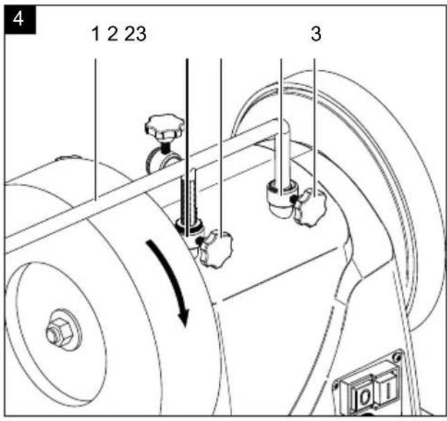
natural_image
Technical line drawing of a mechanical device with rollers and mounting base (no text or symbols)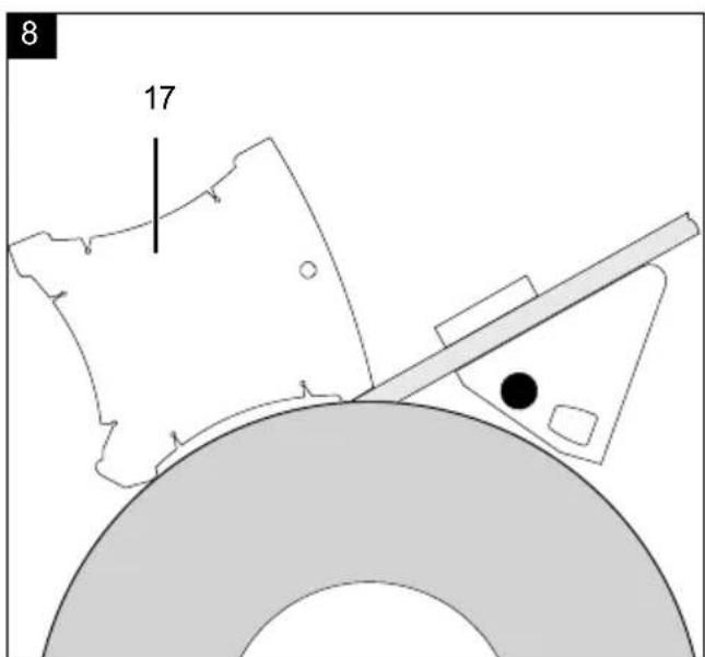

natural_image
Technical line drawing of a mechanical device with rotating components and directional arrows (no text or symbols)Günzburger Straße 69
D-89335 Ichenhausen
Verehrter Kunde
natural_image
Technical line drawing of a mechanical device with labeled components (no readable text or symbols)natural_image
Mechanical assembly diagram showing a rotating wheel and shaft assembly (no text or symbols)natural_image
Technical illustration of a mechanical device with a tool and rotating wheel (no text or symbols)natural_image
Mechanical assembly diagram showing a wheel and mechanical components (no text or symbols visible)natural_image
Mechanical assembly diagram showing a tool interacting with a bracket and housing (no text or symbols visible)natural_image
Technical line drawing of a mechanical component with no visible text or symbolsHomepage: https://www.scheppach.com/de/service
Explanation of the symbols on the device
Symbols are used in this manual to draw your attention to potential hazards. The safety symbols and the accompanying explanations must be fully understood. The warnings themselves will not rectify a hazard and cannot replace proper accident prevention measures.
 | Read the operating and safety instructions before start-up and follow them! |
 | Wear hearing protection! |
 | If dust builds up, wear respiratory protection! |
 | Wear eye protection! |
 | Danger of injury due to a rotating tool! Keep your hands away. |
 | Keep third-parties away from the danger zone. |
 | Protection class II |
 | The product complies with the applicable European directives. |
| △ Attention! | We have marked points in this operating manual that impact your safety with this symbol. |
Table of contents: Page:
- Introduction....23
- Device description 23
- Scope of delivery 23
- Proper use 24
- Safety Instructions....24
- Residual risks 26
- Technical specifications....26
- Before commissioning 26
- Assembly 27
- Operation....28
- Electrical connection 29
- Cleaning and maintenance....30
- Storage and transport.... 30
- Disposal and recycling....30
- Trouble shooting 31
- Special accessories....32
- Declaration of conformity 255
1. Introduction
Manufacturer:
Scheppach GmbH
Günzburger Straße 69
D-89335 Ichenhausen
Dear customer,
we wish you a pleasant and successful working experience with your new scheppach circular wet grinding machine.
Note:
According to the applicable product liability law the manufacturer of this device is not liable for damages which arise on or in connection with this device in case of:
- improper handling,
• non-compliance of the operating instructions, - repairs by third party, non authorized service technicians,
- installation and replacement of non-original spare parts,
- application other than specified,
- failures of the electrical system due to the non-compliance with the electrical specifications and the VDE 0100, DIN 57113 / VDE 0113 regulations.
Recommendations:
Read the entire text of the operating instructions prior to the assembly and operation of the device.
These operating instructions are intended to make it easier for you to get familiar with your device and utilize its intended possibilities of use.
The operating instructions contain important notes on how to work safely, properly and economically with your machine and how to avoid dangers, save repair costs, reduce downtime, and increase the reliability and working life of the machine.
In addition to the safety regulations contained herein, you must in any case comply with the applicable regulations of your country with respect to the operation of the machine.
Put the operating instructions in a clear plastic folder to protect them from dirt and humidity, and store them near the machine. The instructions must be read and carefully observed by each operator prior to starting the work.
Only persons who have been trained in the use of the machine and have been informed on the related dangers and risks are allowed to use the machine. The required minimum age must be met.
In addition to the safety notes contained in the present operating instructions and the special regulations of your country, the generally recognized technical rules for the operation of wood working machines must be observed.
We accept no liability for damage or accidents which arise due to non-observance of these instructions and the safety information.
2. Device description
- Workpiece support
- Upper mount, workpiece support
- Star grip screw
- Leather honing wheel
- Machine housing
- On/off switch
- Rubber feet
- Water tank
- Washer
- Grinding shaft
- Nut
- Grindstone
- Universal device
- Star grip screw for leather honing wheel
- Side mount, workpiece support
- Holder for water tank
- Angle gauge
- Speed control
3. Scope of delivery
- Wet grinding machine
- Grindstone (12)
• Workpiece support (1)
• 2x Star grip screw for workpiece support (3)
• Universal device(13) - Honing compound
- Angle gauge (17)
- Operating manual
4. Proper use
- The grinding machine has been exclusively designed for grinding steel using the offered tool (no hard alloy).
- The machine meets the currently valid EU machine directive.
- The machine has been designed for a one-shift operation, operating factor S1 100%.
- Observe all safety instructions and warnings on the device.
• Make sure that all safety instructions and warnings on the machine always are in a readable state. - Only use the machine if it is in a technically faultless state. Pay attention to the intended use, the safety and dangers and comply with the operating instructions! Immediately repair (or have repair) failures which may affect the safety.
- An element of the intended use is also the observance of the safety instructions, as well as the assembly instructions and operating information in the operating manual.
- The safety, working, and maintenance instructions and the dimensions set forth in the specifications must be observed.
- The applicable regulations for the prevention of accidents and other, generally recognized safety rules must be observed.
- The machine may only be used, maintained or repaired by trained persons who are familiar with the machine and have been informed about the dangers. Unauthorized modifications of the machine exclude a liability of the manufacturer for damages resulting from the modifications.
- The machine may only be used with original accessories and original tools of the manufacturer.
- The machine may only be used in the intended manner. Any other use is considered to be not intended. The manufacturer excludes any liability for resulting damages, the risk is exclusively borne by the user.
Please note that our equipment has not been designed for use in commercial, trade or industrial applications. Our warranty will be voided if the equipment is used in commercial, trade or industrial businesses or for equivalent purposes.
5. Safety Instructions
⚠ WARNING! Read all safety instructions, information, illustrations and technical data for this electric tool. Failure to observe the following information and instructions can result in electric shock, fire and/or serious injuries.
Store all safety instructions and information for future reference.
The term „electrical tool“ used in the safety instructions refers to mains-powered electrical tools (with a mains cable) and battery-powered electrical tools (without a mains cable).
1. Workplace safety
a) Keep your work area clean and well-lit. Disorganised or unlit work areas can result in accidents.
b) Do not work with the electric tool in an explosive environment where flammable liquids, gases or dusts may be located. Electric tools produce sparks that may ignite dust or vapours.
c) Keep children and other people away while using the electric tool. Distractions may cause you to lose control of the electric tool.
2. Electrical safety
a) The connection plug of the electric tool must fit into the socket. The plug may not be modified in any way. Do not use an adaptor plug together with earthed electric tools. Unmodified plugs and suitable sockets reduce the risk of an electric shock.
b) Avoid body contact with earthed surfaces, such as pipes, heaters, ovens and refrigerators. There is an increased risk of electric shock if your body is earthed.
c) Keep your electric tools away from rain and moisture. Water penetrating an electric device increases the risk of an electric shock.
d) Do not use the connection cable for another purpose, for example, carrying or hanging the electric tool or pulling the plug out of the socket. Keep the connection cable away from heat, oil, sharp edges or moving parts. Damaged or coiled connection cables increase the risk of an electric shock.
e) If you work with an electric tool outdoors, only use extension leads that are also suitable for outdoor use. Using an extension lead suitable for outdoor use reduces the risk of an electric shock.
f) If you cannot avoid using the electric tool in a wet environment, use a residual current circuit breaker. Using a fault-current circuit breaker reduces the risk of an electric shock.
3. Safety of personnel
a) Remain attentive, pay attention to what you are doing and be sensible when working with electric tools. Do not use an electric tool if you are tired or under the influence of drugs, alcohol or medication. A moment of carelessness when using electric tools can result in serious injuries.
b) Wear personal protective equipment and always wear safety goggles. Wearing personal protective equipment, such as dust masks, anti-slip safety shoes, safety helmet or hearing protection, depending on the type and use of the electric tool, reduces the risk of injuries.
c) Avoid unintentional startup. Make sure that the electric tool is switched off before you connect it the power supply and/or battery, pick it up or carry it. Keeping your finger on the switch when you carry the electric tool or having the electric tool switched on when you connect it to the power supply may result in accidents.
d) Remove the setting tools or spanners before switching on the electric tool. A tool or spanner that is located in a rotating part of the electric tool may result in injuries.
e) Avoid abnormal posture. Make sure that you have secure footing and always maintain your balance. This will allow you to better control the electric tool in unexpected situations.
f) Wear suitable clothing. Do not wear wide clothing or jewellery. Keep hair and clothing away from moving parts. Loose clothing, jewellery and long hair can be caught by moving parts.
g) If dust extraction and collection devices can be mounted, these must be connected and used properly. Using a dust extraction unit can reduce hazards caused by dust.
h) Do not allow yourself to be lulled into a false sense of security and do not ignore the safety rules for electric tools, even when you have used them many times and have become familiar with them. Careless actions can result in serious injuries within a fraction of a second.
- Using and handling the electric tool
a) Do not overload the electric tool. Use the electric tool intended for your work. The suitable electric tool allows you to work better and more safely in the indicated power range.
b) Do not use an electric tool whose switch is defective. An electric tool that cannot be switched on or off is dangerous and must be repaired.
c) Remove the plug from the socket and/or take out a removable battery before setting the device, changing insertion tool parts or putting the electric tool away. These precautionary measures will prevent the electric tool from starting unintentionally.
d) Keep unused electric tools out of the reach of children. Do not let people use the electric tool who are not familiar with it or who have not read these instructions. Electric tools are dangerous if they are used by inexperienced people.
e) Maintain electric tools and accessories with care. Check whether moving parts function properly and do not get stuck and whether parts are broken or are damaged and thus adversely affect the electric tool function. Have damaged parts repaired before using the electric tool. Many accidents are caused by poorly maintained electric tools.
f) Always keep cutting tools sharp and clean. Carefully maintained cutting tools with sharp cutting edges seize up less often and are easier to guide.
g) Use electric tools, accessories and tool attachment, etc. according to these instructions. Take the working conditions and the activity to be carried out into consideration. Using electric tools for applications other than the intended uses can lead to dangerous situations.
h) Keep the handles and gripping surfaces dry, clean and free of oil and grease. Slippery handles and gripping surfaces prevent safe operation and control of the electrical tool in unforeseen situations.
5. Service
a) Only have your electric tool repaired by qualified specialists and only with original spare parts. This ensures that safety of the electric tool is maintained.
⚠️ ATTENTION! This electric tool generates an electromagnetic field during operation. This field can impair active or passive medical implants under certain conditions. In order to prevent the risk of serious or deadly injuries, we recommend that persons with medical implants consult with their physician and the manufacturer of the medical implant prior to operating the machine.
Safety instructions for table-top grinding machines
a) Do not use damaged tool inserts. Check tool attachments such as grinding discs for chipping and cracks before each use. Once you have checked and used the tool attachment, ensure that you and all other persons in the vicinity remain outside the plane of the rotating tool attachment and allow the device to run for 1 min. at the maximum speed.
Damaged tool attachments usually break during this test period.
b) The permissible rotational speed for tool attachments must be at least as high as the maximum speed cited on the electric tool. Accessories that rotate faster than permitted can break and fly off at high speed.
c) Never grind on the side surfaces of the grinding disc. Grinding on the side surfaces can cause the grinding disc to break and fall apart.
6. Residual risks
The machine has been constructed according to the state of the art and the recognized safety rules. Nevertheless, single residual risks may occur during the operation.
- The rotating grinding wheel may cause injuries of fingers and hands.
- Danger caused by electric current if inappropriate electrical connecting lines are used.
- Before performing setting or maintenance work, release the start button and pull out the power plug.
• Furthermore, non obvious residual risks may exist in spite of all measures taken.
- Residual risks can be minimized by carefully observing the safety instructions and the intended use as well as the entire operating instructions.
- Avoid accidental starting of the machine: the operating button may not be pressed when inserting the plug in an outlet. Use the tool attachment that is recommended in this operating manual.
This is how to ensure that your machine provides optimum performance.
- Keep your hands away from the working area when the machine is in operation.
7. Technical specifications
| Dimensions LxWxH | 380 x 290 x 90 mm |
| Workpiece support ø 12 mm | |
| Grinding stone ∅ 250 x ∅ 12 x 63 mm | |
| Idle-running speed - grinding stone | 90-150 min ^-1 |
| Cutting speed 1,2 - 2 m/s | |
| Weight 11 kg | |
Antrieb
| Motor 230 - 240 V~ / 50 Hz | |
| Input P1 180 W | |
| Motor speed 1 | 1950 - 3250 min ^-1 |
| Operating mode S1 | |
Subject to technical modifications!
Noise & vibration
⚠ Warning: Noise can have serious effects on your health. If the machine noise exceeds 85 dB, please wear suitable hearing protection.
Information about noise level measured in accordance with ISO 4871:
Noise data
| Sound power level L_WA | 107 dB |
| Sound pressure level L_pA | 94 dB |
| Uncertainty K_WA/pA | 3 dB |
8. Before commissioning
- Open the packaging and carefully remove the device.
- Remove the packaging material, as well as the packaging and transport safety devices (if present).
- Check that the delivery is complete.
- Check the device and accessory parts for transport damage.
- If possible, keep the packaging until the end of the warranty period.
- Familiarise yourself with the product by means of the operating manual before using for the first time.
- With accessories as well as wearing parts and spare parts use only original parts. Spare parts can be obtained from your specialist dealer.
- When ordering please provide our article number as well as type and year of manufacture for the product.
ATTENTION!
The device and the packaging are not children's toys! Do not let children play with plastic bags, films or small parts! There is a danger of choking or suffocating!
Before connecting the machine to the mains power, make certain that the data on the type plate matches with the mains power data.
⚠ Warning!
Always ensure that the machine is switched off and disconnected from the power supply before changing the device settings.
- All covers and safety devices must be properly fitted before switching on the device.
• The grindstone must be able to run freely. - Before operating the on/off switch, make sure that the grindstone and honing wheel are correctly mounted and that the moving parts of the device function smoothly. Visually inspect both for defects.
- Replace a damaged or worn grindstone.
9. Assembly
9.1 Installation and setting
Please make sure that your grinding machine stands upright and stable on a solid surface with sufficient lighting.
The machine has no front or rear side. Grinding can take place either with or against the direction of rotation.
Tools required for all assembly / adjustment steps:
- Open-ended spanner 19 mm (not included in the scope of delivery)
The grindstone is not pre-assembled for packaging reasons
⚠ Warning!
Do not connect the device to the power supply until assembly is complete. Failure to do so may result in accidental starting and possibly serious injury.
9.2 Sound test
Check the grindstone for cracks and perform a sound test for crack detection.
- The grindstone must be removed from the machine for the sound test. The grindstone stands upright on the floor. On a hard floor, use a piece of wood as a support. The grindstone must be dry.
- Lightly tap the grinding disc with a non-metallic hammer. A crack-free disc has a high, purely bell-like sound. A disc that has a crack produces a muffled sound. If the grindstone is flawless, it can be fitted.
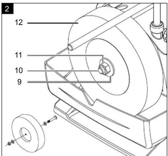
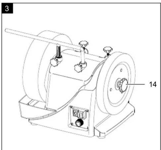
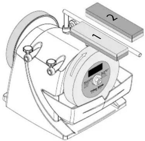
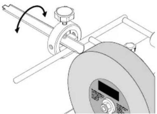
9.3 Installing the grindstone (Fig. 2+3)
Only use grindstones with identical technical data (see 7. Technical data).
- Remove the nut (11) with an open-ended spanner, the outer washer (9) and the cardboard transport sleeve of the grinding shaft (10). To do so, firmly hold the star grip for the leather honing wheel (14). Attention: Left-handed thread.
• The water tank (8) must be removed. (see 9.4) - Place the grindstone on the grinding shaft (10). The inner washer must be behind the grindstone.
• Fit the grindstone (12) as shown in Fig. 2. - Fasten the grindstone with the washer (9) and the nut (11) using an open-ended spanner. To do so, firmly hold the star grip of the leather honing wheel (14). Attention: Left-handed thread.
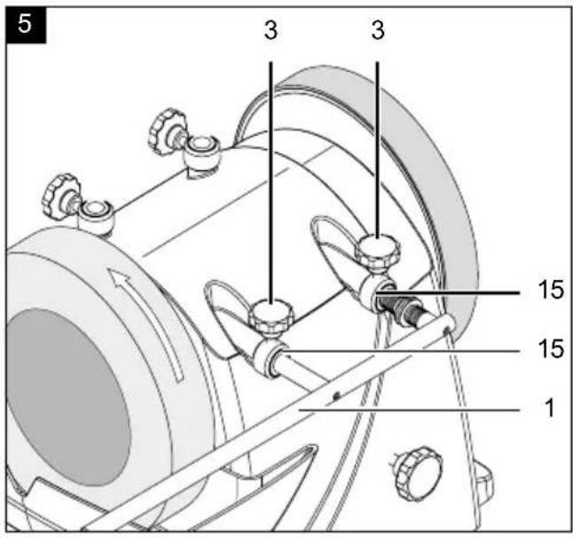
9.4 Fitting the workpiece support (1) (Fig. 4 + 5)
The workpiece support (1) can be attached both to the upper mount for workpiece support (2) and to the side mount for workpiece support (15). This depends on whether you wish to work with or against the grinding direction.
9.4.1 Fitting the upper mount
- To attach the workpiece support (1) to the upper mount for workpiece support (2), first attach the two loose star grip screws (3). Screw them into the upper workpiece support (2) (threaded hole) at the intended position with approx. 2-3 turns.
- Then insert the workpiece support into the holes of the upper mount for workpiece support (2).
- Fasten this at the desired height with the two star grip screws (3).
9.4.2 Fitting the side mount
- The two star grip screws (3) for the side mount for workpiece support (15) are pre-assembled.
- To mount the workpiece support (1) here, insert the workpiece support into the holes in the side mount for workpiece support (15).
- The workpiece support (1) is now fixed for the first step.
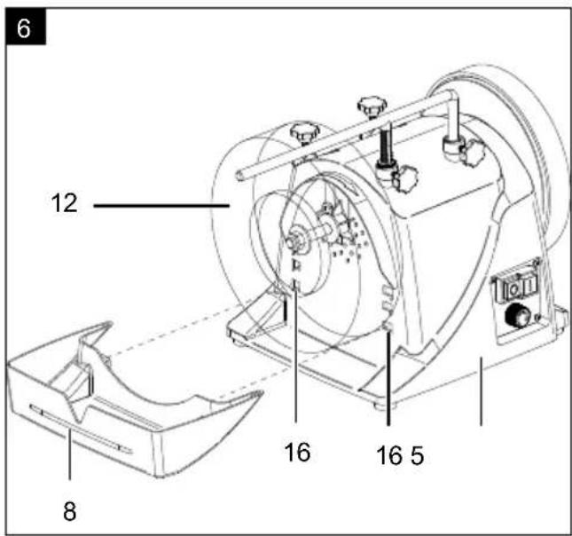
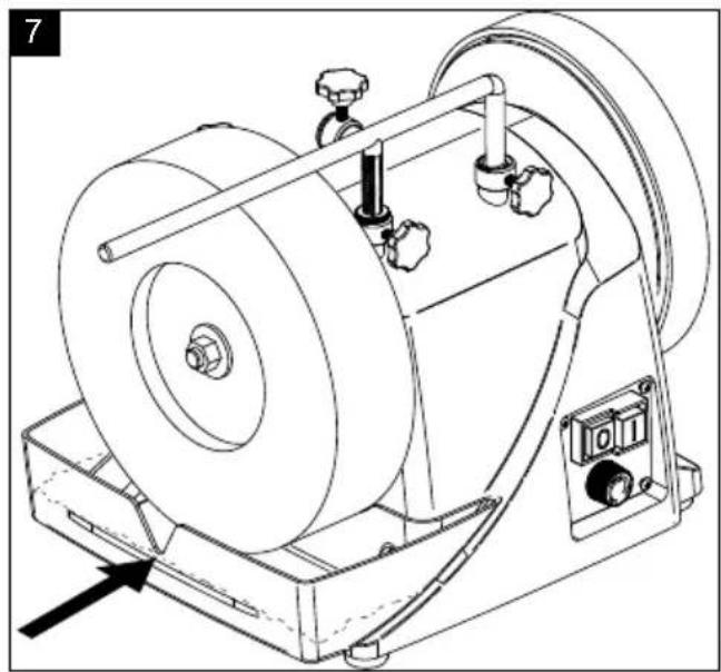
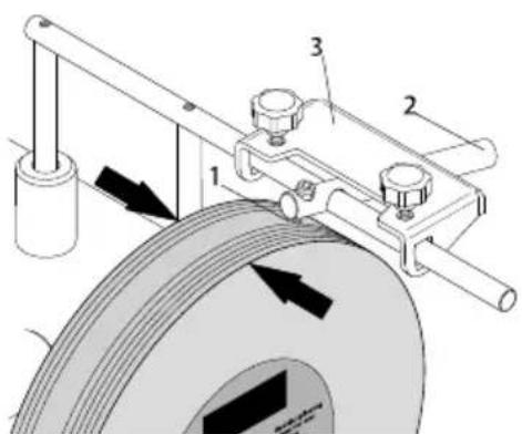
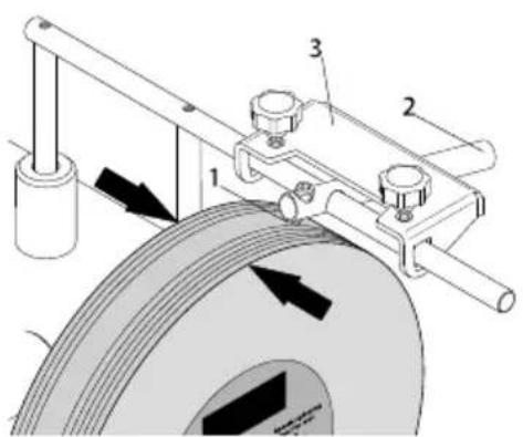
9.5 Installing the water tank (Fig. 6 + 7)
- Attach the water tank (8) in the lowest position to the brackets for the water tank (16) (behind the grindstone) on the machine housing (5). (Fig. 6)
- Then fill the tank with water up to the recess. (Fig. 7)
10. Operation
ATTENTION
Always make sure the device is fully assembled before commissioning!
ATTENTION!
Remove the mains plug before any maintenance, modification and assembly work.
10.1 Grinding direction (Fig. 4 + 5)
This primarily depends on whether you wish to work with or against the grinding direction.
If you wish to remove large quantities of steel quickly (e.g. from very old, rusty tools) or if you want to grind coarse tools such as axes, it is advisable to work against the grinding direction.
If you wish to grind more accurately, we recommend working with the grinding direction. This applies, for example, when grinding tools and blades.
Please note that the grinding process is slowed down when you work with the direction of rotation. Please check before each operation that the surface of the grindstone is flat. To do this, lower the workpiece support onto the stone and turn it manually through 360°. If necessary, break off uneven material with a stone cutter.
10.2 Water tank (Fig. 7)
- Fill the water tank with water up to the recess. The grindstone absorbs water; top up water if necessary.
Do not perform grinding without water. Since the diameter of the grindstone decreases with the number of grinding operations, the grindstone (12) will no longer touch the water in the water tank (8). The grindstone can no longer absorb water. If necessary, the water tank (8) must be placed in the upper holder for the water tank (16). - When the grinding process is complete, lower the water tank to prevent the grindstone from remaining in the water for an extended period of time.
- Empty the water tank regularly. Otherwise steel particles and grinding dust will accumulate in the reservoir and compact.
- Expert tip: Such accumulations can be avoided by placing a magnet in the water.
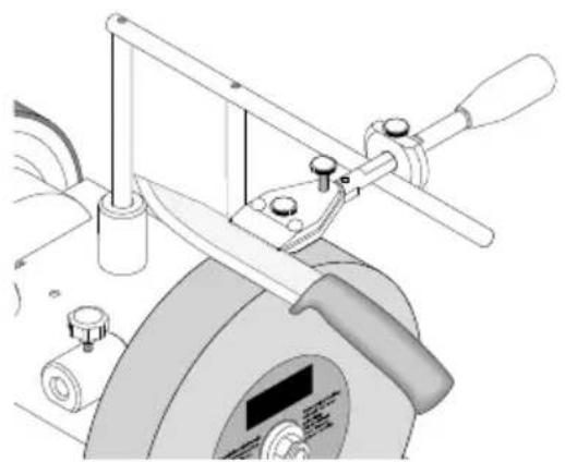
10.3 Angle gauge (Fig. 8)
Measure the angle of the workpiece by comparing the cutting edge with the notches. Then set the determined angle on the device by changing the height of the workpiece support. To do so, perform the following steps:
- First clamp the tool in the device and place the device on the workpiece support
- Then hold the protractor with the desired angle to the tool tip.
- Now adjust the height of the workpiece support so that the front end of the protractor lies directly against the grindstone. Please make sure that the protractor is always aligned with the tool tip.
- Note: The values indicated on the protractor are only guidelines. You can naturally change these values according to your requirements.
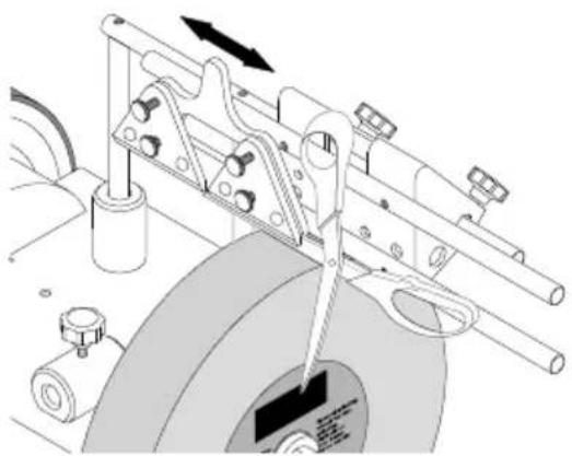
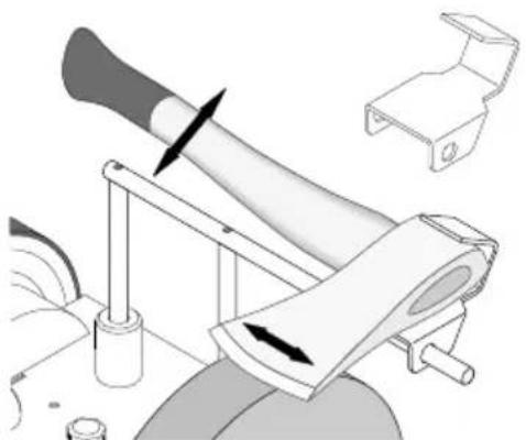
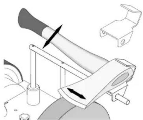
10.4 Grinding (Fig. 9) with the fixture for chisel
Since the grindstone rotates only slowly, it is possible to detect movement in a lateral direction. This is normal and has no negative influence on the grinding result.
Expert tip: New tools still show traces of the production process. You can significantly extend the service life of your tools if you grind them on both sides of the cutting edge before the first use. Simply grind the back in freehand mode on the vertical of the grindstone and the front as follows:
• After you have adjusted the angle, insert the tool mounted in the device into the universal holder, switch on the engine and start the grinding process.
- Press the tool evenly onto the grindstone near the cutting edge and move it laterally across the stone.
- Please make sure that at least half of the cutting edge width is always in contact with the grindstone to avoid damage to the stone.
- To achieve finer grinding results, prepare the stone with a stone preparer. This increases the grain size from 250 to approx. 1000.
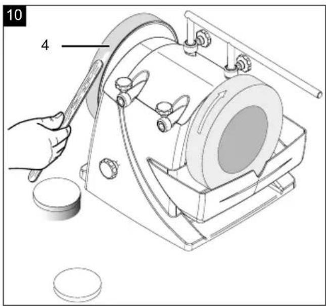
10.5 Honing (Fig. 10)
Never sharpen against the direction of the leather honing wheel! Otherwise the tool will cut into the leather!
- Impregnate the leather honing wheel with machine oil.
- Then apply the grinding paste to the leather honing wheel.
- Switch on the device and spread the grinding paste by pressing the workpiece onto the wheel with circular movements.
• These preparations are sufficient for five to ten tools. - Then start again with a new layer of machine oil, followed by grinding paste. These measures increase the service life of the leather and the quality of your tools.
- Expert tip: You can hone in freehand mode. For a more accurate result, remove the tool with the aid of the appropriate fixture.
10.6 On/off switch (6) (Fig. 1)
• To switch on the machine, press the green "I" button.
- To switch the device off again, press the red button "0".
10.7 Speed controller (18 / Fig. 1)
The speed of the grindstone and of the leather disc can be controlled steplessly using the speed controller (18).
The speed depends on the required result. For grinding, a speed in the lower range is more suitable. For stripping with the leather disc, a higher speed is more suitable.
At high speeds, there is a risk of splashing.
Lower the water container when working with the leather disc at high speeds.
In order to maintain an even grinding speed with a decreasing grindstone diameter, the speed can be adjusted steplessly with the speed controller (18).
| Grinding stoneø mm (inch) | Idle-running speed grinding stone1/min |
| 250 (10") 90-100 | |
| 230 (9") 100-110 | |
| 200 (8") 110-125 | |
| 180 (7") 125-150 |
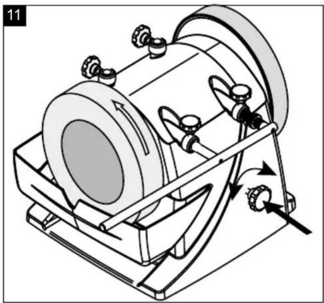
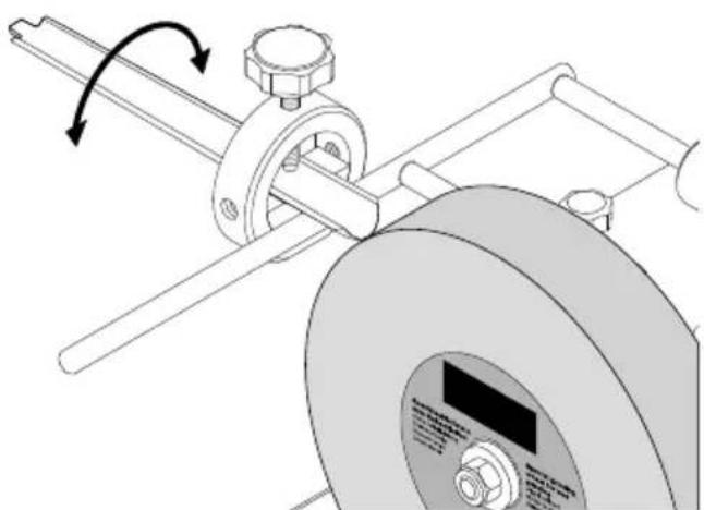
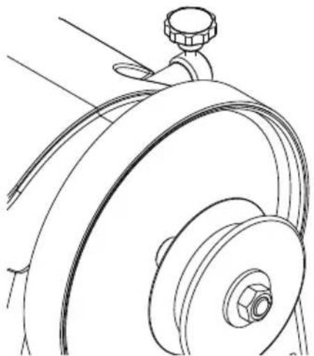
10.8 Friction wheel adjustment with the star grip screw on the rear side (Fig. 13)
- You can adjust the contact pressure on the friction wheel with the star grip screw (23) on the back of the machine housing (see Figure 13). This may be necessary if the leather honing wheel or grindstone stops during sharpening or honing. Turn the star screw clockwise to increase the tension. Tighten the star grip screw only until you feel a slight resistance. Do not over-tighten.
Important:
After working with the machine, the back of the star grip screw (23) must always be loosened counterclockwise so that the engine shaft no longer presses against the friction wheel.
11. Electrical connection
The installed electric motor is connected and is ready to work.
The connection complies with the relevant VDE and DIN regulations.
The connection to the mains supply on the customer side and the used extension line must meet these regulations or the provisions of the local power supply company.
Damaged electrical connection cable
The insulation on electrical connection cables is often damaged.
This may have the following causes:
• Passage points, where connection cables are passed through windows or doors.
- Kinks where the connection cable has been improperly fastened or routed.
- Places where the connection cables have been cut due to being driven over.
• Insulation damage due to being ripped out of the wall outlet.
- Cracks due to the insulation ageing.
Such damaged electrical connection cables must not be used and are life-threatening due to the insulation damage.
Check the electrical connection cables for damage regularly. Make sure that the connection cable does not hang on the power network during the inspection.
Electrical connection cables must comply with the applicable VDE and DIN provisions. Only use connection cables with the marking „H05VV-F“.
The printing of the type designation on the connection cable is mandatory.
A.C. Motor
• The supply voltage must be 230 - 240 V\~ / 50 Hz.
- Extension lines up to a length of 25 m must have a minimum cross section of 1.5 mm ^4 , lines with a length exceeding 25 m must have a minimum cross section of 2.5 mm ^4 .
- The mains connection is protected with a maximum of 16 A.
Connection type Y
If the mains connection cable of this device is damaged, it must be replaced by the manufacturer, their service department or a similarly qualified person to avoid dangers.
Connections and repairs of the electrical equipment may only be performed by an electrician.
If you have further questions, please specify the following:
• Motor manufacturer and type
• Kind of current of the motor
• Data from the machine type plate
• Data of the electric control
If you return the motor, always return the complete drive unit with the electric control.
12. Cleaning and maintenance
⚠ Warning! Switch off the machine and pull out the mains plug before performing setting, maintenance or service work!
Cleaning
Keep all safety devices, ventilation slots and the engine housing free from dirt and dust insofar as possible.
Wipe the device clean with a clean cloth or blow it off with compressed air at low pressure.
We recommend cleaning the device immediately after each use.
Maintenance
The device has no further internal parts that require maintenance.
Service information
Please note that the following parts of this product are subject to normal or natural wear and that the following parts are therefore also required for use as consumables.
Wear parts*: grinding medium, carbon brushes, sharpening wheel, angle gauge, v-belt
* Not necessarily included in the scope of delivery!
Spare parts and accessories can be obtained from our service centre. To do this, scan the QR code on the cover page.
13. Storage and transport
Store devices and accessories out of the reach of children in a dark and dry place above freezing point. The ideal storage temperature lies between 5 and 30 °C. Store the electric tool in its original packaging. Store the grindstone in a cool, dry and dark place.
⚠ Attention! It is essential that the device is secured against falling or tipping over during transport.
The machine may only be lifted and transported by its frame.
14. Disposal and recycling
Notes for packaging

The packaging materials are recyclable. Please dispose of packaging in an environmentally friendly manner.
Notes on the electrical and electronic equipment act [ElektroG]
Waste electrical and electronic equipment does not belong in household waste, but must be collected and disposed of separately!
- Used batteries or rechargeable batteries that are not installed permanently in the old appliance must be removed non-destructively before disposal. Their disposal is regulated by the battery law.
- Owners or users of electrical and electronic devices are legally obliged to return them after use.
- The end user is responsible for deleting their personal data from the old device being disposed of!
- The symbol of the crossed-out dustbin means that waste electrical and electronic equipment must not be disposed of with household waste.
- Waste electrical and electronic equipment can be handed in free of charge at the following places:
- Public disposal or collection points (e.g. municipal works yards)
- Points of sale of electrical appliances (stationary and online), provided that dealers are obliged to take them back or offer to do so voluntarily.
- Up to three waste electrical devices per type of device, with an edge length of no more than 25 centimetres, can be returned free of charge to the manufacturer without prior purchase of a new device from the manufacturer or taken to another authorised collection point in your vicinity.
- Further supplementary take-back conditions of the manufacturers and distributors can be obtained from the respective customer service.
- If the manufacturer delivers a new electrical appliance to a private household, the manufacturer can arrange for the free collection of the old electrical appliance upon request from the end user. Please contact the manufacturer's customer service for this.
• These statements only apply to devices installed and sold in the countries of the European Union and which are subject to the European Directive 2012/19/EU. In countries outside the European Union, different regulations may apply to the disposal of waste electrical and electronic equipment.
15. Trouble shooting
The following table shows fault symptoms and describes remedial measures in the event of your machine failing to work properly. If you cannot localise and rectify the problem with this, please contact your service workshop.
| Problem Possible cause Remedy | ||
| Engine does not run. | Engine, cable or connector defective, fuses burnt. | Have the machine checked by a specialist. Never repair the engine yourself. Attention! Check the fuses and replace them if necessary. |
| The engine starts slowly and does not reach the operating speed. | Voltage too low, coils damaged, capacitor burnt. | Have the power supply company check the voltage. Have the engine checked by a specialist. Have the capacitor replaced by a specialist. |
| Engine producing excessive noise. | Coils damaged, motor defective. | Have the engine checked by a specialist. |
| Engine does not reach full power. | Circuits in the network are overloaded (lamps, other engines, etc.) | Do not use any other devices or engines on the same circuit. |
| Motor overheats easily. | Overloading of the engine, insufficient cooling of the engine. | Avoid overloading the engine during grinding and remove dust from the engine to ensure optimum engine cooling. |
16. Special accessories
natural_image
Technical line drawing of a mechanical device with labeled components (no readable text or symbols)Stone preparer, order no. 8949 0707
Change the graining of your TIGER within seconds from 250 to 1000 and vice versa!
natural_image
Mechanical assembly diagram showing a rotating wheel and shaft assembly (no text or symbols)Device for tubes and gouges (with 100) 55, order no. 8949 0706
You can equip finger-shaped tools with a unique sharpness!

natural_image
Technical illustration of a mechanical tool with a cutting tool and base mount (no text or symbols)Device for small knives 60, order no. 8949 0708
Device for large knives 120, order no. 8949 0709
This way it's pure fun to work in the kitchen!
natural_image
Mechanical assembly diagram showing a wheel-mounted device with attached components and directional arrows (no text or symbols)Device for scissors (with 100) 160, order no. 8949 0710
Now you can easily sharpen all kinds of scissors – whether for paper, cloth or gardening!
natural_image
Mechanical device with lever mechanism and mounting bracket (no text or symbols visible)Device for axes 40, order no. 8949 0712
Cut firewood as fast as never before
– there is no need for huge machines.
Trimming device, order no. 8949 0713
Trimmed within seconds, and you can also polish un-polished metal!
Spare cutting edge, order no. 8949 0714
Just in case.

natural_image
Technical line drawing of a mechanical component with no visible text or symbolsLeather honing disc, profiled, order no. 8949 0705 For the inner side of finger-shaped tools.
Günzburger Straße 69
D-89335 Ichenhausen
Cher client,
natural_image
Technical line drawing of a lathe machine with labeled components (no text or symbols beyond labels)natural_image
Mechanical device with rotating arm and control panel (no visible text or symbols)natural_image
Mechanical assembly diagram showing a cutting tool interacting with a rotating wheel (no text or symbols visible)natural_image
Mechanical assembly diagram showing a wheel and mechanical components with no visible text or symbolsnatural_image
Mechanical device with lever and handle assembly, showing motion arrows (no text or symbols)natural_image
Technical line drawing of a mechanical component with no visible text or symbolsGünzburger Straße 69
D-89335 Ichenhausen
Gentile cliente,
natural_image
Technical line drawing of a mechanical machine with labeled components (no text or symbols beyond labels)natural_image
Mechanical assembly diagram showing a rotating wheel and shaft assembly (no text or symbols)natural_image
Mechanical assembly diagram showing a lathe tool interacting with a rotating wheel and mechanical components (no text or symbols visible)natural_image
Mechanical assembly diagram showing a wheel, shafts, and housing components (no text or labels)natural_image
Mechanical device with lever mechanism and mounting bracket (no visible text or symbols)natural_image
Technical line drawing of a mechanical assembly with no visible text or symbolsGünzburger Straße 69
D-89335 Ichenhausen
Geachte klant,
10.2 Waterreservoir (afb. 7)
natural_image
Technical line drawing of a mechanical machine with labeled parts (no text or symbols beyond numbers)natural_image
Mechanical assembly diagram showing a rotating wheel and shaft assembly (no text or symbols)natural_image
Mechanical assembly diagram showing a lathe tool interacting with a rotating wheel (no text or symbols visible)natural_image
Mechanical assembly diagram showing a wheel and mechanical components with no visible text or symbolsnatural_image
Mechanical assembly diagram showing a tool interacting with a bracket and housing (no text or symbols visible)natural_image
Technical line drawing of a mechanical component with no visible text or symbolsGünzburger Straße 69
natural_image
Technical line drawing of a mechanical device with labeled parts (no readable text or symbols)natural_image
Mechanical assembly diagram showing a rotating wheel and shaft assembly (no text or symbols)natural_image
Mechanical assembly diagram showing a cutting tool interacting with a lathe and rotating wheel (no text or symbols visible)natural_image
Mechanical assembly diagram showing a wheel and mechanical components with no visible text or symbolsDispositivo para tijeras (con 100) 160
natural_image
Mechanical device with lever and handle assembly, no visible text or symbolsnatural_image
Technical line drawing of a mechanical component with no visible text or symbolsGünzburger Straße 69
natural_image
Technical line drawing of a mechanical device with labeled parts (no readable text or symbols)natural_image
Mechanical assembly diagram showing a rotating wheel and mounting bracket (no text or symbols)natural_image
Technical illustration of a mechanical device with a cutting tool and rotating wheel (no text or symbols)natural_image
Mechanical assembly diagram showing a tool interacting with a bearing and rotating components (no text or symbols visible)natural_image
Mechanical assembly diagram showing a tool interacting with a bracket and base, with no visible text or symbols.natural_image
Technical line drawing of a mechanical component with no visible text or symbolsGünzburger Straße 69
D-89335 Ichenhausen
Vážený zákazníku,
natural_image
Technical line drawing of a mechanical device with labeled components (no readable text or symbols)natural_image
Mechanical assembly diagram showing a rotating shaft and wheel assembly with no visible text or symbolsnatural_image
Mechanical assembly diagram showing a cutting tool interacting with a rotating wheel and mechanical components (no text or symbols visible)natural_image
Mechanical assembly diagram showing a tool interacting with a wheel and shaft (no text or symbols visible)natural_image
Mechanical device with lever mechanism and mounting bracket (no text or symbols visible)natural_image
Technical line drawing of a mechanical component with no visible text or symbolsGünzburger Straße 69
D-89335 Ichenhausen
Vážený zákazník,
10.3 Uhlomer (obr. 8)
natural_image
Technical line drawing of a machine with labeled components (no readable text or symbols)natural_image
Mechanical assembly diagram showing a rotating wheel and shaft assembly (no text or symbols)natural_image
Mechanical assembly diagram showing a cutting tool interacting with a rotating wheel and mechanical components (no text or symbols visible)natural_image
Mechanical assembly diagram showing a clamping mechanism with rotating components and directional arrows (no text or symbols)natural_image
Mechanical device with lever mechanism and mounting bracket (no text or symbols visible)natural_image
Technical line drawing of a mechanical component with no visible text or symbolsGünzburger Straße 69
D-89335 Ichenhausen
Tisztelt vásárlónk!
natural_image
Technical line drawing of a mechanical device with labeled components (no readable text or symbols)natural_image
Mechanical assembly diagram showing a rotating wheel and shaft assembly (no text or symbols)natural_image
Mechanical assembly diagram showing a cutting tool interacting with a rotating wheel and mechanical components (no text or symbols visible)natural_image
Mechanical assembly diagram showing a wheel and mechanical components with directional arrows (no text or symbols)natural_image
Mechanical assembly diagram showing a tool interacting with a mechanical component (no text or symbols visible)natural_image
Technical line drawing of a mechanical component with no visible text or symbolsGünzburger Straße 69
D-89335 Ichenhausen
Szanowny Kliencie,
natural_image
Technical line drawing of a machine tool with labeled components (no readable text or symbols)natural_image
Mechanical assembly diagram showing a rotating wheel and shaft assembly (no text or symbols)natural_image
Mechanical assembly diagram showing a cutting tool interacting with a rotating wheel and mechanical components (no text or symbols visible)natural_image
Mechanical assembly diagram showing a wheel and mechanical components with directional arrows (no text or symbols)natural_image
Mechanical assembly diagram showing a tool interacting with a mechanical component (no text or symbols visible)natural_image
Technical line drawing of a mechanical component with no visible text or symbolsGünzburger Straße 69
D-89335 Ichenhausen
Poštovani kupci,
natural_image
Technical line drawing of a mechanical device with labeled components (no readable text or symbols)Gladilo, br. art. 8949 0707
Promijenite veličinu zrna stroja TIGER u nekoliko sekundi, sa 250 na 1000 i obratno!
natural_image
Mechanical assembly diagram showing a rotating wheel and shaft components (no text or symbols)Naprava za cijevi i dlijeta (sa 100) 55, br. art. 8949 0706 Alat u obliku prsta mora imati nenakošenu oštricu!
natural_image
Mechanical assembly diagram showing a cutting tool interacting with a rotating wheel and mechanical components (no text or symbols visible)Naprava za male noževe 60, br. art. 8949 0708
Naprava za velike noževe 120, br. art. 8949 0709
natural_image
Mechanical assembly diagram showing a wheel and mechanical components with no visible text or symbolsNaprava za škare (sa 100) 160, br. art. 8949 0710
Škare za papir, tkaninu ili živicu, sada ih sve možete naoštriti!
natural_image
Technical illustration of a mechanical device with directional arrows indicating movement or force (no text or symbols present)Sklop za odstrugavanje, br. art. 8949 0713
Naoštreno i ponovno okruglo za nekoliko sekundi! Rezervna oštrica, br. art. 8949 0714
Za svaki slučaj.
natural_image
Technical line drawing of a mechanical component with no visible text or symbolsKožni disk za oštrenje, profiliran 100, br. art. 8949 0705
Za unutarnju stranu alata u obliku prsta.
Razlaga simbolov na napravi
Günzburger Straße 69
D-89335 Ichenhausen
Spoštovani kupec,
želimo vam veliko veselja in uspeha pri delu z vašo novo napravo.
Napotek:
natural_image
Technical line drawing of a machine with labeled components (no text or symbols beyond numbers)natural_image
Mechanical assembly diagram showing a rotating wheel and shaft assembly (no text or symbols)Priprava za cevi in žlebila (s 100) 55,
natural_image
Mechanical assembly diagram showing a tool interacting with a wheel and mechanical components (no text or symbols visible)natural_image
Mechanical assembly diagram showing a tire and mechanical components with no visible text or symbolsnatural_image
Mechanical device with lever mechanism and mounting bracket (no text or symbols visible)natural_image
Technical line drawing of a mechanical component with no visible text or symbolsUsnjeni polirni kolut, profiliran 100,
Günzburger Straße 69
D-89335 Ichenhausen
Austatud klient!
natural_image
Technical line drawing of a mechanical device with labeled components (no readable text or symbols)natural_image
Mechanical assembly diagram showing a rotating wheel and mounting bracket (no text or symbols)natural_image
Mechanical assembly diagram showing a cutting tool interacting with a rotating wheel and mechanical components (no text or symbols visible)Seadis väikestele nugadele 60, tellimis-nr 8949 0708 Seadis suurtele nugadele 120, tellimis-nr 8949 0709
natural_image
Mechanical assembly diagram showing a wheel, shafts, and housing components (no text or labels)natural_image
Technical line drawing of a mechanical component with no visible text or symbolsnatural_image
Mechanical assembly diagram showing a tool interacting with a bracket and housing (no text or symbols visible)Günzburger Straße 69
D-89335 Ichenhausen
Gerbiamas kliente,
natural_image
Technical line drawing of a mechanical device with labeled parts (no readable text or symbols)natural_image
Mechanical assembly diagram showing a rotating wheel and shaft assembly (no text or symbols)natural_image
Technical illustration of a mechanical tool with a cutting wheel and lever assembly (no text or symbols)natural_image
Mechanical assembly diagram showing a wheel and mechanical components with directional arrows (no text or symbols)natural_image
Illustration of a mechanical device with a tool and directional arrows, no visible text or symbolsnatural_image
Technical line drawing of a mechanical component with no visible text or symbolsGünzburger Straße 69
D-89335 Ichenhausen
Godātais klient!
natural_image
Technical line drawing of a mechanical device with labeled components (no readable text or symbols)natural_image
Mechanical assembly diagram showing a rotating wheel and connecting rod (no text or symbols)natural_image
Mechanical assembly diagram showing a cutting tool interacting with a lathe and rotating wheel (no text or symbols visible)natural_image
Mechanical assembly diagram showing a wheel, shafts, and mounting components (no text or labels)natural_image
Mechanical assembly diagram showing a tool interacting with a bracket and housing (no text or symbols)natural_image
Technical line drawing of a mechanical component with no visible text or symbolsGünzburger Straße 69
D-89335 Ichenhausen
Bästa Kund!
natural_image
Technical line drawing of a mechanical device with labeled components (no text or symbols beyond labels)natural_image
Mechanical assembly diagram showing a rotating wheel and shaft assembly (no text or symbols)natural_image
Mechanical assembly diagram showing a cutting tool interacting with a rotating wheel and mechanical components (no text or symbols visible)natural_image
Mechanical assembly diagram showing a wheel and mechanical components with directional arrows (no text or symbols)natural_image
Mechanical assembly diagram showing a tool interacting with a mechanical component (no text or symbols visible)natural_image
Technical line drawing of a mechanical component with no visible text or symbolsGünzburger Straße 69
D-89335 Ichenhausen
Arvoisa asiakas
natural_image
Technical line drawing of a mechanical device with labeled parts (no readable text or symbols)natural_image
Mechanical assembly diagram showing a rotating wheel and shaft assembly (no text or symbols)natural_image
Mechanical assembly diagram showing a cutting tool interacting with a lathe (no text or symbols visible)Laite pienille terille 60,
Tilausnro. 8949 0708
natural_image
Mechanical assembly diagram showing a wheel and mechanical components with no visible text or symbolsnatural_image
Illustration of a mechanical device with a tool and lever mechanism (no text or symbols)Laite kirveille 40, tilausnro. 8949 0712
natural_image
Technical line drawing of a mechanical component with no visible text or symbolsGünzburger Straße 69
D-89335 Ichenhausen
Kære kunde,
natural_image
Technical line drawing of a mechanical device with labeled parts (no readable text or symbols)natural_image
Mechanical assembly diagram showing a rotating wheel and shaft assembly (no text or symbols)natural_image
Mechanical assembly diagram showing a cutting tool interacting with a rotating wheel and mechanical components (no text or symbols visible)natural_image
Mechanical assembly diagram showing a tire and mechanical components with no visible text or symbolsIndretning til sakse (med 100) 160,
natural_image
Mechanical assembly diagram showing a tool interacting with a mechanical bracket (no text or symbols visible)Indretning til økser 40, bestil-nr. 8949 0712
Afdrejningsindretning, bestil-nr. 8949 0713
natural_image
Technical line drawing of a mechanical component with no visible text or symbols
EC Declaration of Conformity
Standard references:
EN 55014-1:2017; EN 55014-2:2015; EN IEC 61000-3-2:2019; EN 61000-3-3:2013
This declaration of conformity is issued under the sole responsibility of the manufacturer.
The object of the declaration described above fulfils the regulations of the directive 2011/65/EU of the European Parliament and Council from 8th June 2011, on the restriction of the use of certain hazardous substances in electrical and electronic equipment.
Subject to change without notice
Documents registrar: Dawid Hudzik
Günzburger Str. 69, D-89335 Ichenhausen
Garantie DE
Apparent defects must be notified within 8 days from the receipt of the goods. Otherwise, the buyer's rights of claim due to such defects are invalidated. We guarantee for our machines in case of proper treatment for the time of the statutory warranty period from delivery in such a way that we replace any machine part free of charge which provably becomes unusable due to faulty material or defects of fabrication within such period of time. With respect to parts not manufactured by us we only warrant insofar as we are entitled to warranty claims against the upstream suppliers. The costs for the installation of the new parts shall be borne by the buyer. The cancellation of sale or the reduction of purchase price as well as any other claims for damages shall be excluded.
Garantie FR
Apparent defects must be notified within 8 days from the receipt of the goods. Otherwise, the buyer's rights of claim due to such defects are invalidated. We guarantee for our machines in case of proper treatment for the time of the statutory warranty period from delivery in such a way that we replace any machine part free of charge which provably becomes unusable due to faulty material or defects of fabrication within such period of time. With respect to parts not manufactured by us we only warrant insofar as we are entitled to warranty claims against the upstream suppliers. The costs for the installation of the new parts shall be borne by the buyer. The cancellation of sale or the reduction of purchase price as well as any other claims for damages shall be excluded.
Záruka CZ
Apparent defects must be notified within 8 days from the receipt of the goods. Otherwise, the buyer's rights of claim due to such defects are invalidated. We guarantee for our machines in case of proper treatment for the time of the statutory warranty period from delivery in such a way that we replace any machine part free of charge which provably becomes unusable due to faulty material or defects of fabrication within such period of time. With respect to parts not manufactured by us we only warrant insofar as we are entitled to warranty claims against the upstream suppliers. The costs for the installation of the new parts shall be borne by the buyer. The cancellation of sale or the reduction of purchase price as well as any other claims for damages shall be excluded.