Slik 5.0c - Grinder SCHEPPACH - Free user manual and instructions
Find the device manual for free Slik 5.0c SCHEPPACH in PDF.

User questions about Slik 5.0c SCHEPPACH
0 question about this device. Answer the ones you know or ask your own.
Ask a new question about this device
Download the instructions for your Grinder in PDF format for free! Find your manual Slik 5.0c - SCHEPPACH and take your electronic device back in hand. On this page are published all the documents necessary for the use of your device. Slik 5.0c by SCHEPPACH.
USER MANUAL Slik 5.0c SCHEPPACH
| Cathode Subunit | Cathode Type 1, Type 2 |
| Instrumental Subunit name |

Arl Nr.
1903401901
1903401550 | 122212

natural_image
Industrial machine with control panel and coiled tubing (no visible text or symbols)

natural_image
Four-panel technical illustration showing mechanical assembly and alignment (no text or symbols visible)
flowchart
graph TD
    A["电源"] --> B["变压器"]
    B --> C["地"]
    C --> D["开关"]
    D --> E["输出"]
    style A fill:#f9f,stroke:#333
    style B fill:#ccf,stroke:#333
    style C fill:#cfc,stroke:#333
    style D fill:#fcc,stroke:#333
    style E fill:#cff,stroke:#333
Hersteller:
Scheppach
Günzburger Straße 69
D-89335 Ichenhausen
Verehrter Kunde,
Günzburger Straße 69
D-89335 Ichenhausen
Dear customer,
we wish you a pleasant and successful working experience with your new machine.
Note:
According to the applicable product liability law the manufacturer of this device is not liable for damages which arise on or in connection with this device in case of:
- improper handling
• non-compliance with the instructions for use
• repairs by third party, non authorized skilled workers - installation and replacement of non-original spare parts
- improper use
- failures of the electrical system due to the non-compliance with the electrical specifications and the VDE 0100, DIN 57113 / VDE 0113 regulations
Recommendations:
Read the entire text of the operating instructions prior to the assembly and operation of the device.
These operating instructions are intended to make it easier for you to get familiar with your device and utilize its intended possibilities of use.
The operating instructions contain important notes how to work safely, properly and economically with your machine and how to avoid dangers, save repair costs, reduce downtime, and increase the reliability and working life of the machine.
In addition to the safety regulations contained herein, you must in any case comply with the applicable regulations of your country with respect to the operation of the machine. Put the operating instructions in a clear plastic folder to protect them from dirt and humidity, and store them near the machine. The instructions must be read and carefully observed by each operator prior to starting the work. Only persons who have been trained in the use of the machine and have been informed on the related dangers and risks are allowed to use the machine. The required minimum age must be met.
General Notes
- When you unpack the device, check all parts for possible transport damages. In case of complaints the supplier is to be informed immediately. Complaints received at a later date will not be acknowledged.
- Check the delivery for completeness.
- Read the operating instructions to make yourself familiar with the device prior to using it.
- Use only original parts for accessories as well as for wearing and spare parts. Spare parts are available from your specialized scheppach dealer.
- Specify our part numbers as well as the type and year of construction of the device in your orders.
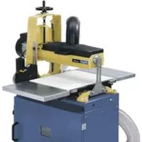
Slik 5.0c
| Scope of delivery | |
| Drum Sander | |
| Adapter Table | |
| Base | |
| Handle for Height Adjustment | |
| Crank for Height Adjustment | |
| 2 Extension Tables | |
| Bow - Suction Connection | |
| Operating Instructions | |
| Specifications | |
| DimensionsL x W x H mm | 1005 x 850 x 670 |
| Height of sanding min./max. mm | 2,5/130 |
| Width of sanding max. mm | 405 |
| Table height with stand mm | 720 |
| Sanding belt length/ width mm | 2400/77 |
| Sanding surface with table mm | 420 |
| Sanding belt coarseness | 80 / 120 / 240 |
| Belt speed m/sec | 9,68 |
| ø Suction nozzles mm | 100 |
| Weight kg | 83,0 |
| Drive | |
| Motor V/Hz | 230-240V/50 Hz |
| Input P1 kW | 2,00 |
| Output P2 kW | 1,50 |
| Rotational speed rpm | 1400 |
| Undervoltage release | yes |
| Plug | Netzstecker |
| Operating mode | S6 40% |
| Subject to technical modifications! | |
Noise parameters according to EN 23746
The noise emission values determined according to EN 23746 for the sound power level or according to EN 31202 (correction factor k3 calculated according to Annex A.2 of EN 31204) for the sound level at the work place are based on the working conditions specified in ISO 7960 Annex A and are as follows:
Sound power level at the work place in dB
Idle running L_WA = 77.0 dB(A)
Processing L_WA = 87.0 dB(A)
Sound level at the work place in dB
Idle running L_pAeq = 69.0 dB(A)
Processing L_pAeq = 77.0 dB(A)
A measuring incertainty allowance K=4 dB applies for the specified emission values.
Specifications regarding the dust emission
The dust emission values that were measured according to the “Principles for the evaluation of the dust emission (concentration parameters) of wood working machines” of the Fachausschuss Holz (Expert committee wood) are below 2 mg/m ^3 . Thus, it can be assumed that the TRK limit value for wood dust applicable in the Federal Republic of Germany is permanently and reliably fallen short of when the machine is connected to a proper operational suction plant with an air speed of at least 20 m/s.
Please observe the load values of the material manufacturer depending on the materials to be processed or the material quality.
In these operating instructions we have marked the places that have to do with your safety with this sign: ⚠
⚠️ General Safety Rules
When using electric tools basic safety precautions should always be followed to reduce the risk of fire, electric shock and personal injury.
- Keep guards in place and in working order.
- Remove adjusting keys and wrenches. Form the habit of checking to see that keys and adjusting wrenches are removed from the machine before turning it on.
- Keep the working area clean. Cluttered areas and benches invite accidents.
- Don't use in a dangerous environment. Don't use power tools in damp or wet locations, or expose them to rain. Keep work area well lighted.
- Keep children away. All visitors should be kept at a safe distance from the work area.
- Make your workshop kid proof. Lock your workshop. Tools not used should be kept in a dry place, inaccessible for children.
- Don't force the tool. It will do the job better and safer at the rate for which it was designed.
- Use the right tool. Don't force the tool or attachment to do a job for which is was not designed.
- Use proper extension cord. Make sure your extension cord is in good condition. When using an extension cord, be sure to use one heavy enough to carry the current your product will draw. An undersized cord will cause a drop in voltage resulting in loss of power and overheating.
- Wear proper clothing. Do not wear loose clothing, gloves, neckties, rings, bracelets, or other jewelry which may get caught in moving parts. Nonslip shoes are recommended. Wear protective hair covering to contain long hair. Roll your sleeves up to above the elbows.
- Protect your eyes by safety goggles. Everyday eyeglasses offer only little protection. They are no safety glasses. Wear a face or dust mask when working in a dusty environment.
- Secure work. Use clamps or a vice to hold work, when practical. It is safer than using your hand, and it frees both hands to operate the tool.
- Don't overreach. Keep proper footing and balance at all times.
- Maintain tools with care. Keep tools sharp and clean for best and safest performance. Follow the instructions for lubricating, and changing accessories.
- Always disconnect the machine before servicing, and when changing accessories, such as blades, bits, cutters, and the like.
- Only use recommended accessories. Consult the operating instructions for the recommended accessories. The use of improper accessories may cause risk of injury to persons.
- Never stand on the machine. Serious injury could occur if the machine is tipped or if the cutting tool is unintentionally contacted.
- Check for damaged parts. Before further use of the tool, a guard or other part that is damaged should be carefully checked to determine that it will operate properly and perform its intended function. Check for alignment or binding of moving parts, breakage of parts, mounting, and any other conditions that may affect its operation. A guard or other part that is damaged should be properly repaired or replaced.
- Direction of work. Push the workpiece towards the sawblade or cutter only in the moving direction of the tool.
- Never leave the machine unattended while it is running. Wait until the tool has come to an absolute standstill, before you leave the machine.
- Use the correct power connection. Do not pull the power plug to stop the machine during work. Never remove the plug from the socket by pulling the extension cord.
- Always stay attentive to what you are doing, even when using the machine regularly. Bear in mind that a fraction of a second is sufficient to cause an injury.
- Keep your safety in mind. Safety is a combination of common sense and staying alert as long as the machine is switched on.
Additional Safety Regulations for the Cylinder Sanding Machine
- WARNING: Do not use your machine until it is completely assembled and installed according to the instructions.
- If you are not familiar with the operation of the sanding machine, ask the head of the department, your teacher, or any other qualified person.
- ATTENTION: This machine has only been designed for sanding wood or similar materials. The sanding of other materials can cause fire, injuries, or damage the product.
• Always wear safety goggles.
- This machine may only be operated indoors.
- IMPORTANT: Mount and use the machine on a horizontal surface. A non-horizontal surface can damage the motor.
- If the machine tends to tilt or walk (especially when sanding long and heavy panels), it must be fastened to a solid surface of sufficient carrying force.
- If you are working with larger work pieces, you should use extra support at the height of the table.
- Never use this machine, if the cylinder dust cap or the motor protective equipment is missing. Never sand deeper than 0.8 mm at one time.
- Do not sand work pieces that are shorter than 76 mm or narrower than 19 mm. Make sure that you have the correct relationship between the entry and the exit areas, and the path to the sanding cylinder. Be sure that the work piece is adequately fixed during the whole time it is being sanded.
- Keep control at all times of your work. Do not lean the work piece against the entry table.
- Do not try to carry out an unusual or uncommon work process without fixing the work piece appropriately, and before you really understand how the process works.
- Before turning on the motor, check that the adjustments and all clamping devices and screws are assure the correct and firm positioning.
- Always turn off the motor and pull out the plug, before you attempt any adjustments or change the sanding belts.
- Turn off the machine after roughly fifty hours of operation and check that the motor and the cylinder screws as well as the screws on the entry rolls are fully tightened.
- Do not force a work piece into the machine. Allow the sanding machine to work at its own speed.
- Occasionally check the entry belts, to make sure that there is no waste or sawdust among the components.
- Only sand intact wood. There should be no loose knotholes and few knotholes in general. Make sure that the work piece is free of nails, screws, stones or other alien elements that could damage the sanding cylinder or the sanding belt.
- Never stand in the direct line of the sanding band, on the entry or the exit side. Position yourself to the side of the machine.
- Make sure that the sanding belt is positioned as described in the operating instructions. A belt that is not tightened correctly may loosen during operation and damage either the work piece or the internal machine components.
- Never put your fingers into the dust exit or under the cylinder's dust cover. Wait to start sanding until the cylinder has reached full speed.
- Turn the machine off, and pull the plug out of the socket, when you install accessories or remove them.
- Never leave the work area, when the machine is turned on or not completely at a standstill.
⚠️ Proper Use
The machine meets the currently valid EU machine directive.
- The safety, working, and maintenance instructions and the dimensions set forth in the specifications must be observed.
- The applicable regulations for the prevention of accidents and other, generally recognized safety rules must be observed.
- The machine may only be used, maintained or repaired by trained persons who are familiar with the machine and have been informed about the dangers. Unauthorized modifications of the machine exclude a liability of the manufacturer for damages resulting from the modifications.
- The machine may only be used with original accessories and original tools of the manufacturer.
- Any other use is considered to be not intended. The manufacturer excludes any liability for resulting damages, the risk is exclusively borne by the user.
⚠️ Residual Risks
The machine has been constructed according to the state of the art and the recognized safety rules. Nevertheless, single residual risks may occur during the operation.
- Risk of injuries for fingers and hands caused by the rotating grinding roller in the case of an improper guidance or support of the work piece to be ground.
- Risk of injury caused by hurling work pieces in case of an improper support or guidance.
- Danger caused by electric current if inappropriate electrical connecting lines are used.
- Furthermore, non obvious residual risks may exist in spite of all measures taken.
- Residual risks can be minimized by carefully observing the Safety Notes and the Intended Use as well as the entire operating instructions.
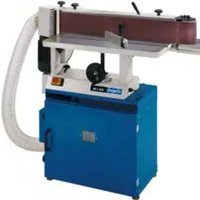
Equipment Fig. 1
1 Cylinder with dust cover
2 Cylinder drive motor
3 Transport motor for grinding belt
4 On/Off switch for variable speed
5 Extension tables
6 Height adjustment
7 Extraction nozzle
8 Adapter plate
9 Feeding transport belt
10 Guide skid
11 On/Off switch
Unpacking the Machine
Carefully remove all the pieces from the delivery carton. Do not throw away any of the packing materials, until you have found all of the parts listed on the accompanying parts list.
If a piece is missing, please ask your dealer to send it to you.
Inspect all parts in order to make sure that nothing has been damaged in transport. You must replace damaged parts before attempting to work with the machine.
Assembly
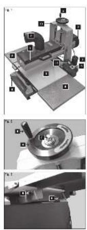
Height Adjustment Crank Fig. 2
After unpacking your sanding machine and checking the parts list for any missing components, you can mount the handle (B) for height adjustment.
Screw the height adjustment handle into the thread on the height adjustment crank (A). Use a slotted screwdriver and tighten the handle until it is firmly fixed in place.
Place the crank above the axle, so that the bolt with the latching wedge aligns with the height adjustment axle. Then secure it with the washer and dome nut (C).
Assembling the Extension Table, Fig. 3
Tighten by hand the extension table, on both sides, with the screws (D), adjust the transport band and tighten it.
We recommend affixing the machine to the base with which it is delivered.
Four screws are included for this purpose.
Adjustment
Your sanding machine was aligned and completely adjusted when it was assembled. The effects of transport may make it necessary to adjust the unit or to align it, or to return it for this work. It is very important that the following adjustments, as described below, be made.
- Warning: Never make adjustments when the machine is plugged in. Ignoring this warning can lead to serious injury.
- Warning: Always attach the machine to a workbench or a base, in order to prevent it from tipping or moving about on the table. Ignoring this warning can lead to serious injuries.
Sanding Cylinder Play, Fig. 4
Before you begin adjustments to the sanding cylinder, as described in the following, make sure that the sanding cylinder has minimal play upwards. The three most important reasons for excessive play are:
1 Too large a sanding depth. Reduce the sanding depth in order to reduce the pressure on the sanding cylinder unit. See the directions about the sanding depth in the section „Introduction to Cylinder Sanding“.
2 Loose height adjustment screws -- see the directions about the cut depth in the section on cylinder adjustment.
3 Loose attachment screws in the motor or cylinder unit -- see Fig. 4. Check that the four screws are tightened, two above and two below, and if necessary tighten them.
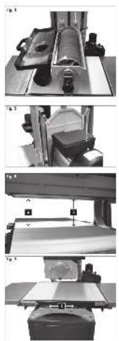
Adjustment of the Cylinder, Fig. 5, 6, 7, 8
- Warning: In order to avoid serious injury, always unplug the sanding machine before you begin maintenance or adjustment work.
1 Check that the positioning screws for the hoisting tension (Fig. 5) are correct. These screws must be adjusted to make the height adjustment possible and also to limit the play of the cylinder. (If the screws are too loose, then the cylinder has too much play during sanding and this can make the surface uneven. If the screws are too tight, then it is difficult to make height adjustments.)
2 In order to position the height adjustment screws, loosen the safety nuts, which hold the screws in place. Loosen the screws as necessary a quarter of a turn or tighten them to achieve the desired level of tightness and smooth functioning. Tighten the safety nuts again in order to fix the screws' position.
3 Check the alignment of the sanding cylinder and the transport table. To do this, first remove the sanding belt from the cylinder. The goal of this adjustment is to maintain the same distance between points A and B, which, in turn, ensures that the cylinder is parallel to the entry table and thus allows even sanding (see Fig. 6).
If the distance A is 0.5 mm or less/larger than the same point at B, proceed as follows:
1 Loosen the two outside fastening screws (C) on the transport table, as shown in Fig. 7.
2 As necessary, push one or both of the spacers under the edge of the transport table.
3 Tighten the fastening screws on the transport table. Check once again the measurements at A and B.
4 Make a test run and check that the machine produces an even thickness. Repeat this procedure as often as necessary.
If the measurement B is 0.5 mm larger than at the same point in A, proceed as follows:
1 Loosen the two outside fastening screws (C) on the transport table, as shown in Fig. 8.
2 As necessary, push one or both of the spacers under the edge of the transport table.
3 Tighten the fastening screws on the transport table. Check, once again, the measurements at A and B.
4 Make a test run and check that the machine produces an even thickness. Repeat this procedure as often as necessary.
Positioning of the Transport Band and Tracks, Fig. 9
Due to the stretching of the band, occasional adjustment of the transport band tracks may be necessary.
1 The screws for the transport band and track adjustment are to be found on the front and back of the machine (see Fig. 9).
2 In order to increase the track tension, the track screw must be turned clockwise, while the nut is held with an 11 mm wrench (not included). In order to reduce the track tension, the track screw must be turned counter clockwise, while the nut is held with a wrench.
3 If the transport band track veers towards the inside (motor side) of the machine, then the tension on the fixing screw must be increased on this side of the machine.
Note:
Due to the width of the transport band, it is possible that a misalignment of the track is not at once evident. Increase the speed of the transport band in order to be able to monitor the effect of any adjustments. Make small corrections, of roughly a quarter of a turn, and check the results. Adjust as necessary, until the bands run correctly.
Helpful Note:
Tighten the desired track direction on the opposite side. That is, tighten the right side of the track adjustment so that the band runs to the left.
Introduction to Sanding
Function
Cylinder sanding is a repeated sanding procedure on both sides of a wooden work piece, until the desired size and/or smoothness is achieved. When this is carried out correctly, both sides of the work piece run parallel to each other.
Do not confuse cylinder sanding with planing. Depending on the coarseness, hardness of the work piece and width of the work piece, cylinder sanding removes material to 0.8 mm or less. In the case of a portable planing machine, on the other hand, one run through of the material removes up to 3.2 mm. If you can work with a planing machine, in order to smooth and plane your work piece to the size you want to attain, then you will be able quickly to learn how to work with your sanding machine and not against it. Be patient and let the cylinder sander do its work so that you can achieve the best results by removing 0.8 mm or less.
The most usual mistake when using a cylinder-sanding machine is trying to use force to remove too much material too quickly. Many variables (coarseness of the sand paper, width of the wood, the kind of wood, entry speed and wood moisture content) can influence how much material can be removed in a single pass.
Advantages of Cylinder Sanding
One advantage of a cylinder-sanding machine is that, due to its open construction, work pieces up to a width of 81 cm can be handled. Although you must still always sand with the grain, you do not need to read the grain direction in order to avoid ripping. This is especially important for thin work pieces, or for pieces with twisted or mixed grain, for example with a striped pattern.
Cylinder sanding machines put much less pressure on the wood than planing and thus give the operator the possibility of working with material as thin as veneers and thus expands his or her range of operations. Short pieces of wood, unusual forms and head wood can be sanded.
Removing Crosswise Bends in Wood
The best machine to remove cross warps in wood is a planing machine. The limited pressure applied by a sanding machine, nonetheless, can remove warps, because the wood does not lie flat on the entry band and it is not pressed against the table. Be patient. Depending on the depth of the cross warps, in the wood, this procedure can take some time. Lead the work piece into the machine, with the peak of the cross warp upwards (so that the edges rest on the band), and use a coarse grade of sandpaper. Repeat the procedure until the crown is flat on one side. Turn the work piece over and sand it flat.
Do not be surprised at how thin the wood is, after all of the warps have been removed.
Ridges and bends in the wood can not be removed from wood with a cylinder-sanding machine -- and not with a planing machine either, of course. Before starting sanding, check the wood for ridges and bends, because these can easily be caught in the machine. Short pieces of wood are particularly difficult in this aspect.
Plane Your Work Piece First
Planing reduces the time you will need for adjustment and sanding and also the operator's level of frustration. Sort your work pieces according to their thickness and the coarseness of sandpaper that needs to be used. Begin with the thickest material and work through to the thin-nest. Then change to the next, finer grade of, sandpaper and begin the procedure again.
We suggest that you experiment with various coarsenesses and kinds of wood to find out what kind of results you can achieve before you ruin a piece of wood. When new adjustments to the machine are made, be sure to make a test run with scrap material before beginning work.
Kinds of Wood That Require Caution
Wood that has a large amount of resin can quickly clog the sanding paper and in many cases, the material that collects cannot be removed with the belt cleaning brushes. This is particularly often the case with some kinds of pine. It is almost impossible to free the sanding belt from the combination of sap and sawdust.
Use care with those kinds of woods with poisonous characteristics, such as members of the tulipwood family. In spite of dust-suction, small particles can be breathed in with the room air and cause allergic reactions. For extra protection, wear a mask and gloves when working with this kind of wood.
Start Up
Warning: Never put your fingers in the dust exhaust or under the cylinder cover.
Attention: In order to avoid damage to your machine, during operation an adequate dust-suction mechanism must be attached.
Adjustment of the Cylinder Height
The cylinder moves slightly upwards, if the height adjustment (see Fig. 2) is turned in a clockwise direction. It moves downwards, if the height adjustment is turned in a counter clockwise direction. A movement of 0.4 mm corresponds roughly to a quarter turn in each direction. A complete turn thus corresponds to 1.6 mm. The depth adjustment can be read on the scale on the right side of the cylinder frame.
Please note:
When adjusting the depth for the surface sanding, the following variables should be taken into account: material hardness, width of the work piece and the selected intake speed. All these criteria are to be considered, in order to calculate the amount of material to be removed on each through pass. Never remove more than 0.8 mm on a single pass. The variable intake speed is adjusted in order to avoid burning and to produce a smoothly sanded surface in various kinds of wood and for different widths.
As a general rule, a quarter turn or 0.4 mm or less for coarser sandpaper and softer kinds of wood is recommended, while an eighth of a turn or 0.2 mm is recommended for harder woods and/or finer paper. When determining the intake speed for the material to be sanded, the rule is that the broader the material is the slower the selected intake speed should be. Equally, the intake speed should be slower for harder types of wood.
A certain amount of experimentation and practice is needed in order to become confident with the sanding performance of your machine. While surface sanding is similar to surface preparation with a planing machine, the planing machine, due to its special type of cutting edges, remove much more material with each pass. The sanding machine, on the other hand, removes a limited amount of material with the sanding medium.
Sanding
1 While the machine is still turned off, place the work piece on the entry table and push it so far forward that the height of the cylinder can be adjusted. This means the wood is to be positioned so that a uniform thickness is attained at the highest point of the work piece.
2 Close the dust-suction unit and turn this on.
3 Adjust the entry speed, according to the sanding requirements and the width of the materials.
4 Turn the machine on, place the work piece on the transport table and let the cylinder start sanding. Support a long work piece while it is being sanded, if necessary. As soon as the sanding process allows, move to the exit side of the machine, in order to catch the wood and to support it as it leaves the machine.
Note: Do not put any pressure on from the top or the bottom, when leading the work piece through the machine. If you do, you may leave marks on the sanded wood.
5 If the wood is passed through the machine several times, turn it around, while you adjust the depth of sanding with the handle (see Fig. 2). There are many variables that influence the depth chosen for sanding. These include the choice of sandpaper grain, the width of the wood, intake speed and the moisture content of the work piece.
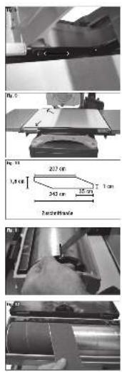
Replacing the Sanding Belt, Fig. 10, 11, 12, 13
Warning: in order to avoid serious injury, always unplug the machine before doing any maintenance work or changing the sanding belts.
Pre-sized sanding belts, which do not require any measurement or cutting, can be bought from your dealer. These belts are conically shaped at the end. They are radially wrapped round the cylinder to create an endless strip. You can also cut your own belts to the correct size from a large roll. To do this, use the belts included in the delivery as a pattern.
1 Make sure that the switch is on OFF and the plug is pulled out.
2 Fig. 10 shows the sanding belt pattern.
3 Take either a pre-cut or a self-cut belt and begin the installation by putting the conical point in the slit on the left side of the cylinder while pushing the clip down (Fig. 11). Roughly, 25 mm of the material should be put into the slit, in order to connect it to the sanding clip. Release the clip, once the conical end is positioned firmly in the clip back. Note: You can use the worn out belts as a pattern to cut new belts.
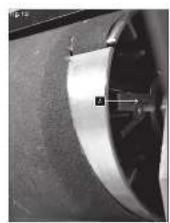
4 Once the sanding belt is positioned firmly in the clip, stand in front of the machine and wind it radially round the cylinder. Turn the cylinder, with your right hand, away from your body and draw the material around the cylinder. Use this technique to wrap the sanding belt radially from edge to edge of the cylinder. Make sure when wrapping it round, that the sanding material does not overlap (Fig. 12). It should be smooth with a small gap but should not overlap while it is being wound around the head.
5 Once the cylinder is completely wrapped, maintain tension on the belt and lead the rest of the conical end into the cylinder slit. Using your right hand, lift up the tension clip (A) to open the chucks. Push the conical end of the sanding belt in. The tension clip insures that the sanding paper and tension are maintained when the machine is in operation, in case the belt is stretched. If the belt is not firmly positioned, then the tension clip was not raised up sufficiently to open the chucks before the belt was put in (Fig. 13).
Note: In the case where the sanding belt is stretched, it may be necessary to adjust the clip ends on the sanding belt again. Make sure that tension is always maintained during long operation.
Choice of Sanding Grain
The Sanding Process
Sanding (smoothing) of wood is a process that makes continuously finer scratches in the surface, until these scratches are so small that they are not visible to the human eye.
The grain of the sandpaper describes the coarseness of the sanding materials. The lower the grain number is, that much coarser is the sand paper and that much larger the scratches that are made on the surface. Grain 36, therefore, makes larger scratches then Grain 60, and Grain 60 is coarser than Grain 80. Coarser grain (such as, for examples, 36 and 60) can be used to remove materials aggressively and make coarse scratches on the surface, while with a grain of 220, very little material is removed and the surface becomes smoother.
Choice of Grain
Normally, the work begins with a coarse grain and moves on to ever finer grains, until the desired surface quality or material strength is attained. The choice of the initial grain depends on an evaluation of the work piece to be sanded (coarse, smooth, etc.), the width, the hardness or softness of the wood and the desired results. Below the general norms are given. (Pre-cut belts in each of the grains mentioned below can be found at your dealer and the customer service centre of our factory.)
Grain
Use and Sanding Characteristics
36 Very aggressive: maximum removal, removal of glue, sanding/planing, removes „cups“ and colour.
60 Middle aggressive: removes material, treats surface qualities, and removes glue, for sanding end grain.
80 Middle aggressive: removes material, treats surface qualities, and removes glue, for sanding end grain, removal of planing marks.
100 Middle to light surface sanding, end grain sanding, removal of planing marks.
120 Middle to fine: light surface sanding and removal of materials, for thin wood.
150 Fine: minimal removal, final sanding of a surface, thin wood.
180 Fine: final sanding.
220 Very fine: final sanding.
Electrical connections
Regularly check the electrical connection lines for damages. Please make sure that the connection lines are disconnected from the mains supply during the check. Electrical connection lines must meet the applicable VDE and DIN regulations and the provisions of the local power supply company. Only use connection lines labeled with H 07RN. The labeling of the connection cable with the type specification is required.
- The product meets the requirements of EN 61000-3-11 and is subject to special connection conditions. This means that use of the product at any freely selectable connection point is not allowed.
- Given unfavorable conditions in the power supply the product can cause the voltage to fluctuate temporarily.
- The product is exclusively intended for use at connection points that have a continuous current-carrying capacity of at least 100 Amper phase.
- As the user, you are required to ensure, in consultation with your electric power company if necessary, that the connection point at which you wish to operate the product meets the specified requirements.
Damaged electrical connections
Often, insulation damages occur on electrical connection lines.
The possible causes are:
- Drag marks if connection lines are led through window or door clearances.
- Kinks due to improper attachment or routing of the connection line.
- Cuts caused by running over the connection line.
- Insulation damages caused by pulling the connection line out of the wall socket.
- Fissures caused by the aging of the insulation. Such defective electrical connection lines must not be used and are, due to the insulation damages, life threatening!
Single phase motor 230 V/50 Hz
- The supply voltage must be 220 ÷ 240 ~V / 50 ~Hz .
- The mains connection and extension cable must have 3 wires = P+N+SL. - (1/N/PE).
- Extension lines up to a length of 25 m must have a minimum cross section of 1.5 mm ^2 , lines with a length exceeding 25 m must have a minimum cross section of 2.5 mm ^2 .
- The mains connection is protected with a maximum of 16 A.
⚠️ Maintaining the machine
Warning: In order to prevent any serious injuries, always disconnect the machine from the power supply before carrying out maintenance works or replacing the grinding strips.
Keep the grinding machine clean. Remove accumulated saw dust from the cylinder and other moving parts. Remove sticking resin from the inner cylinder with a cloth soaked in resin remover while the machine is disconnected from the power supply.
Warning: See to sufficient ventilation when working with solvents. Do not use solvents to clean plastic parts.
A few fundamental rules have to be followed to guarantee long-lasting and satisfying work with your grinding machine.
1 Lubricate the moving parts regularly with a lubricant, which is not oil-based. Parts to be lubricated (among others): thread depth adjustment, slide surfaces and bronze bushes with depth adjustment mechanism. Do not use oil or grease as these tend to attract and hold wood dust.
2 Check the tight fit of the frame screws and motor/cylinder mounting screws regularly.
3 Keep the grinding cylinder feed roll clean.
4 Only use clean grinding strips.
5 Check the alignment of the cylinder feeder belt and table regularly. Re-align, if necessary.
Warning: Do not operate the machine when the cylinder cover is opened. Be extremely careful during cleaning and maintenance works. Do not wear shirts with long sleeves, ties or jewellery. Tie long hair in a net when cleaning the cylinder. Otherwise, serious injuries may result.
Cleaning the grinding cylinder strips
During operation, the grinding strip gets choked with saw dust, which leads to insufficient grinding power and burning of the work piece. Check the condition of the grinding strip from time to time when the machine is switched off and the mains plug is disconnected. This has to be done more often when working with wood, which is highly resinous. Otherwise, the strip gets too choked and can no longer be cleaned. Thus it has to be replaced.
1 Observe all warning signs and be extremely careful when carrying out these cleaning works.
2 Put the speed regulator switch of the conveyor belt to the lowest speed. Avoid any contact with the belt.
3 Open the protective cover to gain access to the grinding cylinder and the grinding strip.
4 Use a long cleaning pole to keep your hands away from the rotating cylinder.
5 Switch on the machine, hold the cleaning pole in both hands and support yourself at the housing of the grinding cylinder. Then, move the pole downwards towards the rotating cylinder. Lift the pole from time to time to remove the accumulated saw dust.
6 Remove the pole when the cleaning is completed, switch off the machine and close the locking of the protective cover.
Replacing the conveyor belt
Frequent causes that make a replacement of the conveyor belt necessary are: normal wear, unintended contact with the grinding strip during grinding, cracks caused by the belt drifting sideways or excessive accumulation of a film, which cannot be removed.
The following steps describe how to replace the conveyor belt, if necessary.
1 Disconnect the machine from the power supply.
2 Lift the cylinder to its highest position (approx. 7.6 cm over the conveyor belt table) with the height adjustment handle.
3 Remove the two screws and star washers, with which the front cover is mounted to the speed regulator box, with a cross tip screw driver. Then, remove the front cover by moving it to the left and over the outer drive roll nut.
4 Remove the mounting screws of the conveyor table at the outer open side of the machine with the supplied 6mm hexagon spanner.
5 Decrease the tension of the conveyor belt by turning the inner as well as the outer belt adjustment screws anti-clockwise.
6 Remove the old belt by gripping it with both hands at both sides. Lift the conveyor table slightly at the same time. If the belt cannot be lifted, further decrease the tension to make sure that you can lift the table sufficiently high and the belt can be removed.
7 Carry out steps 6 to 3 in reversed order to mount the new belt. Centre the replaced belt on the conveyor table and create an even tension with the inner and outer track adjuster. Refer to the section „Track adjustment of the conveyor belt“, if track problems occur.
Trouble shooting
Problem Possible cause Remedy
| Motor doesn’t start | a) ON/OFF switch damaged.b) ON/OFF cable damaged.c) ON/OFF relay damaged.d) Fuse blown.e) Motor burnt. | a-d) Replace all damaged parts before you use your machine again.e) Contact your local service centre.Every attempt to carry out a repair, can be dangerous if it is not done by skilled personnel. |
| Machine gets slower during work. | Too much pressure put on the workpiece. | Reduce the pressure on the workpiece. |
| Sanding belt comes off the drive pulleys. | Belt does not run straight. | Reset the track. |
| The wood gets burnt during sanding. | a) Sanding disc or belt covered with grease.b) Excessive pressure on workpiece. | a) Replace disc or belt.b) Reduce pressure on workpiece. |
Constructeur:
scheppach, Günzburger Straße 69, D-89335 Ichenhausen
Cher client,
Traitement LWA = 87,0 dB(A)
Marche 0 vide LpAeq = 69,0 dB(A)
Traitement LpAeq = 77,0 dB(A)
8 Plaque adaptatrice
Vrijloop LWA = 77,0 dB(A)
Bewerking LWA = 87,0 dB(A)
Vrijloop LpAeq = 69,0 dB(A)
Bewerking LpAeq = 77,0 dB(A)
Günzburger Straße 69
D-89335 Ichenhausen
Gentile cliente,
Günzburger Straße 69
D-89335 Ichenhausen
Krere kunde,
Tomgang LWA = 77,0 dB(A)
Tomgang LpAeq = 69,0 dB(A)
Günzburger Straße 69
D-89335 Ichenhausen
Arade kund!
Bearbetning, LWA = 87,0 dB(A)
Günzburger Straße 69
D-89335 Ichenhausen
Kjrere kunde,
Tomgang LWA = 77,0 dB(A)
Bearbeiding LWA = 87,0 dB(A)
Tomgang LpAeq = 69,0 dB(A)
Bearbeiding LpAeq = 77,0 dB(A)
| 2014/29/EU | 89/686/EC_96/58/EC | |
| X 2014/35/EU | X 2006/42/EC | |
| 2006/28/EC | Annex IVNotified Body:Notified Body No.:Reg. No.: | |
| 2005/32/EC | ||
| X 2014/30/EU | 2000/14/EC_2005/88/EC | |
| 2004/22/EC | Annex V | |
| 1999/5/EC | Annex VINoise: measured L_WA = dB(A); guaranteed L_WA = dB(A)P = KW; L/∅ = cmNotified Body:Notified Body No.: | |
| 2014/68/EU | ||
| 90/396/EC | 2004/26/EC | |
| 2011/65/EU | Emission. No: | |
Standard references: EN 60204-1; EN 61029-1; EN 55014-1; EN 55014-2; EN 61000-3-2; EN 61000-3-11
Subject to change without notice
Documents registar: Andreas Pecher
Günzburger Str. 69, D-89335 Ichenhausen