Slik 5.0b - Grinder SCHEPPACH - Free user manual and instructions
Find the device manual for free Slik 5.0b SCHEPPACH in PDF.

| Product type | Belt sander |
| Brand | Scheppach |
| Model | Slik 5.0b |
| Dimensions (L x W x H) | 1300 x 600 x 1000 mm |
| Longitudinal table (L x W) | 790 x 220 mm |
| Transverse table (L x W) | 525 x 220 mm |
| Table height | 780 mm |
| Weight | 73 kg |
| Power supply | 230-240 V / 50 Hz (single-phase) or 400 V / 50 Hz (three-phase) |
| Power consumption (P1) | 2.9 kW |
| Useful power (P2) | 2.2 kW (single-phase) / 2.1 kW (three-phase) |
| Rotation speed | 2850 min⁻¹ |
| Belt speed | 13 m/s |
| Abrasive belt dimensions | 2000 x 150 mm |
| Belt grits supplied | 80, 120, 240 |
| Sanding support adjustment | 0° to 90° |
| Extraction connection diameter | 100 mm |
| Operating mode | S6 / 40% |
| Safety device | Under-voltage release |
| Sound pressure level (machining) | 77 dB(A) – LpAeq |
| Sound power level (machining) | 87 dB(A) – LWA |
| Compatible materials | Wood and similar materials |
| Maintenance | Regular cleaning, checking abrasive belt, replacing belt |
| Spare parts | Available from Scheppach authorized dealer |
Frequently Asked Questions - Slik 5.0b SCHEPPACH
User questions about Slik 5.0b SCHEPPACH
0 question about this device. Answer the ones you know or ask your own.
Ask a new question about this device
Download the instructions for your Grinder in PDF format for free! Find your manual Slik 5.0b - SCHEPPACH and take your electronic device back in hand. On this page are published all the documents necessary for the use of your device. Slik 5.0b by SCHEPPACH.
USER MANUAL Slik 5.0b SCHEPPACH
| Subtotal | Subtotal |
| Subtotal | Subtotal |
| Subtotal | Subtotal |
| Subtotal | Subtotal |
| Subtotal | Subtotal |
| Subtotal | Subtotal |
| Subtotal | Subtotal |
| Subtotal | Subtotal |
| Subtotal | Subtotal |
| Subtotal | Subtotal |
| Subtotal | Subtotal |
| Subtotal | Subtotal |
| Subtotal | Subtotal |
| Subtotal | |
| Subtotal | |
| Subtotal | |
| Subtotal | |
| Subtotal | |
| Subtotal | |
| Subtotal | |
| Subtotal | |
| Subtotal | |
| Subtotal | |
| Subtotal | |
| Subtotal | |
| Subtotal | |
| Subtotal | |
| Subtotal | |
| Subtotal | |
| Subtotal | |
| Total Subtotal: | |
| Total Subtotal: | |
| Total Subtotal: | |
| Total Subtotal: | |
| Total Subtotal: | |
| Total Subtotal: | |
| Total Subtotal: | |
| Total Subtotal: | |
| Total Subtotal: | |
| Total Subtotal: | |
| Total Subtotal: | |
| Total Subtotal: | |
| Total Subtotal: | |
| Subtotal: | |
| Subtotal: | |
| Subtotal: | |
| Subtotal: | |
| Subtotal: | |
| Subtotal: | |
| Subtotal: | |
| Subtotal: | |
| Subtotal: | |
| Subtotal: | |
| Subtotal: | |
| Subtotal: | |
| Subtotal: | |
| Subtotal: | |
| Subtotal, sub total: | |
| Subtotal, sub total: | |
| Subtotal, sub total: | |
| Subtotal, sub total: | |
| Subtotal, sub total: | |
| Subtotal, sub total: | |
| Subtotal, sub total: | |
| Subtotal, sub total: | |
| Subtotal, sub total: | |
| Subtotal, sub total: | |
| Subtotal, sub Total: | |
| Subtotal, sub Total: | |
| Subtotal, sub Total: | |
| Subtotal, sub Total: | |
| Subtotal, sub Total: | |
| Subtotal, sub Total: | |
| Subtotal, sub Total: | |
| Subtotal, sub Total: | |
| Subtotal, sub Total: | |
| Subtotal, sub Total: | |
| Subtotal, subTotal: | |
| Subtotal, sub Total: | |
| Subtotal, sub Total: | |
| Subtotal, sub Total: | |
| Subtotal, sub Total: | |
| Subtotal, sub Total: | |
| Subtotal, sub Total: | |
| Subtotal, sub Total: | |
| Subtotal, sub Total: | |
| Subtotal, sub Total: | |
| Subtotal, subTota 1.00% of total SubTotal SubTotal SubTotal SubTotal SubTotal SubTotal SubTotal SubTotal SubTotal SubTotal SubTotal SubTotal SubTotal SubTotal SubTotal SubTotal SubTotal SubTotal SubTotal SubTotal SubTotal SubTotal SubTotal SubTotal SubTotal SubTotal SubTotal SubTotal SubTotal SubTotal SubTotal SubTotal SubTotal SubTotal SubTotal SubTotal SubTotal SubTotal SubTotal SubTotal SubTotal SubTotal SubTotal SubTotal SubTotal SubTotal SubTotal SubTotal SubTotal SubTotal SubTota 1.00% of total SubTotal SubTotal SubTotal SubTotal SubTotal SubTotal SubTotal SubTotal SubTotal SubTotal SubTotal SubTotal SubTotal SubTotal SubTotal SubTotal SubTotal SubTotal SubTotal SubTotal SubTotal SubTotal SubTotal SubTotal SubTotal SubTotal SubTotal SubTotal SubTotal SubTotal SubTotal SubTotal SubTotal SubTotal SubTotal SubTotal SubTotal SubTotal SubTotal SubTotal SubTotal SubTotal SubTotal SubTotal SubTota 1.00% of total Tota 1.00% of total Tota 1.00% of total Tota 1.00% of total Tota 1.00% of total Tota 1.00% of total Tota 1.00% of total Tota 1.00% of total Tota 1.00% of total Tota 1.00% of total Tota 1.00% of totalTota 1.00% of totalTota 1.00% of totalTota 1.00% of totalTota 1.00% of totalTota 1.00% of totalTota 1.00% of totalTota 1.00% of totalTota 1.00% of totalTota 1.00% of totalTota 1.00% of total Tota 1.00% of totalTota 1.00% of totalTota 1.00% of totalTota 1.00% of totalTota 1.00% of totalTota 1.00% of totalTota 1.00% of totalTota 1.00% of totalTota 1.00% of total Tota 1.00% of total Tota 1.00% of total Tota 1.00% of total Tota 1.00% of total Tota 1.00% of total Tota 1.00% of total Tota 1.00% of total Tota 1.00% of total Tota 1.00% of all other values in the Total Tota 1.00% and all other values in the Total Tota 2.5% and all other values in the Total Tota 2.5%, all other values in the Total Tota 2.5%, all other values in the Total Tota 2.5%, all other values in the Total Tota 2.5%, all other values in the Total Tota 2.5%, all other values in the Total Tota 2.5%, all other values in the Total Tota 2.5%, all other values in the Total Tota 2.5%, all other values in the Total Tota | |
2024
scheppach


natural_image
Industrial machine with coiled tubing and control panel (no visible text or symbols)scheppach

CE
natural_image
Technical diagrams of industrial machinery components, including rollers and conveyor systems (no visible text or labels)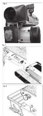
natural_image
Technical line drawings of mechanical components and parts, no visible text or symbols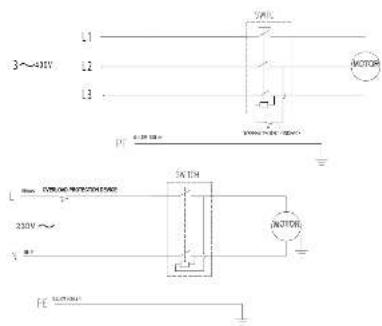

natural_image
Exploded view diagram of a mechanical assembly (no text or labels visible)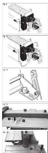
Hersteller:
Scheppach
Günzburger Straße 69
D-89335 Ichenhausen
Verehrter Kunde,
Günzburger Straße 69
D-89335 Ichenhausen
Dear customer,
we wish you a pleasant and successful working experience with your new machine.
Note:
According to the applicable product liability law the manufacturer of this device is not liable for damages which arise on or in connection with this device in case of:
- improper handling
• non-compliance with the instructions for use
• repairs by third party, non authorized skilled workers - installation and replacement of non-original spare parts
- improper use
- failures of the electrical system due to the non-compliance with the electrical specifications and the VDE 0100, DIN 57113 / VDE 0113 regulations
Recommendations:
Read the entire text of the operating instructions prior to the assembly and operation of the device.
These operating instructions are intended to make it easier for you to get familiar with your device and utilize its intended possibilities of use.
The operating instructions contain important notes how to work safely, properly and economically with your machine and how to avoid dangers, save repair costs, reduce downtime, and increase the reliability and working life of the machine.
In addition to the safety regulations contained herein, you must in any case comply with the applicable regulations of your country with respect to the operation of the machine.
Put the operating instructions in a clear plastic folder to protect them from dirt and humidity, and store them near the machine. The instructions must be read and carefully observed by each operator prior to starting the work. Only persons who have been trained in the use of the machine and have been informed on the related dangers and risks are allowed to use the machine. The required minimum age must be met.
General Notes
- When you unpack the device, check all parts for possible transport damages. In case of complaints the supplier is to be informed immediately. Complaints received at a later date will not be acknowledged.
- Check the delivery for completeness.
- Read the operating instructions to make yourself familiar with the device prior to using it.
- Use only original parts for accessories as well as for wearing and spare parts. Spare parts are available from your specialized scheppach dealer.
- Specify our part numbers as well as the type and year of construction of the device in your orders.
Slik 5.0b
| Scope of delivery | |
| Edge-grinding machine | |
| Base | |
| Adapter plate | |
| Lateral table | |
| Extraction nozzle | |
| Sanding stop plate 200 mm | |
| Lateral cutting gauge 150 mm | |
| Sanding belt, linen 80 / 120 / 240 | |
| Accessory bag | |
| Tools | |
| Operating manual | |
| Specifications | |
| Dimension LxWxH mm | 1300 / 600 / 1000 |
| Traverse table L x B mm | 790 / 220 |
| Lateral table L x B mm | 525 / 220 |
| Table height in mm | 780 |
| Adjustment of sanding support plate | 0^ - 90^ |
| Sanding belt length/ width mm | 2000 / 150 |
| Grinding support plate mm | 790 / 150 |
| Sanding belt granulation | 80 / 120 / 240 |
| Belt speed m/sec | 13 |
| ø Extraction nozzle mm | 100 |
| Weight kg | 73,0 |
| Drive | ||
| Motor V/Hz | 230–240/50 400 / 50 | |
| Input P1 kW | 2,9 2,9 | |
| Output P2 kW | 2,2 2,1 | |
| Operating mode | S6 / 40% S6 / 40% | |
| Rotational speed | 2850 2850 | |
| Undervoltage release | yes yes | |
| Plug | Schuko CEE | |
Subject to technical modifications!
Noise parameters according to EN 23746
The noise emission values determined according to EN 23746 for the sound power level or according to EN 31202 (correction factor k3 calculated according to Annex A.2 of EN 31204) for the sound level at the work place are based on the working conditions specified in ISO 7960 Annex A and are as follows:
Sound power level at the work place in dB
Idle running L_WA = 77.0 dB(A)
Processing L_WA = 87.0 dB(A)
Sound level at the work place in dB
Idle running L_pAeq = 69.0 dB(A)
Processing L_pAeq = 77.0 dB(A)
A measuring uncertainty allowance K=4 dB applies for the specified emission values.
Specifications regarding the dust emission
The dust emission values that were measured according to the “Principles for the evaluation of the dust emission (concentration parameters) of wood working machines” of the Fachausschuss Holz (Expert committee wood) are below 2 mg/m ^3 . Thus, it can be assumed that the TRK limit value for wood dust applicable in the Federal Republic of Germany is permanently and reliably fallen short of when the machine is connected to a proper operational suction.
plant with an air speed of at least 20 m/s.
Please observe the load values of the material manufacturer depending on the materials to be processed or the material quality.
In these operating instructions we have marked the places that have to do with your safety with this sign: △
General Safety Rules
When using electric tools basic safety precautions should always be followed to reduce the risk of fire, electric shock and personal injury.
- Keep guards in place and in working order.
- Remove adjusting keys and wrenches. Form the habit of checking to see that keys and adjusting wrenches are removed from the machine before turning it on.
- Keep the working area clean. Cluttered areas and benches invite accidents.
- Don't use in a dangerous environment. Don't use power tools in damp or wet locations, or expose them to rain. Keep work area well lighted.
- Keep children away. All visitors should be kept at a safe distance from the work area.
- Make your workshop kid proof. Lock your workshop. Tools not used should be kept in a dry place, inaccessible for children.
- Don't force the tool. It will do the job better and safer at the rate for which it was designed.
- Use the right tool. Don't force the tool or attachment to do a job for which is was not designed.
- Use proper extension cord. Make sure your extension cord is in good condition. When using an extension cord, be sure to use one heavy enough to carry the current your product will draw. An undersized cord will cause a drop in voltage resulting in loss of power and overheating.
- Wear proper clothing. Do not wear loose clothing, gloves, neckties, rings, bracelets, or other jewelry which may get caught in moving parts. Nonslip shoes are recommended. Wear protective hair covering to contain long hair. Roll your sleeves up to above the elbows.
- Protect your eyes by safety goggles. Everyday eyeglasses offer only little protection. They are no safety glasses. Wear a face or dust mask when working in a dusty environment.
- Secure work. Use clamps or a vice to hold work, when practical. It is safer than using your hand, and it frees both hands to operate the tool.
- Don't overreach. Keep proper footing and balance at all times.
- Maintain tools with care. Keep tools sharp and clean for best and safest performance. Follow the instructions for lubricating, and changing accessories.
- Always disconnect the machine before servicing, and when changing accessories, such as blades, bits, cutters, and the like.
- Only use recommended accessories. Consult the operating instructions for the recommended accessories. The use of improper accessories may cause risk of injury to persons.
-
Never stand on the machine. Serious injury could occur if the machine is tipped or if the cutting tool is unintentionally contacted.
-
Check for damaged parts. Before further use of the tool, a guard or other part that is damaged should be carefully checked to determine that it will operate properly and perform its intended function. Check for alignment or binding of moving parts, breakage of parts, mounting, and any other conditions that may affect its operation. A guard or other part that is damaged should be properly repaired or replaced.
- Direction of work. Push the workpiece towards the sawblade or cutter only in the moving direction of the tool.
- Never leave the machine unattended while it is running. Wait until the tool has come to an absolute standstill, before you leave the machine.
- Use the correct power connection. Do not pull the power plug to stop the machine during work. Never remove the plug from the socket by pulling the extension cord.
- Always stay attentive to what you are doing, even when using the machine regularly. Bear in mind that a fraction of a second is sufficient to cause an injury.
- Keep your safety in mind. Safety is a combination of common sense and staying alert as long as the machine is switched on.
Additional safety rules for the edge grinding machine
- WARNING: Do not use your machine until it is completely assembled and installed according to the instructions.
- If you are not familiar with the operation of the sanding machine, ask the head of the department, your teacher, or any other qualified person.
- ATTENTION: This machine has only been designed for sanding wood or similar materials. The sanding of other materials can cause fire, injuries, or damage the product.
• Always wear safety goggles.
- This machine may only be operated indoors.
- IMPORTANT: Mount and use the machine on a horizontal surface. A non-horizontal surface can damage the motor.
- If the machine tends to tilt or walk (especially when sanding long and heavy panels), it must be fastened to a solid surface of sufficient carrying force.
- Make sure the sanding belt runs in the correct direction – see arrows at the back of the belt.
- Make sure the sanding belt is running correctly so that it cannot come off the drive pulleys.
- Make sure the sanding belt is not twisted or loose.
- Firmly hold the workpiece when sanding.
- Always use the fence when using the sanding machine in horizontal position.
- Always hold the workpiece firmly to the table when using the sanding disc.
- Always hold the workpiece to the side of the sanding disc running downwards, in order to maintain the workpiece pressed to the table. By using the upward-running side of the sanding disc, the workpiece could be ejected and cause injury to persons.
- Always keep a minimum distance of about 1.5 mm or less between the table or fence and the sanding belt or disc.
- Do not wear gloves. Do not hold the workpiece with a cloth during sanding.
- Use sanding belt or disc of the correct grit corresponding with the wood.
- Never sand workpieces too small to be held safely.
- Avoid awkward hand positions where a sudden slip could cause your hand to touch the sanding belt or disc.
- When sanding a large piece of material, provide an additional support at table height.
- Never sand an unsupported workpiece. Secure the workpiece with the table or the fence. Exceptions are the sanding of curved workpieces on the outside of the sanding disc.
- Always clear the table, fence or sanding belt of scraps or other objects, before turning the machine on.
- Do not perform any layout assembly or set-up work on the table while the sanding machine is in operation.
- Switch the machine off and pull the power plug from the socket when fitting or removing accessories.
- Never leave the working area of the sanding machine while the tool is running, or as long as it has not come to an absolute standstill.

Proper Use
The machine meets the currently valid EU machine directive.
- The safety, working, and maintenance instructions and the dimensions set forth in the specifications must be observed.
- The applicable regulations for the prevention of accidents and other, generally recognized safety rules must be observed.
- The machine may only be used, maintained or repaired by trained persons who are familiar with the machine and have been informed about the dangers. Unauthorized modifications of the machine exclude a liability of the manufacturer for damages resulting from the modifications.
- The machine may only be used with original accessories and original tools of the manufacturer.
- Any other use is considered to be not intended. The manufacturer excludes any liability for resulting damages, the risk is exclusively borne by the user.

Residual Risks
The machine has been constructed according to the state of the art and the recognized safety rules. Nevertheless, single residual risks may occur during the operation.
- Risk of injuries for fingers and hands caused by the rotating grinding roller in the case of an improper guidance or support of the work piece to be ground.
- Risk of injury caused by hurling work pieces in case of an improper support or guidance.
- Danger caused by electric current if inappropriate electrical connecting lines are used.
- Furthermore, non obvious residual risks may exist in spite of all measures taken.
- Residual risks can be minimized by carefully observing the Safety Notes and the Intended Use as well as the entire operating instructions.
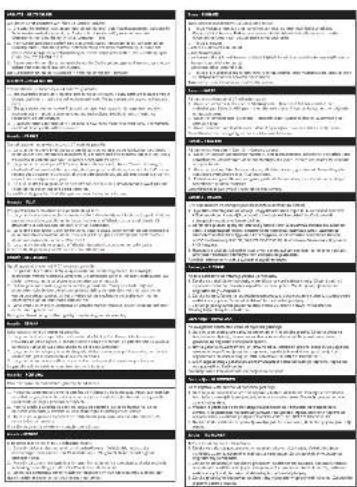
Equipment Fig. 1–2
1 Base (packed separately)
2 Sanding frame
3 Traverse table
4 Lateral table
5 Motor
6 On/Off switch
7 Extraction nozzle
8 Sanding belt
9 Sanding stop plate
10 Cross cutting gauge
11 Table clamping
12 Shifting knob
13 Belt clamping bracket
14 Adjustment handle
Assembly
For logistical reasons, your machine is not completely assembled.
We recommend attaching the machine to the base frame with which it that is delivered.
Four screws are included for this purpose.
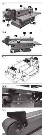
Lengthwise table with adjustable clamp, fig. 3
1 Screw the lengthwise table with the 2 locking handles loosely.
2 Place the adjustable clamp through the lengthwise adjustment plane in the housing and secure it with the 2 spring pins. Adjust the table and the scale index to 90°.
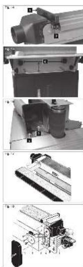
Assembling the lateral table, fig. 4
1 Mount the lateral table on the frame with 4 hex bolts, 4 washers, 4 hex nuts and tighten it slightly by hand. Align the lengthwise table into the corner and tighten.
2 Set the scale index to 90^ .
Assembling the sanding stop collar, fig. 5
Mount the sanding stop collar with 2 socket screws on the frame.
Mounting the suction hood, fig. 6
Mount the suction hood on the sanding table with a round-head screw, washer and wing nut (A).
Mounting the switch, fig. 6
Attach the switch with 2 screws to the switch plate (B).
Mounting the sanding belt, fig. 7
1 The clamping lever allows the sanding belt to be tightened or loosened.
2 To put the sanding band in place, the clamping lever must point in the direction of the arrow (1).
3 Loosen the handles, so that the pinch pin is loosened.
4 Lift up the protective shield (4) and place the sanding belt on the rollers. Pay attention to the arrows indicating the direction on the inner side of the sanding belt.
5 To tighten the sanding belt, turn the clamping lever in the direction of the arrow (2).
6 Put the protective shield back in place and tighten the handles (3).
Electrical Connection
The electric motor installed is ready to use. The terminal complies with the relevant VDE and DIN regulations. The electrical terminal on the customer's side and any extension cable used must comply with these regulations.
- The product meets the requirements EN 61000-3-11 and is subject to specific terminal conditions. This is that the use of any arbitrary connection points is not permitted.
- Under unfavorable mains conditions the device can cause temporary voltage fluctuations.
- The product is intended for the use at connection points only, that a) do not exceed the maximum permissible mains impedance “Z” (Zmax = 0.382 Ω), or b) have a continuous current-carrying capacity of at least 100 A per phase.
- You as the user need to make sure, even consulting your power company, if necessary, that your connection point at which you want to run the product, meets one of the two above mentioned requirements a) or b)
Inspect the power cords regularly for damage. During this inspection, make sure that the power cord is not connected to the mains supply.
The power cords must comply with the applicable VDE (German Association for Electrical, Electronic, and Information Technologies) and DIN (German Institute for Standardization) regulations. Use only power cords with H 07 RN designation.
A type label on the power cord is prescribed.
Faulty power cords
Power cords often suffer insulation damage.
The causes of this are:
- Pinching, when power cords are routed through windows or door cracks.
- Bending due to improper attachment or routing of the power cords.
- Cuts due to driving over the power cords.
- Insulation damages caused by yanking it out of the power outlet.
- Cracks in the insulation because of ageing.
Such faulty power cords must not be used and are, due to the damaged insulation, a danger to life!
AC motor 230 V/50 Hz
Power supply 230 volts / 50 Hz.
Power cord and extension cord must have 3 conductors = P + N + PE. - (1/N/PE).
The extension wires must have a cross-section of at least 1.5 mm^2 .
The power supply must be protected by a 16 A (or less) circuit breaker.
Three-phase motor 400 V/50 Hz
Power supply 400 volts / 50 Hz.
Power cord and extension cord must have 5 conductors = 3 P + N + PR. - (3/N/PE).
The extension wires must have a cross-section of at least 1.5 mm^2 .
The power supply must be protected by a 16 A (or less) circuit breaker.
After connecting the power supply or after relocating, check the direction of rotation. Invert polarity if necessary.
Turn the polarity inverter inside the power plug.
Start-up
Once connected to the mains supply, your Scheppach machine is operational.
Pay attention to the running direction of the grinding belt during start up; please notice the arrow sticker on the device. When connected to the grid, the rotating direction of the three-phase AC motors might be reversed. If necessary, the polarity of the wall socket should be changed. Attention: this may only be performed by a certified electrician!
Always check the sanding belt for intactness prior to each start up. This is of particular importance for used grinding belts or belts which were mounted on the machine for a longer period.
Grinding belt run, Fig. 8
Check for consistent and smooth running of the grinding belt while the machine is switched on. If required, adjust with the adjustment handle; notice the arrow indication on the handle.
Attention: Replace the defected sanding belts immediately!
To do so, please refer to the (Maintenance) chapter.
Notices on operation
Observe the safety instructions!
Start the grinding process only when the grinding belt is tensioned and the grinding machine has reached the maximum idle speed.
Do not turn off the machine as long as the work piece is in contact with the sanding belt.
Surface grinding, Fig. 9
Perform surface grinding work while the grinding belt is running horizontally.
Place work pieces with up to 78 cm length at the sanding stop plate.
For work pieces with a length over 78 cm, the sanding stop plate must be hinged down.
For a change from surface grinding to angle grinding, the height-adjustable traverse table must be in the lowest position.
Angel grinding, Fig. 10, 11, 12
For angle grinding work, the sanding belt must be set to a vertical run. The pivoting of the grinding table must only be done from the rear side of the machine.
- Turn off the machine and disconnect the mains plug.
- Lift the locking lever to release.
- To pivot the table, hold the motor console with the left hand and the sanding stop plate with the right hand. Never touch the grinding table with the right hand! There is a risk of injury such as crushing the fingers between the grinding table and the traverse table during pivoting.
- Press the locking lever down in order to adjust and lock in place.
Fig. 11
The locking lever is pre-set to zero clearance by default. By means of the adjustment screw, the locking lever may be readjusted, if required.
Angular stop, Fig. 12, 13
The angular stop (A) may be inserted in the height-adjustable traverse table or the lateral table for angle grinding.
The angular stop can be locked by using the rotary knob (B).
Tube with mechanical stop unit, Fig.14
The stop tube (1) must not topple outwards during surface grinding.
If required, retighten both safety lock nuts (2) at the joint.
Height adjustment of the traverse table, Fig. 15
After unfastening both clamping handles (C), the grinding belt can be used optimally with the height-adjustable traverse table during the grinding process.
After having performed the adjustment, fasten the clamping handles again.
Extraction for the lateral table, Fig. 16
For work on the lateral table, the extraction nozzle (D) is removed from the traverse grinding and attached to the traverse table by means of a clamping screw (E).
Maintenance
Prior to each maintenance and cleaning, the motor must be turned off and the mains plug disconnected.
All protective and safety equipments must be mounted again immediately after repair and maintenance work have been completed.
Grinding belt replacement, Fig. 17
1 Fold out the sanding stop plate.
2 Open the protective screen.
3 Unfasten the wing nut on the extraction nozzle and pull the latter one backwards.
4 Release the old grinding belt and remove it.
5 While placing the new grinding belt, observe the arrows for running direction on the inside of the grinding belt.
6 Tighten the grinding belt.
7 Attach the extraction nozzle to the grinding belt again and fasten the wing nut.
8 Adjust the belt run while the machine is running.
Belt replacement, Fig. 18
1 Remove the belt protection (1)
2 Unscrew the bearing flap (2)
3 Unfasten the 4 motor attachment screws (3)
4 Release the clamping nuts (4): the belt is un-tightened
5 Replace the belt
6 Fasten the clamping nut (4): the strip is tightened
7 Tighten the 4 motor attachment screws
8 Fasten the bearing flap (2) and the belt protection (1)
Further maintenance notices
- Always keep the table surfaces free of resin. Do not use aggressive cleaning detergents!
-
Remove larger grinding dust accumulations in the machine.
-
Grinding belts must be rolled in towards the bearing, DO NOT BEND!
- Grinding belts must not be suspended on nails since this may lead to damages such as kinks or cracks.
- At the end of the working day and during longer breaks, un-tighten the grinding belt on the machine.
Trouble shooting
| Problem Possible Cause Solution | ||
| Motor does not start up. – no electricity | – capacitor and/or switch defective– extension cord defective | – check fuses– allow an expert to check capacitor and switch– unplug the machine, check and replace, if necessary, the extension cord if necessary |
| Sanding belt slides through – sanding | belt stretched after long use– pinch pin is not correctly installed– too much pressure downwards | – put on a new sanding belt– turn the pinch pin exactly– move the work piece while it is being sanded |
| Sanding belt does not run evenly – sanding | belt is defective or torn– sanding belt is stretched after long use | – check, replace– replace the sanding belt with a new one |
| Sanding belt runs in the wrong direction | – wrong direction in the rotary motor | let an electrician check the polarity of the wall socketWarning: remove mains fuse! |
| Warning symbols | ||
| Wear proper work shoes and gloves! |  |  |
| Wear safety goggles! |  | |
| Read manual! |  | |
Constructeur:
scheppach
Tuotannossa LWA = 87,0 dB(A)
Tuotannossa LpAeq = 77,0 dB(A)
Günzburger Straße 69
D-89335 Ichenhausen
Gentile cliente,
Günzburger Straße 69
D-89335 Ichenhausen
Krere kunde,
Tomgang L_pAeq = 69,0 dB(A)
Bearbejdning L_pAeq = 77.0 dB(A)
Günzburger Straße 69
D-89335 Ichenhausen
Arade kund!
Vinkelslipning, figur 10, 11, 12
Günzburger Straße 69
D-89335 Ichenhausen
Kjrere kunde,
Støy under arbeide--dB(A) 89,0 89,0
Støynormer
Flatesliping, Fig. 9
Vinkelsliping, Fig. 10, 11, 12
Noise: measured L_WA = dB(A) ; guaranteed L_VIA = dB(A) P = KW; L/∅ = cm Notified Body: Notified Body No.:
2004/26/EC
Emission. No:
Standard references: EN 60204-1; EN 61029-1; EN 55014-1; EN 55014-2; EN 61000-3-2; EN 61000-3-11
Subject to change without notice
Documents registar: Andreas Pecher
Günzburger Str. 69, D-89335 Ichenhausen