
SeeSnake microREEL CA350 - Inspection camera RIDGID - Free user manual and instructions
Find the device manual for free SeeSnake microREEL CA350 RIDGID in PDF.

| Product Type | Handheld digital inspection camera |
| Brand | RIDGID |
| Model | SeeSnake microREEL CA350 |
| Camera head diameter | 17 mm (3/4 in) |
| Standard cable length | 0.90 m (3 ft) |
| Maximum length with extensions | 9 m (30 ft) |
| Head and cable waterproofing | Up to 3 m (10 ft), IP67 rating |
| Display | 3.5-inch (90 mm) color TFT screen, 320 x 240 resolution |
| Lighting | 4 adjustable white LEDs |
| Photo resolution | 640 x 480 pixels (JPEG) |
| Video resolution | 640 x 480 pixels (MP4), up to 30 fps |
| Internal memory | 235 MB |
| External memory | SD card up to 32 GB (8 GB included) |
| Video output | Composite (PAL/NTSC selectable) |
| Power supply | Rechargeable 12 V Li-ion battery or 12 V/3 A power adapter |
| Weight | 2.5 kg (5.5 lb) |
| Included accessories | Hook, magnet, mirror, headset with microphone, USB cable, RCA cable, 8 GB SD card, charger, power adapter |
| Operating temperature | 0 °C to 45 °C (32 °F to 113 °F) |
| Storage temperature | -20 °C to 60 °C (-4 °F to 140 °F) |
| Maintenance and cleaning | Clean the head and cable after each use with a mild detergent. Clean the screen with a soft cloth. Clean the connections with alcohol. |
| Repairability | Repairs must be performed by a RIDGID authorized service center. Only use original replacement parts. |
| Warranty | Full Lifetime Warranty |
Frequently Asked Questions - SeeSnake microREEL CA350 RIDGID
User questions about SeeSnake microREEL CA350 RIDGID
0 question about this device. Answer the ones you know or ask your own.
Ask a new question about this device
Download the instructions for your Inspection camera in PDF format for free! Find your manual SeeSnake microREEL CA350 - RIDGID and take your electronic device back in hand. On this page are published all the documents necessary for the use of your device. SeeSnake microREEL CA350 by RIDGID.
USER MANUAL SeeSnake microREEL CA350 RIDGID
natural_image
RiDGD 12V endoscope device with red and black casing, connected by black cables (no visible text or symbols on device body)


RIDGID.com/qr/ca350
EN P. 1
FR P. 17
ES P. 35
DE P. 53
NL P. 71
IT P. 89
PT P. 107
SV P. 125
DA P. 143
NO P. 159
FI P. 175
PL P. 193
CZ P. 211
SK P. 229
RO P. 247
HU P. 265
EL P. 283
HR P. 303
SL P. 321
SR P. 339
RU P. 357
TR P. 377
KK P. 393
Table of Contents
Safety Symbols 2
General Safety Information
Work Area Safety 2
Electrical Safety 2
Personal Safety....2
Equipment Use and Care 2
Battery Use and Care 2
Service....3
Specific Safety Information
micro CA-350 Inspection Camera Safety....3
Description, Specifications and Standard Equipment
Description....4
Specifications....4
Standard Equipment 5
Controls 5
FCC Statement......5
Electromagnetic Compatibility (EMC) 6
Icons 6
Tool Assembly
Changing/Installing Batteries 7
Powering with the AC Adapter....7
Installing Imager Head Cable or Extension Cables....7
Installing Accessories 7
Installing SD™ Card 8
Pre-Operation Inspection....8
Tool and Work Area Set-Up....8
Operating Instructions....9
Live Screen....10
Image Adjustment....10
Image Capture 11
Menu....11
Time Stamp 12
Language....12
Date/Time 12
TV-Out 12
Update Firmware 12
Speaker 12
Auto Power Off 12
Factory Reset....12
About 12
Transferring Images to a Computer 12
Connecting to TV 13
Using with SeeSnake® Inspection Equipment....13
Maintenance
Reset Function.... 14
Optional Equipment 14
Storage 14
Service and Repair 14
Disposal....15
Troubleshooting....16
Declaration of Conformity....Inside Back Cover
Lifetime Warranty....Back Cover
*Original Instructions - English
micro CA-350 Inspection Camera
natural_image
RiDgID endoscope device with visible I/O ports and cable, no text or symbols on the device itself.
WARNING!
Read this Operator's Manual carefully before using this tool. Failure to understand and follow the contents of this manual may result in electrical shock, fire and/or serious personal injury.
| micro CA-350 Inspection Camera | |
| Record Serial Number below and retain product serial number which is located on nameplate. | |
| Serial No. | |
Safety Symbols
In this operator's manual and on the product, safety symbols and signal words are used to communicate important safety information. This section is provided to improve understanding of these signal words and symbols.

This is the safety alert symbol. It is used to alert you to potential personal injury hazards. Obey all safety messages that follow this symbol to avoid possible injury or death.

DANGER
DANGER indicates a hazardous situation which, if not avoided, will result in death or serious injury.

WARNING
WARNING indicates a hazardous situation which, if not avoided, could result in death or serious injury.

CAUTION
CAUTION indicates a hazardous situation which, if not avoided, could result in minor or moderate injury.

NOTICE NOTICE indicates information that relates to the protection of property.

This symbol means read the operator's manual carefully before using the equipment. The operator's manual contains important information on the safe and proper operation of the equipment.

This symbol means always wear safety glasses with side shields or goggles when handling or using this equipment to reduce the risk of eye injury.

This symbol indicates the risk of hands, fingers or other body parts being caught or wrapped in gears or other moving parts.

This symbol indicates the risk of electrical shock.
General Safety Information

WARNING
Read all safety warnings and instructions. Failure to follow the warnings and instructions may result in electric shock, fire and/or serious injury.
SAVE THESE INSTRUCTIONS!
Work Area Safety
- Keep your work area clean and well lit. Cluttered or dark areas invite accidents.
- Do not operate equipment in explosive atmospheres, such as in the presence of flammable liquids, gases or dust. Equipment can create sparks which may ignite the dust or fumes.
- Keep children and by-standers a way while operating equipment. Distractions can cause you to lose control.
Electrical Safety
- Avoid body contact with earthed or ground surfaces such as pipes, radiators, ranges and refrigerators. There is an increased risk of electrical shock if your body is earthed or grounded.
- Do not expose equipment to rain or wet conditions. Water en tering equipment will increase the risk of electrical shock.
Personal Safety
- Stay alert, watch what you are doing and use common sense when operating equipment. Do not use equipment while you are tired or under the influence of drugs, alcohol or medication. A moment of inattention while operating equipment may result in serious personal injury.
- Do not overreach. Keep proper footing and balance at all times. This enables better control of the power tool in unexpected situations.
- Use personal protective equipment. Always wear eye protection. Protective equipment such as dust mask, non-skid safety shoes, hard hat or hearing protection used for appropriate conditions will reduce personal injuries.
Equipment Use and Care
- Do not force equipment. Use the correct equipment for your application. The correct equipment will do the job better and safer at the rate for which it is designed.
- Do not use equipment if the switch does not turn it ON and OFF. Any tool that cannot be controlled with the switch is dangerous and must be repaired.
- Disconnectthebatteriesfromtheequipment before making any adjustments, changing accessories, or storing. Such preventive safety measures reduce the risk of injury.
- Store idle equipment out of the reach of children and do not allow persons unfamiliar with the equipment or these instructions to operate the equipment. Equipment can be dangerous in the hands of untrained users.
- Maintain equipment. Check for missing parts, breakage of parts and any other condition that may affect the equipment's operation. If damaged, have the equipment repaired before use. Many accidents are caused by poorly maintained equipment.
- Use the equipment and accessories in accordance with these instructions, taking into account the working conditions and the work to be performed. Use of the equipment for operations different from those intended could result in a hazardous situation.
- Use only accessories that are recommended by the manufacturer for your equipment. Accessories that may be suitable for one piece of equipment may become hazardous when used with other equipment.
- Keep handles dry and clean; free from oil and grease. Allows for better control of the equipment.
Battery Use & Care
- Recharge only with the charger specified by the manufacturer. A charger that is suitable for one type of battery pack may create a risk of fire when used with another battery pack.
- Use equipment only with specifically designated battery packs. Use of any other battery packs may create a risk of injury and fire.
- When a battery pack is not in use, keep it away from other metal objects, like paper clips, coins, keys, nails, screws or other small metal objects that can make a connection from one terminal
to another. Shorting the battery terminals together may cause burns or a fire.
- Under abusive conditions, liquid may be ejected from the battery; avoid contact. If contact accidentally occurs, flush with water. If liquid contacts eyes, additionally seek medical help. Liquid ejected from the battery may cause irritation or burns.
Service
- Have your equipment serviced by a qual i fied repair person using on ly identical replacement parts. This will ensure that the safety of the tool is maintained.
Specific Safety Information
WARNING
This section contains important safety information that is specific to the inspection camera.
Read these precautions carefully before using the RIDGID ® micro CA-350 In spec-tion Cam era to reduce the risk of elec-trical shock or other serious injury.
SAVE THESE INSTRUCTIONS!
A manual holder is supplied in the carrying case of the micro CA-350 Inspection Camera to keep this manual with the tool for use by the operator.
micro CA-350 Inspection Camera Safety
- Do not expose the display unit to water or rain. This increases the risk of electrical shock. The micro CA-350 imager head and ca ble are waterproof to 10' (3 m). The hand-held display unit is not.
- Do not place the micro CA-350 Inspection Cam era anywhere that may contain a live electrical charge. This increases the risk of electrical shock.
- Do not place the micro CA-350 Inspection Cam era anywhere that may contain moving parts. This increases the risk of entanglement injuries.
- Do not use this device for personal inspection or medical use in any way. This is not a medical device. This could cause personal injury.
• Always use appropriate personal pro-
tective equipment while handling and using the micro CA-350 Inspection Camera. Drains and other areas may contain chemicals, bacteria and other substances that may be toxic, infectious, cause burns or other issues. Appropriate personal protective equipment always includes safe ty glasses and gloves and may include equipment such as latex or rubber gloves, face shields, goggles, protective clothing, respirators and steel-toedfootwear.
- Practice good hygiene. Use hot, soapy water to wash hands and other body parts exposed to drain contents after handling or using the micro CA-350 In spec tion Camera to inspect drains and other areas that may contain chemicals or bacteria. Do not eat or smoke while operating or handling the micro CA-350 Inspection Camera. This will help prevent contamination with toxic or infectious material.
- Do not operate the micro CA-350 In spection Camera if operator or device is standing in water. Operating an electrical device while in water increases the risk of electrical shock.
-
Before operating a micro CA-350 In spec-tion Camera, read and understand:
-
This operator's manual,
– The battery/charger manual, - The instructions for any other equipment used with this tool,
Failure to follow all instructions and warnings may result in property damage and/or serious injury.
If you have any question concerning this RIDGID® product:
- Contact your local RIDGID distributor.
- Visit RIDGID.com to find your local RIDGID contact point.
- Contact Ridge Tool Technical Service DepartmentatProToolsTechService@Emerson.com, or in the U.S. and Canada call 844-789-8665.
Description, Specifications and Standard Equipment
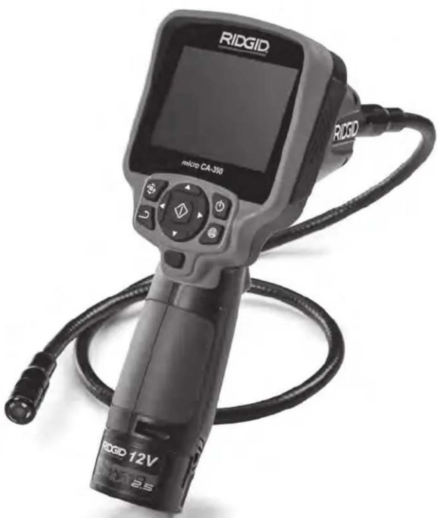
Description
The RIDGID ® micro CA-350 Inspection Camera is a powerful handheld digital recording device. It is a complete digital platform that allows you to perform inspections and record pictures and videos in hard to reach areas. Several image manipulation features such as image rotation and digital zoom are built into the system to ensure detailed and accurate visual inspections. The tool has external memory and TV-Out features. Accessories (hook, magnet and mirror) are included to attach to the imager head to provide application flexibility.
Specifications
Recommended Use....Indoor
Viewable Distance.....0.4" (10 mm) to ∞
Display.... 3.5" (90 mm) Color TFT (320 x 240 Resolution)
Camera Head...... 3/4" (17mm)
Lighting....4 Adjustable LEDs
Cable Reach....3' (0,9 m), Expandable to 30' (9 m) with OptionalExtensions, Imager and Cable are Water proof to 10' (3 m), IP67
Photo Format......JPEG
Image Resolution ..... 640 x 480
Video Format......MP4
Video Resolution ...... 640 x 480
Frame Rate.....up to 30 FPS
TV-Out ....PAL/NTSC User selectable
Built-In Memory ...... 235 MB Memory
External Memory...... SD™ Card 32 GB max (8 GB supplied)
Data Output...... USB Data Cable and SD™ Card
Operating
Temperature.... 32 to 113°F (0 to 45°C)
Storage Temperature. -4°F to 140°F (-20°C to 60°C)
Power Supply ......12V Li-Ion Battery
AC Adapter 12V,
3 Amp
Weight....5.5 lbs (2,5 kg)
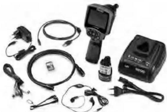
Standard Equipment
The micro CA-350 Inspection Camera comes with the following items:
- micro CA-350 Handset
- 17 mm Imager
• 3' (90 cm) USB Cable
• 3' (90 cm) RCA Cable with Audio - Hook, Magnet, Mirror Attachments
• 12 V Li-Ion Battery
• Li-Ion Battery Charger with Cord - AC Adapter
• Headset Accessory with Microphone - 8 GB SD™ Card
- Operator's Manual Pack
natural_image
Assorted electronic devices including a handheld device, earplifier, and charging case (no visible text or labels)Figure 1 – micro CA-350 Inspection Camera
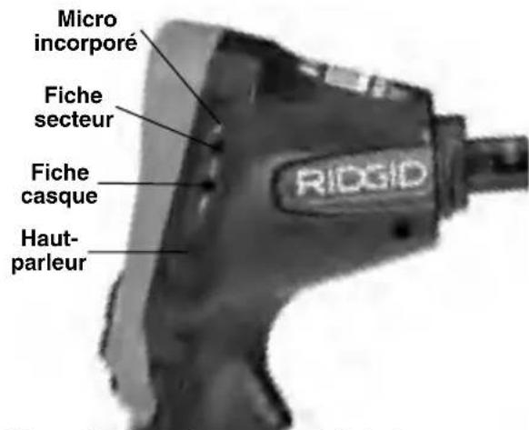
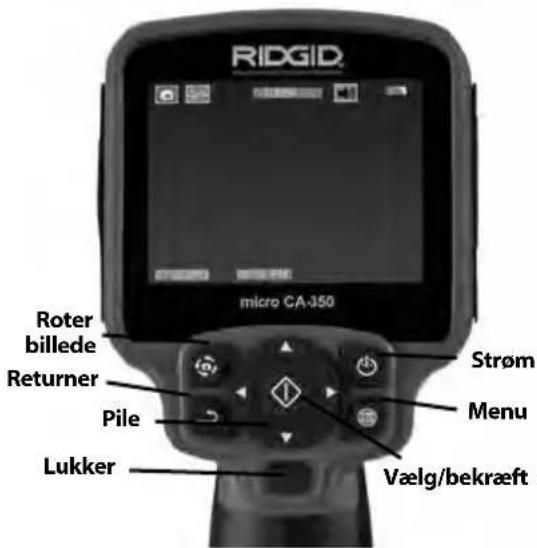
Controls
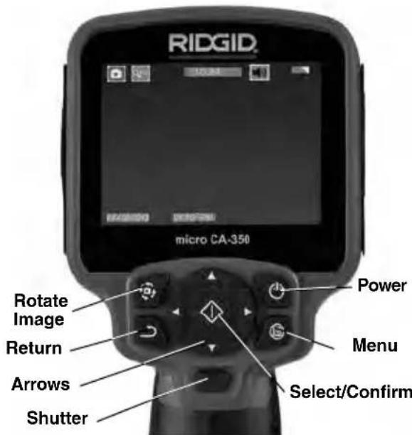
Figure 2 – Controls
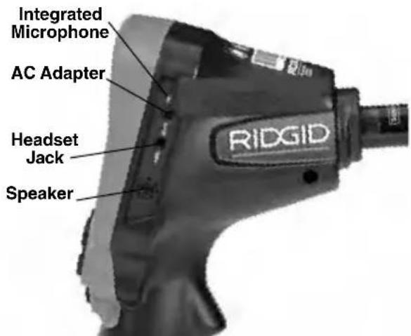
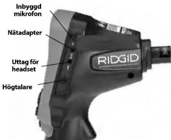
Figure 3 – Right Side Port Cover
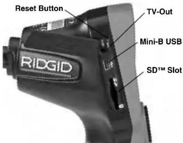
Figure 4 – Left Side Port Cover
FCC Statement
This equipment has been tested and found to comply with the limits for a Class B digital device, pursuant to part 15 of the FCC Rules. These limits are designed to provide reasonable protection against harmful interference in a residential installation.
This equipment generates, uses, and can radiate radio frequency energy and, if not installed and used in accordance with the instructions, may cause harmful interference to radio communications.
However, there is no guarantee that interference will not occur in a particular installation.
If this equipment does cause harmful interference to radio or television reception, which can be determined by turning the equipment OFF and ON, the user is encouraged to try to correct the interference by one or more of the following measures:
- Reorient or relocate the receiving antenna.
- Increase the separation between the equipment and receiver.
- Consult the dealer or an experienced radio/TV technician for help.
Electromagnetic Compatibility (EMC)
The term electromagnetic compatibility is taken to mean the capability of the product to function smoothly in an environment where electromagnetic radiation and electrostatic discharges are present and without causing electromagnet interference to other equipment.
NOTICE The RIDGID micro CA-350 Inspection Camera conforms to all applicable EMC standards. However, the possibility of it causing interference in other devices cannot be precluded.
Icons
 | Battery Life Indicator – Fully charged battery. |
 | Battery Life Indicator – Less than 25% of battery charge remains. |
 | SDTM Card – Indicates an SD card has been inserted into the device. |
 | Still Camera – Indicates device is operating in still camera mode. |
 | Video Camera – Indicates device is operating in video camera mode. |
 | Playback Mode – Selecting this icon allows you to view and delete previous ly saved images and video. |
 | Menu – Push select on this icon to be taken to the menu screen. |
 | Select – Pressing select from the live screen will take you to the playback screen. |
 | Return – Pressing return from the live screen will switch between camera and video. Return will also back out of menu and playback mode. |
 | LED Brightness – Press right & left arrows to change the LED brightness. |
 | Zoom – Press up & down arrows to change the zoom from 1.0x to 2.0x. |
 | Save – Indicates image or video has been saved to memory. |
 | Trash – Delete confirmation icon. |
 | Mode – Select between image, video or playback. |
 | Time Stamp – Select to display or hide date and time on live screen. |
 | Language – Choose between, English, French, Spanish, German, Dutch, Italian, etc. |
 | Time and Date – Enter this screen to set time and date. |
 | TV – Chose between NTSC and PAL to enable TV out video format. |
 | Update Firmware – Use to update unit with most current software. |
 | Speaker/Microphone – Turns speaker and microphone ON or OFF during recording and playback. |
 | Automatic Power Off – Device will automatically shut down after 5, 15 or 60 minutes of inactivity. |
 | Factory Reset – Restore factory defaults. |
 | About – Displays software version. |
Tool Assembly
WARNING
To reduce the risk of serious injury during use, follow these procedures for proper assembly.
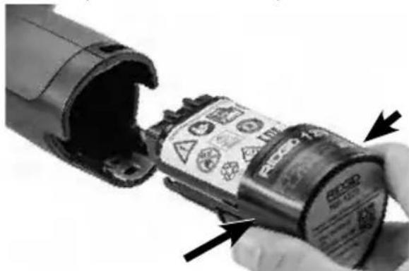
Changing/Installing Batteries
The micro CA-350 is supplied without the battery installed. If the battery indicator displays □, the battery needs to be recharged. Remove the battery prior to storage.
- Squeeze the battery tabs (See Figure 5) and pull to remove battery.
natural_image
Close-up of a hand holding a cylindrical device with warning labels and arrows indicating assembly or inspection (no readable text or symbols)Figure 5 – Removing/Installing Battery
- Insert contact end of battery into the inspection tool, as shown in Figure 5.
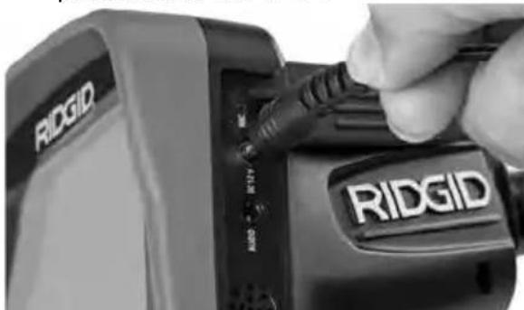
Powering with the AC Adapter
The micro CA-350 Inspection Camera can al so be powered using the supplied AC Adapter.
- Open the right side port cover (Figure 3).
- With dry hands, plug the AC adapter into the outlet.
- Insert the AC adapter barrel plug into the port marked "DC 12V".
natural_image
Close-up of a hand inserting a USB into an R1DGID device (no visible text or symbols on the device body)Figure 6 – Powering the Unit with AC Adapter
Installing the Imager Head Cable or Extension Cables
To use the micro CA-350 Inspection Cam er a, the imager head cable must be connected to the handheld display unit. To connect the cable to the handheld display unit, make sure the camera socket key and display unit socket slot (Figure 7) are properly aligned. Once they are aligned, finger tighten the knurled knob to hold the connection in place.

natural_image
Close-up of two black industrial pipe fittings with no visible text or symbolsFigure 7 – Cable Connections
3' (90 cm) and 6' (180 cm) cable extensions are available to increase the length of your camera cable up to 30 feet (9 m). To install an extension, first remove the camera head cable from the display unit by loosening the knurled knob. Connect the extension to the handheld as described above (Figure 7). Connect the keyed end of the camera head cable to the slotted end of the extension and finger tighten the knurled knob to hold the connection in place.
Installing Accessories
The three included accessories, (Hook, Magnet, Mirror) all attach to the imager head the same way.
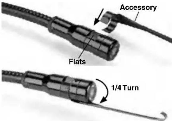
Figure 8 – Installing an Accessory
To connect, hold the imager head as shown in Figure 8. Slip the semicircle end of the accessory over the flats of the imager head. Then rotate the accessory a 1/4 turn to retain.
Installing SD™ Card
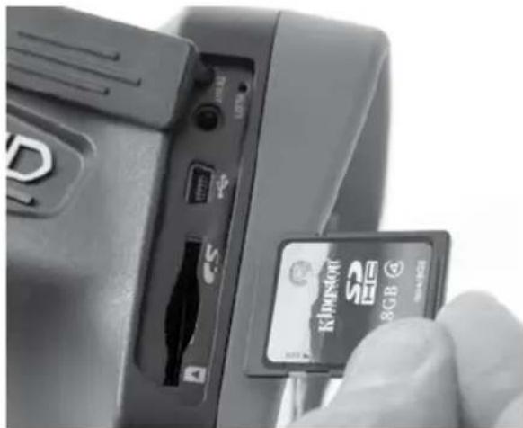
Open the left side port cover (Figure 4) to access the SD card slot. Insert the SD card into the slot with the angled corner up, matching the icon next to the slot (Figure 9). SD cards can only be installed one way – do not force. When an SD card is installed, a small SD card icon will appear in the upper left hand portion of the screen, along with the number of images or length of video that can be stored on the SD card.
natural_image
Close-up of a hand inserting a 3GB memory card into a device (no visible text or symbols on the card or background)Figure 9 – Inserting the SD Card
Pre-Operation Inspection
WARNING
Before each use, inspect your Inspection Camera and correct any problems to reduce the risk of serious injury from electric shock and other causes and prevent tool damage.
- Make sure the unit is OFF.
- Remove the battery and inspect it for signs of dam age. Re place battery if necessary. Do not use Inspection Camera if the battery is damaged.
-
Clean any oil, grease or dirt from the equipment. This aids inspection and helps prevent the tool from slipping from your grip.
-
Inspect micro CA-350 Inspection Camera for any broken, worn, missing or binding parts or any condition which may prevent safe and normal operation.
-
Inspect the camera head lens for condensation. To avoid damaging the unit, do not use the camera if condensation forms inside the lens. Let the water evaporate before using.
-
Inspect the full length of the cable for cracks or damage. A damaged cable could allow water to enter the unit and increase the risk of electrical shock.
-
Check to make sure the connections between the handheld unit, extension cables and imager cable are tight. All connections must be properly assembled for the cable to be water resistant. Con firm unit is properly assembled.
-
Check that the warning label is present, firmly attached and readable (Figure 10).

Figure 10 – Warning Label
-
If any issues are found during the inspection, do not use the inspection camera until it has been properly serviced.
-
With dry hands, re-install the battery.
-
Press and hold the Power Button for one second. The imager lights should come on, then a splash screen will appear. Once the camera is ready, a live image of what the camera sees is displayed on the screen. Consult the Troubleshooting section of this manual if no picture appears.
-
Press and hold the Power Button for one second to turn camera OFF.
Tool and Work Area Set-Up
WARNING


Set up the micro CA-350 Inspection Camera and work area according to these procedures to reduce the risk of injury from electrical shock, entanglement and other causes and prevent tool damage.
1. Check work area for:
- Adequate lighting
- Flammable liquids, vapors or dust that may ignite. If present, do not work in area until sources have been identified and corrected. The micro CA-350 In spection Camera is not explosion proof and can cause sparks.
-
Clear, level, stable, dry place for operator. Do not use the inspection camera while standing in water.
-
Examine the area or space that you will be inspecting and determine if the micro CA-350 Inspection Camera is the correct piece of equipment for the job.
- Determine the access points to the space. The minimum opening the camera head can fit through is approximately 34'' (19 mm) in diameter for the 17 mm camera head.
- Determine the distance to the area to be inspected. Extensions can be added to the camera to reach up to 30' (9 m).
- Determine if there are any obstacles that would require very tight turns in the cable. The inspection camera ca ble can go down to a 5" (127 mm) radius without damage.
- Determine if there is any electrical power supplied to the area to be inspected. If so, the power to the area must be turned OFF to reduce the risk of electric shock. Use appropriate lock out procedures to prevent the power from being turned back on during the inspection.
- Determine if any liquids will be encountered during the inspection. The cable and imager head are waterproof to a depth of 10' (3 m). Greater depths may cause leakage into the cable and imager and cause electric shock or damage the equipment. The handheld display unit is water resistant (IP54) but should not be submerged in water.
- Determine if any chemicals are present, especially in the case of drains. It is important to understand the specific safety measures required to work a round any chemicals present. Contact the chemical manufacturer for required information. Chemicals may damage or degrade the inspection camera.
- Determine the temperature of the area and items in the area. See Specifica-
tions. Use in areas outside of specification temperatures or contact with hotter or colder items could cause camera damage.
- Determine if any moving parts are present in the area to be inspected. If so, these parts must be deactivated to prevent movement during inspection to reduce the risk of entanglement. Use appropriate lock out procedures to prevent the parts from moving during the inspection.
If the micro CA-350 Inspection Camera is not the correct piece of equipment for the job, other inspection equipment is available from RIDGID. For a complete listing of RIDGID products, see the RIDGID catalog, online at RIDGID.com.
- Make sure the micro CA-350 Inspection Camera has been properly inspected before each use.
- Install the correct accessories for the application.
Operating Instructions
WARNING


Always wear eye protection to protect your eyes against dirt and other foreign objects.
Follow operating instructions to reduce the risk of injury from electrical shock, entanglement and other causes.
- Make sure that the Inspection Camera and work area have been properly set up and that the work area is free of bystanders and other distractions.
- Press and hold the Power Button for two seconds. The imager lights should come ON, then a splash screen will appear. This screen tells you the device is booting up. Once the product is fully powered up, the screen will automatically switch to the live screen.

Figure 11 – Splash Screen (Note: Version will change with each firmware update.)
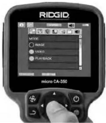
Figure 13 – Screen Shot of Mode Selection
Live Screen
The live screen is where you will do most of your work. A live image of what the camera sees is displayed on the screen. You can zoom, adjust LED brightness and take images or video from this screen.
The screen has a status bar at the top showing the tool mode, zoom, SD™ card icon if inserted, available memory and speaker/mic ON/OFF. The bottom bar shows information about date and time if time stamp is ON.
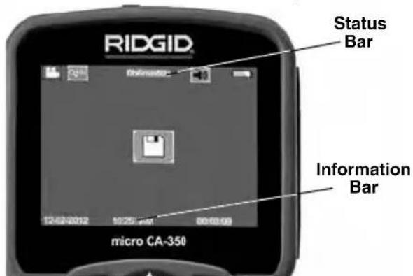
Figure 12 – Live Screen
When the Inspection Camera is turned ON, the default mode is for capturing still images. Pressing the menu button at any time will access the menu. The menu will overlay on the LIVE Screen. Use the right and left arrow buttons to switch to the MODE category. Use the up and down arrows▼ to navigate between menu items and press select ▶ as desired.
-
If the other inspection camera settings (Time Stamp, Language, Date/Time, TV Out, Update Firmware, Speaker/Microphone, Auto Power OFF, Factory Reset) need to be adjusted, see Menu Section.
-
Prepare the camera for inspection. The camera cable may need to be pre-formed or bent to properly inspect the area. Do not try to form bends less than 5" (13cm) radius. This can damage cable. If inspecting a dark space, turn the LEDs on before inserting the camera or cable.
Do not use excessive force to insert or withdraw the cable. This may result in damage to the inspection camera or inspection area. Do not use the cable or imager head to modify surroundings, clear pathways or clogged areas, or as anything other than an inspection device. This may result in damage to the Inspection camera or inspection area.
Image Adjustment
Adjust LED Brightness : Pressing the right and left arrow button▶◀ on the button pad (In live screen) will increase or decrease the LED brightness. A brightness indicator bar will be displayed on the screen as you adjust brightness.

Figure 14 – Adjusting LED
Zoom : The micro CA-350 Inspection Camer a has a 2.0x digital zoom. Simply press the up and down arrows ▲▼ while in the live screen to zoom in or out. A zoom indicator bar will be displayed on the screen as you adjust your zoom.

Figure 15 – Adjusting Zoom
Image Rotation : If needed, the image/video seen on the screen can be rotated in 90 degree increments counter clockwise by pressing the rotate image button.
Image Capture
Capturing a Still Image
While in the live screen, make sure the still camera icon is present at the top left portion of the screen. Press the shutter button to capture the image. The save icon will momentarily appear on the screen. This indicates the still image has been saved to the internal memory or SD™ card.
Capturing a Video
While in the live screen, make sure the video camera icon is present at the top left portion of the screen. Press the shutter button to start capturing video. When the device is recording a video, a red outline will flash around the video mode icon and the recording duration will show at the top of the screen. Press the shutter button again to stop the video. It may take several seconds to save the video if saving to the internal memory.
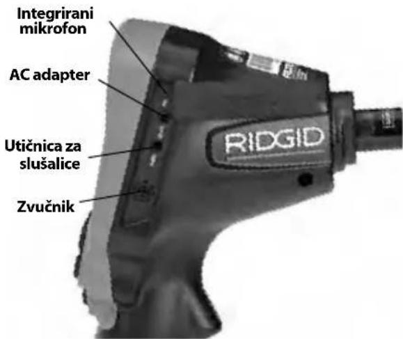
The micro CA-350 features an integrated microphone and speaker for recording and playback of audio with video. A headset with integrated microphone is included and may be used instead of the integrated speaker and microphone. Plug the headset into the audio port on the right side of the camera.
- When the inspection is complete, carefully withdraw the camera and cable from the inspection area.
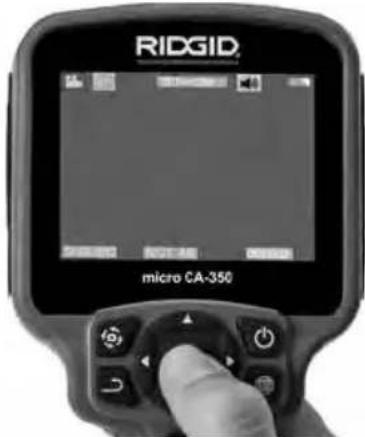
Figure 16 – Video Recording Screen
Menu
Pressing the Menu button ☐ at any time will access the menu. The menu will overlay on the LIVE Screen. From the menu, the user will be able to change to the various modes or enter the settings menu.
There are different setting categories to choose from (Figure 17) while in the settings screen. Use the right and left arrow buttons ▶◀ to switch from one category to the next. Use the up and down arrows▲▼ to navigate the menu items. The selected category will be highlighted with a bright red outline. Once the desired setting is reached, press select to change to the new selection. The changes are automatically saved when they are changed.
While in menu mode, you can press the Return button → to return to the previous screen or to the live screen.
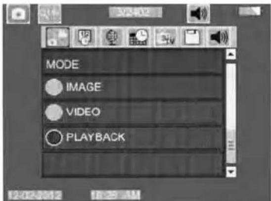
Figure 17 – Settings Screen
Playback Mode
-
Pressing the Select button in the live screen will enter playback mode. Select either Image or Video to playback the desired file. The playback mode is the interface into saved files. It will default to the last file recorded.
-
While reviewing the image the user will be able to cycle through all saved images, delete an image and display file information.
-
While reviewing a video, a user will be able to navigate through videos, pause, restart and delete. A user will only be able to playback images and video from internal memory when SD™ Card is not inserted.
Deleting Files
Press Menu button ☐ while in playback mode to delete the image or video. The delete confirmation dialog allows the user to delete unwanted files. The active icon is outlined in red. Navigation is done with the arrow buttons ✦.
Time Stamp
Enable or Disable the display of the Date and Time.
Language

Select the "Language" icon in the menu and press Select. Select different languages with up/down arrow buttons▲▼, then press Select to save the language setting.
Date/Time

Select Set Date or Set Time to set the current date or time. Select Format Date or Time to change how the date/time is displayed.
TV-Out
Select the "NTSC" or "PAL" to enable the TV-Out for the video format required. Screen will go black and image will be transmitted to external screen. To get live image on unit, hit Power button ⏻ to disable function.
Update Firmware

Select Update Firmware to install the latest version of software on the unit. Software will have to be loaded onto a SD™ Card and inserted in to the unit. Updates can be found at RIDGID.com.
Speaker

Select the Speaker icon in the menu and press Select ☐. Select ON or OFF with up/down button ▲▼ to keep the speaker ON or OFF during video playback.
Auto Power Off

Select the Auto Power Off icon and press select ⓘ . Select disable to turn OFF the auto ma tic shut down function. Select the 5 Minutes, 15 Minutes or 60 Minutes to turn OFF the tool upon 5/15/60 minutes of non-operation. Auto matic shut down setting will not be activated when recording or playing video.
Factory Reset

Select the Reset icon and press Select ⏻. Confirm the reset function by selecting Yes and press Select ⏻ again. This will reset the tool to the factory set up.
About ?
Select the About function to display the firmware revision of the micro CA-350 as well as the software copyright information.
Transferring Images to a Computer
With the unit powered ON, connect the micro CA-350 to a computer using the USB cable. The USB connected screen is displayed on the micro CA-350. The internal memory and SD™ card (if applicable) will appear as separate drives on the computer and are now accessible as a standard USB storage device. The copy and delete options are available from computer operation.
Connecting to TV
The micro CA-350 Inspection Camera can be connected to a television or other monitor for remote viewing or recording through the included RCA cable.
Open the right side port cover (Figure 3). Insert the RCA cable into the TV-Out jack. Insert the other end of the cable into the Video-In jack on the television or monitor. Check to make sure the video format (NTSC or PAL) output is set properly. The television or monitor may need to be set to the proper input to allow viewing. Select the appropriate TV-Out format using the menu.
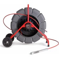
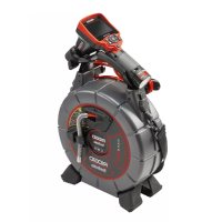
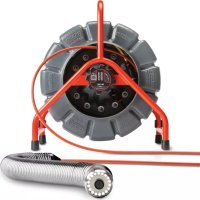
Use with SeeSnake® Inspection Equipment
The micro CA-350 Inspection Camera can also be used with various SeeSnake Inspection Equipment and is specifically designed to be used with the microReel, microDrain™ and the nanoReel Inspection Systems. When used with these types of equipment, it retains all of the functionality described in this manual. The micro CA-350 Inspection Camera can also be used with other SeeSnake Inspection Equipment for viewing and recording only.
For use with SeeSnake Inspection Equipment, the imager head and any cable extensions must be removed. For the microReel, microDrain™, nanoReel and similar equipment, see the operator's manual for information on proper connection and use. For other SeeSnake Inspection Equipment (typically a reel and monitor), an adapter must be used to connect the micro CA-350 Inspection Camer a to a Video-Out port on the SeeSnake Inspection Equipment. When connected in this manner, the micro CA-350 Inspection Camera will display the camera view and can be used for recording.
When connecting to SeeSnake Inspection Equipment (microReel, microDrain™, or nano Reel), align the interconnect module connected to your reel with the cable connector on the micro CA-350 Inspection Camera, and slide it straight in, seating it squarely. (See Figure 18)

natural_image
Close-up of a black R1DGID power tool with attached probe (no visible text or symbols on the tool itself)Figure 18 – Camera Connector Plug Installed
NOTICE Do not twist the connector plug to prevent damage.
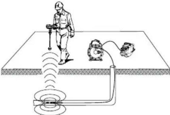
Locating the Sonde
If used with a sonde (In-Line Transmitter), the sonde can be controlled two ways. If the reel is equipped with a sonde key, that can be used to turn the sonde ON and OFF. Otherwise, the sonde is turned ON by decreasing LED brightness to zero. Once the Sonde has been located, the LEDs can be returned to their normal brightness level to continue the inspection.
A RIDGID locator such as the SR-20, SR-60, Scout ® , or NaviTrack ® II set to 512 Hz can be used to locate features in the drain being inspected.
natural_image
Diagram of a person using a handheld device to detect a ground level with a sensor and motor (no text or labels)Figure 19 – Locating the Reel Sonde
To locate the Sonde, turn the locator ON and set it to Sonde mode. Scan in the direction of the Sonde's probable location until the locator detects the Sonde. Once you have detected the Sonde, use the locator indications to zero in on its location precisely. For detailed instructions on Sonde locating, consult the Operator's Manual for the locator model you are using.
Maintenance
WARNING
Remove battery before cleaning.
• Always clean the imager head and cable after use with mild soap or mild detergent.
• Gently clean the display screen with a clean dry cloth. Avoid rubbing too hard.
- Use only alcohol swabs to clean the cable connections.
- Wipe the hand held display unit down with a clean, dry cloth.
Reset Function
If the unit stops functioning and does not operate, press the Reset Button (under the left side port cover – Figure 4). The unit may recover to normal operation when re started.
Optional Equipment
WARNING
To reduce the risk of serious injury, only use equipment specifically designed and recommended for use with the RIDGID micro CA-350 Inspection Camera such as those listed below. Other equipment suitable for use with other tools may be hazardous when used with the micro CA-350 Inspection Camera.
| Catalog No. | Description |
| 37108 3' | (90 cm) Cable Extension |
| 37113 6' | (180 cm) Cable Extension |
| 37103 Imager Head and Cable - 17 mm | |
| 37098 1 m length 6mm diameter imager | |
| 37093 4 m length 6mm diameter imager | |
| 37123 17 mm Accessory Pack (Hook, Magnet, Mirror) | |
| 36758 AC Adapter | |
| 40623 Headset Accessory with Microphone | |
RBC-121 Chargers and Cords
| Catalog No. | Region Plug Type | ||
| 55193 | Charger | USA, Canada and Mexico | A |
| 55198 | Charger | Europe | C |
| 55203 | Charger | China | A |
| 55208 | Charger | Australia & Latin America | I |
| 55213 | Charger | Japan | A |
| 55218 | Charger | United Kingdom | G |
| 44798 | Charger Cord | North America | A |
| 44808 | Charger Cord | Europe | C |
| 44803 | Charger Cord | China | A |
| 44813 | Charger Cord | Australia & LA | I |
| 44818 | Charger Cord | Japan | A |
| 44828 | Charger Cord | United Kingdom | G |
Batteries
| Catalog No. | Model | Capacity |
| 55183 | RB-1225 | 12V 2.5Ah |
All listed batteries will work with any catalog number RBC-121 Battery Charger.
For a complete listing of RIDGID equipment available for this tool, see the Ridge Tool Cata log online at RIDGID.com or call Ridge Tool Technical Services 844-789-8665.
Storage
The RIDGID micro CA-350 Inspection Camera must be stored in a dry secure area between -4°F (-20°C) and 140°F (60°C) and humidity between 15% and 85% RH.
Store the tool in a locked area, out of the reach of children and people unfamiliar with the micro CA-350 Inspection Cam era.
Remove the battery before storage or shipping.
Service and Repair
WARNING
Improper service or repair can make the RIDGID micro CA-350 Inspection Camera unsafe to operate.
Service and repair of the micro CA-350 In spec tion Camera must be performed by a RIDGID Authorized In dependent Service Center.
For information on your nearest RIDGID Authorized In dependent Service Center or any service or repair questions:
- Contact your local RIDGID distributor.
- Visit RIDGID.com to find your local RIDGID contact point.
- Contact Ridge Tool Technical Service Department at ProToolsTechService@Emerson.com, or in the U.S. and Canada call 844-789-8665.
Disposal
Parts of the RIDGID micro CA-350 Inspection Camera contain valuable materials and can be recycled. There are companies that specialize in recycling that may be found locally. Dispose of the com ponents in compliance with all applicable regulations. Contact your local waste management authority for more information.
For EC Countries: Do not dispose of elec trical equipment with household waste!
According to the European Guideline 2012/ 19/EU for Waste Electrical and Electronic Equipment
and its imple men tation into national legis- lation, electrical equipment that is no lon- ger usable must be collected separately and disposed of in an environmentally correct manner.
Troubleshooting
| SYMPTOM POSSIBLE REASON SOLUTION | ||
| Display turns ON, but does not show image. | Loose cable connections. | Check cable connections, clean if required. Re-attach. |
| Imager is broken. | Replace the Imager. | |
| Imager head covered by debris. | Visually inspect imager head to make certain it is not covered by debris. | |
| LEDs on imager head are dim at max brightness, display switches between black and white, color display turns itself OFF after a brief period. | Battery low on power. | Replace battery with charged battery. |
| Unit will not turn ON. | Dead battery. | Replace with charged battery. |
| Unit need to be reset. | Reset unit. See “Maintenance” Section. | |
natural_image
Black and white photo of an endoscopic RIOGID remote device with a coiled cable, no visible text or symbols on the device itself.
AVERTISSEMENT
CONSERVEZ CES INSTRUCTIONS!
natural_image
Collection of electronic devices including a monitor, earbuds, and charging case (no visible text or labels)Figure 2 – Commandes
natural_image
Close-up of a hand holding a cylindrical device with visible internal components and arrows pointing to it (no text or symbols)Figure 5 – Retrait/introduction de la pile
natural_image
Close-up of two black mechanical components, one cylindrical and one flanged, against a white background (no visible text or symbols)natural_image
Close-up of a hand inserting a card into a device (no visible text or symbols)Figure 9 – Introduction de la carte SD
natural_image
Three black-and-white icons representing security, cybersecurity, and gear (no text or symbols)natural_image
Three black-and-white icons: a stick figure with motion lines, a circular symbol with eyes and a gear, and a broken tool (no text or symbols)natural_image
Close-up of a handheld electronic device labeled 'RIOGID' with no visible text or symbols on its body.natural_image
Diagram of a person using a handheld device to detect a signal from a sensor or measurement device (no text or labels present)natural_image
Black and white photo of an RIOGIO endoscope device with attached cable, no visible text or symbols on the device itself.
ADVERTENCIA
natural_image
Collection of electronic devices including cables, a handheld device, and a portable device (no visible text or labels)natural_image
Close-up of a hand holding a cylindrical device with visible internal components and arrows pointing to it (no text or symbols)natural_image
Close-up of a hand inserting a resistor into a device labeled 'RIDGID' (no additional text or symbols visible)natural_image
Close-up of two black mechanical components, one cylindrical and one flanged, against a white background (no visible text or symbols)natural_image
Close-up of a hand inserting a card into a device (no visible text or symbols)natural_image
Close-up of a mechanical tool with visible branding (no readable text or symbols)natural_image
Diagram of a person using a handheld device to detect a signal from a sensor array and motor (no text or labels)natural_image
RiDGD 12V endoscope device with visible control panel and cable (no text or symbols on device body)WARNING!
natural_image
Assorted electronic devices including a handheld device, cable, and charging case (no visible text or labels)natural_image
Close-up of a hand holding a cylindrical device with warning labels and arrows indicating assembly (no readable text or symbols)natural_image
Close-up of a hand inserting a component into an RIOGID device (no visible text or symbols on the device body)natural_image
Close-up of two black industrial pipe fittings with visible branding (no text or symbols on the main subject)natural_image
Close-up of a hand inserting a 3G RAM card into a device (no visible text or symbols on the card or background)natural_image
Three black-and-white icons representing physical and technical symbols: a person running with tools, a gear with eyes, and a gear with gears (no text or labels)natural_image
Three black-and-white icons: a running figure, a circular symbol with eyes, and a gear with gears (no text or symbols)natural_image
Close-up of a black RIOGID electric drill press tool being held, no visible text or symbols on the device itself.natural_image
Diagram of a person using a handheld device to detect a signal from a detection device (no text or labels)natural_image
RiDGD 12V endoscope device with visible control panel and cable (no text or symbols on device body)WAARSCHUWING!
natural_image
Assorted electronic devices including a handheld device, earplifier, and cable accessories (no visible text or labels)natural_image
Close-up of hands inserting a plastic electrical plug into a device labeled 'RiC20 124' (no readable text beyond label)natural_image
Close-up of a person using an RIDGID handheld device to press or install a cable, no visible text or symbols on the device itself.natural_image
Close-up of a black mechanical component with a cylindrical shaft and a cylindrical connector (no visible text or symbols)Figuur 7 – Kabelverbindingen
natural_image
Close-up of a hand inserting a KB card into a device (no visible text or symbols on the card or background)natural_image
Close-up of a person using a R1DGID power tool, no visible text or symbols on the device itself.natural_image
Diagram of a person using a handheld device to detect a detection or signal system, with no visible text or symbols.natural_image
RiDGD 12V endoscope device with visible control panel and cable (no text or symbols on device body)ATTENZIONE!
natural_image
Collection of electronic testing equipment including a handheld device, cable, and earplugs (no visible text or labels)natural_image
Close-up of a hand holding a cylindrical device with warning labels and arrows indicating assembly (no readable text or symbols)natural_image
Close-up of a hand inserting a black cable into an RIOGID device (no visible text or symbols on the device body)natural_image
Close-up of two black industrial pipe fittings with visible branding (no text or symbols on the main subject)natural_image
Close-up of a hand inserting a KB card into a device (no visible text or symbols on the card or background)natural_image
Three black-and-white icons representing human, circular, and gear symbols (no text or labels)natural_image
Three black-and-white icons: a stick figure holding a megaphone, a gear with eyes, and a gear with tools (no text or symbols)natural_image
Close-up of a person using a RIDGID power tool, no visible text or symbols on the device itself.natural_image
Diagram of a person using a handheld device to detect signal waves from a detection device on a flat surface (no text or symbols present)natural_image
RiDGD 12V endoscope device with visible control panel and cable (no text or symbols on device body)! AVISO!
natural_image
Assorted electronic devices including a handheld device, cable, and earplifier (no visible text or labels)natural_image
Close-up of a hand inserting a plastic cylindrical device into a black plastic housing (no visible text or symbols)Figura 5 – Remover/instalar a Bateria
natural_image
Close-up of a hand inserting a USB into an RIOGID device (no visible text or symbols on the device body)natural_image
Close-up of two black industrial pipe fittings with visible branding (no text or symbols on the main subject)natural_image
Close-up of a hand inserting a 3G RAM into a device (no visible text or symbols on the chip or background)natural_image
Close-up of a black RIOGID tool being held, no visible text or symbols on the device itself.natural_image
Diagram of a person using a handheld device to detect a circular object on a flat surface, with a motor and sensor nearby (no text or symbols)Figura 19 – Localizar a Sonda Reel
natural_image
Ridgid remote control device with visible display and cable, no text or symbols on the device itselfWARNING!
natural_image
Collection of electronic devices including a handheld device, cable, and charging case (no visible text or labels)Figur 1 – micro CA-350 inspektionskamera
Reglage
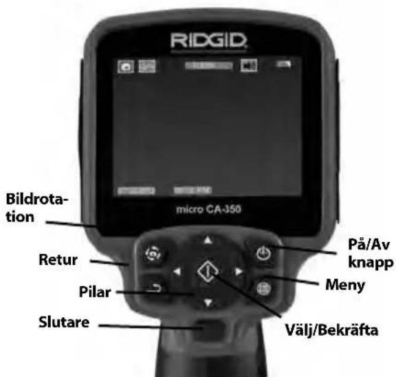
Figur 2 - Reglage
natural_image
Close-up of hands inserting a plastic electrical plug into a battery pack (no visible text or symbols)natural_image
Close-up of a person inserting a resistor into a RIDGID device (no visible text or symbols on the device body)natural_image
Close-up of two black industrial pipe fittings with visible branding (no text or symbols on the main subject)Figur 7 – Kabelanslutningar
natural_image
Close-up of a hand inserting a KB card into a device (no visible text or symbols on the card or body)natural_image
Three black-and-white icons representing security, protection, and gear (no text or symbols)natural_image
Close-up of a person using a RIDGID power tool, no visible text or symbols on the device itself.Figur 18 – Kamerans anslutningskontakt ansluten
natural_image
Diagram of a person using a handheld device to detect signal waves from a sensor array (no text or labels)Figur 19 – Lokalisera sonden
natural_image
RiDGD 12V endoscope device with visible control panel and cable (no text or symbols on device body)ADVARSEL!
natural_image
Assorted electronic devices including a handheld device, earplifier, and charging case (no visible text or labels)Figur 1 - micro CA-350-inspektionskamera
Kontrolanordninger
natural_image
Close-up of a hand holding a cylindrical device with warning labels and arrows indicating process (no readable text or symbols)Figur 5 – Fjernelse/Installation af batteriet
natural_image
Close-up of a hand inserting a USB into an RIOGID device (no visible text or symbols on the device body)natural_image
Close-up of two black industrial pipe fittings with no visible text or symbolsFigur 7 – Kabelforbindelser
natural_image
Close-up of a hand inserting a 8GB memory card into a device (no visible text or symbols on the card)natural_image
Close-up of a black RIOGID power tool with attached probe, no visible text or symbols on the device itself.Figur 18 - Kamerastik installeret
natural_image
Diagram of a person using a handheld device to detect a signal from a sensor array (no text or labels)natural_image
RiDGD 12V endoscope device with visible control panel and cable (no text or symbols on device body)ADVARSEL!
natural_image
Assorted electronic devices including a handheld device, cable, and charging case (no visible text or labels)natural_image
Close-up of a hand holding a cylindrical device with warning labels and arrows indicating assembly (no readable text or symbols)Figur 5 – Fjerne/installere batteriet
natural_image
Close-up of a hand inserting a USB into an RIOGID device (no visible text or symbols on the device body)Figur 6 – Drive enheten med VS-adapter
natural_image
Close-up of a black RIOGID tool connector and a mechanical component (no visible text or symbols)Figur 7 – Kabelkoplinger
natural_image
Close-up of a hand inserting a 3G RAM card into a device (no visible text or symbols)natural_image
Close-up of a person using a RIDGID power tool, no visible text or symbols on the device itself.Figur 18 – Kameraets tilkoplingsplugg installert
natural_image
Diagram of a person using a handheld device to detect a signal from a sensor or measurement device (no text or labels present)Figur 19 – Lokalisering av Reel-sonden
natural_image
RiDGD 12V endoscope device with visible control panel and cable (no text or symbols on device body)! VAROITUS!
natural_image
Assorted electronic devices including a handheld device, cable, earplugs, and charging case (no visible text or labels)natural_image
Close-up of a hand holding an open fuse component with warning labels (no readable text or symbols)natural_image
Close-up of a hand inserting a USB into an R1DGID device (no visible text or symbols on the device body)natural_image
Close-up of two black industrial pipe fittings with visible branding (no text or symbols on the main subject)natural_image
Close-up of a hand inserting a 3G memory card into a device (no visible text or symbols on the card body)natural_image
Close-up of a person using a RIDGID power tool, no visible text or symbols on the device itself.natural_image
Diagram of a person using a handheld device to detect a signal from a sensor array (no text or labels)natural_image
RiDGD 12V endoscope device with visible control panel and cable (no text or symbols on device body)OSTRZEŻENIE!
natural_image
Assorted electronic devices including a handheld device, earplifier, and cable accessories (no visible text or labels)natural_image
Close-up of a hand holding an open electrical plug with warning labels and arrows indicating disassembly (no readable text or symbols)natural_image
Close-up of a hand inserting a USB into an RIOGID device (no visible text or symbols on the device body)natural_image
Close-up of two black industrial pipe fittings with no visible text or symbolsnatural_image
Close-up of a hand inserting a 3G S20 memory card into a device (no visible text or symbols on the card body)natural_image
Close-up of a person using a RIDGID power tool, no visible text or symbols on the device itself.natural_image
Diagram of a person operating a handheld device on a flatbed surface with a motor and sensor array (no text or symbols)natural_image
RiDGD 12V endoscope device with visible control panel and cable (no text or symbols on device body)VAROVÁNÍ!
natural_image
Assorted electronic devices including a handheld device, cable, and earplifier (no visible text or labels)natural_image
Close-up of a hand holding a cylindrical device with warning labels and arrows indicating assembly (no readable text or symbols)natural_image
Close-up of a hand inserting a USB into an R1DGID device (no visible text or symbols on the device body)natural_image
Close-up of two black industrial pipe fittings with no visible text or symbolsnatural_image
Close-up of a hand inserting a 8GB memory card into a device (no visible text or symbols on the card body)natural_image
Close-up of a black R1DGID power tool being held, no visible text or symbols on the device itself.natural_image
Diagram of a person using a handheld device to detect a signal from a sensor array (no text or labels)natural_image
Ridgid 12V endoscope device with visible control panel and cable (no text or symbols on device body)VÝSTRAHA!
TIETO POKYNY USCHOVAJTE!
TIETO POKYNY USCHOVAJTE!
natural_image
Assorted electronic devices including a handheld device, cable, and earplugs arranged on a plain surface (no text or symbols visible)natural_image
Close-up of hands inserting a device into a black plastic housing (no visible text or symbols)natural_image
Close-up of a person using an RIDGID handheld device with a cable inserted, showing control panel and buttons (no readable text or symbols)natural_image
Close-up of two black industrial pipe fittings with no visible text or symbolsnatural_image
Close-up of a hand inserting a 3GB memory card into a device (no visible text or symbols on the card body)natural_image
Close-up of a black RIOGID power tool being held, no visible text or symbols on the device itself.natural_image
Diagram of a person using a handheld device to detect a circular object on a flat surface, with a motor and sensor nearby (no text or symbols)natural_image
RiDGD 12V endoscope device with visible control panel and cable (no text or symbols on device body)AVERTIZARE!
natural_image
Collection of electronic testing equipment including a handheld device, cable, and earplugs (no visible text or labels)natural_image
Close-up of a hand holding an open electrical plug with warning labels and arrows indicating disassembly (no readable text or symbols)natural_image
Close-up of a hand inserting a USB into an R1DGID device (no visible text or symbols on the device body)natural_image
Close-up of two black industrial pipe fittings with visible branding (no text or symbols on the main subject)natural_image
Close-up of a hand inserting a 8GB memory card into a device (no visible text or symbols on the card body)natural_image
Close-up of a person using a RIOGID power tool, no visible text or symbols on the device itself.natural_image
Diagram of a person using a handheld device to detect a surface with a sensor and motor (no text or labels)natural_image
RiDGD 12V endoscope device with visible control panel and cable (no text or symbols on device body)VIGYÁZAT!
natural_image
Collection of electronic devices including a handheld device, cable, and charging case (no visible text or labels)natural_image
Close-up of a hand holding a cylindrical container with warning labels and arrows indicating process (no readable text or symbols)natural_image
Close-up of a hand inserting a USB into an R1DGID device (no visible text or symbols on the device body)natural_image
Close-up of a black plastic tool with a connector and a mechanical component (no visible text or symbols)natural_image
Close-up of a hand inserting a 3G memory card into a device (no visible text or symbols on the card body)natural_image
Close-up of a black RIOGID tool being inserted into a cylindrical component (no visible text or symbols on the tool itself)natural_image
Diagram of a person using a handheld device to detect a signal from a sensor array (no text or labels)natural_image
RiDGD 12V endoscope device with visible control panel and cable (no text or symbols on device body)⚠️ ПРОЕІДОПОІНЄН!
natural_image
Collection of electronic devices including a handheld device, cable, and charging case (no visible text or labels)natural_image
Close-up of a hand holding an open battery with warning labels and arrows indicating disassembly (no readable text or symbols)natural_image
Close-up of a hand inserting a USB into an RIOGID device (no visible text or symbols on the device body)natural_image
Close-up of a black mechanical component with a connector, showing no visible text or symbols.natural_image
Close-up of a hand inserting a 8GB KIPPROM card into a device (no visible text or symbols on the card body)natural_image
Close-up of a black RIOGID power tool with attached probe (no visible text or symbols on the device body)natural_image
Diagram of a person using a handheld device to detect a ground level with an electric motor and sensor array (no text or labels)natural_image
RiDGD 12V endoscope device with visible control panel and cable (no text or symbols on device body)
UPOZORENJE!
SACUVAJTE OVE UPUTE!
natural_image
Assorted electronic devices including a handheld device, cable, and charging case (no visible text or labels)Slika 1 - Kamera za pregled micro CA-350
Komande

Slika 2 - Komande
natural_image
Close-up of a hand holding an open electrical plug with warning labels and arrows indicating disassembly (no readable text or symbols)Slika 5 - Vađenje/umetanje baterije
- Umetnite kraj baterije s kontaktima u alat za pregled, kao što je prikazano na slici 5.
Napajanje pomoću AC adaptera
natural_image
Close-up of a hand inserting a USB into an R1DGID device (no visible text or symbols on the device body)Slika 6 - Napajanje uređaja pomoću AC adaptera
natural_image
Close-up of a black plastic pipe fitting with a connector, next to a larger mechanical component (no visible text or symbols)Slika 7 - Spajanje kabela
Produžnim kabelima 3' (90 cm) i 6' (180 cm) možete produžiti duljinu kabela kamere do 30 stopa (9 metara). Za montažu produžnog kabela prvo razdvojite kabel kamere od jedinice sa zaslonom otpuštanjem nazubljenog gumba. Priključite produžni kabel na ručnu jedinicu kako je gore opisano (slika 7). Utaknite jezičac kabela glave kamere u utor produžnog kabela, prstima stegnite nazubljeni gumb te tako učvrstite spoj.
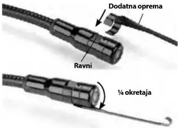
Montaža dodatne opreme
Sva tri priložena dodatka (kuka, magnet i zr- calo) pričvršćuju se na glavu vizualizatora na isti način.
natural_image
Close-up of a hand inserting a 8GB S40 memory card into a device (no visible text or symbols on the card body)Slika 9 - Umetanje SD kartice
Slika 15 – Podešavanje zuma
natural_image
Close-up of a person using a RIDGID power tool, no visible text or symbols on the device itself.Slika 18 - Montirani priključni utikač kamere
NAPOMENA Nemojte savijati priključni utikač kako se ne bi oštetio.
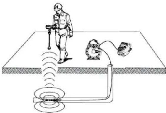
Lociranje sonde
Ako upotrebljavate sondu (žični odašiljač), možete je kontrolirati na dva načina. Ako je kolut opremljen tipkom za sondu, njime je možete UKLJUČITI i ISKLJUČITI. Inače sonda se UKLJUČUJE smanjivanjem svjetline LED lampica na nulu. Kada jednom locirate sondu, možete vratiti LED lampice na normalnu razinu svjetline te nastaviti s pregledom.
RIDGID lokatori kao što su SR-20, SR-60, Scout ili Navi Track® II namješteni na 512 Hz mogu se upotrijebiti za lociranje karakteristika u odvodu koji se pregledava.
natural_image
Diagram of a person using a handheld device to detect a signal from a sensor array (no text or labels)Slika 19 - Lociranje namatajuće sonde
natural_image
RiDGD 12V endoscope device with visible control panel and cable (no text or symbols on device body)OPOZORILO!
natural_image
Assorted electronic devices including a handheld device, cable, and earplifier (no visible text or labels)natural_image
Close-up of hands inserting a black plastic component into a cylindrical device (no visible text or symbols)natural_image
Close-up of a person using an RIDGID handheld device to press or install a cable, no visible text or symbols on the device itself.natural_image
Close-up of a black plastic mechanical component with a connector, next to a close-up of its tip (no visible text or symbols)Slika 7 – Kabelske povezave
natural_image
Close-up of a hand inserting a 3G RAM into a device (no visible text or symbols on the chip or background)natural_image
Close-up of a black RIOGID power tool being held, no visible text or symbols on the device itself.natural_image
Diagram of a person using a handheld device to detect a signal from a sensor array (no text or labels)natural_image
RiDGD 12V endoscope device with visible control panel and cable (no text or symbols on device body)UPOZORENJE!
Pažljivo pročitajte uputstva pre korišćenja ovog alata. Nepoznavanje i nepridržavanje uputstava iz ovog priručnika može imati za posledicu strujni udar, požar i/ili teške telesne povrede.
natural_image
Assorted electronic devices including a handheld device, cable, and charging case (no visible text or labels)Slika 1 - micro CA-350 kamera za pregled
natural_image
Close-up of hands inserting a plastic component into a black plastic housing (no visible text or symbols)Slika 5 - Uklanjanje/ugradnja baterije
- Ubacite kraj kontakta baterije u alat za proveru, kako je prikazano na slici 5.
Napajanje sa mrežnim adapterom.
natural_image
Close-up of a hand inserting a resistor into a R1DG ID device (no visible text or symbols on the device body)Slika 6 - Napajanje uređaja sa mrežnim adapterom
natural_image
Close-up of two black industrial pipe fittings with visible branding (no text or symbols on the main subject)Slika 7 - Spajanje sajle
Nastavci sajle od 3' (90 cm) i 6' (180 cm) su na raspolaganju da bi se omogućilo povećanje dužine sajle vaše kamere do 30 stopa (9 metara). Da bi ugradili nastavak, prvo uklonite sajlu glave kamere sa displej jedinice tako što ćete otpustiti izbočeno dugme. Spojite nastavak na prenosnu displej jedinicu kao što je opisano iznad (slika 7). Spojite provlakač sajle glave kamere na prorez nastavka i prstom stegnite izbočeno dugme da bi zadržali spoj na svom mestu.
natural_image
Close-up of a hand holding a smartphone card with visible internal components (no readable text or symbols)Slika 9 - Umetanje SD kartice
Pregled pre upotrebe
UPOZORENJE

Pre svake upotrebe pregledajte svoju kameru za pregled i otklonite sve probleme da biste smanjili rizik od teške povrede usled strujnog udara i drugih uzroka i sprečili oštećenje alata.
- Vodite računa da je uređaj isključen.
- Uklonite bateriju i proverite ga na znake oštećenja. Zemenite bateriju ako je potrebno. Nemojte koristiti kameru za pregled ako je baterija oštećena.
- Očistite bilo koje ulje, mast ili prljavštinu sa opreme. Ovo olakšava pregled i pomaže u zaštiti alata od klizanja u vašim rukama.
- Proverite da li u micro CA-350 kameri za pregled ima napuklih, pohabanih, nedostajućih, pogrešno spojenih delova ili drugih stanja koja mogu sprečiti siguran i normalan rad.
- Proverite da na sočivima glave kamere nema kondenzacije. Da bi sprečili oštećenje uređaja, nemojte koristiti kameru ako sa unutrašnje strane sočiva postoji kondenzat. Omogućite da voda ispari pre korišćenja.
- Proverite kompletnu dužinu kabla na naprsline i oštećenja. Oštećeni kabl može omogućiti prodor vode u uređaj i povećati rizik od električnog udara.
- Proverite i uverite se da su priključci između prenosne jedinice, kablova nastavaka i kabla sa glavom kamere čvrsti. Svi priključci moraju biti propisno sastavljeni da bi kabl bio nepropusan za vodu. Potvrdite da li je uređaj ispravno sastavljen.
- Proverite da li postoji nalepnica sa upozorenjem i da li je čvrsto učvršćena i čitljiva (slika 10).
natural_image
Close-up of a person using a RIDGID power tool, no visible text or symbols on the device itself.natural_image
Diagram of a person using a handheld device to detect a signal from a sensor or measurement device (no text or labels present)natural_image
Ridgid 12V endoscope device with visible control panel and cable (no text or symbols on device body)ВНИМАНИЕ!
natural_image
Assorted electronic devices including a handheld device, cable, and earplifier (no visible text or labels)natural_image
Close-up of a hand holding a cylindrical device with warning labels and arrows indicating assembly (no readable text or symbols)natural_image
Close-up of a hand inserting a USB into an R1DGID device (no visible text or symbols on the device body)natural_image
Close-up of two black industrial pipe fittings with visible branding (no text or symbols on the main subject)natural_image
Close-up of a hand inserting a 3G RAM card into a device (no visible text or symbols on the card or background)natural_image
Three black-and-white icons representing physical and technical symbols: a person holding a tool, a gear with eyes, and a gear with tools (no text or labels)natural_image
Close-up of a black RIOGID electric drill press tool being held, no visible text or symbols on the device itself.natural_image
Diagram of a person using a handheld device to detect a ground level with an electric motor connected via tubing (no text or labels)natural_image
RiDGD 12V endoscope device with visible wiring and control panel (no text or symbols on device body)! UYARI
natural_image
Assorted electronic devices including a handheld device, cable, and charging case (no visible text or labels)natural_image
Close-up of a hand holding a cylindrical electronic device with warning labels and arrows indicating components (no readable text or symbols)natural_image
Close-up of a hand inserting a USB into an RIOGID device (no visible text or symbols on the device body)natural_image
Close-up of two black industrial pipe fittings with visible branding (no text or symbols on the main subject)natural_image
Close-up of a hand inserting a 3G SGB memory card into a device (no visible text or symbols on the card body)natural_image
Close-up of a black RIOGID power tool with a hand holding it (no visible text or symbols on the device body)natural_image
Diagram of a person using a handheld device to detect signal waves from a sensor array (no text or labels)natural_image
RiDGD 12V endoscope device with visible control panel and cable (no text or symbols on device body)
ECKEPTY!
natural_image
Assorted electronic devices including a remote control, earplugs, and a speaker unit (no visible text or labels)natural_image
Close-up of a hand holding a cylindrical device with warning labels and arrows indicating assembly (no readable text or symbols)natural_image
Close-up of a hand inserting a USB into an R1DGID device (no visible text or symbols on the device body)natural_image
Close-up of two black industrial pipe fittings with visible branding (no text or symbols on the main subject)natural_image
Close-up of a hand inserting a CD-ROM into a device (no visible text or symbols on the card or casing)natural_image
Three black-and-white icons representing security or hazard symbols: a person running with a tool, a circular object with a shield, and a gear with gears (no text or labels)natural_image
Close-up of a black R1DGID power tool with attached screwdriver (no visible text or symbols)natural_image
Diagram of a person using a handheld device to interact with an electric motor and sensor array (no text or labels)RIDGID® micro CA-350 Inspection Camera
MANUFACTURER AUTHORIZED REPRESENTATIVE
RIDGE TOOL COMPANY Ridge Tool Europe NV 400 Clark Street Ondernemerslaan 5428
Elyria, Ohio 44035-6001 3800 Sint-Truiden, Belgium U.S.A.
ProToolsRegulatory.Compliance@Emerson.com +40 374132035
europeproductcompliance@emerson.com
EU/UKCA DECLARATION OF CONFORMITY
We declare that the machines listed above, when used in accordance with the operator's manual, meet the relevant requirements of the Directives and Standards listed below.
DÉCLARATION DE CONFORMITÉ UE
For Warranty Information for your World Region visit RIDGID.com
Ridge Tool Europe N.V.
©2016, 2025 Ridge Tool Company
Printed 425 999-995-087.09
ECN004309 REV. E
RIDGID and the Emerson logo are registered trademarks of Emerson Electric Co. or its subsidiaries in the US and other countries.
Any other trademarks belong to their respective holders.

- Table of Contents
- General Safety Information
- Specific Safety Information
- Description, Specifications and Standard Equipment
- Electromagnetic Compatibility (EMC) 6
- Tool Assembly
- Tool and Work Area Set-Up....8
- Operating Instructions....9
- Maintenance
- Optional Equipment 14
- Storage 14
- Service and Repair 14
- Disposal....15
- Troubleshooting....16
- Declaration of Conformity....Inside Back Cover
- Lifetime Warranty....Back Cover
- micro CA-350 Inspection Camera
- WARNING!
- Safety Symbols
- DANGER
- WARNING
- CAUTION
- SAVE THESE INSTRUCTIONS!
- Work Area Safety
- Electrical Safety
- Personal Safety
- Equipment Use and Care
- Battery Use & Care
- Service
- micro CA-350 Inspection Camera Safety
- Description
- Specifications
- Standard Equipment
- FCC Statement
- Electromagnetic Compatibility (EMC)
- Changing/Installing Batteries
- Powering with the AC Adapter
- Installing the Imager Head Cable or Extension Cables
- Installing Accessories
- Installing SD™ Card
- Pre-Operation Inspection
- Tool and Work Area Set-Up
- Check work area for:
- - Adequate lighting
- Operating Instructions
- Live Screen
- Image Adjustment
- Image Capture
- Capturing a Still Image
- Capturing a Video
- Menu
- Playback Mode
- Deleting Files
- Time Stamp
- Language
- Date/Time
- TV-Out
- Update Firmware
- Speaker
- Auto Power Off
- Factory Reset
- About ?
- Transferring Images to a Computer
- Connecting to TV
- Use with SeeSnake® Inspection Equipment
- Locating the Sonde
- Remove battery before cleaning.
- Reset Function
- Optional Equipment
- Storage
- Service and Repair
- Disposal
- AVERTISSEMENT
- CONSERVEZ CES INSTRUCTIONS!
- ADVERTENCIA
- WAARSCHUWING!
- ATTENZIONE!
- ! AVISO!
- ADVARSEL!
- Kontrolanordninger
- ! VAROITUS!
- OSTRZEŻENIE!
- VAROVÁNÍ!
- VÝSTRAHA!
- TIETO POKYNY USCHOVAJTE!
- AVERTIZARE!
- VIGYÁZAT!
- ⚠️ ПРОЕІДОПОІНЄН!
- UPOZORENJE!
- SACUVAJTE OVE UPUTE!
- Komande
- Slika 5 - Vađenje/umetanje baterije
- Napajanje pomoću AC adaptera
- Slika 7 - Spajanje kabela
- Montaža dodatne opreme
- Lociranje sonde
- OPOZORILO!
- Napajanje sa mrežnim adapterom.
- Slika 7 - Spajanje sajle
- Pregled pre upotrebe
- ВНИМАНИЕ!
- ! UYARI
- ECKEPTY!
- RIDGID® micro CA-350 Inspection Camera
- MANUFACTURER AUTHORIZED REPRESENTATIVE
- EU/UKCA DECLARATION OF CONFORMITY
- DÉCLARATION DE CONFORMITÉ UE
- For Warranty Information for your World Region visit RIDGID.com
Brand : RIDGID
Model : SeeSnake microREEL CA350
Category : Inspection camera