
GCM 18V254 D Professional - Saw BOSCH - Free user manual and instructions
Find the device manual for free GCM 18V254 D Professional BOSCH in PDF.
 FR
FR
 BG
BG
 CS
CS
 DA
DA
 DE
DE
 EL
EL
 EN
EN
 ES
ES
 ET
ET
 FI
FI
 HU
HU
 IT
IT
 KK
KK
 KO
KO
 LT
LT
 LV
LV
 MK
MK
 NL
NL
 NO
NO
 PL
PL
 PT
PT
 RO
RO
 RU
RU
 SK
SK
 SL
SL
 SV
SV
 TR
TR
 UK
UK
| Product type | Cordless sliding compound miter saw |
| Brand | Bosch |
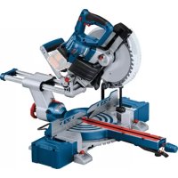
| Model | GCM 18V254 D Professional |
| Power supply | 18 V lithium-ion battery (recommended GBA 18V... or ProCORE18V...) |
| No-load speed | 4,500 rpm |
| Blade diameter | 254 mm |
| Blade arbor | 30 mm (or 25.4 mm with adapter) |
| Blade thickness | 1.4 - 2.5 mm |
| Weight (without battery) | 17.7 - 18.7 kg |
| Laser | Class 2, 650 nm, < 1 mW |
| Miter angle range (horizontal) | -48° to +48° |
| Bevel angle range (vertical) | Left and right (up to 47°) |
| Max cutting capacity (0°/0°) | 90 x 305 mm |
| Min cutting capacity (without clamp) | 100 x 40 mm |
| Main functions | Radial cut (pull), miter cut, bevel cut, laser guide, depth stop for grooves, anti-tilt device, dust extraction |
| Maintenance and cleaning | Regularly clean ventilation slots, pendulum guard, and sliding roller; replace worn chip deflectors; use a brush or compressed air |
| Safety | Pendulum guard, transport lock, transport safety, blade brake, restart protection |
| Spare parts and repairability | Spare parts available via Bosch Service; repair by authorized centers; 10-digit serial number required |
| General information | User manual available in PDF on notice-facile.com; Bosch customer service: 0970821226 (France) |
Frequently Asked Questions - GCM 18V254 D Professional BOSCH
User questions about GCM 18V254 D Professional BOSCH
0 question about this device. Answer the ones you know or ask your own.
Ask a new question about this device
Download the instructions for your Saw in PDF format for free! Find your manual GCM 18V254 D Professional - BOSCH and take your electronic device back in hand. On this page are published all the documents necessary for the use of your device. GCM 18V254 D Professional by BOSCH.
USER MANUAL GCM 18V254 D Professional BOSCH
Original instructions
Original instructions
Ukrainian ... page 258
Kazakh ... page 273
Romanian ... page 288
Bulgarian ... page 302
Macedonian ... page 317
Serbian ... page 332
Slovenian ... page 345
www.bosch-pt.com/serviceaddresses
Transport
General Power Tool Safety Warnings
WARNING
Read all safety warnings, instructions, illustrations and specifications provided with this power tool.
Failure to follow all instructions listed below may result in electric shock, fire and/or serious injury.
Save all warnings and instructions for future reference.
The term "power tool" in the warnings refers to your mains-operated (corded) power tool or battery-operated (cordless) power tool.
Work area safety
- Keep work area clean and well lit. Cluttered or dark areas invite accidents. Do not operate power tools in explosive atmospheres, such as in the presence of flammable liquids, gases or dust. Power tools create sparks which may ignite the dust or fumes.
- Keep children and bystanders away while operating a power tool. Distractions can cause you to lose control.
Electrical safety
Power tool plugs must match the outlet. Never modify the plug in any way. Do not use any adapter plugs with earthed (grounded) power tools. Unmodified plugs and matching outlets will reduce risk of electric shock.
- Avoid body contact with earthed or grounded surfaces, such as pipes, radiators, ranges and refrigerators. There is an increased risk of electric shock if your body is earthed or grounded. Do not expose power tools to rain or wet conditions. Water entering a power tool will increase the risk of electric shock. Do not abuse the cord. Never use the cord for carrying, pulling or unplugging the power tool. Keep cord away from heat, oil, sharp edges or moving parts. Damaged or entangled cords increase the risk of electric shock.
- When operating a power tool outdoors, use an extension cord suitable for outdoor use. Use of a cord suitable for outdoor use reduces the risk of electric shock. If operating a power tool in a damp location is unavoidable, use a residual current device (RCD) protected supply. Use of an RCD reduces the risk of electric shock.
Personal safety
Stay alert, watch what you are doing and use common sense when operating a power tool. Do not use a power tool while you are tired or under the influence of drugs, alcohol or medication. A moment of inattention while operating power tools may result in serious personal injury. Use personal protective equipment. Always wear eye protection. Protective equipment such as a dust mask, non-skid safety shoes, hard hat or hearing protection used for appropriate conditions will reduce personal injuries. Prevent unintentional starting. Ensure the switch is in the off-position before connecting to power source and/or battery pack, picking up or carrying the tool. Carrying power tools with your finger on the switch or energising power tools that have the switch on invites accidents. Remove any adjusting key or wrench before turning the power tool on. A wrench or a key left attached to a rotating part of the power tool may result in personal injury. Do not overreach. Keep proper footing and balance at all times. This enables better control of the power tool in unexpected situations. Dress properly. Do not wear loose clothing or jewellery. Keep your hair and clothing away from moving parts. Loose clothes, jewellery or long hair can be caught in moving parts. If devices are provided for the connection of dust extraction and collection facilities, ensure these are connected and properly used. Use of dust collection can reduce dust-related hazards. Do not let familiarity gained from frequent use of tools allow you to become complacent and ignore tool safety principles. A careless action can cause severe injury within a fraction of a second.
Power tool use and care
Do not force the power tool. Use the correct power tool for your application. The correct power tool will do the job better and safer at the rate for which it was designed. Do not use the power tool if the switch does not turn it on and off. Any power tool that cannot be controlled with the switch is dangerous and must be repaired. Disconnect the plug from the power source and/or remove the battery pack, if detachable, from the power tool before making any adjustments, changing accessories, or storing power tools. Such preventive safety measures reduce the risk of starting the power tool accidentally. Store idle power tools out of the reach of children and do not allow persons unfamiliar with the power tool or these instructions to operate the power tool. Power tools are dangerous in the hands of untrained users. Maintain power tools and accessories. Check for misalignment or binding of moving parts, breakage of parts and any other condition that may affect the power tool's operation. If damaged, have the power tool repaired before use. Many accidents are caused by poorly maintained power tools. Keep cutting tools sharp and clean. Properly maintained cutting tools with sharp cutting edges are less likely to bind and are easier to control. Use the power tool, accessories and tool bits etc. in accordance with these instructions, taking into account the working conditions and the work to be performed. Use of the power tool for operations different from those intended could result in a hazardous situation. Keep handles and grasping surfaces dry, clean and free from oil and grease. Slippery handles and grasping surfaces do not allow for safe handling and control of the tool in unexpected situations.
Battery tool use and care
- Recharge only with the charger specified by the manufacturer. A charger that is suitable for one type of battery pack may create a risk of fire when used with another battery pack. Use power tools only with specifically designated battery packs. Use of any other battery packs may create a risk of injury and fire. When battery pack is not in use, keep it away from other metal objects, like paper clips, coins, keys, nails, screws or other small metal objects, that can make a connection from one terminal to another. Shorting the battery terminals together may cause burns or a fire. Under abusive conditions, liquid may be ejected from the battery; avoid contact. If contact accidentally occurs, flush with water. If liquid contacts eyes, additionally seek medical help. Liquid ejected from the battery may cause irritation or burns.
Do not use a battery pack or tool that is damaged or modified. Damaged or modified batteries may exhibit unpredictable behavior resulting in fire, explosion, or risk of injury. Do not expose a battery pack or tool to fire or excessive temperature. Exposure to fire or temperature above 130°C may cause explosion. Follow all charging instructions and do not charge the battery pack or tool outside the temperature range specified in the instructions. Charging improperly or at temperatures outside the specified range may damage the battery and increase the risk of fire.
Service
Have your power tool serviced by a qualified repair person using only identical replacement parts. This will ensure that the safety of the power tool is maintained. Never service damaged battery packs. Service of battery packs should only be performed by the manufacturer or authorized service providers.
Safety Warnings for Mitre Saws
- Mitre saws are intended to cut wood or wood-like products; they cannot be used with abrasive cut-off wheels for cutting ferrous material such as bars, rods, studs, etc. Abrasive dust causes moving parts such as the lower guard to jam. Sparks from abrasive cutting will burn the lower guard, the kerf insert, and other plastic parts. Use clamps to support the workpiece whenever possible. If supporting the workpiece by hand, you must always keep your hand at least 100 mm from either side of the saw blade. Do not use this saw to cut pieces that are too small to be securely clamped or held by hand. If your hand is placed too close to the saw blade, there is an increased risk of injury from blade contact. The workpiece must be stationary and clamped or held against both the fence and the table. Do not feed the workpiece into the blade or cut "freehand" in any way. Unrestrained or moving workpieces could be thrown at high speeds, causing injury.
- Push the saw through the workpiece. Do not pull the saw through the workpiece. To make a cut, raise the saw head and pull it out over the workpiece without cutting, start the motor, press the saw head down, and push the saw through the workpiece. Cutting on the pull stroke is likely to cause the saw blade to climb on top of the workpiece and violently throw the blade assembly towards the operator.
- Never cross your hand over the intended line of cutting either in front or behind the saw blade. Supporting the workpiece "cross handed" (i.e., holding the workpiece to the right of the saw blade with your left hand or vice versa) is very dangerous. Do not reach behind the fence with either hand closer than 100 mm from either side of the saw blade, to remove wood scraps, or for any other reason while the
blade is spinning. The proximity of the spinning saw blade to your hand may not be obvious and you may be seriously injured.
Inspect your workpiece before cutting. If the workpiece is bowed or warped, clamp it with the outside bowed face toward the fence. Always make certain that there is no gap between the workpiece, fence and table along the line of the cut. Bent or warped workpieces can twist or shift and may cause binding on the spinning saw blade while cutting. There should be no nails or foreign objects in the workpiece. Do not use the saw until the table is clear of all tools, wood scraps, etc., except for the workpiece. Small debris or loose pieces of wood or other objects that contact the revolving blade can be thrown with high speed. Cut only one workpiece at a time. Stacked multiple workpieces cannot be adequately clamped or braced and may bind on the blade or shift during cutting. Ensure the mitre saw is mounted or placed on a level, firm work surface before use. A level and firm work surface reduces the risk of the mitre saw becoming unstable. Plan your work. Every time you change the bevel or mitre angle setting, make sure the adjustable fence is set correctly to support the workpiece and will not interfere with the blade or the guarding system. Without turning the tool "ON" and with no workpiece on the table, move the saw blade through a complete simulated cut to assure there will be no interference or danger of cutting the fence. - Provide adequate support such as table extensions, saw horses, etc. for a workpiece that is wider or longer than the table top. Workpieces longer or wider than the mitre saw table can tip if not securely supported. If the cut-off piece or workpiece tips, it can lift the lower guard or be thrown by the spinning blade. Do not use another person as a substitute for a table extension or as additional support. Unstable support for the workpiece can cause the blade to bind or the workpiece to shift during the cutting operation pulling you and the helper into the spinning blade. The cut-off piece must not be jammed or pressed by any means against the spinning saw blade. If confined, i.e. using length stops, the cut-off piece could get wedged against the blade and thrown violently. Always use a clamp or a fixture designed to properly support round material such as rods or tubing. Rods have a tendency to roll while being cut, causing the blade to "bite" and pull the work with your hand into the blade. Let the blade reach full speed before contacting the workpiece. This will reduce the risk of the workpiece being thrown. If the workpiece or blade becomes jammed, turn the mitre saw off. Wait for all moving parts to stop and disconnect the plug from the power source and/or remove the battery pack. Then work to free the jammed material. Continued sawing with a jammed workpiece could cause loss of control or damage to the mitre saw.
After finishing the cut, release the switch, hold the saw head down and wait for the blade to stop before removing the cut-off piece. Reaching with your hand near the coasting blade is dangerous. Hold the handle firmly when making an incomplete cut or when releasing the switch before the saw head is completely in the down position. The braking action of the saw may cause the saw head to be suddenly pulled downward, causing a risk of injury. Do not let go of the handle once the saw head has reached the lowest position. Always guide the saw head back to the top position by hand. There is a risk of injury if the saw head moves in an uncontrolled manner. Keep your work area clean. Material mixtures are particularly hazardous. Light metal dust may catch fire or explode. Do not use dull, cracked, bent or damaged saw blades. Unsharpened or improperly set saw blades produce narrow kerf causing excessive friction, blade binding and kickback. Do not use saw blades made from high speed steel (HSS). Such saw blades can easily break. Always use saw blades with correct size and shape (diamond versus round) of arbour holes. Saw blades that do not match the mounting hardware of the saw will run off-centre, causing loss of control. Never remove cuttings, wood chips, etc. from the cutting area while the power tool is running. Always guide the tool arm back to the neutral position first and then switch the power tool off. Do not touch the saw blade after working before it has cooled. The saw blade becomes very hot while working. In case of damage and improper use of the battery, vapours may be emitted. The battery can set alight or explode. Ensure the area is well ventilated and seek medical attention should you experience any adverse effects. The vapours may irritate the respiratory system. Do not open the battery. There is a risk of short-circuiting. The battery can be damaged by pointed objects such as nails or screwdrivers or by force applied externally. An internal short circuit may occur, causing the battery to burn, smoke, explode or overheat. Only use the battery in the manufacturer's products. This is the only way in which you can protect the battery against dangerous overload.
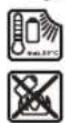
Protect the battery against heat, e.g. against continuous intense sunlight, fire, dirt, water and moisture. There is a risk of explosion and short-circuiting.
The power tool is delivered with a laser warning sign (see table: "Symbols and their meaning"). If the text of the laser warning label is not in your national language, stick the provided warning label in
your national language over it before operating for the first time.
Never make warning signs on the machine unrecognisable.
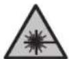
Do not direct the laser beam at persons or animals and do not stare into the direct or reflected laser beam yourself. You could blind somebody, cause accidents or damage your eyes.
If laser radiation hits your eye, you must close your eyes and immediately turn your head away from the beam. Do not make any modifications to the laser equipment. The setting options described in these operating instructions can be used safely. Do not let children use the power tool unsupervised. They could unintentionally blind themselves or other persons.
Symbols
The following symbols may be important for the operation of your power tool. Please take note of these symbols and their meaning. Correctly interpreting the symbols will help you to operate the power tool more effectively and safely.
Symbols and their meaning
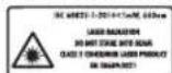
Laser radiation. Do not look directly into the beam. Class 2 consumer laser product EN 50689:2021.

Keep hands away from the cutting area while the power tool is running. Contact with the saw blade can lead to injuries.

Wear a dust mask.
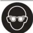
Wear safety goggles.

Wear hearing protection. Exposure to noise can cause hearing loss.

Danger area! Keep hands, fingers and arms away from this area.
Symbols and their meaning
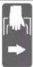
When transporting the power tool, hold it only at the locations indicated (recessed handles) or by the transport handle.
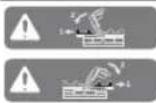
When sawing bevel angles, the adjustable fences must be pulled outwards or removed completely.
3601M511..
3601M511B. 3601M5118.
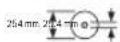
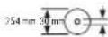
Take note of the dimensions of the saw blade. The hole diameter must match the tool spindle without play. If it is necessary to use reducers, ensure that the dimensions of the reducer are suitable for the base blade thickness and the saw blade hole diameter, as well as the tool spindle diameter. Wherever possible, use the reducers provided with the saw blade.
The saw blade diameter must match the information specified on the symbol.
Product Description and Specifications

Read all the safety and general instructions. Failure to observe the safety and general instructions may result in electric shock, fire and/or serious injury.
Please observe the illustrations at the beginning of this operating manual.
Intended Use
The power tool is intended as a stationary machine for making straight cuts in wood with and against the grain. Mitre angles of -48° to +48° as well as bevel angles of 47° (left-hand side) to 47° (right-hand side) are possible.
The power tool is designed with sufficient capacity for sawing hardwood and softwood as well as chipboard and fibreboard.
When using appropriate saw blades, sawing aluminium profiles and plastic is also possible.
This product is a consumer laser product in accordance with EN 50689.
Product Features
The numbering of the product features refers to the diagram of the power tool on the graphics page.
(1) Locking screw for slide device (2) Slide device (3) Transport handle (4) Protective guard (5) Lock-off function for on/off switch (6) On/off switch
32 | English
(7) Handle (8) Laser protection cap (9) Laser beam outlet aperture (10) Retracting blade guard (11) Guide roller (12) Saw table (13) Mounting holes (14) Insert plate (15) Locking clamp (16) Locking knob for various mitre angles (17) Mitre pre-setting lever (18) Tilt protector (19) Laser warning label (20) Detents for standard mitre angles (21) Scale for mitre angles (22) Clamping screw for saw table extension (23) Saw table extension (24) Workpiece support (flexibly pluggable) (25) Fixed fence (26) Adjustable fence (27) Scale for bevel angle (28) Angle indicator for bevel angles (29) Chip deflector (30) Saw blade (31) Spindle lock (32) Rechargeable battery release button (33) Rechargeable battery (34) Transport safety lock
(35) Tilt protector (36) Length stop (37) Dust bag (38) Depth stop adjusting screw (39) Depth stop (40) Threaded rod (41) Screw clamp (42) Holes for screw clamp (43) Hex key/slotted screwdriver (44) Locking screw for the adjustable fence (45) Clamping wheel for bevel angle (46) Locking lever for bevel angle (47) Opening for workpiece support (on power tool) (48) Opening for second workpiece support (on workpiece support) (49) Threaded bolts (50) Dust extraction adapter (51) Hex socket screw for mounting the saw blade (52) Clamping flange (53) Inner clamping flange (54) Fastening screws for insert plate (55) Screw for laser protection cap (56) Fastening screw for laser housing (57) Laser housing (58) Angle indicator for metre angles (59) Screw for mitre angle indicator (60) Screw for bevel angle indicator (61) Recessed handles
Technical Data
Cordless sliding litre saw GCM 18V-254 D GCM 18V-254 D
| Article number | 3601M511.. 3601M511B. | |
| 3601M5118. | ||
| Rated voltage V= 18 18 | ||
| No-load speedA) | min-1 | 4500 4500 |
| Laser type nm 650 650 | ||
| mW < 1 < 1 | ||
| Laser class 2 2 | ||
| WeightB) | kg 17.7-18.7 17.7-18.7 | |
| Recommended ambient temperature during charging | °C 0 to +35 0 to +35 | |
| Permitted ambient temperature during operationC) and during storage | °C -20 to +50 -20 to +50 | |
| Recommended rechargeable batteries GBA 18V... | GBA 18V... | |
| ProCORE18V... | ProCORE18V... | |
Cordless sliding litre saw GCM 18V-254 D GCM 18V-254 D
| Recommended battery chargers GAL 18... | GAX 18... | GAL 18... |
| GAL 36... | GAX 18... | |
| GAL 36... |
Dimensions of suitable saw blades
| Saw blade diameter mm 254 254 | |
| Base blade thickness mm 1.4-2.5 1.4-2.5 | |
| Hole diameter mm 30 25.4 |
A) Measured at 20 - 25°C with rechargeable battery ProCORE18V 8.0Ah B) Depends on battery in use C) Limited performance at temperatures < 0°C
Values can vary depending on the product, scope of application and environmental conditions. To find out more, visit www.bosch-professional.com/wac.
Permitted workpiece dimensions (maximum/minimum): (see "Permissible workpiece dimensions", page 38)
Noise Information
Noise emission values determined according to EN IEC 62841-3-9.
Typically, the A-weighted noise level of the power tool is: Sound pressure level 97 dB(A); sound power level 106 dB(A). Uncertainty K = 3 dB.
Wear hearing protection!
The noise emission value given in these instructions has been measured in accordance with a standardised measuring procedure and may be used to compare power tools. It may also be used for a preliminary estimation of noise emissions.
The noise emission value given represents the main applications of the power tool. However, if the power tool is used for other applications, with different application tools or is poorly maintained, the noise emission value may differ. This may significantly increase noise emissions over the total working period.
To estimate noise emissions accurately, the times when the tool is switched off, or when it is running but not actually being used, should also be taken into account. This may significantly reduce noise emissions over the total working period.
Rechargeable battery
Bosch sells some cordless power tools without a rechargeable battery. You can tell whether a rechargeable battery is included with the power tool by looking at the packaging.
Charging the battery
Use only the chargers listed in the technical data. Only these chargers are matched to the lithium-ion battery of your power tool.
Note: Lithium-ion rechargeable batteries are supplied partially charged according to international transport regulations. To ensure full rechargeable battery capacity, fully charge the rechargeable battery before using your tool for the first time.
Inserting the Battery
Push the charged battery into the battery holder until it clicks into place.
Removing the Battery
To remove the rechargeable battery, press the battery release button and pull the battery out. Do not use force to do this.
The rechargeable battery has two locking levels to prevent the battery from falling out if the battery release button is pressed unintentionally. The rechargeable battery is held in place by a spring when fitted in the power tool.
Battery charge indicator
Note: Not all battery types have a battery charge indicator.
The green LEDs on the battery charge indicator indicate the state of charge of the battery. For safety reasons, it is only possible to check the state of charge when the power tool is not in operation.
Press the button for the battery charge indicator or to show the state of charge. This is also possible when the battery is removed.
If no LED lights up after pressing the button for the battery charge indicator, then the battery is defective and must be replaced.
Battery model GBA 18V...


LED Capacity
3× continuous green light 60–100%
2× continuous green light 30–60%
1× continuous green light 5–30%
1× flashing green light 0–5%
Battery model ProCORE18V...

LED Capacity
5× continuous green light 80–100% 4× continuous green light 60–80% 3× continuous green light 40–60% 2× continuous green light 20–40% 1× continuous green light 5–20% 1× flashing green light 0–5%
Recommendations for Optimal Handling of the Battery
Protect the battery against moisture and water.
Only store the battery within a temperature range of -20 to 50°C. Do not leave the battery in your car in the summer, for example.
Occasionally clean the ventilation slots on the battery using a soft brush that is clean and dry.
A significantly reduced operating time after charging indicates that the battery has deteriorated and must be replaced. Follow the instructions on correct disposal.
Assembly
- Remove the battery from the power tool before carrying out work on the power tool (e.g. maintenance, changing tool, etc.). The battery should also be removed for transport and storage. There is risk of injury from unintentionally pressing the on/off switch.
Items included

See the list of items included at the start of the operating manual.
Check to ensure that all the parts listed below have been supplied before using the power tool for the first time:
- Sliding litre saw with fitted saw blade
- Clamping wheel (45)
- Adjustable fence (26) Screw clamp (41)
- Hex key/slotted screwdriver (43) Dust bag (37) -Workpiece supports (24) (2 pieces)
Note: Check the power tool for possible damage. Before continuing to use the power tool, carefully check that all protective devices or slightly damaged parts are working perfectly and according to specifications. Check that the moving parts are working perfectly and without jamming; check whether any parts are damaged. All parts must be fitted correctly and all the conditions necessary to ensure smooth operation must be met.
If the protective devices or any parts become damaged, you must have them properly repaired or replaced by an authorised service centre.
Fitting individual components
- Carefully remove all parts included in the delivery from their packaging.
- Remove all packing material from the power tool and the accessories provided.
- For ease of assembly when fitting the tool elements that are provided, be aware that the power tool is supplied in the transport position.
Installing Workpiece Supports (see figure A1)
The workpiece supports (24) can be positioned to the left, right, or in front of the power tool. The flexible connector system enables a multitude of extension or expansion variants (see figure G).
- Insert the workpiece support (24) into the openings (47) on the power tool or into the openings (48) of the second workpiece support as required.
- Never carry the power tool using the workpiece supports. Only use the transport devices to transport the power tool.
Fitting the Clamping Wheel (see figure A2)
The clamping wheel (45) fixes the selected bevel angle and is required for safe operation.
- Unscrew the hex nut from the threaded bolts (49). Screw the clamping wheel (45) clockwise onto the threaded bolts (49) and tighten it.
Fitting the Adjustable Fence (see figure A3)
The adjustable fence (26) must be fitted before sawing. Slide the fence (26) on the right of the saw blade into the corresponding groove and tighten the locking screw (44). The levelled side of the fence must face inwards towards the saw blade.
Stationary or flexible mounting
To ensure safe handling, the power tool must be mounted on a flat, stable work surface (e.g., work bench) before use.
Mounting on a work surface (see figures B1-B2)
- Use suitable screw fasteners to secure the power tool to the work surface. The holes (13) are used for this purpose.
or
- Firmly clamp the base of the power tool to the work surface with commercially available screw clamps.
Mounting on a Bosch saw stand
With the height-adjustable legs, Bosch GTA saw stands provide firm support for the power tool on any surface. The workpiece supports of the saw stand are used for underlaying long workpieces.
Read all the warnings and instructions included with the saw stand. Failure to observe the warnings and follow instructions may result in electric shock, fire and/or serious injury. Assemble the saw stand properly before mounting the power tool. Correct assembly is important to prevent the risk of collapsing. - Mount the power tool on the saw stand in the transport position.
Flexible installation (not recommended) (see figure B3)
If, in exceptional circumstances, it is not possible to mount the power tool on a flat and stable work surface, you can improvise by setting it up with the tilt protector.
Without the tilt protector, the power tool will not be stable and can tip over especially when sawing maximum litre and/or bevel angles. - Rotate the tilt protector (18) inwards or outwards until the power tool is positioned straight on the work surface.
Dust/Chip Extraction
The dust from materials such as lead paint, some types of wood, minerals and metal can be harmful to human health. Touching or breathing in this dust can trigger allergic reactions and/or cause respiratory illnesses in the user or in people in the near vicinity.
Certain dusts, such as oak or beech dust, are classified as carcinogenic, especially in conjunction with wood treatment additives (chromate, wood preservative). Materials containing asbestos may only be machined by specialists.
- Use a dust extraction system that is suitable for the material wherever possible.
- Provide good ventilation at the workplace.
- It is advisable to wear a P2 filter class breathing mask.
The regulations on the material being machined that apply in the country of use must be observed.
- Avoid dust accumulation at the workplace. Dust can easily ignite.
The dust/chip extraction system can be blocked by dust, chips or fragments of the workpiece.
- Switch the power tool off and remove the battery.
- Wait until the saw blade has come to a complete stop.
- Determine the cause of the blockage and eliminate it.
Self-generated dust extraction (see figure C)
For basic chip collection, use the dust bag (37) provided.
- Turn the transport handle (3) so that it is vertical.
- Place the dust bag (37) onto the extraction adapter (50) and turn so that the pin of the dust bag locks in place in the recess of the extraction adapter.
During sawing, the dust bag must not come into contact with moving tool components.
Always empty the dust bag in good time.
Check and clean the dust bag each time after using. When sawing aluminium, remove the dust bag to avoid the risk of fire.
External Dust Extraction
You can also attach a dust extraction hose (35 mm diameter) to the extraction adapter (50) for extraction. Connect the dust extraction hose to the extraction adapter (50).
The dust extractor must be suitable for the material being worked.
When extracting dry dust that is especially detrimental to health or carcinogenic, use a special dust extractor.
Changing the saw blade (see figures D1-D4)
- Remove the battery from the power tool before carrying out work on the power tool (e.g. maintenance, changing tool, etc.). The battery should also be removed for transport and storage. There is risk of injury from unintentionally pressing the on/off switch. Wear protective gloves when fitting the saw blade.
There is a risk of injury when touching the saw blade. Only use saw blades that have a maximum permitted speed higher than the no-load speed of the power tool.
Only use saw blades that match the specifications given in this operating manual and that have been tested and marked in accordance with EN 847-1.
Only use saw blades that are recommended by the power tool manufacturer and are suitable for use on the material you want to saw. This will prevent the saw teeth overheating when sawing.
Removing the Saw Blade
- Bring the power tool into the work position.
- Swivel the retracting blade guard (10) to the back and hold it in this position. Turn the hex socket screw (51) with the hex key (6 mm) (43) and at the same time push the spindle lock (31) until it engages.
- Keep holding the spindle lock (31) and loosen the hex socket screw (51) by turning it clockwise (left-hand thread).
- Remove the clamping flange (52).
- Remove the saw blade (30)
- Slowly push the retracting blade guard back down.
Fitting the saw blade
- When fitting the saw blade, make sure that the cutting direction of the teeth (arrow direction on the saw blade) matches the direction of the arrow on the protective guard.
If required, clean all the parts you want to fit before installing them.
- Swivel the retracting blade guard (10) to the back and hold it in this position.
- Place the new saw blade on the inner clamping flange (53).
- Fit the clamping flange (52) and the hex socket screw (51). Press the spindle lock (31) until it engages
and tighten the hex socket screw by turning it anticlockwise.
- Slowly push the retracting blade guard back down.
Operation
- Remove the battery from the power tool before carrying out work on the power tool (e.g. maintenance, changing tool, etc.). The battery should also be removed for transport and storage. There is risk of injury from unintentionally pressing the on/off switch.
Transport Safety Lock (see figure E)
The transport safety lock (34) makes it easier to handle the power tool when transporting it to various working locations.
Unlocking the power tool (work position)
- Press the tool arm down slightly by the handle (7) to release the transport safety lock (34).
- Pull the transport safety lock (34) all the way out.
- Slowly guide the tool arm upwards.
Locking the power tool (transport position)
- Loosen the locking screw (1) if it is clamping the slide device (2) in place. Pull the tool arm fully forward and tighten the locking screw again to lock the slide device.
- Pull the depth stop (39) upwards.
- To lock the saw table (12) in place, tighten the locking knob (16).
- Swing the tool arm downwards by the handle (7) until you can press the transport safety lock (34) all the way in.
The tool arm is now securely locked and ready for transportation.
Preparing for operation
To ensure precise cuts, the basic settings of the power tool must be checked and adjusted as necessary after intensive use.
Experience and suitable special tools are required for this.
A Bosch after-sales service point will handle this work quickly and reliably.
Extending/Expanding the Saw Table (see figures F-G)
The free end of long and heavy workpieces must have something placed underneath it or be supported.
The saw table can be extended left and right using the saw table extensions (23).
- Loosen the clamping screw (22).
- Pull out the saw table extension (23) to the required length.
- Retighten the clamping screw (22) to fix the saw table extension.
The flexible connector system of the workpiece supports (24) enables a multitude of extension or expansion variants.
- Insert the workpiece support (24) into the openings (47) on the power tool or into the openings (48) of the second workpiece support as required.
- Never carry the power tool using the workpiece supports.
Only use the transport devices to transport the power tool.
Moving the fence (see figure H)
When sawing mitre and/or bevel angles, you have to pull the left-hand or right-hand adjustable fence (26) outwards depending on the cutting direction, or remove it completely.
| Bevel angle Mitre angle | ||
| 0°-22.5°(left/right) | >0° | -Loosen the left-hand/right-hand locking screw (44).-Pull the left-hand/right-hand adjustable fence (26) all the way out. |
| 22.5°-47°(left/right) | ≤48°(left/right) | -Loosen the left-hand/right-hand locking screw (44).-Pull the left-hand/right-hand adjustable fence (26) all the way out.- Lift the adjustable fence upwards and out of the way. |
Clamping the Workpiece (see figure 1)
To ensure maximum safety while working, the workpiece must always be firmly clamped.
Do not saw workpieces that are too small to clamp firmly.
- Press the workpiece firmly against the fences (26) and (25).
- Insert the supplied screw clamp (41) into one of the corresponding holes (42).
- Adjust the threaded rod (40) of the screw clamp to the workpiece height.
- Tighten the threaded rod (40) to fix the workpiece in place.
Adjusting mitre angles
Setting Standard Mitre Angles (see figure J)
For quick and precise setting of commonly used mitre angles, detents (20) are provided on the saw table:
Left Right
0°
45°; 30°; 22.5°; 15° 15°; 22.5°; 30°; 45°
- Loosen the locking knob (16) if it is tightened.
- Pull the lever (17) and rotate the saw table (12) left or right to the required detent.
- Release the lever again. The lever must be felt to engage in the detent.
- Retighten the locking knob (16).
Setting Any Mitre Angle (see figure K)
The mitre angle can be set between 48° (left-hand side) and 48° (right-hand side).
- Loosen the locking knob (16) if it is tightened.
- Pull the lever (17) and at the same time press the locking clamp (15) until this clicks into the slot provided for it. This means the saw table can now move freely. Turn the saw table (12) left or right by the locking knob until the angle indicator (58) shows the required mitre angle.
- Retighten the locking knob (16).
- To loosen the lever (17) again (for setting standard metre angles), pull the lever upwards. The locking clamp (15) springs back into its original position and the lever (17) can click back into the detents (20).
Adjusting bevel angles
The bevel angle can be set between 47° (left-hand side) and 47° (right-hand side).
For quick and precise setting of frequently used bevel angles, fixed positions have been provided for the angles 0° , 22.5° and 45° .
- Make sure that the clamping wheel (45) is fitted (see "Fitting the Clamping Wheel (see figure A2)", page 34).
Setting Standard Bevel Angles (see figure L)
- Pull the adjustable fences (26) all the way out or remove them completely.
- Release the clamping wheel (45).
- Pull the locking lever (46) out and engage it in the free running position.
This enables you to use the complete bevel angle range (left and right).
- Swivel the tool arm left or right by the handle (7) until the angle indicator (28) shows the required standard bevel angle.
- Turn the locking lever (46). The locking lever must be felt to engage in the position of the required standard bevel angle.
- Retighten the clamping wheel (45).
Setting any bevel angle
- Pull the adjustable fences (26) all the way out or remove them completely.
- Release the clamping wheel (45).
- Pull the locking lever (46) out and engage it in the free running position. This enables you to use the complete bevel angle range (left and right).
- Swivel the tool arm left or right by the handle (7) until the angle indicator (28) shows the required bevel angle.
- Retighten the clamping wheel (45).
Start-up
Always tighten the locking knob (16) and the clamping wheel (45) firmly before sawing. Otherwise the saw blade can become wedged in the workpiece.
Switching on (see figure M)
- To switch on the power tool, first slide the lock-off button (5) to the middle and then press and hold the on/off switch (6).
Note: For safety reasons, the on/off switch (6) cannot be locked; it must remain pressed during the entire operation.
Switching off
- To switch off, release the on/off switch (6).
Sawing
General sawing instructions
Always tighten the locking knob (16) and the clamping wheel (45) firmly before sawing. Otherwise the saw blade can become wedged in the workpiece. For all cuts, it must first be ensured that the saw blade at no time can come in contact with the fence, screw clamps or other machine parts. Remove any mounted auxiliary stops or adjust them accordingly.
Protect the saw blade against impact and shock. Do not subject the saw blade to lateral pressure.
Only saw materials which are permitted within the scope of the intended use.
Do not saw warped or bent workpieces. The workpiece must always have a straight edge to face against the fence.
The free end of long and heavy workpieces must have something placed underneath it or be supported.
Make sure that the retracting blade guard operates properly and that it can move freely. The retracting blade guard must open when the tool arm is guided downwards. When the tool arm is guided upwards, the retracting blade guard must close again over the saw blade and lock in the uppermost position of the tool arm.
Position of the operator (see figure N)
Do not stand in line with the saw blade in front of the power tool. Always stand to the side of the saw blade. This protects your body against possible kickback. - Keep hands, fingers and arms away from the rotating saw blade. - Do not reach one hand across the other when in front of the tool arm.
Sawing with slide movement
- For cuts made using the slide device (2) (wide workpieces), loosen the locking screw (1) if it is tightened.
- Set the required metre and/or bevel angle as necessary.
- Press the workpiece firmly against the fences (25) and (26).
- Firmly clamp the workpiece as appropriate for its dimensions.
- Pull the tool arm away from the fence (25) until the saw blade is in front of the workpiece.
- Switch the power tool on.
- Slowly guide the tool arm downwards using the handle (7).
- Now push the tool arm towards the fences (25) and (26) and saw through the workpiece with uniform feed.
- Switch off the power tool and wait until the saw blade has come to a complete stop.
- Slowly guide the tool arm upwards.
Sawing without slide movement (cutting off) (see figure O)
- For cuts without slide movement (small workpieces), loosen the locking screw (1) if it is tightened. Push the tool arm all the way towards the fence (25) and retighten the locking screw (1).
- Set the required miter and/or bevel angle as necessary.
- Press the workpiece firmly against the fences (25) and (26).
- Firmly clamp the workpiece as appropriate for its dimensions.
- Switch the power tool on.
- Slowly guide the tool arm downwards using the handle (7).
- Saw through the workpiece applying uniform feed.
- Switch off the power tool and wait until the saw blade has come to a complete stop.
- Slowly guide the tool arm upwards.
Practical advice
Marking the Cutting Line (see figure P)
Two laser beams indicate the cutting line of the saw blade. This allows for exact positioning of the workpiece for sawing, without having to open the retracting blade guard.
- To do this, switch on the laser beams by briefly pressing the on/off switch (6) without pressing the lock-off button (5).
- Position your mark on the workpiece between the two laser lines.
Note: Before sawing, check if the cutting line is still indicated correctly (see "Adjusting the laser", page 38). Vibrations during intensive use, for example, can cause the laser beams to become misaligned.
Permissible workpiece dimensions
Maximum workpiece dimensions:
Mitre angle Bevel angle Height x width
0° 0° 90 x 305
45° (left/right) 0° 90 x 215
45° (left) 45° (left) 55 x 215
45° (right) 45° (right) 30 x 215
0° 45° (left) 55 x 305
Mitre angle Bevel angle Height x width [mm]
0° 45° (right) 30 x 305
Minimum workpiece dimensions (= all workpieces that can be secured left or right of the saw blade using the supplied screw clamps (41)): 100 x 40 mm (length x width)
Maximum cutting depth (0° / 0°): 90 mm
Adjusting the Depth Stop (Sawing the Groove) (see figure Q)
The depth stop needs to be adjusted if you wish to saw a groove.
- Swivel the depth stop (39) forwards.
- Swivel the tool arm by the handle (7) into the required position.
- Turn the adjusting screw (38) until the end of the screw touches the depth stop (39).
- Slowly guide the tool arm upwards.
Sawing workpieces of the same length (see figure R)
The left or right length stop (36) can be used for easily sawing workpieces of the same length.
- Turn the length stop (36) upwards.
- Set the saw table extension (23) to the required workpiece length.
Special workpieces
When sawing curved or round workpieces, these must be especially secured against slipping. At the cutting line, there should be no gap between the workpiece, fence and saw table.
If necessary, you will need to manufacture special fixtures.
Replacing insert plates (see figure S)
The insert plates (14) can become worn after prolonged use of the power tool.
Replace faulty insert plates.
- Bring the power tool into the work position.
- Unscrew the screws (54) using a commercially available cross-headed screwdriver and remove the old insert plate (14).
- Insert the new insert plate and screw the screws (54) in tight again.
Adjusting the laser
Note: To test the laser function, the power tool must be connected to the power supply.
While adjusting the laser (e.g. when moving the tool arm), never activate the on/off switch. Starting the power tool accidentally can lead to injuries. - Bring the power tool into the work position. Turn the saw table (12) to the 0° detent (20). The lever (17) must be felt to engage in the detent.
To ensure precise cuts, the laser beams must be checked and adjusted as necessary after intensive use.
Experience and suitable special tools are required for this.
A Bosch after-sales service point will handle this work quickly and reliably.
Checking (see figure T1)
- Draw a straight cutting line on the workpiece.
- Slowly guide the tool arm downwards using the handle (7).
- Position the workpiece so that the teeth of the saw blade line up with the cutting line.
- Hold the workpiece in this position and slowly guide the tool arm back up.
- Clamp the workpiece.
- Turn on the laser beams using the switch (6) without pressing the lock-off button (5).
The laser beams must be at the same distance from the marked cutting line on the workpiece left and right along the entire length, even if the tool arm is being guided downwards.
Removing the Laser Protection Cap (see figure T2)
- Unscrew the two screws (55) of the laser protection cap (8) using a hex key/slotted screwdriver (43) and remove the laser protection cap.
Adjusting the Lateral Deviation when Moving the Tool Arm (see figures T3-T4)
- Loosen the fastening screw (56) (by approx. one to two turns). Do not unscrew the screw completely.
- Move the laser housing (57) right or left until the laser beams no longer laterally deviate when the tool arm moves downwards. Hold the laser housing (57) in this position and retighten the fastening screw (56).
- Reattach the laser protection cap (8).
Checking and Adjusting the Basic Settings
To ensure precise cuts, the basic settings of the power tool must be checked and adjusted as necessary after intensive use.
Experience and suitable special tools are required for this. A Bosch after-sales service point will handle this work quickly and reliably.
Aligning the litre angle indicator (see figure U)
- Bring the power tool into the work position. Turn the saw table (12) to the 0° detent (20). The lever (17) must be felt to engage in the detent.
Checking
The angle indicator (58) must be in line with the 0° mark of the scale (21).
Setting
- Loosen the screw (59) using a cross-headed screwdriver and align the angle indicator along the 0° mark.
- Retighten the screw.
Aligning the Angle Indicator (Vertical) (see figure V)
- Bring the power tool into the work position.
- Release the clamping wheel (45).
- Pull the locking lever (46) out and set the bevel angle to 0° with the tool arm.
- Let go of the locking lever (46). The locking lever must be felt to engage in the position.
- Retighten the clamping wheel (45).
Checking
The angle indicator (28) must be in line with the 0° mark of the scale (27).
Setting
- Loosen the screw (60) using a cross-headed screwdriver and align the angle indicator along the 0° mark.
- Retighten the screw.
Transporting the Power Tool (see figure W)
- Remove the battery from the power tool before carrying out work on the power tool (e.g. maintenance, changing tool, etc.). The battery should also be removed for transport and storage. There is risk of injury from unintentionally pressing the on/off switch. Before transporting the power tool, the following steps must be carried out:
- Loosen the locking screw (1) if it is tightened. Pull the tool arm fully forwards and retighten the locking screw.
- Ensure that the depth stop (39) is swung all the way back and the adjusting screw (38) does not touch anything when you move the tool arm.
- Bring the power tool into the transport position.
- Remove all accessories that cannot be securely fitted to the power tool. If possible, transport unused saw blades in an enclosed container.
- Turn the transport handle (3) so that it is vertical.
- Carry the power tool by the transport handle (3) or hold it by the recessed handles (61) on the sides of the saw table. Only use the transport devices to transport the power tool and never the protective devices or workpiece supports.
Maintenance and Service
Maintenance and Cleaning
- Remove the battery from the power tool before carrying out work on the power tool (e.g. maintenance, changing tool, etc.). The battery should also be removed for transport and storage. There is risk of injury from unintentionally pressing the on/off switch. To ensure safe and efficient operation, always keep the power tool and the ventilation slots clean.
The retracting blade guard must always be able to move freely and retract automatically. It is therefore important to keep the area around the retracting blade guard clean at all times.
Always remove dust and chips after working by blowing out with compressed air or using a brush.
40 | English
Clean the guide roller (11) regularly.
Noise reduction measures
Measures implemented by the manufacturer:
- Soft start
- Provided with a saw blade specially developed for noise reduction
Measures implemented by the operator:
- Low-vibration mounting on a stable work surface
- Use of saw blades with noise-reducing functions
- Regular cleaning of the saw blade and power tool
After-Sales Service and Application Service
Our after-sales service responds to your questions concerning maintenance and repair of your product as well as spare parts. You can find explosion drawings and information on spare parts at: www.bosch-pt.com
The Bosch product use advice team will be happy to help you with any questions about our products and their accessories.
In all correspondence and spare parts orders, please always include the 10-digit article number given on the nameplate of the product.
Great Britain
Robert Bosch Ltd. (B.S.C.)
P.O. Box 98
Broadwater Park
North Orbital Road
Denham Uxbridge
UB9 5HJ
At www.bosch-pt.co.uk you can order spare parts or arrange the collection of a product in need of servicing or repair.
Tel. Service: (0344) 7360109
E-Mail: boschservicecentre@bosch.com
You can find further service addresses at:
www.bosch-pt.com/serviceaddresses
Transport
The recommended lithium-ion batteries are subject to legislation on the transport of dangerous goods. The user can transport the batteries by road without further requirements.
When shipping by third parties (e.g., by air transport or forwarding agency), special requirements on packaging and labelling must be observed. For preparation of the item being shipped, consulting an expert for hazardous material is required.
Dispatch battery packs only when the housing is undamaged. Tape or mask off open contacts and pack up the battery in such a manner that it cannot move around in the packaging. Please also observe the possibility of more detailed national regulations.
Disposal

Power tools, rechargeable batteries, accessories and packaging should be sorted for environmental-friendly recycling.
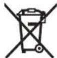
Do not dispose of power tools and batteries/re-chargeable batteries into household waste!
Only for EU countries:
According to the Directive 2012/19/EU on waste electrical and electronic equipment and its transposition into national law, power tools that are no longer usable, and, according to the Directive 2006/66/EC, defective or drained batteries must be collected separately and disposed of in an environmentally correct manner.
If disposed incorrectly, waste electrical and electronic equipment may have harmful effects on the environment and human health, due to the potential presence of hazardous substances.
Only for United Kingdom:
According to The Waste Electrical and Electronic Equipment Regulations 2013 (SI 2013/3113) (as amended) and the Waste Batteries and Accumulators Regulations 2009
(SI 2009/890) (as amended), products that are no longer usable must be collected separately and disposed of in an environmentally friendly manner.
Battery packs/batteries:
Li-ion:
Please observe the notes in the section on transport (see "Transport", page 40).
Transport
Robert Bosch Calle No. 405
C.P. 50071 Zona Industrial, Toluca - Estado de Mexico
Tel.: (52) 55 528430-62
Tel.: 8006271286
www.bosch-pt.com/serviceaddresses
Transport
www.bosch-pt.com/serviceaddresses
Transport
www.bosch-pt.com/serviceaddresses
Transport
Stationary or flexible mounting
www.bosch-pt.com/serviceaddresses
Transport
Bosch Service Center
Telegrafovj 3
2750 Ballerup
At www.bosch-pt.dk you can order spare parts online or create a repair order.
Service Center phone: 44898855
Fax: 44898755
E-mail: vaerktoej@dk.bosch.com
www.bosch-pt.com/serviceaddresses
Transport
Bosch Service Center
Telegravej 3
2750 Ballerup
Denmark
Tel.: (08) 7501820 (within Sweden)
Fax: (011) 187691
You can find more contact information for service here:
www.bosch-pt.com/serviceaddresses
Transport
The recommended lithium-ion batteries are subject to the requirements for dangerous goods. The user can transport the batteries by road without further obligations.
(13) Drilling holes for mounting
(14) Insert plate
(15) Locking clamp
(16) Locking cap for selecting miter angle (horizontal)
(34) Transport safety device
www.bosch-pt.com/serviceaddresses
Transport
www.bosch-pt.com/serviceaddresses
Transport
Before using the electric tool, it must be securely mounted on a stable and level surface (e.g., a workbench).
Mounting on a work surface (see figures B1-B2)
Mounting on a Bosch workbench
The Bosch workbenches provide the electric tool with a secure grip on any surface thanks to their non-slip feet. The feet of the workbench are inserted into the corresponding recesses.
Read the safety instructions and assembly instructions for the workbench. Make sure that the safety instructions and assembly instructions have been followed to avoid electric shock, fire and/or serious injuries. Mount the electric tool on the workbench. The workbench ensures that the tool is stable and reduces the risk of tipping over. The electric tool must be mounted on the workbench when it is in the transport position.
Mounting position (6 components) (see figure B3)
If, in exceptional circumstances, it is not possible to mount the electric tool on a level and stable work surface, you can secure it with the anti-tip protection.
Without the anti-tip protection, the electric tool is not stable and can tip over, especially during operation, with the saw blade rotating and/or cutting. - Adjust or remove the anti-tip protection (18) so that the electric tool is level on the work surface.
Dust extraction/chip extraction
Dust from materials such as lead-containing paint, some types of wood, minerals and metals can be harmful. Contact with or inhalation of dust can cause allergic reactions and/or respiratory diseases in the user or bystanders.
Certain types of dust, e.g., oak or beech dust, are considered carcinogenic, especially when combined with additives for wood treatment (chromate wood preservatives). Such materials may only be processed by specially trained personnel.
Checking (see figure T1)
- Place the workpiece on the cutting line. - Guide the tool arm (7) slowly downwards. - Push the workpiece until the saw blade aligns with the cutting line. - Hold the workpiece firmly and guide the tool arm slowly upwards. - Allow the workpiece to cool. - Activate the laser with the switch (6), without pressing the laser activation button (5).
The laser lines must be at the same distance from the cutting line on both the left and right sides.
on the workpiece, especially when the tool arm is guided downwards.
Protective cap of the charging unit (see figure T2)
Remove the two screws (55) of the protective cap of the charging unit and remove the protective cap.
www.bosch-pt.com/serviceaddresses
Transport
The contained lithium-ion batteries are subject to the Dangerous Goods Legislation requirements. The user can transport the battery by road without further requirements.
When transport is carried out by third parties (e.g. air transport or forwarding agency), special requirements on packaging and labelling must be complied with. For the preparation of the item being shipped, consulting an expert for hazardous material is required.
Only dispatch the battery if the housing is undamaged. Tape open contacts and pack up the battery so that it cannot move around in the packaging. Please also observe possibly more detailed national regulations.
Disposal

www.bosch-pt.com/serviceaddresses
188 | Polski
Nakliye
Robert Bosch Sp. z o.o.
www.bosch-pt.com/serviceaddresses
Transport
Bosch Service Center PT
K Vapence 1621/16
692 01 Mikulov
You can order the repair of your machine or spare parts online at www.bosch-pt.cz.
www.bosch-pt.com/serviceaddresses
Transport
Recommended lithium-ion batteries are subject to the requirements of the law on dangerous goods. These batteries can be transported by the user by road without further conditions.
www.bosch-pt.com/serviceaddresses
Transport
Recommended lithium-ion batteries are subject to the requirements for the transport of dangerous goods. These batteries may be transported by the user by road without further measures.
When sending by third parties (e.g., by air freight or through a forwarding agent), the specific requirements for packaging and labeling must be observed. In such cases, consultation with a dangerous goods transport expert is absolutely necessary when preparing the shipment.
Only send batteries if their packaging is not damaged. Cover open contacts and pack the battery so that it cannot move around in the packaging. Also observe any additional national regulations.
Disposal

www.bosch-pt.com/serviceaddresses
Transport
Transportation
Categorical rejection is not allowed. Other mechanical impacts on packaging during transportation - during unloading/loading, it is not allowed to use any kind of equipment operating on the principle of gripping the packaging. For detailed requirements for transportation conditions, see GOST 15150-69 (Condition 5). Transport at ambient temperatures from -50°C to +50°C. Relative humidity of air must not exceed 100%.
Safety instructions
General safety instructions for power tools
WARNING
Read all safety instructions, instructions, illustrations and specifications provided with this power tool. Failure to follow any of the instructions listed below may result in electric shock, fire and/or serious injury.
Save these instructions and warnings for future use.
The term "power tool" used in these instructions and warnings refers to power tools operated from the mains (with a power cord) and battery-operated power tools (without a power cord).
Workplace safety
Keep your workplace clean and well lit. Cluttered or dark areas can lead to accidents. Do not operate power tools in explosive atmospheres, e.g., in the presence of flammable liquids, flammable gases or dust. Power tools create sparks, which may ignite dust or fumes. While working with a power tool, do not allow bystanders near your workplace. Distraction can cause you to lose control of the power tool. The equipment is intended for use in household conditions, commercial areas and public places, industrial areas with low power consumption, without exposure to harmful and hazardous production factors. The equipment is intended for operation without constant presence of service personnel.
Electrical safety
Safety
The power tool plug must match the power outlet. Never modify the plug in any way. Do not use any adapter plugs with earthed (grounded) power tools. Unmodified plugs and matching outlets will reduce risk of electric shock. Avoid body contact with earthed or grounded surfaces, such as pipes, radiators, ranges and refrigerators. There is an increased risk of electric shock if your body is earthed or grounded. Protect the power tool from moisture. Water entering a power tool will increase the risk of electric shock. Do not abuse the cord. Never use the cord for carrying, pulling or unplugging the power tool. Keep cord away from heat, oil, sharp edges or moving parts. Damaged or entangled cords increase the risk of electric shock. When operating a power tool outdoors, use an extension cord suitable for outdoor use. Use of a cord suitable for outdoor use reduces the risk of electric shock. If operating a power tool in a damp location is unavoidable, connect the power tool to a supply protected by a residual current device (RCD). Use of an RCD reduces the risk of electric shock.
Personal Safety
Stay alert, watch what you are doing and use common sense when operating a power tool. Do not use a power tool while you are tired or under the influence of drugs, alcohol or medication. A moment of inattention while operating power tools may result in serious personal injury. Use personal protective equipment. Always wear eye protection. Protective equipment such as dust mask, non-skid safety shoes, hard hat, or hearing protection used for appropriate conditions will reduce personal injuries. Prevent unintentional starting. Ensure the switch is in the off-position before connecting to power source and/or battery pack, picking up or carrying the tool. Carrying power tools with your finger on the switch or energising power tools that have the switch on invites accidents.
Connecting a power tool to a wall outlet with the switch on can lead to accidents.
Install the tool and the key switch to turn on the power tool. The tool for the key, which is located on the rotating parts of the power tool, can lead to injury. Do not assume an unnatural body position. Always maintain a stable position and balance. This allows you to better control the power tool in unexpected situations. Wear suitable work clothing. Do not wear loose clothing or jewelry. Keep your hair away from moving parts. Loose clothing, jewelry, or long hair can get caught in rotating parts. If dust extraction and collection equipment can be installed, check the connection and proper use. Using a dust extractor can reduce the risk posed by dust. Good knowledge of power tools, gained through frequent use, should not lead to overconfidence and ignoring the safety rules for handling power tools. One careless act within a fraction of a second can lead to serious injury. ATTENTION! In the event of a power tool malfunction due to a full or empty battery, or interruption of power supply, or damage to the control unit, set the switch to the off position, making sure it is not locked (if present). Disconnect the plug from the socket and remove the battery pack. This prevents uncontrolled restart. Qualified personnel in accordance with this manual means persons who are familiar with the assembly, installation, commissioning, and maintenance of the power tool. Persons at least 18 years old who have studied the technical description, operating instructions, and safety rules are allowed to work with the power tool. The product is not intended for use by persons (including children) with reduced physical, sensory, or mental capabilities, or lack of experience and knowledge, unless they are under supervision or have been instructed in the use of the power tool by a person responsible for their safety.
Use of the power tool and handling it
Do not overload the power tool. Use the correct power tool for your application. The correct power tool will do the job better and more safely at the rate for which it was designed.
When working with a power tool, keep the switch in the off position. A power tool that cannot be turned on or off is dangerous and must be repaired. Before adjusting the power tool, changing accessories, or storing the power tool, disconnect the plug from the power source and/or remove the battery pack, if possible. This precaution prevents accidental starting of the power tool. Store power tools out of the reach of children. Do not allow persons who are unfamiliar with the power tool or who have not read these instructions to operate it. Power tools are dangerous in the hands of untrained users. Maintain power tools and accessories carefully. Check for misalignment or binding of moving parts, breakage of parts, and any other condition that may affect the operation of the power tool. If damaged, have the power tool repaired before use. Many accidents are caused by poorly maintained power tools. Keep cutting tools sharp and clean. Properly maintained cutting tools with sharp cutting edges are less likely to bind and are easier to control. Use the power tool, accessories, and tool bits, etc., in accordance with these instructions, taking into account the working conditions and the work to be performed. Use of the power tool for operations different from those intended could result in a hazardous situation. Keep handles and grasping surfaces dry, clean, and free from oil and grease. Slippery handles and grasping surfaces do not allow for safe handling and control of the tool in unexpected situations.
Use and care of battery-powered tools
Recharge the battery packs only with the chargers specified by the manufacturer. A charger that is suitable for one type of battery pack may create a risk of fire when used with another battery pack. Use the power tools only with the battery packs specifically designed for them. Use of any other battery packs may create a risk of injury and fire. When the battery pack is not in use, keep it away from other metal objects, like paper clips, coins, keys, nails, screws,
or other small metal objects that can make a connection from one terminal to another. Shorting the battery terminals together may cause burns or a fire.
The battery fluid can be hazardous. Avoid contact with it. In case of accidental contact, rinse with water. If this fluid gets into the eyes, additionally consult a doctor. Leaking battery fluid can cause skin irritation or burns. Do not use damaged or modified batteries or tools. Damaged or modified batteries may behave unpredictably, which can lead to fire, explosion, or risk of injury. Do not place the battery or tool in fire or expose them to high temperatures. Fire or temperatures above 130°C may cause explosion. Follow all charging instructions and do not charge the battery or tool at temperatures outside the range specified in the instructions. Incorrect charging or charging at temperatures outside the specified range may damage the battery and increase the risk of fire.
Service
Repair of the power tool must be carried out only by qualified personnel and only with original spare parts. This ensures the safety of the power tool. Never service damaged batteries. Servicing batteries is allowed only by the manufacturer or an authorized service organization.
Safety instructions for reciprocating saws
Reciprocating saws are intended for cutting wood or wood-like materials. Their use with abrasive cutting discs for cutting ferrous metals, e.g., bars, rods, pipes, etc., is prohibited. This can lead to jamming of the moving parts, e.g., the lower protective guard. Sparks generated during abrasive cutting may penetrate the lower protective guard, the insert in the cutting slot, and plastic parts. Whenever possible, use clamps to secure the workpiece. If you hold the workpiece by hand, you must keep your hands at a distance of at least 100 mm from either side of the saw blade. Do not use this saw to cut workpieces that are too small to be securely clamped or held by hand. If the distance is too close...
...the saw blade may come into contact with the workpiece, causing injury.
The workpiece must be held stationary and clamped with the hand supported simultaneously on the guard and the table. Never feed the workpiece with the blade and never perform cutting on the fly. Unclamped or protruding workpieces can be thrown at high speed, which can cause injury. Push the blade through the workpiece. Do not push the blade through the workpiece towards yourself. To make a cut, lower the blade head and move it over the workpiece without cutting, start the motor, press the blade head down and push the blade through the workpiece. Cutting with a pulling motion towards yourself will most likely cause the blade to climb onto the workpiece and be violently thrown in the direction of the operator. The hand must never cross the intended cutting line, neither in front nor behind the blade. Holding the workpiece with crossed hands, i.e., holding the workpiece with the right hand to the left of the blade or vice versa, is very dangerous. Do not place your hand behind the guard closer than 100 mm from either side of the blade, nor for removing wood chips, nor for anything else while the blade is still rotating. The speed of the rotating blade can be underestimated, which can lead to serious injury. Inspect the workpiece before cutting. If the workpiece has a bent or curved shape, clamp it with the outer surface of the bend against the guard. Always ensure that there is no gap between the workpiece, the guard, and the table along the cutting line. Bent or curved workpieces can twist or shift, which can cause the rotating blade to jam during cutting. The workpiece must not contain nails or foreign objects. Use the saw only after the table is cleared of tools, wood scraps, etc., except for the workpiece. Small debris, wood pieces, or other objects that come into contact with the rotating blade can be thrown at high speed. Cut the workpieces only one at a time. Stacked workpieces cannot be properly clamped or secured, so they may be caught by the blade or shift during cutting.
Before use, make sure the miter saw is mounted and installed on a level, stable work surface. The saw must be secured to the work surface. Plan your work. Each time you change the cutting angle (bevel or miter), make sure the adjustable fence is correctly set to support the workpiece and will not interfere with the blade or the guard system. Do not turn on the power tool and do not place the workpiece on the table until the blade guard is fully checked along the imaginary cut line to ensure there are no obstructions or danger of cutting the guard. Provide adequate support, e.g., extension tables, saw horses, etc., for workpieces that are larger than the table of the miter saw. If the workpiece is longer or wider than the table, without proper support it may tip over. If the cut-off piece or the workpiece tips over, it can lift the lower guard or be thrown by the rotating blade. Do not use other tools as auxiliary supports. An unstable workpiece can cause the blade to bind or the workpiece to shift during cutting, which could pull your hands into the blade. The cut-off piece must not be jammed or pressed against the rotating blade. If the workpiece binds, i.e., when using the cutting head, the workpiece can jam and the blade can be thrown back violently. Always use a clamp or a vise designed to securely hold round materials such as rods or tubes. Rods tend to roll, causing the blade to "bite" and pull the workpiece with your hand into the blade. Let the blade reach full speed before touching the workpiece. This reduces the risk of the workpiece being thrown. If the workpiece or the blade gets caught, turn off the miter saw. Wait until all moving parts have stopped, then unplug the tool from the power outlet and/or remove the battery. Then free the jammed material. Continuing to cut a jammed workpiece can cause loss of control or damage to the miter saw.
After completing the cut, release the switch, lower the saw head and wait until the saw blade has come to a complete stop, then remove the cut piece. Touching the saw blade by hand is dangerous. Hold the handle firmly, make the complete cut and do not release the switch until the saw head has fully lowered. When the saw head is lowered, it may suddenly jerk downwards, which can lead to a risk of injury. Do not release the handle when the saw head is at its lowest position. Always return the saw head to the upper position manually. Uncontrolled movement of the saw head can lead to injury. Keep your work area clean. Mixtures of materials are especially dangerous. Dust from light metals can ignite or explode. Do not use blunt, cracked, bent, or damaged saw blades. Saw blades with blunt or incorrectly set teeth result in a very narrow kerf, leading to increased friction, jamming of the blade, and kickback. Do not use saw blades made of high-alloy high-speed steel (HSS steel). Such blades can easily break. Always use saw blades of the correct size and with a suitable mounting hole (e.g., diamond-shaped or round). Saw blades that do not match the mounting parts of the saw run eccentrically and lead to loss of control over the power tool. Never remove cut-off material, chips, etc. from the cutting area while the power tool is running. First bring the power tool to a standstill and then switch it off. Do not touch the saw blade after work until it has cooled down. The saw blade gets very hot during work. If the battery is damaged or used improperly, liquid may leak out. The battery may ignite or explode. Ensure fresh air supply and consult a doctor if complaints arise. Gases can irritate the respiratory tract. Do not open the battery. There is a risk of short circuit. Protect the battery from sharp objects, e.g., nails or screwdrivers, as well as from external force impacts. This can lead to an internal short circuit, fire, explosion, or overloading of the battery.
Use the battery only in products from the manufacturer. Only in this way is the battery protected against dangerous overload.

Protect the battery from high temperatures, e.g., from intense sunlight, fire, dirt, water, and moisture. There is a risk of explosion and short circuit.
The power tool is delivered with a laser radiation warning label (see table "Symbols and their meanings"). If the text on the laser radiation warning label is not in your national language, before the first start-up, cover it with the label in your national language that is included in the scope of delivery. Never make the warning labels on the power tool unrecognizable.

This path can be dangerous for the life of animals, and do not look at the laser beam directly. This path can be dangerous for the life of animals, and do not look at the laser beam directly.
In case of laser beam hitting the eye, it is necessary to deliberately close the eyes and immediately turn away from the beam. Do not change anything in the laser device. The possibilities described in this manual for adjustment are not associated with risks. Do not allow children to use the power tool without supervision. Children may, due to carelessness, blind themselves or others.
Symbols
The following symbols may have meaning for the user of the power tool. Please remember these symbols and their meanings. Correct interpretation of the symbols will help you work better and more safely with this power tool.
Symbols and their meaning
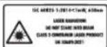
Laser radiation. Avoid direct eye contact with the laser beam. Class 2 laser device for the general consumer market EN 50689:2021

Do not put your hands in the area of the saw blade or in the working power tool. When in contact with the saw blade, there is a risk of injury.
Symbols and their meaning

Wear a dust respirator.

Wear safety glasses.

Wear hearing protection. Noise exposure can lead to hearing loss.

Dangerous area! If possible, keep hands, fingers, and arms away from this area.
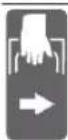
When transporting the power tool, hold it only by these designated places (recesses for gripping) or by the handle for carrying.
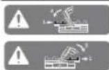
When tilting the saw to a vertical angle, the adjustable support plates must be extended outward or removed altogether.
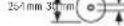
Check the dimensions of the disc. The diameter of the mounting hole must match the spindle of the tool. If necessary, use a reducing adapter to ensure that the adapter dimensions match the thickness of the disc body and the diameter of the mounting hole of the disc, as well as the spindle diameter of the tool. If possible, use the reducing adapters supplied with the disc.
3601M511B. 3601M5118.
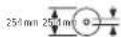
The disc diameter must match the data on the label.
Product and service description

Read all safety instructions and instructions. Failure to follow the safety instructions and instructions may result in electric shock, fire, and/or serious injury.
Please observe the illustrations at the beginning of the operating instructions.
Intended use
The power tool is intended for cutting and rough grinding of wood. It is possible to make horizontal cuts at an angle from -48° to +48°, as well as vertical cuts at an angle from 47° (left) to 47° (right).
The power of the power tool is designed for cutting hard wood, as well as wood-based materials.
When using appropriate discs, it is possible to cut aluminum profiles and plastic.
This product is classified as a consumer laser product in accordance with EN 50689.
Illustrated components
The numbering of the components refers to the illustration of the power tool on the page with the illustration.
(1) Locking screw for the pendulum guard (2) Feed mechanism (3) Carrying handle (4) Protective cover (5) Lock-off button (6) On/off switch (7) Handle (8) Protective cap for laser (9) Opening for laser beam exit (10) Pendulum guard (11) Roller guide (12) Saw table (13) Mounting holes (14) (15) Clamping lever (16) Adjustable stop for miter angle (miter angle) (17) Handle for preselecting miter angle (horizontal) (18) Anti-tip device (19) Warning label for laser radiation (20) Scale for most common angles (horizontal) (21) Miter angle scale (horizontal) (22) Clamping screw for table extension (23) Table extension (24) Support for workpiece (universal mounting) (25) Fixed stop (26) Adjustable stop (27) Bevel angle scale (vertical)
248|Russian
(28) Ykaataenb yra pacnna (vertical) (29) DeΦηκTQP ctpyKKn (30) NnIbHoe nOIOTHO (31) FmKcaTOp WnHdEa (32) KhoNka pa36noknpOBKn aKKymyIaTopa (33) AkkymyIaTOp (34) TpaHcnopTbI npedoxpAHntenb (35) Cko6a npedoxpahntenr OtonpokndbBaHn (36) PpOdoJIbHbIy npOp (37) NbIeNc6OpHbM MeWOK (38) HcnpoBOHbBnHTOrpaHnHTeIgny6HB (39) OrpaHnHTeIb rny6HbI (40) BnHT cTpy6uHbI (41) Ctpy6uHa (42) OTBepCTnIaI CTpy6uH (43) KIOU C BHTpeHHHm WeecTnRpaHHNKOM/LJInueBaOTBepTKa (44) Φικυμην BHT perγιρεόη μγορόη πλακή (45) 3aXHHoE KOeCo dYrna CKOca (BepTKaJIbHO- ro)
(46) ΦИКСИРУЮПЕ N pbluA rДЯугla cKOca (BepTnKaJIb-Horo) (47) NpTPOH OONOpBdIa3arOToBKN (Ha 3neKTPoHHCTpy-MeHTe) (48) IarpoH BtopoH onOpbI dIa 3arotOBKn (Ha onope dIra 3arotOBKn) (49) BoNTcpe3b6oB (50) AaanTep nbIeyndaenHn (51) BnHT C BYHTpeHHm uectHrpahHKOM dny Kpen- neHn HnBHO DnCKa (52) PnKHMHoi fnaHeu (53) BHyTpEnHH 3aXnMHOfnaHe (54) Kpenexxhble BHTbI DnB CtABHO nnaCTHbI (55) BnHT 3aunTHoro KOnnaUka na3epa (56) KpenexKbHbBnHT nJa Kopnyca naepa (57) Kopnyc na3epa (58) Yka3aTeB yrrna pacnna (rotnphtalbHoro) (59) BnHT yka3aTeIy rna pacnHa (ropH0rTaIbHorO) (60) BnHT yka3aTey rya pacnna (BepTKKanbHorO) (61) Yny6neHnIa3xAbaTa
Technical data
Cordless drill driver GCM 18V-254 D GCM 18V-254D
Drill hole diameter 3025.4
A) Measured at 20-25°C with ProCORE18V 8.0Ah battery.
B) Depending on the battery pack used
C) Limited power at temperatures < 0°C
Values may vary depending on the tool, application, and environmental conditions. More detailed information is available at www.bosch-professional.com/wac.
Permissible workpiece dimensions (maximum/minimum): (see "Permissible workpiece dimensions", page 255)
Noise data
Noise emission values determined according to EN IEC 62841-3-9.
A-weighted sound pressure level typically: sound pressure level 97 dB(A); sound power level 106 dB(A). Uncertainty K = 3 dB.
Use hearing protection!
The noise emission value given in these instructions has been measured in accordance with the standard measuring method and may be used for comparing power tools. It is also suitable for a preliminary assessment of noise emission.
The vibration emission value may differ if the power tool is used for other applications with different accessories or if it is not maintained properly. This can significantly increase the vibration emission over the total working period.
For an accurate estimation of vibration exposure over a defined time interval, you must also consider the times when the tool is switched off or running but not actually in use. This can significantly reduce the vibration exposure over the total working period.
Battery
You can purchase cordless power tools from Bosch even without a battery. The packaging indicates whether the battery is included in the delivery of your power tool.
Charging the battery
Use only the chargers listed in the technical specifications. Only these chargers are matched to the lithium-ion battery of your power tool.
Note: According to international transport regulations, lithium-ion batteries are supplied partially charged. To ensure maximum battery capacity, fully charge the battery before first use.
Installing the battery
Insert the charged battery into the battery compartment until it clicks into place.
Removing the battery
To remove the battery, press the battery release button and pull the battery out. Do not use force.
The battery is equipped with two locking stages to prevent the battery from falling out when the release button is pressed accidentally. As long as the battery is inserted in the power tool, keep it in the locked position.
Battery charge indicator
Note: Not all battery types are equipped with a charge indicator.
The green LEDs on the battery charge indicator show the charge level. For safety reasons, the charge indicator is only active when the power tool is at a standstill.
Press the battery charge indicator button to display the charge level of the battery. This is also possible when the battery is removed.
If after pressing the battery charge indicator button the battery charge indicator does not light up or the light indicator, the battery is defective and must be replaced.
Battery GBA 18V...

Luminous intensity
| HenpepbHbCBeT 3zeHebIX cBetoNoIOB | 60-100% |
| HenpepbHbCBeT 2zeHebIX cBetoNoIOB | 30-60% |
| HenpepbHbBcBET 13eHoro CBETOHOJa | 5-30% |
| Mirahoшni CBET 1Зеленого CBETOДноа | 0-5% |
Battery ProCORE18V...

| СbvToDnOД EmKoCTb | |
| HenpepbIbHbI CBET 5 3eIeHbIX CBToDnODoB | 80-100 % |
| HenpepbIbHbI CBET 4 3eIeHbIX CBToDnODoB | 60-80 % |
| HenpepbIbHbI CBET 3 3eIeHbIX CBToDnODoB | 40-60 % |
| HenpepbIbHbI CBET 2 3eIeHbIX CBToDnODoB | 20-40 % |
| HenpepbIbHbI CBET 1 3eIeHoro CBToDnOda | 5-20 % |
| MiraIoUssI CBET 1 3eIeHoro CBToDnOda | 0-5 % |
Instructions for optimal handling of the battery
Protect the battery from moisture and water.
Store the battery only in the temperature range of -20°C to 50°C. Do not leave the battery in the car in summer.
From time to time, clean the ventilation slots of the battery with a soft, dry brush.
A significant reduction in operating time after charging indicates that the battery is aging and must be replaced.
Follow the disposal instructions.
Assembly
Before starting work on the tool, changing tools, etc., as well as during transport and storage, remove the battery from the power tool. There is a risk of injury if the tool is switched on unintentionally.
Scope of delivery

Note the description of the scope of delivery at the beginning of the operating instructions.
Before using the power tool, check for the presence of all the components listed below:
- Panel saw with installed saw blade - Locking knob (45) - Adjustable parallel guide (26) - Clamp (41) - Hex key/Phillips screwdriver (43) - Dust bag (37) - Workpiece supports (24) (2 pcs.)
Note: Check the power tool for possible damage.
Before using the power tool, carefully check the protective devices or components for possible damage. Check for flawless function, free movement, and integrity of the moving parts. All parts must be correctly installed and fulfill all conditions to ensure flawless operation.
Damaged protective devices and components must be repaired by qualified personnel at an authorized specialized workshop or replaced.
Assembly of individual parts
- Carefully unpack all supplied parts. Remove all packaging material from the power tool and supplied accessories. To ensure safe operation, before assembling the kit components, make sure the power tool is in transport condition.
Installing the workpiece supports (see Fig. A1)
The workpiece supports (24) can be installed on the left, right, or in the middle of the power tool. The universal adjustment system provides multiple adjustment options and expands the working area (see Fig. G).
If necessary, insert the workpiece support (24) into the mounting holes (47) on the power tool or into the mounting holes (48) of the second workpiece support. Do not carry the power tool by the workpiece supports.
When transporting the power tool, use only the transport devices.
Installing the locking knob (see Fig. A2)
The locking knob (45) serves to fix the vertically adjusted miter angle and is necessary for safe operation.
Unscrew the locking knob (45) from the threaded rod (49). Slide the locking knob (45) clockwise onto the threaded rod (49) and tighten it.
Installing the adjustable parallel guide (see Fig. A3)
Tighten the adjusting screw (26) before starting work. -Turn the adjusting screw (26) to the right of the disc according to the specified direction and tighten the locking screw (44).
The adjusting part of the plate must be aligned with the saw blade.
Stationary or temporary stand
For long-term work, the power tool must be mounted on a flat, stable work surface (e.g., workbench).
Mounting on a work surface (see Fig. B1-B2)
-Secure the power tool with suitable screws to the work surface. For this purpose, use the holes (13).
HNN
-Clamp the power tool with standard clamps to the work surface.
Mounting on a Bosch production table
The Bosch production table allows the power tool to be positioned at any angle and adjusted in height with the crank. The table serves as a support for long workpieces.
Read all safety warnings and instructions supplied with the table. Failure to follow the warnings and instructions may result in electric shock, fire, and/or serious injury. Properly set up the table before mounting the power tool. Correct assembly of the table is important to prevent tipping. -Mount the power tool on the table in the transport position.
Anti-tip device (recommended!) (see Fig. B3)
If, as an exception, it is impossible to place the power tool on a flat, stable surface, the anti-tip device can be used.
Without the anti-tip device, the power tool is unstable, especially when cutting at maximum horizontal and/or vertical angles, and may tip over. Screw in or out the anti-tip device (18) so that the power tool stands firmly on the work surface.
Dust and chip removal
For some materials, such as paints, coatings containing lead, some types of wood, minerals and metals, it may be harmful to health.
Contact with dust and inhalation of dust into the respiratory tract may cause allergic reactions and/or damage to the motor pathways of the operator or persons nearby.
Certain dusts, e.g., oak and beech dust, are considered carcinogenic, especially in combination with additives for wood treatment (chromate, wood preservative). Material containing asbestos may only be processed by specialists.
- If possible, use a suitable material extraction system. - Ensure good ventilation of the work area.
- It is recommended to use a respirator mask with filter class P2. Follow the regulations applicable in your country for the materials being processed. Avoid dust accumulation at the workplace. Dust can easily ignite.
Dust/chip removal may be blocked due to dust, chips, and detached workpiece fragments.
- Switch off the power tool and remove the battery. - Wait until the dust disk has come to a complete stop. - Find the cause of the blockage and eliminate it.
Integrated dust extraction system (see Fig. C)
For simple collection, use the inlet with the dust collection bag (37).
- Set the transport handle (3) vertically. Insert the dust collection bag (37) into the dust outlet (50) and turn the bag so that the dust bag connector locks into the opening on the adapter.
During work, the dust collection bag must never come into contact with rotating parts of the power tool.
Empty the dust collection bag in a timely manner.
Check and clean the dust collection bag after each use. To avoid the risk of fire, remove the dust bag when vacuuming aluminum.
External dust extraction
The dust extraction adapter (50) can be connected to a suitable vacuum cleaner (35 mm). - Connect the vacuum hose to the dust extraction adapter (50).
Use only sharp saw blades.
Use special saw blades intended for cutting wood and materials similar to wood.
Replacing the saw blade (see figures D1-D4)
Before any work on the power tool, pull the plug out of the socket. When switching on inadvertently, there is danger of injury. When installing the saw blade, wear protective gloves. Contact with the saw blade can lead to injury.
Use only saw blades with a maximum permissible speed higher than the no-load speed of your power tool.
252|Russian
Use only saw blades with parameters specified in this operating manual that comply with EN 847-1 and have the corresponding marking.
Use only saw blades recommended by the power tool manufacturer and suitable for the material to be processed. This prevents overheating of the teeth and clogging.
Removing the saw blade
- Place the power tool in the working position. - Swivel the protective guard (10) back and hold it in this position. - Turn the screw with internal hexagon (51) using the hex key (6 mm) (43) and simultaneously press the spindle lock (31) until it engages. - Keep the spindle lock (31) pressed and simultaneously turn the screw with internal hexagon (51) clockwise (left-hand thread!). - Remove the clamping flange (52). - Remove the saw blade (30). - Slowly swivel the protective guard back.
Mounting the saw blade
Make sure that the cutting direction of the teeth (arrow on the saw blade) matches the direction of the arrow on the protective guard!
If necessary, clean all parts to be mounted before mounting.
- Swivel the protective guard (10) back and hold it in this position. - Place the new saw blade on the inner clamping flange (53). - Mount the clamping flange (52) and screw in the screw with internal hexagon (51). Press the spindle lock (31) so that it engages, and then tighten the screw with internal hexagon counterclockwise. - Slowly swivel the protective guard back.
Working with the tool
Do maintenance work, tool changes, etc., as well as during transport and storage, remove the battery from the power tool. When switching on unexpectedly, there is a risk of injury.
Transport guard (see Fig. E)
The transport guard (34) protects the power tool during transport to different workplaces.
Removing the transport guard (working position)
- Press the bracket (7) slightly down to relieve the load on the transport guard (34). - Pull the transport guard (34) completely out. - Carefully lower the bracket to the working position of the tool.
Activating the transport guard (transport position)
Release the locking button (1) if the tool (2) is tilted. Then lower the bracket to the working position of the tool completely down and lock the locking button again to secure the tool. - Pull the guide tubes (39) up. - Lock the table (12) with the locking handle (16). - Turn the bracket to the working position of the tool by the handle (7) down until the transport guard (34) can be fully inserted.
The bracket of the power tool is securely locked in the transport position.
Preparation for operation
For accurate cutting after intensive work, check the basic settings of the power tool and adjust if necessary.
The tool must be sharp and clean.
The service workshop will perform the repair work quickly and reliably.
Extending/expanding the saw table (see Fig. F-G)
Long and heavy workpieces must be supported or placed on something underneath.
The table can be extended to the left and right with the extension elements (23).
- Loosen the locking screw (22). - Pull the stop (23) outward to the required length. - To fix the stop, tighten the locking screw (22) again.
The universal system for repositioning the stops for workpieces (24) provides a variety of options for extending and expanding the working area.
- If necessary, install the stop for workpieces (24) in the bracket (47) on the power tool or in the bracket (48) of the second stop for workpieces. Do not carry the power tool by the stops for workpieces. When transporting the power tool, use only the transport devices.
Adjusting the stop plate (see fig. H)
When working with horizontal and/or vertical bevel angles, depending on the cutting direction, the left or right adjustable stop plate (26) must be pulled out or completely removed.
Do not process workpieces whose dimensions are insufficient for clamping.
- Firmly press the workpiece against the stop plates (26) (25). Insert the supplied clamp (41) into one of the holes (42) provided for it. - Adjust the threaded rod (40) of the clamp to the height of the workpiece. - Tighten the threaded rod (40) firmly, thus clamping the workpiece.
Setting the horizontal miter angle
Setting the standard horizontal miter angle (see fig. J)
For quick setting of frequently used horizontal miter angles on the miter table, notches (20) are provided:
Left Right
0°
45°; 30°; 22.5°; 15° 15°; 22.5°; 30°; 45°
- Release the locking handle (16) if it is tightened. - Pull the lever (17) and turn the miter table (12) to the desired notch to the left or right. - Release the lever. The lever must engage in the notch. - Tighten the locking handle (16) again.
Setting an arbitrary horizontal miter angle (see fig. K)
The top bevel angle can be adjusted in the range from 0° (left) to 48° (right).
- Release the locking knob (16) if the range is too tight. - Pull the lever (17) while simultaneously pressing the locking button (15) so that it engages in the intended slot. This ensures free movement of the saw head.
-Turn the saw head (12) and the locking knob to the right so that the bevel angle indicator (58) points to the desired bevel angle. -Tighten the locking knob (16). -To release the lever (17) again (for adjusting standard horizontal bevel angles), pull it upward.
The locking button (15) returns to its original position, and the lever (17) can be engaged again in the notches (20).
Permissible workpiece dimensions
Maximum workpieces:
| Topsuzhontalbnyyrol pachnila | Beptrukalbnyyrol pachnila | Blycota x shpiha[MM] |
| 0° 0° 90x305 | ||
| 45° (cnpaba/cne-ba) | 0° 90x215 | |
| 45° (cneba) 45° (cneba) 55x215 | ||
| 45° (cnpaba) 45° (cnpaba) 30x215 | ||
| 0° 45° (cneba) 55x305 | ||
| 0° 45° (cnpaba) 30x305 | ||
Minimum workpieces (= all workpieces that can be clamped on the left or right of the saw blade using the supplied clamp (41)): 100 x 40 mm (length x width)
Max cutting depth at 0°/0°: 90 mm
Setting the stop for cutting a groove (see fig. Q)
To increase the groove depth, the depth stop must be adjusted.
-Turn the depth stop (39) forward. - Set the saw unit with the handle (7) to the lower position. -Adjust the adjusting screw (38) so that its end touches the depth stop (39). - Carefully raise the saw unit.
Cutting workpieces of the same length (see fig. R)
For simple cutting of workpieces of the same length, the longitudinal stop (36) can be used.
-Pull the longitudinal stop (36) upward. -Adjust the extension element of the stop (23) according to the desired workpiece length.
Special workpieces
Sharp edges of workpieces must be deburred to prevent injuries.
When starting the cut, do not allow the workpiece to jam between the blade and the rip fence. If necessary, use a special clamp.
Replacing the insert plate (see Fig. 8)
After prolonged use of the power tool, the insert plate (14) may become worn.
Replace the worn insert plate.
- Switch the power tool to the working position. - Loosen screws (54) with a standard Phillips screwdriver and remove the old insert plate (14). - Insert the new insert plate and tighten screws (54) again.
Adjusting the laser
Note: To check the laser function, the power tool must be disconnected from the power supply.
When adjusting the laser (e.g., when replacing the battery), never press the switch. Unintentional starting of the power tool can cause injury. - Switch the power tool to the working position. - Turn the adjusting screw (12) until the laser line (20) is at 0°. The lever (17) must be engaged in the notch. To ensure an accurate cut after intensive use, check and, if necessary, readjust the laser beams. For this you will need a special tool. Our service workshop will perform this work quickly and reliably.
Control (see Fig. T1)
Mark the cutting line on the workpiece. - Slowly lower the tool head by the handle (7). - Align the workpiece so that the saw blade teeth are aligned with the cutting line. - Hold the workpiece in this position and slowly raise the tool head. - Clamp the workpiece. - Switch on the laser beams using the switch (6), without pressing the lock-off button (5).
The laser beams must be at the same distance from the marked cutting line on the workpiece along their entire length, both left and right, including during the initial phase and when moving the tool head down.
Removing the laser protective cap (see Fig. T2)
- Loosen the two screws (55) of the laser protective cap (8) with a hex key or a slotted screwdriver (43) and remove the laser protective cap.
Adjusting the lateral deviation when moving the tool head (see Fig. T3-T4)
- Tighten the locking screws (56) (approx. 1-2 turns). Do not unscrew the screws completely. Turn the laser housing (57) to the right or left so that when moving the tool, the laser beams do not deviate. Hold the laser housing (57) in this position and retighten the locking screws (56). Then secure the protective cap of the laser (8) again.
Basic settings - Check and correction
To ensure accurate operation, the initial settings of the power tool must be checked after intensive use and adjusted if necessary.
If you have experience and special tools, you can do this yourself.
The Bosch service workshop will perform this work quickly and reliably.
Checking the horizontal laser beam angle indicator (see figure U)
Place the power tool in the working position. Turn the turntable (12) to the 0° mark (20). The lever (17) must engage clearly in the notch.
Check
The laser beam angle indicator (58) must be aligned with the 0° mark on the scale (21).
Adjustment
Turn the screw (59) with a cross-head screwdriver to align the indicator to the 0° mark, then tighten the screw firmly.
Centering the vertical laser beam angle indicator (see figure V)
Loosen the clamping wheel (45). Press the stop lever (46) and use the tool to set the vertical angle to 0°. Release the stop lever (46). The stop lever must engage with a characteristic click. Retighten the clamping wheel (45).
Check
The laser beam angle indicator (28) must be aligned with the 0° mark on the scale (27).
HactpoKa
- Oтпустите винт (60) крестовой отверткой. Индикатор угла по отметке «0°» - плотно затяните винт.
Транспортировка электроинструмента (см. рис. W)
Перед началом работ по техобслуживанию, смене инструмента и т.д., а также при транспортировке и хранении извлекайте аккумулятор из электроинструмента. При непреднамеренном включении возникает опасность травмирования. Перед транспортировкой электроинструмента выполните следующее: - Отпустите фиксирующий винт (1), если он затянут. Потяните кронштейн рабочего инструмента до упора вверх и затяните фиксирующий винт. - Убедитесь в том, что ограничитель глубины (39) отведен назад до упора и не касается установочного винта (38) при перемещении кронштейна рабочего инструмента. - Приведите электроинструмент в транспортное положение. - Демонтируйте все принадлежности, которые не закреплены прочно на электроинструменте. Переносите неиспользуемые пильные диски по возможности в закрытом контейнере. - Установите ручку для транспортировки (3) вертикально. - Переносите электроинструмент за ручку для переноски (3) или за ручки захвата (61), расположенные по бокам пильного стола. Переносите электроинструмент, взявшись за транспортировочные приспособления, никогда не используйте для этих целей защитные устройства или упоры заготовок.
Техобслуживание и сервис
Техобслуживание и очистка
Перед началом работ по техобслуживанию, смене инструмента и т.д., а также при транспортировке и хранении извлекайте аккумулятор из электроинструмента. При непреднамеренном включении возникает опасность травмирования. Для обеспечения безопасной работы содержате электроинструмент и вентиляционные отверстия в чистоте.
Реализация продукции разрешается производить в магазинах, отделах (секциях), павильонах и киосках, обеспечивающих сохранность продукции, исключающих попадание на нее атмосферных осадков и воздействие источников повышенной температуры (резкого перепада температур), в том числе солнечных лучей.
Продавец (изготовитель) обязан предоставить покупателю необходимую достоверную информацию о продукции, обеспечивающую возможность ее правильного выбора. Информация о продукции в обязательном порядке должна содержать сведения, перечень которых установлен законодательством Российской Федерации.
Если при приобретении потребителем продукции была в употреблении или в ней установлен недостаток (недостатки), потребителю должна быть предоставлена информация об этом.
В процессе реализации продукции должны выполняться следующие требования безопасности:
- The seller must bring to the attention of the buyer the following information: the name of the organization, its location (address) and working hours; product samples in retail premises must provide the possibility for the buyer to familiarize themselves with the inscriptions on the products and exclude any independent actions of the buyer with the product that lead to its activation, except for visual inspection; the seller must bring to the attention of the buyer information about confirmation of compliance of these products with the established requirements, mandatory certificates or declarations of conformity; the sale of products is prohibited in the absence (loss) of their identification features, with an expired shelf life, as well as damaged batches without instructions (manual) for operation, a mandatory certificate of conformity or a mark of conformity.
The protective cover flaps must always move freely and close independently. Therefore, always keep the areas of the protective cover flaps clean.
After each use, remove dust and chips with a stream of compressed air or a brush.
Adjust the sliding roller (11).
Measures to reduce noise level
Measures provided by the manufacturer:
Smooth supply with special noise-reducing saw blades designed to reduce noise level
Measures taken by the operator:
- Mounting without vibration on a stable surface - Use of saw blades with properties that reduce noise level - Regular cleaning of the saw blade and power tool
Service and consultation on application issues
The service department will answer all your questions regarding repair and maintenance of your product, as well as spare parts. The exploded view and spare parts information can also be viewed at:
www.bosch-pt.com
The Bosch team of employees, providing consultations on the use of the product, will gladly answer all your questions regarding our product and its accessories.
Please, in all requests and orders for spare parts, be sure to indicate the 10-digit product number from the product nameplate.
www.bosch-pt.com/serviceaddresses
The buyer has the right to free warranty repair of the electric tool from the manufacturer's side during the warranty period, subject to the following conditions:
No mechanical damage;
No signs of violation of the operating manual requirements;
- The presence in the operating manual of the seller's mark of sale and the buyer's signature;
The serial number of the electric tool matches the serial number in the warranty card;
No traces of unauthorized repair.
The warranty does not cover:
Any damage caused by force majeure circumstances; normal wear and tear of the electric tool, as well as all electrical.
The warranty does not cover repairs, the need for which arises due to normal wear, reducing the service life of such parts and tools as connecting contacts, wires, brushes, etc.:
Natural wear (complete exhaustion of resource); equipment parts that fail due to incorrect installation, unqualified operation, incorrect use, violation of service and storage rules; malfunctions arising from overload of the electric tool. (Unconditional signs of tool overload include: change in the color of the working part, deformation or melting of parts and components of the electric tool, darkening or charring of the insulation of the electric motor wires under the influence of high temperature.)
Transportation
The recommended lithium-ion batteries are subject to the requirements for the transportation of dangerous goods. Batteries can be transported by the user themselves by car without the need to comply with additional standards.
When transporting with the involvement of third parties (e.g., courier services or transport companies), it is necessary to comply with special packaging and labeling requirements. In this case, when preparing the cargo for shipment, the participation of a dangerous goods expert is required.
Send the battery only with an undamaged housing. Seal the open contacts and pack the battery so that it does not move inside the packaging. Please also observe any possible additional national regulations.
Disposal

Power tools, batteries, accessories and packaging must be sorted for environmentally friendly recycling.
Do not dispose of power tools and batteries in household waste!
Only for EU member states:
In accordance with the European Directive 2012/19/EU on waste electrical and electronic equipment and its implementation in national law, power tools that are no longer usable must be collected separately and handed in for environmentally friendly recycling. In accordance with the European Directive 2006/66/EC, defective or exhausted batteries must be collected separately and handed in for environmentally friendly recycling.
Incorrect disposal of waste electrical and electronic equipment may have harmful effects on the environment and human health due to the possible presence of hazardous substances.
Batteries:
Lithium-ion:
Please observe the note in the section on transport (see Transport, page 258).
Ukrainian
Safety instructions
General power tool safety warnings
WARNING
Read all safety warnings, instructions, illustrations and specifications provided with this power tool. Failure to follow all instructions listed below may result in electric shock, fire and/or serious injury.
Save all warnings and instructions for future reference.
Type the future tense and indicate the warning signs.
The power tool is intended for use in enclosed spaces and is powered by mains electricity (with power cable) or by a rechargeable battery (without power cable).
Round materials, e.g., rods or pipes.
Rods are used for cutting; therefore, the blade may catch a round workpiece together with your hand under the blade.
Let the blade reach full speed before touching the workpiece. Be careful when cutting a round workpiece. If the workpiece or blade gets stuck, turn off the trigger switch. Wait until all moving parts have stopped, then unplug the power cord from the mains and/or remove the battery. Then remove the jammed material. If you want to continue cutting or if the blade got stuck, you can lose control over the trigger switch or damage it. After completing the cut, release the switch, lower the saw head down, and wait until the blade has completely stopped, and only then remove the cut piece. Holding the saw head by hand while it is moving due to inertia is dangerous. You must hold the handle when performing a cut or when releasing the switch until the saw head has fully lowered. During sawing, the saw head may suddenly pull down, which can lead to injury. Do not release the handle if the saw head has not reached its lowest position. Before returning the saw head to its upper position, ensure it is safe. If the saw head moves uncontrollably, there is a risk of injury. Keep the work area clean. Dust from materials is hazardous. Metal dust can ignite or explode. Do not use saw blades that are dull, bent, cracked, or damaged. Saw blades with dull or improperly set teeth, especially with very small gaps, cause excessive friction, jamming of the saw blade, and kickback. Do not use saw blades made of high-alloy high-speed steel (HSS steel). Such blades break easily. Only use saw blades of the correct size and with the appropriate mounting hole (e.g., diamond-shaped or round). Saw blades that do not fit the mounting parts of the saw rotate unevenly and lead to loss of control. Never remove sawdust, chips, or debris while the power tool is running. First, switch off the power tool and wait until it has stopped completely, and only then unplug the power tool.
Do not touch the disc or the saw blade. The disc may become hot during operation. If used incorrectly or improperly, the battery may be damaged. The battery may leak or swell. Ventilate the room and if necessary consult a doctor. The battery may cause burns or injuries. Do not open the battery. There is a risk of short circuit. Do not touch the battery with conductive objects, e.g., keys or screws, or apply external force. This may cause internal short circuit, fire, formation of smoke, explosion, or overheating of the battery. Use the battery only in the product specified. Under these conditions, the battery will be protected from dangerous overload.

Protect the battery from heat, e.g., from direct sunlight, fire, dirt, water, and moisture. There is a risk of explosion and short circuit.
The power tool is supplied with a laser warning label (see the label "Symbols and their meanings"). If the warning label is not in your language, before first use, affix the label included in the delivery in your language. Never remove the warning label from the device and do not cover it.

Do not direct the laser beam at people or animals, and do not look into the direct or reflected laser beam. It can damage eyes, cause blindness, or injure people.
If the laser beam hits your eyes, close your eyes immediately and turn your head away from the beam. Do not look into the laser device. The described use is possible without any risks. Do not allow children to use the power tool without supervision. Children may unintentionally injure themselves.
Symbols
The following symbols are used to help you use your power tool. Please read the symbols and their meanings. Understanding the symbols will help you use the power tool correctly and safely.
Symbols and their meanings
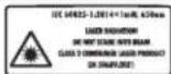
Laser radiation: Do not stare into the beam. Laser product class 2 per EN 50689:2021

Do not place your hands in the cutting area while the power tool is operating. Contact with the saw blade can cause injury.

Wear protective goggles.

Wear protective gloves.

Wear ear protection. Noise can damage hearing.

Danger zone! Keep hands, fingers, and arms away from this area.
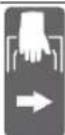
When transporting the power tool, hold it only by the designated handles (on the main handle) or by the carrying handle.

If the miter gauge is set at a vertical angle, the stop bar must be moved or removed entirely.
3601M511..
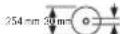
Pay attention to the dimensions of the saw blade. The arbor hole must fit the shaft without any gap. If necessary, use
3601M511B. 3601M5118.
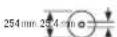
a reducing ring. Ensure that the reducing ring matches the thickness of the saw blade and the diameter of the arbor hole, as well as the shaft diameter. If possible, use a reducing ring.
Symbols
The blade must be used with the saw.
The saw blade diameter must match the data on the symbol.
Illustrated components
The numbering of the illustrated components refers to the illustration of the power tool on the page with the figures.
(1) Locking button for the miter gauge (2) Miter gauge stop (3) Transport handle (4) Protective cover lock (5) (6) Chip deflector (7) Handle (8) Lock for the blade guard (9) Blade guard release lever (10) Magnetic catch for the protective cover (11) Roller guide (12) Table (13) Mounting holes (14) Insert plate (15) Dust bag (16) Lever for fine adjustment of the miter angle (horizontal) (17) Lever for the crosscut stop and miter angle (horizontal)
(18) Anti-tip device (19) Laser warning label (20) Stops for standard miter angles (horizontal) (21) Scale for miter angle adjustment (horizontal) (22) Locking screw for the table extension (23) Table extension (24) Workpiece support (adjustable) (25) Fixed stop bar (26) Movable stop bar (27) Scale for miter angle (vertical) (28) Indicator for miter angle (vertical) (29) Deflector for chip flow (30) Saw blade (31) Fixing screw for the saw blade (32) Battery pack release button (33) Battery pack (34) Transport lock (35) Protection bracket against tipping (36) Spreading wedge (37) Container (38) Adjusting screw for the cutting depth (39) Depth stop (40) Threaded rod (41) Clamp (42) Clamp opening (43) Hex key/Flat wrench (44) Fixing screw for the miter angle (vertical) (45) Wing nut for miter angle (vertical) (46) Fixing lever for miter angle (vertical) (47) Mounting for the workpiece support (on the power tool) (48) Mounting for the workpiece support (on the workpiece support) (49) Bolt with fine thread (50) Auxiliary reducing ring for the saw (51) Screw with internal hex for the saw blade (52) Locking flange (53) Inner locking flange (54) Screw for the insert plate (55) Screw for the blade guard (56) Screw for the blade guard housing (57) Blade guard housing
264|Ukrainian
(58) Indicator for miter angle (horizontal)
(60) Screw for the angle indicator (vertical)
Patent (59) TBNHTIHNKATOPaKyta (horizontal)
(61) Application number Dny pyk
Technical data
| Актуарноа панелььни рплка GCM 18V-254 D GCM 18V-254 D | ||
| Товарноюмер | 3601 M51 1... | 3601 M51 1B. |
| 3601 M51 18. | ||
| Номиналын haура V= 18 18 | ||
| Частota обертыняхолостогохodyA) | ob/xB 4500 4500 | |
| Ти палега на 650 650 | ||
| MBT < 1 < 1 | ||
| Клас палега 2 2 | ||
| BaraB) | кг 17,7-18,7 17,7-18,7 | |
| Рекомендова темпера typа навковшильно сеpeданilla по зарджанhi | °C 0 ... +35 0 ... +35 | |
| Дорустima темпера typа habковшильно сeрedingида по по ekspл Anyataci i по зевиранhi | °C -20 ... +50 -20 ... +50 | |
| Рекомендоваюнia akumлайтоги батаpei GBA 18V... | ProCORE18V... | GBA 18V... |
| ProCORE18V... | ||
| Рекомендоваюнia заради посястrodu GAL 18... | GAL 18... | |
| GAX 18... | GAX 18... | |
| GAL 36... | GAL 36... | |
Dimensions of the working tool
Battery charging
To charge the battery, press the release button and remove the battery. Do not use force when inserting.
The battery is designed to prevent overcharging when the release button is pressed accidentally.
The battery installed in the power tool should be kept in the position shown in the figure.
Battery charge indicator
Note: Not all battery packs have a charge level indicator.
The green lights of the battery charge indicator show the charge level. To check the charge level, you can only use the power tool when it is switched off.
Press the battery charge indicator button or select the charge level.
This can also be done when the battery is removed from the power tool.
When the indicator button is pressed and the lights do not turn on, the battery is discharged and needs to be charged.
Battery type GBA 18V...


Discharge of 3 green LEDs 100%
Discharge of 2 green LEDs 30-60%
Discharge of 1 green LED 5-30%
Discharge of 1 orange LED 0-5%
Type of battery ProCORE18V...


Discharge minutes
Discharge of 5-13 LEDs 80-100%
Discharge of 4 green LEDs 60-80%
Discharge of 3 green LEDs 40-60%
Discharge of 2 green LEDs 20-40%
Discharge of 1 green LED 5-20%
Discharge of 1 orange LED 0-5%
Indication of optimal charging with battery
Grasp the battery by the handle.
The battery can be used at temperatures from -20°C to 50°C. However, do not immerse the battery in liquid.
When cleaning the ventilation openings of the battery, use a clean and dry cloth.
If the battery is short-circuited, it may overheat after charging. If this happens, the battery has failed and must be replaced.
Dispose of batteries properly.
Assembly
Before using the power tool, check that the battery is properly installed. When transporting or storing the battery, remove it from the power tool. If the tool is switched on unintentionally, there is a risk of injury.
Scope of delivery

The delivery includes the tool, instructions for use, and accessories.
Before using the power tool, check that all parts are present:
- Battery pack with mounting plate - Thrust wheels (45) - Adjustable stop plate (26) - Nozzle (41) - Hex wrench / screwdriver (43) - Container for dust (37) - Supports for workpieces (24) (2 pcs.)
Note: Check the power tool for the presence of all parts.
Before operating the power tool, check that all safety devices and moving parts are in good working order and that no parts are damaged. Ensure that all parts are correctly installed and that all conditions are met for safe operation.
Check that moving parts operate safely and do not jam, and that there are no damaged parts. For safe operation, all parts must be correctly installed and meet all requirements.
Damaged safety devices and parts must be repaired or replaced by a qualified specialist.
Assembly of individual parts
Unpack the power tool and accessories. Remove the power tool and all accessories from the packaging. The packaging is intended for transport and protects the power tool from damage during shipping.
INSTALLING THE WORKPIECE SUPPORT (SEE FIG. A1)
The workpiece support (24) can be mounted on the power tool on the right, left, or front. The plug-in system provides the possibility of various mounting positions or extensions (see Fig. G).
If necessary, mount the workpiece support (24) into the bracket (47) on the power tool or into the bracket (48) for the workpiece support. Never carry the power tool by the workpiece support. For transporting the power tool, use only the transport devices.
INSTALLING THE CLAMPING WHEEL (SEE FIG. A2)
The clamping wheel (45) fixes the vertical cutting angle and is necessary for safe operation.
Unscrew the hex nut from the threaded bolt (49). Screw the clamping wheel (45) onto the threaded bolt (49) by hand and tighten it.
INSTALLING THE ADJUSTABLE STOP RAIL (SEE FIG. A3)
The adjustable stop rail (26) must be reinstalled before sawing. Slide the stop rail (26) to the right or left into the corresponding groove and tighten the locking screw (44).
The dry wall of the stop rail must be pushed completely inward to the stop.
STATIONARY OR FLEXIBLE MOUNTING
To ensure safe working conditions, the power tool must be mounted on a level and stable surface (e.g., a workbench) before operation.
MOUNTING ON A WORK SURFACE (SEE FIG. B1-B2)
Using the provided screws, secure the power tool to the work surface through the holes (13).
Or, using the clamping spindle, clamp the power tool to the work surface with the clamping jaws.
Bosch power tool bench
The Bosch power tool bench ensures a secure position of the power tool on the work surface thanks to the adjustable height. The bench legs are used for supporting large workpieces.
Read all safety warnings and instructions before setting up the bench. Failure to follow the warnings and instructions may result in electric shock, fire and/or serious injury. Before mounting the power tool, correctly store the bench. Careful mounting is important to avoid the risk of the bench tipping over. -Mount the power tool on the workbench in the horizontal position for transport.
Improper mounting (not recommended!) (see Fig. B3)
If in exceptional cases it is not possible to clamp the power tool on a level and stable surface, it can be installed with the anti-tip protection.
Without anti-tip protection, the power tool stands unstable and may tip over, especially when cutting at maximum horizontal and/or vertical angles. -Screw in or unscrew the anti-tip protection (18) so that the power tool stands level on the work surface.
Dust/Chip Extraction
Dust from materials such as lead-containing paint, some wood types, minerals and metal can be harmful to health. Touching or breathing in the dust can cause allergic reactions and/or respiratory diseases in you or bystanders.
Wood dust, oak or beech dust is considered carcinogenic, especially in combination with additives for wood treatment (chromate, wood preservatives). Material containing asbestos may only be worked on by specialists.
-Always use the dust extraction device for dust extraction. Ensure good ventilation of the workplace. -It is recommended to wear a respirator with filter class P2.
Observe the regulations for the processed materials valid in your country.
Avoid dust accumulation at the workplace. Dust can easily ignite.
The dust/chip extraction device may become blocked by chips or workpiece fragments.
-Switch off the power tool and remove the battery. -Wait until the saw blade has come to a complete standstill. -Find the cause of the blockage and eliminate it.
Built-in dust extraction (see Fig. C)
For proper operation, use the container for dust (37). - Install the transport handle (3) vertically. Insert and screw the dust container (37) into the suction adapter (50) in such a way that the dust container is fully engaged in the suction adapter.
The dust container must not protrude beyond the moving parts of the tool in any case.
Empty the dust container in a timely manner.
Check and clean the dust container after each use. To avoid damage, remove the dust container when emptying it.
EXTERNAL SUCTION
For external suction, you can also connect a vacuum hose (50) with a diameter of 35 mm. - Insert the vacuum hose into the adapter (50). The vacuum must be suitable for the material being worked on. For suction of particularly fine, carcinogenic, or dry dust, a special vacuum is required.
Replacing the saw blade (see figures D1-D4)
Before any work with the power tool (e.g., maintenance, changing tools, etc.), as well as during transport and storage, remove the battery from the power tool. There is a risk of injury if the switch is unintentionally pressed. The saw blade must be mounted with protective gloves. Touching the saw blade poses a risk of injury.
Use only saw blades that are suitable for the maximum speed of the tool and the number of teeth of your power tool when running idle. Use only saw blades that meet the characteristics specified in these instructions, checked according to EN 847-1 and with appropriate marking. Use only saw blades recommended by the power tool manufacturer and suitable for the material to be cut. This prevents damage to the teeth and premature wear.
Removing the saw blade
- Place the power tool in the working position.
- Swivel the protective guard (10) backwards and hold it in this position. - Turn the screw with the internal hexagon (51) using a hex key (6 mm) (43) and simultaneously press the spindle lock (31) until it engages. - Keep the spindle lock (31) pressed and unscrew the screw with the internal hexagon (51) in the direction of rotation (right-hand thread!). - Remove the clamping flange (52). - Remove the saw blade (30). - Swivel the protective guard back down.
Mounting the saw blade
When mounting, ensure that the direction of rotation of the teeth (arrow on the saw blade) matches the direction of the arrow on the protective guard! If necessary, clean all parts to be mounted before positioning. - Swivel the protective guard (10) backwards and hold it in this position. - Place the new saw blade onto the inner clamping flange (53). - Put on the clamping flange (52) and screw in the screw with the internal hexagon (51). Press the spindle lock (31) so that it engages, and tighten the screw with the internal hexagon in the direction of rotation. - Swivel the protective guard back down.
Operation
Improper use of the power tool (e.g., technical maintenance, replacement of the working tool), as well as during transport and storage, may damage the battery of the power tool. If the power tool is switched on unintentionally, there is a risk of injury.
Transport fixing (see figure E)
The transport fixing (34) allows the power tool to be secured for safe transport after use.
Release the fixing (working position)
- Press the retaining bracket (7) downwards to release the transport fixing (34). - Pull the transport fixing (34) to the stop. - The retaining bracket must be fully released.
268|Ukrainian
Fixing the power tool (transport position)
- Press the locking button (1) and pull the trigger (2) downwards. Push the retaining bracket of the working tool forward until it stops, then release the locking button to secure the trigger. - Press the dust extraction hose (39) into the recess. - To fix the stop (12), tighten the fixing handle (16). - Press the retaining bracket of the working tool by the handle (7) downwards until the transport fixing (34) can be fully inserted inside.
The retaining bracket of the working tool is now securely fixed for transport.
Preparation for work
In order to ensure accurate alignment, after intensive use of the power tool, its basic parameters must be checked and, if necessary, corrected. This requires appropriate expertise and the use of special tools.
Bosch service centers perform this work only properly.
Raising/lowering the table (see figure F-G)
To raise or lower the table, the required height must be adjusted or set.
The table can be raised and lowered using the table adjustment (23).
- Tighten the locking screw (22) to fix the required length of the stop. - After fixing the stop, tighten the locking screw (22) again.
The workpiece support system (24) provides the ability to adjust the position or expand it.
- If necessary, install the workpiece support (24) on the power tool or on the support (48) of another workpiece support. Never carry the power tool by the workpiece support. When transporting the power tool, use the transport device.
Adjusting the tilt angle (see figure H)
The tilt angle can be adjusted horizontally and/or vertically as required according to the scale. To do this, loosen the locking lever (26) or remove it completely.
| Bertikalbni Kyt po3nnIOBAHNA | TopuzoHTaIbHI Kyt po3nnIOBAHNA | |
| 0°-22,5° (nibopy/ npabopy) | >0° | -BidnyctITb liBn/npaBn φiKcyuOuH rBnHT (44). -BitraHnITb liBy/npaBv nepeCyBHy ynpHy pnaHky (26)do KINZr Ha3OBHl. |
| 22,5°-47° (nibopy/ npabopy) | ≤48° (nibopy/ npabopy) | -BidnyctITb liBn/npaBn φiKcyuOuH rBnHT (44). -BitraHnITb liBy/npaBv nepeCyBHy ynpHy pnaHky (26)do KINZr Ha3OBHl. -PiDhImITb nepeCyBHy ynpHy pnaHky BrOpy i3HimITb II. |
Adjusting standard vertical tilt angles (see figure I)
- Loosen the locking lever (26) until it can be moved or completely removed. - Then adjust the stop (45). - Press the locking lever (46) and lock it in the desired position. In this way, the entire range of tilt angles (left and right) can be used. - Press the handle (7) to the left or right until the angle indicator (28) shows the desired standard vertical tilt angle. - Release the locking lever (46). The locking lever must engage in the position of the desired standard vertical angle. - Tighten the locking screw (45) again.
Adjusting the vertical tilt angles
- Loosen the locking lever (26) until it can be moved or completely removed. - Then adjust the stop (45). - Press the locking lever (46) and lock it in the desired position.
In this way, the entire range of tilt angles (left and right) can be used.
- Press the handle (7) to the left or right until the angle indicator (28) shows the desired vertical tilt angle. - Tighten the locking screw (45) again.
Operation
Before tilting, always loosen the locking handle (16) and the locking screw (45). Otherwise, the workpiece may be tilted.
Switching on (see figure J)
- To switch on the power tool, first press the lock-off button (5) inward, then press the on/off switch (6) and keep it pressed.
Important: Safety regulations must be observed. It is forbidden to lock it; it must be kept pressed throughout the entire work.
Switching on
To switch on the machine (6).
Adjustment
General instructions for adjustment
Before adjustment, firmly press the locking lever (16) and the coupling (45). The fabric may skew in the workpiece. During all adjustment work, you must ensure that the fabric cannot be caught by the needle plate, hoses, or other parts of the device. Use a suitable support or appropriate aids if necessary.
Protect the fabric from impacts. Do not press on the fabric from the side.
Place the material correctly according to its intended use.
Do not use damaged workpieces. The workpiece must have a straight edge for attachment to the support plate.
Long and heavy workpieces must be supported or placed on something.
Make sure that the pendulum guard moves freely and is properly secured for each operation. When the crank is lowered, the pendulum guard must open. When the crank is raised, the pendulum guard must close again over the fabric and lock in the raised position of the crank.
The emergency stop must be remembered.
- Set the electric tool to the working position. - Unscrew the screws (54) using a standard screwdriver and remove the cover (14).
- Insert the new insert and tighten the screws (54) again.
Sharpening
To check the laser functions, the power tool must be connected to a power source.
When moving the laser (e.g., when moving the bracket), never press on the switch. An unintentional start of the power tool may cause injury. - Set the power tool in the working position. - Turn the switch (12) to the ON position (20). The lock (17) must be engaged in the switch.
To ensure accurate marking during intensive use, it is necessary to check and, if needed, re-calibrate the laser beams.
Always use the correct and specialized tool.
Maintenance is performed as required.
Checking (see Fig. T1)
- Place the tool against the marking line. - Lower the bracket by the handle (7). Adjust the tool so that the saw blade tooth is exactly on the marking line. Hold the tool in this position and firmly press the bracket of the power tool. Then tighten the tool. - Switch on the laser using the switch (6), without pressing the laser button (5).
The laser beams must be at the same distance from the marking line on the workpiece along their entire length, both left and right, including when the bracket is moved downwards.
Replacing the laser battery (see Fig. T2)
- Loosen the screw (55) of the laser cover (8) using a hex key or cross-head screwdriver (43) and remove the laser cover.
Adjusting the laser beam when moving the bracket of the power tool (see Fig. T3-T4)
- Loosen the screw (56) (approx. 1-2 turns). Do not unscrew it completely. - Move the laser housing (57) to the right or left until, when moving the bracket of the power tool downwards, the laser beams no longer deviate. - Pull the laser housing (57) to the desired position and tighten the screw (56) again.
- Reinstall the laser cover (8).
Checking and adjusting the basic parameters
For accurate marking, after intensive use of the power tool, check its basic parameters and adjust them if necessary.
Specialized tool for adjusting the angle indicator.
Perform the following work only as specified.
Adjusting the angle indicator (horizontal) (see Fig. 1)
Set the power tool to the working position. - Turn the clamping lever (12) to 0°. The handle (17) must be turned fully to engage the locking mechanism.
Check
The angle indicator (58) must be aligned with the 0° mark on the scale (21).
Adjustment
- Loosen the screw (59) with a cross-head screwdriver and adjust the angle indicator to the 0° mark. - Retighten the screw.
Adjusting the angle indicator (vertical) (see Fig. 2)
- Set the power tool to the working position.
- Loosen the clamping screw (45). - Turn the stop screw (46) until the tool is perpendicular to the workpiece using the vertical angle scale. - Tighten the stop screw (46). The stop screw must be locked in position. - Retighten the clamping screw (45).
Check
The angle indicator (28) must be aligned with the 0° mark on the scale (27).
Adjustment
- Loosen the screw (60) with a cross-head screwdriver and adjust the angle indicator to the 0° mark. - Retighten the screw.
Transporting the power tool (see figure W)
Before transporting the power tool (e.g., for maintenance, replacing the tool), and also when transporting and storing it, remove the battery from the power tool. There is a risk of injury if the switch is accidentally activated. To transport the power tool, do the following: - Loosen the locking screw (1) if it is tightened. Push the tool holder to the stop forward and then tighten the locking screw again.
272|Ukrainian
- Make sure that the depth stop (39) is pushed all the way back and that the locking screw (38) does not protrude from the tool holder when it is moved. Place the power tool in the transport position. - Remove all accessories that can be mounted on the power tool. If possible, carry the dust bags that you are not using in closed containers. - Set the transport handle (3) vertically. - Carry the power tool by the transport handle (3) or by the side handle (61) on the side of the stand. For transporting the power tool, use the transport handle or the side handle. Do not use the protective guard or the stand as carrying aids.
Maintenance and service
Maintenance and cleaning
Before performing any work on the power tool (e.g., maintenance, replacing the tool), and also when transporting and storing it, remove the battery from the power tool. There is a risk of injury if the switch is accidentally activated. For safe operation, read the operating instructions carefully.
The protective guard must be able to move freely and close automatically. Therefore, keep the area around the protective guard clean.
Do not perform any risky operations on the structure, compressed air, or modify them.
Regularly clean the rollers (11).
Laws regarding dust extraction
Manufacturer's regulations:
- Smooth start - Nozzle with a special dust disc designed for changing the dust level during operation: - Installation that does not allow vibrations, stable surface, use of accessories that change the dust level - Regular cleaning of the dust disc and the power tool
Service and consultation on usage questions
In the service workshop, you will receive answers to your questions regarding repair and technical maintenance of your product. Detailed information about spare parts can be found at: www.bosch-pt.com
When contacting Bosch or a customer service center, please quote the product number and the 10-digit order number found on the product nameplate.
For any warranty claims or repairs, please provide the 10-digit order number that appears on the product nameplate.
Warranty service and repair of power tools are carried out in accordance with the requirements and standards of the manufacturer's country only in authorized or
authorized service centers of Robert Bosch GmbH. WARNING! Use of counterfeit products is unsafe and may have adverse health effects. Manufacturing and distribution of counterfeit products is prohibited by administrative and criminal law.
Ukraine
Bosch Service Center for Power Tools
1 Krainy St.
02660 Kyiv
Tel.: +380 44 490 2407
Fax: +380 44 512 0591
E-Mail: pt-service@ua.bosch.com
www.bosch-professional.com/ua/uk
Addresses of regional warranty service workshops are listed in the enclosed warranty card.
Addresses of other service centers are listed below:
www.bosch-pt.com/serviceaddresses
Transportation
It is recommended to use lithium-ion batteries for transportation of dangerous goods. Batteries can be transported by users by road transport without the need to obtain special permits.
When transporting by air (e.g., by air transport or by elevator), special packaging and labeling requirements must be observed. In any case, an expert in dangerous goods must participate in the preparation of the shipment.
Place the battery in a non-conductive casing. Close open contacts and pack the battery so that it does not move. Keep it away from possible additional metal objects.
Disposal

Electrical appliances, batteries, accessories and packaging must be handed over to an ecological recycling facility.
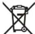
Do not dispose of electrical appliances and batteries in household waste!
Only for EU countries:
According to the European Directive 2012/19/EU on waste electrical and electronic equipment (WEEE) and its implementation in national legislation, electrical tools that are no longer usable, as well as according to the European Directive 2006/66/EC, defective or used batteries must be collected separately and recycled in an environmentally friendly manner. Improper disposal of used electrical and electronic equipment may have harmful effects on the environment and human health due to the possible presence of hazardous substances.
Batteries:
Lithium-ion:
Bulgarian, see section "Transportation" (see "Transportation" page 272).
Kazakh
Eurasian Economic Union (EEU) Conformity
This product has been certified in accordance with the requirements of the Technical Regulations of the Customs Union. The certificate of conformity is available upon request. The certificate is attached to the product packaging. The certificate is also available on the manufacturer's website. The product must be used in accordance with the instructions.
The device is intended for measuring temperature. Before starting the measurement, the device must be turned on (if the device has been stored for a long time, it must be turned on). The measurement result is displayed on the screen without text (service text). The device has the necessary technical characteristics for measuring temperature.
Measurement procedure
- If the device does not turn on, check the battery. - If the battery is low, replace it. - If the device does not turn on even after replacing the battery, check the power cord.
Precautions and warnings
If the device is damaged, do not use it. - Do not use the device outdoors in rainy weather. - Do not immerse the device in water.
Cleaning and maintenance
- Clean the device with a dry cloth. - Do not use abrasive cleaners.
Service life and storage
The service life is at least 5 years from the date of manufacture.
Storage
The device must be stored in a dry place. Avoid exposure to high temperatures and direct sunlight. During storage, protect the device from sudden temperature changes. Do not store the device in a humid environment. For storage conditions, refer to GOST 15150-69 (clause 1). Store the device at temperatures from +5°C to +40°C. Relative humidity should not exceed 80%.
Transportation
Transportation of the device is allowed by any type of closed transport. During loading and unloading, do not subject the device to shock or vibration. For transportation conditions, refer to GOST 15150-69 (clause 5). The ambient temperature during transportation should be from -50°C to +50°C. Relative humidity should not exceed 100%.
Safety instructions
For electric heaters, safety instructions
EXPERTS
This electric heater's instructions contain
instructions, figures, and specifications
read. All technical safety
instructions must be followed to avoid fire, electric shock, or injury to persons.
For your safety, follow the safety instructions and warnings.
The safety instructions include warnings about electric shock hazards (with symbol) and battery electric shock hazards (without symbol).
Safety of the heater
Do not use the heater outdoors. It may cause electric shock or fire.
274|Kazakh
Do not use the electric heater in explosive atmospheres, or where there is dust, flammable gas, or steam. The heater's parts may be hot, and they may ignite or be flammable. Children and caregivers should not operate the heater without supervision. In commercial settings, industrial areas, and public places, the heater must be used only for its intended purpose, considering environmental and safety factors.
Electric safety
Electric plugs must fit the socket. Do not modify the plug. Do not use adapters with the heater. Improper plugs and unsuitable sockets increase the risk of electric shock. If the plug, cord, or appliance is damaged, or if it has been dropped, the risk of fire or electric shock increases. Do not use the heater if it is damaged or malfunctioning. Do not operate the heater with a damaged cord or plug. Do not touch the heater with wet hands. Do not pull the cord to disconnect. Do not use the heater outdoors. Do not place the heater near water. Do not use the heater in bathrooms, near pools, or in wet areas. If the heater must be used in a wet area, use it with a residual current device (RCD) to reduce the risk of electric shock.
Safety
Electric current can be dangerous, harmful to health, and even fatal. Electric current can cause burns, electric shock, or even death. Electric current can be used to cause injury or damage. Keep all warning labels intact. Do not remove warning labels. If labels are damaged, missing, or illegible, replace them with new warning labels.
When working with electrical equipment, follow all safety instructions.
Before connecting the device, read the instructions. Only connect the device to a power source that matches the voltage and frequency specified on the rating plate. Connecting the device to a power source with incorrect voltage or frequency can cause damage to the device. Do not use the device if the power cord or plug is damaged. Do not operate the device with wet hands or when standing on wet surfaces. Keep the device away from water and moisture. Do not use the device near flammable liquids or gases. If the device is not working properly, disconnect it from the power supply and contact a qualified technician. Do not attempt to repair the device yourself. Only qualified personnel should perform maintenance and repairs. Use only original spare parts. WARNING! If the device is used in a way that is not intended, it may cause injury or damage. Always disconnect the device from the power supply before cleaning or maintenance. Do not pull the cord to disconnect the plug. Do not immerse the device in water or any other liquid. The device is intended for indoor use only. For safe operation, follow the instructions in this manual. The device must be operated by persons who are at least 18 years old, have read the safety instructions, and are aware of the risks. Do not allow children or persons with reduced physical, sensory, or mental capabilities to operate the device unless they are supervised. If the power cord is damaged, it must be replaced by the manufacturer, its service agent, or a similarly qualified person to avoid a hazard.
Electric current can cause injury.
The switches are installed in the off position. The required voltage for the electric switch is indicated. The required voltage for the electric switch is indicated on the nameplate. If the required voltage is not available, do not connect the electric switch. If the electric switch is to be installed in a damp or wet location, it must be protected. When cleaning, replacing fuses, or working on electric switches, disconnect the power supply first. If the switch or accumulator is damaged, do not connect it to the electric switch. These safety instructions are mandatory for the electric switch without exception. Only use electric switches with the specified voltage. Do not use this switch for loads other than those specified. Electric switches may become hot during prolonged use. Keep the electric switch and its accessories clean. Do not use the switch if the fuses are damaged or worn, or if the switch is damaged or worn. If the switch has damaged fuses, replace them before use. Improper use of electric switches can cause fires. Do not use damaged or old wires. If the wires are damaged or old, replace them with new ones. The electric switch, its contacts, and other parts are subject to wear. Follow the safety instructions when using the switch. Electric switches should be installed by qualified personnel. When connecting wires and cables, use clean and dry insulation. Do not allow moisture or dirt to come into contact with the switch contacts and cables.
Battery switch installation and maintenance
Only use the switch with the specified voltage. If a different voltage is applied, it may cause overheating and damage. Use electric switches only with the specified battery voltage. Using a different battery voltage may cause overheating and damage. If the battery voltage is not correct, do not connect it. Install the switch away from heat sources such as stoves, radiators, or other metal parts.
Terminal connections may be made in any order. The terminal connections may be made with any type of connector or directly.
The battery may contain hazardous substances, so it must be disposed of properly. If the battery is damaged, replace it immediately. If the battery comes into contact with skin, seek medical attention. The battery may be removed or replaced only by qualified personnel. Do not disassemble, puncture, or incinerate the battery. Do not expose the battery to high temperatures above 130°C, as this may cause fire or explosion. Do not short-circuit the battery or connect it to metal objects. Do not use the battery in environments with temperatures outside the specified range. If the battery is damaged or shows signs of leakage, it must be replaced immediately.
Service instructions
Electrical safety: Only use the device with the provided power cord. This ensures the safety of the electrical circuit. Do not touch the battery contacts with wet hands. The battery may only be replaced or serviced by authorized personnel.
Safety instructions for the user
For cleaning, use a soft, dry cloth. Do not use abrasive cleaners, solvents, or other chemicals. Do not immerse the device in water or other liquids. If the device becomes wet, dry it thoroughly before use. Do not use the device if it is damaged. Keep the device away from heat sources and open flames. Do not expose the device to temperatures above 60°C. If the device is not working properly, contact a qualified technician. Do not attempt to repair the device yourself. Use only the specified power adapter. Do not use the device if the power cord is damaged. Keep the device out of reach of children.
To clean the device, first disconnect it from the power source. Then wipe the exterior with a soft, dry cloth. Do not use any liquids or sprays. If the device is heavily soiled, use a slightly damp cloth and dry it immediately. Do not immerse the device in water. Do not use abrasive materials. For stubborn dirt, use a mild detergent diluted in water, then wipe with a dry cloth.
Follow all safety instructions, warnings, and precautions listed in this manual. Use the device only for its intended purpose as described in the manual. If the device is used in a manner not specified by the manufacturer, the protection provided by the device may be impaired. Keep the manual for future reference. If the device is damaged or malfunctions, do not use it and contact qualified personnel for inspection. Do not attempt to repair the device yourself. Only use accessories and spare parts recommended by the manufacturer. Do not use the device in explosive atmospheres. Keep the device away from children and unauthorized persons. Do not operate the device with wet hands. Do not expose the device to rain or moisture. If the device is dropped or damaged, have it checked by qualified personnel before further use. Do not use the device if the power cord or plug is damaged. Do not pull the cord to disconnect the plug. Do not use the device near flammable liquids or gases. Do not block the ventilation openings. Do not insert objects into the openings. Do not use the device if it emits smoke or unusual odors. Disconnect the device from the power supply before cleaning or maintenance. Do not use abrasive cleaners or solvents. Store the device in a dry place. Do not dispose of the device in household waste. Follow local regulations for disposal. If you have any questions, contact the manufacturer or authorized service center.
YcTeN KeHeHTKiWi HEmeCe KocbIMMa Tipeyi OphbHa 6aKa aAaMdbI naDanaH6aHb3. DaNbIHdMa TypaKtBf 6ekTINMeCE DnCKi KbCbNybl HEmeCe DaNbIHdMa Kecy Ke3iHne KblKnbl, ci3i He KeMeKwH3di aiHaBbIn TypFaH dNCKIRE KaKbIHdATybl MyMKH.
KecinreH 6oIeK TybIn KAnMaybHemece aHnBIn tyPah apu Dnckiche BacbImaybTnic. WKeTren Hc0nca, MbCaIbI, y3bHbIK WKeTeyneI apkblb, KeCinreH 6oIeK DnCKIRE KbICbIn KaTbNaKTbPbIyMbMYMKIN.
Hb6KHeMece Ky6bp CnKtBdOmaNk MaepHaanap yuH epaibim KbickbiH HeMece 6ekitkiwi naDanaHbHb3. H6bkTap kecinreHHen COH Domanan KeTyI MyMKiH, MyHa dNcKi TICTEN DaBHdAmahb KoIbHb3eH bipre dNcKire TaTpby MymKH.
DaiBihdamaFaTHIODeHAnDbIH DNCKI TOBbIK XbINDaMdbfBHaXeTyKepeK. Byn daBihdama NaKtbpblny Kayinih KEMITEi.
Erep daibihdama Hemece dncki typbin kanca, 6ypbIbIK apaHbI eipiH3. Bapnbik icten typran 6oIweKTEpDIn TOKTAFaHBn KYTIN, aAhaHbKYat Ke3iHeH WbIFapBbH3/Hemece 6aTaper KHaFbH NbIFapBbH3.CocbH Tybpin KaFAN MATEPHANDbI WbIFapBbH3.Daibihdama Tybpin KaFAN Ke3Je apaaydbj XaNfactbpy 6ypbIbIK apaHbN 6akblaybI KOranybHa Hemece 3aKbIMdanybHa anbln Kenyi MYMKH.
Apanaydba aKaTaHaHn coeipriwiXi6epin, apa 6acbH ToMeH yCTan, Kecirren BoWeKeTI bIrapap anDbH AnckHH ToKtaybH KyTih3. Ncki aHaHbn tyPFAH Ke3De OFaH KonDbJ KaKbHdTu ETe Kayinti.
TOnbIKEMEC KecikTI opbIHdaFaHda Hemece 8uipriwi Xi6epReHHe TyKaHbI apa 6acbl TOnbIFbIMeTHMeHRI KYIre TYcKeHWe KaTbI YCTaHbI. ApaBHIOKtay opekeTI apa 6acbl Ke3deNcoKTeMeHRI TaTbIN JapaKaTTAHy KayinIne anbIn Kenyi MymKiH.
Apa 6actneri en actbHfbkyre keTkeh Ke3de, tykahbl xibiepmehi. Apa 6actnerin apdaibim KOmeh en XOFapfbl KYRE KaTapbHbI. Erep apa 6actneri 6akblaycb1 kblkbica, 6yn japaat any kayin Tydbip aanabl.
XyMbIC opHbIH Ta3a YcTaHbI3. MaTePnA KocanapBte Kayinti.KeHIn MetAn WaHb KaHbN JApbNy MyMkiH.
Otnec, kapbinaf, Kncatbnfah Hemece 3aKbIMdanfah apanay dnckinepi naindaanhaib3. Apanay dnckinepi hemece aybitkbfaH ticep eHci3 Kecyre, aptbik ykenicke, Typbin kanyra xHe Kepi cokkbifa ekenyimymkin.
Te3 kecetih 60nattan Xacanfah, Te3iminiri Xofapb apanay nckinepi naianaH6aHb3. Mynaiapanay nckinepi OHai cbHybl MmkiH.
Inipk Teciktepi Dpybc niimde (pom6) xhe Ownemde 60nabH Ky3epdi naDanaHbHb13. ApaHbOpHaTy KypaIapbHa cai 6oNMaFaH nickinepe TehePImde 60nMa, 6akblay XofantyBaHa anbl Keenedi.
3neKtp Kypanbl ICTen TpyraHa KeCy KaIbIKTapbIH, aFaw XohKaIapbIH T.6.KeCy aHMaFbIHah
The operator must ensure that the equipment is properly grounded before use.
Do not look directly into the laser beam. If laser radiation hits the eyes, there is a risk of injury. The battery must not be short-circuited or damaged. The battery may leak or overheat. If the battery comes into contact with skin or clothing, rinse with water. Do not expose the battery to high temperatures. Do not disassemble the battery. There is a risk of explosion. Do not short-circuit the battery with metal objects or external conductors. Do not heat, puncture, deform, or incinerate the battery. Batteries should only be charged with the chargers specified in the instructions. Keep the battery away from fire and excessive heat.

Protect the battery from moisture, rain, high humidity, extreme temperatures, fire, impact, and mechanical damage. Do not use damaged or leaking batteries.
The electrical equipment must be connected to a power source that matches the specifications (see "Specifications and Description"). If the power cord is damaged, have it replaced by the manufacturer or a qualified electrician. The electrical plug must be easily accessible.

Do not operate the laser device in explosive or flammable atmospheres. Do not point the laser beam at people or animals. Do not look into the beam or at reflective surfaces.
If the laser beam is directed at your eyes, you must immediately look away. Do not place the device in a position where the beam could accidentally hit someone. Only use the device as described in this manual. Do not allow children to use the electrical equipment without supervision. They could injure themselves or others.
Specifications
The following specifications apply to the electrical equipment. Keep the specifications and descriptions for future reference. Explanation of symbols
This symbol indicates that the electrical equipment is protected against direct contact with water.
Specifications and description
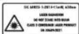
The laser device complies with the requirements of Class 2 laser product according to EN 50689:2021.

When the electrical equipment is switched on, do not look directly into the beam. Do not point the beam at people or animals.

Wear protective goggles.

Wear protective gloves.

Keep protective covers in place. Do not operate the device without them.

Danger of explosion! Do not expose the battery to fire, heat, or impact.

Installation and connection of the device (standard version) or installation and connection of the device with a remote control.
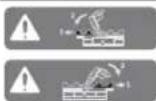
When checking the tightness of the connections, it is necessary to open the shut-off valves or remove the plugs.
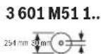
Check the device's O-ring. The nominal diameter of the pipe must match the diameter of the O-ring. If it is necessary to replace the O-ring, the O-ring must be replaced together with the device, and the nominal diameters of the pipe and the O-ring must be checked.
3601M511B. 3601M5118.
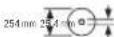
The nominal diameter of the device must match the required diameter.
Electrical and gas connection diagram
Read the safety instructions and warnings. Safety instructions and warnings must be observed to prevent injury or damage to property.
Check the initial pressure of the expansion tank.
Setting the pressure switch
Electrical connections must be made by qualified personnel in accordance with the wiring diagram. The permissible ambient temperature range is from -48°C to +48°C, with a maximum humidity of 47% (relative humidity) and 47% (absolute humidity).
The electrical connection must be made with a cable that is suitable for the ambient conditions and the type of protection required.
The device must be installed in a location that is easily accessible for maintenance and inspection.
This device complies with the EN 50689 standard for laser safety.
Replacement of the filter element
The filter element must be replaced with a genuine spare part from the manufacturer.
(1) Spare parts for the main unit (2) Spare parts (3) Control panel (4) Housing cover (5) Cover for the spare parts compartment (6) Spare parts (7) Button (8) Laser housing cover (9) Laser safety switch (10) Magnetic housing cover (11) Fuse (12) Protective device (13) Motor safety switches (14) Shaft (15) Fuse holder (16) Belt for the main drive (spare) (17) Belt for the drive, lower part (spare) (18) Housing for the spare parts (19) Laser expert switch (20) Standard accessories for the drive (spare)
(21) Drive belt cover (spare) (22) Protective device for the main unit (23) Protective device cover (24) Lower belt (for the drive) (25) Standard switch plate (26) Safety switch plate (27) Drive belt cover (part) (28) Drive belt indicators (part) (29) Fuse holder (30) Spare part (31) Main switch (32) Battery charging socket (33) Battery (34) Control panel cover (35) Housing for the spare parts (36) Safety switch (37) Shaft cover (38) Drive belt for the drive unit (39) Drive unit (40) Spare part kit (41) Spare part kit (42) Spare part kit safety switches (43) Spare part for the drive belt (44) Safety switch plate holder (45) Drive belt cover (part) (46) Drive belt holder (part) (47) Spare part for the lower belt (electrical connection) (48) Spare part for the lower belt (lower belt) (49) Spare part bolt (50) Spare parts (51) Spare part for the drive belt (52) Short fuse (53) Long fuse (54) Spare parts for the shaft (55) Spare part for the laser housing cover (56) Spare part for the laser housing (57) Laser housing (58) Belt indicators for the drive (spare) (59) Belt indicator holder (spare) (60) Belt indicator holder (part) (61)
Technical specifications
| Аккуmarлары Клиьдik.apa GCM 18V-254 D GCM 18V-254 D | ||
| Одирnomулип | 3601 M51 1.. | 3601 M51 1B. |
| 3601 M51 18. | ||
| Номиналды Керней V=18 18 | ||
| Бос курс Кундleri ai hyа lyжiniiriA) | MHN-1 | 4500 4500 |
| Пазер Тур iн 650 650 | ||
| MBT<1<1 | ||
| Пазер Класы 2 2 | ||
| СалмарыE) | КТ 17,7-18,7 17,7-18,7 | |
| Зарадтay Кeziндleri Yсынлалын Коршаган opta Tempanatypасы | °C 0 ... +35 0 ... +35 | |
| Жуmbic КeziндeriC)Жэhe сад耗ay Кeziндeri руksat etilген Коршаган optra Tempanatypасы | °C -20 ... +50 -20 ... +50 | |
| Усынлалын Аккуmarлар GBA 18V... | ProCORE18V... | GBA 18V... |
| ProCORE18V... | ||
| Усынлалын Зарадтавiiш Курblалap GAL 18... | GAX 18... | GAL 18... |
| GAL 36... | GAX 18... | |
| GAL 36... | ||
List of spare parts
Installation of the Bosch koumiss unit
The Bosch koumiss unit is designed for the preparation of koumiss from mare's milk. The unit is equipped with a drive motor and a control system.
The koumiss unit must be installed by qualified personnel. Experts and
specialists must be consulted before installation. The unit must be installed in a dry, well-ventilated area.
The electrical connection must be made by a qualified electrician. To avoid damage, the unit must be grounded. - The electrical connection must be made in accordance with the regulations.
Installation instructions (for the user!) (see figure)
If the electrical connection cannot be made in a dry place, the unit must be installed in a location protected from moisture.
The plug can be disconnected from the socket by pulling the plug, not the cable, at the maximum horizontal or vertical angle. -When unplugging (18), pull the plug from the socket by holding it firmly.
Cleaning and maintenance
The housing, various parts, minerals and metals may contain materials that can be harmful to health. Allergic reactions or respiratory problems may occur when cleaning or replacing the filter, or when in contact with dust. Dust particles, fibers and animal hair can be carcinogenic when combined with chemicals (chromium, protective agents). Asbestos materials must be removed by specialists.
-Possible damage: For this material, use only the specified cleaning agents. Avoid contact with solvents. -The P2 filter must be replaced according to the instructions. -Do not use aggressive cleaning agents or abrasive materials.
You have been warned about the dangers of improper use. Follow the instructions.
Do not use the device without the filter, filter or dust bag. -Do not operate the vacuum cleaner without the dust bag or filter. -Do not use the device without the filter or dust bag. -Do not use the device without the filter or dust bag.
Water filter (see figure C)
To install the filter, place the filter (37) as shown.
-Insert the plug (3) into the socket. -Press the On/Off button (37), the indicator light (50) will illuminate, and the device will start.
The device is equipped with a thermal overload protection.
Do not operate the device without the filter.
282|Kazakh
- After replacing the filter, dispose of the old filter properly. To ensure optimal performance, replace the filter regularly.
External filter
For water filtration, use the water filter (50) with the foam filter (diameter 35 mm) and insert it into the holder. -Insert the foam filter into the water filter (50). The foam filter must be in contact with the material. For health and safety, use the water filter as described.
Replace the cutting blade (D1-D4 cutting discs).
Before starting work with the battery-powered tool (sawing, cutting, grinding, etc.), remove the battery pack from the tool. Use only sharp, undamaged cutting discs. Replace worn or damaged cutting discs immediately. Do not use cracked or deformed cutting discs.
Maximum permissible speed of the cutting disc must be higher than the no-load speed of the tool.
When using the tool, always follow the safety instructions for cutting discs according to EN 847-1.
Use only cutting discs that are suitable for the tool and the material to be cut. Do not allow the disc to overheat.
Replacing the cutting disc
- Disconnect the tool from the power supply. Press and hold the spindle lock button (10), then turn the spindle lock until it engages. Use the hex key (6 mm) (43) to loosen the clamping screw (31) by turning it counterclockwise. - Remove the clamping screw (31), the outer flange (51), and the cutting disc (30). - Remove the inner flange (52). - Install the new cutting disc (30). - Reinstall the outer flange (51) and the clamping screw (31). Tighten the clamping screw by turning it clockwise while holding the spindle lock button.
Installing the cutting disc
When installing the cutting disc, ensure that the cutting disc is correctly seated on the spindle flange and that the clamping screw is tightened securely.
If necessary, replace the worn flanges with new ones.
Press and hold the spindle lock button (10), then turn the spindle lock until it engages. - Place the cutting disc on the inner flange (53). - Install the outer flange (52) and the hex key (51). Tighten the clamping screw (31) by turning it clockwise. Press the spindle lock button again to release it.
Operation
Before starting work with the battery-powered tool (sawing, cutting, grinding, etc.), remove the battery pack from the tool. Use only sharp, undamaged cutting discs.
During operation, hold the tool firmly (see figure E).
During operation, hold the tool with both hands (34) to maintain control and avoid kickback.
Electric power tool intended for cutting (dry cutting)
- Do not touch the cutting disc (7) with your hands. - Do not use the cutting disc (34) without its guard. - Do not operate the power tool without the guard.
Electric power tool intended for cutting (dry cutting)
- For cutting with a guide rail (1), insert the guide rail adapter (2) and tighten it. Pull the guide rail adapter back to release it. Remove the protective cover (39). - For cutting with the guide rail (16), pull the guide rail adapter (12) and insert it. Turn the power tool (7) and the cutting guard (34) together.
The power tool is suitable for dry cutting.
www.bosch-pt.com/serviceaddresses
If the power tool is damaged despite careful manufacturing and testing, it should be repaired by an authorized after-sales service for Bosch power tools.
- Mechanical damage; - Signs of damage to the housing or the power tool; - Damage to the housing, the housing parts, or the power tool; - Damage to the power cord or plug; - Damage to the power tool's insulation.
In case of damage, the following must be observed:
- Do not use the power tool if it is damaged; - Have the power tool repaired by a qualified person using only original spare parts.
Before any work on the power tool (e.g., maintenance, cleaning, etc.), remove the battery from the power tool.
- Do not expose the power tool to rain or wet conditions. - Do not use the power tool in areas with a risk of explosion, in the presence of flammable liquids, gases, or dust. - Do not use the power tool if the switch does not turn it on and off. - Do not use the power tool if it is damaged or if parts are loose.
Have the power tool repaired by a qualified person using only original spare parts.
Dry cutting
Use only sharp, undamaged cutting discs. Do not use damaged or deformed discs.
YuiHui TynfanaP (Mbicnbl, 3ye Keiiri Hemece Xiepepy) opamara KHe MapKaIapra KoBbIaTH apHaJI TaIantapdbCaKtay Kepek. Xiepepye daBihday KezIHne Kayinti KyKTepiTacbImday MAmhBMeH xa6apnacy Kepe.
AkkymyIaTOpIbI KOpnyCbI 3AkBIMdaIHa60ncaFaHa Ki6epiH3.AuBik TyicnepePi JKeimdeH3KaHe aKKMyIaTOpIbI opMaDa KO3FaImaTbIHdApHaH3.KaKeT 60nca,KocBIMua yTTbIK epexepePdi caKaTaHbI3.
Kedere kapaTy

3NeKtp KypaIapdbi, AkymyIaTOpIaPdbi, Kepe-KapaKaTApdbi XeHe opay MaTePhaIapdbH 3KOIOrHbIK TpyfbIaH DpybcYTHIN3aUHaayra Tancbipy Kepe. 3NeKtp KypaIapdbi XeHe aKKymyIaTOpIaPdbI/6atapeaIapdbI yIKoKbICbHa TaCTAmHaBla!
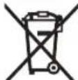
Tek kaHa EO eneepi yuH:
EckneKtpnik KHe 3eKtpOihbIK Kpyblfbnap Typanbl 2012/19/EU eyponaBik, dIpeKTHBaCbi KHe OHbH yTTbIK 3aHaMaJa KaONdaHbInybl BoBHnla NaIdAnaHyfa 6yDah 6blnA kapaMcbI 3eKtpnIK KpyanapDbI KHe 2006/66/ EC eyponaBik, dIpeKTHBaCbi 6oBHnla 3akbIMdanFaH Hemece eckipren AkkyMylTOpnapdb/6aTaepennapdb 6eK KHHan, KopwafanOpTa YwIH Kayinci KOnmeh KaTa eHdeye KjibepyKaket.
KaTe KOnMeH KaDeRe JkapTaBnFAh EckI 3NeKtpNik XHe 3NeKtpOnDbIK KypbInBnIap Kayinti 3aTAPdbH Bony MymKInDirine 6aHaNaHbICTbI KopWraH opTara XHe aam DeHcayNbFbHa 3HHDbI acep TIRi3yIMymKIn.
AkkymyTOpnap/6aTapeennap:
JIHTHNIHOHNbIK:
TacbImaNday6enimHderiHyckaynapdbOpbHaHb3 (KapaHb3,TacbImaNday",Bet288).
Româna
Instruţiuni de siguranta
Service scule electric
Strada Horia Macelariu Nr. 30-34, sector 1 013937 Bucuresti
www.bosch-pt.com/serviceaddresses
Transport
Lithium-ion accumulators are recommended to comply with the legislation regarding the transport of dangerous goods.
The accumulators can be transported by road without restrictions by the user.
Safety instructions
General safety instructions for safe work
WARNING! Read all safety warnings and all instructions. Failure to follow the warnings and instructions may result in electric shock, fire and/or serious injury.
Save all warnings and instructions for future reference.
The term "power tool" in the warnings refers to your mains-operated (corded) power tool or battery-operated (cordless) power tool.
Work area safety
Keep work area clean and well lit. Cluttered or dark areas invite accidents. Do not operate power tools in explosive atmospheres, such as in the presence of flammable liquids, gases or dust. Power tools create sparks which may ignite the dust or fumes. Keep children and bystanders away while operating a power tool. Distractions can cause you to lose control.
Electrical safety
Power tool plugs must match the outlet. Never modify the plug in any way. Do not use any adapter plugs with earthed (grounded) power tools. Unmodified plugs and matching outlets will reduce risk of electric shock. Avoid body contact with earthed or grounded surfaces, such as pipes, radiators, ranges and refrigerators. There is an increased risk of electric shock if your body is earthed or grounded. Do not expose power tools to rain or wet conditions. Water entering a power tool will increase the risk of electric shock. Do not abuse the cord. Never use the cord for carrying, pulling or unplugging the power tool. Keep cord away from heat, oil, sharp edges or moving parts. Damaged or entangled cords increase the risk of electric shock. When operating a power tool outdoors, use an extension cord suitable for outdoor use. Use of a cord suitable for outdoor use reduces the risk of electric shock. If operating a power tool in a damp location is unavoidable, use a residual current device (RCD) protected supply. Use of an RCD reduces the risk of electric shock.
Personal safety
Stay alert, watch what you are doing and use common sense when operating a power tool. Do not use a power tool while you are tired or under the influence of drugs, alcohol or medication. A moment of inattention while operating power tools may result in serious personal injury.
Before using the device, read the instructions carefully and use it sensibly. Do not use power tools when you are tired or under the influence of drugs, alcohol, or medication. A moment of inattention while working with power tools can lead to serious injury.
Working with power tools. Always wear safety glasses. Wearing appropriate clothing for using power tools and performing maintenance operations, such as a dust mask, protective non-slip footwear with steel toe caps, protective gloves, and hearing protection (anti-noise), reduces the risk of injury. Keep the tool away from the power source before switching on. Before connecting the tool to the power supply or inserting the battery, and also when handling the power tool, make sure that the switch is in the "Off" position. Turning on the power tool with your finger on the switch or supplying power while the switch is on increases the risk of injury. When carrying the power tool, make sure that it is not connected to the power source or battery. A power tool held by the moving part may cause injury. Avoid awkward body positions. Maintain a stable stance and keep your balance at all times. This allows you to control the power tool better and more safely in unexpected situations. Work with appropriate clothing. Do not wear loose clothing or jewelry. Keep your hair and clothing away from moving parts. Loose clothing, jewelry, or long hair can get caught in moving parts. If dust extraction and collection equipment is available, make sure it is connected and used properly. Using dust extraction reduces dust-related hazards. Familiarity with the power tool through frequent use does not justify neglecting safety rules. A careless action can cause serious injury in a fraction of a second.
Safety Warnings for Power Tools
Do not misuse the power tool. Use the power tool only for its intended purpose. Working with a suitable power tool for the application is safer and more efficient. Do not use the power tool if the switch is defective. A power tool that cannot be turned on or off with the switch is dangerous and must be repaired.
Pull the plug from the socket before making any adjustments to the power tool, changing accessories, or storing the tool. Such preventive safety measures reduce the risk of starting the tool accidentally. Store power tools out of the reach of children and do not allow persons unfamiliar with the power tool or these instructions to operate the power tool. Power tools are dangerous in the hands of untrained users. Maintain power tools and accessories. Check for misalignment or binding of moving parts, breakage of parts and any other condition that may affect the power tool's operation. If damaged, have the power tool repaired before use. Many accidents are caused by poorly maintained power tools. Keep cutting tools sharp and clean. Properly maintained cutting tools with sharp cutting edges are less likely to bind and are easier to control. Use the power tool, accessories and tool bits etc., in accordance with these instructions, taking into account the working conditions and the work to be performed. Use of the power tool for operations different from those intended could result in a hazardous situation. Keep handles and grasping surfaces dry, clean and free from oil and grease. Slippery handles and grasping surfaces do not allow for safe operation and control of the tool in unexpected situations.
Safety Warnings for Battery-Operated Power Tools
For charging the battery pack, use only the charger specified by the manufacturer. Using a charger with a different battery pack may create a risk of fire. Use only the battery pack specifically designed for your power tool. Use of any other battery packs may create a risk of injury and fire. When battery pack is not in use, keep it away from other metal objects, like paper clips, coins, keys, nails, screws or other small metal objects, that can make a connection from one terminal to another. Shorting the battery terminals together may cause burns or a fire.
Under abusive conditions, liquid may be ejected from the battery; avoid contact. If contact accidentally occurs, flush with water. If liquid contacts eyes, additionally seek medical help. Liquid ejected from the battery may cause irritation or burns.
Improper use of the battery may cause electric shock. Avoid contact with it. If this happens to your skin, rinse immediately with plenty of water. If electrolyte gets into your eyes, rinse immediately with plenty of water and seek medical help. The battery can cause skin burns. Do not use battery-powered power tools that are damaged or have been modified. Damaged or modified batteries may ignite and cause fire. Do not expose the battery to high temperatures or fire. Exposure to temperatures above 130°C may cause explosion. Follow all charging instructions for the battery; do not charge it if the temperature is outside the range specified in the instructions. Incorrect charging or charging at temperatures outside the permitted range may damage the battery and increase the risk of fire.
Maintenance
Have your power tool serviced only by qualified personnel using only original spare parts. This ensures the safety of the power tool. Never repair damaged batteries. Battery repair should only be carried out by the manufacturer or an authorized service provider.
Safety warnings for circular saws
The circular saw is intended for cutting wood and wood-like materials. It must not be used with abrasive cutting discs for cutting ferrous metals such as profiles, pipes, rods, etc. Abrasive dust may cause jamming of moving parts, e.g., the lower guard. Sparks from abrasive cutting may ignite the lower guard or other plastic parts. Use suitable clamps to secure the workpiece whenever possible. If you hold the workpiece by hand, it must be at a distance of at least 100 mm from the saw blade (front or back). Do not use the circular saw to cut pieces that are too small to be safely clamped or held by hand. If you hold the workpiece by hand,
with the circular saw blade, there is a high risk of serious injury if the blade kicks back.
Before cutting, the workpiece must be secured with screw clamps or pressed against the support plate and the workbench. During cutting, do not hold the workpiece with your hands or let it hang freely. Unsecured or moving workpieces can be pulled in and ejected at high speed, causing injuries. When cutting, always use the protective guard. Do not remove the protective guard. To cut the workpiece, lower the cutting head slowly, without jerking, switch on the motor, lower the cutting head slowly, and feed the workpiece through the cut. When cutting along the direction of the arrow, there is a risk that the circular saw blade may get caught in the workpiece and the saw may kick back with great force. Never cross the cutting line with your hands, neither in front of nor behind the circular saw blade. Holding the workpiece with crossed hands, i.e., holding the left side of the workpiece with the right hand or vice versa, is very dangerous. Do not place your hands closer than 100 mm from the front or rear edge of the circular saw blade. To remove jammed waste, first switch off the saw and wait for the blade to stop. The blade may still be spinning even when not visible, so wait for it to stop completely. Before cutting a workpiece, inspect it carefully. If it is warped or twisted, press it firmly against the support plate. Always make sure that the cutting line has clearance between the workpiece, the support plate, and the workbench. Warped or twisted workpieces can cause sudden jamming of the blade. The workpiece must not contain nails or other foreign objects. Do not switch on the motor while the workbench is not clean of sawdust, tools, scraps, etc.; only the workpiece should be on the workbench. Small workpieces or loose scraps may be caught by the spinning blade and ejected at high speed. Cut only one workpiece at a time. Workpieces stacked together cannot be clamped properly and may shift during cutting, causing the blade to jam. Before starting work, make sure the circular saw is securely attached to a stable surface. Securing to a stable surface is dangerous if the saw is unstable. Plan your actions carefully. Every time you change the bevel angle in the vertical or horizontal plane, ensure that the adjustable support plate is correctly mounted and does not interfere with the blade or the guard. Without switching on the machine, clamp the workpiece and lower the circular saw blade to the cutting depth to ensure there is no contact with the support plate.
Before entering the pit, make sure that the support leg is properly adjusted and that the machine is on a horizontal plane. Without starting the machine, manually rotate the disc by hand to ensure that it does not come into contact with the support leg.
When cutting off parts or pieces, always release the clamp gradually, e.g. with the release lever. Parts or pieces that are not held or clamped securely can be thrown off the rotating machine. If a sheet or part is thrown off, it can cause serious injury or open a wound when it hits the rotating disc. Do not allow other people to hold the free end of the part being cut off. The unsecured free end can hit the disc or cause displacement of the part during the cut and can pull you or assist you towards the rotating disc. The cut-off part must not be pressed against the rotating disc in any way. If it is restricted, e.g. by a length stop, the cut-off part can get caught in the disc and be thrown out with great force. When cutting off threads or pipes, always use brackets or clamping elements intended to hold the part securely. When cutting threads and pipes with a cut-off wheel, there is a tendency to jam, which causes kickback and there is a danger that the rotating disc will hit your hand. Before switching on the rotating disc, make sure it has reached its nominal speed. This reduces the risk of the cut-off part being thrown out. If the part or the rotating disc gets jammed, switch off the machine immediately. Examine all moving parts to see if they are stuck, switch off the machine and/or remove the battery pack before releasing the jammed element. Continuing to work with a jammed part can lead to loss of control or damage to the rotating machine. After switching off the machine, wait until the blade has come to a complete stop before removing the cut-off piece. Do not place your hands near the rotating blades of the disc. The rotating disc can cause kickback, which increases the risk of injury from the cutting disc.
Release the handle only when the saw head has reached the lowest position. Then turn the handle of the saw head back to the highest position. If the saw head moves uncontrollably, there is a risk of injury. Keep the workpiece steady. The material mixture is particularly dangerous. Dust from metal cutting may ignite or explode. Do not use damaged, cracked, bent, or broken circular saw blades. With circular saw blades with cracked teeth or tooth gaps, the friction increases as a result of the pressure and there is an increased risk of breakage. Do not use circular saw blades made of high-speed steel (marked HSS). Such circular saw blades are brittle and break easily. Only use circular saw blades with the correct size and shape (diamond or round) and with the correct bore hole. Circular saw blades that do not fit the mounting dimensions of the machine shaft will run eccentrically and may cause loss of control. Never attempt to remove debris, chips, or similar from the cutting area while the power tool is running. First, turn the power tool off and disconnect it from the power supply. After stopping work, do not touch the saw blade until it has cooled down. During operation, the saw blade heats up considerably. If the battery is damaged or used incorrectly, vapors may be emitted. The battery may ignite or explode. Ensure good ventilation and consult a physician if necessary. Vapors may irritate the respiratory tract. Do not open the battery. There is a risk of short circuit. The battery may be damaged by pointed objects, e.g. nails or screwdrivers, or by impact. This may cause a short circuit and the battery may ignite, explode, or overheat. Use the battery only in the product of the manufacturer. Only then is it protected against overload.

Protect the battery from high temperatures, e.g. from prolonged exposure to direct sunlight, fire, dirt, water, and moisture. There is a risk of explosion and short circuit.
The power tool is supplied with a laser warning label (see table "Symbols and their meanings").
If the text on the laser warning label is not in your language, cover it with the enclosed label in your language before commissioning. Do not damage the warning labels on the power tool.

Do not point the laser beam at people or animals and do not look directly into the laser beam or its reflection. This can blind people, cause serious eye damage, or lead to eye injury.
If the laser beam enters the eye, it is possible to quickly turn your head away from the laser beam. Do not make changes to the laser equipment. Describe in this manual for operation the device so that it can be used safely. Do not leave the device for work with the electrical instrument without supervision. They can cause injury to other people or themselves.
Symbols
The symbols may be important in the safe operation of your power tool. Please memorize the symbols and their meaning. The correct interpretation of the symbols and their meaning will help you use the power tool more safely and securely.
Symbols and their meaning
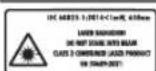
Laser radiation
Do not stare into the beam
Consumer laser product of Class 2
EN 50689:2021

Do not place the device in the vicinity of the device while the power tool is working. There is a risk of injury from the laser beam.

Work with protective goggles.
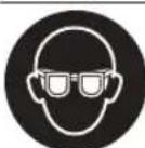
Work with protective gloves.
Symbols and their meaning

Hearing protection. The noise level may cause hearing loss.

Danger zone! Keep hands and fingers at a distance from this zone.

When carrying the power tool, hold it only by the marked places (handles) or by the carrying handle.
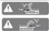
Before tilting the saw head to a vertical position, the adjustable support foot must be pulled out. It must be demonstrated.
3601M511.. 254mm 3mm
3601M511B. 3601M5118.
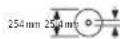
Assemble according to the dimensions of the circular saw blade. The hole must pass without play over the spindle of the saw. If it is necessary to use reducing rings, check the dimensions of the reducing rings to fit the blade hole, the diameter of the hole, as well as the diameter of the machine spindle. Possibility to use reducing rings, included in the circular saw blade set.
The diameter of the circular saw blade must correspond to the specified symbol above.
Product description and performance

Read carefully all safety instructions. Failure to follow the safety instructions and the operating instructions may result in electric shock, fire and/or serious injury.
Keep all safety instructions and operating instructions for future reference.
Intended use of the power tool
The power tool is intended for making straight and miter cuts in wood materials, mounted stationary on a workbench. It is possible to make horizontal miter cuts from -48° to +48° as well as vertical miter cuts from 47° (left) to 47° (right).
The power tool is designed for cutting solid wood materials, as well as for cutting grooves and rebates.
Using suitable circular saw blades, it is also possible to cut aluminum profiles and plastic.
This product is a consumer laser product in accordance with EN 50689.
Illustrated components
The numbering of the components refers to the illustration of the power tool on the front page.
(1) Locking knob for the miter saw (2) Miter saw (3) Handle for carrying (4) Protective guard (5) Lockable switch (6) Switch lock (7) Handle (8) Laser guide (9) Opening for laser beam (10) Protective guard for the saw blade (11) Roller (12) Saw blade (13) Mounting holes (14) Base plate (15) Fixing bracket (16) Locking handle for bevel angle adjustment (horizontal) (17) Bevel angle adjustment (horizontal) (18) Protection against kickback (19) Warning label for laser (20) Locking knob for bevel angle adjustment (horizontal) (21) Scale for bevel angle (horizontal) (22) Locking knob for saw blade guard (23) Saw blade guard (24) Saw blade (25) Fixed support (26) Adjustable support (27) Scale for bevel angle (vertical) (28) Bevel angle indicator (vertical) (29) Protective plate (30) Receiver (31) Locking knob (32) Button for disconnecting the battery pack
308|Bulgarian
(33) Battery pack (34) Transport safety (35) Support bracket (36) Depth stop (37) Dust extraction adapter (38) Adjusting knob for depth stop (39) Depth stop (40) Wrench (41) Screw clamp (42) Holes for screws (43) Hex key/screwdriver (44) Fixing screw for adjusting the support (45) Locking lever for bevel angle (vertical) (46) Locking knob for bevel angle (vertical) (47) Support for workpiece (on the power tool)
(48) Support for second workpiece (on the support) (49) Consumption (50) Dust extraction adapter (51) Screw with internal hex for clamping the saw blade (52) Locking flange (53) Inner locking flange (54) Screws for base plate (55) Screw for laser guard (56) Locking screw for laser housing (57) Laser housing (58) Bevel angle indicator (horizontal) (59) Screw for bevel angle indicator (horizontal) (60) Screw for bevel angle indicator (vertical) (61) Holes for extraction
Technical data
| Актуларов по палейten Трон GCM 18V-254 D GCM 18V-254 D | ||
| Каталожен Home | 3601 M51 1... 3601 M51 1B. | |
| 3601 M51 18. | ||
| Номинално наразжения V = 18 18 | ||
| Овороти на праzenхов“A) | min -1 | 4500 4500 |
| Ти пазерnm 650 650 | ||
| mW < 1 < 1 | ||
| Клас пазер 2 2 | ||
| ТergоB) | kg 17,7-18,7 17,7-18,7 | |
| Прелорчтелна темпера typа на okолнatable creда наразожданe | °C 0 ... +35 0 ... +35 | |
| Разецна темпера typа на okолнatable creда наразotingC) и на скадиранe | °C -20 ... +50 -20 ... +50 | |
| Прелорчтелны akумалatorни бateрни GBA 18V... | GBA 18V... | |
| ProCORE18V... | ||
| Прелорчтелны заюн устрий CTBA GAL 18... | GAL 18... | |
| GAX 18... | ||
| GAL 36... | ||
| Разmersи на podхodшни чиркульникни дисковe | ||
| Диаметр на цируняпни дисс | mm 254 254 | |
| Дебенина на талOTO на диска | mm | 1,4-2,5 |
| Диаметр на отвора на дисca | mm 30 | 25,4 |
A) Measured at 20-25°C with battery pack ProCORE18V 8.0Ah. B) Depending on the battery pack used. C) Limited power at temperatures below 0°C. The values may vary depending on the project and the working environment. More information at www.bosch-professional.com/wac. Permissible workpiece dimensions (max/min): (see "Permissible workpiece dimensions", page 315
Information about noise
The noise values have been determined in accordance with EN IEC 62841-3-9.
The typical A-weighted noise level of the power tool is: sound pressure level 97 dB(A); sound power level 106 dB(A). Uncertainty K = 3 dB.
Wear ear protection!
Instructions for use, safety warnings, and measurement procedures are described in the standard methods. The comparison is made on different electronic instruments. The evaluation of the measurement uncertainty is performed.
The instructions for use are representative and are based on the application of the electronic instrument. If the electronic instrument is used under different conditions, the comparison of the instrument's performance may not be reliable. The measurement uncertainty may vary. This could significantly increase the measurement uncertainty over the period of use of the electronic instrument.
For proper use, the user must read the periods during which the electronic instrument is switched off or operated in idle mode. This could significantly reduce the measurement uncertainty over the period of use of the electronic instrument.
Battery pack
Bosch sells electronic instruments without a battery pack. For details on the delivery scope of your electronic instrument, refer to the packaging.
Charging the battery pack
Use only the chargers listed in the technical data section. These chargers are suitable for the lithium-ion battery pack used in your electronic instrument.
Note: Lithium-ion battery packs are delivered partially charged according to international transport regulations. To ensure full battery capacity, fully charge the battery pack before first use.
Inserting the battery pack
Insert the charged battery pack into the battery slot until it clicks into place.
Removing the battery pack
To remove the battery pack, press the release button and pull out the battery pack. Do not use force.
The battery pack has two locking levels to prevent the battery from falling out due to unintentional pressing of the release button. When the battery pack is inserted into the electronic instrument, it locks into the correct position automatically.
Battery charge indicator
Note: Not every battery pack has a charge status indicator.
The LED indicator for the battery pack shows the charge level of the battery pack. For safety reasons, checking the charge level is only possible when the power tool is switched off.
To display the charge level of the battery, press the button for the charge level indicator. It is also possible to do this when the battery pack is removed.
If the charge level indicator does not light up after pressing the button, the battery pack is defective and must be replaced.
Battery pack 18V...

Charge level indicator
Continuous lighting 3×green 60-100%
Continuous lighting 2×green 30-60%
Continuous lighting 1×green 5-30%
Flashing light 1×green 0-5%
Battery pack ProCORE18V...

Charge level indicator
Continuous lighting 5×green 80-100%
Continuous lighting 4×green 60-80%
Continuous lighting 3×green 40-60%
Continuous lighting 2×green 20-40%
Light color 1 × green 5-20%
Low light 1×green 0-5%
Instructions for optimal operation of the battery
Charge the battery in a dry and clean place. Store the battery at temperatures between -20°C and 50°C. For example, do not leave the battery in a car during summer in the sun.
Periodically check the ventilation openings of the battery and keep them clean and dry.
Significantly reduced operating time after charging indicates that the battery is worn out and must be replaced.
Follow the disposal instructions.
Mounting
Before performing any work on the power tool (e.g., maintenance, changing the working tool, etc.), when transporting or storing, remove the battery. There is a risk of injury when starting the switch accidentally.
Package contents

Mount, see the illustration of the package contents at the beginning of the operating instructions.
Before starting the power tool, check that all listed items are included:
- Battery pack (45) - Charger (45) - Adjustable support leg (26) - Screwdriver bit (41) - Hex key/right angle screwdriver (43) - Dust bag (37) - Sanding sheets (24) (2 pcs.)
Note: Check the power tool for possible damage.
Before using the power tool, carefully check that the protective devices and any slightly damaged parts function correctly as intended. Check that the moving parts function correctly and are not jammed, and that no parts are damaged.
Before use, the tool must be installed correctly and all conditions for safe operation must be met.
Damaged or worn parts must be repaired or replaced by qualified personnel at an authorized service center for power tools.
Installing accessories
Carefully read all instructions included in the package. Remove all packaging materials from the power tool and accessories included in the package. To facilitate installation of the accessories included in the package, the power tool must be in the transport position.
Installing the support for workpieces (see Fig. A1)
The supports for workpieces (24) can be positioned in two ways, depending on the requirements of the power tool. The clamping system allows a variety of adjustment options (see Fig. F). - Loosen the screws for the support for workpieces (24), place them in the holders (47) on the power tool or in the holders (48) on the second support for workpieces.
Never carry the power tool by the supports for workpieces. Use only the transport handles when transporting the power tool.
Never carry the power tool by the supports for workpieces. Use only the transport handles when transporting the power tool.
Installing the locking knob (see Fig. A2)
The locking knob (45) is fixed to the vertical adjustment and is necessary for safe operation.
- Loosen the locking knob (45) by turning it counterclockwise. - Tighten the locking knob (45) by turning it clockwise.
Installing the adjustable stop rail (see Fig. A3)
The adjustable stop rail (26) must be installed before use. - Slide the stop rail (26) onto the circular saw blade guard. The front part of the stop rail must point towards the circular saw blade.
Stationary and mobile installation
To ensure safe operation with the power tool, before using it, you must mount it on a flat and stable work surface (e.g., workbench).
Mounting on a work surface (see Fig. B1-B2)
-Mounting the power tool with the supplied screws onto the work surface. Tighten the screws (13).
NOTICE - Mounting the power tool with the supplied screws and brackets, as shown, by gripping the brackets to the work surface.
Mounting on a wall (see Fig. B3)
Wall mounting: Ensure that the power tool is securely attached to any surface. Adjust the height of the brackets. The surfaces for the wall mounting brackets must be suitable for supporting the weight of the tool.
Read all safety warnings and instructions supplied with the tool. Failure to follow the warnings and instructions may result in electric shock, fire and/or serious injury. Before mounting the power tool, ensure that the wall is stable and level. Proper mounting of the tool is important to avoid the risk of it falling during operation. -Mount the power tool to the wall while it is in the transport position.
Stable placement (not tipping over!) (see Fig. B3)
If it is not possible to mount the power tool on a flat, stable work surface, you can place it on the floor using the support leg.
Without the support leg, the power tool is not stable, especially when cutting at maximum possible horizontal or vertical angles. There is a risk of tipping over. -Extend the support leg (18) until the power tool is stable on the work surface.
Dust extraction system
Dust from materials such as lead-based paint, some wood types, minerals and metals can be harmful to health. Contact with or inhalation of these dusts can cause allergic reactions and/or respiratory diseases. Always work with the power tool connected to a suitable dust extraction system.
Certain dusts, e.g. those produced when working with beech or oak, are considered carcinogenic, especially in combination with wood treatment additives (chromate, wood preservatives, etc.). Only allow asbestos-containing materials to be worked on by suitably qualified personnel.
-If possible, use a dust extraction system suitable for the material being worked on. -Ensure good ventilation of the work area. -It is recommended to use a breathing mask with filter class P2.
Observe the relevant regulations in your country for the materials being worked on. -Prevent dust accumulation at the work area.
Dust can easily ignite.
Dust extraction for safe operation, protection against dust.
- Remove the electric tool and the battery from the dust extraction unit. - Check that the dust extraction unit is clean. - Open and empty the dust collection container.
Self-generated dust extraction (see Fig. C)
For dust-free operation, also collect the resulting dust using the dust extraction hose included in the delivery (37).
- Adjust the transport handle (3) vertically. - Insert and turn the dust extraction hose (37) into the dust extraction outlet (50) so that the dust extraction hose is secured in the dust extraction outlet.
During operation, the dust extraction hose must not come into contact with moving parts of the electric tool.
Empty the dust extraction hose regularly.
Check and clean the dust extraction hose after each use. To prevent fire hazards, clean the dust extraction hose after vacuuming aluminum alloys.
External dust extraction
For vacuuming, you can attach a vacuum cleaner hose (Ø 35 mm) to the dust extraction outlet (50).
- Attach the vacuum cleaner hose to the dust extraction outlet (50).
The vacuum cleaner used must be suitable for working with the material being processed.
If, during operation, particularly long periods of dust extraction or carcinogenic dust are produced, use a specially designed vacuum cleaner.
Changing and adjusting the sanding disc (see Fig. D1–D4)
Before performing any work on the electric tool (e.g., maintenance, changing the tool, etc.), remove the battery from the electric tool. There is a risk of injury if the start switch is accidentally activated. When changing the sanding disc, wear protective gloves. When using the sanding disc, there is a risk of injury.
Use only flat discs, as the maximum permissible speed of the flat discs is higher than the speed of the flat discs and the correct operation of your power tool. Use only flat discs that correspond to and are marked in this manual for operation of the given discs and are marked according to EN 847-1 and marked accordingly.
Use only discs that are recommended by the manufacturer of the power tool for the material you are working on. This prevents overloading of the teeth during cutting.
Removing the circular saw blade
- Place the power tool in the working position. - Tilt the protective guard (10) back and lock it in this position. - Tighten the screw with the hexagon socket (51) with the hexagon key (6 mm) (43) while simultaneously pressing the spindle lock (31) until it engages. - Tighten the locking bolt for the spindle (31) by pressing and turning the screw (51) clockwise (right-hand thread!). - Remove the flange (52). - Remove the circular saw blade (30). - Slowly return the protective guard to its original position.
312|Bulgarian
Mounting the circular saw blade
When mounting, pay attention to the direction of rotation of the teeth (marked with an arrow on the circular saw blade) to match the direction of the arrow on the protective guard!
If necessary, clean all parts that are to be mounted.
- Tilt the hinged protective guard (10) back and lock it in this position. - Place the new circular saw blade on the inner flange (53). - Mount the flange (52) and the screw with the hexagon socket (51). Press the spindle lock (31) until the spindle engages, and then tighten the hexagon socket screw clockwise. - Slowly return the hinged protective guard to its original position.
Working with the power tool
Before performing any work on the power tool (e.g., maintenance, changing the working tool, etc.), when transporting or storing it, remove the battery.
There is a risk of injury from unintentional starting.
Transport safety (see figure E)
The transport safety device (34) secures the power tool in different working positions.
Releasing the power tool (working position)
- Turn the power tool off before carrying out adjustments, changing accessories, or storing the tool. - Select the correct insert tool for the application. - Secure the workpiece before transporting it.
Power tool cover (transport position)
- Loosen the screw (1) if the locking mechanism for the adjustment (2) is blocked. Remove the battery from the power tool.
Removing the dust extraction adapter (see figure H)
When cutting at an angle, the horizontal and/or vertical cutting angle must be adjusted according to the cutting direction. To do this, tilt the saw head to the left or right, or adjust the miter angle (26).
45° (left) 45° (left) 55 x 215
45° (left) 45° (left) 30 x 215
- Mount the tool securely on a stable surface without the possibility of tipping over. - Use of circular saw blades with appropriate specifications. - Regular maintenance of the circular saw and the power tool.
Customer service and application consulting
Our after-sales service responds to your questions concerning maintenance and repair of your product, as well as spare parts. Exploded views and information on spare parts can be found at:
www.bosch-pt.com
The Bosch application consulting team will be happy to help you with any questions about our products and their accessories.
Please, when ordering spare parts, always quote the 10-digit article number given on the type plate of the product.
Bulgaria
Robert Bosch SRL
Electric power tools service
Strada Horia Macelariu Nr. 30-34, sector 1
013937 Bucharest, Romania
Tel.: +359(0)700 13667 (Bulgarian)
Fax: +40 212 331 313
Email: BoschServiceCenterBG@ro.bosch.com
www.bosch-pt.com/bg/bg/
Other service addresses can be found at:
www.bosch-pt.com/serviceaddresses
Transport
The contained lithium-ion batteries are subject to the Dangerous Goods Legislation requirements. The batteries can be transported by road without further restrictions.
When transporting by third parties (e.g., by air transport or forwarding agency), special requirements on packaging and labelling must be observed. For preparation of the item being shipped, consulting an expert for hazardous material is required.
Dispatch the battery only if the housing is undamaged. Tape or mask off open contacts and pack up the battery such that it cannot move around in the packaging. Please also observe the possibility of more detailed national regulations.
Disposal

Electric tools, batteries, accessories and packaging should be sorted for environmental-friendly recycling.
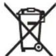
The 3XbBpNJIe eNeKTPoINHCTpyMeHTn akyMnyatopHN INN O6NKHOBeHN 6aTePNn npn 6nTOBNTe Otnabu!
Page from EC:
According to European Directive 2012/19/EC on waste electrical and electronic equipment (WEEE) and its transposition into national law, electrical and electronic equipment that can no longer be used must be collected separately. According to European Directive 2006/66/EC, damaged or used batteries and accumulators must be collected and handed in for recycling of the substances contained in them.
Improper disposal of old electrical and electronic equipment may have harmful effects on the environment and human health due to the potentially hazardous substances contained in them.
Batteries and accumulators:
Lithium-ion:
Please follow the instructions in the transport section (see "Transport", page 317).
Macedonian
Safety instructions
The device has been tested for electrical safety
WARNING
CAUTION
Read all safety instructions, illustrations and specifications supplied with this device.
Failure to follow the instructions supplied with the device may result in electric shock, fire and/or serious injury.
Keep all safety instructions for future use and for other users.
Warning! The electrical appliance is designed to be connected to the mains (cable) or to a battery (rechargeable).
Workplace safety
Keep your workplace clean and well lit. Cluttered or dark areas can lead to accidents. Do not operate electrical appliances in explosive atmospheres, such as in the presence of flammable liquids, gases, or dust. Electrical appliances create sparks that can ignite dust or fumes. Keep children and bystanders away while operating an electrical appliance. Distractions can cause you to lose control.
Electrical safety
The plug of the electrical appliance must match the outlet. Never modify the plug. Do not use adapter plugs with grounded electrical appliances. Unmodified plugs and matching outlets reduce the risk of electric shock. Avoid body contact with grounded surfaces, such as pipes, radiators, metal cabinets, and refrigerators. There is an increased risk of electric shock if your body is grounded. Do not expose electrical appliances to rain or wet conditions. If water enters the electrical appliance, the risk of electric shock increases. Do not misuse the cord. Never use the cord for carrying, pulling, or unplugging the electrical appliance. Keep the cord away from heat, oil, sharp edges, or moving parts. Damaged or tangled cords increase the risk of electric shock. When operating an electrical appliance outdoors, use an extension cord suitable for outdoor use. Using a cord suitable for outdoor use reduces the risk of electric shock. If you must operate an electrical appliance in a damp location, use a residual current device (RCD) protected supply. The use of an RCD reduces the risk of electric shock.
Personal safety
Stay alert, watch what you are doing, and use common sense when operating an electrical appliance. Do not use an electrical appliance while you are tired or under the influence of drugs, alcohol, or medication. A moment of inattention while operating electrical appliances may result in serious personal injury. Use personal protective equipment. Always wear eye protection. Protective equipment such as a dust mask, non-skid safety shoes, hard hat, or hearing protection used for appropriate conditions will reduce personal injuries. Prevent unintentional starting. Ensure the switch is in the off position before connecting to the power source and/or battery pack, picking up, or carrying the appliance. Carrying electrical appliances with your finger on the switch or energizing electrical appliances that have the switch on invites accidents.
Pay attention to how you work with power tools. Do not use power tools if you are tired or under the influence of alcohol, drugs, or medication. A moment of inattention while working with power tools can lead to serious personal injury. Use personal protective equipment. Always wear eye protection. Protective equipment such as a dust mask, non-slip safety shoes, hard hat, or hearing protection used for appropriate conditions will reduce personal injuries. Prevent unintentional starting. Ensure the switch is in the off position before connecting to the power source and/or battery pack, picking up or carrying the tool. Carrying power tools with your finger on the switch or energizing power tools that have the switch on invites accidents.
The power tool plug must be connected to the power outlet only in the way specified in the instructions. The plug or the outlet must be suitable for the power tool. Improper use may lead to injury. Do not bypass the safety devices. Always maintain the correct posture and balance. This ensures better control of the power tool in unexpected situations. Dress properly. Do not wear loose clothing or jewelry. Keep your hair and clothing away from moving parts. Loose clothes, jewelry, or long hair can get caught in moving parts. If devices are provided for the connection of dust extraction and collection facilities, ensure these are connected and properly used. Use of dust collection can reduce dust-related hazards. Do not let familiarity gained from frequent use of the tool allow you to become complacent and ignore tool safety principles. A careless action can cause severe injury within a fraction of a second.
Use and care of power tools
Do not force the power tool. Use the correct power tool for your application. The correct power tool will do the job better and safer at the rate for which it was designed. Do not use the power tool if the switch does not turn it on and off. Any power tool that cannot be controlled with the switch is dangerous and must be repaired. Disconnect the plug from the power source and/or remove the battery pack, if detachable, from the power tool before making any adjustments, changing accessories, or storing power tools. Such preventive safety measures reduce the risk of starting the power tool accidentally. Store idle power tools out of the reach of children and do not allow persons unfamiliar with the power tool or these instructions to operate the power tool. Power tools are dangerous in the hands of untrained users. Maintain power tools and accessories. Check for misalignment or binding of moving parts, breakage of parts and any other condition that may affect the power tool's operation. If damaged, have the power tool repaired before use. Many accidents are caused by poorly maintained power tools.
Keep cutting tools sharp and clean. Properly maintained cutting tools with sharp cutting edges are less likely to bind and are easier to control. Use the power tool, accessories and tool bits etc. in accordance with these instructions, taking into account the working conditions and the work to be performed. Use of the power tool for operations different from those intended could result in a hazardous situation. Keep handles and grasping surfaces dry, clean and free from oil and grease. Slippery handles and grasping surfaces do not allow for safe handling and control of the tool in unexpected situations.
Use of battery-operated tool
If the battery is not used properly, it may cause a fire hazard. The battery is intended for use only with the specified device. Using the battery with other devices may cause damage or fire. When not using the battery, keep it away from other metal objects such as paper clips, coins, keys, nails, screws, or other small metal objects that can create a connection from one terminal to another. Shorting the battery terminals may cause burns or fire. Under extreme conditions, liquid may leak from the battery; avoid contact. If accidental contact occurs, flush with water. If liquid gets into eyes, seek medical help immediately. Liquid leaked from the battery may cause irritation or burns. Do not use the battery or device if it is damaged or modified. Damaged or modified batteries may behave unpredictably and may cause fire, explosion, or risk of injury. Do not expose the battery or device to fire or excessive temperature. Exposure to fire or temperature above 130°C may cause explosion. Follow all instructions for charging and do not charge the battery or device outside the temperature range specified in the instructions. Charging improperly or at temperatures outside the specified range may damage the battery and increase the risk of fire.
Service
Have the electrical device serviced by a qualified repair person using only identical replacement parts. This will ensure that the safety of the electrical device is maintained.
Never repair damaged battery packs. Battery pack repair should only be carried out by the manufacturer or authorized service providers.
Safety warnings for all devices
Abrasive cutting wheels for cutting metal cannot be used with abrasive discs for cutting other metals, such as sheet metal, pipes, profiles, etc. The abrasive cutting wheel requires the workpiece to be clamped, as is the case with a bench grinder. The sparks from abrasive cutting are directed at the full thickness, cutting the sheet metal parts. Use the guard for the workpiece that is being processed whenever possible. If you are processing the workpiece by hand, the guard must always be at a distance of at least 100 mm from both sides of the cutting disc. Do not use this disc for cutting workpieces that cannot be safely clamped or held by hand. If you place the guard in front of the disc, there is a great danger of injury if you push the workpiece. The workpiece must be stationary and clamped, or held by the edges and the mass. Do not place the workpiece in the cutting area or in the path of the disc. A loose or unclamped workpiece can be thrown at high speed and cause injury. Keep your hands away from the workpiece. Do not reach under the workpiece. To cut, lower the disc head onto the workpiece and push it through without cutting, turn on the motor, lower the disc head onto the workpiece, and push it through. By lowering the disc, the cutting action can cause the disc to jump on the edge of the workpiece and throw it towards the operator. Do not work on a curved cutting line before and after the cut. Working on the workpiece with the disc, i.e., working on the right side of the disc with the left hand, is extremely dangerous. Do not reach for the guard at a distance of more than 100 mm from both sides of the cutting area to remove wood chips or other debris while the disc is rotating. You may not notice the disc approaching your hand and you could be seriously injured. Examine the workpiece before starting to cut. If the workpiece is bent or warped, clamp the convex side against the guard. Always check for clearance between the workpiece, the guard, and the table surface along the cutting line. Bent or warped
The workpiece can be thrown or displaced, causing the cutting disc to break. There must be no nails or other foreign objects in the workpiece.
If the workpiece is properly secured and the cutting disc is correctly mounted, the remaining material can be removed at high speed. Only one piece should be cut at a time. The workpiece can be clamped or held securely during cutting. Check that the cutting disc is not mounted or placed on the frame, and that the work area is clear before use. The frame and work area reduce the risk of the cutting disc becoming unstable. Always wear protective equipment. When changing the cutting disc or the guard, check that the guard is correctly positioned to protect the operator and that it does not obstruct the cutting disc or the safety devices. Without switching on the "ON" switch, the cutting disc should be rotated manually to check that it does not touch the guard or any other part. Ensure proper support, such as additional supports, stands, or similar, for the workpiece being cut, especially if it is long or heavy. If the workpiece being cut is long, it may need additional support to prevent it from tipping over. If the workpiece is not properly supported, it may tip over and cause injury. Do not use the tool as a substitute for a table saw or as an auxiliary table. Improper support of the workpiece can cause the cutting disc to bind or the workpiece to be thrown during cutting, which could injure you or the helper. The workpiece must not be held or pressed against the cutting disc. If the workpiece is limited, i.e., with the help of length stops, the cut-off piece can be held or removed. Always use the correct clamping or fastening device for holding the material, such as clamps or vises. The clamps tend to loosen while cutting, so check and tighten them as needed. Keep your hands away from the cutting area and do not reach under the workpiece. Let the cutting disc reach full speed before starting the cut. With this
method, the risk of the workpiece being thrown is reduced.
If the tool is being used, make sure to hold it firmly. Wait for all moving parts to stop and unplug the tool from the mains and/or remove the battery pack. Then remove the jammed material. If you continue to work with a jammed tool, you may lose control and cause injury. When you have finished sawing, release the switch, keep your head away from the saw blade, and wait for the saw to stop before you put down the saw. Retracting the saw blade while it is still rotating is dangerous. Hold the saw firmly when making a plunge cut or when releasing the switch before the blade is fully lowered into the saw kerf. The saw base may cause the saw blade to be lifted unexpectedly, raising the blade and causing a hazard or injury. Do not operate the saw if the saw blade has reached the lowest position. Always retract the saw blade to the highest position. If the saw blade is uncontrolled, it may cause injury. Keep the work area clean. Material debris is especially dangerous. Dust from cutting metal can be explosive. Do not use dull, cracked, bent, or damaged blades. Blades with dull or incorrect teeth cause excessive friction, causing overheating and binding of the blade or kickback. Do not use blades for high-speed steel (HSS) cutting. Such blades can easily break. Always use blades with the correct hole shape (round or diamond) for the arbor. Blades that do not fit the mounting parts of the saw will run off center, causing loss of control. Never place the remaining part of the workpiece on the saw table while the electric tool is switched on. First place the saw on the workpiece in the cutting position and then switch on the electric tool. Do not place the saw on the workpiece after finishing work until it has stopped. The saw blade for work is switched on. Improper use of the battery may cause a fire. The battery may ignite or explode.
If the battery is damaged, take it to a specialist. The battery may cause a fire or explosion.
Do not open the battery. There is a risk of short circuit. The battery can be damaged by sharp objects such as nails or screwdrivers or by impact. This can cause an internal short circuit, and the battery may ignite, emit smoke, explode, or overheat. Use the battery only in the manufacturer's product. Only in this way will the battery be protected against dangerous overload.

Protect the battery from heat, e.g., from continuous intense sunlight, fire, dirt, water, and moisture. There is a risk of explosion and short circuit.
Electrical shock hazard. Follow the warning signs for laser (see table, warning signs meaning). If the text of the laser warning sign is not in your language, affix the label in your language before first use. Do not remove the laser warning sign.

Do not stare into the laser beam, whether directly or indirectly. You may damage your eyes or cause blindness. Always avoid direct eye exposure to the laser beam.
After the laser beam is switched off, you must close the shutter and remove the key from the laser. Do not make any modifications to the laser. The functions described in this user manual can be used without restrictions. Do not leave the electrical device unattended. Without supervision, it may cause accidents or damage.
Symbols
The following symbols are of great importance for the use of your electrical device. You should familiarize yourself with the meaning of the symbols. The correct interpretation of the symbols will help you to use the electrical device safely and efficiently.
Symbols and their meanings
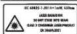
Laser beam: Do not look into the beam, class 2 laser product
Symbols and their meanings
EN 50689:2021

Do not point the device at the sun or in the direction of the sun. When the device comes into contact with the sun's rays, there is a risk of damage.

(58) Laser aperture (horizontal)
(60) Laser aperture (vertical)
(61) Key switch
Technical data
Battery pack for GCM 18V-254 D GCM 18V-254 D
| Б Proj на哪儿 | 3 601 M51 1... | 3 601 M51 1B. |
| 3 601 M51 18. | ||
| Номинален наюн V= 18 18 | ||
| Б Proj на вртыхи во паазен odA) | min-1 | 4500 4500 |
| Тип на ласерnm 650 650 | ||
| mW < 1 < 1 | ||
| Класа на ласер 2 2 | ||
| Текинab) | kg 17,7-18,7 17,7-18,7 | |
| Преторачана okолна Temпера typа ррипогоньe | °C 0 ... +35 0 ... +35 | |
| Дозвoleна okолна Temпера typa рри работа c) и рри скадралье | °C -20 ... +50 -20 ... +50 | |
| Преторачаны akumу latорсki батерни GBA 18V... | ProCORE18V... | GBA 18V... |
| ProCORE18V... | ||
| Преторачаны погради GAL 18... | GAL 18... | |
| GAX 18... | GAX 18... | |
| GAL 36... | GAL 36... |
Hmeh3nn 3a COoBETn CeuHa 3a Hnla
TpaJno CBeTIO 3×3eIeHO 60-100%
TpaJno CBeTnO 2×3eNeHo 30-60%
TpaJHo CBeTno 1×3eNeHo5-30%
TpENKaBO CBeTNo 1×3eNeHo 0-5%
Tin ha 6atepnja ProCORE18V...


LED-cbETmKn KanaunTet
TpaJno CBeTNO 5×3eIeH0 80-100%
TpaJHo CBeTno 4×3eNeHo 60-80%
TpajnoCBetno 3× 3eNo40-60%
TpaJno CBeTnO 2× 3 eNo 20-40%
LED-cBetnKn KanaHTET
TpaJHo CBeTnO 1×3eNeHO5-20%
TpENKABO CBeTNo 1×3eNo 0-5%
HanomeHH 3a ONTHMaHNO KOpHCTeBe Ha 6aTePnHTe
Remove the battery from the device.
Store the battery in a dry place at a temperature between -20°C and 50°C. Do not leave the battery in a car in summer.
Open the ventilation openings of the battery with a cloth, then wipe it dry.
Short operating time after charging indicates that the battery is worn out and must be replaced. Pay attention to the warning about disposal.
Assembly
Before any intervention on the electric tool (e.g., cleaning, replacing parts, etc.) as well as its transport and storage, remove the battery from it. Inadvertent activation of the switch for switching on/off poses a risk of injury.
Volume of delivery
Therefore, pay attention to the display of the delivery volume at the beginning of the section for use.

Before first use of the electric tool, check that all listed parts are included:
- Saw blade for cutting with mounted saw blade - Scraper (45) - Adjustable guide roller (26) - Carpenter's square (41) - Hex key for the saw blade clamping screw (43) - Wrench (37) - Basic attachment for processing (24) (spare)
Note: Check that the electric tool has a protective guard.
Before using the electric tool, you must check the protective devices and parts that can be easily damaged to ensure they function correctly. Check that the moving parts function properly and are not jammed, and that the parts are not damaged. All parts must be correctly mounted and all conditions met to ensure safe operation.
Damaged protective devices and parts must be repaired or replaced by an authorized service workshop.
Assembly of the supplied parts
- Check the power tool and the accessories for damage before each use. - Make sure the power tool is disconnected from the power supply and from the accessories before any adjustment. - To ensure safe operation, during assembly pay attention to the correct parts of the device, especially the electrical parts and the transport position.
Mounting the base of the workbench (see figure A1)
The base of the workbench (24) can be adjusted left, right, or to the front of the electrical tool. The clamping system allows for different options for extension and adjustment (see figure G).
- To use, insert the base of the workbench (24) into the guides (47) of the electrical tool and into the guides (48) of the second base of the workbench. Never carry the electrical tool by the bases of the workbench. For transporting the electrical tool, always use the transport handles.
Mounting the tensioning strap (see figure A2)
The tensioning strap (45) is fixed to the vertical column of the lifting mechanism and is required for safe operation.
- Make sure the length of the strap is correct, adjust the buckle (49). - Thread the tensioning strap (45) in the direction of the arrows of the buckle (49) and tighten it.
Mounting the guide rail (see figure A3)
The guide rail (26) must be mounted before use.
- Insert the guide rail (26) to the right of the saw blade into the appropriate slot and tighten the screw for locking. The straight part of the guide rail must be aligned with the saw blade.
Fixed or flexible mounting
To enable safe handling, the electrical tool must be mounted before use on a stable work surface (e.g., a workbench).
Mounting the work surface (see figures B1-B2)
- Screw the electrical tool with the appropriate screws to the work surface. For this purpose, use the holes (13). Or - Screw the electrical tool with the standard screws of the work surface.
Mounting the work table of the saw
The power tool is intended for sawing wood, plastic, and similar materials. It is not suitable for cutting metal. Follow the instructions for proper use of the tool.
Read all safety warnings and instructions. Failure to follow the warnings and instructions may result in electric shock, fire, and/or serious injury. Mount the saw blade correctly before connecting the power tool. The correct mounting is important to avoid the risk of kickback. Mount the saw blade in the transport position of the power tool.
Fixed installation (not recommended!) (See figure B3)
If, in exceptional cases, it is not possible to mount the power tool in the fixed installation position, it may be temporarily supplied with anti-tip protection.
Without anti-tip protection, the power tool is not stable and may tip over when cutting at maximum horizontal and/or vertical bevel angles.
Ensure that the anti-tip protection (18) is on the inside or outside before the power tool is placed on the work surface.
Dust extraction
Dust from materials such as lead-based paint, some wood types, minerals, and metals can be harmful to health. Contact with or inhalation of such dust can cause allergic reactions and/or respiratory diseases in the user or bystanders.
Certain types of dust, such as oak and beech dust, are carcinogenic, especially when combined with additional substances (chrome, wood preservatives). Materials containing asbestos should only be processed by qualified personnel.
Therefore, whenever possible, use a suitable dust extraction system for the material being processed. Ensure good ventilation of the work area. It is recommended to wear a dust mask with filter class P2.
Observe the relevant regulations in your country for the materials being processed.
Avoid accumulation of dust at the work area. Dust can easily ignite.
Dust extraction can be blocked by dust, shavings, or debris from the workpiece.
Switch on the power tool and wait until the blade reaches full speed. Open the dust extraction flap and remove it.
Self-extraction (See Figure C)
Place the tool holder so that the cutting tool is correctly positioned for right-hand cutting (37). -Position the transport bracket (3) vertically. -Press and turn so that the tool holder (37) fits into the suction hose (50), so that the tool holder is inserted into the suction hose.
During cutting, the tool holder must never come into contact with the workpiece.
Regularly clean the tool holder.
Check and inspect the tool holder after each use. To avoid fire hazards, when cutting aluminum, remove the tool holder.
Suction
For suction, you can attach the suction hose (50) to the suction adapter (Ø 35 mm). -Connect the suction hose to the suction adapter.
The suction device must be suitable for the material being processed.
When suctioning particularly hazardous dust, carcinogenic or toxic dust, use a suitable suction device.
Replacing the saw blade (see Figures D1-D4)
Before any work on the electric tool (e.g., maintenance, blade change, etc.) and during transport or storage, remove the battery from the tool. Unintentional activation of the switch poses a risk of injury. Ensure that the saw blade is correctly mounted. If the saw blade is not mounted correctly, there is a risk of injury.
Use only saw blades whose maximum speed is higher than the rated speed of your electric tool.
Use only saw blades that meet the specifications in this instruction manual and have been tested according to EN 847-1 and are marked accordingly.
Use only saw blades recommended by the manufacturer and suitable for the electric tool and the material you want to cut. Such
Prevent overheating of the saw blade during cutting.
Positioning the guide rail (see Figure H)
Horizontal and vertical adjustment of the saw according to the workpiece, in order to obtain the best cut. Always remove the left side of the cutting table (26).
Adjustment of the workpiece for processing
Maximum workpiece dimensions:
| Xopns0htanen | Beptrkaneh aron | BucnHa x shpHnHa |
| arol Ha | Ha 3akocybahe | [mm] |
| 3akocybahe |
0° 0° 90 × 305
45° (left/right) 0° 90 × 215
45° (left) 45° (left) 55 × 215
Checking the basic settings
To ensure precise cuts, you must check the basic settings after intensive use of the electric tool and adjust them if necessary.
For this you need skill and the appropriate special tool.
The Bosch service department will do this work precisely and reliably.
Horizontal adjustment of the saw (see figure)
- Set the electric tool to the working position. - Loosen the locking screw (12) to the stop (20). For 0° the stop (17) must remain engaged in the stop.
Check
The pointer (58) must be in line with the 0° mark on the scale (21).
Adjustment
- Turn the knob (59) crosswise and center the arrow to the 0° mark. - Tighten the knob again.
Adjusting the arrow (vertical) (see figure V)
- Set the electric device to the working position. - Press the locking lever (45). - Pull out the locking pin (46) and set the vertical angle by turning the device with the hand to the 0° mark. The locking pin (46) must engage clearly in the recess. - Press the locking lever (45) again.
Check
The arrow (28) must be in one line with the 0° mark on the scale (27).
Transport
- Turn the knob (60) crosswise and center the arrow to the 0° mark. - Tighten the knob again.
Transport of the electric device (see figure W)
Before any intervention on the electric device (e.g., cleaning, replacing the device, etc.) as well as before its transport and storage, remove the battery from it. If you do not carefully read the instructions for switching on/off, there is a risk of injury.
For transporting the electric device, you must perform the following steps:
- Turn the locking knob (1) until it is tight. Pull out the device handle completely and then tighten the locking knob again. - Check that the depth stop (39) is set so that the locking knob (38) does not touch when the handle is lowered.
- Place the electric device in the transport position. - Remove the parts of the equipment that cannot be firmly mounted on the electric device. Put the loose parts for the saw in a closed box, as long as you want to transport them.
- Set the transport handle (3) vertically. - Carry the electric device with the transport handle (3) and hold it by the handles for carrying (61) on the side of the saw table. For transporting the electric device, use the transport equipment, not the handles or the base of the workbench.
Maintenance and service
Maintenance and cleaning
Check the mains connection of the electric tool (e.g., extension cable, replacement of the cable, etc.). If the tool is transported or stored, disconnect the battery from it. When disconnecting the plug from the socket, there is a risk of injury. Disconnect the mains plug and open the ventilation openings to ensure good ventilation before working.
The oscillating cutting blade must always be able to close freely and independently. The area around
The oscillating cutting blade must always be able to close freely.
Remove dust and debris by blowing with compressed air or using a brush after each work procedure.
Regularly clean the ventilation slots (11).
Measures for reducing dust
Measures for the product:
- Use a dust extraction system specifically designed for reducing dust.
Measures for the user:
- Work on a stable surface with minimal vibration - Use a dust extraction system with a dust reduction function - Regularly clean the dust extraction system and the electric tool
Service and customer advice
The service department will answer your questions regarding repairs and maintenance of your product as well as spare parts. Exploded views and information on spare parts can also be found at: www.bosch-pt.com
The Bosch customer advice team will help you if you have questions about your products and accessories. For all spare parts inquiries, you can find the 10-digit number from the type plate of the product.
North Macedonia
D.D. Enkovski
1000 Skopje
E-mail: dimce.dimcev@servis-bosch.mk
Internet: www.servis-bosch.mk
Tel./fax: 02/2467610
Mob: 070595888
D.I.T.Y "ROJKA"
Jane Krkovski 66; T.U Avtokomanda lokal 69
1000 Skopje
E-mail: servisrojka@yahoo.com
Tel: +389 2 3174-303
Mob: +389 70 388-520, -530
Additional service addresses can be found at:
www.bosch-pt.com/serviceaddresses
Transport
Lithium-ion batteries are subject to the Dangerous Goods Legislation requirements. The batteries can be transported by road without the need to comply with the special provisions.
332 | Serbian
When transporting by third parties (e.g. by air transport or forwarding agency), special requirements on packaging and labelling must be observed. For the preparation of the item being shipped, consulting an expert for hazardous material is required.
Transport the batteries only if the housing is not damaged. Tape off open contacts and pack up the battery in such a manner that it cannot move around in the packaging. Please also observe the possibly more detailed national regulations.
Disposal

Power tools, batteries, accessories and packaging should be sorted for environmentally-friendly recycling.
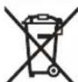
Do not dispose of power tools and batteries into household waste!
Only for EC countries:
According to the European Directive 2012/19/EU for waste electrical and electronic equipment and its implementation in national law, power tools that are no longer usable must be collected separately and disposed of in an environmentally correct manner. According to Directive 2006/66/EC, defective or used battery packs/batteries must be collected separately and disposed of in an environmentally correct manner.
If disposed of incorrectly, electrical and electronic equipment may have harmful effects on the environment and human health due to potentially hazardous substances.
Batteries:
Lithium-ion:
Please observe the notes in the section on transport (see "Transport", page 331).
Serbian
www.bosch-pt.com/serviceaddresses
Transport
Recommended lithium-ion batteries are subject to dangerous goods regulations. The user can transport the batteries by road without additional conditions.
When shipping via third parties (e.g., air transport or freight forwarding), special requirements regarding packaging and labeling must be observed. In such cases, a dangerous goods expert must be consulted when preparing the packages for shipment.
www.bosch-pt.com/serviceaddresses
Transport
www.bosch-pt.com/serviceaddresses
Transport
Recommended lithium-ion batteries are subject to dangerous goods regulations. The user can transport the batteries by road without any additional conditions.
If transport is carried out by a third party (e.g., air transport or freight forwarding), special requirements for packaging and labeling must be observed. When preparing such shipments for transport, a dangerous goods expert should be consulted beforehand.
Only ship the battery by any means of transport if its housing is undamaged. Tape over open contacts and pack the battery so that it cannot move around in the packaging. Also observe any additional national regulations.
Disposal

Power tools, batteries, accessories, and packaging should be brought to environmentally friendly recycling.
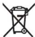
Do not dispose of power tools and batteries/rechargeable batteries in household waste!
Only for EU countries:
In accordance with the European Directive 2012/19/EU on waste electrical and electronic equipment and its implementation in national law, unusable power tools, and in accordance with the European Directive 2006/66/EC, defective or exhausted batteries/rechargeable batteries must be collected separately and brought to environmentally friendly recycling.
In case of improper disposal, electrical and electronic waste equipment may have harmful effects on the environment and human health due to the possible presence of hazardous substances.
Transport
Transport
The applicable regulations for the transport of dangerous goods apply to the lithium-ion batteries. The user can transport the batteries by road without further requirements.
When shipping them via third parties (e.g., by air transport or forwarding agency), special requirements regarding packaging and labeling must be observed. Therefore, a dangerous goods transport specialist must be consulted when preparing the shipment.
Only ship the battery if its housing is not damaged. Tape over open contacts and pack the battery in such a way that it cannot move around in the packaging. Please also observe any national regulations regarding battery transport, if applicable.
Transport
The regulations for the transport of dangerous goods apply to the lithium-ion batteries. The user can transport the batteries by road without further restrictions.
If shipping via third parties (e.g., by air transport or forwarding agency), special requirements for packaging and labeling must be observed. A dangerous goods transport specialist must be involved in preparing the shipment.
Only ship the battery if its housing is not damaged. Tape over open contacts and pack the battery in such a way that it cannot move around in the packaging. Please also observe any national regulations regarding battery transport, if applicable.
| LED | 용lage |
| ,enough 3× naked | 60-100% |
| ,enough 2× naked | 30-60% |
| ,enough 1× naked | 5-30% |
| 縫缕等 1× naked | 0-5% |
BabrLi RhipSc ProCORE18V...

LED speaker
[Battery] 20°C [50°C] [50°C] [50°C] [50°C] [50°C] [50°C] [50°C] [50°C] [50°C] [50°C] [50°C] [50°C] [50°C] [50°C] [50°C] [50°C] [50°C] [50°C] [50°C] [50°C] [Battery - 20°C [50°C] [50°C] [50°C] [50°C] [50°C] [50°C] [50°C] [50°C] [50°C] [50°C] [50°C] [50°C] [50°C] [50°C] [50°C] [50°C] [50°C] [50°C] [50°C]
External basic terms
EN847-1gJHepaRgeoDnO
www.bosch-pt.com/serviceaddresses
424
J 100
g d 100000000000000000000000000000000000000000000000000000
a
a 10000000000000000000000000000000000000000000000000000000000000
__SUPPIMER__
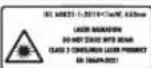

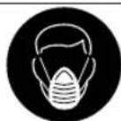



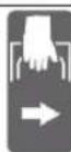
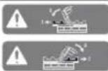
3601M511
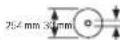
3601M511 B.
3601M511 8.
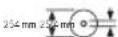
Aa 100
g kaoaag yolwll ldo aaydall L 1 L s g. aall gai j 1 gljag aall al uylk 1 duoig ojaai g adia 1 a
LgPdJl
psaalaa aaiall aagll
jolal jolal aLg Lg JnJnJnJnJnJnJnJnJnJnJnJnJnJnJnJnJnJnJnJnJnJnJnJnJnJnJnJnJnJnJnJnJnJnJnJnJnJnJnJnJnJnJnJnJnJnJnJnJnJnJnJn
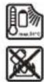
LdAaLdAaSaaal AaJg (44)
(45)
a gaaJgU
(lgac) bblglj cglj (46)
(a)UgJ≤J
()wIJwIaBg sinol
(JaiWl aobg sinw
LggsJg
EN 50689 standard
(1) (2) (3) Joiil Jado (4) 品良日 (5) Lob \ Lob . (6) LabyIg Jueuu z (7) (8)jjU|ooaUuU (9)jjuai aai gajadai (10) u→ 02 + u3 + u4 + u5 + u6 + u7 + u8 + u9 + u10 (11)aajjj (12)juiol xclg (13) (14) paliil aow (15) (16)agcJalllgl.
(17)(1
(18) (19)juiui (20)
428
aiaJI cuiJI
| GCM 18V-254 DGCM 18V-254 D | الإستعمالاللهالjalisis | ||
| 3601 M51 18. | 3601 M51 1.. 3601 M51 1B. | الإستعمالاللهالjalisis | |
| \( lgl = 1818 \) | الإستعمالاللهالjalisis | ||
| \( ^{1} \)d45004500 | \( ^{(A)} \)d45004500 | ||
| \( j\ddot{n}\dot{o}\dot{n}650650 \) | \( j\ddot{n}\dot{n}650650 \) | ||
| \( lgl >1> \) | |||
| 2 | 2 | \( j\ddot{n}\dot{n}650650 \) | |
| \( p<18,7-17,718,7-17,7 \) | \( ^{(B)}\ddot{n}\dot{n}650650 \) | ||
| \( ^{\circ}p35+...035+...0 \) | \( ^{1}p35+...035+...0 \) | ||
| 50+...20- | \( ^{\circ}p50+...20- \) | \( ^{1}p50+...20- \) | |
| GBA 18V... | GBA 18V... | \( lgl \) | |
| ProCORE18V... | ProCORE18V... | ||
| GAL 18... | GAL 18... | \( lgl \) | |
| GAX 18... | GAX 18... | ||
| GAL 36... | GAL 36... | ||
| \( ^{1}g \) | |||
| \( ^{1}g \) | |||
| 254254 | \( p0 \) | \( lgl \) | |
| 2,5-1,4 | 2,5-1,4 | \( p0 \) | \( lgl \) |
| 3025,4 | \( p0 \) | \( lgl \) | |
ProCORE18V 8.0Ah ρ ≤ ρ ≥ ρ°25 - 20δjδiδj sic dla (A
psaannspsall (B
www.bosch-professional.com/wac
GBA 18V...

| dawal | LED dawal |
| % 100-60 | joukl ×3 jaiu uo |
#
__SUPPIMER__
The following are the specifications for the device: (24) The device shall be equipped with a power supply that meets the requirements of the applicable safety standards. (47) The device shall be designed to operate within the specified temperature range. (48) The device shall be provided with a user manual.
The device shall be tested in accordance with the procedures outlined in the standard test method (12) for environmental testing. The test shall be conducted under the specified conditions.
yΔ(0) = xyΔ + b

LED
×5 100-80
μ × 4μ × 100 = 90%
100 200 300 400 500 600 700
100 100 100 100
x1 = 2/π, x2 = -2/π
(x + 2) × 5 - 1 = 7(x + 2)x - 1 > 3
434
(1) a 5 = a 6 + 5 = 10
.
435
.(11)gjxjSjcbj
aaii jaii
(Vgjgl) (lgoc) agljl ggo 1d
. -.45 gljlaolgajll
.0ssllgljpswluoOaagac
gogall wssso k
-1j j u
-(5j0(45)
JUa JUsu Ogbi pui Jua 100 gai paluill
www.bosch-pt.com
Robert Bosch Morocco SARL
JU 20300
+212529314327
sav.outillage@ma.bosch.com
www.bosch-pt.com/serviceaddresses
__SUPPIMER__


(4) bd
(5)
(6) wogla/juagoyawosioisloj1 (7) aiwsljUcwsJSLg
(8) jLbJoo
(25) UuI slaing Ugao Olaogj
(26)
(27) 0e j wu uuiu .ilg (28) CwJoo gaijugws
(28) 1g g iagw, iqj
laolajgglgslg

dagj
olj0l olaul jIgo
pajl jy, uol oikw s y jlgjg jy
__SUPPIMER__
joo joo 1% 30-5
ProCORE18V... 5jU gj

| LED | |
| S100-80 | jμw ∙jμs 5% |
| 80-60 | jμw ∙jμs 4% |
| 60-40 | jμw ∙jμs 3% |
| 40-20 | jμw ∙jμs 2% |
-9 0j olsu j1 l j loa aui 1% 20-5 ij Saui jw e 1% 5-0
-10g 9oIiJlI 5u a
jL diqogojg jIg g a
y
50 20- 501 JU 50 JU 50 JU 50 JU 50 JU 50 JU 50 JU 50 JU 50
444|w
sglg jj 10 g jol jaiw .cuowu jluu u jiuw w jj
.
SLSIgLgLcLagoggLoJaaJIgws
Ij (45) oijg jg g (16)
jusosoo jls ojl jul aow
CwJgOjSjOyS S yuogj Ugg
- ( ( 2g) 2 + b2) = 16lg2
∴ SΔOBC = SΔCOD + SΔBOC
.
. gw aggio JolS jgb oJ
-()
.
-duaSuljIbii
.
Lac slqlaolj
(Pgai ayis Egoj) uba 1s coJe
JwI Lw d J OJ dJ WJ b JJJ g Jg J bla dsi I jgsy uji G 1. Sims 10 Jus oJ Cg J J Jdabq,dsj J J Siao qai Jss Jg WJ G
-1jw0gS U JJJJ
jgS jS (6) wgo/ugj Ss jS jw9 15 (5) wgo/ugj Ss Jg a
-9J 10 JU J5 deh
xS pabjjgj
1u 1uai jui jui jui
449 1
450|ω
:duaolj j j jda jjw www.bosch-pt.com/serviceaddresses
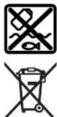
Copyright © 2011 Petteri Aimonen
This software is provided 'as-is', without any express or implied warranty. In no event will the authors be held liable for any damages arising from the use of this software.
Permission is granted to anyone to use this software for any purpose, including commercial applications, and to alter it and redistribute it freely, subject to the following restrictions:
- The origin of this software must not be misrepresented; you must not claim that you wrote the original software. If you use this software in a product, an acknowledgment in the product documentation would be appreciated but is not required.
- Altered source versions must be plainly marked as such, and must not be misrepresented as being the original software.
- This notice may not be removed or altered from any source distribution.
Apache 2.0 License
Copyright © 2009-2020 Arm Limited. All rights reserved.
Version 2.0, January 2004
http://www.apache.org/licenses/
TERMS AND CONDITIONS FOR USE, REPRODUCTION, AND DISTRIBUTION
1. Definitions.
"License" shall mean the terms and conditions for use, reproduction, and distribution as defined by Sections 1 through 9 of this document.
"Licensor" shall mean the copyright owner or entity authorized by the copyright owner that is granting the License.
"Legal Entity" shall mean the union of the acting entity and all other entities that control, are controlled by, or are under common control with that entity. For the purposes of this definition, "control" means (i) the power, direct or indirect, to cause the direction or management of such entity, whether by contract or otherwise, or (ii) ownership of fifty percent (50%) or more of the outstanding shares, or (iii) beneficial ownership of such entity.
"You" (or "Your") shall mean an individual or Legal Entity exercising permissions granted by this License.
"Source" form shall mean the preferred form for making modifications, including but not limited to software source code, documentation source, and configuration files.
"Object" form shall mean any form resulting from mechanical transformation or translation of a Source form, including but not limited to compiled object code, generated documentation, and conversions to other media types.
"Work" shall mean the work of authorship, whether in Source or Object form, made available under the License, as indicated by a copyright notice that is included in or attached to the work (an example is provided in the Appendix below).
"Derivative Works" shall mean any work, whether in Source or Object form, that is based on (or derived from) the Work and for which the editorial revisions, annotations, elaborations, or other modifications represent, as a whole, an original work of authorship. For the purposes of this License, Derivative Works shall not include works that remain separable from, or merely link (or bind by name) to the interfaces of, the Work and Derivative Works thereof.
"Contribution" shall mean any work of authorship, including the original version of the Work and any modifications or additions to that Work or Derivative Works thereof, that is intentionally submitted to Licensee for inclusion in the Work by the copyright owner or by an individual or Legal Entity authorized to submit on behalf of the copyright owner. For the purposes of this definition, "submitted" means any form of electronic, verbal, or written communication sent to the Licensee or its representatives, including but not limited to communication on electronic mailing lists, source code control systems,
and issue tracking systems that are managed by, or on behalf of, the Licensor for the purpose of discussing and improving the Work, but excluding communication that is conspicuously marked or otherwise designated in writing by the copyright owner as "Not a Contribution."
"Contributor" shall mean Licensee and any individual or Legal Entity on behalf of whom a Contribution has been received by Licensee and subsequently incorporated within the Work.
- Grant of Copyright License. Subject to the terms and conditions of this License, each Contributor hereby grants to You a perpetual, worldwide, non-exclusive, no-charge, royalty-free, irrevocable copyright license to reproduce, prepare Derivative Works of, publicly display, publicly perform, sublicense, and distribute the Work and such Derivative Works in Source or Object form.
- Grant of Patent License. Subject to the terms and conditions of this License, each Contributor hereby grants to You a perpetual, worldwide, non-exclusive, no-charge, royalty-free, irrevocable (except as stated in this section) patent license to make, have made, use, offer to sell, sell, import, and otherwise transfer the Work, where such license applies only to those patent claims licensable by such Contributor that are necessarily infringed by their Contribution(s) alone or by combination of their Contribution(s) with the Work to which such Contribution(s) was submitted. If You institute patent litigation against any entity (including a cross-claim or counterclaim in a lawsuit) alleging that the Work or a Contribution incorporated within the Work constitutes direct or contributory patent infringement, then any patent licenses granted to You under this License for that Work shall terminate as of the date such litigation is filed.
- Redistribution. You may reproduce and distribute copies of the Work or Derivative Works thereof in any medium, with or without modifications, and in Source or Object form, provided that You meet the following conditions:
- You must give any other recipients of the Work or Derivative Works a copy of this License; and
- You must cause any modified files to carry prominent notices stating that You changed the files; and
- You must retain, in the Source form of any Derivative Works that You distribute, all copyright, patent, trademark, and attribution notices from the Source form of the Work, excluding those notices that do not pertain to any part of the Derivative Works; and
- If the Work includes a "NOTICE" text file as part of its distribution, then any Derivative Works that You distribute must include a readable copy of the attribution notices contained within such NOTICE file, excluding those notices that do not pertain to any part of the Derivative Works, in at least one of the following places: within a NOTICE text file distributed as part of the Derivative Works; within the Source form or documentation, if provided along with the Derivative Works; or, within a display generated by the Derivative Works, if and wherever such third-party notices normally appear. The contents of the NOTICE file are for informational purposes only and do not modify the License.
You may add Your own attribution notices within Derivative Works that You distribute, alongside or as an addendum to the NOTICE text from the Work, provided that such additional attribution notices cannot be construed as modifying the License. You may add Your own copyright statement to Your modifications and may provide additional or different license terms and conditions for use, reproduction, or distribution of Your modifications, or for any such Derivative Works as a whole, provided Your use, reproduction, and distribution of the Work otherwise complies with the conditions stated in this License.
- Submission of Contributions. Unless You explicitly state otherwise, any Contribution intentionally submitted for inclusion in the Work by You to the Licensor shall be under the terms and conditions of this License, without any additional terms or conditions. Notwithstanding the above, nothing herein shall supersede or modify the terms of any
separate license agreement you may have executed with Licensor regarding such Contributions.
- Trademarks. This License does not grant permission to use the trade names, trademarks, service marks, or product names of the Licensor, except as required for reasonable and customary use in describing the origin of the Work and reproducing the content of the NOTICE file.
- Disclaimer of Warranty. Unless required by applicable law or agreed to in writing, Licensee provides the Work (and each Contributor provides its Contributions) on an "AS IS" BASIS, WITHOUT WARRANTY OR CONDITIONS OF ANY KIND, either express or implied, including, without limitation, any warranties or conditions of TITLE, NON-INFRINGEMENT, MERCHANTABILITY, or FITNESS FOR A PARTICULAR PURPOSE. You are solely responsible for determining the appropriateness of using or redistributing the Work and assume any risks associated with Your exercise of permissions under this License.
- Limitation of Liability. In no event and under no legal theory, whether in tort (including negligence), contract, or otherwise, unless required by applicable law (such as deliberate and grossly negligent acts) or agreed to in writing, shall any Contributor be liable to You for damages, including any direct, indirect, special, incidental, or consequential damages of any character arising as a result of this License or out of the use or inability to use the Work (including but not limited to damages for loss of goodwill, work stoppage, computer failure or malfunction, or any and all other commercial damages or losses), even if such Contributor has been advised of the possibility of such damages.
- Accepting Warranty or Additional Liability. While redistributing the Work or Derivative Works thereof, You may choose to offer, and charge a fee for, acceptance of support, warranty, indemnity, or other liability obligations and/or rights consistent with this License. However, in accepting such obligations, You may act only on Your own behalf and on Your sole responsibility, not on behalf of any other Contributor, and only if You agree to indemnify, defend, and hold each Contributor harmless for any liability incurred by, or claims asserted against, such Contributor by reason of your accepting any such warranty or additional liability.
END OF TERMS AND CONDITIONS
Copyright © 2010-2013 ARM LIMITED
All rights reserved.
Redistribution and use in source and binary forms, with or without modification, are permitted provided that the following conditions are met:
- Redistributions of source code must retain the above copyright notice, this list of conditions and the following disclaimer.
- Redistributions in binary form must reproduce the above copyright notice, this list of conditions and the following disclaimer in the documentation and/or other materials provided with the distribution.
- Neither the name of ARM nor the names of its contributors may be used to endorse or promote products derived from this software without specific prior written permission.
THIS SOFTWARE IS PROVIDED BY THE COPYRIGHT HOLDERS AND CONTRIBUTORS "AS IS" AND ANY EXPRESS OR IMPLIED WARRANTIES, INCLUDING, BUT NOT LIMITED TO, THE IMPLIED WARRANTIES OF MERCHANTABILITY AND FITNESS FOR A PARTICULAR PURPOSE ARE DISCLAIMED. IN NO EVENT SHALL THE COPYRIGHT HOLDERS AND CONTRIBUTORS BE LIABLE FOR ANY DIRECT, INDIRECT, INCIDENTAL, SPECIAL, EXEMPLARY, OR CONSEQUENTIAL DAMAGES (INCLUDING, BUT NOT LIMITED TO, PROCUREMENT OF SUBSTITUTE GOODS OR SERVICES; LOSS OF USE, DATA, OR PROFITS; OR BUSINESS INTERRUPTION) HOWEVER CAUSED AND ON ANY THEORY OF LIABILITY, WHETHER IN CONTRACT, STRICT LIABILITY, OR TORT (INCLUDING NEGLIGENCE OR OTHERWISE) ARISING IN ANY WAY OUT
OF THE USE OF THIS SOFTWARE, EVEN IF ADVISED OF THE POSSIBILITY OF SUCH DAMAGE.
Copyright © 2014 STMicroelectronics
Under STMicroelectronics' intellectual property rights, the redistribution, reproduction and use in source and binary forms of the software or any part thereof, with or without modification, are permitted provided that the following conditions are met:
- Redistribution of source code (modified or not) must retain any copyright notice, this list of conditions and the disclaimer set forth below as items 10 and 11.
- Redistributions in binary form, except as embedded into microcontroller or microprocessor device manufactured by or for STMicroelectronics or a software update for such device, must reproduce any copyright notice provided with the binary code, this list of conditions, and the disclaimer set forth below as items 10 and 11, in documentation and/or other materials provided with the distribution.
- Neither the name of STMicroelectronics nor the names of other contributors to this software may be used to endorse or promote products derived from this software or part thereof without specific written permission.
- This software or any part thereof, including modifications and/or derivative works of this software, must be used and execute solely and exclusively on or in combination with a microcontroller or microprocessor device manufactured by or for STMicroelectronics.
- No use, reproduction or redistribution of this software partially or totally may be done in any manner that would subject this software to any Open Source Terms. "Open Source Terms" shall mean any open source license which requires as part of distribution of software that the source code of such software is distributed therewith or otherwise made available, or open source license that substantially complies with the Open Source definition specified at www.opensource.org and any other comparable open source license such as for example GNU General Public License (GPL), Eclipse Public License (EPL), Apache Software License, BSD license or MIT license.
- STMicroelectronics has no obligation to provide any maintenance, support or updates for the software.
- The software is and will remain the exclusive property of STMicroelectronics and its licensors. The recipient will not take any action that jeopardizes STMicroelectronics' and its licensors' proprietary rights or acquire any rights in the software, except the limited rights specified hereunder.
- The recipient shall comply with all applicable laws and regulations affecting the use of the software or any part thereof, including any applicable export control law or regulation.
- Redistribution and use of this software or any part thereof other than as permitted under this license is void and will automatically terminate your rights under this license.
- THIS SOFTWARE IS PROVIDED BY STMICROELECTRONICS AND CONTRIBUTORS "AS IS" AND ANY EXPRESS, IMPLIED OR STATUTORY WARRANTIES, INCLUDING, BUT NOT LIMITED TO, THE IMPLIED WARRANTIES OF MERCHANTABILITY, FITNESS FOR A PARTICULAR PURPOSE AND NON-INFRINGEMENT OF THIRD PARTY INTELLECTUAL PROPERTY RIGHTS, WHICH ARE DISCLAIMED TO THE FULLEST EXTENT PERMITTED BY LAW. IN NO EVENT SHALL
STMICROELECTRONICS OR CONTRIBUTORS BE LIABLE FOR ANY DIRECT, INDIRECT, INCIDENTAL, SPECIAL, EXEMPLARY, OR CONSEQUENTIAL DAMAGES (INCLUDING, BUT NOT LIMITED TO, PROCUREMENT OF SUBSTITUTE GOODS OR SERVICES; LOSS OF USE, DATA, OR PROFITS; OR BUSINESS INTERRUPTION) HOWEVER CAUSED AND ON ANY THEORY OF LIABILITY, WHETHER IN CONTRACT, STRICT LIABILITY, OR TORT (INCLUDING NEGLIGENCE OR OTHERWISE) ARISING IN ANY WAY OUT OF THE USE OF THIS SOFTWARE, EVEN IF ADVISED OF THE POSSIBILITY OF SUCH DAMAGE.
- EXCEPT AS EXPRESSLY PERMITTED HEREUNDER, NO LICENSE OR OTHER RIGHTS, WHETHER EXPRESS OR IMPLIED, ARE GRANTED UNDER ANY PATENT OR OTHER INTELLECTUAL PROPERTY RIGHTS OF STMICROELECTRONICS OR ANY THIRD PARTY.
| de | EU-Konformitäserkläragung | Wir erklären in alleiniger Verantwortung, dass die genannten Produkte allen einschlagigen Bestimmungen der nachfolgenden aufgeführten Richtlinien und Verordnungen entsprechen und mit folgenden Normen übereinstimmen. Technische Unterlagen bei: * | |
| Akku-Paneelsäge | Sachnummer | ||
| en | EU Declaration of Conformity | We declare under our sole responsibility that the stated products comply with all applicable provisions of the directives and regulations listed below and are in conformity with the following standards. Technical file at: * | |
| Cordless sliding mitre saw | Article number | ||
| fr | Déclaration de conformité UE | Nous déclarons sous notre propre responsabilité que les produits décrits sont en conformité avec les directives, règlements normatifs et normes écummérés ci-dessous. Dossier technique auprès de : * | |
| Scie à onglets radiale sans-fil | N° d'article | ||
| es | Déclaration de conformidad UE | Declaramos bajo notre extraure responsabilité, que les produits nombrados complen con todas las disposiciones correspondientes de las Directivas y los Regimientos Mentionados a continuación y está en conformidad con las siguientes normas. Documentos tíncicos de: * | |
| Ingletable telescópica'actionada poraccumulador | N° de articulo | ||
| pt | Déclaration de Conformidade UE | Declaramos sob esta exclusiva responsabilité que os produits mencionados cumprem todas as dispositions e os regulamentos indicados est叠加 em conformidade com as seguições normas. Documentação técnica pertencente à: * | |
| Serra para painéis sem fio | N.° do produit | ||
| it | Dichiarazione di conformità UE | Dichiariamo sulla sua piena responsabilità che i prodotti indicate sono conformi a tutte le dispositions pertinenti delle Direttive e dei Regolamenti elencati di seguito, nonché alle seguenti Normative. Documentazione Tecnica presso: * | |
| Troncatrice radiale a batteria | Codice prodotto | ||
| nl | EU-conformiteitsverklaring | Wij verklaren op eigenverantwoordelijkheid dat de genoemde producten voldoen aan alle desbeteffende bepalingen van de hierna genoemde richtlijnen en verorderingen en overeenstemmen met de volgende normen. Technisch dossier bij: * | |
| Accurdiaalzaag | Productnummer | ||
| da | EU-overensstemmelseserklaering | Vi erklarer someneansvarlige, at det beskreve Produkt er i overensstemmelse med alle gändende bestemmelse i falgende direktiver og forordninger og opfylder falgende standarder. Tekniske bilag ved: * | |
| Akku-kap- oggeringsssav | Typenummer | ||
| sv | EU-konformitetsförklaring | Vi föklarar under eget ansvar att de námnda produktura uppyller kraven i alla gällande bestämelse med el nedan angivna direktiven och Förordningarnas och att de stämmer överens med följande normer. Teknisk documentation: * | |
| Sladdlós panelsåg | Produktnummer | ||
| no | EU-samsvarserklaering | Vi erklærer undereneansvar at de nevnte Produktene er i overensstemmelse med alle relevante bestemmelse i direktivene og forordningene nedenfor og med falgende standarder. Teknisk documentationsjön hos: * | |
| Batteridrevet kapp-oggjaeringsssag | Produktnummer | ||
| fi | EU-vaatimustemmukaisuusvakuutus | Vakuutamme täten, etta mainitut tuotteet vastaavat kaikkia seuraavien direktivien ja asetusten asiaankuulvia vaatimuksaia ja ovat seuraavien standardien vaatimusten mukaisia. Teknisenet asiakirjat saatavana: * | |
| Akkukäytöinen katkaisu- jajiirisaha | Tuotenumero | ||
| el | Δηλωση πιστότητας EE | Δηλώνομε με απολείοικη μας ευθύνη, ὄπι τα συφερόμενα προίουντα Αντιατούνουν σελείς Μχότεκε διατάξεις των πιο κατων αυφερόμενων σθηγων και κανονισμων και ταυτιζόνται με to ακόλουθα πρότιμα. Tεχυκα ἀγραρα στη: * | |
| Φαλτοπρίονo Radial μματρίας | Αρβεύς ευρετηρίου | ||
| tr | AB Uygunluk beyani | Tek sorumlou olarak, tanımlanan ürünün asaqidaki)yönnetmelik ve direktiflerin geleçeri buttūhūkümlerine ve asaqidaki standartlara uygun olduguṇu beyan ederiz. Teknik belgelerin bulundugu yer: * | |
| Akūli gōnye kesme makinesi | Uṛn kodu | ||
| II | ||
| pl | Deklaracja zgodnosci UE | Oswiadczamy z pełną odpopiewiazniść, ze nineje}sze produkty odpowiadaj wszystkim wymaganium poniżej wyszczejnlionych dyrektyw i Rozporzadźne, oraz ze są zgodne z następućymi normami. Dokumentacja techniczna:* |
| Akumulatorowa ukośnica do paneli Numer katalogowy | Prohlasujeme na vyhradní zodpovednost, ze uvedeny výrobek spólnej vsechna príslušné ustanoveni ninee uvedenych směrnic anaženíaje vsouladu snáskedujicimi normami: Teknicke podklady u:* | |
| cs | EU prohlášeni oshodé | Vyhlasujeme na vyhradní zodpovednost, ze uvedeny výrobek spólna vsetky príslušné ustanoveni ninee uvedenych směrnica anaadieníaje vsúlade snáskedujicimi normami: Teknicke podklady má spolocnost:* |
| Akumulatorová objednaci cislo | Egyedūli feleşseggel kijelentjuk, hogy a megnevezett termék megfelelnek az alabbiakban felsorolára kerulō irányvelk és rendeleket valamennyi idevágó elöirásainak és megfelelnek k ákovtekö szabványoknak. Mûszaki dokumentumok megörzési pontja:* | |
| sk | EU vyhlásenie ozhode | Vyhlasujeme na vyhradní zodpovednost, ze uvedeny výrobek spólna vsetky príslušné ustanoveni ninee uvedenych směrnica anaadieníaje vsúlade snáskedujicimi normami: Teknicke podklady má spolocnost:* |
| Akumulatorová Vecné cislo | Egyedūli feleşseggel kijelentjuk, hogy a megnevezett termék megfelelnek az alabbiakban felsorolára kerulō irányvelk és rendeleket valamennyi idevágó elöirásainak és megfelelnek k ákovtekö szabványoknak. Mûszaki dokumentumokMegörzési pontja:* | |
| hu | EU konformitási nyilatkozat | Mbl 3aBbIbEm Pod náhu yednoho nuHyU OTBETCTBEHOCbT,чTo náBaHbIbe IpoJyKbIbCoTBTCTBYOT BCEM DeIcTBYIOUIM PpeJINsCAnHIM HnKeykaZaHbIX DnPeKTbN I pAcNoPjaKHeN, a TAKKe HnKeykaZaHaHbIX HOpM. TexNHuecka JOKyMeHTaJIa XpaHITcY y:* |
| Akkus sines Cikkszám | Mlb 3aBbIbEm Pod náhu yednoho nuHyU OTBETCTBEHOCbT,чTo náBaHbIbe IpoJyKbIbCoTBTCTBYOT BCEM DeIcTBYIOUIM PpeJINsCAnHIM HnKeykaZaHaHbIX DnPeKTbN I pAcNoPjaKHeN, a TAKKe HnKeykaZaHaHbIX HOpM. | |
| ru | 3aBbIbIbEm o COOTBETCTBNI EC | Mlb 3aBbIbEm Pod náhu yednoho nuHyU OTBETCTBEHOCbT,чTo náBaHbIbe IpoJyKbIbCoTBTCTBYOT BCEM DeIcTBYIOUIM PpeJINsCAnHIM HnKeykaZaHaHbIX DnPeKTbN I pAcNoPjaKBeHbN, a TAKKe HnKeykaZaHaHbIX HOpM. |
| Akkymylantopnay ToBapný No | Mlb 3aBbIbEm Pod náhu yednoho nuHyU OTBETCTBEHOCbT,чTo náBaHbIbe IpoJyKbIbCoTBTCTBYOT BCEM DeIcTBYIOUIM PpeJINsCAnHIM HnKeykaZaHaHbIX DnPeKTbN I pAcNoPjaKbHbN, a TAKKe HnKeykaZaHaHbIX HOpM. | |
| PahenbHa Nnla | IpoJyKbIbCoTBTbN I pAcNoPjaKBeHbN, a TAKKe HnKeykaZaHaHbIX DnPeKTbN I pAcNoPjaKbHbN, a TAKKe HnKeykaZaHaHbIX DnPeKTbN I pAcNoPjaKbHbN, a TAKKe HnKeykaZaHaHbIX DnPeKTbN I pAcNoPjaKbHbN, a TAKKe HnKeykaZaHaHbIX DnPeKTbN I pAcNoPjaKbHaHbN, a TAKKe HnKeykaZaHaHbIX DnPeKTbN I pAcNoPjaKbHaHbN, a TAKKe HnKeykaZaHaHbIX DnPeKTbN I pAcNoPjaKbHaHbN, a TAKKe HnKeykaZaHaHbIX DnPeKTbN I pAcNoPjaHaHaHbN, a TAKKe HnKeykaZaHaHbIX DnPeKTbN I pAcNoPjaHaHaHbN, a TAKKe HnKeykaZaHaHbIX DnPeKTbN I pAcNoPjaHaHaHbN, a TAKKe HnKeykaZaHaHbIX DnPeKTbN I pAcNoPjaHaHbN, a TAKKe HnKeykaZaHaHbIX DnPeKTbN I pAcNoPjaHaHaHbN, a TAKKe HnKeykaZaHaHbIX DnPeKTbN I pAcNoPjaHaHaHbN, a TAKKe HnKeykaZaHaHbIX DnPeKTbN I pAcNoPjaHa HaHaHbN, a TAKKe HnKeykaZaHaHaHbIX DnPeKTbN I pAcNoPjaHaHaHaHaHbN, a TAKKe HnKeykaZaHaHaHaHaHaHbN, a TAKKe HnKeykaZaHaHaHaHaHaHaHaHaHaHaHaHaHaHaHaHaHaHaHaHaHaHaHaHaHaHaHaHaHaHaHaHaHaHaHaHaHaHaHaHaHaHaHaHaHaHaHaHaHaHaHaHaHaHaHaHaHaHaHaHaHaHaHaHaHaHaHaHaHaHaHaHaHaHaHaHaHaHaHaHaHaHaHaHaHaHaHaHaHaHaHaHaHaHaHaHaHaHaHaHa HaHaHaHaHaHaHaHaHaHaHaHaHaHaHaHaHaHaHaHaHaHaHaHaHaHaHaHaHaHaHaHaHaHaHaHaHaHaHaHaHaHaHaHaHaHaHaHaHaHaHaHaHaHaHaHaHaHaHaHaHaHaHaHaHaHaHaHaHaHaHaHaHaHaHaHaHaHaHaHaHaHaHaHaHaHaHaHaHaHaHaHaHaHaHaHaHaHaHaHaHAHaHaHaHaHaHaHaHaHaHaHaHaHaHaHaHaHaHaHaHaHaHaHaHaHaHaHaHaHaHaHaHaHaHaHaHaHaHaHaHaHaHaHaHaHaHaHaHaHaHaHaHaHaHaHaHaHaHaHaHaHaHaHaHaHaHaHaHaHaHaHaHaHaHaHaHaHaHaHaHaHaHaHaHaHaHaHaHaHaHaHaHaHaHaHaHaHaHaHaHo | |
| Akkymylantopnay ToBapný Homep | BnPoJ NaDen/APTKnI | |
| Akkymylantopnay ToBapný Homep | BnPoJ NaDen/APTKnI | |
| PahenbHa Nnla | IpoJyKbIbCoTBTbN I pAcNoPjaKBeHbN, a TAKKe HnKeykaZaHaHbIX DnPeTBTCTBA NcIeNDHTe CTaNDArtN. | |
| rk | EO cāIkectik MaFmДamacby | Ozelayankepuiiknēn 63 aTaIafan Čemdēn TemeHne Jx3bIyFaH |
| Akkymylantopnay Šním Hmapi | DnPeKTbN KApNáIaR MEn Jx3bIyFaH | |
| PahenbHa Nnla | IpoJyKbIbCoTBTbN I pAcNoPjaKBeHbN, a TAKKe HnKeykaZaHaHbIX DnPeTBTCTBA NcIeNDHTe CTaNDArtN. | |
| ro | Declaratié de conformitate UE | Declaram pe proprié raspundere cā produsele mentionate corespendut tuturor disposjiilor relevante ale directivel.si reglementärlor enumerate in celece urmează.si sunt in conformitate cu umratoarele standarde. Documentatie tehnica la:* |
| Ferăstră circular Numar de identificare staionar cu sanie de glisare si acumulator | Cпьлна otroворон'tипс ду�шпесу рiodуктп otroворян на BCNUKN BANUДN ИЗСКВВИЕ на Ду�спьпс и радоцдппп.Tо-Доулс и СытВETCTBA NcIeNDHTe CTaNDArtN. | |
| bg | EC děknapaúna 3a StbOTBETCTBNe | Cпьлна otroворон'tипс ду�шпесу рiodуктп otroворян на BCNUKN BANUДN ИЗСКВВИЕ на Ду�спьпс и радоцдппп.Tо-Доулс и СытВETCTBA NcIeNDHTe CTaNDArtN. |
| CE | |||
| da su sukladni sa sljedećim normama. Tehnička dokumentaci je说我 dobiti kod: * | |||
| et | EL-vastavusdeklaratsion | Kinnitame ainuvastutajatena, et nimetatud tooted vastavad järgnevalt loetletud direktivide ja määruste kõikidele asjaomastele nõuetele ja on kooskõlas järgmiste normidega. Tehnilised dokumendid saadaval: * | |
| Aku-paneelsaag Tootenumber | |||
| lv | Deklarácija par atbilstibu ES standartiem | Mës ar pilnu atbildibu pazinojam, ka šeit aplūkotie izstrādājumi atbilst visiem tålak minētajās direktivās un rikojumos ietvertajām saistosajām nostādnēm, kã āri sekojošiem standartiem. Tehniskā Dokumentăcija no: * | |
| Akumulatora Izstrādājuma numurs panelzägl | |||
| lt | ES atitikties deklaracija | Atsakingai pareiskiame, kad išvardyti gaminiai atitinka visus privalomus žemiau nurodytu direktvyu ir reglamentu reikalavimus ir šiuos standartus. Techniné dokumentacijs saugoma: * | |
| Akumulatorinis Gaminio numeris slankusis skersavimo ir suleidimo pjūklas | |||
| 2006/42/EC EN 62841-1:2015+A11:2022 2014/30/EU EN IEC 62841-3-9:2020+A11:2020 2011/65/EU EN IEC 55014-1:2021 EN IEC 55014-2:2021 EN IEC 63000:2018 | |||
| BOSCH * Robert Bosch Power Tools GmbH (PT/ECS) 70538 Stuttgart GERMANY | |||
| Henk Becker Helmut Heinzelmann Chairman of Head of Product Certification Executive Management | |||
| Robert Bosch Power Tools GmbH, 70538 Stuttgart, GERMANY Stuttgart, 18.11.2022 | |||
Declaration of Conformity
Cordless sliding litre saw Article number
GCM 18V-254D3601M51100
We declare under our sole responsibility that the stated products comply with all applicable provisions of the regulations listed below and are in conformity with the following standards.
Technical file at: Robert Bosch Ltd. (PT/SOP-GB), Broadwater Park, North Orbital Road, Uxbridge UB9 5HJ, United Kingdom
The Supply of Machinery (Safety) Regulations 2008
The Electromagnetic Compatibility Regulations 2016
The Restriction of the Use of Certain Hazardous Substances in
Electrical and Electronic Equipment Regulations 2012
EN62841-1:2015+A11:2022
ENIEC62841-3-9:2020+A11:2020
ENIEC55014-1:2021
EN IEC 55014-2:2021
ENIEC63000:2018

BOSCH
Vonji Rajakoba
Managing Director - Bosch UK
Robert Bosch Power Tools GmbH, 70538 Stuttgart, Germany represented (in terms of the above regulations) by
Robert Bosch Limited, Broadwater Park, North Orbital Road, Uxbridge UB9 5HJ, United Kingdom
Martin Sibley
Head of Sales Operations and Aftersales
Robert Bosch Ltd. Broadwater Park, North Orbital Road, Uxbridge UB9 5HJ, United Kingdom, as authorised representative acting on behalf of Robert Bosch Power Tools GmbH, 70538 Stuttgart, Germany
Place of issue: Uxbridge Date of issue: 18/11/2022


- TRANSPORT
- GENERAL POWER TOOL SAFETY WARNINGS
- WARNING
- WORK AREA SAFETY
- ELECTRICAL SAFETY
- PERSONAL SAFETY
- POWER TOOL USE AND CARE
- BATTERY TOOL USE AND CARE
- SERVICE
- SAFETY WARNINGS FOR MITRE SAWS
- SYMBOLS
- SYMBOLS AND THEIR MEANING
- PRODUCT DESCRIPTION AND SPECIFICATIONS
- INTENDED USE
- PRODUCT FEATURES
- ENGLISH
- TECHNICAL DATA
- CORDLESS SLIDING LITRE SAW GCM 18V-254 D GCM 18V-254 D
- DIMENSIONS OF SUITABLE SAW BLADES
- NOISE INFORMATION
- WEAR HEARING PROTECTION
- RECHARGEABLE BATTERY
- CHARGING THE BATTERY
- INSERTING THE BATTERY
- REMOVING THE BATTERY
- BATTERY CHARGE INDICATOR
- LED CAPACITY
- RECOMMENDATIONS FOR OPTIMAL HANDLING OF THE BATTERY
- ASSEMBLY
- ITEMS INCLUDED
- FITTING INDIVIDUAL COMPONENTS
- INSTALLING WORKPIECE SUPPORTS (SEE FIGURE A1)
- FITTING THE CLAMPING WHEEL (SEE FIGURE A2)
- FITTING THE ADJUSTABLE FENCE (SEE FIGURE A3)
- STATIONARY OR FLEXIBLE MOUNTING
- MOUNTING ON A WORK SURFACE (SEE FIGURES B1-B2)
- MOUNTING ON A BOSCH SAW STAND
- FLEXIBLE INSTALLATION (NOT RECOMMENDED) (SEE FIGURE B3)
- DUST/CHIP EXTRACTION
- SELF-GENERATED DUST EXTRACTION (SEE FIGURE C)
- EXTERNAL DUST EXTRACTION
- CHANGING THE SAW BLADE (SEE FIGURES D1-D4)
- REMOVING THE SAW BLADE
- FITTING THE SAW BLADE
- OPERATION
- TRANSPORT SAFETY LOCK (SEE FIGURE E)
- UNLOCKING THE POWER TOOL (WORK POSITION)
- LOCKING THE POWER TOOL (TRANSPORT POSITION)
- PREPARING FOR OPERATION
- EXTENDING/EXPANDING THE SAW TABLE (SEE FIGURES F-G)
- MOVING THE FENCE (SEE FIGURE H)
- CLAMPING THE WORKPIECE (SEE FIGURE 1)
- ADJUSTING MITRE ANGLES
- SETTING STANDARD MITRE ANGLES (SEE FIGURE J)
- LEFT RIGHT
- °
- SETTING ANY MITRE ANGLE (SEE FIGURE K)
- ADJUSTING BEVEL ANGLES
- SETTING STANDARD BEVEL ANGLES (SEE FIGURE L)
- SETTING ANY BEVEL ANGLE
- START-UP
- SWITCHING ON (SEE FIGURE M)
- SWITCHING OFF
- SAWING
- GENERAL SAWING INSTRUCTIONS
- POSITION OF THE OPERATOR (SEE FIGURE N)
- SAWING WITH SLIDE MOVEMENT
- SAWING WITHOUT SLIDE MOVEMENT (CUTTING OFF) (SEE FIGURE O)
- PRACTICAL ADVICE
- MARKING THE CUTTING LINE (SEE FIGURE P)
- PERMISSIBLE WORKPIECE DIMENSIONS
- MITRE ANGLE BEVEL ANGLE HEIGHT X WIDTH
- MITRE ANGLE BEVEL ANGLE HEIGHT X WIDTH [MM]
- ADJUSTING THE DEPTH STOP (SAWING THE GROOVE) (SEE FIGURE Q)
- SAWING WORKPIECES OF THE SAME LENGTH (SEE FIGURE R)
- SPECIAL WORKPIECES
- REPLACING INSERT PLATES (SEE FIGURE S)
- ADJUSTING THE LASER
- CHECKING (SEE FIGURE T1)
- REMOVING THE LASER PROTECTION CAP (SEE FIGURE T2)
- ADJUSTING THE LATERAL DEVIATION WHEN MOVING THE TOOL ARM (SEE FIGURES T3-T4)
- CHECKING AND ADJUSTING THE BASIC SETTINGS
- ALIGNING THE LITRE ANGLE INDICATOR (SEE FIGURE U)
- CHECKING
- SETTING
- ALIGNING THE ANGLE INDICATOR (VERTICAL) (SEE FIGURE V)
- TRANSPORTING THE POWER TOOL (SEE FIGURE W)
- MAINTENANCE AND SERVICE
- MAINTENANCE AND CLEANING
- NOISE REDUCTION MEASURES
- AFTER-SALES SERVICE AND APPLICATION SERVICE
- GREAT BRITAIN
- YOU CAN FIND FURTHER SERVICE ADDRESSES AT
- DISPOSAL
- ONLY FOR EU COUNTRIES
- ONLY FOR UNITED KINGDOM
- BATTERY PACKS/BATTERIES
- YOU CAN FIND MORE CONTACT INFORMATION FOR SERVICE HERE
- MOUNTING ON A BOSCH WORKBENCH
- MOUNTING POSITION (6 COMPONENTS) (SEE FIGURE B3)
- DUST EXTRACTION/CHIP EXTRACTION
- PROTECTIVE CAP OF THE CHARGING UNIT (SEE FIGURE T2)
- POLSKI
- NAKLIYE
- TRANSPORTATION
- SAFETY INSTRUCTIONS
- GENERAL SAFETY INSTRUCTIONS FOR POWER TOOLS
- THE TERM "POWER TOOL" USED IN THESE INSTRUCTIONS AND WARNINGS REFERS TO POWER TOOLS OPERATED FROM THE MAINS (WITH A POWER CORD) AND BATTERY-OPERATED POWER TOOLS (WITHOUT A POWER CORD)
- KEEP YOUR WORKPLACE CLEAN AND WELL LIT. CLUTTERED OR DARK AREAS CAN LEAD TO ACCIDENTS. DO NOT OPERATE POWER TOOLS IN EXPLOSIVE ATMOSPHERES, E.G., IN THE PRESENCE OF FLAMMABLE LIQUIDS, FLAMMABLE GASES OR DUST. POWER TOOLS CREATE SPARKS, WHICH MAY IGNITE DUST OR FUMES. WHILE WORKING WITH A POWER TOOL, DO NOT ALLOW BYSTANDERS NEAR YOUR WORKPLACE. DISTRACTION CAN CAUSE YOU TO LOSE CONTROL OF THE POWER TOOL. THE EQUIPMENT IS INTENDED FOR USE IN HOUSEHOLD CONDITIONS, COMMERCIAL AREAS AND PUBLIC PLACES, INDUSTRIAL AREAS WITH LOW POWER CONSUMPTION, WITHOUT EXPOSURE TO HARMFUL AND HAZARDOUS PRODUCTION FACTORS. THE EQUIPMENT IS INTENDED FOR OPERATION WITHOUT CONSTANT PRESENCE OF SERVICE PERSONNEL
- SAFETY
- USE OF THE POWER TOOL AND HANDLING IT
- USE AND CARE OF BATTERY-POWERED TOOLS
- SAFETY INSTRUCTIONS FOR RECIPROCATING SAWS
- M511B. 3601M
- PRODUCT AND SERVICE DESCRIPTION
- ILLUSTRATED COMPONENTS
- RUSSIAN
- NOISE DATA
- USE HEARING PROTECTION
- BATTERY
- INSTALLING THE BATTERY
- INSTRUCTIONS FOR OPTIMAL HANDLING OF THE BATTERY
- SCOPE OF DELIVERY
- ASSEMBLY OF INDIVIDUAL PARTS
- INSTALLING THE WORKPIECE SUPPORTS (SEE FIG. A1)
- INSTALLING THE LOCKING KNOB (SEE FIG. A2)
- INSTALLING THE ADJUSTABLE PARALLEL GUIDE (SEE FIG. A3)
- STATIONARY OR TEMPORARY STAND
- MOUNTING ON A WORK SURFACE (SEE FIG. B1-B2)
- MOUNTING ON A BOSCH PRODUCTION TABLE
- ANTI-TIP DEVICE (RECOMMENDED!) (SEE FIG. B3)
- DUST AND CHIP REMOVAL
- INTEGRATED DUST EXTRACTION SYSTEM (SEE FIG. C)
- REPLACING THE SAW BLADE (SEE FIGURES D1-D4)
- MOUNTING THE SAW BLADE
- WORKING WITH THE TOOL
- TRANSPORT GUARD (SEE FIG. E)
- REMOVING THE TRANSPORT GUARD (WORKING POSITION)
- ACTIVATING THE TRANSPORT GUARD (TRANSPORT POSITION)
- PREPARATION FOR OPERATION
- EXTENDING/EXPANDING THE SAW TABLE (SEE FIG. F-G)
- ADJUSTING THE STOP PLATE (SEE FIG. H)
- SETTING THE HORIZONTAL MITER ANGLE
- SETTING THE STANDARD HORIZONTAL MITER ANGLE (SEE FIG. J)
- SETTING AN ARBITRARY HORIZONTAL MITER ANGLE (SEE FIG. K)
- SETTING THE STOP FOR CUTTING A GROOVE (SEE FIG. Q)
- CUTTING WORKPIECES OF THE SAME LENGTH (SEE FIG. R)
- REPLACING THE INSERT PLATE (SEE FIG. 8)
- CONTROL (SEE FIG. T1)
- REMOVING THE LASER PROTECTIVE CAP (SEE FIG. T2)
- ADJUSTING THE LATERAL DEVIATION WHEN MOVING THE TOOL HEAD (SEE FIG. T3-T4)
- BASIC SETTINGS - CHECK AND CORRECTION
- CHECKING THE HORIZONTAL LASER BEAM ANGLE INDICATOR (SEE FIGURE U)
- CHECK
- ADJUSTMENT
- CENTERING THE VERTICAL LASER BEAM ANGLE INDICATOR (SEE FIGURE V)
- HACTPOKA
- ТРАНСПОРТИРОВКА ЭЛЕКТРОИНСТРУМЕНТА (СМ. РИС. W)
- ТЕХОБСЛУЖИВАНИЕ И СЕРВИС
- ТЕХОБСЛУЖИВАНИЕ И ОЧИСТКА
- MEASURES TO REDUCE NOISE LEVEL
- SERVICE AND CONSULTATION ON APPLICATION ISSUES
- WWW.BOSCH-PT.COM
- ONLY FOR EU MEMBER STATES
- BATTERIES
- LITHIUM-ION
- UKRAINIAN
- TYPE THE FUTURE TENSE AND INDICATE THE WARNING SIGNS
- SYMBOLS AND THEIR MEANINGS
- M
- DIMENSIONS OF THE WORKING TOOL
- BATTERY CHARGING
- DISCHARGE MINUTES
- INDICATION OF OPTIMAL CHARGING WITH BATTERY
- INSTALLING THE WORKPIECE SUPPORT (SEE FIG. A1)
- INSTALLING THE CLAMPING WHEEL (SEE FIG. A2)
- INSTALLING THE ADJUSTABLE STOP RAIL (SEE FIG. A3)
- BOSCH POWER TOOL BENCH
- IMPROPER MOUNTING (NOT RECOMMENDED!) (SEE FIG. B3)
- BUILT-IN DUST EXTRACTION (SEE FIG. C)
- EXTERNAL SUCTION
- TRANSPORT FIXING (SEE FIGURE E)
- RELEASE THE FIXING (WORKING POSITION)
- FIXING THE POWER TOOL (TRANSPORT POSITION)
- PREPARATION FOR WORK
- RAISING/LOWERING THE TABLE (SEE FIGURE F-G)
- ADJUSTING THE TILT ANGLE (SEE FIGURE H)
- ADJUSTING STANDARD VERTICAL TILT ANGLES (SEE FIGURE I)
- ADJUSTING THE VERTICAL TILT ANGLES
- SWITCHING ON (SEE FIGURE J)
- SWITCHING ON
- GENERAL INSTRUCTIONS FOR ADJUSTMENT
- SHARPENING
- CHECKING (SEE FIG. T1)
- REPLACING THE LASER BATTERY (SEE FIG. T2)
- ADJUSTING THE LASER BEAM WHEN MOVING THE BRACKET OF THE POWER TOOL (SEE FIG. T3-T4)
- CHECKING AND ADJUSTING THE BASIC PARAMETERS
- ADJUSTING THE ANGLE INDICATOR (HORIZONTAL) (SEE FIG. 1)
- ADJUSTING THE ANGLE INDICATOR (VERTICAL) (SEE FIG. 2)
- LAWS REGARDING DUST EXTRACTION
- SERVICE AND CONSULTATION ON USAGE QUESTIONS
- UKRAINE
- ADDRESSES OF OTHER SERVICE CENTERS ARE LISTED BELOW
- KAZAKH
- EURASIAN ECONOMIC UNION (EEU) CONFORMITY
- MEASUREMENT PROCEDURE
- PRECAUTIONS AND WARNINGS
- CLEANING AND MAINTENANCE
- SERVICE LIFE AND STORAGE
- STORAGE
- FOR ELECTRIC HEATERS, SAFETY INSTRUCTIONS
- EXPERTS
- INSTRUCTIONS, FIGURES, AND SPECIFICATIONS
- FOR YOUR SAFETY, FOLLOW THE SAFETY INSTRUCTIONS AND WARNINGS
- SAFETY OF THE HEATER
- ELECTRIC SAFETY
- ELECTRIC CURRENT CAN CAUSE INJURY
- BATTERY SWITCH INSTALLATION AND MAINTENANCE
- SERVICE INSTRUCTIONS
- SAFETY INSTRUCTIONS FOR THE USER
- SPECIFICATIONS
- SPECIFICATIONS AND DESCRIPTION
- ELECTRICAL AND GAS CONNECTION DIAGRAM
- SETTING THE PRESSURE SWITCH
- REPLACEMENT OF THE FILTER ELEMENT
- INSTALLATION OF THE BOSCH KOUMISS UNIT
- INSTALLATION INSTRUCTIONS (FOR THE USER!) (SEE FIGURE)
- WATER FILTER (SEE FIGURE C)
- EXTERNAL FILTER
- REPLACE THE CUTTING BLADE (D1-D4 CUTTING DISCS)
- REPLACING THE CUTTING DISC
- INSTALLING THE CUTTING DISC
- DURING OPERATION, HOLD THE TOOL FIRMLY (SEE FIGURE E)
- ELECTRIC POWER TOOL INTENDED FOR CUTTING (DRY CUTTING)
- DRY CUTTING
- KEDERE KAPATY
- TEK KAHA EO ENEEPI YUH
- AKKYMYTOPNAP/6ATAPEENNAP
- JIHTHNIHOHNBIK
- ROMÂNA
- INSTRUŢIUNI DE SIGURANTA
- GENERAL SAFETY INSTRUCTIONS FOR SAFE WORK
- THE TERM "POWER TOOL" IN THE WARNINGS REFERS TO YOUR MAINS-OPERATED (CORDED) POWER TOOL OR BATTERY-OPERATED (CORDLESS) POWER TOOL
- KEEP WORK AREA CLEAN AND WELL LIT. CLUTTERED OR DARK AREAS INVITE ACCIDENTS. DO NOT OPERATE POWER TOOLS IN EXPLOSIVE ATMOSPHERES, SUCH AS IN THE PRESENCE OF FLAMMABLE LIQUIDS, GASES OR DUST. POWER TOOLS CREATE SPARKS WHICH MAY IGNITE THE DUST OR FUMES. KEEP CHILDREN AND BYSTANDERS AWAY WHILE OPERATING A POWER TOOL. DISTRACTIONS CAN CAUSE YOU TO LOSE CONTROL
- POWER TOOL PLUGS MUST MATCH THE OUTLET. NEVER MODIFY THE PLUG IN ANY WAY. DO NOT USE ANY ADAPTER PLUGS WITH EARTHED (GROUNDED) POWER TOOLS. UNMODIFIED PLUGS AND MATCHING OUTLETS WILL REDUCE RISK OF ELECTRIC SHOCK. AVOID BODY CONTACT WITH EARTHED OR GROUNDED SURFACES, SUCH AS PIPES, RADIATORS, RANGES AND REFRIGERATORS. THERE IS AN INCREASED RISK OF ELECTRIC SHOCK IF YOUR BODY IS EARTHED OR GROUNDED. DO NOT EXPOSE POWER TOOLS TO RAIN OR WET CONDITIONS. WATER ENTERING A POWER TOOL WILL INCREASE THE RISK OF ELECTRIC SHOCK. DO NOT ABUSE THE CORD. NEVER USE THE CORD FOR CARRYING, PULLING OR UNPLUGGING THE POWER TOOL. KEEP CORD AWAY FROM HEAT, OIL, SHARP EDGES OR MOVING PARTS. DAMAGED OR ENTANGLED CORDS INCREASE THE RISK OF ELECTRIC SHOCK. WHEN OPERATING A POWER TOOL OUTDOORS, USE AN EXTENSION CORD SUITABLE FOR OUTDOOR USE. USE OF A CORD SUITABLE FOR OUTDOOR USE REDUCES THE RISK OF ELECTRIC SHOCK. IF OPERATING A POWER TOOL IN A DAMP LOCATION IS UNAVOIDABLE, USE A RESIDUAL CURRENT DEVICE (RCD) PROTECTED SUPPLY. USE OF AN RCD REDUCES THE RISK OF ELECTRIC SHOCK
- STAY ALERT, WATCH WHAT YOU ARE DOING AND USE COMMON SENSE WHEN OPERATING A POWER TOOL. DO NOT USE A POWER TOOL WHILE YOU ARE TIRED OR UNDER THE INFLUENCE OF DRUGS, ALCOHOL OR MEDICATION. A MOMENT OF INATTENTION WHILE OPERATING POWER TOOLS MAY RESULT IN SERIOUS PERSONAL INJURY
- SAFETY WARNINGS FOR POWER TOOLS
- SAFETY WARNINGS FOR BATTERY-OPERATED POWER TOOLS
- MAINTENANCE
- SAFETY WARNINGS FOR CIRCULAR SAWS
- PRODUCT DESCRIPTION AND PERFORMANCE
- INTENDED USE OF THE POWER TOOL
- BULGARIAN
- INFORMATION ABOUT NOISE
- WEAR EAR PROTECTION
- BATTERY PACK
- CHARGING THE BATTERY PACK
- INSERTING THE BATTERY PACK
- REMOVING THE BATTERY PACK
- CHARGE LEVEL INDICATOR
- BATTERY PACK PROCORE18V
- INSTRUCTIONS FOR OPTIMAL OPERATION OF THE BATTERY
- MOUNTING
- PACKAGE CONTENTS
- INSTALLING ACCESSORIES
- INSTALLING THE SUPPORT FOR WORKPIECES (SEE FIG. A1)
- STATIONARY AND MOBILE INSTALLATION
- MOUNTING ON A WALL (SEE FIG. B3)
- DUST EXTRACTION SYSTEM
- SELF-GENERATED DUST EXTRACTION (SEE FIG. C)
- CHANGING AND ADJUSTING THE SANDING DISC (SEE FIG. D1–D4)
- REMOVING THE CIRCULAR SAW BLADE
- MOUNTING THE CIRCULAR SAW BLADE
- WORKING WITH THE POWER TOOL
- TRANSPORT SAFETY (SEE FIGURE E)
- RELEASING THE POWER TOOL (WORKING POSITION)
- POWER TOOL COVER (TRANSPORT POSITION)
- REMOVING THE DUST EXTRACTION ADAPTER (SEE FIGURE H)
- CUSTOMER SERVICE AND APPLICATION CONSULTING
- BULGARIA
- OTHER SERVICE ADDRESSES CAN BE FOUND AT
- PAGE FROM EC
- BATTERIES AND ACCUMULATORS
- MACEDONIAN
- THE DEVICE HAS BEEN TESTED FOR ELECTRICAL SAFETY
- CAUTION
- KEEP ALL SAFETY INSTRUCTIONS FOR FUTURE USE AND FOR OTHER USERS
- WORKPLACE SAFETY
- THE PLUG OF THE ELECTRICAL APPLIANCE MUST MATCH THE OUTLET. NEVER MODIFY THE PLUG. DO NOT USE ADAPTER PLUGS WITH GROUNDED ELECTRICAL APPLIANCES. UNMODIFIED PLUGS AND MATCHING OUTLETS REDUCE THE RISK OF ELECTRIC SHOCK. AVOID BODY CONTACT WITH GROUNDED SURFACES, SUCH AS PIPES, RADIATORS, METAL CABINETS, AND REFRIGERATORS. THERE IS AN INCREASED RISK OF ELECTRIC SHOCK IF YOUR BODY IS GROUNDED. DO NOT EXPOSE ELECTRICAL APPLIANCES TO RAIN OR WET CONDITIONS. IF WATER ENTERS THE ELECTRICAL APPLIANCE, THE RISK OF ELECTRIC SHOCK INCREASES. DO NOT MISUSE THE CORD. NEVER USE THE CORD FOR CARRYING, PULLING, OR UNPLUGGING THE ELECTRICAL APPLIANCE. KEEP THE CORD AWAY FROM HEAT, OIL, SHARP EDGES, OR MOVING PARTS. DAMAGED OR TANGLED CORDS INCREASE THE RISK OF ELECTRIC SHOCK. WHEN OPERATING AN ELECTRICAL APPLIANCE OUTDOORS, USE AN EXTENSION CORD SUITABLE FOR OUTDOOR USE. USING A CORD SUITABLE FOR OUTDOOR USE REDUCES THE RISK OF ELECTRIC SHOCK. IF YOU MUST OPERATE AN ELECTRICAL APPLIANCE IN A DAMP LOCATION, USE A RESIDUAL CURRENT DEVICE (RCD) PROTECTED SUPPLY. THE USE OF AN RCD REDUCES THE RISK OF ELECTRIC SHOCK
- STAY ALERT, WATCH WHAT YOU ARE DOING, AND USE COMMON SENSE WHEN OPERATING AN ELECTRICAL APPLIANCE. DO NOT USE AN ELECTRICAL APPLIANCE WHILE YOU ARE TIRED OR UNDER THE INFLUENCE OF DRUGS, ALCOHOL, OR MEDICATION. A MOMENT OF INATTENTION WHILE OPERATING ELECTRICAL APPLIANCES MAY RESULT IN SERIOUS PERSONAL INJURY. USE PERSONAL PROTECTIVE EQUIPMENT. ALWAYS WEAR EYE PROTECTION. PROTECTIVE EQUIPMENT SUCH AS A DUST MASK, NON-SKID SAFETY SHOES, HARD HAT, OR HEARING PROTECTION USED FOR APPROPRIATE CONDITIONS WILL REDUCE PERSONAL INJURIES. PREVENT UNINTENTIONAL STARTING. ENSURE THE SWITCH IS IN THE OFF POSITION BEFORE CONNECTING TO THE POWER SOURCE AND/OR BATTERY PACK, PICKING UP, OR CARRYING THE APPLIANCE. CARRYING ELECTRICAL APPLIANCES WITH YOUR FINGER ON THE SWITCH OR ENERGIZING ELECTRICAL APPLIANCES THAT HAVE THE SWITCH ON INVITES ACCIDENTS
- USE AND CARE OF POWER TOOLS
- USE OF BATTERY-OPERATED TOOL
- SAFETY WARNINGS FOR ALL DEVICES
- EN
- LED-CBETMKN KANAUNTET
- LED-CBETNKN KANAHTET
- HANOMEHH 3A ONTHMAHNO KOPHCTEBE HA 6ATEPNHTE
- THEREFORE, PAY ATTENTION TO THE DISPLAY OF THE DELIVERY VOLUME AT THE BEGINNING OF THE SECTION FOR USE
- MOUNTING THE BASE OF THE WORKBENCH (SEE FIGURE A1)
- MOUNTING THE TENSIONING STRAP (SEE FIGURE A2)
- MOUNTING THE GUIDE RAIL (SEE FIGURE A3)
- FIXED OR FLEXIBLE MOUNTING
- MOUNTING THE WORK SURFACE (SEE FIGURES B1-B2)
- MOUNTING THE WORK TABLE OF THE SAW
- FIXED INSTALLATION (NOT RECOMMENDED!) (SEE FIGURE B3)
- DUST EXTRACTION
- SELF-EXTRACTION (SEE FIGURE C)
- SUCTION
- POSITIONING THE GUIDE RAIL (SEE FIGURE H)
- ADJUSTMENT OF THE WORKPIECE FOR PROCESSING
- CHECKING THE BASIC SETTINGS
- HORIZONTAL ADJUSTMENT OF THE SAW (SEE FIGURE)
- ADJUSTING THE ARROW (VERTICAL) (SEE FIGURE V)
- TRANSPORT OF THE ELECTRIC DEVICE (SEE FIGURE W)
- MEASURES FOR REDUCING DUST
- SERVICE AND CUSTOMER ADVICE
- NORTH MACEDONIA
- ADDITIONAL SERVICE ADDRESSES CAN BE FOUND AT
- SERBIAN
- ONLY FOR EC COUNTRIES
- EXTERNAL BASIC TERMS
- LED
- BD
- UUI SLAING UGAO OLAOGJ
- OLJ0L OLAUL JIGO
- PROCORE18V... 5JU GJ
- JL DIQOGOJG JIG G A
- Y
- SLSIGLGLCLAGOGGLOJAAJIGWS
- LAC SLQLAOLJ
- Ω
- COPYRIGHT © 2011 PETTERI AIMONEN
- APACHE 2.0 LICENSE
- DEFINITIONS
- COPYRIGHT © 2010-2013 ARM LIMITED
- COPYRIGHT © 2014 STMICROELECTRONICS
- DECLARATION OF CONFORMITY
- BOSCH
Brand : BOSCH
Model : GCM 18V254 D Professional
Category : Saw