
HC300 - Saw RIDGID - Free user manual and instructions
Find the device manual for free HC300 RIDGID in PDF.
| Product type | Hole saw |
| Brand | RIDGID |
| Model | HC300 |
| Max cutting capacity | 76 mm (3") |
| Pipe diameter range | 30 to 200 mm (1 1/4" - 8") |
| Chuck capacity | 2 to 13 mm (1/16" - 1/2") |
| Chuck rotation speed | 360 rpm |
| Power output | 1.2 HP (≈ 900 W) |
| Rated current | 11 A (110 V) / 5.5 A (230 V) |
| Sound pressure (LpA) | 94.4 dB(A), K=3 |
| Dimensions (H x W x D) | 325 x 302 x 334 mm |
| Weight | 9.5 kg (21 lb) |
| Power supply | 100-240 V, 50/60 Hz (depending on version) |
| Chuck type | Keyed chuck (capacity 2-13 mm) |
| Drive | Built-in gear reducer |
| Pipe attachment | Chain with pivoting lever and hook |
| Switch | On/Off with integrated ground fault circuit interrupter |
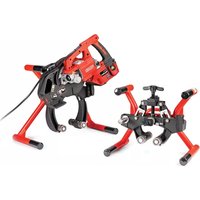
| Main use | Drilling holes in steel pipes (up to 3") |
| Included accessories | Chuck key, base, motor |
| Safety | Ground fault circuit interrupter, mandatory eye protection |
| Maintenance | Cleaning, lubrication, brush replacement, adjustment of set screws |
| Storage | Indoors, out of reach of children and untrained persons |
| Warranty | Lifetime warranty (Full Lifetime Warranty) |
Frequently Asked Questions - HC300 RIDGID
User questions about HC300 RIDGID
0 question about this device. Answer the ones you know or ask your own.
Ask a new question about this device
Download the instructions for your Saw in PDF format for free! Find your manual HC300 - RIDGID and take your electronic device back in hand. On this page are published all the documents necessary for the use of your device. HC300 by RIDGID.
USER MANUAL HC300 RIDGID
natural_image
Two industrial drilling machines with red seals, one with a chain link and the other with a gear mechanism (no visible text or symbols)


RIDGID.com/qr/hc300RIDGID.com/qr/hc450

EN
P.
[Non-Text]
1
FR
P. 13
ES
P. 27
DE
P. 41
NL
P. 55
IT
P. 69
PT
P. 83
SV
P. 97
DA
P. 111
NO
P. 125
FI
P. 139
PL
P. 153
CZ
P. 167
SK
P. 181
RO
P. 195
HU
P. 209
EL
P. 223
HR
P. 239
SL
P. 253
SR
P. 267
RU
P. 281
TR
P. 297
KK
P. 311
Table of Contents
Recording Form For Machine Serial Number 1
Safety Symbols....2
General Safety Rules
Work Area 2
Electrical Safety....2
Personal Safety....3
Tool Use and Care ....3
Service 3
Hole Cutter Safety Warnings....3
Model HC-450 Description, Specifications and Standard Equipment
Description 4
Specifications 4
Standard Equipment....4
Model HC-300 Description, Specifications and Standard Equipment
Description 5
Specifications 5
Standard Equipment....5
Icons 5
Pre-Operation Inspection....6
Machine And Work Are Set-Up....7
Mounting The Hole Cutting Tool On The Pipe
HC-450....8
HC-300 8
Powering the Hole Cutting Tool....9
Operating Instructions....10
Maintenance Instructions
Cleaning 11
Lubrication....11
Changing brushes....11
Gib Screw Adjustment....11
Accessories 11
Machine Storage....12
Service and Repair 12
Disposal....12
EU Declaration of Conformity ....Inside Back Cover
Lifetime Warranty....Back Cover
*Original Instructions - English
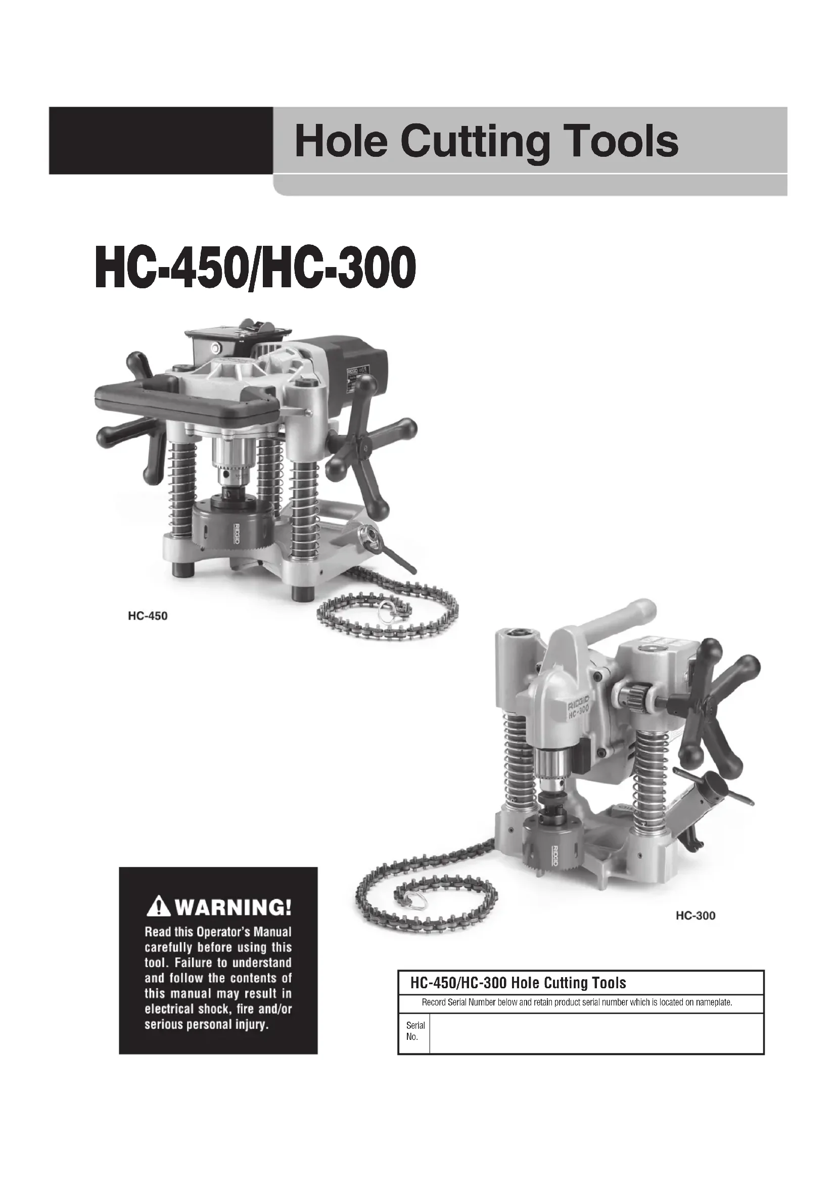
Hole Cutting Tools
HC-450/HC-300

natural_image
Mechanical drilling rig with helical base and mechanical components, labeled HC-450 (no readable text or symbols on the device itself)
natural_image
Industrial CNC machine with helical base and chain links, no visible text or symbols on the device itself.WARNING!
Read this Operator's Manual carefully before using this tool. Failure to understand and follow the contents of this manual may result in electrical shock, fire and/or serious personal injury.
HC-450/HC-300 Hole Cutting Tools
| Record Serial Number below and retain product serial number which is located on nameplate. | |
| Serial No. | |
Safety Symbols
In this operator's manual and on the product, safety symbols and signal words are used to communicate important safety information. This section is provided to improve understanding of these signal words and symbols.

This is the safety alert symbol. It is used to alert you to potential personal injury hazards. Obey all safety messages that follow this symbol to avoid possible injury or death.

DANGER
DANGER indicates a hazardous situation which, if not avoided, will result in death or serious injury.

WARNING
WARNING indicates a hazardous situation which, if not avoided, could result in death or serious injury.

CAUTION
CAUTION indicates a hazardous situation which, if not avoided, could result in minor or moderate injury.
NOTICE
NOTICE indicates information that relates to the protection of property.

This symbol means read the operator's manual carefully before using the equipment. The operator's manual contains important information on the safe and proper operation of the equipment.

This symbol means always wear safety glasses with side shields or goggles when handling or using this equipment to reduce the risk of eye injury.

This symbol indicates the risk of fingers, hands, clothes and other objects catching on or between gears or other rotating parts and causing crushing injuries.

This symbol indicates the risk of hands, fingers or other body parts being cut by the blade.

This symbol indicates the risk of electrical shock.

This symbol means do not wear gloves while operating this machine to reduce the risk of entanglement.

This symbol means wear a hard hat when working overhead to reduce the risk of head injury.
General Safety Rules\*
WARNING
Read and understand all instructions. Failure to follow all instructions listed below may result in electric shock, fire, and/or serious injury.
SAVE THESE INSTRUCTIONS!
Work Area
- Keep work area clean and well lit. Cluttered benches and dark areas invite accidents.
- Do not operate power tools in explosive atmospheres, such as in the presence of flammable liquids, gases, or dust. Power tools create sparks which may ignite the dust or fumes.
- Keep bystanders, children, and visitors away while operating a power tool. Distractions can cause you to lose control.
Electrical Safety
- Grounded tools must be plugged into an outlet properly installed and grounded in accordance with all codes and ordinances. Never remove the
grounding prong or modify the plug in any way. Do not use any adapter plugs. Check with a qualified electrician if you are in doubt as to whether the outlet is properly grounded. If the tool should electrically malfunction or break down, grounding provides a low resistance path to carry electricity away from the user.
- Avoid body contact with grounded surfaces such as pipes, radiators, ranges and refrigerators. There is an increased risk of electric shock if your body is grounded.
- Do not expose power tools to rain or wet conditions. Water entering a power tool will increase the risk of electric shock.
- Do not abuse the cord. Never use the cord to carry the tool or pull the plug from an outlet. Keep cord away from heat, oil, sharp edges or moving parts. Replace damaged cords immediately. Damaged cords increase the risk of electric shock.
- When operating a power tool outside, use an outdoor extension cord marked "W-A" or "W". These
cords are rated for outdoor use and reduce the risk of electric shock.
Personal Safety
- Stay alert, watch what you are doing and use common sense when operating a power tool. Do not use a tool while you are tired or under the influence of drugs, alcohol or medication. A moment of inattention while operating power tools may result in serious personal injury.
- Dress properly. Do not wear loose clothing or jewelry. Contain long hair. Keep your hair, clothing and gloves away from moving parts. Loose clothes, jewelry or long hair can be caught in moving parts.
- Avoid accidental starting. Be sure switch is OFF before plugging in. Carrying power tools with your finger on the switch or plugging in power tools that have the switch ON invites accidents.
- Remove adjusting keys or wrenches before turning the tool ON. A wrench or a key left attached to a rotating part of the power tool may result in personal injury.
- Do not overreach. Keep proper footing and balance at all times. Proper footing and balance enables better control of the tool in unexpected situations.
- Use safety equipment. Always wear eye protection. Safety equipment such as dust mask, non-skid safety shoes, hard hat, or hearing protection used for appropriate conditions will reduce personal injuries.
Tool Use and Care
- Use clamps or other practical way to secure and support the workpiece to a stable platform. Holding the work by hand or against your body is unstable and may lead to loss of control.
- Do not force the tool. Use the correct tool for your application. The correct tool will do the job better and safer at the rate for which it was designed.
- Do not use the power tool if the switch does not turn it ON and OFF. Any tool that cannot be controlled with the switch is dangerous and must be repaired.
- Disconnect the plug from the power source before making any adjustments, changing accessories, or storing power tools. Such preventive safety measures reduce the risk of starting the power tool accidentally.
-
Store idle tools out of the reach of children and other untrained persons. Tools are dangerous in the hands of untrained users.
-
Maintain tools with care. Keep cutting tools sharp and clean. Properly maintained tools with sharp cutting edges are less likely to bind and are easier to control.
- Check for misalignment or binding of moving parts, breakage of parts and any other condition that may affect the tool's operation. If damaged, have the tool serviced before using. Many accidents are caused by poorly maintained tools.
- Use only accessories that are recommended by the manufacturer for your model. Accessories that may be suitable for one tool, may become hazardous when used on another tool.
Service
- Tool service must be performed only by qualified repair personnel. Service or maintenance performed by unqualified personnel could result in a risk of injury.
- When servicing a tool, use only identical replacement parts. Follow instructions in the Maintenance section of this manual. Use of unauthorized parts or failure to follow Maintenance Instructions may create a risk of electrical shock or injury.
Hole Cutter Safety Warnings
WARNING
This section contains important safety information that is specific to this tool.
Read these precautions carefully before using this Hole Cutting Tool to reduce the risk of electrical shock or other serious personal injury.
SAVE ALL WARNINGS AND INSTRUCTIONS FOR FUTURE REFERENCE!
Keep this manual with the machine for use by the operator.
- Always wear appropriate eye protection. Cutting tools can break or shatter. Cutting produces chips that can be thrown or fall into eyes.
- Do not wear gloves or loose clothing when operating machine. Keep Sleeves and jackets buttoned. Do not reach across machine. Clothing can be caught by the machine resulting in entanglement.
- Keep fingers and hands away from rotating chuck and saw. This reduces the risk of entanglement and cutting injuries.
-
Properly secure the Hole Cutting Tool to the pipe. Improperly secured Hole Cutting Tools can fall and cause striking and crushing injuries.
-
Do not use for hot tapping. When cutting into an existing system, the pipe must be drained and depressurized prior to cutting. This reduces the risk of electrical shock and other serious injury.
- Before using, test the Ground Fault Circuit Interrupter (GFCI) provided with the power cord to insure it is operating properly. GFCI reduces the risk of electrical shock.
- When working overhead, all personnel should wear hard hats and be clear of the area below the tool. This reduces the risk of serious injury should objects fall.
- Only use Hole Cutting Tools to cut holes in pipe as directed in this manual. Do not use for other purposes or modify. Other uses or modifying this tool for other purposes may increase the risk of serious injury.
Read and understand the instructions and warnings for all equipment being used before operating the Hole Cutting Tool. Failure to follow all instructions and warnings may result in property damage or serious personal injury.
WARNING Some dust created by power sanding, sawing, grinding, drilling and other construction activities contains chemicals known to cause cancer, birth defects, or other reproductive harm. Some examples of these chemicals are:
- Lead from lead based paint
- Crystalline silica from bricks and cement and other masonry products, and
- Arsenic and chromium from chemically treated lumber
Your risk from these exposures varies, depending on how often you do this type of work. To reduce your exposure to these chemicals: work in a well ventilated area, and work with approved safety equipment, such as those dust masks that are specifically designed to filter out microscopic particles.
If you have any question concerning this RIDGID® product:
- Contact your local RIDGID distributor.
- Visit RIDGID.com or RIDGID.eu to find your local RIDGID contact point.
- Contact Ridge Tool Technical Service Department at ProToolsTechService@Emerson.com, or in the U.S. and Canada call 844-789-8665.
Model HC-450 Description, Specifications And Standard Equipment
Description
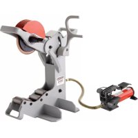
The RIDGID® Model HC-450 Hole Cutting Tool is designed to cut holes up to 4 ^3/4 " into steel pipe. The multiple hole sizes allow the use of Mechanical T's®, Hookers®, Vic-O-Lets™, and other fittings for branching unpressurized pipe lines.
The HC-450 has a 58 " capacity drill chuck to accommodate all sizes of hole saws and hole saw arbors. An integral motor and gear reduction optimizes performance of large diameter hole saws. The two feed handles allows the operator to use the Hole Cutting Tool from either the left or right side. A rotating leveling vial in the base allows repeated holes to line up. Only 13" high, the compact design, allows the HC-450 to be used in tight quarters or above installed pipe close to ceilings.
NOTE! Mechanical T's, Hookers, and Vic-O-Lets are registered trademarks of Victaulic Tool Company
Specifications
Cutting Capacity ....Up to 4 ^3/4 " (120 mm)
Pipe Mounting
Capacity 1 ^1/4 " - 8" (30mm-200 mm)
Drill Chuck Capacity .....1/16" - 5/8" (2mm-16 mm)
Drill Chuck Speed.....110 RPM
Motor Horsepower.....1.2 HP
Current Draw Rating.....12 Amps @ 120V
6 Amps @ 220-240V
12 Amps @ 100V
Sound Pressure ( L_PA )* .....97.4 dB(A), K=3
Sound Power (LWA)*......101.43 dB(A), K=3
* Sound measurements are measured in accordance with a standardized test per Standard EN 62841-1.
- Sound emissions may vary due to your location and specific use of these tools.
- Daily exposure levels for sound need to be evaluated for each application and appropriate safety measures taken when needed. Evaluation of exposure levels should consider the time a tool is switched off and not in use. This may significantly reduce the exposure level over the total working period.
Dimensions
Height 12.62" (29 cm)
Length 17" (43 cm)
Width 17" (43 cm)
Weight 42 lbs. (19 Kg)
Standard Equipment
- Hole Cutting Tool
- Chuck Key
- ^5/8 " Hole Saw Arbor w/Backing Plate and ^1/4 " Pilot Drill

Figure 1 – HC-450 with Standard Equipment
Model HC-300 Description, Specifications And Standard Equipment
Description
The RIDGID® Model HC-300 Hole Cutting Tool is designed to cut holes up to 3" diameter into steel pipe. The multiple hole size allows the use of Mechanical T's®, Hookers®, Vic-O-Lets™, Weld-O-Let™ and other fittings for branching unpressurized pipelines.
The HC-300 features a 12 " capacity chuck to accommodate all size of holes up to 3" diameter and standard hole saw arbors up to 716 " Hex ( 12 " chuck size). An integral motor and gear reduction optimizes the performance and saw life in the capacity range. A single feed handle and ON/OFF switch allows for easy operation. The compact two-piece design allows the HC-300 to be used in tight quarters and difficult-to-reach locations.
NOTE! Mechanical T's, Hookers, and Vic-O-Lets are registered trademarks of Victaulic Tool Company.

Figure 2 – Model HC-300 with Standard Equipment
Specifications
Cutting Capacity ....Up to 3" (76mm)
Pipe Mounting
Capacity ....1 ^1/4 " - 8" (30mm-200mm)
Drill Chuck Capacity ..... ^1/16 " - ^1/2 " (2mm-13mm)
Drill Chuck Speed......360 RPM
Motor Horsepower.....1.2 HP
Current Draw Rating.....11 Amps @ 120V
5.5 Amps @ 220-240V
12 Amps @ 100V
Sound Pressure (L _PA )* .....97.4 dB(A), K=3
Sound Power (LWA)*......101.43 dB(A), K=3
* Sound measurements are measured in accordance with a standardized test per Standard EN 62841-1.
- Sound emissions may vary due to your location and specific use of these tools.
- Daily exposure levels for sound need to be evaluated for each application and appropriate safety measures taken when needed. Evaluation of exposure levels should consider the time a tool is switched off and not in use. This may significantly reduce the exposure level over the total working period.
Dimensions
Height 12.8" (32.5 cm)
Length 11.9" (30.2 cm)
Width 13.2" (33.4 cm)
Total Weight ......31 lbs. (14 kg)
Base 10 lbs. (4.5 kg)
Motor Assembly.....21 lbs. (9.5 kg)
Standard Equipment
• Hole Cutting Tool (Base and Motor Assembly)
- Chuck Key

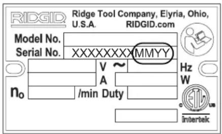
Figure 3 – Machine Serial Number
For both the HC-450 and HC-300 Hole Cutter Tool, the serial number is located on the underside of the motor. The last 4 digits indicates the month and year of the manufacture (MMYY).
Icons


NOTICE Selection of appropriate materials and installation, joining and forming methods is the responsibility of the system designer and/or installer. Selection of improper materials and methods could cause system failure.
Stainless steel and other corrosion resistant materials can be contaminated during installation, joining and forming. This contamination could cause corrosion and premature failure. Careful evaluation of materials and methods for the specific service conditions, including chemical and temperature, should be completed before any installation is attempted.
Pre-Operation Inspection
WARNING
Before each use, inspect your Hole Cutting Tool and correct any problems to reduce the risk of serious injury from electric shock and other causes and prevent tool damage.
- Make sure that the Hole Cutting Tool is unplugged and the ON/OFF switch is in the OFF position.
- Clean any oil, grease or dirt from the tool, including the handles and controls. This aids inspection and helps prevent the tool or control from slipping from your grip.
-
Inspect the Hole Cutting Tool for the following items:
-
Inspect the power cord, Ground Fault Circuit Interrupter (GFCI) and plug for damage or modification.
• Proper assembly and completeness. - Broken, worn, missing, mis-aligned or binding parts. Make sure that the motor assembly moves smoothly and freely up and down the posts of the base assembly. Confirm that the chain and swivel handle move freely. On the HC-300, confirm that the plunger pin functions properly and retains the motor assembly to the base assembly (Figure 7).

natural_image
Industrial machine with coiled springs and a handle, no visible text or symbolsFigure 4A – HC-450 Warning Label

natural_image
Close-up of a mechanical pressure relief device with coiled spring and attached control panel (no visible text or symbols)Figure 4B - HC-300 Warning Labels
• Presence and readability of the warning labels (see Figures 4A and 4B).
- Any other condition which may prevent safe and normal operation.
If any problems are found, do not use the hole cutting tool until the problems have been repaired.
- Inspect the arbor, hole saw and drills to be used with the Hole Cutting Tool for wear, deformation, breakage or other issues. Do not use dull or damaged cutting tools. Dull or damaged cutting tools increase the amount of force required, produce poor quality cuts and increase the risk of injury.
-
With dry hands, plug the cord in. Test the GFCI in the electrical cord to insure that it is operating correctly. When the test button is pushed in, the reset button should pop out. Reactivate by pushing the reset button. If the GFCI is not functioning properly, unplug the cord and do not use the hole cutting tool until the GFCI has been repaired.
-
With the Hole Cutting Tool on a stable surface check the Hole Cutting Tool for proper operation. Keep clear of the chuck. Move the ON/OFF switch to the ON position. The motor should start and the chuck turn counter clockwise viewed from the chuck end. Inspect the tool for misalignment, binding, odd noises or other unusual conditions. Move the ON/OFF switch to the OFF position. If any issues are found, do not use the tool until it has been repaired.
- After the inspection is complete, with dry hands unplug the tool.
Machine And Work Area Set-Up
WARNING


Set up the Hole Cutting Tool and work area according to these procedures to reduce the risk of injury from electrical shock, entanglement, crushing and other causes and prevent tool damage.
Properly secure the Hole Cutting Tool to the pipe. Improperly secured Hole Cutting Tools can slip and fall and cause striking and crushing injuries.
Do not use for hot tapping. When cutting into an existing system, the pipe must be drained and depressurized prior to cutting. This reduces the risk of electrical shock and other serious injuries.
When working overhead, all personnel should wear hard hats and be clear of the area below. This reduces the risk of serious injury should equipment or other objects fall.
-
Check work area for:
-
Adequate lighting.
- Flammable liquids, vapors or dust that may ignite. If present, do not work in area until sources have been identified and corrected. The hole cutter is not explosion proof and can cause sparks.
- Clear, level, stable, dry location for all of the equipment and operator.
- Properly grounded electrical outlet of the correct voltage. A three prong or GFCI outlet may not be properly grounded. If in doubt, have outlet inspected by a licensed electrician.
-
Clear path to electrical outlet that does not contain any potential sources of damage for the power cord.
-
Inspect the work to be done. Determine the pipe type and size, and clearance around the pipe. Determine
the size and location of the hole to be cut. Clearly mark the cut location. If installing a fitting, follow the fitting manufacturer's instructions. Determine the correct equipment for the job. See the Description and Specification sections for tool information.
Make sure that the pipe to be cut is well supported and stable. The pipe must be able to handle the weight of the Hole Cutting Tool and the forces applied during cutting without moving.
If working on an existing system, make sure that the system has been depressurized and drained. The Hole Cutting Tools are not designed for hot tapping purposes. Cutting into pressurized or systems with fluids in them can cause spills, electrical shock and other serious injury. Know the contents of the pipe and any specific hazards associated with the contents.
- Confirm that the equipment to be used has been properly inspected,
- Select an appropriate hole saw for the work to be performed. Make sure that the hole saw is properly assembled per its instructions and is in good working order. The use of a pilot drill is recommended. The pilot drill should extend no more than 3/8" (10mm) past the end of the hole saw, and should be securely tightened.
- With the Hole Cutting Tool on a stable surface, install the hole saw into the chuck. Always make sure that the ON/OFF switch is in the OFF position and the Hole Cutting Tool is unplugged before installing or changing the hole saw or drill.
- Open the chuck wide enough for the shank of the hole saw. If needed, the chuck key can be used to open the chuck. Make sure that the shank and the chuck jaws are clean.
- Fully insert the shank into the chuck. Make sure that the hole saw is centered in the chuck and firmly tighten the chuck by hand.
- Use the chuck key in all three chuck holes to securely tighten the chuck onto the shank. Make sure to remove the chuck key from the chuck before turning the tool ON.
Mounting The Hole Cutting Tool On The Pipe
Hole Cutting Tools weigh up to approximately 42 pounds. Use good lifting technique when placing on the pipe, do not overreach, and keep good balance and footing at all times. Depending on the circumstances, two people may be necessary to mount the Hole Cutting Tool onto the pipe.
Hole Cutting Tools can be used at any angle or orientation. If cutting a hole on the side or bottom of a pipe, it may be easier to place the Hole Cutting Tool on the top of the pipe to fasten the chain around the pipe and then move the Hole Cutting Tool into final position.
HC-450
-
Make sure the chain is hanging freely and the swivel handle is fully loosened.
-
Carefully lift the HC-450 Hole Cutting Tool and place with the V-shaped guides squarely on the pipe near the location of the cut. Make sure the chain is not between the pipe and tool base.
-
Always keep at least one hand on the Hole Cutting Tool to stabilize and guide it. Grasp the end of the chain and pull it snugly around the pipe. Hook the closest chain pin on the wear plate and firmly tighten the swivel handle to hold the Hole Cutting Tool to the pipe. (See Figure 5)

Figure 5 – Hooking the HC-450 Chain
- The base of the HC-450 Hole Cutting Tool includes a level vial that can be used to align a series of holes. When the Hole Cutting Tool is placed at the desired angle, the vial can be rotated to the level position, and subsequent holes can be made at the same angle by leveling the Hole Cutting Tool with the vial. (See Figure 6)

natural_image
Close-up of a mechanical component with a central circular feature and threaded shaft (no visible text or symbols)Figure 6 – HC-450 Hole Cutting Tool Level Vial
- With one hand on the Hole Cutting Tool to stabilize and guide it, slightly loosen the swivel handle to allow final positioning of the tool. Align the pilot drill with the desired cut location, and firmly tighten the swivel handle. Do not remove your hands from the Hole Cutting Tool until you have confirmed that it is securely attached to the pipe. The Hole Cutting Tool must be securely and squarely attached to the pipe to help reduce the risk of hole saw jamming.
HC-300
The HC-300 can be mounted on the pipe either as a complete unit (similar to the HC-450) or by separating the base assembly from the tool, mounting the base to the pipe, and then installing the motor assembly to the base assembly.
- With the HC-300 Hole Cutting Tool on a stable, secure surface, pull the plunger on the back of the left post (Figure 7) and lift the motor assembly off of the base assembly.

Figure 7 – Separating the Base and Motor Assemblies
-
Make sure the chain is hanging freely and the swivel handle is fully loosened on the base assembly.
-
Place the base assembly with the V-shaped guides squarely on the pipe near the location of the cut. Make sure the chain is not between the pipe and tool base.
-
Always keep at least one hand on the base assembly to stabilize and guide it. Grasp the end of the chain and pull it snugly around the pipe. As you pull on the chain, a spring is compressed at the attachment end of the chain. Hook the closest chain pin on the chain hook – the spring tension will help keep the chain engaged with the chain hook. Firmly tighten the crank screw assembly to hold the base assembly to the pipe. (See Figure 8.)

natural_image
Close-up of hands operating a mechanical clamp or clamping device on a cylindrical pipe (no visible text or symbols)Figure 8 – Hooking the Chain
- Carefully lift the motor assembly and align the post openings in the motor assembly with the posts of the base assembly. Press the motor assembly on until the plunger engages the post to retain the motor assembly to the base. Confirm that the motor assembly is securely attached to the base. See Figure 9.
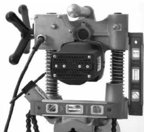
- The base of the HC-300 includes several machined flats for use with levels for hole alignment. See Figure 10.

natural_image
Close-up of a hand operating a high-speed drill press machine (HD-300) with visible spring and screw base, no text or symbols present.Figure 9 – Attaching the HC-300 Motor Assembly to the Base Assembly

natural_image
Mechanical device with spring and mounting bracket (no visible text or symbols)Figure 10 - HC-300 Leveling
- With one hand on the Hole Cutting Tool to stabilize and guide it, slightly loosen the crank screw assembly to allow final positioning of the tool. Align the pilot drill with the desired cut location, and firmly tighten the crank screw assembly. Do not remove your hands from the Hole Cutting Tool until you have confirmed that it is securely attached to the pipe. The Hole Cutting Tool must be securely and squarely attached to the pipe to help reduce the risk of hole saw jamming.
To mount the HC-300 on the pipe as a complete unit, follow the steps indicated in the HC-450 section, using the information in the HC-300 section on chain hooking and alignment.
Powering the Hole Cutting Tool
- Confirm that the ON/OFF switch is in the OFF position.
-
Makes sure that the power cord is routed out the back of the tool away from the chuck and work area. Run the cord along the clear path to the outlet, and with dry hand plug in. Keep all connections dry and off the ground. If the power cord is not long enough, use an extension cord that:
-
Is in good condition
- Has a three prong plug similar to that on the tool.
- Is rated for outdoor use and contains a W or W-A in the cord designation (i.e. SOW), or complies with H05VV-F, H05RN-F types or IEC type design (60227 IEC 53, 60245 IEC 57).
- Has sufficient wire size (16 AWG (1.5mm ^2 ) for 50' (15.2m) or less, 14 AWG (2.5mm ^2 ) for 50' - 100' (15.2m - 30.5m) long). Undersized wires can overheat, melting the insulation or causing a fire or other damage.
When using an extension cord, the GFCI on the Hole Cutting Tool does not protect the extension cord. If the outlet is not GFCI protected, it is advisable to use a plug in type GFCI between the outlet and the extension cord to reduce the risk of shock if there is a fault in the extension cord.
Operating Instructions
WARNING


Always wear appropriate eye protection. Cutting tools can break or shatter. Cutting produces chips that can be thrown or fall into eyes.
Do not use for hot tapping. When cutting into an existing system, the pipe must be drained and depressurized prior to cutting. This reduces the risk of electrical shock and other serious injury.
Do not wear gloves or loose clothing when operating machine. Keep Sleeves and jackets buttoned. Do not reach across machine. Clothing can be caught by the machine resulting in entanglement.
Keep fingers and hands away from rotating chuck and saw. This reduces the risk of entanglement and cutting injuries.
Follow operating instructions to reduce the risk of injury from electrical shock entanglement, crushing and other causes and prevent Hole Cutter damage.
- Confirm that the Hole Cutting Tool and work area are properly set up and that the work area is free of bystanders and other distractions.
- Assume a proper operating position that will allow:
- Control of the Hole Cutting Tool, including the ON/OFF switch and the feed handle. On the HC-300 you must be on the same side as the switch and the feed handle. Do not turn the tool ON yet
- Good balance. Be sure that you do not have to over reach.
-
Move the ON/OFF switch to the ON position. Observe the rotation of the hole saw and pilot drill, making sure it is running straight and true. If they wobble, or any other issues are noted, move the switch to OFF and unplug tool, fix any issues prior to using. Keep fingers, hands and clothes away from the turning chuck to help reduce the risk of entanglement.
-
Place both hands on the hand wheel and advance the pilot drill into contact with the pipe. Apply firm pressure, and start drilling the pilot hole. Do not force the pilot drill/hole saw. This can overload the hole saw and the tool motor and cause premature failure.

natural_image
Close-up of a hand operating a mechanical presser or drill bit assembly (no visible text or symbols)Figure 11 – Operating the Hole Cutting Tool
Once the hole saw is in contact with the pipe, continue to apply firm pressure. Depending on the size and wall thickness of the pipe and the size of the hole being cut, the hole saw may need to be retracted slightly at times for chip removal.
If needed, the Hole Cutting Tool can be shut off and a small amount of appropriate cutting lubricant applied to the work piece. Do not apply lubricant while the tool is running, this increases the risk of entanglement. Take appropriate steps to prevent the lubricant from dripping or being thrown during use.
As the hole saw moves through the pipe and as the cut is completed, there will be an interrupted cut at times. Decrease pressure as this occurs to help prevent jamming of the hole saw.
- Once the hole is complete, retract the hole saw from the pipe and turn the ON/OFF switch OFF.
- Reverse the mounting procedure to remove the Hole Cutting Tool from the pipe. Make sure you have secure grip on the Hole Cutting Tool prior to loosening the chain or pulling the plunger on the HC-300.
- If the pipe slug needs to be removed from the hole saw, always make sure that the ON/OFF switch is in the OFF position and the Hole Cutting Tool is unplugged before removing. Remove the slug with care, the slug may be hot and edges can be sharp.
Maintenance Instructions
WARNING
Make sure that the ON/OFF switch is in the OFF position and the tool is unplugged before performing any maintenance or making any adjustments.
Maintain tool according to these procedures to reduce the risk of injury from electrical shock, entanglement and other causes.
Cleaning
After each use, wipe any chips or oil off with a soft, clean, damp cloth, especially areas of relative motion such as the posts. Clean any dust and debris from the motor vents.
Lubrication
The Hole Cutting Tools gearboxes are designed as sealed systems, and should not require any additional grease unless significant leakage has occurred. In those cases, the tools should be returned to a service center.
Do not lubricate the bearings that ride on the posts. The bearings are not designed to be used with lubricants, and lubricants will hold dirt and debris that could damage the bearings.
As needed, the chain and screw assemblies can be lubricated with a light lubricating oil. Wipe any excess oil from exposed surfaces.
Changing Brushes
Check motor brushes every six months and replace when worn to less than 12 .
- Remove four screws holding motor cover, remove cover.
- Using a pair of pliers, pull the motor brushes straight out. Detach the connector. (See Figure 12)

Figure 12 – Brush Placement - Motor Cover Removed
-
Inspect the commutator for wear. If excessively worn, have tool serviced.
-
Depress the brush into the holder and insert into the motor housing. Inspect to make sure insulator sheets are properly positioned between brush holder and housing. Attach the connector and replace the motor cover.
Gib Screw Adjustment
Gib screws are provided on the HC-450 to allow adjustment of the drag between the base and motor assemblies. Tighten or loosen the Gib screws to adjust as desired. (See Figure 13)

Figure 13 – Adjusting Gib Screws
Accessories
WARNING
To reduce the risk of serious injury, only use accessories specifically designed and recommended for use with the RIDGID Hole Cutting Tools, such as those listed below. Other Accessories suitable for use with other tools may be hazardous when used with the RIDGID Hole Cutting Tools.
Model HC-300
| Catalog No. | Description |
| 16671 | R2S Solid Shank Arbor |
| 84427 | HC-450/HC-300 Carrying Case |
| 77017 | Chuck Key |
Model HC-450
| Catalog No. | Description |
| 84427 | HC-450 Carry Case |
| 59502 | R4 5/8" Arbor only for Hole Saws |
| 59132 | Chuck Key |
See RIDGID catalog for listing of Hole Saws.
Machine Storage
WARNING The Hole Cutting Tool must be kept indoors or well covered in rainy weather. Store the machine in a locked area that is out of reach of children and people unfamiliar with hole cutting tool. This machine can cause serious injury in the hands of untrained users.
Service and Repair
WARNING
Improper service or repair can make machine unsafe to operate.
The “Maintenance Instructions” will take care of most of the service needs of this machine. Any problems not addressed by this section should only be handled by an authorized RIDGID service technician.
Tool should be taken to a RIDGID Authorized Independent Service Center or returned to the factory.
For information on your nearest RIDGID Authorized Independent Service Center or any service or repair questions:
- Contact your local RIDGID distributor.
- Visit RIDGID.com or RIDGID.eu to find your local Ridge Tool contact point.
- Contact Ridge Tool Technical Service Department at ProToolsTechService@Emerson.com, or in the U.S. and Canada call 844-789-8665.
Disposal
Parts of the Hole Cutting Tool contain valuable materials and can be recycled. There are companies that specialize in recycling that may be found locally. Dispose of the components in compliance with all applicable regulations. Contact your local waste management authority for more information.

For EC Countries: Do not dispose of electrical equipment with household waste!
According to the European Guideline 2002/ - 96/ EC for Waste Electrical and Electronic Equipment and its implementation into national legislation, electrical equipment that is
no longer usable must be collected separately and disposed of in an environmentally correct manner.
Scies à cloche
HC-450/HC-300

natural_image
Mechanical drilling rig with helical base and mechanical components (no visible text or symbols)
natural_image
Industrial CNC machine with helical base and spring components, no visible text or symbols on the device itself.
AVERTISSEMENT
natural_image
Mechanical device with springs and a handle, no visible text or symbolsnatural_image
Close-up of a mechanical pressure relief device with coiled spring and attached control panel (no visible text or symbols)natural_image
Close-up of a mechanical component with a central circular feature and threaded shaft (no visible text or symbols)natural_image
Close-up of hands operating a mechanical clamp or fixture with two threaded components mounted on a cylindrical pipe (no visible text or symbols)natural_image
Close-up of a hand operating a DODID HC-300 drill press with spring and handle (no visible text or symbols)natural_image
Close-up of a mechanical device with springs and control panel (no visible text or symbols)natural_image
Close-up of a hand operating a mechanical drilling or milling machine tool (no visible text or symbols)natural_image
Mechanical drilling rig with helical base and mechanical components, labeled HC-450 (no readable text or symbols on the device itself)
natural_image
Black-and-white photo of a Mitsubishi HC-300 CNC milling machine with coiled tracks and no visible text or symbols on the device itself.
ADVERTENCIA
Peso 42 lbs. (19 Kg.)
Equipo estándar
Total Weight ......31 lbs. (14 Kg.)
Base 10 lbs. (4,5 Kg.)
Motor ......21 lbs. (9,5 Kg.)
Equipo estándar
• Perforadora (base y motor)
- Llave del portabrocas
natural_image
Mechanical device with springs and a control panel, no visible text or symbolsnatural_image
Close-up of a mechanical hydraulic or pneumatic device with hoses and a control panel (no visible text or symbols)natural_image
Close-up of a mechanical component with a central circular feature and threaded shaft (no visible text or symbols)Figura 6 – Tubito del nivel de la Perforadora HC-450
natural_image
Close-up of hands operating a mechanical clamp or clamping tool on a cylindrical object (no visible text or symbols)natural_image
Close-up of a hand operating a CNC drilling press with spring scales and a handle (no visible text or symbols)natural_image
Close-up of a mechanical device with springs and connectors (no visible text or symbols)natural_image
Close-up of a hand operating a mechanical presser or drill bit machine (no visible text or symbols)natural_image
Mechanical drilling rig with helical base and mechanical components, no visible text or symbols on the device itself.
natural_image
Industrial CNC machine with helical base and mechanical components, no visible text or symbols on the device itself.WARNING!
natural_image
Mechanical device with springs and a head handle, no visible text or symbolsAbbildung 4A – HC-450 Warnaufkleber

natural_image
Close-up of a mechanical pressure relief device with coiled spring and attached control panel (no visible text or symbols)natural_image
Close-up of a mechanical component with a circular target and threaded base (no visible text or symbols)natural_image
Close-up of hands operating a mechanical clamp or clamping tool on a cylindrical pipe (no text or symbols visible)natural_image
Close-up of hands operating a RIGG10 HC-300 drill press with spring and handle (no visible text or symbols)natural_image
Close-up of a mechanical device with springs and connectors (no visible text or symbols)Abbildung 10 – HC-300 Nivellieren
natural_image
Close-up of a hand operating a mechanical presser or drill bit machine (no visible text or symbols)natural_image
Mechanical drilling rig with attached gear and chain link (no visible text or symbols)
natural_image
RICHOLI HC-300 mechanical tool with coiled track and mounting bracket (no visible text or symbols)⚠ WAARSCHUWING!
natural_image
Industrial machine with coiled springs and a chain, no visible text or symbolsnatural_image
Close-up of a mechanical pressure relief device with coiled spring and attached control panel (no visible text or symbols)natural_image
Two black-and-white pictograms: one showing a person with an arrow, the other showing a person holding a pointer (no text or symbols)natural_image
Close-up of a mechanical component with a circular cross-section and directional arrows, no visible text or symbols.natural_image
Close-up of hands operating a mechanical clamp or fixture with a cylindrical component and coiled chains (no visible text or symbols)natural_image
Close-up of a hand operating a RIGD HC-300 drill press machine with coiled springs and a handle (no visible text or symbols)natural_image
Close-up of a mechanical device with springs and control panel (no visible text or symbols)natural_image
Close-up of a hand operating a mechanical presser or clamp assembly (no visible text or symbols)natural_image
Mechanical drilling rig with attached gear and chain link (no visible text or symbols)
natural_image
Mechanical tool with springs and a propeller, displayed against a plain background (no text or symbols visible)ATTENZIONE!
natural_image
Industrial machine with coiled springs and a mechanical handle, no visible text or symbolsnatural_image
Close-up of a mechanical device with coiled spring and attached control panel (no visible text or symbols)natural_image
Close-up of a mechanical component with a circular crosshair and directional arrows, no visible text or symbols.Figure 6 – Livella del Foratubi HC-450
natural_image
Close-up of hands operating a mechanical clamp or clamping device on a black cylindrical component (no visible text or symbols)natural_image
Close-up of a hand operating a RIGD10 HC-300 drill press with spring and connecting components (no visible text or symbols)natural_image
Close-up of a mechanical device with coiled springs and control panel (no visible text or symbols)natural_image
Close-up of a hand operating a mechanical presser or drill bit with spring and cylindrical components (no visible text or symbols)natural_image
Mechanical drilling rig with attached spring and chain link components (no visible text or symbols)
natural_image
Rico HC-300 mechanical tool with coiled track and spring components (no visible text or symbols)AVISO!
Figura 3 – Número de série da máquina
natural_image
Industrial machine with coiled springs and a mechanical handle, no visible text or symbolsFigura 4A – Etiqueta de aviso da HC-450

natural_image
Close-up of a mechanical device with coiled spring and attached control panel (no visible text or symbols)Figura 4B – Etiquetas de aviso da HC-300
natural_image
Close-up of a mechanical component with a circular crosshair and threaded rod (no visible text or symbols)natural_image
Close-up of hands operating a mechanical clamp or fixture with a cylindrical component (no visible text or symbols)natural_image
Close-up of a hand operating a Riddi HC-300 drill press with coiled springs and a handle (no visible text or symbols)natural_image
Close-up of a mechanical device with springs and connectors (no visible text or symbols)Figura 10 - Nivelamento da HC-300
natural_image
Close-up of a hand operating a mechanical presser or drill bit machine (no visible text or symbols)natural_image
Mechanical drilling rig with attached gear and chain link (no visible text or symbols)
natural_image
Industrial CNC machine with helical base and spring components, no visible text or symbols on the device itself.WARNING!
Figur 3 – Maskinens serienummer
natural_image
Industrial machine with coiled springs and a mechanical handle, no visible text or symbolsnatural_image
Close-up of a mechanical pressure relief device with coiled spring and attached control panel (no visible text or symbols)Figur 4B – Varningsetiketter på HC-300
natural_image
Close-up of a mechanical component with a circular crosshair and threaded shaft (no visible text or symbols)natural_image
Close-up of hands operating a mechanical clamp or tool on a cylindrical pipe, with no visible text or symbols.Figur 8 – Haka fast kedjan
natural_image
Close-up of a hand operating a RIGS10 HC-300 drill press with coiled springs and a handle (no visible text or symbols)natural_image
Close-up of a mechanical clamp device with spring and mounting bracket (no visible text or symbols)Figur 10 – HC-300 Nivåjustering
natural_image
Close-up of a hand operating a mechanical presser or drill bit machine (no visible text or symbols)natural_image
Mechanical drilling rig with attached chain track and RIO 100 branding (no text or symbols on main body)
natural_image
Industrial CNC drilling machine (HC-300) with visible springs and a propeller, connected to a chain track (no text or symbols on the machinery itself)ADVARSEL!
Figur 3 – Maskinserienummer
natural_image
Mechanical device with springs and a chain, no visible text or symbolsFigur 4A – HC-450-advarselsmærkater

natural_image
Close-up of a mechanical pressure relief device with coiled spring and attached control panel (no visible text or symbols)natural_image
Close-up of a mechanical clamp or spring component with a circular dial indicator (no visible text or symbols)Figur 6 – HC-450-hulskæremaskinens vaterpas
natural_image
Close-up of hands operating a mechanical clamp or fixture with a cylindrical component (no visible text or symbols)natural_image
Close-up of a hand operating a RIGGIO HC-300 drill press with coiled springs and a handle (no visible text or symbols)natural_image
Close-up of a mechanical clamp device with coiled springs and control panel (no visible text or symbols)Figur 10 - HC-300-nivellering
natural_image
Close-up of a hand operating a mechanical presser or drill bit machine (no visible text or symbols)natural_image
Mechanical drilling rig with attached gear and chain link (no visible text or symbols)
natural_image
Industrial CNC machine with helical base and spring components, no visible text or symbols on the device itself.ADVARSEL!
Figur 3 – Maskinens serienummer
natural_image
Mechanical device with springs and a chain, no visible text or symbols on the device itself.Figur 4A – Varselsmerker for HC-450

natural_image
Close-up of a mechanical device with coiled spring and attached control panel (no visible text or symbols)Figur 4B – Varselsmerker for HC-300
natural_image
Close-up of a mechanical component with a circular cross-section and threaded rod (no visible text or symbols)Figur 6 – Vater for HC-450
natural_image
Close-up of hands operating a mechanical clamp or fixture with two metallic components, no visible text or symbols.Figur 8 – Feste kjettingen
natural_image
Close-up of a hand operating a RIGID HC-300 drill press with coiled spring and handle (no visible text or symbols)natural_image
Close-up of a mechanical device with coiled springs and control panel (no visible text or symbols)Figur 10 - HC-300 Vater
natural_image
Close-up of a hand operating a mechanical presser or drill bit assembly (no visible text or symbols)Figur 11 – Bruke hullemaskinen
Figur 13 – Justere kilskruer
Tilbehør
ADVARSEL
natural_image
Mechanical drilling rig with attached gear and chain link (no visible text or symbols)
natural_image
Mechanical tool with springs and a propeller, displayed against a plain background (no text or symbols visible)VAROITUS!
natural_image
Mechanical device with springs and a chain, no visible text or symbolsnatural_image
Close-up of a mechanical device with coiled spring and attached control panel (no visible text or symbols)natural_image
Close-up of a mechanical component with a circular cross-section and threaded shaft (no visible text or symbols)natural_image
Close-up of hands operating a mechanical clamp or clamping device with threaded components (no visible text or symbols)natural_image
Close-up of a hand operating a RIGS10 HC-300 drill press with spring and handle (no visible text or symbols)natural_image
Mechanical device with spring and control panel (no visible text or symbols)natural_image
Close-up of a hand operating a mechanical presser or drill bit with spring and cylindrical components (no visible text or symbols)natural_image
Mechanical drilling rig with attached chain track and RICU301 branding (no text or symbols on main body)
natural_image
Industrial CNC machine with helical base and mechanical components, no visible text or symbols on the device itself.OSTRZEŻENIE!
natural_image
Mechanical device with springs and a chain, no visible text or symbolsnatural_image
Close-up of a mechanical pressure relief device with coiled spring and attached control panel (no visible text or symbols)natural_image
Close-up of a mechanical component with a circular crosshair and threaded rod (no visible text or symbols)natural_image
Close-up of hands operating a mechanical clamp or clamping tool on a black cylindrical pipe (no text or symbols visible)natural_image
Close-up of a hand operating a R10GID HC-300 drill press with coiled springs and a handle (no visible text or symbols)natural_image
Close-up of a mechanical device with springs and control panel (no visible text or symbols)natural_image
Close-up of a hand operating a mechanical presser or drill bit assembly (no visible text or symbols)natural_image
Mechanical drilling rig with attached gear and chain link (no visible text or symbols)
natural_image
Mechanical tool with springs and a propeller, displayed against a plain background (no text or symbols visible)⚠ UPOZORNĚNÍ!
natural_image
Mechanical device with springs and a chain, no visible text or symbols on the device itselfnatural_image
Close-up of a mechanical pressure relief device with coiled spring and attached control panel (no visible text or symbols)natural_image
Close-up of a mechanical component with a central circular feature and directional arrows, no visible text or symbols.natural_image
Close-up of hands operating a mechanical clamp or fixture with two metallic components, no visible text or symbols.natural_image
Close-up of a hand operating a RIC300 CNC milling press with spring and handle (no visible text or symbols)natural_image
Close-up of a mechanical clamp device with coiled springs and control panel (no visible text or symbols)natural_image
Close-up of a hand operating a mechanical presser or drill bit machine (no visible text or symbols)natural_image
Mechanical drill press assembly with visible springs and a chain link (no text or symbols on the device itself)
natural_image
Rico HC-300 mechanical tool with dual spring and chain components (no visible text or symbols)⚠️ VÝSTRAHA!
TIETO POKYNY USCHOVAJTE!
Pracovný priestor
natural_image
Mechanical device with springs and a handle, no visible text or symbols on the main bodynatural_image
Close-up of a mechanical pressure relief device with coiled spring and attached control panel (no visible text or symbols)Obr. 4B – Výstražné štítky HC-300
natural_image
Close-up of a mechanical component with a circular crosshair and threaded rod (no visible text or symbols)Obr. 6 – Trubica libely nástroja na frézovanie otvorov HC-450
natural_image
Close-up of hands operating a mechanical clamp or fixture with a cylindrical component (no visible text or symbols)Obr. 8 – Zaháknutie retáze
natural_image
Close-up of a hand operating a RIGGIO HC-300 drill press with coiled springs and a handle (no visible text or symbols)natural_image
Close-up of a mechanical clamp device with coiled springs and connectors (no visible text or symbols)Obr. 10 – Vyrovnanie HC-300
natural_image
Close-up of a hand operating a mechanical presser or clamp assembly (no visible text or symbols)Obr. 11 – Obsluha nástroja na frézovanie otvorov
natural_image
Mechanical drilling rig with attached mechanical components and a chain link (no visible text or symbols)
natural_image
Rico HC-300 mechanical tool with coiled track and spring components (no visible text or symbols)AVERTIZARE!
Figura 3 – Seria maşinii
natural_image
Mechanical device with coiled springs and a handle, no visible text or symbolsnatural_image
Close-up of a mechanical pressure relief device with coiled spring and attached control panel (no visible text or symbols)Figura 4B – Etichete de avertizare HC-300
natural_image
Close-up of a mechanical component with a circular target and threaded shaft (no visible text or symbols)natural_image
Close-up of hands operating a mechanical clamp or clamping device with two threaded components (no visible text or symbols)natural_image
Close-up of a hand operating a R1061 HC-300 drill press with coiled springs and a handle (no visible text or symbols)natural_image
Close-up of a mechanical device with coiled springs and control panel (no visible text or symbols)Figura 10 – Orizontalizarea HC-300
natural_image
Close-up of a hand operating a mechanical presser or drill bit with spring and cylindrical components (no visible text or symbols)natural_image
Industrial drilling machine (RC10) with helical base and mechanical components, labeled HC-450 (no visible text or symbols on the device itself)
natural_image
Mechanical tool with springs and a propeller, displayed against a plain background (no text or symbols visible)VIGYÁZAT!
natural_image
Mechanical device with springs and a chain, no visible text or symbols on the device itself.natural_image
Close-up of a mechanical pressure relief device with coiled spring and attached control panel (no visible text or symbols)natural_image
Close-up of a mechanical clamp or spring component with a circular dial indicator (no visible text or symbols)natural_image
Close-up of hands operating a mechanical clamp or fixture with threaded components (no visible text or symbols)natural_image
Close-up of a hand operating a R10610 HC-300 hydraulic drill press with spring and handle (no visible text or symbols)natural_image
Close-up of a mechanical clamp device with coiled springs and control buttons (no visible text or symbols)natural_image
Close-up of a hand operating a mechanical presser or drill bit machine (no visible text or symbols)natural_image
Mechanical drill press assembly with helical base and chain link (no visible text or symbols)
natural_image
Mechanical tool with springs and chains, labeled HC-300 (no text or symbols on the device itself)
ΠΡΟΕΙΔΟΠΟΙΗΣΗ!
natural_image
Industrial machine with coiled springs and a chain, no visible text or symbolsnatural_image
Close-up of a mechanical pressure relief device with coiled spring and attached control panel (no visible text or symbols)natural_image
Close-up of a mechanical component with a circular crosshair symbol (no text or labels visible)natural_image
Close-up of hands operating a mechanical clamp or clamping device on a black cylindrical object (no visible text or symbols)natural_image
Close-up of a hand operating a CNC drilling press with spring and tool (no visible text or symbols)natural_image
Close-up of a mechanical device with coiled springs and connectors (no visible text or symbols)natural_image
Close-up of a hand operating a mechanical presser or clamp assembly (no visible text or symbols)natural_image
Mechanical drill press machine (HC-450) with spring and chain components, no visible text or symbols on the device itself.
natural_image
Mechanical tool with springs and a chain, labeled HC-300 (no text or symbols on the device itself)⚠ UPOZORENJE!
natural_image
Mechanical device with springs and a chain, no visible text or symbolsnatural_image
Close-up of a mechanical hydraulic or pneumatic device with coiled spring and control panel (no visible text or symbols)natural_image
Close-up of a mechanical component with a central circular feature and threaded shaft (no visible text or symbols)natural_image
Close-up of hands operating a mechanical clamp or fixture with a cylindrical component and coiled chains (no visible text or symbols)Slika 8 – Zakvačivanje lanca
- Pažljivo podignite sklop motora i poravnajte otvore stu- pića u sklopu motora sa stupićima podnožja. Pritisnite sklop motora dok potisni pipak ne zahvati stupić da zadrži sklop motora na podnožju. Potvrdite da je sklop motora sigurno spojen za podnožje. (Pogledajte sliku 9.)
- Podnožje od HC-300 uključuje nekoliko strojno obrađenih ravnih površina za uporabu kod poravnavanja rupa. (Pogledajte sliku 10.)

natural_image
Close-up of a hand operating a CNC drilling press with spring and tool (no visible text or symbols)Slika 9 - Spajanje HC-300 motornog sklopa na bazni sklop

natural_image
Mechanical device with spring and control panel (no visible text or symbols)natural_image
Close-up of a hand operating a mechanical presser or drill bit machine (no visible text or symbols)natural_image
Mechanical drilling rig with attached gear and chain link (no visible text or symbols)
natural_image
Mechanical tool with springs and a propeller, displayed against a plain background (no text or symbols visible)OPOZORILO!
natural_image
Mechanical device with springs and chains, no visible text or symbols on the main bodySlika 4A – Opozorilne nalepke za model HC-450

natural_image
Close-up of a mechanical pressure relief device with coiled spring and attached housing (no visible text or symbols)Slika 4B – Opozorilne nalepke za model HC-300
natural_image
Close-up of hands operating a mechanical clamp or fixture with two threaded components (no visible text or symbols)natural_image
Close-up of a hand operating a CNC milling press with spring and drill bit (no visible text or symbols)natural_image
Close-up of a mechanical clamp device with springs and control panel (no visible text or symbols)natural_image
Close-up of a hand operating a mechanical presser or drill bit press machine (no visible text or symbols)natural_image
Industrial drilling machine (HC-450) with visible mechanical components and a chain link, no text or symbols on the device itself.
natural_image
RICHOLI HC-300 mechanical tool with coiled track and chain assembly (no visible text or symbols)⚠ UPOZORENJE!
Pročitajte uputstvo za upotrebu pažljivo pre korišćenja ovog alata. Nepoznavanje i nepridržavanje uputstava iz ovog priručnika može imati za posledicu strujni udar, požar i/ili teške telesne povrede.
HC-450/HC-300 Alati za izrezivanje rupa na cevima
Slika 3 – Serijski broj mašine
Kod oba, HC-450 i HC-300 alata za izrezivanje rupa, serijski broj se nalazi na unutrašnjoj strani motora. Poslednje 4 cifre označavaju mesec i godinu proizvodnje (MMGG).
Ikone
Napajanje UKLJUČENO Napajanje ISKLJUČENO
OBAVEŠTENJE Izbor odgovarajućih materijala i metode montaže, spajanja i oblikovanja je odgovornost sistem inženjera i/ili montažera. Izbor neodgovarajućih materijala i metoda može prouzrokovati sistemsku grešku.
Nerđajući čelik i drugi materijali otporni na koroziju se mogu kontaminirati u toku montaže, spajanja i oblikovanja. Ova kontaminacija može da dovede do korozije i preranog kvara. Pažljiva procena materijala i metoda za specifične servisne uslove, uključujući hemikalije i temperaturu, treba da se obavi pre nego što se pokuša montaža.
Provera pre upotrebe
UPOZORENJE

Pre svake upotrebe pregledajte svoj alat za izrezivanje rupa i otklonite sve probleme da biste smanjili rizik od teške povrede usled strujnog udara i drugih uzroka i sprečili oštećenje alata.
-
Vodite računa da kabl alata za izrezivanje rupa nije utaknut u struju i da je prekidač za UKLJ/ISKLJ u položaj za ISKLJUČENO.
-
U potpunosti očistite ulje, mazivo ili prljavštinu sa alata, uključujući ručice i upravljačke elemente. Ovo olakšava pregled i pomaže u zaštiti alata ili komandi od klizanja u vašim rukama.
-
Izvršite proveru alata za izrezivanje rupa po sledećim stavkama:
- Proverite naponski gajtan, prekidač strujnog kola u slučaju greške uzemljenja (GFCI) i utikač na oštećenja ili modifikacije.
natural_image
Industrial machine with coiled springs and a chain link, no visible text or symbolsnatural_image
Close-up of a mechanical pressure relief device with coiled spring and attached control panel (no visible text or symbols)natural_image
Close-up of a mechanical component with a central circular feature and threaded shaft (no visible text or symbols)Slika 7 – Odvajanje baznog i motornog sklopa
- Vodite računa da lanac visi slobodno i da je zakretna ručica potpuno otpuštena na baznom sklopu.
- Postavite bazni sklop sa vodicama V oblika ispravno cev u blizini lokacije izrezivanja. Vodite računa da se lanac ne nalazi između cevi i osnove alata.
- Uvek držite najmanje jednu ruku na baznom sklopu da bi ga stabilizovali i navodili. Uhvatite kraj lanca i povucite ga da se priljubi oko cevi. Kada navučete lanac, opruga je sabijena na kraju za pričvršćivanje lanca. Okačite najbližu kariku lanca na kuku za lanac – napetost opruge pomaže da se lanac drži povezan sa kukom za lanac. Čvrsto zategnite sklop vijka sa ručicom da bi se bazni sklop držao na cevi. (Pogledajte sliku 8.)

natural_image
Close-up of hands operating a mechanical clamp or clamping device with two threaded components mounted on a black cylindrical base (no visible text or symbols)natural_image
Close-up of a hand operating a RIGD HC-300 drill press with coiled springs and a handle (no visible text or symbols)Slika 9 – Spajanje HC-300 motornog sklopa na bazni sklop
natural_image
Close-up of a mechanical device with springs and control panel (no visible text or symbols)natural_image
Close-up of a hand operating a mechanical presser or clamp assembly (no visible text or symbols)natural_image
Mechanical drilling rig with spring and chain link components, no visible text or symbols on the device itself.
natural_image
Mechanical tool with springs and a propeller, displayed against a white background with two circular components (no visible text or symbols)ВНИМАНИЕ!
natural_image
Industrial machine with coiled springs and a chain, no visible text or symbolsnatural_image
Close-up of a mechanical pressure relief device with coiled spring and control panel (no visible text or symbols)natural_image
Close-up of a mechanical component with a central circular feature and directional arrows (no visible text or symbols)natural_image
Close-up of hands operating a mechanical clamp or clamping tool on a cylindrical pipe (no text or symbols visible)natural_image
Close-up of a hand operating a high-speed drill press machine (HC-300) with spring and roller arms, no visible text or symbols on the device itself.natural_image
Close-up of a mechanical device with springs and connectors, no visible text or symbolsnatural_image
Close-up of a hand operating a mechanical presser or drill bit with spring and cylindrical components (no visible text or symbols)natural_image
Mechanical drill press with spring and chain components, labeled HC-450 (no text on device itself)
natural_image
Mechanical assembly with springs and chains, no visible text or symbols on the device itself! UYARI!
natural_image
Mechanical device with springs and a chain, no visible text or symbols on the device itself.natural_image
Close-up of a mechanical device with coiled spring and attached control panel (no visible text or symbols)natural_image
Close-up of a mechanical component with a circular target and threaded rod (no visible text or symbols)natural_image
Close-up of hands operating a mechanical clamp or fixture with a cylindrical component (no visible text or symbols)natural_image
Close-up of a hand operating a CNC milling press machine (HC-300) with spring and handle, no visible text or symbols on the device itself.natural_image
Close-up of a mechanical device with springs and control panel (no visible text or symbols)natural_image
Close-up of a hand operating a mechanical presser or drill bit machine (no visible text or symbols)natural_image
Mechanical drilling rig with attached chain track and RIO 100 branding (no text or symbols on main body)
natural_image
Industrial CNC drilling machine (HC-300) with helical track and mechanical components, no visible text or symbols on the device itself.ECKEPTY!
natural_image
Mechanical device with springs and a chain, no visible text or symbolsnatural_image
Close-up of a mechanical device with coiled spring and attached control panel (no visible text or symbols)natural_image
Close-up of a mechanical component with a circular crosshair overlay (no visible text or symbols)natural_image
Close-up of hands operating a mechanical clamp or clamping tool on a cylindrical pipe (no text or symbols visible)natural_image
Close-up of a hand operating a R100 HC-300 drill press with spring and handle (no visible text or symbols)natural_image
Close-up of a mechanical device with springs and control panel (no visible text or symbols)natural_image
Close-up of a hand operating a mechanical presser or drill bit machine (no visible text or symbols)RIDGE TOOL COMPANY Ridge Tool Europe NV
EU/UKCA DECLARATION OF CONFORMITY
We declare that the machines listed above, when used in accordance with the operator's manual, meet the relevant requirements of the Directives and Standards listed below.
DÉCLARATION DE CONFORMITÉ UE
Conforms to UL 62841-1
Certified to CSA C22.2#62841-1
Intertek
europeproductcompliance@emerson.com
DEKLARACJA ZGODNOŚCI UE
Qualification: V.P. Engineering
Date: 01/24/2025

For Warranty Information for your World Region visit RIDGID.com
RIDGE TOOL EUROPE N.V.
©2010, 2025, Ridge Tool Company
Printed 1/25 999-998-050.09 RIDGID and the Emerson logo are registered trademarks of Emerson Electric Co. or its subsidiaries in the US and other countries.
ECN002706 REV. D
Any other trademarks belong to their respective holders.


- Table of Contents
- General Safety Rules
- Model HC-450 Description, Specifications and Standard Equipment
- Model HC-300 Description, Specifications and Standard Equipment
- Mounting The Hole Cutting Tool On The Pipe
- Maintenance Instructions
- Hole Cutting Tools
- WARNING!
- Safety Symbols
- DANGER
- WARNING
- CAUTION
- NOTICE
- General Safety Rules\*
- SAVE THESE INSTRUCTIONS!
- Work Area
- Electrical Safety
- Personal Safety
- Tool Use and Care
- Service
- Hole Cutter Safety Warnings
- SAVE ALL WARNINGS AND INSTRUCTIONS FOR FUTURE REFERENCE!
- Description
- Specifications
- Dimensions
- Standard Equipment
- Icons
- Pre-Operation Inspection
- Machine And Work Area Set-Up
- HC-450
- HC-300
- Powering the Hole Cutting Tool
- Operating Instructions
- Cleaning
- Lubrication
- Changing Brushes
- Gib Screw Adjustment
- Accessories
- Machine Storage
- Service and Repair
- Disposal
- Scies à cloche
- HC-450/HC-300
- AVERTISSEMENT
- ADVERTENCIA
- Equipo estándar
- ⚠ WAARSCHUWING!
- ATTENZIONE!
- AVISO!
- ADVARSEL!
- Tilbehør
- ADVARSEL
- VAROITUS!
- OSTRZEŻENIE!
- ⚠ UPOZORNĚNÍ!
- ⚠️ VÝSTRAHA!
- TIETO POKYNY USCHOVAJTE!
- Pracovný priestor
- AVERTIZARE!
- VIGYÁZAT!
- ΠΡΟΕΙΔΟΠΟΙΗΣΗ!
- ⚠ UPOZORENJE!
- OPOZORILO!
- Ikone
- Provera pre upotrebe
- ВНИМАНИЕ!
- ! UYARI!
- ECKEPTY!
- EU/UKCA DECLARATION OF CONFORMITY
- DÉCLARATION DE CONFORMITÉ UE
- DEKLARACJA ZGODNOŚCI UE
- For Warranty Information for your World Region visit RIDGID.com
Brand : RIDGID
Model : HC300
Category : Saw