
R41422 - Saw RIDGID - Free user manual and instructions
Find the device manual for free R41422 RIDGID in PDF.
| Product Type | Abrasive Cut-Off Machine (Abrasive Disc Saw) |
| Brand | RIDGID |
| Model | R41422 |
| Power Supply | 120 V, 15 A, 60 Hz, Alternating Current (AC) |
| Motor | Double insulation, externally accessible brushes |
| No-Load Speed | 3900 RPM |
| Wheel Diameter | 356 mm (14 in) maximum |
| Arbor Diameter | 25.4 mm (1 in) |
| Guide Angle | 0° to 45° left and right |
| Maximum Cutting Capacity - Pipe | 127 mm (5 in) outer diameter |
| Maximum Cutting Capacity - Bar | 50.8 mm (2 in) |
| Depth Stop | Adjustable to compensate for wheel wear |
| Wheel Guard | Lower and upper guard |
| Workpiece Clamp | Quick-release vise with adjustable guide |
| Spindle Lock | For wheel changes |
| Transport | Carrying handle with locking chain |
| Weight | Approximately 20 kg (estimated) |
| Routine Maintenance | Clean with a dry cloth; check and replace brushes every 6 mm of wear |
| Warranty | 3 years limited (parts and labor) |
| Applications | Cutting ferrous and non-ferrous metals (steel, pipes, bars, angles) |
Frequently Asked Questions - R41422 RIDGID
User questions about R41422 RIDGID
0 question about this device. Answer the ones you know or ask your own.
Ask a new question about this device
Download the instructions for your Saw in PDF format for free! Find your manual R41422 - RIDGID and take your electronic device back in hand. On this page are published all the documents necessary for the use of your device. R41422 by RIDGID.
USER MANUAL R41422 RIDGID
To register your RIDGID
product, please visit:
http://register.RIDGID.com
General Safety Rules. 2-3
■ Specific Safety Rules 3-4
Symbols. 5
Electrical. 6
Features. 7
Assembly. 8-9
Operation. 10-11
Adjustments 12
■ Maintenance. 13
Troubleshooting. 14
■ Warranty. 15
■ Illustrations 16-19
Parts Ordering and Service.. Back Page
WARNING:
To reduce the risk of injury, the user must read and understand the operator's manual before using this product.
SAVE THIS MANUAL FOR FUTURE REFERENCE
TABLE DES MATIÈRES
***************
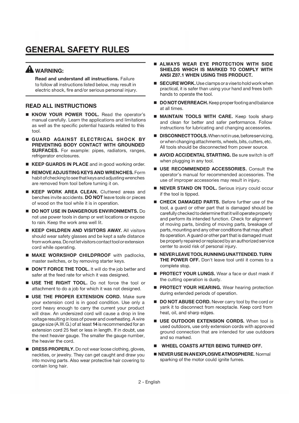
Read and understand all instructions. Failure to follow all instructions listed below, may result in electric shock, fire and/or serious personal injury.
READ ALL INSTRUCTIONS
■ KNOW YOUR POWER TOOL. Read the operator's manual carefully. Learn the applications and limitations as well as the specific potential hazards related to this tool.
■ GUARD AGAINST ELECTRICAL SHOCK BY PREVENTING BODY CONTACT WITH GROUNDED SURFACES. For example: pipes, radiators, ranges, refrigerator enclosures.
- KEEP GUARDS IN PLACE and in good working order.
- REMOVE ADJUSTING KEYS AND WRENCHES. Form habit of checking to see that keys and adjusting wrenches are removed from tool before turning it on.
- KEEP WORK AREA CLEAN. Cluttered areas and benches invite accidents. DO NOT leave tools or pieces of wood on the tool while it is in operation.
DO NOT USE IN DANGEROUS ENVIRONMENTS. Do not use power tools in damp or wet locations or expose to rain. Keep the work area well lit.
- KEEP CHILDREN AND VISITORS AWAY. All visitors should wear safety glasses and be kept a safe distance from work area. Do not let visitors contact tool or extension cord while operating.
MAKE WORKSHOP CHILDPROOF with padlocks, master switches, or by removing starter keys.
DON'T FORCE THE TOOL. It will do the job better and safer at the feed rate for which it was designed.
USE THE RIGHT TOOL. Do not force the tool or attachment to do a job for which it was not designed.
USE THE PROPER EXTENSION CORD. Make sure your extension cord is in good condition. Use only a cord heavy enough to carry the current your product will draw. An undersized cord will cause a drop in line voltage resulting in loss of power and overheating. A wire gauge size (A.W.G.) of at least 14 is recommended for an extension cord 25 feet or less in length. If in doubt, use the next heavier gauge. The smaller the gauge number, the heavier the cord.
DRESS PROPERLY. Do not wear loose clothing, gloves, neckties, or jewelry. They can get caught and draw you into moving parts. Also wear protective hair covering to contain long hair.
ALWAYS WEAR EYE PROTECTION WITH SIDE SHIELDS WHICH IS MARKED TO COMPLY WITH ANSI Z87.1 WHEN USING THIS PRODUCT.
SECUREWORK.Use clamps or a vise to hold work when practical, it is safer than using your hand and frees both hands to operate the tool.
■ DONOT OVERREACH. Keep proper footing and balance at all times.
- MAINTAIN TOOLS WITH CARE. Keep tools sharp and clean for better and safer performance. Follow instructions for lubricating and changing accessories.
- DISCONNECT TOOLS. When not in use, before servicing, or when changing attachments, wheels, bits, cutters, etc. All tools should be disconnected from power source.
AVOID ACCIDENTAL STARTING. Be sure switch is off when plugging in any tool.
USE RECOMMENDED ACCESSORIES. Consult the operator's manual for recommended accessories. The use of improper accessories may result in injury.
NEVER STAND ON TOOL. Serious injury could occur if the tool is tipped.
- CHECK DAMAGED PARTS. Before further use of the tool, a guard or other part that is damaged should be carefully checked to determine that it will operate properly and perform its intended function. Check for alignment of moving parts, binding of moving parts, breakage of parts, mounting and any other conditions that may affect its operation. A guard or other part that is damaged must be properly repaired or replaced by an authorized service center to avoid risk of personal injury.
NEVERLEAVE TOOL RUNNING UNATTENDED. TURN THE POWER OFF. Don't leave tool until it comes to a complete stop.
PROTECT YOUR LUNGS. Wear a face or dust mask if the cutting operation is dusty.
PROTECT YOUR HEARING. Wear hearing protection during extended periods of operation.
- DO NOT ABUSE CORD. Never carry tool by the cord or yank it to disconnect from receptacle. Keep cord from heat, oil, and sharp edges.
USE OUTDOOR EXTENSION CORDS. When tool is used outdoors, use only extension cords with approved ground connection that are intended for use outdoors and so marked.
WHEEL COASTS AFTER BEING TURNED OFF.
NEVERUSEINANEXPLOSIVEATMOSPHERE.Normal sparking of the motor could ignite fumes.
INSPECT TOOL CORDS PERIODICALLY. If damaged, have repaired by a qualified service technician at an authorized service facility. The conductor with insulation having an outer surface that is green with or without yellow stripes is the equipment-grounding conductor. If repair or replacement of the electric cord or plug is necessary, do not connect the equipment-grounding conductor to a live terminal. Repair or replace a damaged or worn cord immediately. Stay constantly aware of cord location and keep it well away from the rotating wheel.
INSPECT EXTENSION CORDS PERIODICALLY and replace if damaged.
- POLARIZED PLUGS. To reduce the risk of electric shock, this tool has a polarized plug (one blade is wider than the other). This plug will fit in a polarized outlet only one way. If the plug does not fit fully in the outlet, reverse the plug. If it still does not fit, contact a qualified electrician to install the proper outlet. Do not change the plug in any way.
- KEEP TOOL DRY, CLEAN, AND FREE FROM OIL AND GREASE. Always use a clean cloth when cleaning. Never use brake fluids, gasoline, petroleum-based products, or any solvents to clean tool.
STAY ALERT AND EXERCISE CONTROL. Watch what you are doing and use common sense. Do not operate tool when you are tired. Do not rush.
DO NOT USE TOOL IF SWITCH DOES NOT TURN IT ON AND OFF. Have defective switches replaced by an authorized service center.
NEVER TOUCH WHEEL or other moving parts during use.
NEVER START THE CUT-OFF MACHINE WHEN THE WHEEL IS IN CONTACT WITH THE MATERIAL.
DO NOT OPERATE A TOOL WHILE UNDER THE INFLUENCE OF DRUGS, ALCOHOL, OR ANY MEDICATION.
WHENSERVICING use only identical replacement parts. Use of any other parts may create a hazard or cause product damage.
- USE ONLY RECOMMENDED ACCESSORIES listed in this manual or addendums. Use of accessories that are not listed may cause the risk of personal injury. Instructions for safe use of accessories are included with the accessory.
DOUBLECHECKALLSETUPS.Make sure wheel is tight and not making contact with tool or workpiece before connecting to power supply.
SPECIFIC SAFETY RULES
■ FIRMLY CLAMP OR BOLT your tool to a workbench or table at approximately hip height.
USEONLYCORRECTWHEELS.Donotuse wheels with incorrect size holes.Never use wheel washers or wheel screws that are defective or incorrect.The maximum wheel capacity of your cut-off machine is 14 in.
- DONOTREMOVETHEMACHINE'SWHEELGUARDS. Never operate the machine with any guard or cover removed. Make sure all guards are operating properly before each use.
- KEEP HANDS AWAY FROM CUTTING AREA. Keep hands away from wheel. Do not reach underneath work or around or under the wheel while the wheel is rotating. Do not attempt to remove cut material while wheel is moving.
ALWAYS SUPPORT LONG MATERIAL. To minimize risk of tipping machine, always support long material.
BEFORE MAKING A CUT, BE SURE ALL ADJUSTMENTS ARE SECURE.
ALWAYS USE THE VISE CLAMP to secure the material.
NEVER cut more than one piece of material at a time. DO NOT STACK more than one piece of material on the machine base at a time.
NEVER PERFORM ANY OPERATION "FREEHAND". Always secure the material to be cut in the vise.
NEVER hand hold a piece of material. Material will become very hot while being cut.
NEVER reach behind, under, or within three inches of the wheel and its cutting path with your hands and fingers for any reason.
NEVER reach to pick up a piece of material, a piece of scrap, or anything else that is in or near the cutting path of the wheel.
AVOID AWKWARD OPERATIONS AND HAND POSITIONS where a sudden slip could cause your hand to move into the wheel. ALWAYS make sure you have good balance.
NEVER stand or have any part of your body in line with the path of the wheel.
ALWAYS release the power switch and allow the wheel to stop rotating before raising wheel guard or removing material.
DO NOT TURN THE MOTOR SWITCH ON AND OFF RAPIDLY. This could cause the wheel to loosen and could create a hazard. Should this ever occur, stand clear and allow the wheel to come to a complete stop. Disconnect your cut-off machine from the power supply and securely retighten the wheel arbor bolt after checking the wheel for damage.
NEVER leave the cut-off machine unattended while connected to a power source.
IF ANY PART OF THIS CUT-OFF MACHINE IS MISSING or should break, bend, or fail in any way, or should any electrical component fail to perform properly, shut off the power switch, remove the machine plug from the power source and have damaged, missing, or failed parts replaced before resuming operation.
MAKE SURE THE CUT-OFF WHEEL IS SECURELY MOUNTED as described in the operating instructions before connecting the tool to a power supply. Do not tighten wheel excessively, since this can cause cracks.
CHECK THE WHEEL FOR FISSURES AND CRACKS, and test for normal operation prior to use.
ONLY USE A CUT-OFF WHEEL RATED FOR 3,900 RPM OR GREATER and manufactured in compliance with ANSI B7.1. Always store wheels in a dry place with little temperature variation.
ALWAYS EASE THE ABRASIVE WHEEL AGAINST THE MATERIAL when starting to cut. A harsh impact can break the wheel.
BEFORE CUTTING press the trigger switch and allow the cut-off wheel to reach full speed.
■ MAKESURETHEWORKAREAHASAMPLELIGHTING to see the work and that no obstructions will interfere with safe operation BEFORE performing any work using your cut-off machine.
ALWAYS STAY ALERT! Do not allow familiarity (gained from frequent use of your cut-off machine) to cause a careless mistake. ALWAYS REMEMBER that a careless fraction of a second is sufficient to inflict severe injury.
USEONLYFLANGESfurnished with this cut-off machine.
DO NOT OVERTIGHTEN THE WHEEL NUT. Excessive tightening can cause the wheel to crack during operation.
FREQUENTLY clean dust from beneath the cut-off machine.
IF THE POWER SUPPLY CORD IS DAMAGED, it must be replaced only by the manufacturer or by an authorized service center to avoid risk.
■ RISK OF FIRE OR EXPLOSION. This product has parts such as snap switches, receptacles, and the like, which tend to produce arcs or sparks. Therefore, when located in a garage, the machine should be 18 in. above the floor and located in a separate room.
SAVE THESE INSTRUCTIONS. Refer to them frequently and use them to instruct other users. If you loan someone this tool, loan them these instructions also.
| The following signal words and meanings are intended to explain the levels of risk associated with this product. SYMBOL | SIGNAL | MEANING |
| A | DANGER: | Indicates a hazardous situation, which, if not avoided, will result in death or serious injury. |
| A | WARNING: | Indicates a hazardous situation, which, if not avoided, could result in death or serious injury. |
| A | CAUTION: | Indicates a hazardous situation, that, if not avoided, may result in minor or moderate injury. |
| NOTICE: | (Without Safety Alert Symbol) Indicates information considered important, but not related to a potential injury (e.g. messages relating to property damage). | |
| Some of the following symbols may be used on this tool. Please study them and learn their meaning. Proper interpretation of these symbols will allow you to operate the tool better and safer. SYMBOL NAME DESIGNATION/EXPLANATION | ||
| Safety Alert Indicates a potential personal injury hazard. | ||
| Read Operator's Manual | To reduce the risk of injury, user must read and understand operator's manual before using this product. | |
| Eye Protection | Always wear eye protection with side shields marked to comply with ANSI Z87.1. | |
| No Hands Symbol | Failure to keep your hands away from the blade will result in serious personal injury. | |
| Wet Conditions Alert Do not expose to rain or use in damp locations. | ||
| Hot Surface To reduce the risk of injury or damage, avoid contact with any hot surface. | ||
| V Volts Voltage | ||
| A Amperes Current | ||
| Hz Hertz Frequency (cycles per second) | ||
| min Minutes Time | ||
| ~ | Alternating Current Type of current | |
| no | No Load Speed Rotational speed, at no load | |
| Class II Construction Double-insulated construction | ||
| .../min | Per Minute | Revolutions, strokes, surface speed, orbits, etc., per minute |
DOUBLE INSULATION
Double insulation is a concept in safety in electric power tools, which eliminates the need for the usual three-wire grounded power cord. All exposed metal parts are isolated from the internal metal motor components with protecting insulation. Double insulated tools do not need to be grounded.

WARNING:
The double insulated system is intended to protect the user from shock resulting from a break in the tool's internal wiring. Observe all normal safety precautions to avoid electrical shock.
NOTE: Servicing of a product with double insulation requires extreme care and knowledge of the system and should be performed only by a qualified service technician. For service, we suggest you return the tool to your nearest authorized service center for repair. Always use original factory replacement parts when servicing.
ELECTRICAL CONNECTION
This tool has a precision-built electric motor. It should be connected to a power supply that is 120V, AC only (normal household current), 60 Hz. Do not operate this tool on direct current (DC). A substantial voltage drop will cause a loss of power and the motor will overheat. If the tool does not operate when plugged into an outlet, double check the power supply.
EXTENSION CORDS
When using a power tool at a considerable distance from a power source, be sure to use an extension cord that has the capacity to handle the current the product will draw. An undersized cord will cause a drop in line voltage, resulting in overheating and loss of power. Use the chart to determine
the minimum wire size required in an extension cord. Only round jacketed cords listed by Underwriter's Laboratories (UL) should be used.
When working outdoors with a product, use an extension cord that is designed for outside use. This type of cord is designated with "WA" or "W" on the cord's jacket.
Before using any extension cord, inspect it for loose or exposed wires and cut or worn insulation.
**Ampere rating (on product data plate) 0-2.0 2.1-3.4 3.5-5.0 5.1-7.0 7.1-12.0 12.1-16.0
| Cord Length | Wire Size (A.W.G.) | ||||||
| 25' | 16 | 16 | 16 | 16 | 14 | 14 | |
| 50' | 16 | 16 | 16 | 14 | 14 | 12 | |
| 100' | 16 | 16 | 14 | 12 | 10 | - | |
**Used on 12 gauge - 20 amp circuit.
NOTE: AWG = American Wire Gauge

WARNING:
Keep the extension cord clear of the working area. Position the cord so that it will not get caught on lumber, tools, or other obstructions while you are working with a power tool. Failure to do so can result in serious personal injury.

WARNING:
Check extension cords before each use. If damaged replace immediately. Never use tool with a damaged cord since touching the damaged area could cause electrical shock resulting in serious injury.
PRODUCT SPECIFICATIONS
Input. 120 V, AC Only, 60 Hz, 15 Amps
No Load Speed. 3,900 r/min. (RPM)
■ Arbor Diameter 1 in.
Wheel Diameter 14 in.
Fence Angle... right (45irc) left (45irc)
Maximum Cutting Capacities: Round Pipe 5 in. outside diameter Bar Stock 2 in.
KNOW YOUR CUT-OFF MACHINE
See Figure 1, page 16.
The safe use of this product requires an understanding of the information on the tool and in this operator's manual as well as a knowledge of the project you are attempting. Before use of this product, familiarize yourself with all operating features and safety rules.
14 in. ABRASIVE WHEEL
A 14 in. abrasive wheel is included with your cut-off machine. It will cut materials up to 5 in. thick or 8 in. wide, depending upon the thickness or width of the material and the setting at which the cut is being made.
ADJUSTABLE FENCE
The fence on your cut-off machine has been provided to support the material and provide clamping support to the vise for holding your material securely when making all cuts. It is an adjustable fence that has been provided to make your cut-off machine more versatile. It adjusts from 0irc to 45irc to the right or left for making angled cuts. The hole pattern allows it to be moved forward when making cuts in tall or thick stock, such as square stock or tube stock. The hole pattern allows it to be moved back when making cuts in stock that is thin or wide, such as angle stock.
ADJUSTABLE STOP
In the down (full cut) position, the pivot arm hits an adjustable stop on the support bracket.
ARBOR WRENCH
The arbor wrench is found on the side of the base. Use wrench when replacing cut-off wheel or when making fence angular adjustments.
CARRYING HANDLE
This handle is built into the unit to move it from one location to another. Before attempting to pick up the unit by the carrying handle always lock the power head in the down position using the transport chain.
"D" HANDLE
The handle contains the trigger switch with a padlock locking hole to prevent unauthorized use. The wheel is lowered into the material by pushing down on the handle. The wheel will return to its upright position when the handle is released.
LOWER WHEEL GUARD
The lower wheel guard provides protection from each side of the wheel. Contact with the material causes the lower guard to raise over the upper wheel guard as the wheel is lowered into the material.
MITER LOCK HANDLE
Allows the adjustable fence to be pivoted at a given angle then locked in place.
MOTOR
This machine has a strong motor with sufficient power to handle tough cutting jobs. It also has externally accessible brushes for ease of servicing.
ON/OFF SWITCH
To start the tool, squeeze the trigger. Release the trigger to stop the tool. Install a padlock through the hole in the trigger to help prevent unauthorized use.
QUICK RELEASE LEVER
A quick release lever has been provided on your cut-off machine. This feature allows you to open and close the visse clamp quickly without repetitive turning of the visse crank handle.
SPINDLE LOCK
A spindle lock has been provided for locking the spindle which keeps the wheel in your machine from rotating. Depress and hold the spindle lock while installing, changing, or removing wheel only.
TRANSPORT CHAIN
The cut-off machine can be locked in the lowered position for compact storage. The chain is only used during carrying and storage operations.
UPPER WHEEL GUARD
Protects user from abrasive wheel contact on upper portion of wheel.
VISE CLAMP
A vise clamp has been provided with your cut-off machine. It is located on the end of the vise screw and provides greater control by clamping the material to the fence. It also prevents the material from creeping toward the wheel during a cutting operation.
UNPACKING
This product has been shipped completely assembled.
- Carefully lift machine from the carton by the carrying handle and the machine base, and place it on a level work surface.
NOTE: This tool is heavy. To avoid back injury, lift with your legs, not your back, and get help when needed.

WARNING:
Do not use this product if it is not completely assembled or if any parts appear to be missing or damaged. Use of a product that is not properly and completely assembled could result in serious personal injury.
This machine has been shipped with the machine arm secured in the down position. To release the machine arm, push down on the "D" handle and unhook the transport chain.

WARNING:
The machine arm is spring loaded. Hold the handle down to prevent it from snapping up when the transport chain is unhooked. Failure to do so could result in possible serious injury.
- Lift the machine arm by the handle. Hand pressure should remain on the "D" handle to prevent sudden rise upon release of the transport chain.
Inspect the tool carefully to make sure no breakage or damage occurred during shipping. - Do not discard the packing material until you have carefully inspected and satisfactorily operated the tool.
The machine is factory set for accurate cutting. After assembling it, check for accuracy. If shipping has influenced the settings, refer to specific procedures explained in this manual.
If any parts are damaged or missing, please call 1-866-539-1710 for assistance.
PACKING LIST
Abrasive Cut-off Machine
Arbor Wrench
Operator's Manual

WARNING:
If any parts are damaged or missing, do not operate this tool until the parts are replaced. Use of this product with damaged or missing parts could result in serious personal injury.

WARNING:
Do not attempt to modify this tool or create accessories not recommended for use with this tool. Any such alteration or modification is misuse and could result in a hazardous condition leading to possible serious personal injury.

WARNING:
Do not connect to power supply until assembly is complete. Failure to comply could result in accidental starting and possible serious personal injury.

WARNING:
A 14 in. wheel is the maximum wheel capacity of the cut-off machine. Never use a wheel that is too thick to allow outer flange to engage with the flats on the spindle. Larger wheels will come in contact with the wheel guards, while thicker wheels will prevent the bolt from securing the wheel on the spindle. Either of these situations could result in a serious accident and can cause serious personal injury.
MOUNTING HOLES
See Figure 2, page 17.
The saw should be mounted to a firm supporting surface such as a workbench. Bolt holes have been provided in the saw base for this purpose. Each of the mounting holes should be bolted securely using machine bolts, lock washers, and hex nuts (not included). Bolts should be of sufficient length to accommodate the saw base, lock washers, hex nuts, and the thickness of the workbench. Tighten all bolts securely.
Carefully check the workbench after mounting to make sure that no movement can occur during use. If any tipping, sliding, or walking is noted, secure the workbench to the floor before operating.
INSTALLATION/REMOVAL OF WHEEL
See Figure 3, page 17.

WARNING:
Do not overtighten wheel bolt. Overtightening can cause the new wheel to crack, resulting in premature failure and possible serious personal injury.

WARNING:
If inner flange or inner washer has been removed, replace both before placing wheel on spacer and wheel arbor. Failure to do so could cause an accident since wheel will not tighten properly.
To Install:
Unplug the cut-off machine.
■ Inspect the wheel for defects such as cracks, chipping, and correct speed rating. If defects are found or the speed rating is not greater than 3,900 rpm, do not use. Select another wheel.
Clean debris from the wheel arbor.
Install inner flange on arbor then place the wheel on the arbor.
Clean outer flange then slide outer flange onto arbor until it is flush.
- Place recessed side of outer flange against wheel, then insert washer and wheel bolt into threaded end of wheel arbor.
Start threads and turn wheel bolt clockwise to snugly tighten. - Depress the spindle lock and rotate bolt until spindle locks, preventing shaft from rotating.
Using the arbor wrench provided, securely tighten wheel bolt.
NOTE: Wheel bolt has right hand threads. Turn wheel bolt clockwise to tighten.
To Remove:
Unplug the cut-off machine.
- Push down on "D" handle (machine arm) and remove transport chain from hook on motor housing to release machine arm.
- Raise machine arm to its full raised position. Be cautious when raising, machine arm is spring loaded.
- Rotate lower wheel guard upward, exposing wheel bolt that secures abrasive wheel to wheel arbor.
Depress the spindle lock and rotate wheel bolt until the spindle locks, preventing shaft from rotating.
Using the arbor wrench provided, loosen and remove wheel bolt.
NOTE: Wheel bolt has right hand threads. Turn wheel bolt counterclockwise to loosen.
- Remove wheel bolt, washer, outer flange, wheel, and inner flange.

WARNING:
Do not allow familiarity with tools to make you careless. Remember that a careless fraction of a second is sufficient to inflict severe injury.

WARNING:
Always wear eye protection with side shields marked to comply with ANSI Z87.1. Failure to do so could result in objects being thrown into your eyes, resulting in possible serious injury.

WARNING:
Do not use any attachments or accessories not recommended by the manufacturer of this tool. The use of attachments or accessories not recommended can result in serious personal injury.

WARNING:
Do not attempt to cut wood or masonry with this cut-off machine. Never cut magnesium or magnesium alloy with this machine. Failure to comply could result in serious personal injury.

WARNING:
Never install any wood cutting blade on this machine. The cut-off machine is properly guarded only for cutting metal with an abrasive wheel. Failure to comply could result in serious personal injury.

WARNING:
Always use the vise clamp on the cut-off machine to prevent accidents that could result in possible serious personal injury.
APPLICATIONS
You may use this tool for the purposes listed below:
Cutting all types of metals such as 2 in. x6 in. steel framing studs
Cutting hard metal iron stock such as square bar stock and angle iron
Cutting metal tube and pipe stock
POWER SUPPLY
Before operating the cut-off machine, check the power supply and make sure it meets the requirements listed on the tool's data plate. A substantial voltage drop will cause a loss of power and machine overheating.
Common causes of power loss and machine overheating are insufficient extension cord size and multiple tools operating from the same power source.
ON/OFF SWITCH
To turn the cut-off machine ON, depress the on/off switch located in the handle portion of the machine arm.
To turn it OFF, release the on/off switch.
CUTTING WITH THE CUT-OFF MACHINE
See Figures 4 - 5, page 17.
A cut-off is made by cutting across the width of the material. A straight cross cut is made with the adjustable fence set at the zero degree position. Angled cut-offs are made with the adjustable fence set at some angle other than zero.
Loosen the miter lock handle securing the fence.
Rotate the adjustable fence to the desired angle.
Retighten miter lock handle securing fence.

WARNING:
To avoid serious personal injury, always tighten vise adjustment bolt securely before making a cut. Failure to do so could result in movement of the material while making a cut.
Place the material flat on the machine base with one surface securely against the adjustable fence.
Align cutting line on the material with the edge of the abrasive wheel.
Push in the vise crank handle to set the vise clamp against the material. Turn the vise crank handle 1/2 to 1 turn clockwise to securely clamp the material to the fence.
■ Firmly secure the material to be cut using the machine's vise (adjustable fence and vise clamp).
- When cutting long pieces, support the opposite end of the material with a roller stand or with a work surface level with the machine base.

WARNING:
Never perform any cutting operation freehand (without securing material in the vise). Material will get hot during cutting operation. Keep hands off of metal being cut to avoid serious personal injury.
Before turning on machine, perform a dry run of the cutting operation just to make sure that no problems will occur when the cut is made.
Start the machine by grasping the handle and fully squeezing the on/off switch. Allow several seconds for the wheel to build up to full speed before letting it come into contact with the material to be cut.
Once it reaches full speed slowly lower the "D" handle until the cut-off wheel comes in contact with the material being cut. Continue to use steady and even pressure to obtain a uniform cut through the material. Never force the wheel into the material being cut.
- When the cut is complete, release the on/off switch and allow the wheel to stop rotating before raising the wheel out of material.

WARNING:
Do not touch the cut material until it cools or you can be burned. Failure to heed this warning could result in serious personal injury.
USING THE ADJUSTABLE FENCE
See Figure 6, page 18.
The adjustable fence is located at the rear of the cut-off machine. As mentioned previously, it is used along with the vise clamp to provide a clamp for holding the workpiece securely when making cuts. It also makes the cut-off machine more versatile.
The fence can be rotated to obtain cutting angles from 0irc to 45irc . It also can be moved back to allow greater cutting widths in thin stock, or forward to allow greater cutting depths in tall or thick stock.
ADJUSTING THE CUTTING ANGLE
See Figures 6 - 8, page 18.
Unplug the cut-off machine.
Loosen the miter lock handle by pushing down and rotating counterclockwise. If it needs to be further loosened, pull spring-loaded miter lock handle up and rotate it back to the right. Release handle and allow it to seat (lock) in its original position. Turn it to the left again until loose.
- Rotate fence until the desired angle of cut on the scale is aligned with the indicator in machine base.
- Tighten the miter lock handle by turning the miter lock lever to the right. If it needs to be tightened more, pull the springloaded miter lock handle up and rotate it to the left. Then release miter lock handle and allow it to return to its original position. Rotate to the right again. Repeat this process until miter lock handle is securely tightened.
This will secure the fence in place at desired angle. For precise cuts, check the angle of cut for the fence against the wheel with a protractor, bevel square, or other similar device.
ADJUSTING THE WIDTH OF CUT
See Figure 8, page 18.
The adjustable fence can be repositioned by removing the adjustment bolt.
Unplug the cut-off machine.
To increase the width of cut of the cut-off machine, use the arbor wrench to loosen and remove the adjustment bolt securing the adjustable fence to machine base.
- Reposition the adjustable fence with one of three threaded holes in back of the machine base.
Install adjustment bolt into machine base.
Check and adjust fence to desired cutting angle.
- Tighten the adjustment bolt. The maximum width capacity is approximately 8-1/4 in. at 90irc and 5 in. at 45irc .
Return arbor wrench to its storage area in base.
The quick lock-release lever engages the vise clamp to be used along with the fence to provide a vise for securing the workpiece to be cut. It also allows you to open and close the vise quickly without repetitive turning of the vise crank handle.
To loosen:
Unplug the cut-off machine.
Release tension on the vise clamp by rotating the vise crank handle 1/2 to 1 turn counterclockwise.
Lift up the quick lock-release lever as shown in figure 9 and pull back on vise crank handle to slide open the vise.
To tighten:
Unplug the cut-off machine.
- Push the vise crank handle forward to slide the vise clamp against the workpiece.
- Rotate the quick lock-release lever forward and push down as shown in figure 10 to engage its threads with the vise screw.
- Rotate the vise crank handle clockwise to tighten the vise clamp against the workpiece.

WARNING:
Before performing any adjustment, make sure the tool is unplugged from the power supply. Failure to heed this warning could result in serious personal injury.
DEPTH STOP
See Figure 11, page 19.
The depth stop limits the wheel's downward travel. It allows the wheel to go below the machine base enough to maintain full cutting capacities.
The adjustable depth stop is a bolt threaded into the pivot bracket at the rear. To adjust the depth stop use the arbor wrench supplied to raise or lower the depth stop bolt.
The depth stop is factory set to provide maximum cutting capacity for the 14 in. abrasive wheel provided with the cut-off machine.
When the diameter of the wheel has been reduced due to wear, it may be necessary to adjust the depth stop to provide maximum cutting capacity. When a new abrasive wheel is installed, it is necessary to check the clearance of the wheel to the machine base support.
Unplug the cut-off machine.
- Slide the arbor wrench over the depth stop bolt and onto the lock nut.
Loosen the lock nut.
- Move the arbor wrench up and onto the head of the depth stop bolt.
Hold the lock nut and adjust the depth stop bolt.
NOTE: The depth stop is lowered by turning the depth stop bolt clockwise and raised by turning the bolt counterclockwise.
Once the depth stop bolt is in the desired position, tighten the lock nut to secure it in place.
- By pressing down on the machine arm, lower the wheel and check clearance and maximum cutting distance (distance from adjustable stationary vise where wheel enters) to front of machine base slot.
Adjust if necessary.
NOTICE:
Do not start the cut-off machine without checking for interference between the wheel and the machine base support. Damage may result to the wheel if it strikes the machine base support during operation of the machine.

WARNING:
When servicing, use only identical replacement parts. Use of any other part can create a hazard or cause product damage.

WARNING:
Always wear eye protection with side shields marked to comply with ANSI Z87.1 during product operation. If operation is dusty, also wear a dust mask.
GENERAL
Avoid using solvents when cleaning plastic parts. Most plastics are susceptible to damage from various types of commercial solvents and may be damaged by their use. Use a clean cloth to remove dirt, carbon dust, etc.

WARNING:
Do not at any time let brake fluids, gasoline, petroleum-based products, penetrating oils, etc., come in contact with plastic parts. Chemicals can damage, weaken or destroy plastic which could result in serious personal injury.
LUBRICATION
All of the bearings in this tool are lubricated with a sufficient amount of high grade lubricant for the life of the unit under normal operating conditions. Therefore, no further lubrication is required.
BRUSH REPLACEMENT
See Figure 12, page 19.
The cut-off machine has externally accessible brush assemblies that should be periodically checked for wear.
Proceed as follows when replacement is required:
Unplug the cut-off machine.
- Remove brush cap with a screwdriver. Brush assembly is spring loaded and will pop out when you remove brush cap.
Remove brush assembly.
Check for wear. Replace both brushes when either has less than 1/4 in. length of carbon remaining. Do not replace one side without replacing the other.
Reassemble using new brush assemblies. Make sure curvature of brush matches curvature of motor and that brush moves freely in brush tube.
Make sure brush cap is oriented correctly (straight) and replace.
- Tighten brush cap securely. Do not overtighten.
NOTE: ILLUSTRATIONS START ON PAGE 16 AFTER FRENCH AND SPANISH LANGUAGE SECTIONS.
| PROBLEM POSSIBLE | CAUSE SOLUTION | |
| Machine does not start Power | cord not plugged in. | Plug in cord. |
| Power cord is damaged. | Have the cord replaced at your nearest authorized service center. | |
| Circuit breaker is tripped. | Reset circuit breaker. | |
| Circuit fuse is blown. | Replace circuit fuse. | |
| Switch is damaged or burned out. | Have the switch replaced at your nearest authorized service center and request a voltage check from the power company. | |
| Motor does not reach full speed or power | Voltage from power source is low. | Request a voltage check from the power company. |
| Circuit is overloaded. | Test on a different circuit or without anything else on circuit. | |
| Motor burned out. | Have tool serviced and request a voltage check from the power company. | |
| Fuses or circuit breakers are wrong size. | Have an electrician replace with a 15 amp fuse or circuit breaker. | |
| Extension cord is too long. | Use a shorter extension cord. | |
| Switch is defective. | Have the switch replaced at your nearest authorized service center. | |
| Motor stalls, blows fuses, or trips circuit breakers | Switch is defective. | Have the switch replaced at your nearest authorized service center. |
| Voltage from source is low. | Request a voltage check from the power company. | |
| Fuses or circuit breakers are wrong size or defective. | Have an electrician replace with a 15 amp fuse or circuit breaker. | |
| Motor overheats Motor is overoaded. | Oaded. | Request a voltage check from the power company. |
| Wheel is being fed into work too fast. | Feed wheel into work slower. | |
| Machine is noisy when running | Motor needs attention. Have the motor checked | checked at your nearest authorized service center |
| Wheel hits table Wheel not properly installed. | Depth stop setting incorrect. | See Installation/Removal of Wheel section. Adjust the depth stop. See Depth Stop section. |
| Wheel does not cut through material | Depth stop setting incorrect. | Adjust the depth stop. See Depth Stop section. |
| Wheel worn too much. | Replace with a new 14 in. abrasive cut off wheel. | |
| Incorrect cutting operation. | See Cutting with the Cut-Off Machine. | |
| Machine vibrates or shakes excessively | Wheel is out-of-round. | Replace wheel. |
| Wheel is chipped. | Replace wheel. | |
| Wheel is loose. | Tighten wheel bolt on arbor. | |
| Machine is not secure. | Check and tighten all hardware. | |
| Work surface is uneven. | Relocate and secure on a flat surface. |
If problem persists after trying the above solutions, contact customer service or an authorized service center for assistance.
RIDGID® HAND HELD AND STATIONARY POWER TOOL 3 YEAR LIMITED SERVICE WARRANTY
Proof of purchase must be presented when requesting warranty service.
Limited to RIDGID® hand held and stationary power tools purchased 2/1/04 and after. This product is manufactured by One World Technologies, Inc. The trademark is licensed from RIDGID®, Inc. All warranty communications should be directed to One World Technologies, Inc., attn: RIDGID® Hand Held and Stationary Power Tool Technical Service at (toll free) 1-866-539-1710.
90-DAY SATISFACTION GUARANTEE POLICY
During the first 90 days after the date of purchase, if you are dissatisfied with the performance of this RIDGID® Hand Held and Stationary Power Tool for any reason you may return the tool to the dealer from which it was purchased for a full refund or exchange. To receive a replacement tool you must present proof of purchase and return all original equipment packaged with the original product. The replacement tool will be covered by the limited warranty for the balance of the 3 YEAR service warranty period.
WHAT IS COVERED UNDER THE 3 YEAR LIMITED SERVICE WARRANTY
This warranty on RIDGID® Hand Held and Stationary Power Tools covers all defects in workmanship or materials and normal wear items such as brushes, chucks, motors, switches, cords, gears and even cordless batteries in this RIDGID® tool for three years following the purchase date of the tool. Warranties for other RIDGID® products may vary.
HOW TO OBTAIN SERVICE
To obtain service for this RIDGID® tool you must return it; freight prepaid, or take it in to an authorized service center for RIDGID® branded hand held and stationary power tools. You may obtain the location of the authorized service center nearest you by calling (toll free) 1-866-539-1710 or by logging on to the RIDGID® website at www.ridgid.com. When requesting warranty service, you must present the original dated sales receipt. The authorized service center will repair any faulty workmanship, and either repair or replace any part covered under the warranty, at our option, at no charge to you.
WHAT IS NOT COVERED
This warranty applies only to the original purchaser at retail and may not be transferred. This warranty only covers defects arising under normal usage and does not cover any malfunction, failure or defect resulting from misuse, abuse, neglect, alteration, modification or repair by other than an authorized service center for RIDGID® branded hand held and stationary power tools. Consumable accessories provided with the tool such as, but not limited to, blades, bits and sand paper are not covered.
RIDGID, INC. AND ONE WORLD TECHNOLOGIES, INC. MAKE NO WARRANTYES, REPRESENTATIONS OR PROMISES AS TO THE QUALITY OR PERFORMANCE OF ITS POWER TOOLS OTHER THAN THOSE SPECIFICALLY STATED IN THIS WARRANTY.
ADDITIONAL LIMITATIONS
To the extent permitted by applicable law, all implied warranties, including warranties of MERCHANTABILITY or FITNESS FOR A PARTICULAR PURPOSE, are disclaimed. Any implied warranties, including warranties of merchantability or fitness for a particular purpose, that cannot be disclaimed under state law are limited to three years from the date of purchase. One World Technologies, Inc. and RIDGID, Inc. are not responsible for direct, indirect, incidental or consequential damages. Some states do not allow limitations on how long an implied warranty lasts and/or do not allow the exclusion or limitation of incidental or consequential damages, so the above limitations may not apply to you. This warranty gives you specific legal rights, and you may also have other rights which vary from state to state.
One World Technologies, Inc.
P.O.Box 1427
Anderson, SC 29622

AVERTISSEMENT :
REEMPLACEMENT DES BALAIS
Voir la figure 12, page 19.
RÉPARATIONS SOUS GARANTIE
One World Technologies, Inc.
P.O.Box 1427
Anderson, SC 29622

ADVERTENCIA :
0-2,0 2,1-3,4 3,5-5,0 5,1-7,0 7,1-12,0 12,1-16,0
Longitud del
cordon
Calibre conductores
(A.W.G.)
| 25' | 16 | 16 | 16 | 16 | 16 | 14 | 14 |
| 50' | 16 | 16 | 16 | 14 | 14 | 14 | 12 |
| 100' | 16 | 16 | 14 | 12 | 10 | - |
**Se usa en los circuitos de calibre 12, de 20 amperes.
NOTA: AWG = American Wire Gauge

ADVERTENCIA :
One World Technologies, Inc.
P.O.Box 1427
Anderson, SC 29622
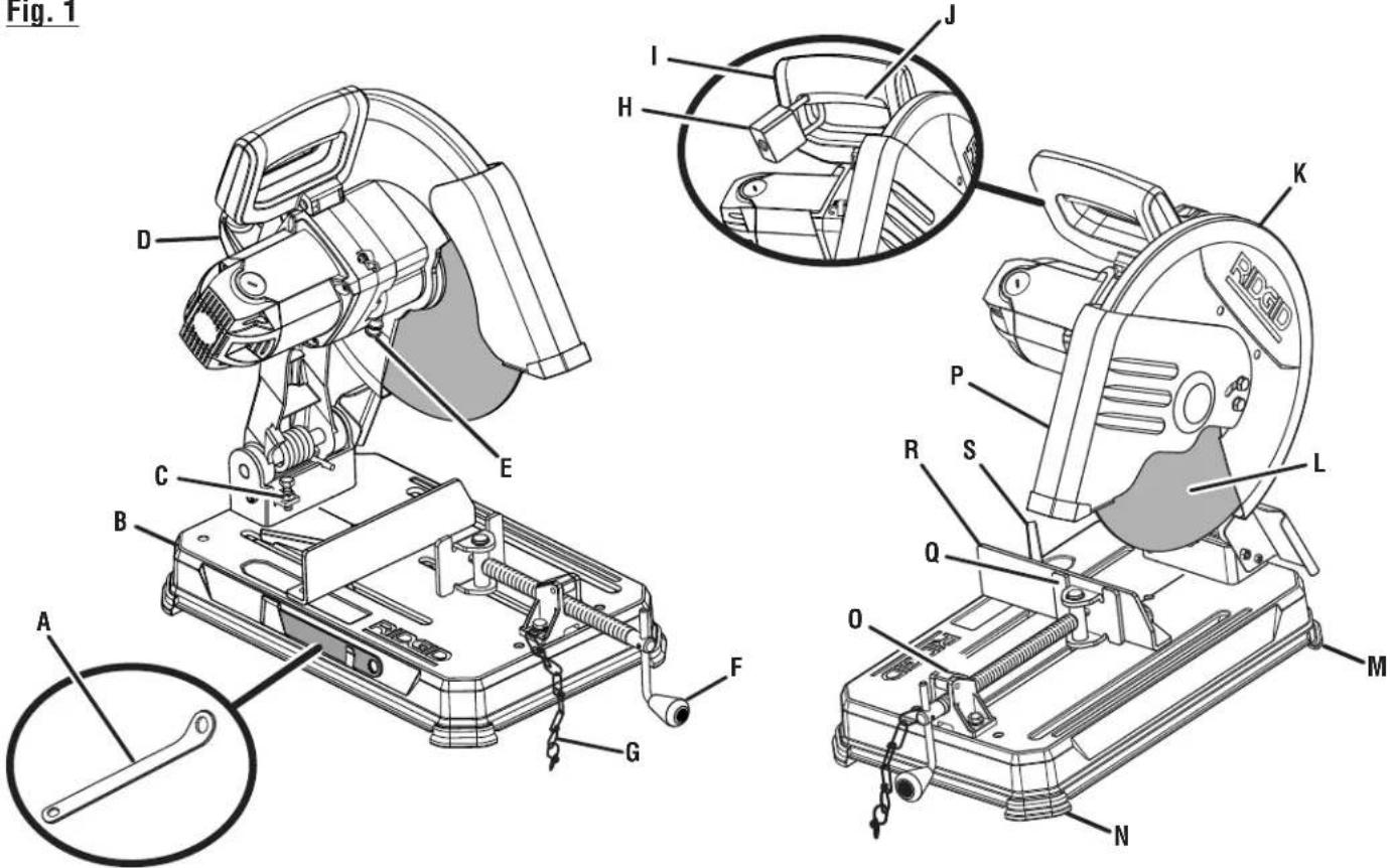
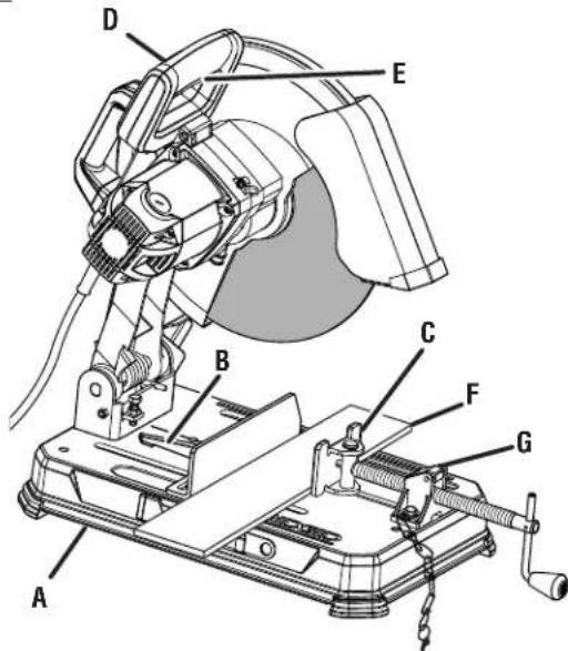
Fig.1
A-Arbor wrench (cle d'axe,llave del arbol)
B - Machine base (base de la machine, base de laquina)
C-Adjustable stop (butée réglable, tope ajustable)
D-Carrying handle (poignée de transport, mango de acarreo)
E - Spindle lock (blocage de la broche, bloqueo del husillo)
F-Vise crank handle (poignée de l'etu, manivela de la prensa)
G-Transport chain (chaine de transport, cadena de traslado)
H - Padlock (not included) [cadenas (non inclus), candido (no inclida)]
I - "D" handle (poignée en « D », mango en "D")
J - On/off switch (commutateur marche/arret, interruptor de marcha/ apagado)
K - Upper wheel guard (garde de disque supérieure, proteccion superior del disco)
L - Abrasive wheel (disque abrasif, disco abrasivo)
M-Metal foot (pied en metal, pie de metal)
N - Rubber feet (3) [pieds en caoutchouc (3), pies de goma (3)
O - Quick release lever (levier à rapide, palanca de bloqueo rápido)
P- Lower wheel guard (garde de disque inférieure, proteccion inferior del disco)
Q-Vise clamp (etau, prensa)
R - Adjustable fence (guide régliable, guía ajustable)
S - Miter lock handle (poignée de verrouillage d'angle, manija de bloqueo del ángulo de inglete)
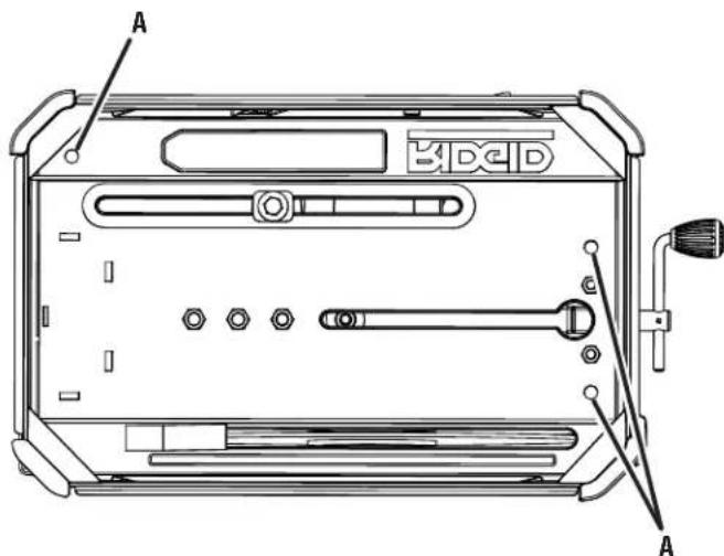
Fig. 2
BOTTOM VIEW SHOWN
(DESSOUS VUE MONTRÉ, DEBAJO DE VISTA MOSTRADO)
A - Mounting holes (trous de montage, agujeros de montaje)
Fig. 3
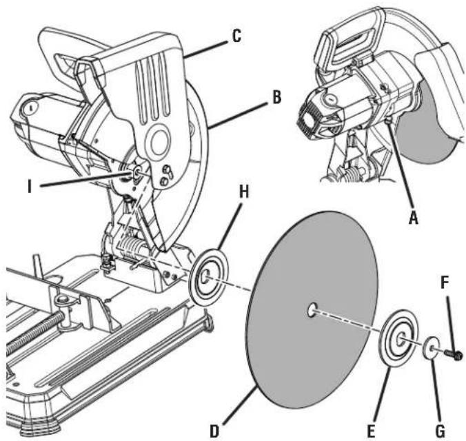
A - Spindle lock (blocage de la broche, bloqueo del husillo)
B - Upper wheel guard (garde de disque supérieure, proteccion superior del disco)
C - Lower wheel guard (garde de disque inférieure, proteccion inferior del disco)
D - Abrasive wheel (disque abrasif, disco abrasivo)
E - Outer flange (flasque extérieur, brida exterior)
F-Wheel bolt (boulon de disque,perno del disco)
G-Washer (rondelle, arandela)
H - Inner flange (flasque interieur, brida interior)
I - Wheel arbor (axe de disque, árbol del disco)
Fig. 4
A - Machine base (base de la machine, base de laquina)
B - Miter lock handle (poignée de verrouillage d'angle, manija de bloqueo del ángulo de inglete
C-Vise clamp (etau, prensa)
D-"D" handle (poignee en D , mango en "D")
E - On/off switch (commutateur marche/arrêt, interruptor de encendido)
F - Material to be cut (materiau à couper, material por cortar)
G - Quick release lever (levier à déverrouillage rapide, palanca de afloje de bloqueo rápido)
Fig. 5
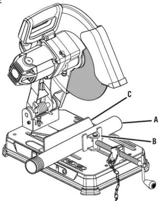
A - Material to be cut (matériau à couper, material por cortar)
B-Vise clamp (etau, prensa)
C-Adjustable fence (guide régliable, guía ajustable)
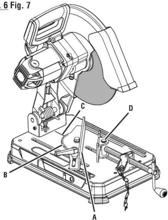
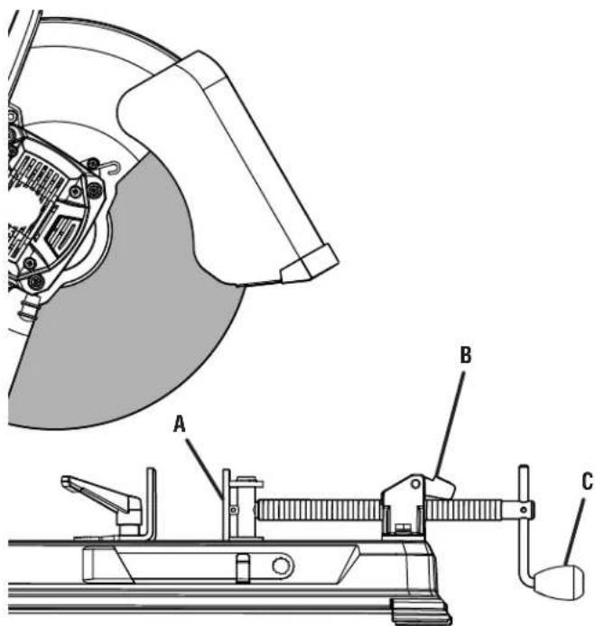
Fig.6 Fig.7
A - Adjustable fence (guide régliable, guía ajustable)
B-Fence scale (echelle du guide, escala de la guia)
C - Scale indicator (indicateur d'échelle, indicator de escalal)
D-Vise clamp (etau, prensa)
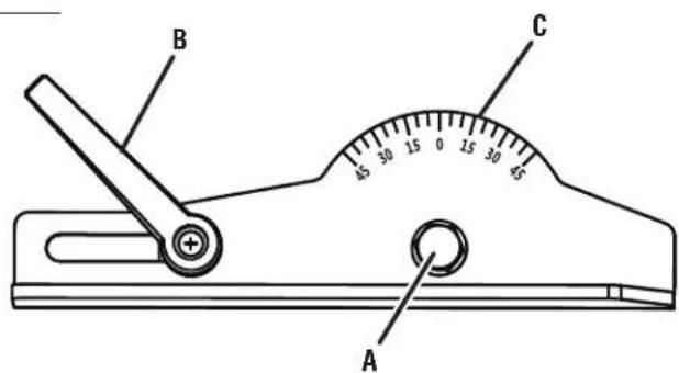
A - Adjustment bolt (boulon de réglage, perno de ajuste)
B - Miter lock handle (poignée de verrouillage d'angle, manija de bloqueo del ángulo de inglete)
C - Angle guide (guide d'angle, guia de ángulos)
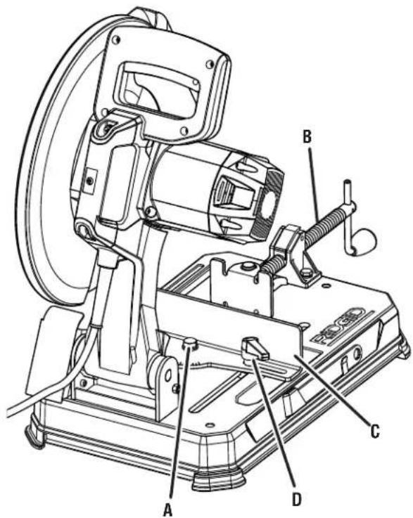
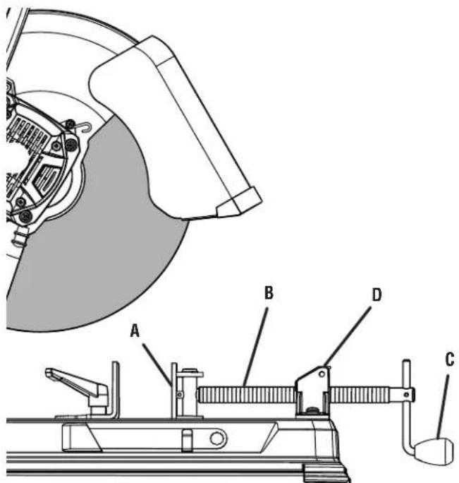
Fig. 8
A - Adjustment bolt (boulon de réglage, perno de ajuste)
B - Screw shaft (vis sans fin, enrosque tornillo)
C - Adjustable fence (guide régable, guía ajustable)
D - Miter lock handle (poignée de verrouillage d'angle, manija de bloqueo del angulo de inglete)
Fig. 9
A-Vise clamp (etau, prensa)
B - Quick lock-release lever with threads not engaged (levier de déverrouillage rapide avec filtage désengagé, palanca de aseguimiento y desenganche rápido con la roscá desenganchada)
C-Vise crank handle (poignée de l'étau, manivela de la prensa)
Fig. 10
A-Vise clamp (etau, prensa)
B-Vise screw (vis del etau, tornillo de la prensa)
C - Vise crank handle (poignée de l'étau, manivela de la prensa)
D - Quick lock-release lever with threads engaged (levier de déverrouillage rapide avec filtage engage, palanca de aseguramento y desenganche rápido con la rosca enganchada)
Customer Service Information:
For parts or service, do not return this product to the store. Contact your nearest RIDGID® authorized service center. Be sure to provide all relevant information when you call or visit. For the location of the authorized service center nearest you, please call 1-866-539-1710 or visit us online at www.RIDGID.com.
MODEL NO. SERIAL NO.
RIDGID is a registered trademark of RIDGID, Inc., used under license.
995000166
7-11-18 (REV:02)


- WARNING:
- TABLE DES MATIÈRES
- READ ALL INSTRUCTIONS
- SPECIFIC SAFETY RULES
- DOUBLE INSULATION
- ELECTRICAL CONNECTION
- EXTENSION CORDS
- PRODUCT SPECIFICATIONS
- KNOW YOUR CUT-OFF MACHINE
- See Figure 1, page 16.
- in. ABRASIVE WHEEL
- ADJUSTABLE FENCE
- ADJUSTABLE STOP
- ARBOR WRENCH
- CARRYING HANDLE
- "D" HANDLE
- LOWER WHEEL GUARD
- MITER LOCK HANDLE
- MOTOR
- ON/OFF SWITCH
- QUICK RELEASE LEVER
- SPINDLE LOCK
- TRANSPORT CHAIN
- UPPER WHEEL GUARD
- VISE CLAMP
- UNPACKING
- PACKING LIST
- MOUNTING HOLES
- INSTALLATION/REMOVAL OF WHEEL
- To Install:
- To Remove:
- APPLICATIONS
- POWER SUPPLY
- CUTTING WITH THE CUT-OFF MACHINE
- USING THE ADJUSTABLE FENCE
- See Figure 6, page 18.
- ADJUSTING THE CUTTING ANGLE
- ADJUSTING THE WIDTH OF CUT
- To loosen:
- To tighten:
- DEPTH STOP
- NOTICE:
- GENERAL
- LUBRICATION
- BRUSH REPLACEMENT
- Proceed as follows when replacement is required:
- NOTE: ILLUSTRATIONS START ON PAGE 16 AFTER FRENCH AND SPANISH LANGUAGE SECTIONS.
- RIDGID® HAND HELD AND STATIONARY POWER TOOL 3 YEAR LIMITED SERVICE WARRANTY
- 90-DAY SATISFACTION GUARANTEE POLICY
- WHAT IS COVERED UNDER THE 3 YEAR LIMITED SERVICE WARRANTY
- HOW TO OBTAIN SERVICE
- WHAT IS NOT COVERED
- ADDITIONAL LIMITATIONS
- AVERTISSEMENT :
- REEMPLACEMENT DES BALAIS
- RÉPARATIONS SOUS GARANTIE
- ADVERTENCIA :
- Longitud del
- cordon
- Calibre conductores
- (A.W.G.)
- Customer Service Information:
Brand : RIDGID
Model : R41422
Category : Saw