
258XL - Saw RIDGID - Free user manual and instructions
Find the device manual for free 258XL RIDGID in PDF.

| Product Type | Pipe Cutter |
| Brand | RIDGID |
| Model | 258XL |
| Cutting Capacity (diameter) | 8 to 12 inches (steel pipes) |
| Dimensions (H x W x D) | 27 x 13 x 24 inches |
| Weight (without drive system) | 130 lb (59 kg) |
| Weight (with drive system 700) | 161 lb (73 kg) |
| Power Supply | RIDGID 700 Drive System (110 V or 220 V) |
| Drive Motor | Industrial electric motor, reversing switch |
| Feed System | 10-ton hydraulic cylinder with two-speed pedal |
| Included Cutting Wheel | Universal wheel E258 (for schedule 40-80 pipes) |
| Included Accessories | Hydraulic pedal with hose, drive adapter No. 774, 2 ball tube supports No. 258PS |
| Options | Wheel for thin-wall pipes (schedules 10-20), transport cart, chamfering roller |
| Safety | Momentary contact switch (immediate stop), wheel guard, anti-rotation support bar |
| Maintenance | Regular cleaning of rollers and tube supports, checking hydraulic oil level, replacing worn wheel |
| Warranty | RIDGID lifetime warranty (parts and labor) |
| Transport | Handling handles (high rear and low front), optional cart |
Frequently Asked Questions - 258XL RIDGID
User questions about 258XL RIDGID
0 question about this device. Answer the ones you know or ask your own.
Ask a new question about this device
Download the instructions for your Saw in PDF format for free! Find your manual 258XL - RIDGID and take your electronic device back in hand. On this page are published all the documents necessary for the use of your device. 258XL by RIDGID.
USER MANUAL 258XL RIDGID
Read this Operator's Manual carefully before using this tool. Failure to understand and follow the contents of this manual may result in electrical shock, fire and/or serious personal injury.
Table of Contents
General Safety Information
Work Area Safety 2
Electrical Safety 2
Personal Safety 2
Tool Use and Care 3
Service 3
Specific Safety Information
Switch Safety 3
Cutter Safety 3
Description, Specifications and Accessories
Description 4
Specifications 4
Standard Equipment 4
Accessories 4
Assembly Instructions
Pipe Cutter Inspection
Pipe Cutter and Work Area Set-Up
Using Pipe Supports 7
Operating Instructions for Cutting Pipe
Cutting Thin Wall Pipe 8
Special Procedures
Adjusting Pivot Arm for Correct Pipe Size (258 Only) 9
Changing the Cutter Wheel 9
Transporting 10
Transporting Using the Transport Cart 10
Maintenance Instructions
Machine Storage.
Service and Repair
Trouble Shooting
Lifetime Warranty
Back Cover
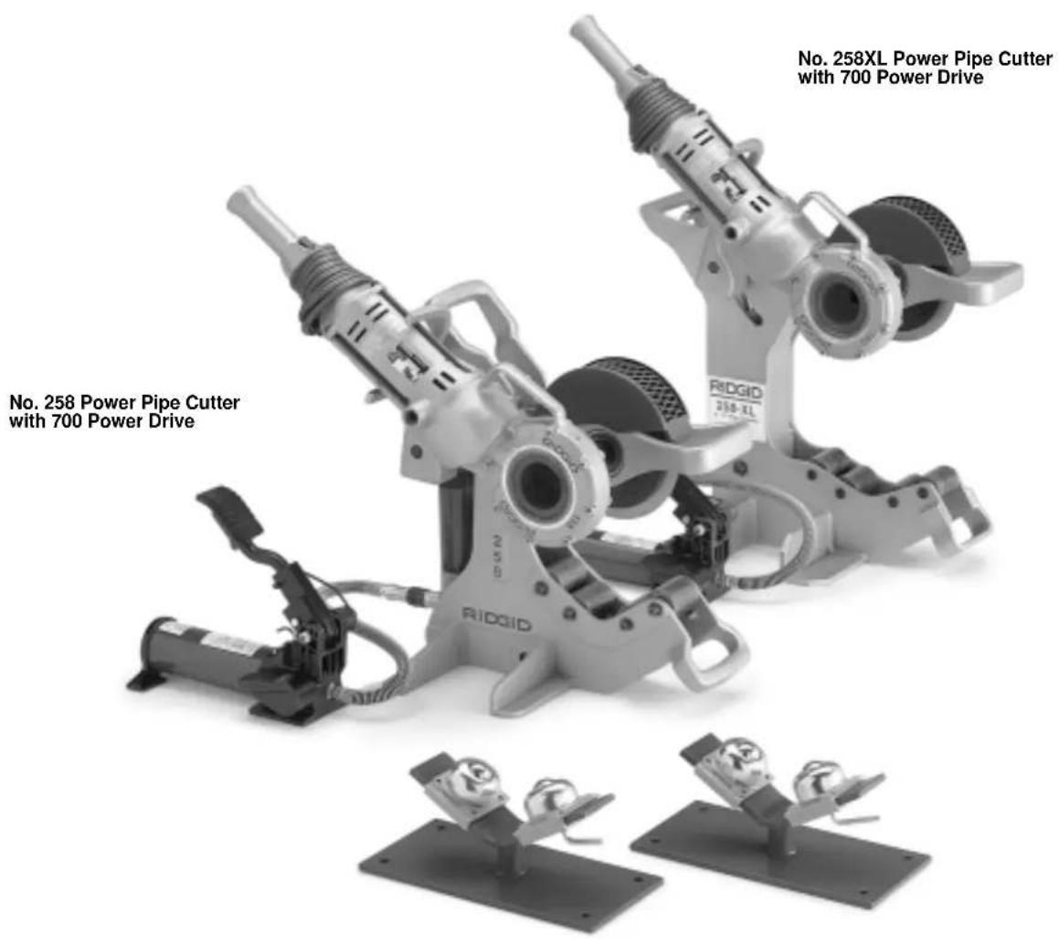
258/258XL Power Pipe Cutter
General Safety Information
WARNING! Read and understand all instructions. Failure to follow all instructions listed below may result in electric shock, fire, and/or serious personal injury.
SAVE THESE INSTRUCTIONS!
Work Area Safety
- Keep your work area clean and well lit. Cluttered benches and dark areas invite accidents.
- Do not operate power tools in explosive atmospheres, such as in the presence of flammable liquids, gases, or dust. Power tools create sparks which may ignite the dust or fumes.
- Keep by-standing, children, and visitors away while operating a power tool. Distractions can cause you to lose control.
Electrical Safety
- Grounded tools must be plugged into an outlet, properly installed and grounded in accordance with all codes and ordinances. Never remove the grounding prong or modify the plug in any way. Do not use any adapter plugs. Check with a qualified electrician if you are in doubt as to whether the outlet is properly grounded. If the tools should electrically malfunction or break down, grounding provides a low resistance path to carry electricity away from the user.

- Avoid body contact with grounded surfaces such as pipes, radiators, ranges and refrigerators. There is an increased risk of electrical shock if your body is grounded.
- Don't expose power tools to rain or wet conditions. Water entering a power tool will increase the risk of electrical shock.
- Do not abuse cord. Never use the cord to carry the tools or pull the plug from an outlet. Keep cord away from heat, oil, sharp edges or moving parts. Replace damaged cords immediately. Damaged cords increase the risk of electrical shock.
- When operating a power tool outside, use an out
door extension cord marked "W-A" or "W". These cords are rated for outdoor use and reduce the risk of electrical shock.
- Use only three-wire extension cords which have three-prong grounding plugs and three-pole receptacles which accept the machine plug. Use of other extension cords will not ground the tool and increase the risk of electrical shock.
- Use proper extension cords. (See chart.) Insufficient conductor size will cause excessive voltage drop, loss of power and overheating.
| Minimum Wire Gauge for Extension Cord | ||
| NameplateAmps TotalLength (in feet) | ||
| 0-25 26-50 51-100 | ||
| 0-6 18 AWG 16 AWG 16 AWG | ||
| 6-10 18 AWG 16 AWG 14 AWG | ||
| 10-12 16 AWG 16 AWG 14 AWG | ||
| 12-16 14 AWG 12 AWG | NOT RECOMMENDED | |
- Keep all electric connections dry and off the ground. Do not touch plugs or tool with wet hands. Reduces the risk of electrical shock.
Personal Safety
- Stay alert, watch what you are doing and use common sense when operating a power tool. Do not use tool while tired or under the influence of drugs, alcohol, or medications. A moment of inattention while operating power tools may result in serious personal injury.
- Dress properly. Do not wear loose clothing or jewelry. Contain long hair. Keep your hair, clothing, and gloves away from moving parts. Loose clothes, jewelry, or long hair can be caught in moving parts.
- Avoid accidental starting. Be sure switch is OFF before plugging in. Carrying tools with your finger on the switch or plugging tools in that have the switch ON invites accidents.
- Remove adjusting keys or switches before turning the tool ON. A wrench or a key that is left attached to a rotating part of the tool may result in personal injury.
- Do not over-reach. Keep proper footing and balance at all times. Proper footing and balance enables better control of the tool in unexpected situations.
- Use safety equipment. Always wear eye protection. Dust mask, non-skid safety shoes, hard hat, or hearing protection must be used for appropriate conditions.
Tool Use and Care
- Do not force tool. Use the correct tool for your application. The correct tool will do the job better and safer at the rate for which it is designed.
- Do not use tool if switch does not turn it ON or OFF. Any tool that cannot be controlled with the switch is dangerous and must be repaired.
- Disconnect the plug from the power source before making any adjustments, changing accessories, or storing the tool. Such preventive safety measures reduce the risk of starting the tool accidentally.
- Store idle tools out of the reach of children and other untrained persons. Tools are dangerous in the hands of untrained users.
- Maintain tools with care. Keep cutting tools sharp and clean. Properly maintained tools with sharp cutting edges are less likely to bind and are easier to control.
- Check for misalignment or binding of moving parts, breakage of parts, and any other condition that may affect the tools operation. If damaged, have the tool serviced before using. Many accidents are caused by poorly maintained tools.
- Inspect tool and extension cords periodically and replace if damaged. Damaged cords increase the risk of electrical shock.
- Keep handles dry and clean; free from oil and grease. Allows for better control of the tool.
Service
- Tool service must be performed only by qualified repair personnel. Service or maintenance performed by unqualified repair personnel could result in injury.
- When servicing a tool, use only identical replacement parts. Follow instructions in the Maintenance Section of this manual. Use of unauthorized parts or failure to follow maintenance instructions may create a risk of electrical shock or injury.
SAVE THESE INSTRUCTIONS!
Specific Safety Information
WARNING
Read this operator's manual carefully before using the 258/258XL Pipe Cutters. Failure to understand and follow the contents of this manual may result in electrical shock, fire and/or serious personal injury.
Call the Ridge Tool Company, Technical Service Department at (800) 519-3456 if you have any questions.
WARNING Switch Safety
The momentary contact switch incorporated in the power drive is for your safety. It lets you shut off the motor by removing your finger. If clothing should become caught in the pipe or cutter, it will continue to wind up, pulling you into the machine. Because the power drive has high torque, the clothing itself can bind around your arm or other body parts with enough force to crush or break bones.
Cutter Safety
- Cutter is made to cut 21/2 through 8'' or 8'' through 12'' . Follow instructions in operator's manual on proper use. Other uses may increase risk of injury.
- Keep fingers and hands away from cutter blade. Reduces risk of being cut.
- Keep guards in place. Removal of guards increases the risk of injury.
- Set-up cutter and 258 pipe supports on a flat, level surface. Be sure the cutter is stable and will not tip over. Do not use on a bench or any elevated surface. Improper set-up increases the risk of injury.
- Do not use if momentary contact switch for the 700 Power Drive is broken. The purpose of the switch is to prevent injuries.
- Secure the 700 Power Drive properly to the cutter. Carefully follow set-up instructions. Place foot pump behind cutter and near the power drive. Position the power cord clear of the blade. Improper set-up increases the risk of injury.
- Keep all personnel clear of rotating pipe. Use barricades if necessary. Prevents entanglement in the pipe.
- Do not use with dull, bent or damaged cutter wheels. Less likely to bind and lose control.
- Do not reach across cutter or rotating pipe. May become entangled in the tool causing serious injury.
-
Keep hands and feet clear of the pipe in the event it falls after being cut. High pressure exerted by the cutter may cause the cut section to fly with considerable force. May result in serious injury.
-
Cutter is designed for use with the RIDGID 700 Power Drive. Use of other power drives may increase the risk of injury.
- Wear leather gloves when handling pipe. Burrs can penetrate cloth gloves.
SAVE THESE INSTRUCTIONS!
Description, Specifications and Standard Equipment
Description
The RIDGID 258 and 258XL Power Pipe Cutters are designed to squarely cut 21 / 2 to 8 or 8 - 12 steel pipe. The cutting action is powered by the RIDGID 700 Power Drive in conjunction with a large diameter cutter wheel. The cutter wheel is advanced to the pipe via a pivot arm. The pivot arm advances the cutter wheel by utilizing a 10-ton hydraulic cylinder and foot pump.
The RIDGID 700 Portable Power Drive is an electromotor-driven heavy-duty power drive which provides power for threading pipe, conduit and rod (bolt stock). In this case, the 700 Portable Power Drive is used as the power source to rotate the cutting blade.
Specifications
Description 258 258XL
Pipe Cutting Capacity....21/2" - 8" 8" - 12"
Height (A) 22" 27"
Width (B) 11" 13"
Depth (C) 19" 24"
Weight
(without 700 PD). .95 lbs. 130 lbs. (with 700 PD) .126 lbs. 161 lbs
Standard Equipment
258 or 258XL Cutter Frame
- Two Speed Foot Pump with Hose and Coupling
- 774 Square Drive Adapter for 700 PD
258PS Ball Transfer Head Pipe Supports (2)
E258 General Purpose Cutting Wheel (Schedule 40 - 80 Capacity)
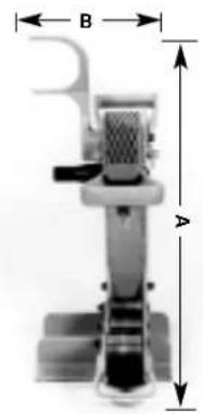

Figure 1
Figure 1A
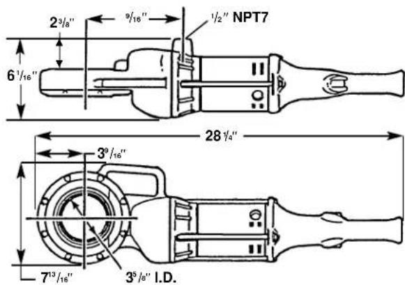
Figure 2 - No. 700 Power Drive Dimensions
Accessories
- 700 Power Drive (110 or 220 Volt)
258PS Ball Transfer Head Pipe Supports (2) - Transport Cart for 258 and 258XL
- Cutter Wheel for Thin Wall Pipe (Schedule 10 - 20 capacity)
Pipe Roller for Beveling
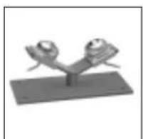
Ball Transfer Head
Cutter Wheel Transport Cart
Assembly Instructions
WARNING

To prevent serious injury, proper assembly of the Pipe Cutter is required. The following procedures should be followed:
- Connecting the hydraulic foot pump to the cutter.
a. Insert the male end of the quick-disconnect coupling into the female end located on the hydraulic cylinder (Figure 3).
b. The foot pump relief valve must be depressed to release any line pressure and allow insertion of the quick connector.

Figure 3 - Connecting Hydraulic Foot Pump to Cutter
WARNING Failure to secure the power drive with the reaction arm will result in the rotation of the power drive.
- Connecting the 700 Power Drive to the cutter.
a. Push 774 Square Drive Adapter, spline end first, squarely into power drive face gear until spring loaded adapter pawls catch securely (Figure 4).
b. Place power drive with adapter on the cutter. Power drive and adapter connect to the square drive on the cutter. Be sure power drive rests inside the reaction arm at the rear of the cutter (Figure 5).
c. Hand tighten the two set screws on the 774 square drive adapter to the square drive with 5 / 16'' allen wrench. (Provided with adapter.)
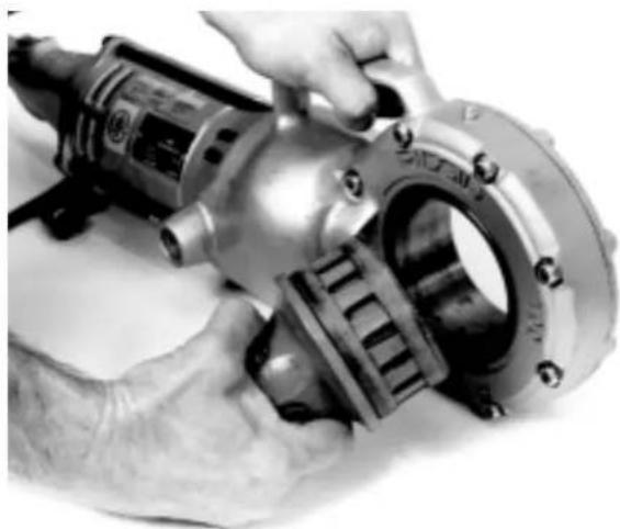
Figure 4 - Installing 774 Drive Adapter

Figure 5 - Position Power Drive Inside Reaction Arm
Pipe Cutter Inspection

WARNING
To prevent serious injury, inspect your Pipe Cutters and Power Drive. The following inspection procedures should be performed on a daily basis:
- Make sure Power Drive is unplugged.
- Inspect the cutter wheel to insure it is not dull, bent or damaged. Refer to the Special Procedures if it needs to be replaced.
- Check that the cutter frame rollers are free to rotate under the pipe. Clean debris, pipe scale and dirt from rollers.
- Insure pipe support ball transfer heads are free to move and are clean of dirt, pipe scale and debris.
- Insure the three screws and lock washers are tight in the cutter wheel assembly.
- Check fluid levels in the hydraulic foot pump. Insure fluid level is to the FULL MARK when the ram is fully retracted when checking level of fluid.
- Check that cutter wheel guard is in place.
- Inspect the power cord and plug for damage. If the plug has been modified, is missing the grounding pin or if the cord is damaged, do not use the Power Drive until the cord has been replaced.
- Inspect the Pipe Cutter and Power Drive for any broken, missing, misaligned or binding parts as well as any other conditions which may affect the safe and normal operation of the tool. If any of these conditions are present, do not use the tool until any problem has been repaired.
- Use tools and accessories that are specifically designed for your Power Cutter and meet the needs of your application. The correct tools and accessories allow you to do the job successfully and safely. Accessories suitable for use with other equipment may be hazardous when used with this equipment.
- Clean any oil, grease or dirt from all handles and controls. This reduces the risk of injury due to a tool or control slipping from your grip.
Pipe Cutter and Work Area Set-Up

WARNING


To prevent serious injury, proper set-up of the Pipe Cutter and work area is required. The following procedures should be followed to set-up the machine.
-
Locate a work area that has the following:
-
Adequate lighting.
- No flammable liquids, vapors or dust that may ignite.
- Grounded electrical outlet.
- Clear path to the electrical outlet that does not contain any sources of heat or oil, sharp edges or moving parts that may damage electrical cord.
- Dry place for machine and operator. Do not use the machine while standing in water.
-
Level ground. Do not use on bench or elevated surface.
-
Set-up guards or barricades to create a minimum of three (3) feet of clearance around the Pipe Cutter and workpiece. This "safety zone" prevents others from accidentally contacting the tool or workpiece and either causing the equipment to tip or becoming entangled in the rotating pipe.
- Adjust the pivot arm holding the pipe cutter wheel to the correct pipe size (258 only). The pivot arm must be positioned for either 21/2 through 4 pipe or 6 through 8 . See "Special Procedures" for instructions.
-
Position the pump behind the cutter and near the power drive so that the operator can safely control the tool and workpiece. It should allow the operator to do the following:
-
Stand facing the pipe.
- Have convenient access to the power drive switch and foot pump.
Tool is designed for one person operation.
- Plug the Power Drive into the electrical outlet making sure to position the power cord along the clear path selected earlier. If the power cord does not reach the outlet, use an extension cord in good condition. Be sure power cord is clear of the cutter wheel.
WARNING To avoid electrical shock and electrical fires, never use an extension cord that is damaged or does not meet the following requirements:
- The cord has a three-prong plug similar to shown in Electrical Safety section.
The cord is rated as "W" or "W-A" if being used outdoors. - The cord has sufficient wire thickness (14 AWG below 25/12 AWG 25' - 50' ). If the wire thickness is too small, the cord may overheat, melting the cord's insulation or causing nearby objects to ignite.
WARNING To reduce risk of electrical shock, keep all electrical connections dry and off the ground. Do not touch plug with wet hands.
-
Check the Power Drive to insure it is operating properly.
-
Depress the switch and make sure it controls the stopping of the Power Drive by releasing the switch.
- Depress and hold the switch. Inspect the moving parts for misalignment, binding, odd noises or any other unusual conditions that may affect the safe and normal operation of the tool. If such conditions are present, have the power drive serviced.
- Depress switch in the opposite direction. Check that the power drive rotates in an opposite direction.
Using Pipe Supports
CAUTION
Pipe supports must be used to prevent cutter wheel damage. Failure to properly support the pipe will result in shortened wheel life.
Two (2) ball transfer head pipe supports are shipped with the 258 and 258XL Cutters. When cutting pipe in lengths of 18 or longer, additional pipe supports must be used.
- As shown in Figure 6, the cutter and pipe supports must be positioned so that the pipe sections have a tendency to fall away from the cutter blade as the pipe is cut. If the cutter wheel is pinched by the pipe, it will damage the cutter wheel.

Figure 6 - Position Pipe Supports So That Cutter Wheel Is Not Pinched By The Pipe
- Actual placement of the pipe supports will vary depending on the position of the cutter and the length of pipe. Figure 7 illustrates typical set-ups of the pipe supports.
NOTE! The cutting of long sections of pipe may require four (4) pipe supports.
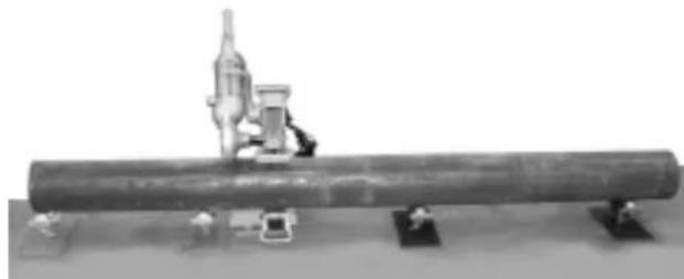
Figure 7A - Longer Lengths
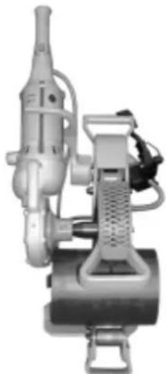
Figure 7B - Very Short Lengths
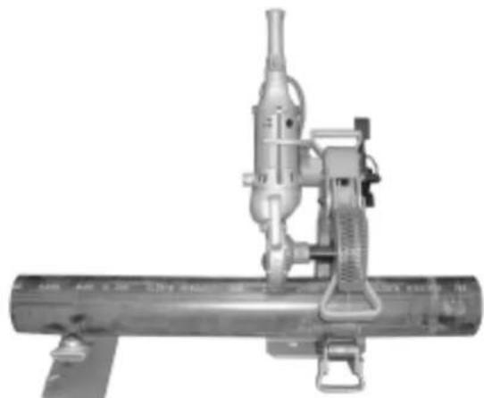
Figure 7C - Short to Medium Length
Operating Instructions
WARNING
Keep fingers and hands away from cutter wheel. Do not reach across cutter or pipe. Keep hands and feet clear of pipe.
Cutter is designed for use with RIDGID 700 Power Drive. Power Drive must be secured by the reaction arm.
Be sure cutter is on a flat, level surface and the pipe is properly supported by pipe stands.
- Be sure pipe is properly supported by pipe supports and will not pinch and damage the cutter wheel.
- Mark the pipe at the desired length for cutting (use chalk or pipe marker).
- Position pipe at marked point to the cutter wheel. Insure pipe is resting squarely on cutter frame rollers. Use foot pump to square pipe to the cutter wheel to avoid mistracking (Figure 8).
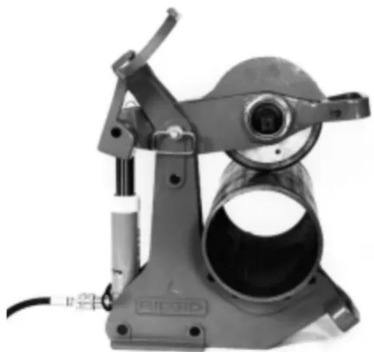
Figure 8 - Positioning Pipe in Cutter
IMPORTANT: Pipe must be free to rotate to perform cut.
- Assure the correct operating position behind the pipe. Exert foot pressure on foot pump. Continue pumping foot pump to advance pivot arm and cutter wheel to the pipe.
- After wheel comes in contact with pipe, pump an
additional 2 or 3 strokes, start 700 Power Drive. The pipe will start rotating once cutter wheel engages the pipe.
- Pump repeatedly (3 to 4 times), this will "seat" the cutter wheel. Allow the pipe to rotate one or two revolutions without pumping.
- Repeat pumping the foot pump three to four times then allow pipe to simply rotate for one or two revolutions before pumping again. Continue this process until pipe is cleanly cut through.
NOTE! Do not pump too aggressively. May distort pipe or damage cutter wheel. Complete at least one revolution before depressing the foot pump again.
Cutting Thin Wall Pipe
NOTE! The 258 and 258XL have a general purpose cutter wheel as standard equipment. This wheel is primarily designed to cut Schedule 40 pipe.
CAUTION Do not use thin wheel on Schedule 40 or greater pipe! Cutter wheel damage will result.
For thin wall pipe (Schedule 10-20) use a thin wheel available as an accessory (see catalog for ordering information).
With the thin wheel installed use the following procedure:
- Position pipe on both pipe supports aligned with cutter.
- Pump foot pump several times to lower cutter wheel onto pipe (do not over pump).
- Pump twice to apply cutter wheel pressure.
- Start the 700 Power Drive.
- Pump once every 5 seconds (3-4 pipe revolutions).
WARNING Do not force cutter. May cause personal injury or wheel damage.
- Repeat above step until cut is complete.
- Number of pumps and cutting time will vary with pipe diameter, schedule and material.
Special Procedures
Adjusting Pivot Arm for Correct Pipe Size (258 Only)
- The 258 is designed to cut pipe from 21/2 through 8 in diameter. The pivot arm holding the cutter wheel must be adjusted depending upon the size of the pipe being cut. The 258 is shipped from the factory with the pivot arm positioned for 21/2 through 4 pipe cutting. To set the cutter for 6 through 8 diameter pipes, do the following:

Figure 9 - Removing Hairpin Cotter and Hitch Pin
a. Remove the hairpin cotter and hitch pin from the pivot arm (Figure 9). Reposition the pivot arm to the locating hole marked, 6 - 8 .HINT: Activate the foot pump to elevate the pivot arm.) Align the hole on the pivot arm with the hole in the cutter frame and insert the hitch pin and hairpin cotter. Use handle on front end of pivot arm to reposition (Figure 10).
NOTE! The hitch pin can be inserted from either side. However, it is easiest to insert the hitch pin from the opposite side of the power drive.
b. Repeat this process when adjusting the cutter for 21 / 2 through 4 pipe. Use the locating hole marked, 21 / 2 - 4 .

Figure 10 - Aligning Pivot Arm
Changing the Cutter Wheel
WARNING
Unplug power cord when replacing cutter wheel or conducting other maintenance.
- To replace worn cutter wheel:
a. Remove 774 square drive adapter and power drive from the square drive.
b. Locate locking nut on opposite side of square drive (Figure 11). With adjustable wrench or 15/16 wrench, loosen nut and remove. Remove washer.
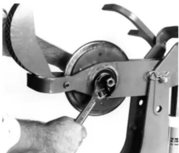
Figure 11 - Remove Locking Nut

Figure 12 - Remove Cutter Wheel Assembly
c. While holding onto cutter wheel assembly, pull drive shaft out and lift cutter wheel assembly up through top of pivot arm (Figure 12). If necessary, lightly tap opposite end of square drive with hammer or wrench to start removal.

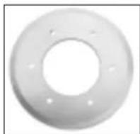
Figure 13 - Cutter Wheel Assembly
NOTE! For multi-piece cutter wheel remove hub on cutter wheel. Locate the three (3) allen screws with lock washers and remove with 1/4'' allen wrench (supplied with cutter). Remove cover plate to expose cutter wheel. Replace worn cutter wheel with new wheel (Figure 12). Replace cover plate and tighten allen screws with allen wrench.
d. Return cutter wheel assembly or new cutter wheel to the cutter. Align square drive shaft with hub assembly and insert until shoulder butts up against inner race of bearing. Place washer and lock-nut on reverse side of square drive. Tighten until locknut bottoms out against washer.
NOTE! Do not over-tighten lock-nut. When nut bottoms out against washer, stop. Over-tightening can reduce wheel's ability to turn, requiring more power from power drive, or it may cause wheel to not track during cut.
- Cutter wheel should easily and freely rotate in either direction when lock-nut is properly tightened.
Transporting
- The 258 and 258XL are designed with hand-holds located at top rear, and bottom of frame front, for transporting the cutter (Figure 14). Do not use pivot arm handle to transport, as it may cause damage to the hydraulic cylinder.
- Remove 700 Power Drive to reduce weight when carrying.
WARNING
Two operators should carry the cutter when being moved to prevent personal injury.
Figure 14 - Hand-holds for Transporting
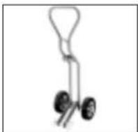
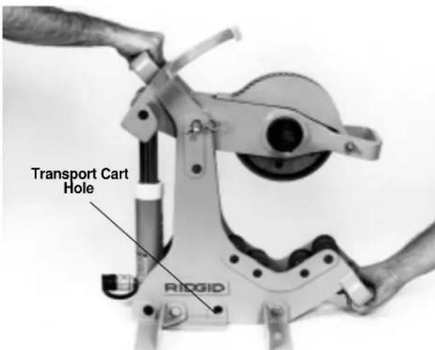
Transporting Using The Transport Cart
A two wheeled cart is available as an accessory to allow for easier transporting. This transport cart, (see catalog for ordering information), is compatible with the 258 (21 / 2 - 8 ) as well as the 258XL (8 - 12 ) . By using a "J" clamp on the top frame handle along with a hitch pin through a frame hole (Figure 14), the transport cart can easily be installed.
NOTE! Transport cart does not interfere with the operation of the cutter and can remain attached.
Maintenance Instructions
WARNING
Make sure Power drive is unplugged from power source before performing maintenance or making adjustment.
- Ensure cutter frame rollers are free to rotate under the pipe. Clean debris, pipe scale, and dirt from rollers.
- Ensure pipe support ball transfer heads are free to move and are clean of dirt, pipe scale, and debris.
- Ensure the three screws and lock washers are tight in the cutter wheel assembly. Periodically check.
- Check fluid levels in hydraulic foot pump. Ensure fluid level is to the full mark when the ram is fully retracted when checking level of fluid. When filling, make sure fluid is added to account for the hose.
CAUTION Use only high grade hydraulic oil when replacing or adding hydraulic fluid.
Machine Storage
WARNING Motor-driven equipment must be kept indoors or well covered in rainy weather. Store the machine in a locked area that is out of reach of children and people unfamiliar with cutting tools. This tool can cause serious injury in the hands of untrained users.
Service and Repair

WARNING
The "Maintenance Instructions" will take care of most of the service needs of this machine. Any problems not addressed by this section should only be handled by an authorized RIDGID service technician.
Tool should be taken to a RIDGID Independent Authorized Service Center or returned to the factory. All repairs made by Ridge service facilities are warranted against defects in material and workmanship.
WARNING When servicing this tool, only identical replacement parts should be used. Failure to follow these instructions may create a risk of serious injury.
If you have any questions regarding the service or repair of this machine, call or write to:
Ridge Tool Company
Technical Service Department
400 Clark Street
Elyria, Ohio 44035-6001
Tel: (800) 519-3456
E-mail: TechServices@ridgid.com
For name and address of your nearest Independent Authorized Service Center, contact the Ridge Tool Company at (800) 519-3456 or http://www.ridgid.com
Troubleshooting
Troubleshooting Table
| Problem Cause Correction | ||
| Foot pump does not advance ram | Hose connections are not complete | Insure hoses from pump to ram are completely secured |
| Low hydraulic fluid | Insure fluid level is at full capacity | |
| Air in hydraulic system | Bleed system | |
| Cutter wheel does not track | Cutter is not firmly clamped to pipe | Insure cutter squares itself to the pipe by pumping several times before starting power drive |
| Pipe is not properly supported | Short lengths of pipe must rest squarely on cutter frame rollers. Long lengths must be supported with stands so the cutter can locate itself to pipe | |
| Cutter wheel has not been preloaded 2 or 3 pumps before starting 700 power drive | Pump 2 to 3 strokes on foot pump after cutter wheel contacts the pipe before starting the 700 Power Drive | |
| Pipe does not rotate | Cutter wheel is not properly assembled | Insure cutter wheel is free to rotate in either direction in hub assembly (See Directions) |
| 774 Square Drive Adapter is not completely inserted in 700 gear head | Square Drive Adapter must be fully inserted, spline first into gear head | |
| Pipe is out-of-round | Insure that pipe is free of flat areas or has not been crushed | |
| 700 motor does not start | Interruption of power supply | Examine supply |
| Fuse blown | Install fuse | |
| Brushes do not touch armature | Check the brushes, renew used brushes | |
| Abnormal heating of motor | Overload because of continuous operation | Let power drive cool after continuous use |
| Insufficient cooling air | Clean the air-vent opening of the motor | |
CONSERVEZ CES INSTRUCTIONS!
CONSERVEZ CES INSTRUCTIONS!
CONSERVEZ CES INSTRUCTIONS!
Technical Service Department
400 Clark Street
Elyria, Ohio 44035-6001
Tel: (800) 519-3456
E-mail: TechServices@ridgid.com
Altura (A) 22 pulp. 27 pulp.
Ancho (B) 11 pulp. 13 pulp.
Technical Service Department
400 Clark Street
Elyria, Ohio 44035-6001
Telefon: (800) 519-3456
E-mail: TechServices@ridgid.com
RIDGID® tools are warranted to be free of defects in workmanship and material.
How long coverage lasts
This warranty lasts for the lifetime of the RIDGID tool. Warranty coverage ends when the product becomes unusable for reasons other than defects in workmanship or material.
How you can get service
To obtain the benefit of this warranty, deliver via prepaid transportation the complete product to RIDGE TOOL COMPANY, Elvria, Ohio, or any authorized RIDGID® INDEPENDENT SERVICE CENTER. Pipe wrenches and other hand tools should be returned to the place of purchase.
What we will do to correct problems
Warranted products will be repaired or replaced, at RIDGE TOOL'S option, and returned at no charge; or, if after three attempts to repair or replace during the warranty period the product is still defective, you can elect to receive a full refund of your purchase price.
What is not covered
Failures due to misuse, abuse or normal wear and tear are not covered by this warranty. RIDGE TOOL shall not be responsible for any incidental or consequential damages.
How local law relates to the warranty
Some states do not allow the exclusion or limitation of incidental or consequential damages, so the above limitation or exclusion may not apply to you. This warranty gives you specific rights, and you may also have other rights, which vary, from state to state, province to province, or country to country.
No other express warranty applies
This FULL LIFETIME WARRANTY is the sole and exclusive warranty for RIDGID® products. No employee, agent, dealer, or other person is authorized to alter this warranty or make any other warranty on behalf of the RIDGE TOOL COMPANY.

Ce qui est couvert
Elyria, Ohio 44035-6001

Que cubre


- Table of Contents
- General Safety Information
- Specific Safety Information
- Description, Specifications and Accessories
- Assembly Instructions
- Pipe Cutter Inspection
- Pipe Cutter and Work Area Set-Up
- Operating Instructions for Cutting Pipe
- Special Procedures
- Maintenance Instructions
- Machine Storage.
- Service and Repair
- Trouble Shooting
- Lifetime Warranty
- 258/258XL Power Pipe Cutter
- SAVE THESE INSTRUCTIONS!
- Work Area Safety
- Electrical Safety
- Personal Safety
- Tool Use and Care
- Service
- WARNING
- WARNING Switch Safety
- Cutter Safety
- Description, Specifications and Standard Equipment
- Description
- Specifications
- Standard Equipment
- Accessories
- Using Pipe Supports
- CAUTION
- Operating Instructions
- Cutting Thin Wall Pipe
- Adjusting Pivot Arm for Correct Pipe Size (258 Only)
- Changing the Cutter Wheel
- Transporting
- Transporting Using The Transport Cart
- Machine Storage
- CONSERVEZ CES INSTRUCTIONS!
- How long coverage lasts
- How you can get service
- What we will do to correct problems
- What is not covered
- How local law relates to the warranty
- No other express warranty applies
- Ce qui est couvert
- Que cubre
Brand : RIDGID
Model : 258XL
Category : Saw