
59G812 - Saw Graphite - Free user manual and instructions
Find the device manual for free 59G812 Graphite in PDF.
| Product type | Miter saw |
| Brand | Graphite |
| Model | 59G812 |
| Rated voltage | 230 V~ |
| Rated frequency | 50 Hz |
| Rated power | 1800 W |
| No-load speed | 4800 rpm |
| Disc outer diameter | 254 mm |
| Disc bore | 30 mm |
| Angular cutting range (table) | ±45° |
| Tilt range (bevel) | 0° to 45° |
| Cutting capacity (0°×0°) | 90 × 280 mm |
| Cutting capacity (45°×0°) | 90 × 200 mm |
| Cutting capacity (45°×45°) | 50 × 200 mm |
| Cutting capacity (0°×45°) | 50 × 280 mm |
| Guide length | 195 mm |
| Protection class | II (double insulation) |
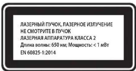
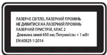
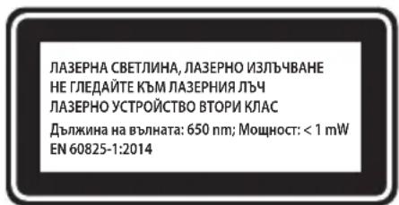
| Laser | Class 2, < 1 mW, 650 nm |
| Weight | 16 kg |
| Sound pressure level | 95.2 dB(A) (K=3 dB) |
| Sound power level | 108.2 dB(A) (K=3 dB) |
| Vibration (acceleration value) | 2.936 m/s² (K=1.5 m/s²) |
| Dust extraction | Vacuum connection and dust bag included |
| Included accessories | Dust bag, special wrench, vertical clamp |
Frequently Asked Questions - 59G812 Graphite
User questions about 59G812 Graphite
0 question about this device. Answer the ones you know or ask your own.
Ask a new question about this device
Download the instructions for your Saw in PDF format for free! Find your manual 59G812 - Graphite and take your electronic device back in hand. On this page are published all the documents necessary for the use of your device. 59G812 by Graphite.
USER MANUAL 59G812 Graphite
e-mail graphite@gtxservice
/EC Declaration of Conformity/
The above listed product is in conformity with the following UE Directives:
and fulfils requirements of the following Standards:/
/Name and address of the person who established in the Community and authorized to compile the technical file:/
/GRUPA TOPEX Quality Agent/
NOTE: BEFORE THE TOOL IS USED FOR THE FIRST TIME, READ THIS INSTRUCTION MANUAL AND KEEP IT FOR FUTURE REFERENCE.
DETAILED SAFETY REGULATIONS
PRECAUTIONS:
- Do not use damaged or deformed cutting discs.
-
Replace the table insert, when it is worn
-
Use only cutting discs that are recommended by the manufacturer and comply with the standard EN 847-1.
-
Do not use cutting discs made of high speed steel.
- Use personal protection equipment, such as: -earmuff protectors to reduce risk of hearing damage, -eye protection,
respiratory system protection to reduce risk of harmful dusts inhalation,
gloves for the maintenance of cutting disc (whenever possible, cutting discs should be held by holder) and other rough materials.
- Connect the dust extraction system when cutting wood.
SAFE OPERATION:
Each time before the saw is connected, check the power cord for damages. Have it replaced in an authorised workshop, if any damage is found.
- Before the saw is connected to the power source, always make sure the supply voltage is compatible with the value specified on the nameplate of the tool.
- Do not allow any unauthorised people, children in particular, to touch the device or its power cord, and do not allow them in your workplace.
- The cutting disc should be selected specifically for a workpiece to be cut.
- Do not use the saw to cut materials other than recommended by the manufacturer.
-
Do not use the saw without its guard or when it is locked.
Make sure the arm is secured during mitre-cutting. -
The floor around the saw should be kept clean and free of any loose materials, such as chips and other waste materials.
- Proper general and local lighting should be provided.
- The litre saw operator should be properly trained in the scope of use, operation and maintenance of the device.
- Only sharp cutting discs should be used. Pay attention to the maximum speed indicated on a cutting disc.
- Make sure the applied spacers and spindle rings are properly used according to recommendation of their manufacturers.
- If the litre saw is equipped with a laser, it is impermissible to replace the laser with a different type. Repairs should be performed by the laser manufacturer or by an authorised representative.
- Before you begin to work, make sure the litre saw is properly secured to the table.
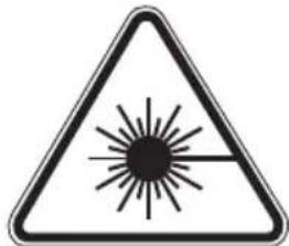
SAFETY RULES FOR LASER DEVICE
The laser device used in the design of the power tool is class 2, with the maximum output of <1mW , at radiation wavelength of 650nm . This device is not dangerous to the eyes, however do not look directly at the radiation source (temporary blindness hazard).
WARNING: Do not use directly at the laser beam. It is hazardous. Always observe the following safety rules.
- The laser device should be used according to recommendations of the manufacturer.
GRAPHITE
- Never deliberately or unintentionally point the laser beam at people, animals or any other object than the workpiece.
- Do not accidentally point the laser beam at the eyes of unauthorised people and animals for the period longer than 0.25 s, for example by point the laser beam through mirrors.
- Always make sure the laser beam is pointed at a non-reflective material. Glossy steel plates do not permit to use the laser beam, since the light might be dangerously reflected towards the operator, unauthorised people and animals.
- Do not replace the laser unit with other type devices. All repairs should be performed by the manufacturer or an authorised person.
NOTE: The tools is intended for indoor works.
Despite using the construction, which is safe by design itself, protection means and additional safety features, there is always a residual risk of injuries during operation.
Descriptions of used pictograms.

1

2
3
4
5

6
- Read the instruction manual, observe warnings and safety conditions included in it!
- Use personal protection equipment (safety goggles, ear protectors).
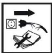
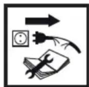
- Disconnect the power cord, before maintenance or repair works are begun.
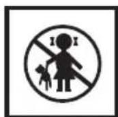
- Keep out of reach of children.
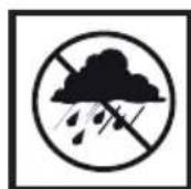
- Protect against rain
- Protection class II

Adjustments other than indicated in this instruction manual may expose you to laser radiation! CONSTRUCTION AND APPLICATION
The litre saw is a device equipped with the base that provides the possibility to change the angle of the cutting head attached to it. In addition, depending on a design, the litre saw head can be tilted at an angle or slid out to increase the functionality and cutting length.
The litre saw is designed for cutting wooden pieces that match with the tool size. Do not use the saw for cutting firewood. Use the litre saw accordingly to its purpose only. Attempts to use the litre saw for purposes other than specified will be considered an improper use. Use the litre saw only with appropriate cutting discs with teeth with sintered carbide inserts. The litre saw is designed for carpentry works in workshops and for joinery works.

The power tool should be used according to its purpose!
DESCRIPTION OF GRAPHIC PAGES
The below list refers to device components shown in the graphic pages of this instruction manual.
-
Transport handle
-
Working table locking knob
-
Handle grip 24. Table insert
-
Switch lock button 25. Working table
-
Switch 26. Laser unit
-
Cutting disc guard lever 27. Fixed guard
-
Spindle lock button 28. Dust extraction connector
7.Cutting disc guard 29.Dust bag
-
Carbon brush cover
-
Vertical clamp locking knob
-
Head locking pin 31. Vertical clamp arm
-
Cutting depth limiter 32. Vertical clamp arm locking knob
-
Cutting depth limiter bolt
-
Workpiece fixing knob
-
Guide locking knob
-
Head tilt angle scale
-
Guide
-
Head tilt angle indicator
-
Head locking lever
-
Battery compartment
-
Fence
-
Laser switch button
-
Table extension
-
Laser
-
Limiter
-
Laser unit mounting bolts
-
Table extension locking knob
-
Centre plate mounting bolt
-
Mounting hole
-
Centre plate
-
Working table angle scale
-
Adjusting bolt for 0^ angle
-
Working table angle indicator
-
Adjusting bolt for 45^ angle
-
Automatic adjustment lever
-
There can be differences between the drawing and real product.
DESCRIPTION OF USED GRAPHIC SIGNS

NOTE
WARNING
FITTING/SETTING
INFORMATION
EQUIPMENT AND ACCESSORIES
- Dust bag
-1 pcs
- Socket wrench
-1 pcs
- Vertical clamp
-1 pcs
PREPARATION FOR WORK

Make sure the litre saw is disconnected from power supply, before any adjusting or mounting works are commenced.
HANDLING THE MITRE SAW

- Make sure the head is locked in the lowest position when carrying the litre saw.
- Make sure that the work table locking knob, head locking lever, and other safety parts are tightened firmly.
INSTALLING THE MITRE SAW ON A WORKSHOP BENCH

It is recommended to fix the metre saw to a workbench or a stand with the use of mounting holes (19) designed for such purpose. They are located on the metre saw base and guarantee safe operation and eliminate risk of unwanted machine shifts during operation. The holes allow to use bolts with hexagonal head and 8mm in diameter.

When fixing the litre saw to a workbench ensure that:
The workbench top surface is flat and clean.
- Screws and bolts are tightened equally and moderately (mounting bolts must be tightened so the base is not stressed or deformed). In case of over-stress there is danger of breaking the base.
DUST EXTRACTION

To prevent dust accumulation and provide maximum efficiency, you can connect the metre saw to an industrial vacuum cleaner using the dust extraction connector (28) Alternatively, you can collect the dust in the dust-bag (included) after installing it onto the dust extraction connector. To install, put the dust bag (29) onto the dust extraction connector (28) (fig. A). To empty the dust bag, remove it from the dust extraction outlet and open the zip-fastener that allows to access inside the bag.

To achieve optimal dust extraction empty the bag when it is 2/3 full.
USING THE EXTENSION ARM (HEAD)

There are two positions of the extension arm - upper and lower. To release the extension arm from locked lower position, do as follows:
- Press and hold down the extension arm.
Pull the head locking pin (9). - Hold the extension arm as it raises to its upper position.
To lock the extension arm in the lower position, do as follows:
Press and hold the disc guard lever (5).
- Release the pressure downwards onto the extension arm until it is located in its lower position.
- Lock the extension arm in this position, sliding the head locking pin in (9).
VERTICAL CLAMP

The vertical clamp (fig. B) can be installed in the saw base at either side of the work table and is fully adjustable to size of the workpiece to be cut. Do not use the saw without using the vertical clamp.
- Loosen the vertical clamp mounting knob (30) to the base on the side, which the vertical clamp will be installed.
- Install the vertical clamp by sliding it into the hole in the metre saw base and tighten the vertical clamp mounting knob (30) to the metre saw base.
- Once the vertical clamp arm position is adjusted (31) to the workpiece, tighten the vertical clamp arm locking knob (32) and workpiece mounting knob (33).
Make sure the workpiece is secured.
OPERATION/ADJUSTMENTS

Make sure the litre saw is disconnected from power supply, before any adjusting or mounting works are commenced. To ensure safe, precise and efficient operation of the litre saw, proceed with all adjustment procedures as a whole.
After finishing all the setting and adjustment procedures, ensure that all spanners are collected. Check that all threaded connections are properly tightened.
When making adjustments, ensure that all external parts work properly and are in good condition. Any worn or damaged part must be replaced by qualified personnel before starting to use the metre saw.
SWITCHING ON /SWITCHING OFF

The mains voltage must correspond to the value specified on the litre saw nameplate. Switch on the litre saw only when the cutting disc is away from the workpiece to be cut.

The litre saw features the switch lock button (3) that protects against accidental starting.
Switching ON
- Press the switch lock button (3).
- Press and hold the switch button (4).
Switching OFF
- Release pressure on the switch button (4).
OPERATION OF THE TABLE EXTENSIONS
The table extensions (16) are located on both sides of the litre saw base.
- Unlock the locking knobs of the table extension (18) (fig. C).
- Adjust the length of the table extensions.
- Fasten the table extension using the locking knobs (18).
- If needed, the tilting limiters can be used (17) to facilitate cutting to size.
OPERATION OF THE CUTTING DEPTH LIMITER
The cutting depth limiter can be used, when it is necessary to make a key in the workpiece. It is performed by making a surface cut in the workpiece, when the disc does not operate at full possible depth.
Lock the head locking lever (14).
- Loosen the guide locking knob (12) and move the head backwards.
- Tighten the guide locking knob (12).
- Rotate the cutting depth limiter (10) to the setting for operation with limited cutting depth (fig. D).
- Lower the extension arm and hold it in the lower position leaning against the cutting depth limiter.
-
Rotate (to the left or right) the cutting depth limiter bolt (11) (fig. D) to obtain the required depth of the cutting disc.
-
Loosen the guide locking knob (12).
Make the cuts to the set depth. -
In order to return to the full cutting depth, rotate the cutting depth limiter (10) to the position, in which the cutting depth limiter bolt (11) does not contact the cutting depth limiter (10), once the extension arm is lowered.
SETTING THE WORKING TABLE FOR MITRE CUTTING
The rotary extension arm allows for cutting the workpiece at any angle in the range of 45^ left or right from the perpendicular position.
- Pull the head locking pin (9) and allow the extension arm to rise slowly to the upper position.
- Loosen the working table locking knob (23).
- Press and hold the automatic setting lever (22) and rotate the extension arm to the left or right so the required value is shown on the angle scale of the working table (20).
- Lock the working table locking knob (23).
The angle scale of the working table (20) has a number of marked positions, in which the preliminary automatic setting of the rotary extension arm is made. This can be done only when the automatic setting lever (22) is not held in the pressed position and it can be locked in factory-marked positions during the rotation of the extension arm. These are the most frequently used metre sawing angles (15^, 22,5^, 30^, 45^ to the left / right). The setting of any angle can be precisely adjusted using the angle scale of the working table (20) with the scale every single degree. Even though the scale is accurate enough for a majority of performed tasks, it is recommended to double-check the cutting angle with a protractor or other device for angle measurements.
CHECKING AND ADJUSTING THE PERPENDICULAR POSITION OF THE CUTTING DISC AND WORKING TABLE
Loosen the head locking lever (14).
- Set the head in the position of 0^ (perpendicular to the working table) and tighten the head locking lever (14).
- Loosen the working table locking knob (23), and press and hold the automatic setting lever (22).
- Set the working table in the position of 0^ , release the automatic setting lever and tighten the working table lock knob (23).
- Press the cutting disc guard lever (5) and lower the saw head to the extreme lower position.
- Use the tool to check perpendicularity of the cutting disc in relation to the working table.

When making measurements make sure that measurement instrument does not touch any cutting disc tooth, otherwise the measurement may be inaccurate due to the thickness of the sintered carbide insert.

If the measured angle is not 90^ , then the following adjustment is necessary:
- Loosen the retaining nut and rotate the 0^ (42) angle adjusting bolt (fig. E) to the right or left in order to increase or decrease the cutting disc tilt angle.
- Once the perpendicular position of the cutting disc and working table is set, allow the head to return to its upper position.
- Holding the 0^ (42) angle adjusting bolt, tighten the retaining nut.
- Lower the head and make sure that the set angle corresponds to indications on the head tilt angle scale (34), if necessary, adjust the head tilt angle indication (35) (fig. E).

Similar adjustment should be made for the angle of 45^ of the head for litre sawing by means of the 45^ (43) (fig. E) angle adjusting bolt.
CHECKING AND ADJUSTING THE PERPENDICULAR POSITION OF THE CUTTING DISC IN RELATIONTO THE FENCE

Perform this procedure each time the fence is removed or replaced. Proceed with the adjustment only after the perpendicularity of the cutting disc in relation to the working table is set. The fence is used as a stop for workpiece.

- Loosen the working table locking knob (23), and press and hold the automatic setting lever (22) and set the working table to the position of 0^ .
- Lower the saw head to the extreme lower position.
- Put a protractor or any other angle measurement tool to the cutting disc.
- Move the angle measurement tool to the fence (15).
The measurement should indicate 90^

If it is necessary to adjust the angle, proceed as follows:
- Loosen the fence mounting bolts (15) to the base.
- Adjust the position of the fence (15) so that it is perpendicular to the cutting disc.
- Tighten the fence mounting bolts.
SETTING THE EXTENSION ARM (HEAD) FOR MITRE CUTTING

The extension arm can be tilted at any angle ranging from 0^ to 45^ - for metre sawing (fig. E).
-
Pull the head locking pin (9) and release and allow the extension arm to rise slowly to the upper position.
-
Loosen the head locking lever (14).
- Tilt the extension arm to the left at the required angle, which you can read on the head tilt angle scale (34) using the head tilt angle indicator (35) (fig. E).
- Tighten the head locking lever (14).

If it is necessary to adjust both angles (in both planes, horizontal and vertical) for combination sawing, always set the litre sawing angle first.
The laser unit emits a laser beam that projects the line on a workpiece that indicates how the workpiece will be cut. The proper adjustment of the laser line projection has been adjusted during the production process. Nevertheless, for precision works, check this adjustment before starting to saw.
- Place batteries in the battery compartment (36) (fig. F) paying attention to polarity.
- Set the working table in the position, where the working table angle indicator (21) is aligned with the point of 0^ on the angle scale of the working table (20), while the head tilt angle indicator (35) (fig. E) is aligned with the point of 0^ on the head tilt angle scale (34) (fig. E).
- Fasten a piece of waste material to the working table (25) and make a cut.
- Release the extension arm and leave waste material fixed to the working table of the saw.
-
Set the laser switch button (37) to the ON position, I^ (marked).
-
The projected light beam should be parallel to the previously made cut.
LASER ADJUSTMENT

When the laser guiding beam is adjusted, do not look at the source of the laser beam or its reflection on a reflective surface. Always switch off the laser unit, when the laser is not used.

Whenever the projected light beam is not parallel to the previously made cut, proceed as follows:
- Slightly rotate the laser to the left or right (38) (fig. G) in the laser unit housing (26), until the laser beam is position in parallel. Do not rotate the laser unit using force and by more than a few degrees.
- When any lateral adjustment is necessary, loosen the laser unit mounting bolts (39) and move the laser unit to the left or right, until the red line is parallel to the cut

Dust arising from cutting may suppress laser light, therefore it is necessary to clean the laser lens occasionally.
STARTING THE SAW

Before the switch button is pressed, ensure that the litre saw is assembled and adjusted properly and accordingly to instructions in this manual.

The described litre saw is designed for the right-handed.
Press the switch lock button (3).
Press the switch button (4).
- Allow the saw motor to reach its full rotational speed.
- Press the cutting disc guard lever (5).
- Lower the extension arm towards a workpiece.
- Release pressure on the cutting disc guard lever (5).
Make a cut.
STOPPING THE SAW

- Release pressure on the switch button (4) and wait until the cutting disc comes to full stop.
- Raise the extension arm of the saw by putting it aside from the workpiece.

Temporary sparking of brushes inside the electric motor is normal when the litre saw stops. Do not stop the cutting disc by applying lateral pressure.
CUTTING WITH THE SAW

The workpiece should be fastened so it does not impede using the litre saw. Before switching the saw on, move its head to the lower position to ensure that the saw head and cutting disc guard are free to move. Make sure the cutting disc guard can reach its extreme position.

Before the cut is commenced, make sure the working table locking knob (23) and the head locking lever (14) of the litre saw are tightened and secured.
-
Connect the litre saw to the power mains.
-
Make sure the power cord is away from the cutting disc and base of the device.
- Place the workpiece onto the working table and make sure it is secured so as it cannot move during the cut.
-
Move the mitre saw heat to the extreme rear position and lock the guide (13) using the guide locking knob (12).
-
Unlock the head and cutting disc guard.
-
Press the switch lock button and start the saw with the switch (wait until the cutting disc reaches its maximum rotational speed).
-
Slowly lower the saw head.
- Start cutting by moderately pressing the head down.

Insufficient tightening of the locking knobs may cause unexpected movement of the cutting disc to the upper surface of the workpiece. It puts an operator to danger of being hit with a piece of material.
CUTTING WITH THE MOVEMENT OF THE SAW EXTENSION ARM (HEAD) OF THE MITRE SAW

The feeding of the saw extension arm allows forward and backward movement of the cutting disc to cut wider workpieces.
- Set the extension arm in the upper position.
-
Loosen the guide locking knob (12).
-
Before switching on the saw, pull the extension arm to yourself while holding it in the upper position.
- Press the switch lock button (3) and start the saw.
-
Release the extension arm and wait until the cutting disc reaches its maximum speed.
-
Release the cutting disc guard.
Lower the extension arm and start cutting. -
When cutting, move the extension arm to the back (away from yourself).
- Once the workpiece has been cut, release pressure on the switch button, and before you lift the saw arm to the upper position, wait until the cutting disc stops rotating.

Never cut by moving the saw head towards yourself. Otherwise, the cutting disc might catch the work piece, which puts the operator in danger of recoil.
Before any operations related to installation, adjustment, repairs or maintenance are commenced, the plug of the power cord should be disconnected from the socket.
CLEANING

- When the work is completed, remove thoroughly all pieces of material, chips and dust from the working table insert, area around the cutting disc and its guard.
-
Ensure the ventilation holes of the motor casing are clean, there are no chips or dust.
-
Clean guides and apply thin layer of solid grease.
- All handles and knobs should be kept clean.
- Clean the laser projector lens with a brush.
REPLACING THE CUTTING DISC

-
Press the cutting disc guard lever (5).
-
Raise the cutting disc guard (7) and loosen the central plate mounting bolt (40) (fig. H).
- Move the central plate (41) to the left to provide access to the cutting disc mounting bolt.
- Press the spindle lock button (6) and rotate the cutting disc until it locks.
- Using the special spanner (included), loosen and unscrew the cutting disc mounting bolt.
- Remove the external washer and remove the cutting disc (paying attention to the reducer ring, if provided).
- Remove all impurities from the spindle and cutting disc mounting washers.
- Mount a new cutting disc by performing the described activities in a reverse order.
- Once completed, make sure all spanner and adjusting tools are removed and all bolts, knobs and screws are tightened and secured.

The cutting disc locking bolt has left-hand thread. Exercise utmost attention when gripping the cutting disc. Use protective gloves to provide protection for your hands against sharp teeth of the cutting disc.
REPLACING BATTERIES IN THE LASER UNIT

The laser unit is powered with two AAA batteries, 1.5 V.
-
Open the battery compartment lid (36) (fig. F).
-
Removed used batteries.
- Insert new batteries. Observe the polarity.
- Installed the battery compartment lid.
REPLACING THE CARBON BRUSHES

Worn (shorter than 5mm ), burnt or cracked motor carbon brushes should be immediately replaced. Both carbon brushes should be always replaced at the same time.
-
Loosen the covers of the carbon brushes (8).
-
Remove the worn carbon brushes.
- Remove any carbon dust using compressed air.
- Insert new carbon brushes (brushes should easily slide into the brush holders).
- Fasten the covers of the carbon brushes (8).

After the carbon brushes are replaced, switch on the tool with no load and wait for 1-2 minutes to make the carbon brushes fit the motor commutator. Carbon brushes should be replaced by a qualified person using original spare parts only.

All types of faults and defects should be eliminated by an authorised service of the manufacturer.
SPECIFICATIONS
RATED DATA
| Mitre saw | ||
| Parameter Value | ||
| Power supply voltage 230V~ | ||
| Power supply frequency 50Hz | ||
| Rated power 1800W | ||
| No load spindle speed: 4800min | -1 | |
| Angle sawing range ± 45° | ||
| Mitre sawing range 0° ÷ 45° | ||
| Outside diameter of cutting disc 254mm | ||
| Hole diameter of cutting disc 30mm | ||
| Workpiece dimensions angle/mitre | 0° × 0° 90 × 280mm | |
| 45° × 0° 90 × 200mm | ||
| 45° × 45° | 50 × 200mm | |
| 0° × 45° 50 × 280mm | ||
| Guide length | 195mm | |
| Laser class | 2 | |
| Laser power | < 1mW | |
| Laser wavelength | λ = 650nm | |
| Protection class II | ||
| Weight | 16 kg | |
| Year of manufacture | 2019 | |
NOISE AND VIBRATION DATA
Acoustic pressure level: Lp_ = 95.2 dB(A) K = 3 dB(A)
Acoustic power level: LW_ = 108,2dB(A) K = 3dB(A)
Vibration acceleration value: a_n = 2,936m / s^2 K = 1,5m / s^2
ENVIRONMENTAL PROTECTION
Electrically powered products should not be disposed of with household wastes, but should be utilised in proper recycling centres. Obtain information on waste recycling from your seller or local authorities. Used electric and electronic equipment contains substances active in the natural environment. Unrecycled equipment constitutes a potential risk for the environment and human health.
"Grupa Topex Spółka z ograniczona odpowiedzialnoscia" Spólka komandytowa with seat in Warsaw at ul. Pograniczna 2/4 (hereinafter Grupa Topex) informs, that all copyrights to this instruction (hereinafter Instruction), including, but not limited to, text, photographs, schemes, drawings and layout of the instruction, belong to Grupa Topex exclusively and are protected by laws accordingly to Copyright and Related Rights Act of 4 February 2004 (ustawa o sprawie autorskim i prawach pokrewnych, Dz. U. 2006 No 90 item 631 with later amendments). Copying, processing, publishing, modifications for commercial purposes of the entire Instruction or its parts without written permission of Grupa Topex are strictly forbidden and may cause civil and legal liability.
MEPbI IPEOCTOPOXHOCTN:
3aippeaaetcpa60TaTcnoBpeKdEHHbIMNnnDeΦOpMnPoBAHbIMNnIbHbIMN dNCKaMn.
3aMeHnTe BknaDbIbI cTOna B cIyueae erO n3HoCa.
Pa3pewaetcpa6oTaTb c nIbHbIMn dNCKaMn, peKOMeHIOBaHHbIMn npOn3BOIDTeIem m OTBeuaOUMn Tpe6OBaHnM cTaNdapTa EN 847-1.
3anpeaetca nCnOlb3OBaTb NnBhIe DnCKn 36bictpopexyuie CTaII.
-ПользуITEcB cpeCTBaMn INHINBnDyaJIbHOJ 3auntbl, TaKIMN KaK: -3aunTHbIe HayuHnKnДЯпpeDToBpaUeHnI NOTePn Cnyxa, -CpeCTBa 3aunTbI rla3,
cpeCTBa 3aunTbI DblXaTeNbHbIX NyTeIN DnA COKpaueHnBdbIxAHn BpeHOH nbln,
pa6oynpe npaTkn IJRA pa6Otblc nIbHbIMn DnCKAMn INpoUHM OCTpbIMMaTePnAamn (ecnn BO3MOXHO, NIIbHbIe DNCKN CNeDyET PnpIepKINBaTb 3a OTBepCTne).
BoBpeMa paCnHaIpeBeCnHbI NpOKnIOuAaTe CnCTeMy BblTAAKKN PbIIN.
BE3OPIACHARPABOTA:
Bcerda nepeB BKIOUeHHeM PnIbI npOBepaTe UHP nHTAHN, a B CJIyae erO NOBpeKdEHN o6paTntecb B cepBcHbI ueHTp dIra 3aMeHbI shHypa.
- Bcerda nepeB BKIOUeHnEM nIbI b PO3ETky y6eINTEcb, YTO HAnpJKeHne cTeN COOTBeTCTByET HApJKeHnIO, yKa3aHHOMy B nAcNtOpTHoTbIuKe nIbI.
He pa3pewaTe npikacatbca K nIe IINu shHpy nITaHnnoCTOpOHnM nUaM, npexKe BCero, dETAM; He pa3pewaTe nM haxoDntcB pa6oey 0he nIbl.
- Пильный диспоста в заимости от тура матерпала, пedingаизногдя раслila.
3anpeaetcnaonb3oBaTb nny dny paenla MaepnnaOB, He pekomeHdoBaHHbIX npou3BOUnteMe nnbl.
3anpeaaetcpa6oTaB cnnno 6e3 3aunTHoro Koxyxa nnn ecnn 3aunThbIKoxyx 3a6nOKnpoBaH.
- Пин НОнном пашил eубeintecb,чTo пeунпилbl HaedxHo 3aФИКс�рВаH.
- Пал в pa6оeн зоне пиь coхpaHЯTe B uHcTоTe, 6e3 пшнx MaTePuaNoB, CTpyKn n npOuNX OTXoIDOB.
-
Oecnepty Heo6xOJHMOe o6uue uIIMcTHoe ocBSeHHe.
-
OnepaTop Должень 6ыть 03нakомпен с пабиами Ксплуаци, обчхьаняплы И Тхнческого ухая за плоб.
- Плььтугсь толъко OCTьIMипьньим ДИСКами,обрацай Te BHMmaHne Ha MaKcIMaJIbHyIOCKOPOCTb,yKa3aHHyIHa ПиьнHomДИСKE.
- Y6eIntecb, yTO nCNoB3yEmbIe IINCTaHcUHHbIe 3JIeMeHTbI IN KOnbua WnIHdEJIy UCTaHOBHebl B COOTBeTCTBUN C peKOMeHdaUaMn PpON3BOIDTeJI.
- Ecnn nIIa OchauheHa Ia3epHbIM yCTpoiCTBOM, erO 3aMeHa yCTpoiCTBOM dpyrOTo Tnna KaTEROpuYeCKn 3anpeueHa. Pemont dOnJKeH BblONHrtb npOn3BOoNTeJIb Ia3epHOrO yCTpoiCTBa nn erO yNoIHomOueHHb II ppeCTabUTeJIb.
- Пистусяй К рабов, поверьтей крpenлений ппьк рабочу-stoly.
ПРABИАТEXHИКBE3ОПАСHОCTNПИРAPABOTEСЛA3EPHBIMYCTPOICTBOM
Ja3epHoe yctpoinCTBO, nCNoIb3OBaHHoe B KOHcTpyKuIN 3NeKtpoiHcTpyMeHTa, OTHocITcK Ja3epHbIM YcTPOInCTBaM 2 KnaCa, MaKcMaIbHa MoUHOCTb CoCTaBnEeT < 1 MBt, dNHa BoNhbI Ja3epHoro n3nyeHnA
-650HM.DaHHoe yctpoIcBO He ABLaETcO NaCHbIM dIg 3peHnO,ODHaKO,3aPepaETcCmOTpeTb Ha NCTOuHnK u3nyehn (OnaCHOCTB BpeMeHHo CJIeNtbl).
IPEIOCTEPEXHENE.3anpeaaetc mOteB napehnyok.3To onacho.Co6JIOaTe npabnataTexHKn 6e3oNaCHOCTN.
- La3epHoe yctpoNCTBO cneJeT nCNOJb3OBA Tb B COOTBeTCTBn C yKa3aHnA M N pOn3BOJNTeJ.
3anpeaaetc ymbiHHeHHn HeMbIeHHo HappaTb naepHbI lyu Ha IIOe, KINBOTbIX nnn npyro onBeKT, Kpome 6pa6aTaBaemoro MaTepnana.
3anpeaetc co3daBbCnTuau, cnoc6ctByoune HnpedHaMepeHHOMy HanpaBHeHIO na3epHoro lyuBa rna3a IIOe HxNBOThbIX B TeueHne 6oone 0,25 cekyHd, HapnPmep, HappaBnaIa3epHbI Lyu C nOMOsbIO 3epkana.
Heo6xmo y6eHtbcB TOM, 70 Na3epHbI Nyu HnPaBneH MaTePnaI, He ImeOuI M OtpaKaHux IOBepxHOcte. Bnctraa JnCTOBaC TaIb He Ns3BOJraT pa6OtaTb C Na3epHbIM LyUOM, TAK KAK 3TO MOKeT BblBaTb ONaCHOE OTPaKeHne LyuB HnPaBNeHm OnpaTopa, NOCTOPOHHX IInu X JNBOTHbIX
3aIpeaaetc3aMeHbIa3epHoe yctpoNCTBO yctpoNCTBOM HHO Tnna.PeMOHTdoJxHeH npOBoNTb npOn3BOOHTeNb IyNtHOMOeHHb CneuaJIcT.
BHIMAHHE: O6OpydoBaHne cnjxnt Ipa60tBHytpn nomeueHn.
Hecmotpr Ha 6e3oNaChyio KOHCTpyKcIIO, npednpnHaTble 3aunTHbIe Mepbl NcnoJb3OBaHne cpeCTB 3aunTbI, Bcerda cyueCTByeT HeKOtOpbl OCTaToUHbI pNCK nOlyuHn TpaBMbl BO BpeM pa60TbI.
PacwnpobkAnIKTORpamM

1

2
3
4
5

6
- IpoountaTe HNCTpyKuIO NO 3KcNpyatauIN, co6JIoJaTe yKa3AHnI INpaBnla TexHnKn 6e3onacHOCTn, npBedeHHbE B IHCTpyKuIN!
- Nolb3yntcB cpeCTBaMn HnHnBnDyanalbHOH 3aunTbI (3aunTHbIMN OOKAMN, HayuHKAMN)
- OTKJIIOUHTe UHyp pIITAHn Ipeep peMOHTHO-HaIaNooHbIM pa6oTAMn.
- He pa3pewaIe Tepn npKacbca K 3JeKTPoHnHCTpyMeHTy.
- 3aunuaTe oTdoKnBnaR.
- 3neKtpoHnCTpyMeHT II Knacca 3aunTbI.

HactpoikKa na3epa, BbIXOJaIa 3a paMKn OINcaHHoB DaAHHom pyKOBoIcTBe, UpeBaTa onaCHocTbIO na3epHoro 6bIyehnI!
KOHCTPYKUNI INPIMMEHEHNE
TopoBOUHnI npedctabIeT co60I nIbHyIO roIOBky, 3aKpeNHeHHyIO HaI pa6OUM cToIOM, C BO3MOxHOCTbIO n3MeHnI yrIa ee HAKIOHa. IOnONHHTeNbHO, B 3aBNCIMOCTN OT KOHCTpyKcII, IIbHyIO rOIOBky TopoBOUHnI nIbMoXHO HAKOHrTb NOD ONpeJeHHbIM yrIOM, a TaKKe BblBnraTb dIyBEJIuHEnHMyfHKUHOHaJIbHOCTn I dINHbI pOPIIla.
Topoobouha nna npedha3haeHa dpaacnunBaHn 3arOTOBOK n3 dpBeCnHbI, pa3Mepbl KOtOpbIX COOTBETCTBYOTpa3Mepynnbl.3anpeaaetcncnonb3ObaTb nnnydnapcnnaDPOB.3anpeaetcnpimehrTb Nnly He no Ha3NaueHIO. NOnblkncnoB3OBAHn Nnbl dner cene, He peKomeHdoBaHHbX B daHHo IHCTpyKUIN, CHTaOTc npimeHeHem INCTpyMeHTa He no Ha3NaueHIO. Nnla doJnxHa NCNOB3OBAtbcra
NCKIQUHEnbHO C COOTBeTCTBMyIMN NINbHbIMN DnCKaMNC TBePDCnnaBhbIMN HanaKaMn. Pnna npEHa3HaueHa dner leKnx cToJIrpHbIX n IIOTHNuKnx pa60T B MaCTepcKoN.

3anpeaetc npimehrB 3neKtpoHCTpymEn He no Ha3HaueHIO!
ONICAHNE K TPAQUeCKM N3OBPAXEHNAM
IpeueHneHHa Hnke HymepaunKaacaeTcnaemeHTOB INHCTpyMeHTa, npedCTaBneHHbIX Ha cTpaHnucx C rpaHnuecknMn n3o6paJaceHnMn.
- BLOKINPOBOHbI 6oNT pa6oery cTOna
5.PbIur 3aIHTHORO KOKyxa NINbHoro INska 27.HeNoBnKbIK KOxuyx
- Puyka dnia nepeHoNCKn
- PykOaTka 24. BklaabIbI cToIa
3.БLOKnPaTOp KHONKn BKNIOUeHn 25.Pa6OCh n CTOn
4.KhONKa BKNIOUeHn26.La3epHbIMoDyIb
6.KHONka 6IOKUPOBKNIINHIDeJI 28. NaTppy6OK OTbOda nbJIn
7.3aunTHbIKoKxyNIIbHOrO duCKa 29.IbIe6OpHNK - KpbIuKa yroIbHoI ueTkn
- CTepeHeB fHKcauIN NnIbHOI rONOBKIN
- OrpaHnHTeB rny6nHb paCnna
- BnHT orpaHnUHTe rny6uHb paCnHa
- BLOKINPOBOHbI 60Tn HAnpaBIAIOe
- HanpaBnIouaI
- Pbyar 6JIOKINOBKN INJIbHOI rONOBKN
- Планнka-огранчтелb
- ydnnHnteIb cTOna
- OrpaHnHTenb
- BLOKIPOBOHyB 60T yDInHnTeJr CTOna
- MoHTaXHoe OTBepCTne
-
lka nra haknoha pa6oero ctoa
21.Индikatopуглpa6oeryo cToIa
22.PbIur aBtOMaTnHeCKo HaCTPOIKN -
Kpenexhbl BnHT BepTKaJIbHOrO 3aKIma
31.Плесу Вертукально зжима - BLOKINPOBOUHbI 60JIT npea BepTnKaJIbHOrO 3axkIMa
- Φικατορ 3aσοτοκη
34 ⅢkaIa yIra Na HAKIOHa NIIbHOI rOIOBKn - INHdkaTop yrna HaKIOHa NIIbHOI ROJOBKN
- Otcek 6aTaapeek
- Khonka BkHoueHna3epa
- Na3ep
- Kpenexhblb BnHTbI na3epHoro Moyna
- KpenexHbIe BnHTbl ueHTpaIbHOI nlaCTnHbI
- LcHTpaIbHaI INaCTnHa
- PerynipobOHybI BnHT yIa 0^
- PerynipobOHyB BnHT yrna 45^
* BheuHn BvD npno6peTeHHoro 3JIeKTpOHCTpymeHTa MOxEt He3HaHTeNbHO OTNuaTbCra OT N3o6paXeHHoro Ha pncyHke
PACUHΦPOBKA INPEUINPEXIAIOUX 3HAKOB


BHIMMAHNE
BHIMAHHE-ONACHOCTb!
C6OPKA/HACTPOIKA
NHΦOPMALI
OCHAUHNEI DONOLHNTBHBIE PNHAJEXKHOCTN
1.Пылесборнк
-1wT.
2.CneuaalbHbI KJIIOU
-1wT.
- BepTnKaJIbHbI 3aJxIM
-1wT.
IOnIroTOBKA K PABOTE

Ipnctyna K IIO6bIM MOHTaxhblIM nIN perynlpOBOyHbIM pa6oTaM, y6eINTecb, qTO TOpcoBOUHa
NEPEMEUENIEIJIbI

BKJIIOUeyHE/BbIKJIIOUeyHNE

Hanpajxehne cetn doJXHO COOTBeTCTBOBaTb Hapjxehu, yka3aHHOMy B nacnpTHo Ta6JnUke nnbl.
MOnKHO BkIIOHTb npu ycIOBm, YTO NJIbHbI DNCK He npNKACAeTcK 3aROTOBKe, npedHa3HaueHHo Ira pacnNlNBAHna.

TopoBOUHnA Hnla HMeET 6IOKnpaTOp KHOIIKN BkJIIOueHnra (3), IpeIOxpaHnOuIiN OTHePipeHaMepeHHORO BKJIOueHnra.
BkIoueHne
HaKMHTe KONKy 6IOKnpaTopa (3).
- HaKMMTe HπpHερχNTE KHOIIKy BKIIIOUeHHa (4).
BbiknIOueHne
- OTnyCTHTe KHOIIKy BkIIHOueHnA (4).
OBCLYKUBAHNE YJINHHTENEI CTOJA

-
YДЛИНТЕПСТOLA (16) paCIOJIOKeHbI C DBYx CTOpOH OCHOBaHHЯ ПИЛы.
Pa36IOKpyTe 6IOKINPOBOHbIe 60JIb yIHHHTeJe CToJa (18) (pnc.C). -
OtperynpyIte dHy yIHHTeJe cToJa.
-
3aKpeHHTe C I IOMOIOBIO 6JIOKHPOBOBybIX 60JTOB yDINHHTeJIe CTOJa (18).
- EcJIN Tpe6yeTcR, MOXHO BOCIOJIb3OBA TbC8 OTKHINbIMN ORpaHHHTeJIaMn (17), o6JIerTuHOIIHMn pe3Ky 3aROTOBKn Ha KycKn ONpeJeJIeHHoI JInHbI.
OBCLJXKUBAHNE OPGAHNUHTEJI TLYBUNHbI PACINILA

OrpaHnUteIem rny6uHbI paCnHa moXHO BOCNoB3OBAtbcra B clyaee, KOrda Heo6xOIMo CdeJaTb na3 B MaTePnaIe. Iyra 3TOrO Ha NoBepXHOCTu 6pa6aTBiBaEMoro MaTePnaIa DeJaETc Hndpe3, npn 3TOM NnHbI dNCK He pa6oTaET Ha nonHyIO rny6uHy.

IPOBEPKA PABOTbl JIA3EPA

Ja3epHoe yctpoiCTBO rehepnpyET Ja3epHbI lyu, HameaIOUII JINHIO Ha 3aOTOBKe, NO KOtopoI 6ydet NITN PnIbHbI DNCK BO BpeM paCnIIa. Ja3epHoe yctpoiCTBO OtperyI npoBaHO a6pnuHO. OHaKO B cIyue ppeuznHOrO paCnIIa nepeI hauJOM pa60TbI cIeJyET npOBepuTb dAnHyIO hAcTPOIKy.
BCTaBbTe 6aTapeN B OTCeK dIg 6aTaapeek (36) (pnc. F), c co6nIOJeHneM nOJIrpHOCTn.
- YctaHOBnTe pa6oOuN CTOn B NOJoxKeHne, npu KOTOpOM INdNKaTOp yrNa HaKIOHa pa6oOero cToNa (21) COBnaJaET C OTMeTKoN 0^ Na ⅢKane yrNa HaKIOHa pa6oOero cToNa (20), a INdNKaTOp yrNa HaKIOHa INIbHOI rONOBKn (35) (pnc. E) COBnaJaET C OTMeTKoN 0^ Na ⅢKane yrNa HaKIOHa INIbHOI rONOBKn (34) (pnc. E).
3aKpeHnTe Ha pa6oem cToIe (25) HeHyxHbI KycOK MaTePnaJa IJra TeCTnPoBaHnI N BblOnHnTe npo6HbI paCnnJ.
- OTnycntte nneO nocTaBbTe Kycok MaTePnanaHa pa6ooyem CToJe nnbl.
- PepeKJIouHTe KHOJky BKNIOUeHnJa3epa (37) B NOLOXKeHne „BKNIOUeHO" - "I" (B COOTBeTCTBUN C OTMeTKoJ).
- Tenehpuyembl na3epHbI lyu doJxhen npoxoDnT bnapaJIeBHO BbINOnHeHHomy nponny.
PERYJINPOBKA JIA3EPA

Bo Bpemr perynnpobkn na3epnoro lyua 3anpeuaeTc rcmotpeb Ha na3epnbI ny nI er o TpaKeHne B 3epkabHOIOBepxHocTN. CneJeT bblKnluOaTb na3ephoe ycToICTBO, eCNI OHO He IcNOnb3yeTcR.

Ecnnaaepnny He 6ydt npannenBbInonHeHHomy npOnny, cneyny:
Cnerka nobepHytb na3ep BneBO nIN BnpaBO (38) (pnc. G) B Kopnyce na3epHoro Moyla (26), otperynipobab napannenbHOe noLoXeHne na3epHoro lyua. He cIeNyET hacnBHO nobopauBaTb na3epHbIMoDybl Ha 6Oblwe, yem HeckolbKO rpaYcoB.
- Ecnn Tpe6yetcnaonepeuHnapeynipOBka, ocna6bTe KpenexHbI BnHTbI na3epHoro Moynr (39) n nepemecnte na3epHbIMoynb BnEBO nnBnpaBO, yTo6bl Na3epHbIMny 6bl npapannenEn BblONHHOMy nponny.

Пыль,обрауюцаяв В Берma paclnilBaHnna,MOKeT Chn3ntbЯркoctb La3epHoro lyua,no3Tomy LInH3y npoeKtopa Heo6xOdmo nepnoDnueckn OuHsaTb.
BKJIIOUeyHNEIINbl

Ipeed haxaTneM KHONKn BkIIOueHn y6eIntecb, YTO nIIa HApExHO 3akpenHeHa n OtperyIpObaHa B COOTBeTCTBmN CyKa3aHnMn, npNBedeHHbIMN B DaHHo INHCTpyKuMn.

Пиla npedha3HaueHa ДЯ npabOpkyx NOlb3ObaTeJIe.
- Haxmnte 6nokupaTOKHONK BKNIOueHn3.
HaxmTe KhoNky BkNoueHn4.
-ДаиTe ДИВагATEJINoHa6paTb NOHHyO CKOpOCTb BpaUeHnIa.
- Haxmnte Ha pbiur 3aunTHoro Koxyxa nnbHoro dncka (5).
- Pn6JIn3bTe nIeO nINbIK 3aROTOBKe.
- OTnyctnte pbIur 3aunTHoro kOxya nnbHoro nUcKa (5).
- Pnctynnte K pacnnnBaHnIO.
OCTAHOBKA NINJIbI

- PepecTaHbTe HaxnMaTb Ha KONky BkIoueHn (4) nnoOxKdTe, yTo6bl NnBbHbI dNCK NOHOCtbIO nepectaBpaaatbcra.
- POnHnMnte nIneO nIIbI, oToDnBraer erO ot 6pa6aTbBaemOn 3aTOrTOBKn.

KpaTKOBpeMeHHoe NCKpeHne ΜeTOK BHyTpN DnBraTeJI YBnEaTc HOpMaJbHbIM YBJIeHNEM BO BpEm BKNIOUeHnI N OCTaHOBKn NIIbl. 3aIpeuaetc OCTaHaBnBaTb NIIbHbI DNCK, HaxkImaH Ha Hero c6Oky.
PABOTACIIIOI

3arotOBky 3akpenIyTe TaKIM 06pa3OM, yTO6bI 3TO He MeuAo pa6oTe cNiloi. Npeed BKnIOueHneM nIbI nepemectte nIbHyIO rOLOBky B HnXHee noIOxKeHne u6eINTecb, yTO nIbHa rOIOBka u 3aHTbIKoKyx nINbHOrO dNcKa IMeOT CBO6Oy DnIXKeHna. Y6eINTecb, yTO BO BpMa DBNXeHna 3aHTbIKoKyx nINbHOrO dNcKa onyckaetcdo CaMOrO HnXHero noIOxKeHna.

PpncTyna K pa6ote, y6eHntecb HnadeXHO 3aTJxke 6NoKnpoBOUHO 6OHTa pa6oeryo cTOna (23) n pbuHa 6NoKnpOBKn nnBHO rOLOBKn (14).
BknHHTe NnJy BceTb.
- Y6eIntecb, yTO WHyp NITaHnHa HaxoNtCra Ha 6e3OnaChom pacCTOHN OT NINbHOr OuCKa.
- IonoXte 3aIOnOBky Ha pa6ouH CToH npOBepbTe HAdexHoe KpeJIeHne 3aROtOBKn, YTO6bl OHa He nepemeuaacb BO BpempaCnunBaHH.
- Iepemecnte nIbHyIO roIOBky B KpaHHee 3aJHee noIOxKeHne, 3a6IOKpyTe HappaBnaOyU (13) c nOMoBIO 6IOKpOBoHOrO 6OIta HappaBnaOuEi (12).
Pa36nokpyTe nnbHyIO roJOBKy n 3aunTHbI KOxUx nnbHOrO dNcKa.
HaXMMTe Ha 6IOKnPaTOp KHOKN BKNIOUeHnA, BKNIOUHTe NNIy KHOKNBKNIOUeHnA (daIte NINbHOMy DnCKy Ha6paTb MaKcMaJIbHyIO CKOPOCTb BpaueHnA).
MeDneHNO onyckaIte nIbHyIOJIOBky. - HauHaiTe paCnINBaTb MaTePnaI, yMepeHNo HaxNBa Ha roJIOBky BO BpEmpaacnINBaHnA.

Hehaexnna 3aTkKa Kcnpuux BnHTOB MoKet BbI3BaTb BbIXoNHLbHOrO dNCKa Ha NOBepxHOCTb 3arOTOBKn, a Oneapop MoKet NOnyUHTb TeleChble NobpeXdHnB pe3yNbTaTe yDapa o6pa6atbIAeMoN 3arOTOBKOJ.
PACNJI C NEPEMELEHNEM ILEEA (ROJOBKNI) NJIbI

Bo3MoXHoCTb nepemEeHnna npea o6ecneuBaet DnuXeHne nnIbHorO daHa3aN Bnpeed dna pacnnnBaHH 6oJee uPOKnx 3arOTOBok.
- YctaHOBNTe PJIeO B BepxHem NOJIOKeHN.
- Ocna6bTe 6noknpoBOHyB 60T HappaBriauoei (12).
- Pered BKluyeHem nIbI notaHnte IneuHa ce6, npndepKnBa ero B Bepxhem noJoxeHn.
Haxmnte Ha 6noknpatop KhoNk BkNoyeHna (3) n BkNoHTe nnny. - OTnyctnte nIeYo, daiTe nnHomy dNcKy Ha6paTb MaKcMaJbHyIO CKOpOCTb BpaJeHnA.
Ocbo6oDnte 3aunTHbIKoKxy nIJIbHOrO dNcKa.
Onyctte nneyo npctynte k pacnnuBaHIO.
BoBpempa60tbBeDnte nIeHoHa3aO (OTce68).
3aBepuBpa60Ty,OTnycNTbKHOJky BKNIOUeHnI DOXdntecb NOJHO OCTaHOBKn NINbHOrO dNcKa,a 3aTeM NoHNmTe Pneo B BepxHee NNoXKeHne.

3anpeaetcBO Bpempa60tBeCTn NnBHyIO rONOBky Ha ce6y. NnBbHbI dNCK MoKeT BHe3anHO BBICKOHTb u3 aROTOBKn N Bbl3BaTb 6oPaTHbI yap, qTo oueh b onaCHO nla onepaTopa.
OBCLYXUBAHNEI KOHCEBALM

Ipnctynaj K yctaHOBke, perylnpOBKe mnn peMOHTHO-06cnyXnBaIOUm pa6oTam, Heo6xOIMMo BbInyTb BNk Ky shypa nNTAHn nnblb n3 pO3eTKn.
甲CTKA

- После заевшипаяразы удалие Ск КусmaТериа,очиртЕВКlaДьш pa6oherO CTOna,облacrBOKpyr nInbHOrO dNcKa n Koxyx nInbHOrO dNcKa O T cTpyKn n PbIIN.
- Y6eIntecb,чTO BeHTnJIauIOHHbIe OTBepCTnKopnyCa DBuRaTeJI He 3aKynOpHeN bIbIbIO nCTpyKkoJ.
OuHCTnTe HnpaBraIouIe N nokpoTc cIooM TBepdoi CMa3Kn.
Bce pykoTkn,6JIOKpaTopblnIKCaTopbIcoxpaHnTeBnCTOte.
- LIn3y npoeKtopa na3epHoro yctpoiCTBa oUnlaTe KICTOUkO.
3AMEHA NIIbHORO DNCKA

- Haxmnte Ha pbiur 3aunTHoro koxya nnbHoro dcca (5).
- Повимпеташит biom koxyx nibHoro duCKa (7) n OTbHTnTe KpeNXbBnHT cHTpaJbHOI nactHHb (40) (pnc. H).
- OToBnHbTe ueHTpaIbHyIO nlaCTnHy (41) BJIeBO TaK, YTO6bl NOnyUHTb DOCTyn K KpeNexHOMy BNHTy NNbHOrO DNCKa.
- Haxmnte Ha 6noknapatop nnHdela (6) nOBepHnte nnbHbI dNcK, yTo6bl 3a6noknpoBaTb erO.
C NOMOUI CNEUaJIbHOrO KIIIOuA (BXoIIT B KOMNIEKT PIIbI) Ocna6bTe I Bblte KpeNEXHbI BNHT IIINbHOrO DNCKa. - CHIMITE BHESHHIOU Wai6y, BBHbTe NINbHbI DNCK (O6paaJra BHIMaHne Ha nepexoHoe KOJIbQO, ecnNmeeTc).
OuNCTnTe 7nnHdIe N KpeJnxHbIe 7aI6bl nIbHOrO dIcKa OT BCEx 3aIpr3HeHH.
3aKpeHnTe HOBbI DNCK, BbINOJIHrA nepeUncIeHHbIe BblIe DeIcTBnB O6paTHoNocIeIOBaTeIbHOCTn.
3aBepuB 3aMeHy dNcKa, y6eHNTecb, YTO Bce KIOUHy I npOHy peYInpoBOHyI INCTpyMeHT y6paH, npOBepbTe 3aTJkKBy BNHTOB, 60LTOb I nIKCaTOPOB.

IpeoxpahntenbHbI BnHT nHbHoro dNcKa IMeET jeByo pe3b6y. PpnKacacb K nnHbHomy dNcKy, co6nOaTe npedEnbHyIO octopoxhocTB. Nob3yIteCb 3aunTHbIMN nepuATkAMN, UTO6bl 3aunNTb pyKn OT KOHTAKTa C OCTpbIMN 3y6bAMN NNbHoro dNcKa.
3AMEHA BATAPEB JIA3EPHOM YCTPOICTBE

Ja3epHbMyDyIb nIaTeTcO TdByx 6aTaapeek 1,5B Tuna AAA.
- OTKpoIte KpbIshky oTceKa dIЯ 6aTapei (36) (pnc. F).
BbInbTe nCnOJIb3OBAHhbIe 6aTapeN.
BCTaBBTe HOBbIe 6aTapeu, co6JIIOJa nOJIaRHOCTb.
3akponTe KpbIshky OTeKa dny 6aTapei.
HHOPMALUOBYPOBHE WUMANBUNPAUIN
YpOBeHb 3BykoBOrO daBHeHnA: LpA=95,2 dB(A) K=3 dB(A)
YpoBHeB 3ByKOBoM OuHocTu: Lw=108,2 dA(K=3dA(A)
Bn6poycopoeHne: a=2,936 m/c² K = 1,5 m/c²
3AUHTA OKPYXAIOUI CPEIbI
3NeKtpoPn6OpbIHe CneJeT Bb6PaCbIBaTb BMeCTe CDOMaHIMN OTXODAM.Nx CneJyET nepeTaB CneuNaIbHbI NynKT yTuIN3aUN. INΦOpMaQUHO Ha Temy yTuIN3aUN MOKeT npedocTabtB npodBeUc N3DeJIIN Nm MeCTHbE Bnactn. 3NeKtpoHHOe N3NeKtpnueckoe o6OpyDobAHne, Otpa6OtabWee CBoi CpOK EKnPnyataUN, CoepKNT OnaChbIe IJN OkpykaUoSe CpeBb BeueCTBa. HeyTuIN3npOBaHHOe o6OpyDoBAnHe npedctabJIeT NOTeHuaNbHyU yrpo3y DnA OkpyKaIoUe CpeBb I ZdopOBbIIOJe.
- OctabJrEm 3a co6oI npaBO BBOuNTb N3MeHeHnA.
Kompana Grupa Topex Spolka z ograniczon odpwiedzialnosci" Spolka komandytowa, pacnoonxeHHa Bapwab no aepcy: ul. Pograniczna 2/4 (daane " Grupa Topex") coo6uaeT, yTo BCE abTopckne npaba Ha codepxahne hactoae Hnctpykun (daane, uHctpyku)7, B T.Y. TeKCT, fOToIpaAun, cxembl, pncyHKn u cepTeKN, a TaKke KOMNOHOBKa, npHaJNeKAT NCKJIouHTeBHO KompanaHn Grupa Topex n 3aunueHb 3aKOHOM ot 4 eBpAra 1994 rOda o6 abTOPCKom npabe n Cmexhbx npabax (BecTHNK 3aKOHODaTeBHybX AKTOB Pn No 90 no3.631 c nocJeD. n3M). KonipobAHne, BocnpOn3BeDeHne, ny6nkaun, n3MeHeHne 3JeMeENTOB uHcTpykUn 6e3 nCsbMeHHoro corNaChn KompanaHn Grupa Topex cTporo 3anpeueHo n MoKeT nobuey 3a cO6o IpaXdAHCkyU yrOBOHyU OTBeTCTBEHHOCb.
MHΦOPMAUЯ OДATE N3ROTOBJIENY YKA3AHA B CEPNUHOM HOMEPE, KOTOPbI HAXOДNTcRA HA UN3DEJIIN
Popraok paacunfoBKn HOpMaunn cneayuon:
2XXXXYG*
Tne
2XXX-roa n3rotobneHnA,
YY-MecrauN3rOToBJIeHNA
G-KoT ToproBoI MapKn (nepBa 6yKBa)
- NopraKOBbI HOMep n3dJIa
Hizomoeheo e KHP dner GRUPA TOPEX Sp. z o.o. Sp. k., ul. Pograniczna 2/4, 02-285 Warszawa, Nohua
UA
IPEKJIAD OPNIHAJIbHOI IHCTPYKJI
TOPUOBALbHA NIIJA
59G812
PIMITKA: INPEI NOYATKOM EKCINLYATAUYYCTATKYBAHHRAHEO6XIIDHO YBXHXO O3HAHOMNTNCR 3 LIEIO IHCTPYKLIIEIO TA 3BEPIGATNI B DOCTYNHOMY MICLI.
DAOKJIADHI INPABUNA TEXHIKU BE3NEKN
3ACOBN B3NEKU:
3a6opohraetbca BNKOpncTOByBaTu nouKOJKeHi uN deoPmBoHa Hi NnH Hi nCKn.
BknaeHb cToIy cni3aMiHHTn HOBIM, JIK TlbKn CTapn 3HOCTbcra.
3actocybaTn TIlbKn NIIbHi DnCKN, peKomeHdoBaHi 3aBOOM-BuPo6Hukom i BiINOBiJaHObCTAHapTy EN 847-1.
3a6bopohraetbcBVKOpncTOBvBaHHnNlNbHnxDnCKB 3i WbUdkop3aIbHOi Ctani.
- PeKOMeHnyEYbCBAuBnOcOpNCToBvBaTu 3ac06n Ooc6nctoi 6e3neKn, TaKi Ka:
-3axnchi HabyuHnKn dny 3axncty opraHIB cnxy,
-3ac06nДЯЗaxncTy ouen,
-pecnipaTop dnia 3axncty BiB BuxaHHaWKIDINBOrO nny,
pykabnci do npaizi 3 nIbHmN dNCKamn (nIbHi dNcKn cIi TpMaTn 3a dePkaK nIbHOro dNCKy, kso ue moKlnBO) ta iHsIMM ppeMeTamn 3 wOPOXOBATO NOBepxHeIO.
- PekomeHdyEbCn iD'EnHaTn CnCTeMy BIDcncAHNn NnNy Niq YacPi3Kn DepeBnH.
БЕЗЕКА ПALAЛ:
KoXHoro pa3y nepei nikkIooHnM nIIKN Heo6xIDHO nepeBipuN Ka6eJb XNBHeHH, B pa3i noRo NOIKoDKJeHH 3aMOBUTn NOrO 3aMHy aBTOpUN3OBaHO MAnCTepHeIO.
- Pered niiKlueyHn mnnkdo dkepea JKBHeHH 3abKn Heo6xidno nepekoHaTncb, Hn Happya Mepeki BiinobiJaE Hanpy3i, Bka3aHi Ha uNTky O6laHaHH.
- 3a60opohetaeBcra cTOpOHim oOo6am, oOo6nbo dIyam, doTOpKaTHca O6naHann i eJektpuHoro npoBOy; He donyckatn cTOpOHHX ocio ha po6oye Micce.
-Пиьнй диск пдбирают bIDиOBiHNo Do Tnny 3aROTOBKn, lo niДяrae po3nIIOBAHHIO.
3a60pOHaETbC3aCTOCOByBaTn nnKy do po3nnIOBaHHaMaTePianiB iHoro Tuny, HIX peKOMeHIOBaHi BInPO6HnKOM.
3a60pOHaETbCa BnKOpNCTOBbATN NnIky 6e3 aXnCHoro Koxyxy, a6o Toi, KOJI BOHa 3a6nOKOBaHa.
CniD nepeKoHaTnca, 10 KOHcNb niD yac KytOBOr p3aHH MIOHO 3aKpInnHeHa.
-ПинORA IOBKOJa yCTaTKyBaHn NOBHHa 6yTu PiBHO, uNCTOIO BInbHOIO BiД npi6Hnx MaTepiAniB, TaKxJ K TnpCa YI BiXoOn TopIOBaJIbHOI NIIIN.
Heo6xio 3a6e3neuTn BiinobiHe 3araIbHe MiCueBE OCBiTneHH.
- OnepaTop NOBUNEN IpoTn BiINOBiHN iHCTpykTak 3 o6cnyroByBaHH, eKcnnyataqii ta po6oTu yCTaTKyBaHH.
BukopncToBvBaTu TINbKn rOCTpi NnIbHi DnCKn Ta 3BeptTu yBary Ha 3HaueHHaMKcMaJIbHOI WBNIOKTi, BkA3aHOI Ha NnIbHOMy DnCKy. - CπiπnepekoHaTnca, ΣO perynIOBaJIbHi waIb6n N KInbμa IINHdEe 3aCTOCOBYIOTBc 3rIHO 3 peKomeHdaIaMn 3aBOy-BuPo6Hnka.
- RaKIO BaIa MoIeJIb NIIKN O6NaIHaHa Ia3epHIM npUlaOM, 3aMiHa IHO iHIm TINOM 3a6OpOHaeTbcra. PEmoHTHi pO6OTn IOBHHI BUNKOHyBaTcR BNUKIOUHO 3aBOOM-BuPo6HnKOM Ia3epHOrO npUlaNy a60 Ioro ABTOpU3OBaHIM npeCTabHnKOM.
- Pered TmJ NK npucTynatn do po6oTn, cnid yneBHHTncra, 0o ycTaTKyBaHHa MiUHO 3akpinneHe Ha Bepctati.
INPABUNIATEXHIKINE3NEKNIIACKOPNUCTAHNJA3EPHUMIPNUCTPOEM
Ja3epHn npna, 10 BUKOPNCaHn B KOHCTpykui eNEKtpoiHCTpymeHTa, HaleKntb do KnaCy 2 mAc MaKcImaIbHy notyXhictb < 1 MBt, npu YOMy DOBXKHa XBUNi CTAHOBNTb 650 hm. TaKni npuaad He HaleKntb Do He6e3neuHnx DnA 3OpY, OndaK, He peKoMeHdyTbcra DNBUTnca nprMo Ha JxpeJeNo Ia3epHoro npomeHa (ye 3arpojye KOPOTKOTpuBaIIM 3acinIIeHHaM).
NEPECTOPOA.He MoXHa DnBUTnC npMa Ho dKepeNo Ia3epHoro npomeHa. Lc He6e3neuHO.
Heo6xidno doTpmyBaTncb HnKyeHaBeHnx npaBn TexHki 6e3neKn.
- La3epHn npnnaD Heo6xioD Ho EKcnnyaTyBaTn 3riDHO 3 peKOMHaZiAIm BpuO6Hnka.
KateropuHNO 3a6bOpOHReTbcra HABMnCHO uHHeHBMnCHO CKePOByBaTN nyOK Ja3epHNx IpomeHIB HAnpMKy IIOeI, TBapIN CHCTOPOHIX 06'KcTIb, 3a BnHrTKOM 3aOTOBKN, 1O O6pO6IOCTBCR.
He moxha donyctntu BnnapkoBe ckepybaHH nyka Ia3epHoro npomeHa 0oI ctopOHix oci6 u TbapnHa yac, 10 nepeBnue 0,25c, HapnKnaJ, naxom Bi6HTT pyka npomeHa d3epKaJIbueM.
3aBxHn Heo6xio HnepekoHaTcA, nI na3epHe CbITIO He cKePOBaHe Ha 3aROBka 3 Bi6NBHOIOBepxHeO. 3a6OpOHCTbcra BnKOpNCTOByBaTu na3epHn IpomIHb Ha 6nckyui CTalbHi nnactHI, OCKInbKn BOHa MoKe CTATn npuHIO He6e3neHOrO ABNua Bi6NTTJ na3epHoro CBiTna B HanpAMky ONepaTopa, CTOPOHHIX OCI6 YN TBAPIN.
3a60pOHeTbCzamHnIa3epHmMoynbIHWMdpyrOToTny. Byb-aki peMOHTHi po6OtN NOBHHI BUKOHyBaTcR BNUIOUHO BUPo6HkOM u ABTOP3OBaHm Cneuaianlctom.
PIMITKA: O6naHaHnHc nId 3actocobyBAtn Iy BHytpiHix po6it.
He3BaXaIouH Ha 3actocyBaHHn npHHunno BO 6e3neuHO KoHCTpyKci, 3acToCyBaHHn 3axncHX 3aco6ib Ta doaTKOBNX 3axNCHX 3aco6ib, 3abKn icHy eOCTaTOHN pN3NK TpaBMYaHHn.
PoncHHeBnKOpncTaHux nIKTOrpam.

1

2
3
4
5

6
- Ipoounatn iHCTpykciio 3 o6cnyrobyBaHHa, OToPmByaTncb 3amieHnx B hi nepectopor Ta yMOB 6e3neuhoi npaui!
- BxNBaTu 3acO6n OcO6ncTOro 3axNCTy (3axNCHi OKyIpyn, HabyuHnKn)
- BiiKIIouHTn Ka6eIb JxNBIeHHa nepei NoaTkom Oepaui 3 o6cLyroByBaHHa peMOHTy.
4.He donyckatn ditee do o6naHaHHa - 3axuatau bID onaiaB
6.Дугий класхисту

3diinchenha 6ydb-akoro perynIOBAHH, He Bka3aHOro B ci i nctpykui, 3arpoxye He6e3nekoio, 10 NOB'3aHa 3 diIIO na3epHX npomeHIB!
3AMIHA NJIbHORO DUCKY

- Hatncchytn Baekinb koxyxa nnhoro dncky (5).
-Пднг Кожу пььог дSCKу (7) Ta BiDberpyT6OJI KpIJIeHЯ ceHTpaJIbHOI nactHn (40) (pnc. H).
BiCyHyTu CEHTpaIbHy INaCTuHy (41) BnIBO TaK, 0o6 3a6e3neuHTu Doctyn Do 6oTt KaipInHeHHa NnIbHorO DnCKy. - Hatncchytn KhoNkTy 6IokyBaHHa (6) i nobepTaTn nnbHn dNCK aK do nOBHOi fikcaui.
3a donomoro cneiaIbHoro KIOUa (B KomnneKti) nocna6nti i BkpyTNTu 6oIT KpinneHHra nnbHorO DnCKy.
3HrTn 3OBHIHIO wai6y i BNTaTN NJIbHNI DnCK (3BepTaTN yBarv Ha peDyKciHe KInbcpe npn HArBHOCTi).
OuHCTHTU WnHHJeB Ta Wa6bKpInJIeHNHa NJIbHOrO dUCy.
- 3MOHTyBaTn HOBm PnIbHn DnCK, 3dIinCHIOUOn OINcahi ONepaui B y 3BOPoTHi NocJIIOBHOCTi.
- Picna 3aikueHH Heo6xio HepeBipu, u yci KIOUcTa perynIOBaIbHi iHCTpyMeHTu cyHeHi, a TAKO, u yci 60NT, pyKni rBnHTm MiHO 3aTgHyTi.

CtOnOpHm 6oNT nIuBHorO dNcKy Ma€ iBy pi3b6y. Heo6xioHO 6yTu oCo6nBO yBaXHM niD qac TopKaHHa NlBHorO dNcKy. Heo6xioHO BxNBaTu 3axncHi pyKaBuCi Ira 3axnctTy pyk BiD KOHTaKTy 3 roCTpIMM 3y6aMu NlBHorO dNcKy.
3AMIHA ELEMENTTIB KINBLEHHRA JIA3EPHOMY MOyJI

Ja3epHm MoDyIb KINBnTbcra BiD IBox 6aTapeNOK 1,5 B Tn AAA.
-
BiДкрптн haКрИВу 6aТаpeиHoro BiДсіку (36) (pnc. F).
-
YcyHyTu 3yKnti 6aTapeuKn.
Bctabntu HOBI 6aatapeKn, DOpTmmyOuync npabunbHOI nonpnocti.
3aKpntnHaKpNBky 6aTaapeHOro Biciky.
3AMIHA BYIJIbHIX IITOK

3HoueHi (Kopotwi, Hix 5 MM), cnaJIeHi a6o TpichyTi ByrIbHI uITKn DBrHyHa Tpe6a HeraHIO 3amHHTN. 3aBXn Heo6xIDHO 3AmHOBaTN O6uDbI uTKn.
- BiDBePHyTn HaKpNBKn ByrIbHnx uJiTOk (8).
BnHrTn 3HOsehi tKn. - Pn Heo6xHocTi yCyHyTu ByrJIbHm nn 3a DonOMOrOIO CTNCHyTOrO NOBITpa.
BCTaBtNHOBIyRInbHIiITKU(IIITKNIOBUNHI BJIbHO BCTABTNCbY iITKOTpIMaui).
3MOHTyBaTn HaKpNBKn ByrIbHnx UITOK (8).

Iicra 3akiuueHHaMIHN ByrilbHx uitok Heo6xio 3anyctntn enektpoiHctpymeHT Ha anobomy xodi ta noyekatn 1-2 XB., nOKu Byrilbhi uitkn npunacyotbcra do komytaTopa dbnryha. Oepauio 3 aMHN ByrilbHx uitok Heo6xioDopyuHTN BkKnUOHO KBaniikobahomy cneuaianicty, 3 BnKOpNCtAHm OpurihalbHnx qactnh.

Будь-як Иноладки NOBиHHi yCyBaTncb ABTopn3OBaHm CepBicOM 3aBody-Binpo6Hnka.
TEXHIYI NAPAMETPN
HOMIHJIbHI IAPAMETPN
INDEPARTAREA PRAFULUI

MANIPULACE SVYSUVNYM RAMENEM (HLAVOU)

IPEBOH A OPUNHANHATA HCHTPKU
HACTOJEH LIPKUYIAPHEH TPOOH
59G812
BHIMAHIE: INPEIINPNCtbnBAHE KbM YNOTPEBA HA YCTPOIcTBOTO CJIeDBA BHIMATEJIHO DA CE INPOUETE HACTOJLATA INHCTPYKUNI IN TAI CA3NI C UELI NO-HATATbUHO N3IOL3BAHE.
ПОДРОБИ ПРавиJA 3A BE3ОПАCHOCT
PPEOXPAHNTEHMEPKN:
-Да He ce n3no3BaT peXeUdNCKOBe, KOnTO ca nobpeDeHn UIn DeOpMnpaHn.
- Na ce noДмeни BLOЖКaТа Ha MacaTа, KOraTo ce n3xa6n.
-Да ceи3no3BaT caMo pexeuei ДИСКОБЕ npenOpbuaHn OT npOu3BOdnteIЯ OTROBapuHa
нЗИСКВаHЯТа Ha HopMaTa EN 847-1.
-Да He ce n3non3BaT DCCKOBe n3pa6oTeHn OT 6bp3OpexeHa CTOMaHa.
-Да ce n3нол3ВaТ срedingТа 3a ЛчHa 3aциТа KaTo:
- npednHaHuyHnC cen peDyupaHeTo Ha pncKa 3a 3ary6a Ha cnLyxa, -3aHTa Ha OHTe,
3aunTa Ha dnxaTeHnTe nTnua C cen peDyucpaHeTo Ha pNCKa OT BnUbaHeTo Ha BpeHn npaxOBe,
pBkABuI3a 06cnyXBaHe Ha pExeIIN DnCKOBe (peXeIInTe InCKOBe TpyBa Da 6bDat DpbXaHn 3a OTBOPa TORaBa, KOrato TOBa e Bb3MOxHO) Hn dpyr rpanabu MaTepuAn.
-Да ce BKNIOH CnCTeMaTa 3a OTBeKdaHe Ha npaxa NO BpeMe Ha p3aHETo Ha NbPBeCuHaT.
BE3ONACHA PABOTA:
- Ппдь Вклчьанeto Ha TprnoHa Bcekn nbc Te npOBepra 3axpaHbauяnpOBODnK,В cnya, Ye ce yctahOBn NOBpeda, Tpr6Ba da Ce nopBuca CmHaT My B OToPn3upaH cepBn3.
- PpeiB KJIIOUbaHeTo Ha TpnoHa KbM 3axpaHbuaaia KOHTaKT o6e3aTeHnO Tp86Ba Da ce npOBepu, daHAnpeXeHneTo Ha MpeXaTa CbotBeTCTBa Ha HAppeXeHneTo NocOueHO Ha Ta6eJkata C daHHnte Ha yCTPOICTBOTO.
He ce pa3pewaba Ha cTpaHnUHN Iuca, a oco6eHo Ha deua da DOKOCBaT yCTPOIcTBOTOnnn enektpnuueckn npoOBDnK n da He ce donyckat do pa60THOTMOCTO.
CneBa da ce n36pec sbotBtHnpeXeU dNCK 3a Bua MaTePnA, KOTo Ue 6bpe p3aH.
He 6nBa da ce n3no3Ba TpnoHa 3a 3a p3aHe Ha MaTePnaHn pa3nHn ot npenopbuaHnte ot npon3BOUnteJ.
He ce pa3pewaba n3non3BaHeTo Ha TpnoHa 6e 3aunTa nn KoraTo e 6nokupaH.
CneBa da npOBepm dani paMOTo e coINIO npIKpeNeHO no BpeMe Ha p3aHeTo noI bIbI. - IoBbT B 6n3OcT Do IHCTpyMeHTa Tp86Ba da e eo6pe nOaIbpxHaN 6e3 pa3CuHaH MaTePnaH N OTo pOda Ha CTbProTHNu N NOo6H N OTNaDbuN.
CneBa da ce ocunrgyn cboTBeHToO 6o nn Iokalho OCBetHe.
Pa60THNKbT 06cnykBaU INHCTpyMeHTa Tp86Ba Da e CbOTBeTHO 06yueH B 06laCTTa Ha ynoTpe6aTa N 06cnykBaHETo Ha INHCTpyMeHTa.
-Да ce ИЗПОЛЗВAT само OCTри рж龟и ДИСКОBE, KaTO ce OБрьца BHIMaHHe Ha MaKcIMaJIHaTa CkOpoCT 603нauheHa Вьрху рж龟и ДИСК.
CneBa da ce y6eDm daHn n3non3BaHnTe ductaHNOHH enemeHTn npbCTeHnTe Ha nnHdena ca npabnHO n3non3BaHn CbrnaCHO npenopbknte Ha npon3BODNTeJ.
B cnuya, ue npkyapnHrT TpnoH e cha6deH cna3ep, noMHaTa My C pyr BnJ na3ep e HeOnyCTMa. Pemontte cneBa da 6bDat N3BbPwbaHn OT npOu3BODnteHa na3epa nn OT OTOpuH npedctabnten.
CneBa da ce y6eDnM npEi npncTbNbaHe KbMa 60Ta daHnHCTpyMeHTbTe npNKpeEn KbMa Macata.
ПРавиJA 3A BE3ONACHOCT HA JIA3EPHOTO YCTPOICTBO
Ja3epHOTO yCTPOIcTBo n3nON3BaHO B KOHCTpyKUyTA Ha eJEnKTPOHcTpyMeHTa e KlaC 2, c MaKcImaHa MouHocT < 1 mW, c dBnXHa Ha n3bYBaHaTa BblnHa 650 nm. TaKOba yCTPOIcTBo He e onaCHO 3peHHeTo, HO He 6nBa Da Ce rEda HENOCpeXdTeHO B NocOKa Ha n3TOUHMKa Ha n3JIbYBaHETO (onachOcT OT BpeMeHHO oclenyaHe).
PNEyPExEHE. He 6nBa da ce rIeJa HEnocpeCTBeHO KbM cHona OT Ja3epHa CBetlnHa. ToBa e onaCHO. Tp6Ba da ce cna3Bat cIeHNITE pInHcnn 3a 6e3OnaCHOCT.
- La3epHOTO yCTPOINCTBO cIeDbA da ce n3nO13Ba cbrnaCHO yka3aHnraTa Ha npON3BOInTeTn.
- HnKora He 6nBa yMnIeHo n HeymNJIeHO da ce HacoOBA Ja3epHna CHon KbM Xopa, KINBOTHn nn npyn o6ektn OCBEN KbM 6pa6oTBAHMaTePnAn.
He 6nBa da ce cTnra do cnUaHn HacoUbaHe Ha Ia3epHna CHon KbM OunTe Ha CTpaHnHn Lnua nn XNBOTHN 3a nepnoI NO-dbIbr ot 0,25 s HanpImep HacoUbaKn CBETnnHHn CHon C NOMOuta Ha OrneJaIca. - 06e3aTeHNO Tp86Ba Da ce y6eDnM dAnI Na3epHnT IbU e HAcOueH KbM MaTePnA, KOTo He npTeKabotpa3raBau nIOBbpxHOCTn. JbCKaBAta CTOMaHeHa IaMapuHa He N03BOJRAu N3N013BaHETo Ha Ja3epeH IbU, NOHeXe TOBa 6n MoIIO da IOBeE do ONaCHO OTPa3raBaHe Ha CBETINHaT B Nocoka Ha ONepaTopa, TpeTuIua NxIBOTHn.
He 6nBa da ce cmeHa na3epHaTa cnCTema C yctpoiCTBO OT dpyr TIN. BcKaKBN peMOHTn cneDb a 6bDat N3BbPWBaHn OT npOn3BOUnteI IIN OT OTOpN3npaHn Iua.
BHIMAHHE: YcTpoIcTBOTcIyKm 3a pa6Ota BbTpE B nomeueHnraTa.
Bbnpekn ynoTpe6aTa Ha KOHcTpyKuJa 6e3oNaCha no npHcun, n3NoJ3BaHeTo Ha ocHypntenHn IOnbIHNHTeHN 3auntn CpeCTBa, BnHaRn CbueCTByBa N3BeCTeH MmHmAleH PNCK 3a HapaHbAhe.
06aHHeHnHa n3NoJ3BaHnTe NkTOrpaMn.

1

2
3
4
5

6
- IpooyTeTe INHCTpyKuYraTa 3a O6cLyXBaHe, cna3BaIe npedynpeJxHnraTa n ycIOBnraTa 3a 6e3ONaCHOCT cbIbpxKaun Ce B He!
- YnOTpe6BaIe CpeICTBa 3a IuHa 3aunTa (npEpa3Hn Ounla, UyMo3arnyuTeiN)
3.ИЗкlioуete 3axpaHbaци npoBOdHnK npeДЯ 3anOuHete onepaци nO o6cnyxBaHeTo nIpeMOHTa.
4.Да He ce donyckat Deca do yctponCTBOTO
5.Да ce na3n OT bЖД - Btopa Klaça Ha 3aunTeHoCT

Дугн Нстpoи КОСВЕН NOCOUEHITE B HAcTOnaTa ИСТPyКцЯ BODЯТdo OnaCHOCT OT n3laRaHeTo Na la3epHo n3IbYBaHe!
CTPYKTPA IN PPEH3HAUHNE
LcnpkynpHn TpnoH e yctpoiCTBO Cna6deHo c 6a3a C Bb3MOxHoc 3a npomHa Ha bTbHa Ha npKpeHnata KbM Hero pexeua rnaBa. Ocben TOBa rnaBata Ha cnpkyanpHn TpnoH, B 3aBncmOCT OT KOHCTpyKunra, MoKe da Ce HAKIOHBA NOD bTbN I da 6bJe n3TeRnHa C cen nobuShaBaHe Ha HAcToHNrT cnpkyanpeh TpnoH e npedHa3HaueH 3a p3aHe Ha napYe Ta DbpBeCnHa OTROBapuHn Ha pa3Mepa Ha IHCTpyMeHTA. 3a6paHbA ce n3PON3BaHeTo My 3a p3aHe Ha dPbRa 3a OTOpIeHne. TpnoHbT da Ce n3PON3Ba camo cbTnacHO npedHa3aHaueHneTo My. TpnoHbT cneBa Da 6bJe n3PON3BaH eDInHCTBeHO cbC cbOTBeTHnte pekeu
DnCKOBe, CbC 3b6n H NaKlaKn OT MeTaIokepaMnHn TBbpNcPnABn. LnpKyIpyHnT TpNOH eYCTPOIcTB0a yNtpe6a KaKTO npn cepBn3HnTe, DpbBOJeNCKnTe, KaKTO N KOHHCTpykTOPcKo-DbpBOJeNCKnTe.

He ce pa3pewaba n3noI3BaHTo Ha yctpoiCTBOTO 3a DeHOCn, pa3JIuHn OT HerOBOTO npedHa3NaueHne!
ONICAHNE HA TPAΦNHTE CTPAHUN
IpeDCTaBeHTo NO-DoNy HOMepnpaHe ce OTHacr 3a eJeMeHTnte Ha yCTpoiCTBOTO, npedctabeHN Ha rpaΦnHnTe CTpaHnCuHa HAcTOraTa NHCTpyKuHa.
-
BbptOK Ha 6JOKnPOBkata Ha pa6OTHa maca
-
TpaHcnpTHa npbXka
2.PbKOxBaTka 24.BnOxKa Ha Macata
3.БLOKINPOBKAHaIyCKOBIA6yToH25.Pa60THMaCa
4.Пусков 6утOH 26.Лазерн мodyн - loct Ha koxyha Ha pexeun ynck 27.3aunTeH koxyx
- ByToH 3a 6IoknupOBKa Ha IINHdena
- KoxyHa pexeunn 29.Top6a 3a npax
- Kanak Ha BbIepoHaTa Yetka
- Bont 3a 6nokupobkata Ha rnaBaTa
- OrpaHnHTeHaNbIbOuHHaTa Ha p3aHe
- BoTT Ha orpaHnHTeJIHa dIbIbOuHnHa Ha pIa3He
12.БлokировkaHaHappaBbBaaTa - HanpaBnaBa
- loct 3a 6noknpOBKa Ha rnaBaTa
- OrpaHnUHTeHaJIeTbA
- yIbIxHTeN Ha MacaTa
- Kpaen orpaHnHTeN
- BnokpOBKa Ha ydbNkntenHa MacaTa
- MoHTaXeH OTBOP
- Ckana Ha pa6oTHaTa Maca
21.Инданахрпс ha bгьна ha pa6oTHaMa ca -
loct 3a aBtOMaTnHa HaCTpOJa
-
3akpenntenHaBepTnKaHataCTra
- PAMO Ha BepTNKaJIHaTa CTra
32.БлOKИРOBKaHa paMOTo Ha BepTnKaJIHaTa CTЯGa
33.БLOKINPOBKAHa 3aKpenBaHeTo Ha MaTePnAna - CkaHa HaKaIIOHeHHe Ha TnaBaTa
- INHnkaTOp Ha bIbHa Ha KaHOHeHne Ha rnaBaTa
- KOHTeHep 3a 6aTePm
- NycOB 6yToH Ha na3epa
- Na3ep
- KpenexHH 60ItoBe Ha Ia3epHnM OdyI
- Kpenexhen 6oTn Ha eHTpaHaTa nOua
- LcHTpHa nloa
- Perynipau 60nt Ha bbrna 0^
-
Perynnpa60nt Ha bbrna 45^
-
Moze da nma pa3nukmexdy cepTeja n3dneJeTo
ONICAHNE HA N3NOJ3BAHNTE rPAQnHn CmBOLIN


BHIMMAHNE
PNEyIpyEKKeEHNE
MOHTAX/HACTPOIKI
INHOPMALIUR
EKINNPOBKA N AKCECOAPN
- Top6a 3a npax
-16p.
2.CneuaneKJIOU
-16p.
- BeptnkaJIHa cTgRa
-16p.
IODΓOTOBKA 3A PAδOTA

Ipei npctbnBaHTo KbM KaBnTo n da 6nlo onepaunno MOHTnpaHTo n perylnpHaTe Hn TpNoHa CneBa Da ce y6eum, ye e n3KnUoyeh OT 3axpaHBAHTo.
IPEHACRHE HA TPOHOA

- Пи пенихуTo Ha TpnoHa cIeBbA da ce y6eIM daHn rnaBaTa My e ΦИКсИpaHa B KpaIHO nOJIHo ноложен.
- Поберяразе дали Вьртокт Ha 6лOKИРОВКATA ha pa6OTHa maca, loCTbT Ha 6лOKИРОВКATA Ha
- Гльава и OCTанITE 3auntHn eJemeHTn ca 3dpaBO 3akpeeneHn.
MOHTAX HA ZUPKUYIAPHNY TPNOH KbM PABOTHATA MACA

IpenopbUba ce 3akpenBaHeTo Ha TpnoHa KbM pa6oTHaTa Maca Nn CToiKaTPOCpeDCTBOM PpeBnDeHnTe 3a UeNTa MOHTaXn OTBOpN (19) B OCHOBaTa Ha TpnoHa, KoETo rapaHTnpa6eOanachOT My fynKcNoHnpaHe n eINmHnpa PNCKaOT HeKeJATEHN INpeMeCTBaHHa HnHCTpyMeHTa NO BpeMe Ha pa6ota.
MOHTaXHnTe OTBOpN IO3BOJyBaT yNoTpE6aTa Ha 6oNTOb c dNaMeTbp 6 MM C r6OBuHa uIN IeCTObRbHa rIaBa.

PnMOHTaKa Ha TpnoHa KbMa pa6oTHaTa Maca cneDbA da npOBepm DaIi:
- NobbpxHocTtHa pa60ThaTa Maca e paBHa n UcTa.
- BoNTOBeTe ca 3aTERHaTn paBHomepHo n He npekomepho (KpeJexHIne 6oTObe ca 3aTERHaTn TaKa, Ye da He ce NORn HApEgeHne nn da Ce CTnRHe Do DeOpMnpaHe Ha OCHObAta). B CnyaHn npekomepho 3aTgRaHe CbIeCTByBa ONaCHOCT OT IpOnyKBaHe Ha OCHObAta.
OTBEXDAHE HA INPAXA

C ueI da ce n36erHe HATpynBaHTo Ha npaxa I da ce ocunrgyn MaKcImaJIHa efeKTINBHOCT Ha pa6oTata MoKe Da BkIIOHM TpnoHa KbM IpOMnUHe Ha npaxOCMyKaUka I3NON3BaIKn HApauHnka 3a OTBeXdaHe Ha npaxa (28).AnTePHaTINBHOto C6upaHe Ha npaxa e Bb3MOxHo C nomouTa Ha TOP6ata Ha npax (B ekuipOBkata), cIeI MOHTnpaHTo N KbM HApauHnka 3a OTBeXdaHe Ha npaxa. MoOnTaXbT ce n3BbPbWA qpe3 HaxLy3BaHTo Ha TOP6ata 3a npax (29) Bbpxy HApauHnka 3a OTBeXdaHe Ha npaxa (28) (yept.A). C ueNn3npa3BaHTo Ha TOP6ata CneBa da J CHEmEo NT HaKpaHnka 3a OTBeXdaHe Ha npaxa I da OTBOPIM UIna, KoEt NO3BOJRA Ba Ha PbJeH IOCTbn DO BbTpueSHOCTTa Ha TOP6ata.

C cen noctnraHTo Ha ONTmAlHo OTBeKdAHe Ha npaxa CneBa da n3npa3BaMe Top6aTa CleD HantbIbAHeto n do 2/3 OT HeHHraO6em.
PABOTA C PAMOTO (JLABATA)

Pamoto nMa dBe nOJKeHnra - ropHo n DOnHo. 3a da ocBo6oIm paMTo ot fNkCupaHTo DoIHO nOJKeHne Tpa6Ba Da:
- Hatncchem pamoTo n da ro nbpxm HaTnCHaTo haOJy.
- N3dIbprname 6oJIta 3a 6IOKIpOBKaTa Ha IJaBaTa (9)
-Дыржим paMTo NO BpeMe Ha NOBdInraHETO My KbM rOpHOTo NIOJoxeHne.
3a da fncnpame pamoTOBdoJHNOIOJoxHeNe Tp6Ba Da:
- Hatncchem n da 3aIbpxm IocTa Ha KoKyxa Ha Iucka (5).
HaTnCHEm paMTo HaOJy DOkATo 3aEme DoJIHO nOJOKeHne. - Φικυραme paMOTO B TOBA NOJOKeHne ΠbXaɪKN DOPHnKa Ha ΚιNΦTa Ha 6NOKIpOBkA-Ta Ha rINaBaTα (9).
BEPTUKAKJIHA CTYRA

BepTKaHaTcTa (ept. B) MoKe Da 6bJe MOHTnpaHa B OCHOBaHa Ha TpNOHa OT DBeTe CTPaHn Ha pa6oTHata Maca N MoKe n3qINo Da 6bJe npRIOHe KaM pa3MePnte Ha o6pa6OTBaHn MaTepnaI. He ce pa3peWaba pa6oTata C TpNOHa 6e3 n3NoJ3BaHeTo Ha BePTKaNHa C7ra.
-Да ce pa3xna6и 3akpennteЯ Ha BepTKKaHHaTa CTra (30) KbM 6a3ata, OT CtpaHaTa, Ha KOrTo ige 6bde MOHTnpaHa BepTKKaHHaTa CTra.
-Да ce MOHTupa BepTNkALHaTа CTЯгуЧe3 NBxBaHTo N B OTBopa B 6a3aTa Ha TpnoHa N da ce 3aTeRHe 3aKpeNITeNa HbepTNkALHaTа CTЯгa (30) KbM 6a3aTa Ha TpnoHa
- Cnéi HactpoivBaHeTo Ha No3uTnTa Ha paMOTO Ha BepTKaJIHaTa CTra (31) KbM 6pa6OTbAHMaTePnA, da ce 3aterHe 6nOKnPobkata Ha paMOTO Ha BepTKaJIHaTa CTra (32) n 6nOKnPobKa Ha3akpenBaHe Ha MaTePnAna (33).
Ja ce npOBepn, daH MaTePnaJIbTe cTa6uHNO MOHTnpaH.
PABOTA/HACTPOIKNI

Ipei Da npncTbNIM KbMaKKBnTO n da 6nlo DeHocTH no perynipOBKaTa Ha TpnoHa, CneBda Ce y6eDIm dani Toe en3KnOueH ot 3axpaHbaaata Mpeka. CuenocnrypBaHeTo Ha 6e3oNa Cha, Ppeun3Ha efeKTNBHa pa6ota Ha TpnoHa, CneBa TOHO da CE n3nbHBArBCuKN npoeDpyn no perynnpOBkTa. Cnei npNKIOUbaHTo Ha BCuKN deHocTH no perynipOBkTa H aCtpoBaHTo cJeDbA da ce y6eDIm daHc aOTcPahEnh BCuKN raeHN KIOOBe. IpoBepaMe daHn BCuKN pe36obn enemeHTn ca do6pe 3aBnHTehn.
N3BbprBaikn DeHHoCTnte no perynipOBkTa npoeBpaMe daHn BCuKN BbHsHn enemeHTn deHCTBaT npablnHO n Ca Bdo6po cbctOraHne. BCuKN n3xa6EHn N nobpeDeHn qactn cJeDbA da 6bDat noMeHeH ot KBaHfNupan nepcoHai nePei npncTbNAheTo KbM ekcnloaTaunraHa TpnoHa.
BKJIIOUBAHE/IV3KJIIOUBAHE

HanpexeHneTo Ha MpeKaTa Tpr6Ba Da cbOTBeTCTBa No pa3Mep Ha HanpexeHneTo nocOyeHo Ha Ta6ekKaTa C TexHueckn daHHn Ha TpnoHa.
TpnoHa BkIOuBame cAmO npn ycNoBne, ye He ce DOKocBa Do MaTePnAna npeHa3NaueH 3a o6pa6oTKa.

LnpKnyrphnT rnoH e cna6deH c 6IokpOBka Ha nyckOBn 6yToH (3), npedotbpaTBAu cnyuainHOTo BKIOUbaHe.
BkIIOUBaHe
- Hatnckame 6loKupOBkata Ha nycOBn 6yToH (3).
- Hatnckame n 3aabpxkame npckobna 6ytoH (4).
N3KnIOuBaHe
- Ocbo6oxkaBame npckobna 6ytoH (4).
OBCLNYKBAHE HA YdblJXNTJEITE HA MACATA

- YdIbIJIeJIteHa MacaTa (16) ce HaMnpaT OT DbTe CTpaHn Ha MaCaTa Ha TpnoHa.
-Да ce ot6nokupaT 6nOKnpOBknte Ha yIbJxKNTeHt eHa Macata (18) (hept. C).
-Да ce perулupa ДьжнHaTa Ha удьжnteЛte Ha Macata.
-Да ce Зakpeni сnomоцт ha 6lOKnpoBknte Ha yIbJxKtTeHa Macata (18).
B cnuyaHa hyka MoKe da ce n3non3BaT OTKpexHaTnte KpaHn orpaHnHTeN (17) yneChrau np3aHTo no pa3mep.
OBCLNYKBAHE HA ORPAHNUHTEJHA DJIbIOOHATA HA PRA3AHE

OrpaHnUHTHaIb6OuHAtaHaP3aHe MoKe da 6bde I3NO3BaH BcIyauHa Heo6xOUMocTOT
I3BbPbBAHe Ha Xle6 B MaTepnaJa. TOba CTaba Ype3 NOBbPxHOcTHo HAp3BaHe Ha 06pa6oTBaHnMaTepnaJ, KOrato DnCKbT He pa6OTmKcMmaHa Ib6OuHa.

-Да ce 6нokира loctа Ha 6нokирOBkaTa Ha rnaBaTa (14).
-Да ce pa3xna6и 6nokupobkaTa Ha HanpaBnaaTa (12)иДа ce npemeCTn rnaBaTa Ha3a.
-Да ce 3aterHe 6noknpOBkata Ha HnpaBnaBaIaTa (12).
-Да ce 3abbptnorpaHnHTeTЯ 3a nb6OuHaTa Ha p3aHe (10) KbM HacTpOka 3a pa6Ota c orpaHnueHa
ДьIb6OuHa Ha p3aHe (pept.D).
CbaIme HaOny paMTo n ro DbpxkIM B DoJHO NIOXKeHne, OnpaHb OOrpaHnUteJIHa DbJb6OuHaTa Ha p3aHe.
Bbptm (HaJIBO Hn HaJrcho) 6oTa Ha orpaHHTeHa dIb6OuHaTa Ha p3aHe (11) (ept. D) noCTnraHeTo Ha JxenaHata Ib6OuHa Ha p3aHe Ha peXeunia DNCK.
Pa3xna6BaMe Bbptoka 3a 6nokupobKaTa Ha HnpaBnBaUaTata (12).
- Na ce n3BbpaT nlaHnpaHnTe p3aHaHa Ha JeHaHaTa bIb6OuHa.
3a da ce BbpHem KbM p3aHTo Ha nbHa Dbl6OuHa, Tp6Ba Da ce 3aBbptn OrpaHnHTeHa Dbl6OuHHata Ha p3aHe (10) Bno3nua, B KOrTO CneD CBaJIHcTe Ha pamOT Ope3 BoTTa Ha orpaHnHTeHa Dbl6OuHHata Ha p3aHe (11) He ce donnpa do ORpaHnHTeHa Dbl6OuHHata Ha p3aHe (10).
HACTPOIKA HA PABOTHATA MACA 3A P83AHE IOd bIJI

Bbptauo Ce pamo no3BOJRA Ba da ce pexe MaTePnAa nOd npOn3BOJeH bTbI OT nepneHnKyIrpHO nIOJOKeHne Do 45^ hAraBO nnHaJcHO.
- 13dbpnbame 6oIa 3a 6noknpobkata Ha InaBata (9) n03BOJIraKn paMTo nOCTeHHO da ce NOBdURHe do roPHO noJoxHne.
Pa3xJa6BaMe Bbptoka 3a 6JoknpoBkata Ha pa6OTHaTa Maca (23). - Hatnckame n npndbpxkame nocta Ha aBTOMaTHHaTa HAcTpoKa (22) n 3aBbTpame paMTo haIABO nnn HAdrCHO, Do NOCTnraHe Ha XeJaHaTa CToHOC Ha bRbJa BbPxy cKaJATA Ha pa6oTHaTa Maca (20)
-БлOKирамечрзаТяганeHaВьрТOKa3a6лOKировКаТаHa pa6OTHata Maca(23).

CkanaHa Ha pa6oTHaMa c(20) mHa hKoNko 6O3HaeHn NOJKeHn, B KOInTo HAcTbNba NbpBOHaayHo ABTomatuHO HAcTpoBHe Ha BpTaIooTo ce pAmo. Toba moKe Da ce Cnyu camo toraba, KoraTo npB BpTeHeTo Ha pAMOTIoCTbT 3a ABTomATUHa HAcTPOKa (22) He e NOnDbpxKaH B HAtncHaTIO3uHm OMe Da Ce 6Iokpa B Te3n PpeDvIeHn fo6pnHn NOJKeHn. ToBa ca Hau-yeTo yNoTp6BaHnTe bIi 3a p3aHe (15^,22,5^,30^,45^ HAnBo / HaJcHo). HAcTpoBHeTo Ha npOn3BOJeH bI MoKe ToHDo da ce perynipa n3no3Baikn cKaJaTa Ha pa6oTHaMa c(20) noDeHena Ha edHHuHr rpaDycn. BbnpeKn Ye cKaJaTa e DoCTaTbUHO TOHa 3a MHO3NHCTBOTo OT n3BbPWBaHnTe pa6Ot, npenOpbUBA ce BCE naK npOBepBaHeTo Ha HAcTpoBKaTa Ha bIbHa Ha p3aHe NocpeDCTBOM bflomep nn Ha dpYr IHCTpyMeHT 3a I3MepBaHe Ha bIi
IPOBEPKA IN PEGYINPAHE HA IEPNEHINKUYIAPHATA HACTPOJKA HA PEXEUNI INCK CIPRAMO PABOTHATA MACA

- Pa3xna6BaMe loCTa 3a 6nOKnpOBKaTa Ha rnaBata (14).
- HactpoBame rnaBaTb NIOJoxeHnE(0epneHnkyIaPHO cnpMa opa6OHaTa Maca) n 3aTgAme IocTa 3a 6JoknpoBkata Ha rnaBaTb (14).
- Pa3xna6BaMe Bbptoka 3a 6IIOKINPOBkata Ha pa6OThaTa Maca (23), HATNCKame n npuNbpxkame loCTa 3a ABTomatnHa NaCTpOka (22).
- Ппеметваме pa6OTHaTа Maca B NOLOXeHNe 3aTЯгаме BbPTOKa Ha 6JOKnIPOBkata Ha pa6OTHaT a Maca (23).
- Hatnckame locta ha koxyha na pexeunia nck (5) n cbaame rnaBata Ha TpnoHa B kpaHIO IOnHO IonoKeHne.
- Поверяразе (с поюцта на уред) nepnéндункуларно对接а на ржецся диссраимо pa60тна маса.

Ipn n3BbPwBaHTo Ha n3MepBaHnraTcneBa da ce y6eIM, ye n3MepBaTeHNrT ypei He ce doKocBa do 3b6a Ha peKeuMa dNCK, Tb' Kato npEeBnHa ne6eHHata Ha HknaKaTa OT MeTANOkepaMHn TBbpN cPiabn n3MepBaHTo MoKe da 6bDe HeTOUHO.

Ako n3mepeHnT bbl He ce paBnBa Ha 90^ To e Heo6xOJMo peyInpaHe, KoTo Ce n3BbPbBa nO cnEHHnHaunH
Pa3xna6BaMe fNkCnpaaTa rAka N Bbptm peryInpOBbHn 6oT Ha bIbla 0 (42) (epeT. E) Hndrcho nnHaJIBO C cen Da yBENuIM nNn HaMaIIM bIbLa Ha HAKIOHeHne Ha pexueiua DNCK.
- Cnei HacrpoBbHeTo Ha nepnEHNkUyIaRHO To NOIOKeHne Ha peKeuN daNCK cnPMAo paOHTa Maca OCTabAme rnaBaTa Da Ce BbpHE B roPHo noIOKeHne.
- Pnpdbpkaikn perynilopOBuHn6oHT Na bTbTa(2) (c) 3aTtrame fKcapaTa raKa.
- CbaJme rnaBaTa HADONY I OTHOBO npOBepaMe daHn HaCTpoEHnT bbl OTROBapr Ha NOKa3aHnraTa Ha cKaIaTa Ha NaKIOHeHne Ha rnaBaTa (34), aKO e Heo6xOIMO - peryInpame nIOJOKeHnTo Ha NOKa3aTeJIHa bIbIa Ha NaKIOHeHne Ha rnaBaTa (35) (epeT. E).

Iop06Ho perynipaHe cneBa da ce n3BbPm 3a bTbn 45HaKOHeHHe Ha rnaBaTa 3a p3aHe Cbc CKoCBAHe n3No3BaKnpeynipOBuHn8 6oTnBa TbnA 45 (43) (ept. E).
IPOBEPKA I PEGYINPAHE HA INEPENHKUYARPHATA HACTPOKHA H PEXEUNA INCK CIPRAO OPGAHUHTEHATA JETBA.

Tasn npoceypa cneBa da ce n3BbPwBA BuHarn ToraBA, KORAto orpaHnHTenHaTa JETBa e DEMONTnpaHa mnn cmHeHa. PerynnpaHTo ce n3BbPwBA edBa cnei nepnEnkynpHaTa HacTpoJa Ha pexeun ydck cnpymo pa60Tha Maca. JeTBaTa cnyKn 3a orpaHnHTeJ Ha p3aHn MaTepnal.

Pa3na6BaMe BbPToka 3a 6nOKnPOBkata Ha pa6oTHaTa Maca (23), da ce HATncHe n 3aIbpxn loCTa 3a ABTomatuHaT aHcTpoiKa (22) n da ce npemecTu pa6oTHaTa Maca B noIOxKeHne O°.
CbaIme rnaBata Ha TpnoHa B KpaHObdoHOb noJoxHe.
- Donnpame do pexeunia nck bflomep nn npyep 3a n3mepeHa ha brrn.
- Ппемецьаме урета за мерени на вглкьм орарнистенота Лета (15).
- 3MepBaHTo Tp6Ba Da nokaxe90

B clyuaHa Heo6xOIMOCT CneBa:
-Даразхлабиб KMOTOBETe Kpenяи Oрранчтелна Летва (15) Кьм OCHOBAtA.
- Perynipame noioxeHneTo Ha orpaHnHTeHata letBa (15) taKa, ye da e nepneHnkyIrpHo cnpaMo peKeunr nnck.
3aTgame 6oJTOBete KpeIaI OprAHHTeHaTa JeTbA.
HACTPOIKA HA PAMOTO (TJABATA) 3A PRA3AHE CbC CKOBAHE

Pamoto MoKe da 6bIe HaKIOHaHo HAnBa NOI npOn3BOJeH bTbN B DnAna3OHa OT O'do 45o-3a Pra3aHe CbC CKocBaHe (pept. E).
- N3dbpBbme 60nta 3a 6noknpobka Ha rnaBata (9) ocbo6oxkdaBaik paMTo n octabrykn ro da ce nobdunhe do rophto noJoxHne.
Pa3xna6Bame nocta 3a 6nokupobkata Ha rnaBata (14). - HaknohBaMe pAMTo HanaBO NOJ XeJaHnBbJI, KOITo MoKe Da 6bIe npOteH Bbpxy cKaNaTa 3a HAKHOHBAHe Ha TnaBata (34), N3NoJ3BaIKN NOKa3aTeJHa bTbJa 3a HAKNOHeHne Ha TnaBata (35), (pept. E).
- 3aTЯrame locta 3a 6noknpobka Ha rnaBata (14).

Ako cbuceCTbByBa Heo6xOIMOCr OT perynipOBKa Ha DbaTa bBbna (B DBeTe NIOCKOCTN -XOpu3OHTaHa H BepTuKaHa), Ccen KOM6uHnpaHO p3aHe, To BuHaRn CleEBA NpBBO Da ce HAcTPOB TbBla 3a P3aHe Cbc CKOcBAHe.
IPOBEPKA HA PABOTATA HA JIA3EPA

Ja3epHaTa CnCTema ReHepnpa Chon Ja3epHa CBeTlnHa NOKa3BaUa JINHn Bbpy MaTePnAna, NO KOrTo ue npemnaba p3aHeTO c pexeun aNCK. HAcTpOuKaTA Ha Ja3epHn JaBc e perynipaHa no BpeMe Ha npOn3BOdCTBeHn npoec.Bbnpekn TOBA npn n3BbPwBaHETo Ha npeun3n pa6OTn HAcTpOuKaTa CneDbA da 6bJe npOBepHa npen npncTBnBaHe KbM p3aHeTo.
- CnaraMe 6aTeepuNTe B KOHTeHepa (36) (Uept. F) npoBepaBauKn daJIe e cna3eHa noJraPHocTtA.
- HameCTBame pa60THata Maca B nonOKeHne, npn KoEt O noka3aTeJr 3a HacTpoiKa Ha bIbIa Ha pa60THata Maca (21) ce nokpNb c Touka 0^ Ha cKanata Ha pa60THata Maca (20), a noka3aTeJr Ha bIbIa Ha hAknloHeHneTo Ha rIbAbaT (35) (ept. E) ce nokpNb c Touka 0^ Ha cKanata 3a HAKIOHeHne Ha rIbAbaT (34) (rys. E).
-Да ce 3akpenи KbM pa60HaTa Maca (25) noDxOJaIIO napYe OT OTnAdbueH MaTePnaI n Da ce N3Bbpynn pR3aHTo.
-Да ce ocbo6oIpaMTo n da ce octaBn OTnaDbHnMaTePnA1 npuKpeNeH KbMa pa6oTHaTa MaCa Ha TpnoHa. - HacpoBame NyckOBn6yToH Ha Ia3epa (37) B noLoXeHne BKIOUeH,1"(O6o3HaueHo).
- TenehpapnHrT na3epeH nbTu Tp6Ba da 6bJe ycnpopeHn H npope3a OT p3aHeTo.
PEYUNPAHE HA JIA3EPA

PnHaCtpoKaTaHa Na3epHnaIbUHe 6NbBa Da rneJaMe DnpeKTHO KbM Ia3epHna CHON Nm KbM HerOBOTOrNeDaHIO OTPaKeHne. Na3epHnO yCTpOcTBO cneDbA da Ce n3KlIOyBa, aKO Na3epbT He e uN3No3BaH.

B cnyuai,Ye na3epnHrT cHon He ycnpoedeH Na npope3a,To Tp8Ba Da ce N3Bbpiu CJeHOTo:
- Janko 3aBbptame HaJIyBO nIN HaJrCHO Ja3epa (38) (epeT. G) B Kopnyca Ha Ja3epHnMa Moyn (26) do MOMeHTa Ha noIyUbaHe Ha ycnopeDnO noIOxKeHne Ha Chona ot Ja3epHa CBettnHa. He 6nBa da ce BbPTn Ja3epHnMa Moyn Ha cnla n Ha NOBEue OT HAKoNko rpaDyca.
B cnuyaHa Heo6xoMocT OT HanpeuHa perya, pa3xa6BaTe KpenexHnTe 60ntObe Ha na3epHnMoyn (39) n npemecTBate Na3epHnMoyn Do MOMeHTA, B KOITo 6bJe pa3noJoxeH ycnpoeHDo Na3epHaTa IHHy DO npope3a OT p3aHTo.

PpaxbT 6pa3yBaUc ce npn p3aHTo MoKe da ocna6n na3pHnI nb4, 3aTOBa nepnoDnHOn Tp8Ba da ce nouchTa leuata Ha na3epHnI npoxekTop.
STARTING THE SAW

Before the switch button is pressed, ensure that the litre saw is assembled and adjusted properly and accordingly to instructions in this manual.

OncaHnT TpnoH e npEHa3NaueH 3a DechOpbKn Iua.
- Hatnckame 6loKnpOBkata Ha npCKOBn 6yToH (3).
- Hatnckame npckobna 6ytoH (4).
- OctabЯme Диагетел На Трюна д дoctигнecпьлесскорocт ha o6opotite.
-
Hatnckame locta Ha koxyha Ha pexeunia DNCK (5).
-
Пиблжаваме памOTO Кьм образовения матерпа.
-
Ocbo6oxkdaBaMe IocTa Ha Koxyxa Ha peKeunia DNCK (5).
- 3BbPwBAmpeaHeTo.
N3KJIIOUOBAHE HA TPOHOA

- Ocbo6oxJaBame npckOBn 6yToH (4) n u3yaKbAme DOKaTO pexeuiR TnCK n3uIIO npecTaHe da ce BbpTu.
- Повдигаме памоTo Ha TrpoHа OTрьнавикуTo OTобpa6OTbaHnmaTePnaj.

KpaTkoBpeMeHHOTO NCKpeHe Ha YETKNTe BbB BbTpewHocTTa Ha eJekTpueckn yDnraTeI e HopMaJIHO RAJIeHne NO BpeMe HA BKIIIOUbaHETo I NO BpeMeTo Ha CnIPAHeTo Ha CnIPAHeTo Ha TpNoHa. He ce pa3pewaba CnIPAHeTo Ha DNCKa Ha TpNoHa 4pe3 OKa3BaHe Ha HATNCK OTCTpaHI.
PRAHECTPOHOHA

CneBa Taka da ce 3aKpenBa pR3aHnMaTePmaJ, ye ToBa da He npeuB EeknIooataunrTa Ha TpnoHa. PpeDu BA KJIIOUcHm TpNOHa npemeCTBaMe rIabata My B DOJHO NOLOKeHne 3a da npOBepM daHn rIabata u Koxyxa Ha pexeunr DaNCK mAT PbJNa CBO6oHa Ha DBrXeHne. IpOBepBaMe daHn KoxyxbT Ha pexeunr DaNCK npi npemeCTBaHeTo cN DoCTnra Do KpaHOTo NOLOKeHne.

Ipei npctbIbaHeTo KbM p3aHe npOBepBaMe daJIu BbptOKbT 3a 6JoknpoBkata Ha pa6oTHata Maca (23) n IocbT 3a 6JoknpOBkHa rJaBaTa (14) Ha TpnoHa ca 3dpaBO 3aTeHata.
BknHcBaMe TpnoHa KbM 3aXpaHbHeTo.
- Поверяваме далу захсаньшил Кабел далу ceо ржени ДИСК И OT OCHOBAТа Н устpo� CTBOTO.
- CnaraMe MaTePnaJa Bbpxy pa60ThaMa Maca N npOBepBaMe DaJIe 3dpaBO 3aKpeHn HЯMa da Ce npemeCTn NO BpeMe Ha pr3aHeTo.
- IpnemecTBame rnaBata Ha TpnoHa B KpaHIO 3aHNO NOLOKeHne H6NoKnpame HnPaBnBaUaTa (13) NocpeDCTBOM BbPToKa 3a 6NoKnpOBka Ha HnPaJnBaUaTa (12).
Ocbo6oxkdaBame rnaBaTa n Koxyxa Ha pexeunn dNCK.
- Hatnckame 6noknpobkata Ha nycobna 6ytoH n BknuBame TpnoHa nocpecdtBom nycobna 6ytoH (n3yaKbame dOKaTO pexeunrT DNCK Ha TpnoHa DOCTnHe CBOrTa MaKcImaHa CKOpOCT Ha BbPteHe).
- Пocтенинно nguaMe ГлаваТа На ТрноHA.
3anoyBaMe p3aHeTo OKa3BaIKn yMepeH HATNCK Bbpyx rnaBaTa NO BpeMe Ha p3aHeTo.

HedocTaBcHTo 3aTgAHe Ha BbPToKa Ha 6nOKuPoBkata MoKe Da DoBeDe Do HeoayKaBaHO npemecTbaHe Ha pexeunn DaNck Ha rOpHaT a NobbpxHoCT Ha MaTePmana, Koeto 6n Morno da 6bde npuHa napeta OT MaTePmana da ydaprt onepatopa.
PRAHE C INPEMECTBAHE HA PAMOTO (IJIABATA) HA TPNOHA

IpeMeCTBaHeTo Ha pAMOTo Ha TpNOHa N03BOLRA Ba Ha peKeUry DnCK Da ce DvIXu HaIpeD I Ha3aI n Pra3aHeTo Ha NO-ShIPOKn napYeTa MaTePnaI.
-
ПемecтbaMe paMToB rOpHo nIoJoxeHne.
Pa3xla6BaMe BbpoKa Ha 6noknpoBkaTa Ha HnpaBnaBaata2). -
Ппд Вклоча HeTo Ha TpnoHa n3dpbPbAme paMoTo Do ce6e cn dIbpxKeKN rO B roPHo noLoXeHne.
- Hatnckame 6noknpobkata Ha nycOBna 3) u BkIOuBaMe TpnoHa.
- Ocb60kaBame pamoTo n 3yaKbame doKaTo peKeuT dNCK doCTnHe MaKcImaHaTa cn ckOpct.
GRAPHITE
Ocbo6oxkDaBaMe KoxyHa pexeunn dncK.
CbaJme pAMOTOn 3aNoyBaMe p3aHeTo.
- ПО ВЕМЕ на рязанeto пемecтваиме pamOTO назад (OTдалачаьаме ro ot ce6e cn).
CneI OTp3BaHeTo Ha MaTePnAla OCBO6OxJaBame NyCKOBna 6yTOH n3aKbAmE DOKaTpeKeunrDnck IpectaHe Da Ce BbpTu PpeN da NOBUNrHem paMTo Do rOpHO NoJoxHeH.

He ce pa3pewaBa p3ahe ue3 npemeCTBaHe ha rnaBata Ha TpnoHa KbM ce6e cn. PexeunrT nck 6m MOrbI HeoayakBaHO da Ce n3dURHe naO6pa60TbaHnMaTePnAIn Da doBeDe Do onaceh PNKooiet.
OBCLNYXBAHEIIOIDIPbJKA

Ipei Da npntbnnm KbM KaBnTo u da 6nno onepaun no nHCTaIInpaHeTo, perynpaHeTo, peMOHTa nn o6cnyXbaHeTo, cneBa da n3Baam uencena Ha 3axpaHbaunKa6en ot KOHTaTa.
NOCYNTBAHE

- Cnéi npinklouBaHe Ha pa6Ota CTapaTeH0 OTCTpaHbAme BCaKaBn napYe MaTePnaI, CTbprotHHn n npax OT BLOKKaTa Ha Macata, a cbIo Taka I OKoJOp peKeuN dNcK N HerOBNu KOKyX.
- PpOBepBAmE daHn BeHTnauCIOHHuTe OTbOpn Ha Kopnyca Ha DBurTaIe Ca npoxOIMN n daHn HMa B TEx CTbProTINH nn npax.
-Почистбаме habраваяцпт e n n nokpmbame c TbHbk CNOI TBbpda Cma3Ka.
-Да ce CBxpaHЯВaT qHCTn BCuYKn pBkoXBaTKn BbPTOuN.
CnomouTaHaYeTuHaNouCTBaMeJeuaTaHaJa3epHnI npOKeKToP.
CMRAHA HAPEXEUNI DNCK

- HaTnCKaMe IocTa Ha KoxKyXa Ha peXeUgIaCK (5).
- Повдогаме кожуха на ржений диck (7) и отвинтыме болта крениц лентална плоча (40) (чepт.н).
- Ппемecтвахе центална тлоча (41) нально tak, чда осигурим дocьддбоги ржп ржшяп.
- Hatnckame 6loKnpOBkata Ha 7nnHdela (6) n 3aBbptame pexeunia dNCK do 6loKnpaHeTo My.
C nomouTa Ha raeueH KIOU (B eKUNIropOBkaTa) pa3Xla6BaMe I OTBnHTBaMe 6oNTa KpeNtpeKeuJy DnCK.
CbaIme BbHnHaTa 1a6a n 3BaXdame dNcKa (O6pbuaKn BHMaHne Ha peDyupaun npcteH, aKO mTaKbB). - Премaxbame BCnUKN HeuNCTOTIN OT WnHdena n Wa#6nte KpeRn pexEunr DnCK.
- MoHTnpaMe HOB pexeU DNCK N3BbPbWBAiKn ropeonncAHte onepaun B o6paTHa nocJeNoBaTeHnOCT.
- Cnéд пиклочаheTo npOBepaMe Далу BCNUK KlnOObe ИperyINPOBbH NHTpyMeHTn ca OTCTpaHeH INДALI BCNUK 6oTObE, BbPTOuN IN BnHTObe ca Do6pe 3aTeHaTn.

BolntbT npedna3BaA upeeunr da c JraBa pe36a. CneBa da 3ana3m NOBnueHO BHMaHne npx XbaaHeTo C pbKa Ha pexeunr dack. CneBa da n3non3Bame 3auuTHn pbKaBnC cen ocNrypRaHeTo Ha 3aunTa Ha pbute npu KOtAKta c octpuTe 3b6n Ha pexeunr dack.
IOMRAHA HABATEPUNTEBJA3EPHNOyI

Ja3epHnT Moyn e 3axpaHbA h OT DBe 6aTepn 1,5 V Tn AAA.
-
Hatnckame n IOBdurame Kanaka Ha KOHTeHepa 3a 6aTepeuNTe (36) (zept.F).
-
OtrpaHbame n3paXoDbAHnte 6aTeepn.
Cnaame HOBNTe 6aTePNB CbOTBeTCTBNE C nOCOyeHaTa NOJrPHoCT. - MoHTnpame KaNaKa Ha KOHTeHepa c 6aTepeHnte.
CMHA HABbIePOdHnTEcETK

Ynotpe6eHnte (no-Kbcn OT 5 MM), n3ropei nn cuyneHbBrlpeoHn yeTKn Ha dBnraTeIa CneBa BeHaRa da 6bDat noMeHn. BuHArCe noMeHrT eHOBpeMeHHO DBete YeTKn.
- OTBnHTBaMe KaNaUTe Ha BbTneOpDnTe YeTk (8).
- 13BaXdame n3xa6eHnTe yeTkn.
- OtctpaHbame eBeHTaHnB BbIpeOpOeH npax C nOMoUHa Ha cTbCTeH Bb3dyx.
CnaraMe HOBNTe BbTneOpdH N YeTKN (YeTKnte 6n TpR6BaNO CBO6OHO da Bn3aT B YeTKoDbpxKaunTe). - MoHTnpaMe KaNaUTe Ha BbRnepoDnHte YeTkn (8).

Cnei noDMHaTa Ha yeTKITE CNEBa Da Ce BKNIOUe EJekTPoHCTpymeHTa 6e3 HATOBapBaHe n da ce u3yaka 1-2 MInHyTu, DOKATO YeTKITE Ce HArOJaT KbM KOnEKToppa Ha DBuratEn. OnpaunrTa no CMHa Ha BByrIepoHnTe YeTKn IpeOpBvBaMe Da NobepNTe N3KIOUHTenHO Ha KBaINΦuNpuHo Nnue N3NoI3BaIKn OpURNuHaHn Yactn.

BcKaKBr Henn3npaBHOCTn 6n Tp8BaNo da 6bDaT OTCpaHraHn OT OToPn3npaHn CepBn3 Ha npOn3BOUnteJ.
TEXHNUECKN NAPAMETPN
HOMHANHDAHHN
DAHHN 3A WUMAN BUNPAUNITE
HnBOHaakcyTnHToHaIraHe:LpA=95,2dB(A)K=3dB(A)
HnBOHaakycTnuHataMoUHocT: LW_A = 108,2 dB(A)K=3dB(A)
N3MepeHa CToHOCHT Ha Bn6paunOHnTe yckopeHnra: a_h = 2,936~m / s^2 K = 1,5m / s^2
ONA3BAHE HA OKOJIHATA CPEDA
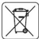
EneKtpnueckn 3axpaHbAHnte n3denn He Tp6Ba da ce n3XbbpTc DomauHNte OTnadu, a Tp6Ba da ce npedat 3a ONON3OTBOPRAHe B CbOTBeHTHe 3aBOi. HOpMaunra 3a ONON3OTBOPBAHeTo MoKe da 6bJe NOnyeha Ot npodabau Ha n3deJIeNo To MecTHNe Bnactn. HeroHDto eNektpnuecko n eJekTPoHHO o6OpyDaHe CbDbpxKa HenacNBn cy6ctanu 3a eCTeCTBeHaTa cpea. O6OpyDaHTo, HeOTdaJeHo 3a peuKnIpaHe, npedCTablaBa NotEHuaHa 3aannxa 3a OKonHaTa cpea n 3a 3dpabeTo Ha xopata.
- 3ana3Ba ce npaBOTO 3a n3BbPwBaHe Ha npomeHn.
Grupa Topex Spolka z ograniczona odpowiedzialnosci" Spolka komandytowa c6c ceaJIuSe BvB BapwaHa ul. Pograniczna 2/4 (HapuHaNo-HaTaBk: Grupa Topex") nHΦopMnpa, ye BCaKaBn ABTOPKn npaba Bbpxy CbIbPxHaHeTo Ha HAcToaTaNCTpyKUa (HapuHa No-HaTaBk: NHTpyKUa), BKIOuBaun Mekdy DpyrOTo HeHHra TeKT, NOMeCTeHNTE CHIMKN, CXEMN, YepTeKn, a CbIo Taka HeHInTe KOMNo3uIN, INpHaNDExaT N3KIOuHTeINHO Ha Grupa Topex n OndJeT ha npAbaHa 3aUnTa CbIaChO 3aKoHa ot 4 eBypapn 1994 roDHa 3a ABTopCKOTO npabo I cpoHNte My npaba (BIX KbPxABeH BeCTHNK 2006 N90 no3.631 cNo-HaTaBShInTe npomeH). KOnIPAHeTO, Bb3NPoN3BExKaDaHeTo, N6bIKyBaHeTo, MoiNfNpuAHeTo C KOMEpecka ue Ha LAnata NHTpyKUa, KaKTo n OTdEHNITE I elemEnT b63 CbIgacNeTo Ha Grupa Topex n3pa3eHo B NcMeHa φOpMa, e CTporo 3a6paHeHo n MOke da DoBeDe do PPNBnuaHeTo KbM rpaJdaHcKa n Haka3aTeInHa OTROBOPHOCT.
HR
PRIJEVOD ORIGINALNIH UPUTA
NAGIBNA PILA
59G812
POZOR: PRIJE POÇETKA KORISTENJA ALATA TREBA PAŽLJIVO PROÇITATI TE UPUTE I SPREMITI IH ZA DALNJE KORISTENJE
POSEBNI PROPISIO SIGURNOSTI
MJERE OPREZA:
OPSTE MERE BEZBEDNOSTI
SAVETI ZA BEZBEDNOST:
- Ne koristiti poce za secenje koje su ostecene ili deformisane.
- Promeniti ulozak na stolu, kada se iskoristi.
- Koristiti isključivo ploce za secenje koje preporučuje proizvodač, koje ispunjavaju zahtve norme EN 847-1.
-
Ne koristiti poce za secenje koje su napravljene od brzoreznog celika.
-
Koristiti sredstva za ličnu zašitu kao što su:
- stitnike za sluh, kakobise smanjio rizik od gubljenja sluha,
- zašitu za oči,
- zašitu za disajne puteve, kako bi se smanjio rizik prilikom isparavanja štetnih gasova,
- rukavice za rukovanje pločama za sećenje (ploče za sećenje treba držati za otvor kad god je to moguce) ili drugim grubim materijalima.
- Ukljuciti system za odvod praseine prilikom secenja drva.
BEZBEDAN RAD:
- Pre uključivanja testere svaki put treba proveravati strujni kabl, u slučaju oštećenja zameniti ga u ovlášćenom servisu.
- Pre ukljucivanja testere u struju, uvek treba proveriti da li napon mreze odgovara naponu koji je dat na nominalnoj tablici ureda.
- Osobama sa strane, a posebno deci, zabranjeno je da dodiruju uredaj ili strujni kabl, iijke im dozvoljen pristup do mesta na kome se radi.
- Potrebno je odabrati plocu za secenje prema vrsti materijala koji treba da se sce.
Zabranjeno je koristiti testeru za secenje materijala drugacijih od onih koje preporucije proizvoa.
Zabranjeno je koristiti testeru bez zašite ili kada je ona blokirana. - Potrebno je uveriti se da je rame dobro pričvršćeno za vreme sećenja ukoso.
- Podloga u okolini ureăja mora biti dobro odžavana i bez lakih materijala kao što su iverje i drugi OTPaci.
- Potrebno je obezbediti odgovarajuće svetlo, glavno ili lokalno.
- Radnik koji koristi uredaj mora biti odgovarajuće obrazovan u oblasti upotrebe i korišcenja uredaja.
- Koristiti iskljucivo ostre ploce za secenje, obratiti pažnju na maksimalnu brzinu oznaçenu na ploci za secenje.
- Uveriti se da upotrebljeni delovi kao i prstenovi vretena jesu odgovarajuce primenjeni, i u skaldu sa preporukama proizvoța.
- Ukoliko testera poseduje laser, primena drugacijeg tipa lasera ici dozvoljena. Popravku je potrebno da obavi proizvodač lasera ili ovlasceni predstavnik.
- Potrebno je uveriti se pre početka posla da li je urežaj pričvṛśćen za sto.
MERE BEZBEDNOSTIZA LASERSKI UREDAJ
Laserski uredaj koji se primenjuje u konstrukciji elektroureduja je klase 2 sa maksimalnom snagom <1mW , pri talasnoj duzini zračenja 650nm . Ovakav uredaj je šetan za vid, a isto tak zobranjeno je gledati direktno u pravcu izvora zračenja (preti opasnost od trenutnog slepila).
BETJENING OG VEDLIKEHOLD

LASERLAITTEEN TOIMINNAN TARKISTUS

AFVOEREN VAN HET STOF

COUPE AVEC DEPLACEMENT DU BRAS (DE LA TETE) DE LA SCIE A ONGLET

REEMPLACEMENT DES CHARBONS


- DETAILED SAFETY REGULATIONS
- PRECAUTIONS:
- SAFE OPERATION:
- SAFETY RULES FOR LASER DEVICE
- GRAPHITE
- Adjustments other than indicated in this instruction manual may expose you to laser radiation! CONSTRUCTION AND APPLICATION
- DESCRIPTION OF GRAPHIC PAGES
- DESCRIPTION OF USED GRAPHIC SIGNS
- EQUIPMENT AND ACCESSORIES
- PREPARATION FOR WORK
- HANDLING THE MITRE SAW
- INSTALLING THE MITRE SAW ON A WORKSHOP BENCH
- DUST EXTRACTION
- USING THE EXTENSION ARM (HEAD)
- VERTICAL CLAMP
- OPERATION/ADJUSTMENTS
- SWITCHING ON /SWITCHING OFF
- Switching ON
- Switching OFF
- OPERATION OF THE TABLE EXTENSIONS
- OPERATION OF THE CUTTING DEPTH LIMITER
- The cutting depth limiter can be used, when it is necessary to make a key in the workpiece. It is performed by making a surface cut in the workpiece, when the disc does not operate at full possible depth.
- SETTING THE WORKING TABLE FOR MITRE CUTTING
- CHECKING AND ADJUSTING THE PERPENDICULAR POSITION OF THE CUTTING DISC AND WORKING TABLE
- SETTING THE EXTENSION ARM (HEAD) FOR MITRE CUTTING
- LASER ADJUSTMENT
- STARTING THE SAW
- STOPPING THE SAW
- CUTTING WITH THE SAW
- CUTTING WITH THE MOVEMENT OF THE SAW EXTENSION ARM (HEAD) OF THE MITRE SAW
- CLEANING
- REPLACING THE CUTTING DISC
- REPLACING BATTERIES IN THE LASER UNIT
- REPLACING THE CARBON BRUSHES
- NOISE AND VIBRATION DATA
- ENVIRONMENTAL PROTECTION
- MEPbI IPEOCTOPOXHOCTN:
- BE3OPIACHARPABOTA:
- ПРABИАТEXHИКBE3ОПАСHОCTNПИРAPABOTEСЛA3EPHBIMYCTPOICTBOM
- HactpoikKa na3epa, BbIXOJaIa 3a paMKn OINcaHHoB DaAHHom pyKOBoIcTBe, UpeBaTa onaCHocTbIO na3epHoro 6bIyehnI!
- KOHCTPYKUNI INPIMMEHEHNE
- 3anpeaetc npimehrB 3neKtpoHCTpymEn He no Ha3HaueHIO!
- ONICAHNE K TPAQUeCKM N3OBPAXEHNAM
- PACUHΦPOBKA INPEUINPEXIAIOUX 3HAKOB
- OCHAUHNEI DONOLHNTBHBIE PNHAJEXKHOCTN
- IOnIroTOBKA K PABOTE
- NEPEMEUENIEIJIbI
- BKJIIOUeyHE/BbIKJIIOUeyHNE
- BkIoueHne
- BbiknIOueHne
- OBCLYKUBAHNE YJINHHTENEI CTOJA
- OBCLJXKUBAHNE OPGAHNUHTEJI TLYBUNHbI PACINILA
- IPOBEPKA PABOTbl JIA3EPA
- PERYJINPOBKA JIA3EPA
- BKJIIOUeyHNEIINbl
- OCTAHOBKA NINJIbI
- PABOTACIIIOI
- PACNJI C NEPEMELEHNEM ILEEA (ROJOBKNI) NJIbI
- OBCLYXUBAHNEI KOHCEBALM
- 甲CTKA
- 3AMEHA NIIbHORO DNCKA
- 3AMEHA BATAPEB JIA3EPHOM YCTPOICTBE
- HHOPMALUOBYPOBHE WUMANBUNPAUIN
- 3AUHTA OKPYXAIOUI CPEIbI
- MHΦOPMAUЯ OДATE N3ROTOBJIENY YKA3AHA B CEPNUHOM HOMEPE, KOTOPbI HAXOДNTcRA HA UN3DEJIIN
- UA
- IPEKJIAD OPNIHAJIbHOI IHCTPYKJI
- TOPUOBALbHA NIIJA
- DAOKJIADHI INPABUNA TEXHIKU BE3NEKN
- 3ACOBN B3NEKU:
- БЕЗЕКА ПALAЛ:
- INPABUNIATEXHIKINE3NEKNIIACKOPNUCTAHNJA3EPHUMIPNUCTPOEM
- 3AMIHA NJIbHORO DUCKY
- 3AMIHA ELEMENTTIB KINBLEHHRA JIA3EPHOMY MOyJI
- 3AMIHA BYIJIbHIX IITOK
- TEXHIYI NAPAMETPN
- INDEPARTAREA PRAFULUI
- MANIPULACE SVYSUVNYM RAMENEM (HLAVOU)
- IPEBOH A OPUNHANHATA HCHTPKU
- HACTOJEH LIPKUYIAPHEH TPOOH
- ПОДРОБИ ПРавиJA 3A BE3ОПАCHOCT
- PPEOXPAHNTEHMEPKN:
- BE3ONACHA PABOTA:
- ПРавиJA 3A BE3ONACHOCT HA JIA3EPHOTO YCTPOICTBO
- CTPYKTPA IN PPEH3HAUHNE
- ONICAHNE HA TPAΦNHTE CTPAHUN
- ONICAHNE HA N3NOJ3BAHNTE rPAQnHn CmBOLIN
- EKINNPOBKA N AKCECOAPN
- IODΓOTOBKA 3A PAδOTA
- IPEHACRHE HA TPOHOA
- MOHTAX HA ZUPKUYIAPHNY TPNOH KbM PABOTHATA MACA
- OTBEXDAHE HA INPAXA
- PABOTA C PAMOTO (JLABATA)
- BEPTUKAKJIHA CTYRA
- PABOTA/HACTPOIKNI
- BkIIOUBaHe
- N3KnIOuBaHe
- OBCLNYKBAHE HA YdblJXNTJEITE HA MACATA
- OBCLNYKBAHE HA ORPAHNUHTEJHA DJIbIOOHATA HA PRA3AHE
- HACTPOIKA HA PABOTHATA MACA 3A P83AHE IOd bIJI
- IPOBEPKA IN PEGYINPAHE HA IEPNEHINKUYIAPHATA HACTPOJKA HA PEXEUNI INCK CIPRAMO PABOTHATA MACA
- Ipn n3BbPwBaHTo Ha n3MepBaHnraTcneBa da ce y6eIM, ye n3MepBaTeHNrT ypei He ce doKocBa do 3b6a Ha peKeuMa dNCK, Tb' Kato npEeBnHa ne6eHHata Ha HknaKaTa OT MeTANOkepaMHn TBbpN cPiabn n3MepBaHTo MoKe da 6bDe HeTOUHO.
- IPOBEPKA I PEGYINPAHE HA INEPENHKUYARPHATA HACTPOKHA H PEXEUNA INCK CIPRAO OPGAHUHTEHATA JETBA.
- HACTPOIKA HA PAMOTO (TJABATA) 3A PRA3AHE CbC CKOBAHE
- IPOBEPKA HA PABOTATA HA JIA3EPA
- PEYUNPAHE HA JIA3EPA
- PnHaCtpoKaTaHa Na3epHnaIbUHe 6NbBa Da rneJaMe DnpeKTHO KbM Ia3epHna CHON Nm KbM HerOBOTOrNeDaHIO OTPaKeHne. Na3epHnO yCTpOcTBO cneDbA da Ce n3KlIOyBa, aKO Na3epbT He e uN3No3BaH.
- N3KJIIOUOBAHE HA TPOHOA
- PRAHECTPOHOHA
- PRAHE C INPEMECTBAHE HA PAMOTO (IJIABATA) HA TPNOHA
- OBCLNYXBAHEIIOIDIPbJKA
- NOCYNTBAHE
- CMRAHA HAPEXEUNI DNCK
- IOMRAHA HABATEPUNTEBJA3EPHNOyI
- CMHA HABbIePOdHnTEcETK
- TEXHNUECKN NAPAMETPN
- HOMHANHDAHHN
- DAHHN 3A WUMAN BUNPAUNITE
- ONA3BAHE HA OKOJIHATA CPEDA
- HR
- PRIJEVOD ORIGINALNIH UPUTA
- NAGIBNA PILA
- POSEBNI PROPISIO SIGURNOSTI
- MJERE OPREZA:
- OPSTE MERE BEZBEDNOSTI
- SAVETI ZA BEZBEDNOST:
- BEZBEDAN RAD:
- MERE BEZBEDNOSTIZA LASERSKI UREDAJ
- BETJENING OG VEDLIKEHOLD
- LASERLAITTEEN TOIMINNAN TARKISTUS
- AFVOEREN VAN HET STOF
- COUPE AVEC DEPLACEMENT DU BRAS (DE LA TETE) DE LA SCIE A ONGLET
- REEMPLACEMENT DES CHARBONS
Brand : Graphite
Model : 59G812
Category : Saw