
LBP8000E - Blower EGO - Free user manual and instructions
Find the device manual for free LBP8000E EGO in PDF.
| Product type | Cordless backpack blower |
| Brand | EGO |
| Model | LBP8000E |
| Voltage | 56 V |
| Maximum air flow | 1360 m³/h |
| Maximum air velocity | 85 m/s |
| Maximum blowing force | 26 N |
| Weight (without battery, with tube) | 7.4 kg |
| Sound power level | 97 dB(A) |
| Sound pressure level (at ears) | 86.2 dB(A) |
| Vibrations | 0.4 m/s² |
| Operating temperature | -15°C to 40°C |
| Storage temperature | -20°C to 70°C |
| Protection | IPX5 |
| Power supply | 56 V lithium-ion battery (2 slots) |
| Main functions | Turbo, speed regulator, LCD screen |
| Package contents | Blower, blower tube, conical nozzle, harness, manual |
| Maintenance | Clean air inlets, remove batteries |
| Safety | Wear goggles and hearing protection, keep 15 m away from people |
| Warranty | Visit egopowerplus.com |
Frequently Asked Questions - LBP8000E EGO
User questions about LBP8000E EGO
0 question about this device. Answer the ones you know or ask your own.
Ask a new question about this device
Download the instructions for your Blower in PDF format for free! Find your manual LBP8000E - EGO and take your electronic device back in hand. On this page are published all the documents necessary for the use of your device. LBP8000E by EGO.
USER MANUAL LBP8000E EGO
LBP8000E
56 VOLT LITHIUM-ION
natural_image
Technical line drawing of a battery pack with internal circuitry (no text or symbols)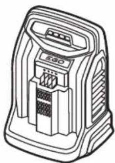
natural_image
Line drawing of a portable electronic device with ventilation slots and a control panel (no text or symbols)CH5500E, CH2100E, CH3200E, CH7000E
natural_image
Technical line drawing of a mechanical component with two symmetrical parts and directional arrows indicating flow or movement (no text or symbols)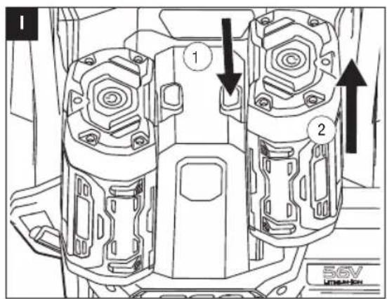
natural_image
Illustration of a person adjusting a belt buckle, showing hands and arrows indicating movement (no text or symbols)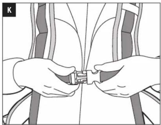
natural_image
Illustration of two hands adjusting a small object on a white background (no text or symbols)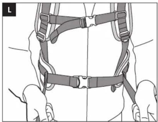
natural_image
Line drawing of a person wearing a full-body harness and belt (no text or symbols)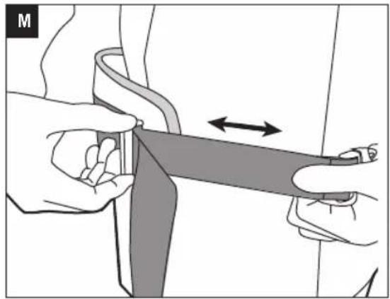
natural_image
Illustration of hands holding a belt buckle with an arrow indicating compression (no text or symbols)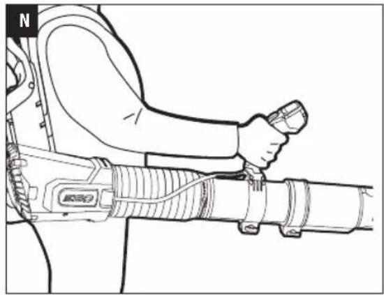
natural_image
Line drawing of a person using a handheld device to interact with a mechanical device (no text or symbols visible)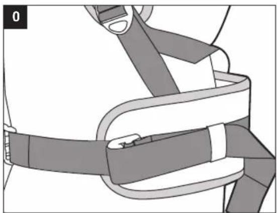
natural_image
Illustration of a person wearing a high-visibility belt and harness (no text or symbols)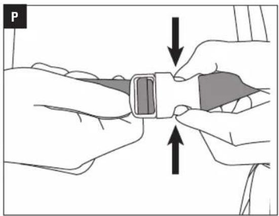
natural_image
Illustration of hands adjusting a white belt buckle with arrows indicating compression or adjustment (no text or symbols)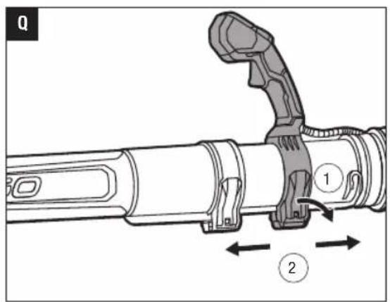
natural_image
Illustration of a hand holding a tool with a magnified inset showing movement or positioning (no text or symbols)
natural_image
Line drawing of a person adjusting a mechanical device with a hand holding the tool (no text or symbols present)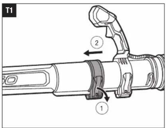
natural_image
Technical line drawing of a mechanical device with attached cable and adjustment lever (no text or symbols)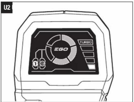
U4

natural_image
Technical line drawing of a mechanical assembly (no text or symbols visible)READ ALL INSTRUCTIONS!
EN

READ OPERATOR'S MANUAL
NOTICE: These instructions shall also be available in an alternative format, e.g. on a website.
⚠️ Residual risk! People with electronic devices, such as pacemakers, should consult their physician(s) before using this product. Operation of electrical equipment in close proximity to a heart pacemaker could cause interference or failure of the pacemaker.
WARNING: To ensure safety and reliability, all repairs and replacements should be performed by a qualified service technician.
SAFETY SYMBOLS
The purpose of safety symbols is to attract your attention to possible dangers. The safety symbols and the explanations with them deserve your careful attention and understanding. The symbol warnings do not, by themselves, eliminate any danger. The instructions and warnings they give are no substitutes for proper accident prevention measures.
WARNING: Be sure to read and understand all safety instructions in this Operator's Manual, including all safety alert symbols such as "DANGER," "WARNING," and "CAUTION" before using this tool. Failure to following all instructions listed below may result in electric shock, fire, and/or serious personal injury.
DAMAGE PREVENTION AND INFORMATION MESSAGES
These inform the user of important information and/or instructions that could lead to equipment or other property damage if they are not followed. Each message is preceded by the word "NOTICE", as in the example below:
NOTICE: Equipment and/or property damage may result if these instructions are not followed.

WARNING: The operation of any power tools can result in foreign objects being thrown into your eyes, which can result in severe eye damage. Before beginning power tool operation, always wear safety goggles or safety glasses with side shields and a full face shield when needed. We recommend a Wide Vision Safety Mask for use over eyeglasses or standard safety glasses with side shields.
EN SAFETY INSTRUCTIONS
This page depicts and describes safety symbols that may appear on this product. Read, understand, and follow all instructions on the machine before attempting to assemble and operate.

Safety Alert

Always wear safety goggles or safety glasses with side shields and a full face shield when operating this product.

Always wear ear protection when operating this product.

To reduce the risk of injury, user must read operator's manual before using this product.
Keep all bystanders at least 15m away.

This product is in accordance with applicable EC directives.

This product is in accordance with applicable UK legislation.

Waste electrical products should not be disposed of with household waste. Take to an authorized recycler.
V Volt A Amperes
Hz Hertz W Watt
min Minutes m
km/h Kilometers Per Hour
n_0 No Load Speed
^3/h Cubic Meter Per Hour

Direct Current
... /min Per Minute
IPX5 Protection From Water Jets
SPECIFICATIONS
| Voltage | 56 V |
| Maximum Air Volume 1360 m | ^3/h |
| Maximum Air Velocity 85 m/s | |
| Maximum Blower Force 26 N | |
| Recommended Operating Temperature | -15°C-40°C |
| Recommended Storage Temperature | -20°C-70°C |
| Blower Weight (Without battery with tube) | 7.4 kg |
| Measured sound power level L_WA | 97 dB(A)K=1.2 dB(A) |
| Sound pressure level at operator's ear L_PA | 86.2 dB(A)K=2.5 dB(A) |
| Guaranteed sound power level L_WA (according to 2000/14/EC) | 98 dB(A) |
| Vibration a_h | 0.4 m/ s^2 K=1.5 m/ s^2 |
■ The declared vibration total value has been measured in accordance with a standard test method and may be used for comparing one tool with another;
■ The declared vibration total value may also be used in a preliminary assessment of exposure.
NOTICE: The vibration emission during actual use of the power tool can differ from the declared value in which the tool is used; In order to protect the operator, user should wear gloves and ear protectors in the actual conditions of use.
PACKING LIST (FIG. A1)
DESCRIPTION
KNOW YOUR BLOWER (Fig. A1 & A2)
- Handle
- Battery-Release Buttons
- Latch
- Electric Contacts
- Assist Handle
- Air Inlet
-
Bellows
-
Control-handle Tube
- Blower Tube
- Control Handle
- Backpack Plate
- Blower-tube Storage Knob
- Adjustable Support Harness
- Tapered Nozzle
- Cruise Control Button
- LCD Screen
- Turbo Button
- Trigger Switch
- Tube-hanging Groove
- Quick-release Lever
- Fuel Gauge
- Fan Icon
- Turbo Indicator
- Air-speed Indicator
- Cruise Control Icon
- Battery Icon
WARNING: The safe use of this product requires an understanding of the information on the tool and in this instruction manual as well as knowledge of the project you are attempting. Before use of this product, familiarize yourself with all operating features and safety rules.
ASSEMBLY
WARNING: If any parts are damaged or missing, do not operate this product until the parts are replaced. Use of this product with damaged or missing parts could result in serious personal injury.
WARNING: Do not attempt to modify this product or create accessories not recommended for use with this blower. Any such alteration or modification is misuse and could result in a hazardous condition leading to possible serious personal injury.
WARNING: To prevent accidental starting that could cause serious personal injury, always remove the batteries from the tool when assembling parts.
ASSEMBLING THE BLOWER TUBES
Connecting the Control-handle Tube Assembly to the Bellows (Fig. C)
- Insert the upper end of the control-handle tube into the bellows as far as it will go.
EN
- Fully tighten the screw in the clamping collar on the bellows.
| C-1 Clamping Collar |
| C-2 Screw |
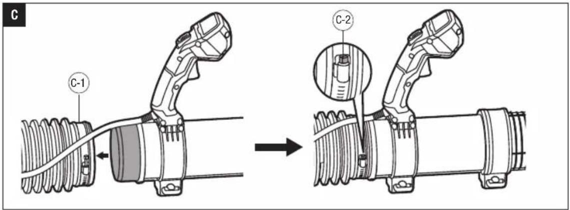
Connecting the Blower Tube to the Control-handle Tube (Fig. D)
- Loosen and remove the quick-release lever and wing nut from the tube clamp assembly fixed on the blower tube.
| D-1 | Tube Clamp |
| D-2 | Wing Nut |
- Align the groove in the blower tube with the rib on the control-handle tube, slide the blower tube over the control-handle tube as far as it will go.
- Insert the pin of the quick-release lever and close the lever onto the tube clamp.
- Tighten the wing nut to secure the tube clamp in place.
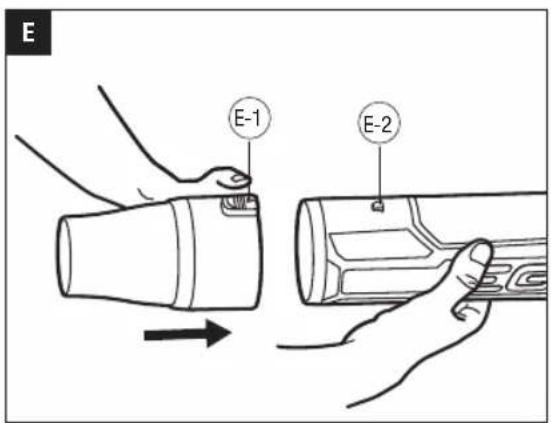
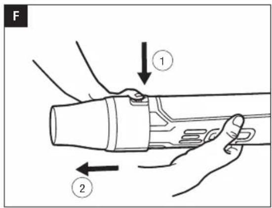
Connecting the Tapered Nozzle to the Blower Tube (Fig. E, F)
- Align the groove in the nozzle with the latch on the tube. Push the nozzle over the tube until it securely snaps into place.
- To remove the nozzle, press and hold the nozzle-release button to disengage the latch, then pull the nozzle straight away from the blower tube.
| E-1 | Nozzle-release Button |
| E-2 | Latch |
OPERATION
WARNING: Do not allow familiarity with this product to make you careless. Remember that a careless fraction of a second is sufficient to inflict serious injury.
WARNING: Do not use any attachments or accessories not recommended by the manufacturer of this product. The use of attachments or accessories not recommended can result in serious personal injury.
WARNING: Always remove the batteries from the product when you are assembling parts, making adjustments, cleaning, or when not in use. Removing the batteries will prevent accidental starting that could cause serious personal injury.
Before each use, inspect the entire product for damaged,
missing, or loose parts, such as screws, nuts, bolts, caps, etc. Tighten securely all fasteners and caps and do not operate this product until all missing or damaged parts are replaced.
WARNING: If you encounter an emergency, separate the chest buckle straightly to take off the blower.
APPLICATION
You may use this product for the purposes listed below:
■ Clearing hard surfaces such as driveways and walkways.
- Keeping decks and driveways free from leaves and pine needles.
NOTICE: The tool is to be used only for its prescribed purpose. Any other use is deemed to be a case of misuse.
INSTALLING/REMOVING THE BATTERIES
CHARGE BEFORE FIRST USE.
Use only with batteries and chargers listed fig.B.
NOTICE: For best performance, we recommend use of any EGO 56V battery with a capacity higher than 5.0 Ah.
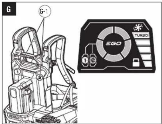
The blower has two active battery compartments on the left and right side of the battery compartment housing.
NOTE: The blower can operate with one or two batteries. Using two batteries gives you a longer run time and efficient power draw managed by PEAK POWER™ technology.
If a battery has been inserted into battery compartment marked with 1 or 2 on the backpack plate, the corresponding battery icon illuminates on the LCD screen (Fig. G) after you turn on the blower.
G-1 Battery Compartment Position Mark
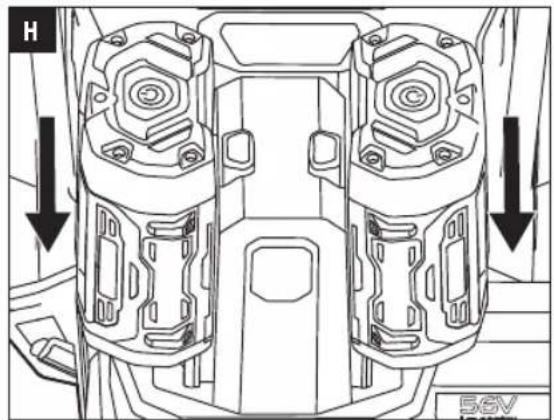
■ To Install (Fig. H)
Align the battery ribs with the mounting slots and press the battery down until you hear a "click". Repeat the process to install the second battery.
■ To Remove (Fig. I)
Depress the battery-release buttons and pull the batteries out.
WARNING: Always take care to note the location of your feet, children, or pets when pressing the battery-release button. Serious injury could result if the battery falls. NEVER remove the battery when in a high location.
WARNING: Dress properly to reduce the risk of injury when operating this tool. Do not wear loose clothing
or jewelry. Wear eye and ear/hearing protection. Wear heavy, long pants, boots and gloves. Do not wear short pants or sandals or go barefoot.
To Adjust The Support Harness
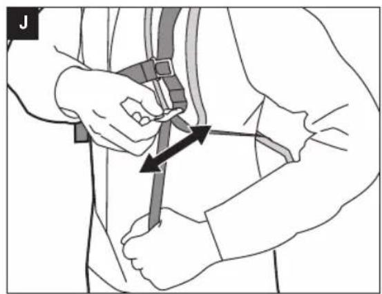
- Put your arms through the shoulder straps to support the blower on your back.
- Adjust both shoulder straps until you feel comfortable with the blower on your back (Fig. J).
- Snap the chest buckle and adjust its length if necessary (Fig. K).
- Snap the waist buckle and adjust its length so that the backpack is securely supported by your hips (Fig. L & M).
- Readjust the shoulder straps for security and comfort. Makes sure that the backpack sits securely on your back, with the weight supported by the waist strap, and without excess movement when you move (Fig. N).
- Insert any extra length of belt around the waist into the elastic on both sides (Fig. 0).
- To detach the tool from your back, just press the waist and chest buckles to release them (Fig. P).
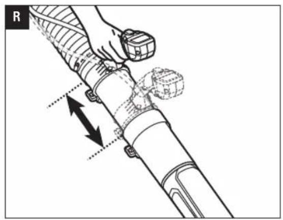
To Adjust the Control Handle
- Release the quick-release lever to move the control handle forward or backward as needed (Fig. Q & R) and then engage the quick-release lever to secure the handle in place.
- You may also rotate the handle as needed for comfort (Fig. S).
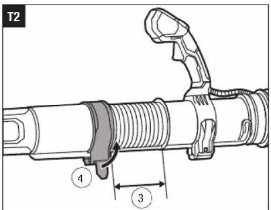
To Adjust the Control-handle Tube Length (Fig. T1, T2)
- Release the quick-release lever to move the blower tube to a comfortable operating position.
- Engage the quick-release lever to secure the blower tube in place
STARTING/STOPPING THE BLOWER
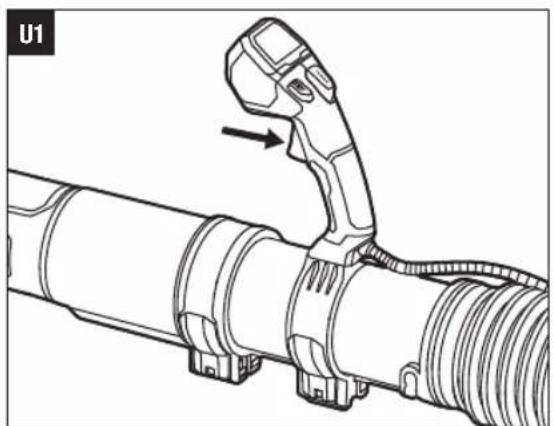
Trigger Switch (Fig. U1, U2)
■ Depress the trigger switch to turn on the blower. The LCD screen displays the fuel gauge, battery icon, air speed indicator.
■ The air speed of the blower is controlled with the trigger switch. The further the trigger switch is depressed, the more air flows out of the nozzle. Adjust the speed to suit the task at hand. The corresponding air speed icon displays on the LCD screen.
■ Release the trigger to turn off the blower. After 6 seconds the LCD screen turns off.
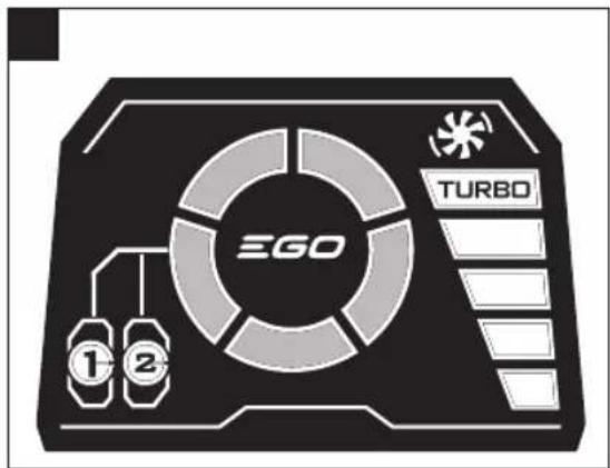
Turbo Mode
With the trigger depressed and held, press the turbo button to maximize the airflow (Fig. U1). The turbo indicator and the fan icon illuminates on the LCD screen (Fig. U3).
NOTE: The blower returns to the previous speed when the turbo button is released.
Cruise Control Model
The cruise control mode offers operations without trigger switch.
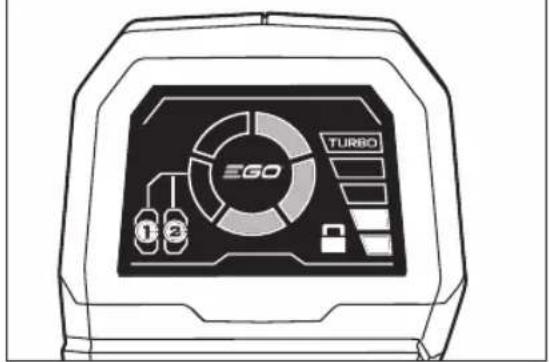
To engage the cruise control mode:
- Depress and hold the trigger switch at the desired speed (Fig. U1).
- Press the cruise control button. Release the button after the cruise control icon appears on the LCD screen (Fig. U4).
- Release the trigger switch, the blower keeps running. Press the turbo button under cruise control mode can temporarily increase the air speed to the maximum level. The blower resumes the previous speed when the turbo button is released.
To disengage the cruise control mode:
Press the cruise control button again to disengage the cruise control mode. The cruise control icon on the LCD screen disappears.
Tips For Using The Blower
■ Use rakes and brooms to loosen debris before blowing. In dusty conditions, slightly dampen surfaces if water is available.
■ Watch out for children, pets, open windows, or freshly washed cars, and blow debris safely away.
■ After using blowers or other equipment, clean up!
MAINTENANCE
WARNING: When servicing, use only identical replacement parts. Use of any other parts may create a hazard or cause product damage. To ensure safety and reliability, all repairs should be performed by a qualified service technician.
WARNING: To avoid serious personal injury, always remove the battery from the product when cleaning or performing any maintenance.
GENERAL MAINTENANCE
Avoid using solvents when cleaning plastic parts. Most plastics are susceptible to damage from various types of
EN
commercial solvents and may be damaged by their use. Use clean cloths to remove dirt, dust, oil, grease, etc.
WARNING: Do not at any time let brake fluids, petrol, petroleum-based products, penetrating oils, etc., come in contact with plastic parts. Chemicals can damage, weaken or destroy plastic which may result in serious personal injury.
STORAGE
■ Remove the battery from the blower.
■ Clean all foreign material from the air inlets of the blower.
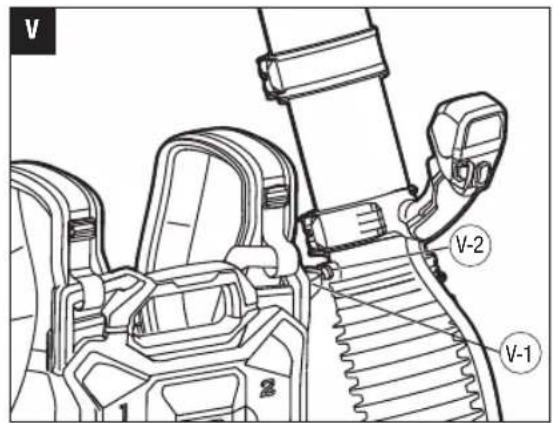
■ Align the blower-tube storage knob with the tube-hanging groove and hook the blower tube onto the battery compartment housing (Fig. V & W).
■ Store in an enclosed space that is inaccessible to children. Keep away from corrosive agents, such as garden chemicals and de-icing salts.
| V-1 Blower-Tube Storage Knob |
| V-2 Tube-Hanging Groove |
Protecting the environment
Do not dispose of electrical equipment, used battery and charger into household waste!
Take this product to an authorized recycler and make it available for separate collection. Electric tools must be returned to an environmentally compatible recycling facility.
TROUBLESHOOTING
| PROBLEM CAUSE SOLUTION | ||
| Blower doesn't work. | No electrical contact between the blower and batteries.The batteries are depleted.The batteries or blower is too hot. | Remove battery, check contacts and reinsert the battery.Charge the batteries.Cool the batteries and blower until the temperature drops below 67°C. |
| The air velocity decreases significantly. | The air inlet is blocked by debris.Excessive wearing of motor fan. | Remove the batteries, clear the debris.Contact EGO service center for repair. |
| LCD Screen Fault. | LCD assembly is broken or bad wire connection of the LCD assembly. | Contact EGO service center for repair. |
EN
WARRANTY
EGO WARRANTY POLICY
Please visit the website egopowerplus.com for full terms and conditions of the EGO Warranty policy.
LISTA DE PEÇAS (IMAGEM A1)
DESCRIÇÃO
GENERELT VEDLIKEHOLD
POLITYKA GWARANCYJNA EGO
CITIȚI MANUALUL DE INSTRUCTIUNI
LUGEGE KASUTUSJUHENDIT
g_1g_2s_3o_0 m b s_4m_4 m o_u l_5b_4m_4 d_4z_3s_5g_4m_4
zsgmbomogds: gl oblu6gj3gdo slg3g bgmdahs3qmdos semgmbs8oqcm gmbds8do, da gsmomso 398396q8g.
3d/lo 30mmdg6no lssando
s3g0g0g0g0g0g0g0g0g0g0g0g0g0g0g0g0g0g0g0g0g0g0g0g0g0g0g0g0g0g0g0g0g0g0g0g0g0g0g0g0g0g0g0g0g0g0g0g0g0g0g
lsāgāngzqmsb sājī mǎo sājāngyǎn sāyāngyānsāgāmǎn lùdān sāsāxīgbs qas dāsāgbybs dāsāngl sāyāngyānsāgāmǎn dāmāsāgbybs dāyāgjān.
gsgfbomogds: lssgh2gmsd agodmgds odgdsol gmo sb mbo szgdeqmsgmbon. mbo szgdeqmsgmbol qsdmgbdgs qsdmzom qmbol ngfim bsbgndcmzo qsdmgbdolongol, bmdgmlbs gfbngb3gmymgl PEAK POWER™ ggbmcmgos.
g_2g_1g_2m_6g_0 s_3g_1g_2m_5g_3m_6 l_5s_3s_2s_4s_5 d_0 g_1g_0 g_0m_6g_1 g_5 g_5s_3s_4s_5 g_0 s_3g_1g_2m_5g_3m_6
natural_image
Technical line drawing of a portable air pusher with attached boom, showing internal components and no text or symbols.LBP8000E
56 96


- LBP8000E
- VOLT LITHIUM-ION
- READ ALL INSTRUCTIONS!
- READ OPERATOR'S MANUAL
- SAFETY SYMBOLS
- DAMAGE PREVENTION AND INFORMATION MESSAGES
- EN SAFETY INSTRUCTIONS
- PACKING LIST (FIG. A1)
- DESCRIPTION
- KNOW YOUR BLOWER (Fig. A1 & A2)
- ASSEMBLY
- ASSEMBLING THE BLOWER TUBES
- Connecting the Control-handle Tube Assembly to the Bellows (Fig. C)
- EN
- Connecting the Blower Tube to the Control-handle Tube (Fig. D)
- Connecting the Tapered Nozzle to the Blower Tube (Fig. E, F)
- OPERATION
- APPLICATION
- INSTALLING/REMOVING THE BATTERIES
- CHARGE BEFORE FIRST USE.
- To Adjust The Support Harness
- To Adjust the Control Handle
- To Adjust the Control-handle Tube Length (Fig. T1, T2)
- STARTING/STOPPING THE BLOWER
- Trigger Switch (Fig. U1, U2)
- Turbo Mode
- Cruise Control Model
- To engage the cruise control mode:
- To disengage the cruise control mode:
- Tips For Using The Blower
- MAINTENANCE
- GENERAL MAINTENANCE
- STORAGE
- Protecting the environment
- WARRANTY
- EGO WARRANTY POLICY
- LISTA DE PEÇAS (IMAGEM A1)
- DESCRIÇÃO
- GENERELT VEDLIKEHOLD
- POLITYKA GWARANCYJNA EGO
- CITIȚI MANUALUL DE INSTRUCTIUNI
- LUGEGE KASUTUSJUHENDIT
Brand : EGO
Model : LBP8000E
Category : Blower