USER MANUAL RTBS18X RYOBI
natural_image
Close-up of a black hard drive with a control panel and display unit against a striped patterned background (no visible text or symbols)
text_image
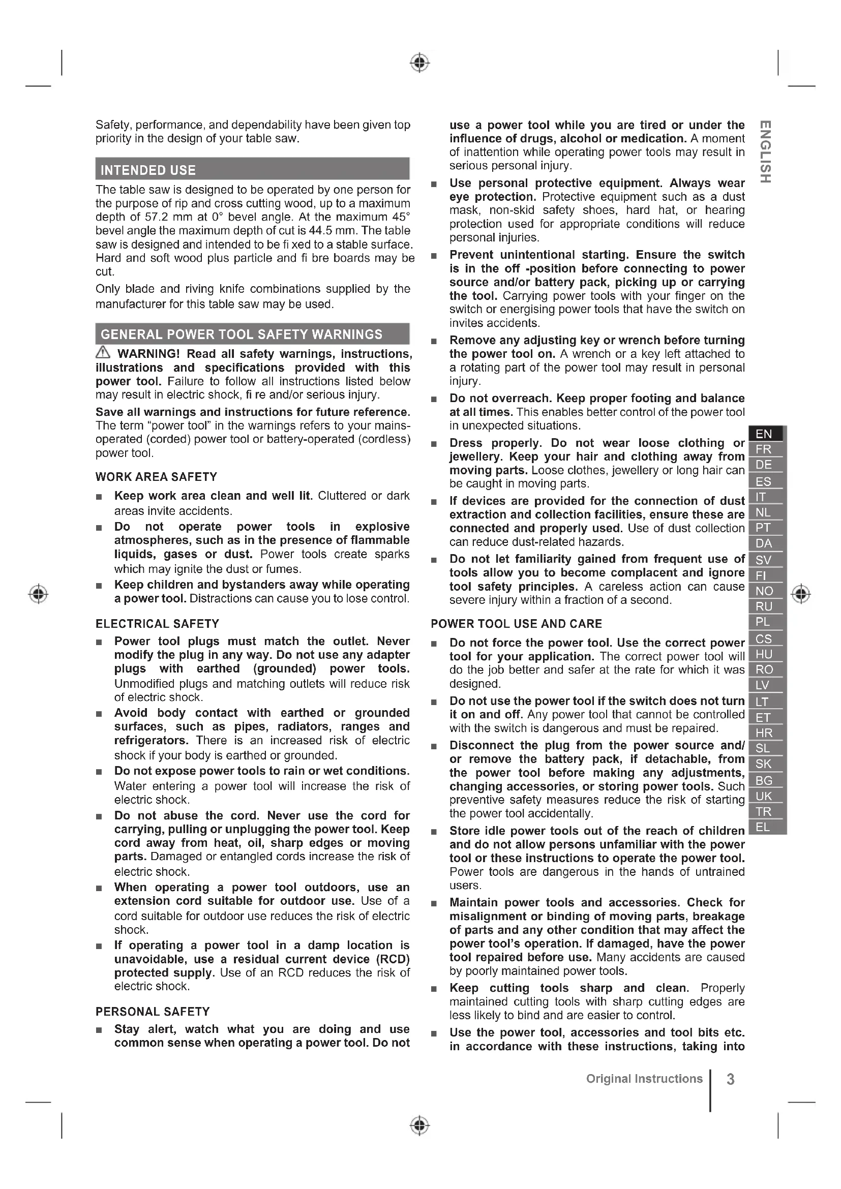
RYOBI
ONE HP
ø210
mm

natural_image
Close-up of a mechanical clamp or bracket assembly with black and white components (no visible text or symbols)
EN
FR
DE
ES
IT
NL
PT
DA
SV
FI
NO
RU
PL
CS
HU
RO
LV
LT
ET
HR
SL
SK
BG
UK
TR
EL
RTBS18X

| Important! | It is essential that you read the instructions in this manual before assembling, maintaining and operating the product. |
| Attention! | Il est essentiel que vous lisiez les instructions contenues dans ce manuel avant d'assembler, d'entretenir et d'utiliser le produit. |
| Achtung! | Es ist wichtig, dass Sie vor Zusammenbau, Wartung und Benutzung des Produktes die Anweisungen in dieser Anleitung lesen. |
| ¡Atención! | Resulta fundamental que lea este manual de instrucciones antes de realizar el montaje, el mantenimiento y de utilizar este producto |
| Attenzione! | E’ importante leggere le istruzioni contenute nel presente manuale prima di montare il prodotto, svolgere le operazioni di manutenzione sullo stesso e metterlo in funzione. |
| Let op! | Het is van essentieel belang dat u de instructies in deze gebruiksaanwijzing leest voor u het product monteert, onderhoudt en gebruikt. |
| Atenção! | É fundamental que leia as instruções deste manual antes da montagem, manutenção e operação do aparelho. |
| OBS! | Det er vigtigt, at man læser instrukserne i denne brugsanvisning, inden man samler, vedligeholder og betjener produktet. |
| Observera! | Det är viktigt att du läser instruktionerna i manualen före montering, användning och underhåll av produkten. |
| Huomio! | On tärkeää, että luet tämän käsikirjan ohjeet ennen tuotteen kokoamista, huoltoa ja käyttöä. |
| Advarsel! | Det er viktig at du leser instruksjonene i denne manualen før sammensetning, vedlikehold og bruk av produktet |
| Внимание! | Необходимо прочитать инструкции в данном руководстве перед сборкой, обслуживанием и эксплуатацией этого изделия. |
| Uwaga! | Koniecznie należy przeczytać instrukcje zawarte w tym podręczniku przed montażem, obsługą oraz konserwacją produktu. |
| Dûležité upozornění! | Neinstalujte, neprovádějte údržbu ani nepoužívejte tento výrobek dříve, než si přečtete pokyny uvedené v tomto návodu. |
| Figyelem! | Fontos, hogy a termék összeszerelése, karbantartása és használata előtt elolvassa a kézikönyvben található utasításokat. |
| Atenție! | Este esențial să citiți instrucțiunile din acest manual înainte de asamblare, efectuarea întreținerii și operarea produsului. |
| Uzmanību! | Ir svarīgi izlasīt šīs rokasgrāmatas instrukcijas pirms uzstādīšanas, apkopes un preces darbināšanas. |
| Dèmesio! | Prieš surenkant, prižiūrint ir naudojant gaminį, būtina perskaityti šiame vadove pateiktus nurodymus. |
| Tähtis! | Enne masina kokkupanekut, hooldamist ja kasutama hakkamist tuleb käesolevas juhendis esitatud juhised kindlasti läbi lugeda. |
| Upozorenje! | Vrlo je važno da ste prije sklapanja, održavanja i rada s ovim proizvodom pročitali upute u ovom priručniku. |
| Pomembno! | Pomembno je da pred montażo vzdrževanjem in uporabo tega izdelka preberete navodila v tem priročniku. |
| Upzornenie! | Je dôležité, aby ste si pred montážou, údržbou a obsluhou produktu prečitali pokyny v tomto návode. |
| Важно! | Изключително важно е да прочетете инструкциите в настоящото ръководство, преди да преминете към сглобяване, поддръжка или работа с продукта. |
| Важливо! | Дуже важливо, щоб ви прочитали інструкції в цьому керівництві перед складанням, обслуговуванням та експлуатацією цієї машини. |
| Dikkat! | Ürünün montajini, bakımını yapmadan ve ürünü çalıştırmadan önce bu kılavuzda yer alan talimatları okumanız önemlidir. |
| Проσοχή! | Еівали полú σημαντικό να διαβάσετε τις οδηγίες στο παρόν εγχειρίδιο πριν συναρμολογήσετε, συντηρήσετε ή λειτουργήσετε το προϊόν. |
Subject to technical modification | Sous réserve de modifications techniques | Technische Änderungen vorbehalten | Bajo reservade modificaciones técnicas | Con riservadi eventuali modifiche tecniche | Technischewijzigingen voorbehouden | Com reserva de modificações técnicas | Med forbehold for tekniske ændringer | Med förbehåll för tekniska ändringar | Tekniset muutokset varataan | Med forbehold om tekniske endringer | могут быть внесены технические изменения | Z zastrzeżeniem modyfikacji technicznych | Změny technických údajů vyhrazeny | A můszaki módosítás jogát fenntartjuk | Sub rezerva modificațiilor tehnice | Paturam tiesības mainīt tehniskos raksturlielumus | Pasiliekant teisę daryti techninius pakeitimus | Tehnilised muudatused võimalikud | Podloæno tehniëkim promjenama | Tehnične spremembe dopuščene | Prävo na technické zmeny je vyhradenė | Подлежи на технически модификации | Є об'єктом для технічних змін | Teknik değişiklik hakkı saklıdır | Утю тнү епіфúлаξη техвікών тропотпоїσεων
Safety, performance, and dependability have been given top priority in the design of your table saw.
INTENDED USE
The table saw is designed to be operated by one person for the purpose of rip and cross cutting wood, up to a maximum depth of 57.2 mm at 0° bevel angle. At the maximum 45° bevel angle the maximum depth of cut is 44.5 mm. The table saw is designed and intended to be fixed to a stable surface. Hard and soft wood plus particle and fibre boards may be cut.
Only blade and riving knife combinations supplied by the manufacturer for this table saw may be used.
⚠ WARNING! Read all safety warnings, instructions, illustrations and specifications provided with this power tool. Failure to follow all instructions listed below may result in electric shock, fi re and/or serious injury.
Save all warnings and instructions for future reference. The term “power tool” in the warnings refers to your mains-operated (corded) power tool or battery-operated (cordless) power tool.
WORK AREA SAFETY
- Keep work area clean and well lit. Cluttered or dark areas invite accidents.
- Do not operate power tools in explosive atmospheres, such as in the presence of flammable liquids, gases or dust. Power tools create sparks which may ignite the dust or fumes.
- Keep children and bystanders away while operating a power tool. Distractions can cause you to lose control.
ELECTRICAL SAFETY
■ Power tool plugs must match the outlet. Never modify the plug in any way. Do not use any adapter plugs with earthed (grounded) power tools. Unmodified plugs and matching outlets will reduce risk of electric shock.
- Avoid body contact with earthed or grounded surfaces, such as pipes, radiators, ranges and refrigerators. There is an increased risk of electric shock if your body is earthed or grounded.
- Do not expose power tools to rain or wet conditions. Water entering a power tool will increase the risk of electric shock.
- Do not abuse the cord. Never use the cord for carrying, pulling or unplugging the power tool. Keep cord away from heat, oil, sharp edges or moving parts. Damaged or entangled cords increase the risk of electric shock.
- When operating a power tool outdoors, use an extension cord suitable for outdoor use. Use of a cord suitable for outdoor use reduces the risk of electric shock.
If operating a power tool in a damp location is unavoidable, use a residual current device (RCD) protected supply. Use of an RCD reduces the risk of electric shock.
PERSONAL SAFETY
■ Stay alert, watch what you are doing and use common sense when operating a power tool. Do not
use a power tool while you are tired or under the influence of drugs, alcohol or medication. A moment of inattention while operating power tools may result in serious personal injury.
■ Use personal protective equipment. Always wear eye protection. Protective equipment such as a dust mask, non-skid safety shoes, hard hat, or hearing protection used for appropriate conditions will reduce personal injuries.
■ Prevent unintentional starting. Ensure the switch is in the off -position before connecting to power source and/or battery pack, picking up or carrying the tool. Carrying power tools with your finger on the switch or energising power tools that have the switch on invites accidents.
■ Remove any adjusting key or wrench before turning the power tool on. A wrench or a key left attached to a rotating part of the power tool may result in personal injury.
- Do not overreach. Keep proper footing and balance at all times. This enables better control of the power tool in unexpected situations.
■ Dress properly. Do not wear loose clothing or jewellery. Keep your hair and clothing away from moving parts. Loose clothes, jewellery or long hair can be caught in moving parts.
If devices are provided for the connection of dust extraction and collection facilities, ensure these are connected and properly used. Use of dust collection can reduce dust-related hazards.
- Do not let familiarity gained from frequent use of tools allow you to become complacent and ignore tool safety principles. A careless action can cause severe injury within a fraction of a second.
- Do not force the power tool. Use the correct power tool for your application. The correct power tool will do the job better and safer at the rate for which it was designed.
- Do not use the power tool if the switch does not turn it on and off. Any power tool that cannot be controlled with the switch is dangerous and must be repaired.
- Disconnect the plug from the power source and/or remove the battery pack, if detachable, from the power tool before making any adjustments, changing accessories, or storing power tools. Such preventive safety measures reduce the risk of starting the power tool accidentally.
■ Store idle power tools out of the reach of children and do not allow persons unfamiliar with the power tool or these instructions to operate the power tool. Power tools are dangerous in the hands of untrained users.
- Maintain power tools and accessories. Check for misalignment or binding of moving parts, breakage of parts and any other condition that may affect the power tool's operation. If damaged, have the power tool repaired before use. Many accidents are caused by poorly maintained power tools.
- Keep cutting tools sharp and clean. Properly maintained cutting tools with sharp cutting edges are less likely to bind and are easier to control.
■ Use the power tool, accessories and tool bits etc. in accordance with these instructions, taking into
account the working conditions and the work to be performed. Use of the power tool for operations different from those intended could result in a hazardous situation.
- Keep handles and grasping surfaces dry, clean and free from oil and grease. Slippery handles and grasping surfaces do not allow for safe handling and control of the tool in unexpected situations.
■ Recharge only with the charger specified by the manufacturer. A charger that is suitable for one type of battery pack may create a risk of fire when used with another battery pack.
■ Use power tools only with specifically designated battery packs. Use of any other battery packs may create a risk of injury and fire.
- When battery pack is not in use, keep it away from other metal objects, like paper clips, coins, keys, nails, screws or other small metal objects, that can make a connection from one terminal to another. Shorting the battery terminals together may cause burns or a fire.
■ Under abusive conditions, liquid may be ejected from the battery; avoid contact. If contact accidentally occurs, flush with water. If liquid contacts eyes, additionally seek medical help. Liquid ejected from the battery may cause irritation or burns.
- Do not use a battery pack or tool that is damaged or modified. Damaged or modified batteries may exhibit unpredictable behaviour resulting in fire, explosion or risk of injury.
- Do not expose a battery pack or tool to fire or excessive temperature. Exposure to fire or temperature above 130°C may cause explosion.
■ Follow all charging instructions and do not charge the battery pack or tool outside the temperature range specified in the instructions. Charging improperly or at temperatures outside the specified range may damage the battery and increase the risk of fire.
SERVICE
■ Have your power tool serviced by a qualified repair person using only identical replacement parts. This will ensure that the safety of the power tool is maintained.
■ Never service damaged battery packs. Service of battery packs should only be performed by the manufacturer or authorized service providers.
SAFETY INSTRUCTIONS FOR TABLE SAWS
- Keep guards in place. Guards must be in working order and be properly mounted. A guard that is loose, damaged, or is not functioning correctly must be repaired or replaced.
■ Always use saw blade guard, riving knife and anti-kickback pawls for every through-cutting operation. For through-cutting operations where the saw blade cuts completely through the thickness of the workpiece, the guard and other safety devices help reduce the risk of injury.
■ After completing a non-through cut such as rabbeting, resawing, or dadoing, restore the riving
knife to the extended-up position. With the riving knife in the extended-up position, reattach the blade guard and the anti-kickback pawls. The guard, riving knife, and anti-kickback pawls help to reduce the risk of injury.
■ Make sure the saw blade is not contacting the guard, riving knife or the workpiece before the switch is turned on. Inadvertent contact of these items with the saw blade could cause a hazardous condition.
- Adjust the riving knife as described in this instruction manual. Incorrect spacing, positioning and alignment can make the riving knife ineffective in reducing the likelihood of kickback.
For the riving knife and anti-kickback pawls to work, they must be engaged in the workpiece. The riving knife and anti-kickback pawls are ineffective when cutting workpieces that are too short to be engaged with the riving knife and anti-kickback pawls. Under these conditions a kickback cannot be prevented by the riving knife and anti-kickback pawls.
■ Use the appropriate saw blade for the riving knife. For the riving knife to function properly, the saw blade diameter must match the appropriate riving knife and the body of the saw blade must be thinner than the thickness of the riving knife and the cutting width of the saw blade must be wider than the thickness of the riving knife.
CUTTING PROCEDURES WARNINGS
■ DANGER! Never place your fingers or hands in the vicinity or in line with the saw blade. A moment of inattention or a slip could direct your hand towards the saw blade and result in serious personal injury.
- Feed the workpiece into the saw blade only against the direction of rotation. Feeding the workpiece in the same direction that the saw blade is rotating above the table may result in the workpiece, and your hand, being pulled into the saw blade.
■ Never use the mitre gauge to feed the workpiece when ripping and do not use the rip fence as a length stop when cross cutting with the mitre gauge. Guiding the workpiece with the rip fence and the mitre gauge at the same time increases the likelihood of saw blade binding and kickback.
- When ripping, always apply the workpiece feeding force between the fence and the saw blade. Use a push stick when the distance between the fence and the saw blade is less than 150 mm, and use a push block when this distance is less than 50 mm. "Work helping" devices will keep your hand at a safe distance from the saw blade.
■ Use only the push stick provided by the manufacturer or constructed in accordance with the instructions. This push stick provides sufficient distance of the hand from the saw blade.
■ Never use a damaged or cut push stick. A damaged push stick may break causing your hand to slip into the saw blade.
- Do not perform any operation “freehand”. Always use either the rip fence or the mitre gauge to position and guide the workpiece. “Freehand” means using your hands to support or guide the workpiece, in lieu of a rip fence or mitre gauge. Freehand sawing leads to misalignment, binding and kickback.
■ Never reach around or over a rotating saw blade. Reaching for a workpiece may lead to accidental contact with the moving saw blade.
- Provide auxiliary workpiece support to the rear and/or sides of the saw table for long and/or wide workpieces to keep them level. A long and/or wide workpiece has a tendency to pivot on the table's edge, causing loss of control, saw blade binding and kickback.
- Feed workpiece at an even pace. Do not bend or twist the workpiece. If jamming occurs, turn the product off immediately, unplug the product then clear the jam. Jamming the saw blade by the workpiece can cause kickback or stall the motor.
- Do not remove pieces of cut-off material while the saw is running. The material may become trapped between the fence or inside the saw blade guard and the saw blade pulling your fingers into the saw blade. Turn the saw off and wait until the saw blade stops before removing material.
- Use an auxiliary fence in contact with the table top when ripping workpieces less than 2 mm thick. A thin workpiece may wedge under the rip fence and create a kickback.
Kickback is a sudden reaction of the workpiece due to a pinched, jammed saw blade or misaligned line of cut in the workpiece with respect to the saw blade or when a part of the workpiece binds between the saw blade and the rip fence or other fixed object.
Most frequently during kickback, the workpiece is lifted from the table by the rear portion of the saw blade and is propelled towards the operator.
Kickback is the result of saw misuse and/or incorrect operating procedures or conditions and can be avoided by taking proper precautions as given below.
■ Never stand directly in line with the saw blade. Always position your body on the same side of the saw blade as the fence. Kickback may propel the workpiece at high velocity towards anyone standing in front and in line with the saw blade.
■ Never reach over or in back of the saw blade to pull or to support the workpiece. Accidental contact with the saw blade may occur or kickback may drag your fingers into the saw blade.
■ Never hold and press the workpiece that is being cut off against the rotating saw blade. Pressing the workpiece being cut off against the saw blade will create a binding condition and kickback.
- Align the fence to be parallel with the saw blade. A misaligned fence will pinch the workpiece against the saw blade and create kickback.
■ Use a featherboard to guide the workpiece against the table and fence when making non-through cuts such as rebating, dadoing or resawing cuts. A featherboard helps to control the workpiece in the event of a kickback.
■ Use extra caution when making a cut into blind areas of assembled workpieces. The protruding saw blade may cut objects that can cause kickback.
■ Support large panels to minimise the risk of saw blade pinching and kickback. Large panels tend to sag under their own weight. Support(s) must be placed under all portions of the panel overhanging the table top.
- Use extra caution when cutting a workpiece that is twisted, knotted, warped or does not have a straight edge to guide it with a mitre gauge or along the fence. A warped, knotted, or twisted workpiece is unstable and causes misalignment of the kerf with the saw blade, binding and kickback.
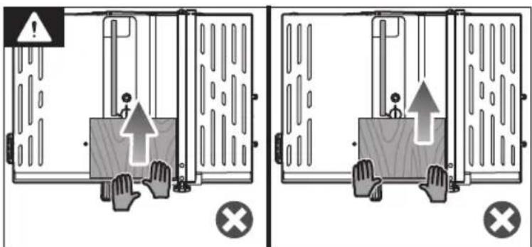
- Never cut more than one workpiece, stacked vertically or horizontally. The saw blade could pick up one or more pieces and cause kickback.
- When restarting the saw with the saw blade in the workpiece, centre the saw blade in the kerf so that the saw teeth are not engaged in the material. If the saw blade binds, it may lift up the workpiece and cause kickback when the saw is restarted.
- Keep saw blades clean, sharp, and with sufficient set. Never use warped saw blades or saw blades with cracked or broken teeth. Sharp and properly set saw blades minimise binding, stalling and kickback.
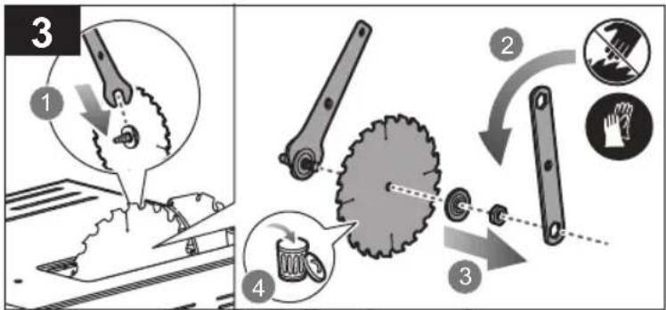
■ Turn off the table saw and disconnect the battery pack when removing the table insert, changing the saw blade or making adjustments to the riving knife, anti-kickback pawls or saw blade guard, and when the machine is left unattended. Precautionary measures will avoid accidents.
- Never leave the table saw running unattended. Turn it off and don't leave the product until it comes to a complete stop. An unattended running saw is an uncontrolled hazard.
- Locate the table saw in a well-lit and level area where you can maintain good footing and balance. It should be installed in an area that provides enough room to easily handle the size of your workpiece. Cramped, dark areas, and uneven slippery floors invite accidents.
■ Frequently clean and remove sawdust from under the saw table and/or the dust collection device. Accumulated sawdust is combustible and may self-ignite.
■ The table saw must be secured. A table saw that is not properly secured may move or tip over.
■ Remove tools, wood scraps, etc. from the table before the table saw is turned on. Distraction or a potential jam can be dangerous.
■ Always use saw blades with correct size and shape (diamond versus round) of arbour holes. Saw blades that do not match the mounting hardware of the saw will run off-centre, causing loss of control.
■ Never use damaged or incorrect saw blade mounting means such as flanges, saw blade washers, bolts or nuts. These mounting means were specially designed for your saw, for safe operation and optimum performance.
■ Never stand on the table saw, do not use it as a stepping stool. Serious injury could occur if the product is tipped or if the cutting tool is accidentally contacted.
■ Make sure that the saw blade is installed to rotate in the proper direction. Do not use grinding wheels, wire brushes, or abrasive wheels on a table saw. Improper saw blade installation or use of accessories not recommended may cause serious injury.
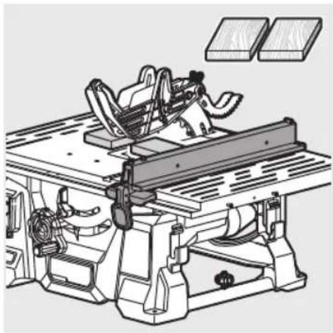
RIP FENCE USE
⚠ WARNING! To reduce the risk of injury, always make sure the rip fence is parallel to the blade before beginning any operation.
■ Loosen the rip fence by lifting the locking lever.
- Place the rear lip on the rear of the saw table and pull slightly toward the front of the unit.
■ Lower the front end of the rip fence onto the guide surfaces on top of the front rail.
■ Check for smooth gliding action.
■ Position the rip fence the desired distance from the blade.
■ With the rip fence flat on the saw table, push the fence towards the front rail to align the fence to the blade.
WARNING! Lock the fence at the intended cut size first then move the work piece up to the fence. Do not place the work piece first then move your fence up to it to lock the fence. This may result in a misaligned fence which could pinch the workpiece against the saw blade and create kickback.
- Push the locking lever down to align and secure the fence. When securely locked, the locking lever should point downward.
NOTE: Ensure the locking lever secures the rip fence in place.
NOTE: If the rip fence is not parallel to the blade, adjustments are needed.
ADDITIONAL SAFETY WARNINGS FOR TABLE SAWS
■ Ambient temperature range for tool during operation is between 0 °C and 40°C.
■ Ambient temperature range for tool storage is between 0 °C and 40°C.
■ The recommended ambient temperature range for the charging system during charging is between 10 °C and 38°C.
SPECIFIC SAFETY INSTRUCTIONS FOR WOOD CUTTING BLADE
- Please read the manual and instructions carefully before using the saw blade and the power tool.
■ The power tool must be in good condition, the spindle without deformation and vibration.
■ Ensure the operator is adequately trained in safety precautions, adjustment and operation of the power tool.
■ Always wear goggles and ear protection when using the power tool. It is recommended to wear gloves, sturdy non slipping shoes and apron.
■ Before using any accessory, consult the instruction manual. The improper use of an accessory can cause damage and increase the potential for injury.
- Keep the blade clean. This includes saw dust and particularly sticky substances like wood resin. A clean blade cuts more accurately and safely.
■ Use only blades specified in this manual, complying with EN 847-1.
- Observe the maximum speed marked on the saw blade. Ensure the speed marked on the saw blade is at least equal to the speed marked on the saw.
■ Always use blades with correct size and shape of arbor holes. Blades that do not match the mounting hardware of the saw will run eccentrically, causing loss of control.
- Do not use saw blades with a body thickness greater or a width of the groove cut (kerf) smaller than the thickness of the riving knife.
- Do not use blades of larger or smaller diameter than recommended. Do not use any loose washers or spacers to make the blade fit onto the spindle.
- Check the tips of the saw blade for damage or abnormal appearance before each use. Tips that are damaged or loose can become flying objects in use and increase the risk of personal injury.
- Do not use cracked or distorted saw blades. Do not use saw blades that are damaged or deformed.
- Scrap the saw blade if damaged, deformed, distorted or cracked, repairing is not permitted.
■ Do not use HSS blades.
■ Ensure the saw blade is mounted correctly, tighten the arbor nut securely before use.
■ Fastening screw and nuts shall be tightened using the appropriate spanner, etc.
■ Using an extension on the spanner or tightening using hammer blows is not permitted.
■ Make sure the blade and flanges are clean and the recessed sides of the collar are against the blade.
■ Make sure the blade rotates in the correct direction and does not contact any part of the machine or guarding system.
■ Before work, make a dummy cut without the motor turned on so the position of the blade, operation of the guards with respect to other product parts and work piece may be checked.
■ Never leave the power tool unattended.
■ Do not apply lubricants on the blade when it is running.
■ Never attempt to stop the power tool in motion rapidly by jamming a tool or other means against the blade, serious accidents can be caused unintentionally in this way.
■ Disconnect the power tool from the mains supply or remove battery pack before changing blades or carrying out maintenance.
■ Pay attention to blade packing and unpacking, it is easy to be injured by the sharp blade tips.
■ Use a blade holder or wear gloves when handling a saw blade. Remember, the blade will be hot after cutting operations.
- Keep and store the blade in original packaging or other suitable packaging, keep in dry conditions and away from chemicals which may damage the blade.
ADDITIONAL BATTERY SAFETY WARNINGS
■ To reduce the risk of fire, personal injury, and product damage due to a short circuit, never immerse your tool, battery pack or charger in fluid or allow a fluid to flow inside them. Corrosive or conductive fluids, such as seawater, certain industrial chemicals, and bleach or bleach-containing products, etc., can cause a short circuit.
■ Ambient temperature range for battery during use is between 0 °C and 40°C.
■ Ambient temperature range for battery storage is between 0 °C and 20°C.
TRANSPORTING LITHIUM BATTERIES
Transport the battery in accordance with local and national provisions and regulations.
Follow all special requirements on packaging and labelling when transporting batteries by a third party. Ensure that no batteries can come in contact with other batteries or conductive materials while in transport by protecting exposed connectors with insulating, non-conductive caps or tape. Do not transport batteries that are cracked or leaking. Check with the forwarding company for further advice.
KNOW YOUR PRODUCT
See page 169.
-
Work table
-
Bevel angle lock lever
-
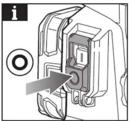
On/off switch
-
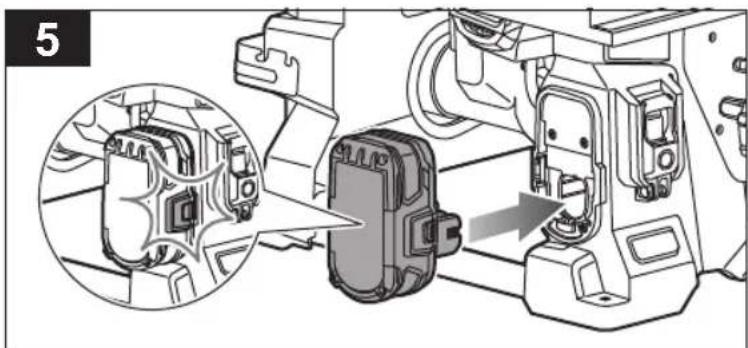
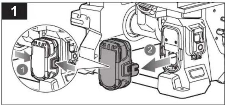
Battery port
-
Height and bevel adjustment wheel
-
Adjustment wheel handle
-
Mitre guide
-
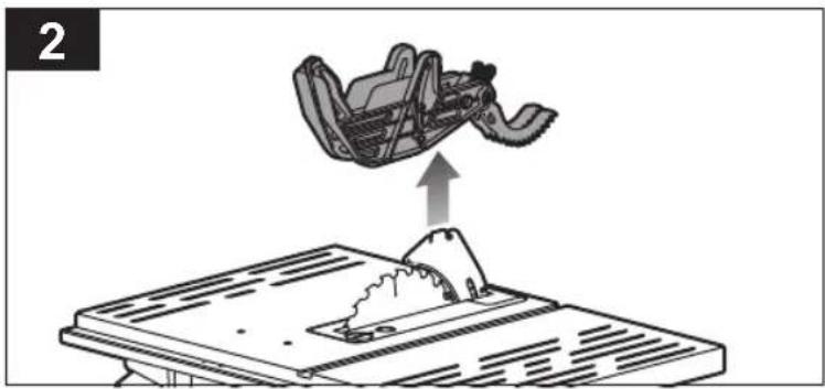
Saw blade guard
-
Anti-kickback pawls
-
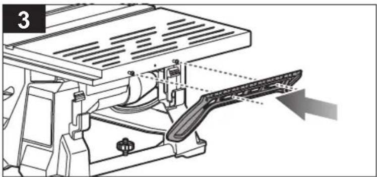
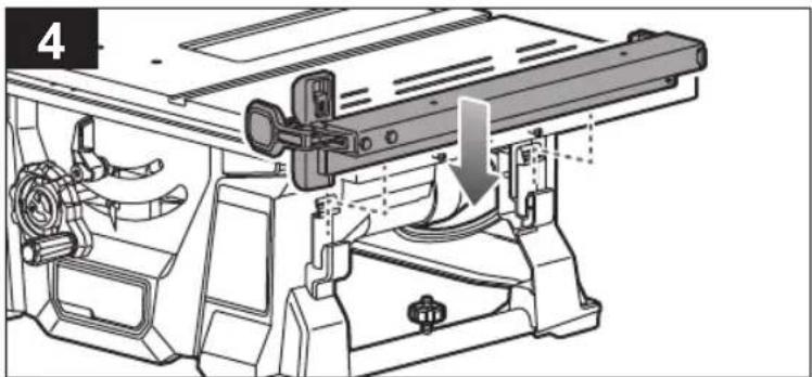
Rip fence
-
Saw blade
-
Riving knife
-
Throat plate
-
Throat plate lock knob
-
Dust port
-
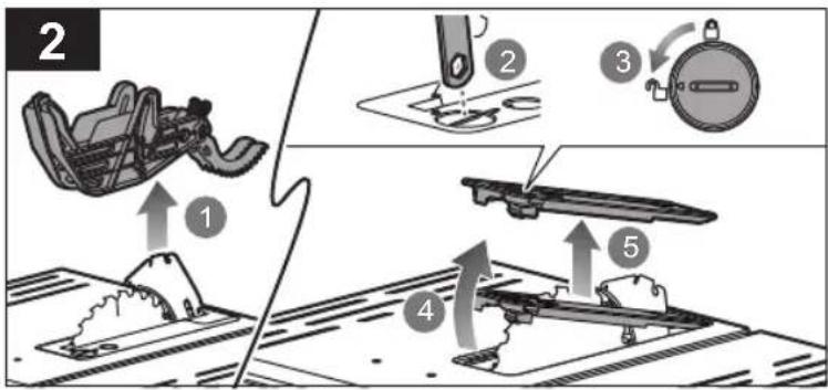
Storage (mitre gauge, riving knife, wrenches)
-
Mounting hole
-
Push stick
-
Dust port adaptor
-
Hex key
-
Closed end blade wrench
-
Open end blade wrench
-
Operator's manual
-
Bolt
-
Washer
-
Hex nut
-
Screwdriver
-
Battery pack
-
Charger
MAINTENANCE
- Do not modify the product in any way or use accessories not approved by the manufacturer. Your safety and that of others may be compromised.
- Do not use the product if any switches, guards, or other functions does not work as intended. Return to an authorised service centre for professional repair or adjustment.
- Do not make any adjustments whilst the saw blade is in motion.
■ Always make sure the battery pack has been removed from the product before making adjustments, lubricating or when doing any maintenance on the product.
■ Before and after each use, check the product for damage or broken parts. Keep the product in top working condition by immediately replacing parts with spares approved by the manufacturer.
■ The blade has sharp edges and may also remain hot after cutting operations. Exercise extreme caution when cleaning an exposed blade. Wear gloves to protect yourself from personal injury.
■ Clean the saw and its accessories from dust regularly, especially moving parts including the blade guard. Use a hand brush or vacuum cleaner to remove dust effectively. Do not use compressed air.
■ For greater safety and reliability, all repairs, including changing brushes, should be performed by an authorised service centre.
⚠ WARNING! Do not attempt to disassemble the blade guard assembly for cleaning or repair. Damaged guards should not be used. Return to an authorised service centre for repair or replacement.
SYMBOLS ON THE PRODUCT

Safety alert

European Conformity Mark

British Conformity Mark

Ukraine Conformity Mark

EurAsian Conformity Mark

Please read the instructions carefully before starting the product.

Wear ear protection.

Wear eye protection.

Wear safety gloves.

Keep hands away from the cutting area and sharp blade.

Do not expose to rain or use in damp locations.

Blade width of cut (kerf)

Number of teeth on this saw blade

For cutting wood and analogous material

Not for cutting metals

Blade rotation direction (shown on saw blade)

Do not dispose of waste batteries, waste electrical and electronic equipment as unsorted municipal waste. Waste batteries and waste electrical and electronic equipment must be collected separately. Waste batteries, waste accumulators, and light sources have to be removed from the equipment. Check with your local authority or retailer for recycling advice and collection point. According to local regulations, retailers may have an obligation to take back waste batteries and waste electrical and electronic equipment free of charge. Your contribution to the reuse and recycling of waste batteries and waste electrical and electronic equipment helps to reduce the demand of raw materials. Waste batteries, in particular containing lithium, and waste electrical and electronic equipment contain valuable and recyclable materials, which can adversely impact the environment and the human health if not disposed of in an environmentally compatible manner. Delete personal data from waste equipment, if any.
SYMBOLS IN THIS MANUAL

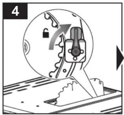
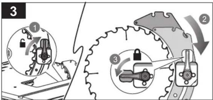
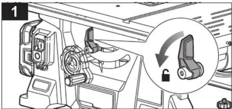
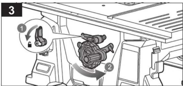
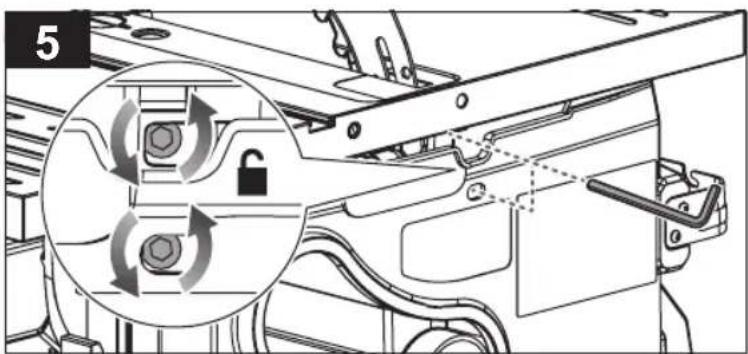
Lock

Unlock

Parts or accessories sold separately

Note

Warning
SYMBOLES APPLIQUÉS SUR LE PRODUIT

Alerte de sécurité

MACHEN SIE SICH MIT IHREM PRODUKT VERTRAUT
Siehe Seite 169.
SYMBOLE AUF DEM PRODUKT

Sicherheitswarnung

text_image
Collection of black-and-white safety symbols including hand, no litter, sandbar, gear, and circuit board.
text_image
Image displaying five black icons: lock, open padlock, shopping cart, information icon, and warning symbol.
Blocco
Sblocco
WAARSCHUWINGEN INZAKE BEWARING
WAARSCHUWINGEN VOOR ZAAGPROCEDURE
SYMBOLER PÅ PRODUKTET

Sikkerhedsadvarsel
SYMBOLER PÅ PRODUKTEN

Säkerhetsvarning

CE-märkning

SIKKERHET PÅ ARBEIDSOMRÅDET
SYMBOLER PÅ PRODUKTET

Sikkerhetsadvarsel

Europeisk samsvarsmerking

Britisk samsvarsmerking

001
Ukrainsk samsvarsmerking
EurAsian Konformitetstegn

ÜLDISED OHUTUSREEGLID
OBOZNÁMTE SA S VAŠÍM PRODUKTOM
Vid' strana 169.
text_image
Exploded view diagram of a mechanical device with numbered parts and a 5 mm scale indicator.

text_image
24 25 28 2926
27
x4
Ø8 x8x4 M8
M8

text_image
1
x4
text_image
Diagram illustrating a mechanical assembly with numbered components and a shopping cart icon, likely for repair or maintenance.
text_image
Technical diagram showing mechanical assembly with numbered component and magnified detail view
text_image
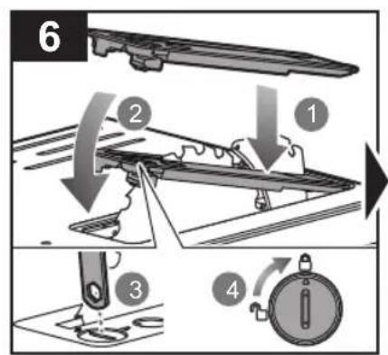
6
①
②
③
④

text_image
7
①
②

text_image
Diagram illustrating vehicle gear meshing with warning symbols and directional arrows, showing correct and incorrect states.

natural_image
Mechanical assembly diagram showing a component being inserted into a housing, with a magnified inset highlighting internal structure (no text or symbols)
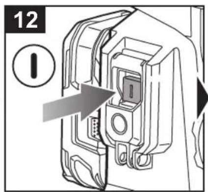
text_image
12
①
natural_image
Diagram of a device internal component with an arrow pointing to a circular symbol (no text or labels)

text_image
3
1
2
3
4
text_image
4

text_image
5
1
2
6
natural_image
Mechanical assembly diagram showing a lever mechanism with motion arrows (no text or symbols)

text_image
9
1
2
3
4

text_image
10
11
natural_image
Technical line drawing of a machine tool with no visible text or symbols

text_image
Technical diagram illustrating mechanical assembly steps with numbered components and directional arrows indicating motion or movement.

text_image
2

natural_image
Technical line drawing of a machine tool with no visible text or symbols

text_image
Technical diagram showing two mechanical assembly states with warning symbols and directional arrows indicating movement or force.
text_image
Diagram illustrating two mechanical or electrical switch configurations with warning symbols and cross indicators.

natural_image
Technical line drawing of a mechanical assembly with three rectangular blocks above (no text or symbols)

text_image
-60°- 0°/
0° - 60°

text_image
2
①
②

text_image
Diagram illustrating two mechanical or electrical assembly states with directional arrows and warning symbols, showing hand positioning and mounting points.

text_image
Technical diagram showing mechanical assembly steps with numbered annotations

natural_image
Diagram of a machine tool cutting through a saw blade, showing cutting direction and cutting depth (no text or symbols)

text_image
Technical diagram showing mechanical assembly with labeled parts and directional arrows indicating movement or assembly.
text_image
Diagram illustrating a mechanical assembly process with numbered steps and component illustrations
flowchart
graph TD
    A["Step 1: Lock mechanism"] --> B["Step 2: Rotation of gear"]
    B --> C["Step 3: Lock mechanism with clockwise rotation"]

text_image
4
①
②
③
④
natural_image
Mechanical assembly diagram showing a component being inserted into a housing, with an inset close-up of the internal structure (no text or symbols visible)


text_image
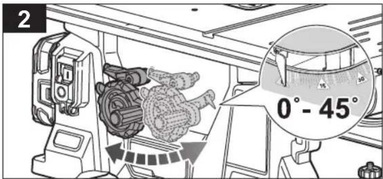
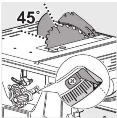
0° - 45°
text_image
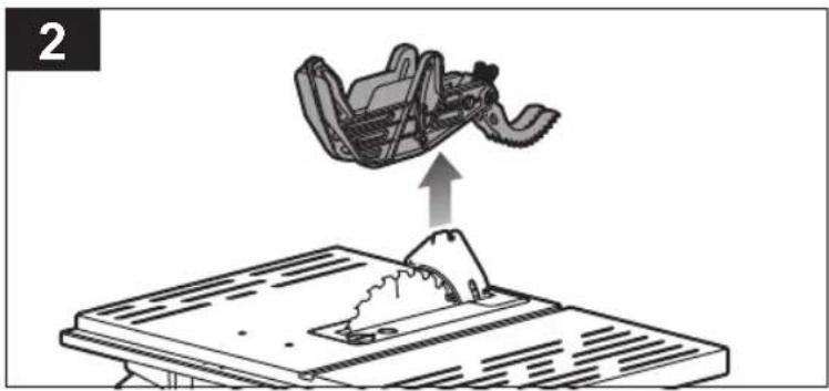
1
text_image
2
0° - 45°

text_image
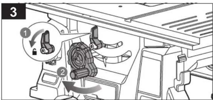
3

text_image
Technical diagram showing mechanical assembly with labeled parts, including a component labeled '1' and a base assembly with arrows indicating motion.

text_image
90°

text_image
Technical diagram showing mechanical assembly with labeled components and directional arrows indicating movement or assembly steps
text_image
2
text_image
Diagram showing mechanical assembly with numbered parts and directional arrows indicating motion or movement

text_image
4
1
2
90°
text_image
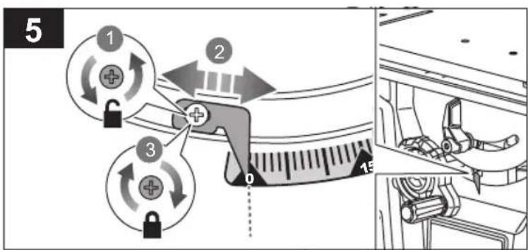
5
1
2
3
0
15
text_image
45°

text_image
Technical diagram showing mechanical assembly with labeled parts and directional arrows indicating movement or assembly.
text_image
2
text_image
Diagram showing mechanical assembly with labeled parts and directional arrows indicating motion or movement

text_image
4
1
45°
2

text_image
5
1
2
3
45
15
30
45

natural_image
Two technical diagrams showing a mechanical component being cut off on a flat surface, with no visible text or symbols.

text_image
Technical diagram showing mechanical assembly with labeled components and directional arrows indicating movement or assembly steps.

text_image
Diagram illustrating a mechanical assembly process with numbered steps and component illustrations

text_image
Diagram illustrating mechanical gear assembly steps with labeled components and directional arrows

text_image
4
1
2
3
0°
text_image
5

text_image
6

text_image
7
text_image
8
①
②
③
④

natural_image
Technical line drawing of a mechanical assembly with a spray bottle and component, showing internal components and alignment (no text or symbols)

text_image
Technical diagram showing mechanical assembly with labeled components and directional arrows indicating movement or assembly steps

text_image
Diagram illustrating a mechanical assembly process with numbered steps and component illustrations

text_image
3
1
2

natural_image
Technical diagram of a machine tool with gear and directional arrows indicating movement (no text or symbols)
text_image
5
text_image
6
text_image
7

text_image
8
1
2

text_image
9
①
②
③
④

natural_image
Technical line drawing of a mechanical assembly with no visible text or symbols

text_image
Technical diagram showing mechanical assembly with labeled components and directional arrows indicating movement or assembly steps

text_image
Diagram illustrating a mechanical assembly process with numbered steps and component illustrations
text_image
3
1
2
natural_image
Technical diagram of a machine tool with gear and directional arrows indicating movement (no text or symbols)
text_image
5
①
②
text_image
6

text_image
7
2
1

text_image
8
1
2

text_image
9
①
②
③
④
text_image
20 30
50
text_image
Technical diagram showing mechanical assembly with labeled components and directional arrows indicating movement or assembly steps

natural_image
Diagram showing a car interior being lifted by an upward arrow above a roof structure (no text or symbols)

text_image
3
1
2
3
0°

text_image
4
50mm
1
2

text_image
5
0 10 20 30
①
②
③
50
+

natural_image
Mechanical assembly diagram showing a crane lifting a beam with a lock icon and warning symbol (no text or labels)

text_image
Technical diagram showing mechanical assembly with numbered components and a magnified inset highlighting a specific component.

text_image
2

natural_image
Mechanical assembly diagram showing a gear mechanism with a highlighted component (no text or symbols present)
text_image
Technical diagram showing mechanical assembly with labeled components and a magnified inset view of a component detail.

text_image
Diagram illustrating a waste sorting process with labeled steps and directional arrows indicating material movement.
natural_image
Technical line drawing of a mechanical assembly with no visible text or symbols

natural_image
Diagram showing a gear cutting through a machine cutterhead with an upward arrow indicating motion (no text or symbols)
text_image
Technical diagram showing mechanical assembly with labeled components and directional arrows indicating movement or assembly steps

text_image
Diagram illustrating a mechanical assembly process with numbered steps and component illustrations
text_image
Diagram illustrating mechanical assembly steps with numbered instructions and labeled components

text_image
4
1
3
2
4
④
①
②

text_image
5
1
2
3
4

natural_image
Technical line drawing of a machine tool assembly with exploded view (no text or labels)

natural_image
Technical line drawing of a mechanical assembly with rotating components and directional arrows (no text or symbols)

text_image
Technical diagram showing mechanical assembly steps with numbered annotations and a magnified inset illustrating the process.
natural_image
Technical diagram of a mechanical device with a lever and handle, showing internal components and alignment arrows (no text or symbols)
natural_image
Technical line drawing of a mechanical assembly with no visible text or symbols

natural_image
Mechanical assembly diagram showing a foot pressing down on a vehicle chassis with no visible text or symbols
natural_image
Line drawing of a mechanical machine on a wheeled platform (no text or symbols)

text_image
Technical diagram showing mechanical assembly with labeled components and directional arrows indicating movement or assembly.

natural_image
Technical illustration of a mechanical assembly with no visible text or symbols

natural_image
Illustration of a mechanical device with four hands raised and three upward arrows indicating motion or force (no text or symbols)

natural_image
Line drawing of a manual labor machine on a wheeled cart (no text or symbols)
| English Français Deutsch Español Italiano Nederlands Português |
| Battery and charger Batterie et chargeur Akku und Ladegerät Bateria y cargador Batteria e caricatore | Accu en lader Bateria e carregador | |
| Compatible battery packs (not included) | Pack batterie compatible (non compris) | Kompatible Akkupacks (nicht im Lieferumfang enthalten) | Packs de Bateria compatibles (no incluido) | Gruppo batterie compatibile (non incluso) | Compatibel accupack (niet inbegrepen) | Baterias compatíveis (não incluída) |
| Compatible chargers (not included) | Chargeur compatible (non compris) | Kompatibles Ladegerät (nicht im Lieferumfang enthalten) | Cargador compatible (no incluido) | Caricatore compatibile (non incluso) | Compatibele oplader (niet inbegrepen) | Carregador compatível (não incluída) |
| Dansk | Svenska | Suomi | Norsk | Русский | Polski | Čeština | |
| Batteri og oplader | Batteri och laddare | Akku ja laturi | Batteri og lader | Батарея и зарядное устройство | Akumulator i ładowarka | Baterie a nabíječka | |
| Kompatibelt batteri (medfølger ikke) | Kompatibelt batteripack (inte inkluderat) | Yhteensopiva akku (ei mukana) | Kompatible batteripakker (ikke inkludert) | Совместимая аккумуляторная батарея (не входит в комплект поставки) | Pasujące akumulatory (nie dołączona) | Kompatibilní akumulátor (nepříbalen) | RB18.. |
| Kompatibel oplader (medfølger ikke) | Passande laddare (inte inkluderat) | Yhteensopiva laturi (ei mukana) | Kompatibel lader (ikke inkludert) | Совместимое зарядное устройство (не входит в комплект поставки) | Odpowiednia ładowarka (nie dołączona) | Kompatibilní nabíječka (nepříbalen) | BCL1418..H RC18.. |
| Magyar Română Latviski Lietuviškai Eesti Hrvatski |
| Akkumulátor és töltő | Baterie și încărcător | Akumulators un lădëtăjs | Baterija ir jkroviklis | Aku ja laadija | Baterija i punjač | |
| Kompatibilis akkumulátor (nem tartozék) | Acumulatori compatibili (neinclus) | Saderīgu akumulatoru komplekts (nav kompl.) | Suderinamas baterijos paketas (nepridedama) | Ühilduvad akupaketid (ei ole komplektis) | Kompatibilno pakiranje baterija (nije uključeno) | RB18.. |
| Kompatibilis töltő (nem tartozék) | Încărcător compatibil (neinclus) | Saderīgs lădëtăjs (nav kompl.) | Tinkamas jkroviklis (nepridedama) | Kasutatav laadija (ei ole komplektis) | Kompatibilni punjač (nije uključeno) | BCL1418..H RC18.. |
The declared noise emission value(s) have been measured in accordance with a standard test method, and may be used for comparing one tool with another.
The declared noise value(s) may also be used in a preliminary assessment of exposure.
The noise emissions during actual use of the power tool can differ from the declared values depending on the ways in which the tool is used especially what kind of workpiece is processed.
Identify safety measures to protect the operator based on an estimation of exposure in the actual conditions of use (taking account of all parts of the operating cycle such as the times when the tool is switched off and when it is running idle in addition to the trigger time).
Wear hearing protection. Exposure to noise can cause hearing loss.
FR

AVERTISSEMENT
EN RYOBI WARRANTY APPLICATION CONDITIONS
In addition to any statutory rights resulting from the purchase, this product is covered by a warranty as stated below.
-
The warranty period is 24 months for consumers and commences on the date the product was purchased. This date has to be documented by an invoice or other proof of purchase. The product is designed and dedicated to consumer and private use only. So there is no warranty provided in case of professional or commercial use. This warranty applies only on new products.
-
There is a possibility to extend for a part of the range of power tools (AC/DC) the warranty period over the period described above using the registration on the www.nyobitools.eu website. The eligibility of products for extended warranty is clearly displayed in stores and / or on packaging and is contained within the product documentation. The end user is required to register his/her newly-acquired products online within 30 days from the date of purchase. The end user may register for the extended warranty in his/her country of residence if listed on the online registration form where this option is valid. Furthermore, end users must give their consent to the storage of their personal data that is required to be entered online. They must also accept the terms and conditions. The registration confirmation receipt, which is sent out by e-mail, and the original invoice showing the date of purchase will serve as proof of the extended warranty.
-
The warranty covers all defects of the product during the warranty period due to faults in workmanship or material at the purchase date. The warranty is limited to repair and/or replacement and does not include any other obligations including but not limited to incidental or consequential damages. The warranty is not valid if the product has been misused, used contrary to the instruction manual, or has been incorrectly connected to a power supply. This warranty does not apply to:
– any damage to the product that is the result of improper or lack of maintenance
– any product that has been altered or modified
– any product where original identification (trade mark, serial number) markings have been defaced, altered or removed
– any damage caused by non-observance of the instruction manual
– any product not displaying the CE approval mark on the rating plate
– any product that has been attempted to be repaired by a non-authorised warranty service centre or without prior authorisation by Techtronic Industries
– any product connected to improper power supply (amps, voltage, frequency)
– any damage caused by external influences (water, chemical, physical, shocks) or foreign substances
– normal wear and tear spare parts
– inappropriate use, overloading of the tool
– use of non-approved accessories or parts
- Power tool accessories provided with the tool or purchased separately, including but not limited to screw driver bits, drill bits, abrasive discs, sand paper and blades, lateral guide, etc.
- Components (parts and accessories) subject to natural wear and tear, including but not limited to service & maintenance kits, carbon brushes, bearings, chuck, SDS drill bit attachment or reception, power cord, auxiliary handle, transport carry case, sanding plate, dust bag, dust exhaust tube, felt washers, impact wrench pins & springs, etc.
-
For servicing, the product must be sent or presented to a RYOBI authorised service station listed for each country in the following list of service station addresses. In some countries your local RYOBI dealer undertakes to send the product to the RYOBI service organisation. When sending a product to a RYOBI service station, the product should be safely packed without any dangerous contents such as petrol, marked with sender's address and accompanied by a short description of the fault.
-
A repair / replacement under this warranty is free of charge. It does not constitute an extension or a new start of the warranty period. Exchanged parts or products become our property. In some countries delivery charges or postage will have to be paid by the sender. Your statutory rights arising from the purchase of the product remain unaffected
-
This warranty is valid in the European Community, Switzerland, Iceland, Norway, Liechtenstein, Turkey, Russia, and the United Kingdom. Outside these areas, please contact your authorised RYOBI dealer to determine if another warranty applies.
AUTHORISED SERVICE CENTRE
Any request or issue with the product can be addressed to your local authorised service centres (visit www.ryobitools.eu) or directly to: Techtronic Industries GmbH, Max Eyth Straße 10, 71364 Winnenden, Germany. Please state the serial number and product type printed on the label.
FR RYOBI CONDITIONS D'APPLICATION DE LA GARANTIE
Table saw
Brand: RYOBI | Manufacturer ^1 | Model number ^2 | Serial number range ^3
We declare as the manufacturer under our sole responsibility that the product mentioned below fulfills all the relevant provisions of the following European Directives, European Regulations and harmonised standards ^4 Authorised to compile the technical file: ^5
Max-Eyth-Straße 10, 71364 Winnenden, Germany
^2 RTBS18X
^3 48630801000001 - 48630801999999
^4 2006/42/EC, 2014/30/EU, 2011/65/EU.
EN 55014-1:2017+A11:2020, EN 55014-2:2015,
EN 61000-3-2:2014, EN 61000-3-3:2013,
EN 62841-1: 2015, EN 62841-3-1:2014+A11:2017+A12:2021,
EN IEC 63000:2018

Alexander Krug
Managing Director
Max-Eyth-Straße 10, 71364 Winnenden, Germany
Manufacturer: Techtronic Industries GmbH
Max-Eyth-Straße 10, 71364 Winnenden, Germany
We declare as the manufacturer under our sole responsibility that the product mentioned below
Table saw
Brand: RYOBI
Model number: RTBS18X
Serial number range: 48630801000001 - 48630801999999
fulfills all the relevant provisions of the following Regulations; S.I. 2008/1597 (as amended), S.I. 2016/1091 (as amended), S.I. 2012/3032 (as amended) and that the following designated standards have been used:
BS EN 55014-1:2017+A11:2020, BS EN 55014-2:2015,
BS EN 61000-3-2:2014, BS EN 61000-3-3:2013,
BS EN 62841-1:2015, BS EN 62841-3-1:2014+A11:2017+A12:2021,
BS EN IEC 63000:2018

Alexander Krug
Managing Director
Authorised to compile the technical file:
Techtronic Industries (UK) Ltd
Parkway
Marlow Bucks SL7 1YL
UK


EN RYOBI is a trade mark of Ryobi Limited, and is used under license.
natural_image
Three vertical panels showing diagonal striped patterns in grayscale, no text or symbols present

Techtronic Industries GmbH
Max-Eyth-Straße 10,
71364 Winnenden, Germany
Techtronic Industries (UK) Ltd
Parkway
Marlow Bucks SL7 1YL
UK
20230109v1c