RTMS1800 - Electric saw RYOBI - Free user manual and instructions
Find the device manual for free RTMS1800 RYOBI in PDF.
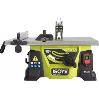
| Product type | Miter saw and bench saw combined |
| Brand | RYOBI |
| Model | RTMS1800 |
| Power | 1800 W |
| Supply voltage | 230 V ~ 50 Hz |
| Insulation class | II (double insulation) |
| Cutting capacity (table mode) | 60 mm (max) |
| Cutting capacity (miter mode) | 70 × 130 mm (max) |
| Miter angle range | -45° to +45° |
| Bevel range | 0° to 45° |
| Laser guide | Class 2, 650 nm, ≤1 mW |
| Recommended blade type | Blades compliant with EN 847-1 for wood |
| Machinable materials | Wood only (no metal, no magnesium) |
| Safety | Mandatory hearing and eye protection, protective guard, riving knife, push stick |
| Maintenance | Clean ventilation slots, check carbon brushes, do not lubricate blade while rotating |
| Warranty | 24 months (extension possible via online registration within 8 days) |
| Standards | CE, GOST-R, EN 61029, EN 55014, EN 61000 |
| Repairability | Repairs exclusively by an authorized after-sales service |
| Weight | Approximately 20 kg |
| Dimensions (L×W×H) | Approximately 800 × 600 × 400 mm |
Frequently Asked Questions - RTMS1800 RYOBI
User questions about RTMS1800 RYOBI
0 question about this device. Answer the ones you know or ask your own.
Ask a new question about this device
Download the instructions for your Electric saw in PDF format for free! Find your manual RTMS1800 - RYOBI and take your electronic device back in hand. On this page are published all the documents necessary for the use of your device. RTMS1800 by RYOBI.
USER MANUAL RTMS1800 RYOBI
natural_image
Industrial cutting machine with visible blade and base components (no text or symbols)

| Important! | It is essential that you read the instructions in this manual before assembling, operating and maintaining this machine. |
| Attention! | Il est essentiel que vous lisiez les instructions contenues dans ce mode d'emploi avant d'assembler, d'entretenir et d'utiliser cette machine. |
| Achtung! | Es ist wichtig, dass Sie vor Zusammenbau, Benutzung und Wartung dieser Maschine die Anweisungen in dieser Anleitung lesen. |
| ¡Atención! | Antes de montar, de utilizar o de realizar el mantenimiento de esta máquina es muy importante que lea las instrucciones de este manual. |
| Attenzione! | È essenziale leggere le istruzioni contenute nel manuale prima di montare, mettere in funzione e svolgere le operazioni di manutenzione sull'utensile. |
| Let op! | Het is van essentieel belang dat u de instructies in deze gebruiksaanwijzing leest voor u deze machine monteert, bedient en onderhoudt. |
| Atenção! | É essencial que leia as instruções neste manual antes de montar, operar e efetuar manutenção a esta máquina. |
| OBS! | Det er meget vigtigt, at man læser anvisningerne i denne brugsanvisning, inden maskinen samles, betjenes og vedligeholdes. |
| Observeral! | Det är viktigt att du läser instruktionerna i manualen före montering, användning och underhåll av maskinen. |
| Huomio! | On tärkeää, että luet tämän käsikirjan ennen tämän laitteen kokoamista, huoltoa ja käyttöä. |
| Advarse!! | Det er viktig at du leser instruksjonene i denne brukermanualen før du monterer, bruker og vedlikeholder maskinen. |
| Внимание! | Необходимо прочитать инструкции в данном руководстве перед сборкой, эксплуатацией и обслуживанием этого устройства. |
| Uwaga! | Koniecznie przeczytaj instrukcje zawarte w tym podręczniku przed montażem, obsługą oraz konserwacją tej maszyny. |
| Dûležité upozornění! | Neinstalujte, neprovádějte údržbu ani nepoužívejte tento nástroj dříve, než si přečtete pokyny uvedené v tomto návodu. |
| Figyelem! | Fontos, hogy a gép összeszerelése, használata és karbantartása előtt elolvassa a kézikönyvben található utasításokat. |
| Atenție! | Este esențial să citiți instrucțiunile din acest manual, înainte de asamblarea, operarea sau întreținerea acestui aparat. |
| Uzmanību! | Pirms ierīces montāžas, darbināšanas un apkopes veikšanas obligāti izlasiet norādījumus šajā rokasgrāmatā. |
| Dèmesio! | Prieš surinkdami, eksploatuodami ir prižiūrėdami šį jrenginį, būtina, kad perskaitytumėte nurodymus, pateiktus šiame naudotojo vadove. |
| Tähtis! | Enne masina kokkupanekut, kasutama ja hooldama hakkamist tuleb käesolevas juhendis esitatud juhised kindlasti läbi lugeda. |
| Upozorenje! | Vrlo je važno da ste prije sklapanja, rada i održavanja ovog stroja pročitali upute u ovom priručniku. |
| Pomembno! | Zelo pomembno je, da pred sestavljanjem, vzdrževanjem in uporabo te naprave preberete navodila v tem priročniku. |
| Dôležité! | Pred montázou, použivaním a údržbou tohto nástroja je dôležité, by ste si prečitali pokyny v tomto návode. |
| Важно! | Изключително важно е да прочетете инструкциите в настоящето ръководство, преди да сглобите и да работите с тази машина, както и да извършвате дейности по нейната поддръжка. |
Subject to technical modification / Sous réserve de modifications techniques / Technische Änderungen vorbehalten / Bajo reserva de modificaciones técnicas / Con riserva di eventuali modifiche tecniche / Technische wijzigingen voorbehouden /
When using electric tools, basic safety precautions should always be followed to reduce the electric shock and personal injury including the following. Read all these instructions before attempting to operate this product and save these instructions.
- Keep work area clear. Cluttered areas and benches invite injuries.
- Consider work area environment. Do not expose tools to rain. Do not use tools in damp or wet locations. Keep work area well lit. Do not use tools in the presence of flammable liquids or gases.
■ Guard against electric shock. Avoid body contact with earthed or grounded surfaces (e.g., pipes, radiators, ranges, refrigerators). - Keep other persons away. Do not let persons, especially children, be involved in the work, touch the tool or the extension cord, and keep them away from the work area.
■ Store idle tools. When not in use, tools should be stored in a dry locked-up place, out of reach of children. - Do not force the tool. It will do the job better and safer at the rate for which it was intended.
■ Use the right tool. Do not force small tools to do the job of a heavy duty tool. Do not use tools for purposes not intended, for example, do not use circular saws to cut tree limbs or logs.
■ Dress properly. Do not wear loose clothing or jewellery, they can be caught in moving parts. Non-skid footwear is recommended when working outdoors. Wear protective hair covering to contain long hair.
■ Use protective equipment. Use safety glasses. Use face or dust mask if working operations create dust.
■ Connect dust extraction equipment. If the tool is provided for the connection of dust extraction and collecting equipment, ensure these are connected and properly used. - Do not abuse the cord. Never yank the cord to disconnect it from the socket. Keep the cord away from heat, oil and sharp edges.
- Secure work. Where possible, use clamps or a vice to hold the work. It is safer than using your hand.
- Do not overreach. Keep proper footing and balance at all times.
- Maintain tools with care. Keep cutting tools sharp and clean for better and safer performance. Follow instruction for lubricating and changing accessories. Inspect tool cords periodically and if damaged, have them repaired by an authorized service facility. Inspect extension cords periodically and replace if damaged. Keep handles dry, clean and free from oil and grease.
■ Disconnect tools. When not in use, before servicing and when changing accessories such as blades, bits and cutters, disconnect tools from the power supply.
■ Remove adjusting keys and wrenches. Form the
habit of checking to see that keys and adjusting wrenches are removed from the tool before turning it on.
- Avoid unintentional starting. Ensure switch is in "off" position when plugging in.
nsk ■ of Us fire outdoor extension leads. When the tool is used outdoors, use only extension cords intended for outdoor use and so marked.
■ Stay alert. Watch what you are doing, use common sense and do not operate the tool when you are tired.
- Check damaged parts. Before further use of tool, it should be carefully checked to determine that it will operate properly and perform its intended function. Check for alignment of moving parts, binding of moving parts, breakage of parts, mounting and any other conditions that may affect its operation. A guard or other part that is damaged should be properly repaired or replaced by an authorized service centre unless otherwise indicated in this instruction manual. Have defective switches replaced by an authorized service centre.
- Do not use the tool if the switch does not turn it on and off.
WARNING
The use of any accessory or attachment other than the one recommended in this instruction manual may present a risk of personal injury.
■ Have your tool repaired by a qualified person. This electric tool complies with the relevant safety rules. Repairs should only be carried out by qualified persons using original spare parts, otherwise this may result in considerable danger to the user.
COMBINED MITRE AND BENCH SAW SAFETY WARNINGS
■ Wear ear protectors. Exposure to noise can cause hearing loss.
■ Always wear goggles when using the machine. It is recommended to wear gloves, sturdy non slipping shoes and apron.
■ Always wear safety goggles or safety glasses with side shields during power tool operation or when blowing dust. If operation is dusty, also wear a dust mask.
This machine is equipped with a specially configured power supply cord. If the power supply cord is damaged or otherwise defective, it must only be replaced by the manufacturer or by an authorized repair agent.
■ Make sure all locking knobs and clamp handles are tight before starting any operation.
- Do not use the saw without the guards in position, especially after a mode change. Keep guards in good working order and properly maintained.
■ Never place either hand in the blade area when the saw is connected to the electrical power source.
■ Never attempt to stop a machine in motion rapidly by jamming a tool or other means against the blade, serious accidents can be caused unintentionally in this way.
■ Before using any accessory, consult the instruction
English
manual. The improper use of an accessory can cause damage.
■ Do not modify the tool.
■ Ensure that any spacers and spindle rings used are suitable for the purpose as stated in this manual.
■ Select the correct blade for the material to be cut.
- Observe the maximum speed marked on the saw blade. Ensure the speed marked on the saw blade is at least equal to the speed marked on the saw.
■ Use a holder or wear gloves when handling a saw blade.
■ Ensure the saw blade is mounted correctly before use.
■ Make sure the blade rotates in the correct direction. Keep the blade sharp.
- Consider applying specially designed noise-reduction blades.
- Raise the blade from the kerf in the workpiece prior to releasing the switch.
■ Ensure the arm is securely fixed when performing bevel cuts.
■ Ensure the arm is securely fixed in the working position in the bench saw mode.
■ Ensure that the bench saw table is securely fixed at the chosen height.
- Do not wedge anything against the fan to hold the motor shaft.
The blade guard on your saw will automatically raise when the arm is brought down, it will lower over the blade when the arm is raised. The guard can be raised by hand when installing or removing saw blades or when inspecting the saw. Never raise the blade guard manually unless the saw is switched off.
- Keep the surrounding area of the machine well maintained and free of loose materials, such as chips and cut-offs.
■ Periodically check that the motor air slots are clean and free of chips.
■ Disconnect the machine from the mains before carrying out any maintenance work or when changing the blade.
■ Never perform any cleaning or maintenance work when the machine is still running and the head is not in the rest position.
■ When possible, always mount the machine to a bench and check for the security of fixing to bench.
- When performing mitre, bevel or compound mitre cuts, adjust the sliding mitre fence to ensure the correct clearance for the application.
■ Refrain from removing any cut-offs or other parts of the workpiece from the cutting area while the saw is running.
■ Before work, check that the machine is placed on an even surface with sufficient stability.
■ Before work, make a dummy cut without the motor turned on so the position of the blade, operation of the guards with respect to other machine parts and work piece may be checked.
■ Never cut light alloy, especially magnesium.
■ Do not use any abrasive or diamond discs.
In case of an accident or machine failure, immediately turn the machine off and disconnect machine from the power source.
■ Report the failure and mark the machine to prevent other people from using the defective machine.
- When the saw blade is blocked due to abnormal feed force during cutting, turn the machine off and disconnect it from power supply. Remove the workpiece and ensure that the saw blade runs free. Turn the machine on and start new cutting operation with reduced feed force.
■ Ensure that your position is always left or right of the cutting line.
■ Provide adequate general or localized lighting to prevent stroboscopic effect and hazards.
■ Ensure the operator is adequately trained in use, adjustment and operation of the machine.
■ Turn the machine off when unattended.
■ Connect the saw to a dust collection when sawing wood. Always consider factors influencing exposure of dust such as type of material to be machined (chip board produces more dust than wood), adjustment of saw blade, adjustment of local extraction as well as hoods, baffles and chutes, and air velocity of dust extractor.
- Keep the saw blade sharp and properly set.
- Do not attempt to operate on anything but the designated voltage.
■ Do not apply lubricants on the blade when it is running.
■ Ensure that bystanders do not stand behind the machine.
■ For your own safety, always mount the machine to a work bench using bolts.
■ Always use blades with correct size and shape of arbour holes. Blades that do not match the mounting hardware of the saw will run eccentrically, causing loss of control.
■ Use only blades specified in this manual, complying with EN 847-1.
- When cutting long or large workpieces, always provide adequate support to the sides of the table. The support should be at the same height as the table. Always keep hands away from path of table.
■ Disconnect the saw from the mains supply before changing blades or carrying out maintenance.
- Keep your hands out of the path of the saw blade.
■ Do not reach around behind the saw blade.
■ Do not stand on top of the unit.
■ During transportation, make sure the upper part of the saw blade is covered.
■ Do not use the upper guard for handling or transportation.
- Do not use the saw for cutting any material other than wood.
ADDITIONAL SAFETY RULES FOR TABLE SAW MODE
■ Replace the table insert when worn.
■ Never use your saw without the table insert.
2 | English
■ Ensure the table is securely fixed.
- When performing vertical straight cross-cuts, adjust the sliding fence correctly to ensure a clearance of 15 mm (maximum) between the saw blade and the end of the fence.
- Adjust the sliding fence correctly to avoid contact with the upper guard.
■ Never cut when riving knife and/or upper guard are removed.
■ Make sure the riving knife is adjusted to the correct distance from the blade (between 3 mm and 8 mm).
■ Always use the push stick. Never cut workpieces smaller than 30 mm.
Never place hands closer than 150 mm from the saw blade while cutting.
■ Always keep the push stick in its place when not in use.
- Do not use saw blades with a body thickness greater or a width of tooth smaller than the thickness of the riving knife.
■ Make sure the blade rotates in the correct direction and the teeth are pointing to the front of the saw bench.
■ Make sure all clamp handles are tight before starting any operation.
■ Ensure the arm is securely fixed when sawing. Only use the machine when the saw bench table is in horizontal position.
■ Slotting, rebating or grooving is not allowed.
ADDITIONAL SAFETY RULES FOR MITRE SAW MODE
-
Ensure the upper portion of the saw blade is completely enclosed. Never remove the upper blade guard when using the machine in mitre saw mode.
■ Never cut workpieces shorter than 160 mm.
■ Always clamp the workpiece safely.
It has been reported that vibrations from hand-held tools may contribute to a condition called Raynaud's Syndrome in certain individuals. Symptoms may include tingling, numbness and blanching of the fingers, usually apparent upon exposure to cold environments. Hereditary factors, exposure to cold and dampness, diet, smoking and work practices are all thought to contribute to the development of these symptoms. There are measures that can be taken by the operator to possibly reduce the effects of vibration: -
Keep your body warm in cold weather. When operating the unit wear gloves to keep the hands and wrists warm. It is reported that cold weather is a major factor contributing to Raynaud's Syndrome.
- After each period of operation, exercise to increase blood circulation.
- Take frequent work breaks. Limit the amount of exposure per day.
If you experience any of the symptoms of this condition, immediately discontinue use and see your doctor.
SAFETY INSTRUCTIONS FOR WOOD CUTTING BLADE
■ Please read the manual and instructions carefully before using the saw blade and the machine.
■ The machine must be in good condition, the spindle without deformation and vibration.
- Do not use the saw without the guards in position, keep guards in good working order and properly maintained.
■ Ensure the operator is adequately trained in safety precautions, adjustment and operation of the machine.
■ Always wear goggles and ear protection when using the machine. It is recommended to wear gloves, sturdy non slipping shoes and apron.
■ Before using any accessory, consult the instruction manual. The improper use of an accessory can cause damage and increase the potential for injury.
■ Use only blades specified in this manual, complying with EN 847-1.
- Observe the maximum speed marked on the saw blade. Ensure the speed marked on the saw blade is at least equal to the speed marked on the saw.
■ Always use blades with correct size and shape of arbour holes. Blades that do not match the mounting hardware of the saw will run eccentrically, causing loss of control.
- Do not use saw blades with a body thickness greater or a width of tooth smaller than the thickness of the riving knife (for table saw or in table saw mode).
- Do not use blades of larger or smaller diameter than recommended. Do not use any spacers to make the blade fit onto the spindle.
- Check the tips of the saw blade for damage or abnormal appearance before each use. Tips that are damaged or loose can become flying objects in use and increase the chance of personal injury.
- Do not use cracked or distorted saw blades. Do not use saw blades that are damaged or deformed.
- Scrap the saw blade if damaged, deformed, distorted or cracked, repairing is not permitted.
■ Do not use HSS blades.
■ Ensure the saw blade is mounted correctly, tighten the arbor nut securely before use. (tightening torque approx. 12-15 Nm).
■ Fastening screws and nuts shall be tightened using the appropriate spanner.
■ Extension of the spanner or tightening using hammer blows is not permitted.
■ Make sure the blade and flanges are clean and the recessed sides of the collar are against the blade.
■ Make sure the blade rotates in the correct direction.
■ Before work, make a dummy cut without the motor turned on so the position of the blade, operation of the guards with respect to other machine parts and work piece may be checked.
■ Never leave the machine unattended.
■ Do not apply lubricants on the blade when it is running.
■ Never perform any cleaning or maintenance work when
the machine is still running and the head is not in the rest position.
■ Never attempt to stop a machine in motion rapidly by jamming a tool or other means against the blade, serious accidents can be caused unintentionally in this way.
■ Disconnect the saw from the mains supply before changing blades or carrying out maintenance.
■ Pay attention to blade packing and unpacking, it is easy to be injured by the sharp blade tips.
■ Use a blade holder or wear gloves when handling a saw blade.
- Keep and store the blade in original packaging or other suitable packaging, keep in dry conditions and away from chemicals which may damage the blade.
LASER SAFETY RULES
The laser radiation used in this saw is Class 2 with maximum ≤1mW and 650nm wavelengths. Do not stare into the laser beam. Failure to comply with the rules could result in serious personal injury.
LASER RADIATION DO NOT STARE INTO BEAM CLASS 2 LASER PRODUCT λ: 650nm; P≤1mW EN 60825-1:2007
We have supplied you with an adhesive label in your language and now request that you please apply this over the top of the existing English language label that is located on the side of the tool prior to first commissioning the machine.
■ Do not stare into beam during operation.
■ Do not project the laser beam directly into the eyes of others. Serious eye injury could result.
- Do not place the laser in a position that may cause anyone to stare into the laser beam intentionally or unintentionally.
■ Do not use optical tools to view the laser beam.
- Do not operate the laser around children or allow children to operate the laser.
■ Do not attempt to repair the laser device by yourself.
- Do not attempt to change any parts of the laser device by yourself.
■ Any repairs must only be carried out by the laser manufacturer or authorized service agent.
■ Do not replace the laser with a different type.
INTENDED USE
This machine is designed for ripping and cross cutting operations on wood exclusively. It must be fixed securely to a suitable height work bench, and is intended to be operated by one person only.
In table saw mode, it is for through cuts only, no cutting of slots or rebates. The maximum cutting capacity is 60mm.
In mitre saw mode, horizontal mitre angles of -45^ to +45^ as well as vertical bevel angles of 0^ to 45^ are possible. Maximum workpiece cross section 70mm x
130mm.
- The machine is designed to operate in one mode only, it is not possible to use as a table saw and mitre saw at the same time.
RESIDUAL RISKS
Even when the machine is used as prescribed, it is still impossible to completely eliminate certain residual risk factors. The following hazards may arise in use and the operator should pay special attention to avoid the following:
- Risk of contact with uncovered parts of the rotating saw blade.
■ Kick-back of work pieces and parts of work pieces due to improper adjustment or handling.
■ Catapulting of faulty carbide tips from the saw blade.
■ Damage to respiratory system if effective dust mask is not worn.
■ Damage to hearing if effective hearing protection is not worn.
MAINTENANCE
■ Do not make any adjustments while the motor is in motion.
■ Always make sure the machine's plug has been removed from the mains power source before changing brushes, lubricating or when doing any works or maintenance on the machine.
■ After each use, check your machine for damage or broken parts and keep it in top working condition by repairing or replacing parts immediately.
■ The blade being hot after use, keep the alertness during maintenance or cleaning procedures.
■ Clean out accumulated dust.
■ To assure safety and reliability, all repairs with the exception of externally accessible brushes should be performed by an authorised service centre.
■ Faults in the machine, including guards or saw blades, should be reported as soon as they are discovered.
If the power supply cord is damaged, it must be replaced only by the manufacturer or by an authorized service center to avoid risk. Contact authorized service center.
ENVIRONMENTAL PROTECTION

Recycle raw materials instead of disposing of as waste. The machine, accessories and packaging should be sorted for environmental-friendly recycling.
SYMBOL

Safety alert
4 | English


CE Conformity

GOST-R Conformity

Class II tool, double insulation

Please read the instructions carefully before starting the product.

Wear ear protection

Always wear eye protection.

DANGER! Sharp blade.

Width of cut

Blade teeth

Ideal for wood

Do not cut metals

Cutting capacity

Do not stare into beam.

Laser radiation.
Class 2 laser product
λ: 650nm; P≤1mW
EN 60825-1:2007
Waste electrical products should not be disposed of with household waste. Please recycle where facilities exist. Check with your Local Authority or retailer for recycling advice.
SYMBOLS IN THIS MANUAL

Connect to power outlet.

Disconnect from power outlet.

Parts or accessories sold separately

Waste electrical products should not be disposed of with household waste. Please recycle where facilities exist.

Note

Warning
EN
FR
DE
ES
IT
NL
PT
DA
SV
FI
NO
RU
PL
CS
HU
RO
LV
LT
ET
HR
SL
SK
EL
TR

English
AVERTISSEMENTS GÉNÉRAUX DE SÉCURITÉ
AVERTISSEMENT
SÉCURITÉ RELATIVE AU LASER
ALGEMENE VEILIGHEIDSWAARSCHUWINGEN
WAARSCHUWING
VEILIGHEIDSWAARSCHUWINGEN GECOMBINEERDE VERSTEKBAK- EN WERKBANKZAAG
SYMBOLER I MANUALLEN

Sett maskinens støpsel i strømkontakten.

m = 311
RO
PL
CS
HU
RO
LV
LT
FT
HR
SI
SK
EI
TP
m = 311
m = 311
[Non-Text]
[Non-Text]
[Non-Text]
[Non-Text]
[Non-Text]
The Ground Truth image displays a single, solid horizontal line. According to Rule 2 (UNDERSCORE & LINE RULES), this is a stylistic or background line, not a placeholder underscore. Therefore, the OCR result must ignore it and output nothing or only meaningful text. The provided OCR content is "____", which consists of four underscores. This is an incorrect interpretation of the line as a placeholder, violating the rule that stylistic lines must be ignored. The OCR has hallucinated placeholder underscores where none exist in the GT. Hence, the OCR result is inconsistent with the Ground Truth.
ena na
[Non-Text]
[Non-Text]
[Non-Text]
nickým
obia
[Non-Text]
[Non-Text]
[Non-Text]
[Non-Text]
[Non-Text]
[Non-Text]
[Non-Text]
[Non-Text]
[Non-Text]
[Non-Text]
[Non-Text]
[Non-Text]
[Non-Text]
[Non-Text]
[Non-Text]
[Non-Text]
[Non-Text]
[Non-Text]
S
[Non-Text]
[Non-Text]
[Non-Text]
[Non-Text]
[Non-Text]
[Non-Text]
[Non-Text]
[Non-Text]
[Non-Text]
7(+/-ø.( .HVNLQ□EÕoDN□

.HVLP[JHQLúOL÷L

%ÔoDNÓGLúOHUL

Odun için ideal

Metal kesmeyin

Kesim kapasitesi

/DJHUΠÕúÕQÕQĐIGR÷UXGDQΠEDNPDÃÕQT

Lazer radyasyonu. 6QOQIOD]HUUUQ 3QQP3P; EN 60825-1:2007
natural_image
Technical line drawing of a mechanical assembly with no visible text or symbols
natural_image
Technical line drawings of mechanical components including a flanged bolt, a clamp holder, and a cylindrical housing (no text or symbols)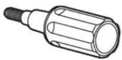

text_image
x 1 x 1x 1
text_image
Diagram illustrating a tool and its application, showing a screwdriver with cross symbol and a wrench extending to a hexagonal nut.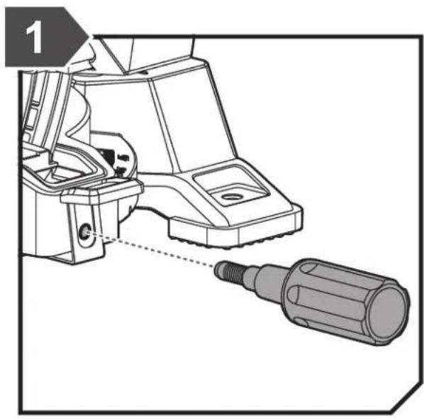
natural_image
Technical line drawing of a mechanical device with a cylindrical component inserted, showing no text or symbols.
text_image
2 1 2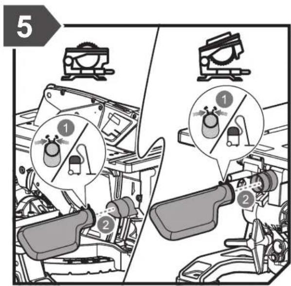
text_image
5 1 2 1 2
text_image
6 A B
text_image
3 1 2
text_image
4 iA

natural_image
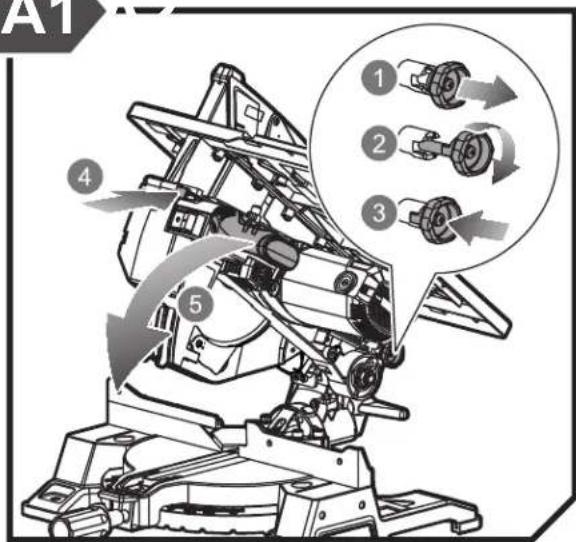
Simple line drawing of a mechanical device with a gear and handle (no text or symbols)A1
text_image
A1 ① ② ③ ④ ⑤

text_image
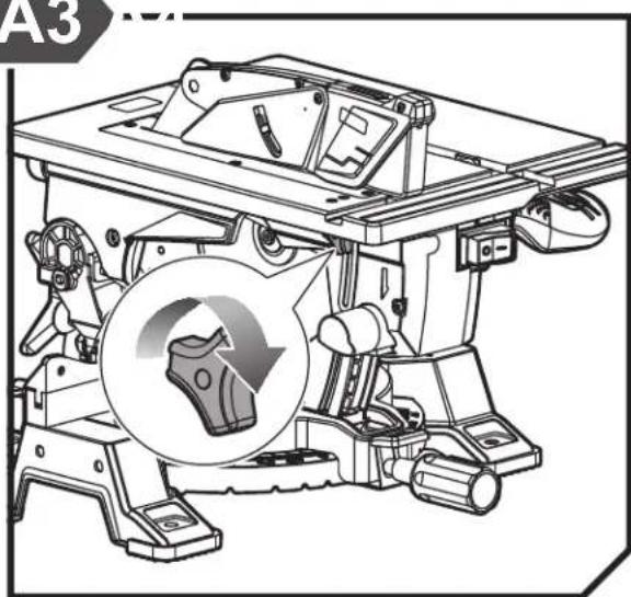
Technical diagram of a mechanical device with labeled parts and directional arrows indicating motion or assembly.A3
natural_image
Technical line drawing of a mechanical device with a circular inset showing a gear mechanism (no text or symbols)

text_image
Technical diagram of a mechanical assembly with labeled parts and directional arrows indicating flow or movement.B

natural_image
Simple line drawing of a microscope with no text or symbolsB1

text_image
Technical diagram of a mechanical assembly with labeled components and motion arrows indicating rotation or movement.

text_image
Technical diagram of a mechanical device with labeled parts and circular annotations indicating rotation and safety symbols.B3

text_image
B3 ① ② ③ ④
text_image
Technical diagram of a robotic device with numbered components and directional arrows indicating motion or assembly.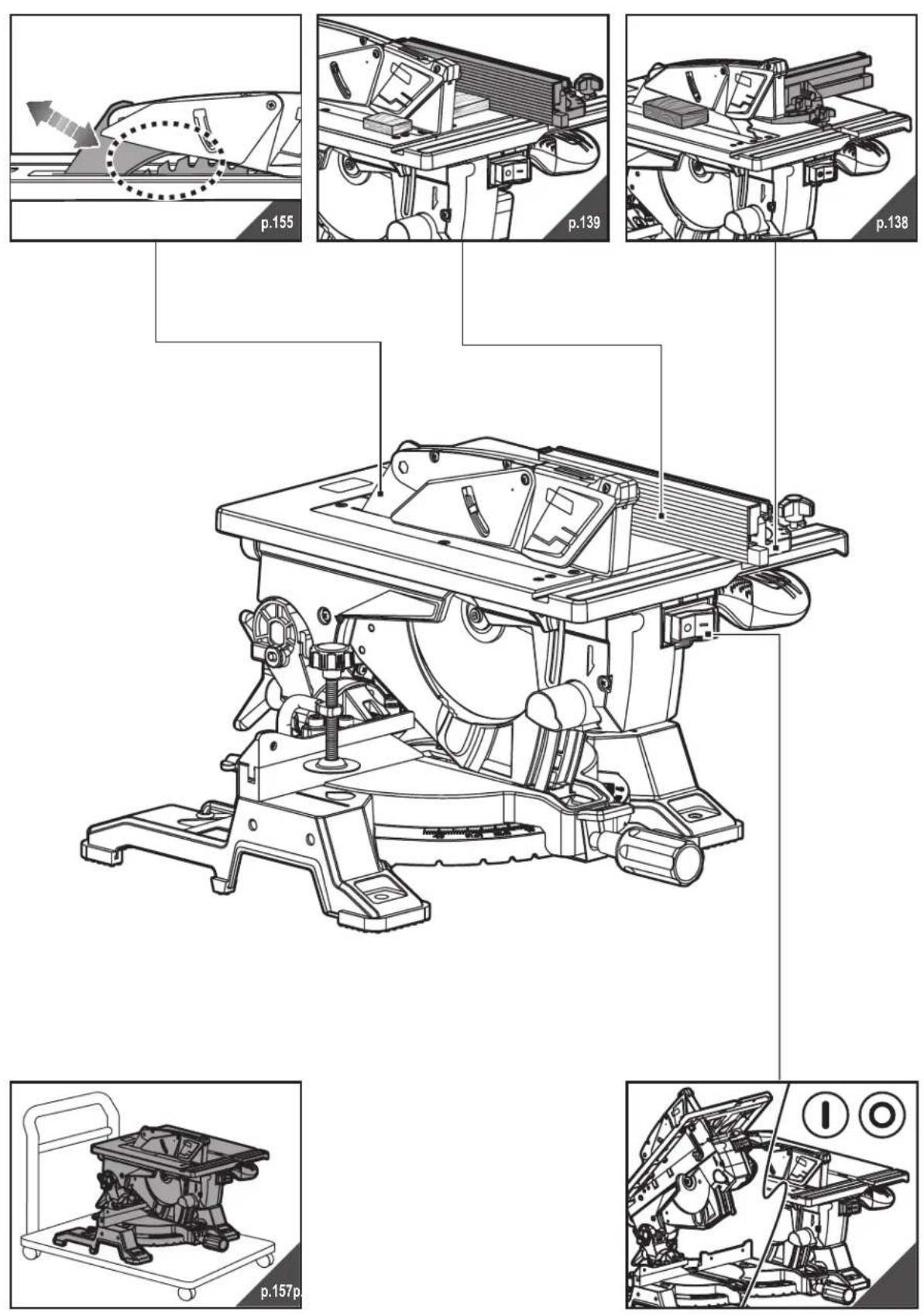


text_image
90°-90° p.15p. 90°-90° p.149p. 45°
natural_image
Technical line drawing of a mechanical device with no visible text or symbols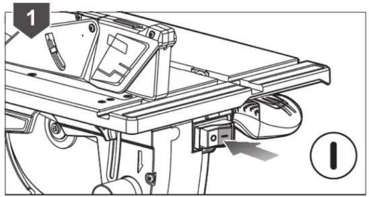
natural_image
Technical line drawing of a mechanical assembly with no visible text or symbols
natural_image
Technical line drawing of a mechanical assembly with no visible text or symbols
natural_image
Technical line drawing of a mechanical assembly with no visible text or symbols
natural_image
Technical line drawing of a mechanical assembly with no visible text or symbols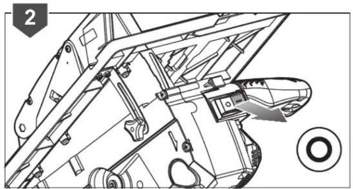
natural_image
Technical line drawing of a mechanical assembly with no visible text or symbols
natural_image
Technical line drawing of a mechanical assembly with no visible text or symbols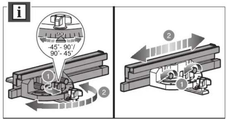
text_image
-45° - 90°/ 90° - 45° 1 2 1 2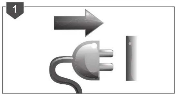
natural_image
Illustration of a plug and a vertical line with an arrow, no text or symbols present
text_image
Technical diagram showing mechanical assembly with labeled components and directional arrows indicating motion or assembly steps
text_image
Technical diagram of a mechanical assembly with numbered components and directional arrows indicating motion or flow.
natural_image
Technical line drawing of a mechanical assembly with no visible text or symbols
text_image
Technical diagram showing mechanical assembly steps with labeled components and directional arrows
text_image
Diagram showing electrical plug and switch components with numbered annotations indicating parts of the device.
text_image
Technical diagram showing mechanical assembly with checkmark and cross symbols indicating failure or rejection states
text_image
Technical diagram of a mechanical assembly with numbered components and directional arrows indicating motion or flow.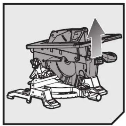
natural_image
Mechanical assembly diagram showing a cutting machine with an upward arrow indicating motion (no text or symbols present)
text_image
1 2 3 4 1
natural_image
Mechanical assembly diagram showing a rotating machine with a curved arrow indicating motion (no text or symbols present)
natural_image
Mechanical assembly diagram showing a motor or gear mechanism with a downward arrow indicating motion (no text or symbols present)
text_image
1 2 3
text_image
2 ① ②
natural_image
Technical line drawing of a mechanical device with no visible text or symbols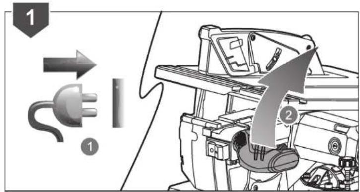
text_image
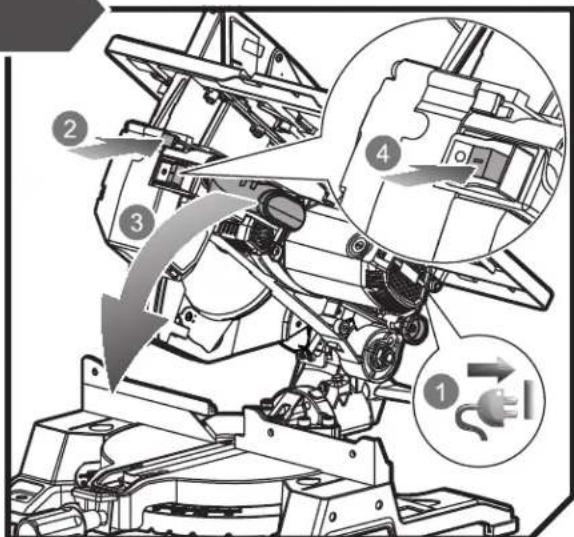
Diagram illustrating electrical plug and motor components with numbered annotations and directional arrows
natural_image
Technical line drawing of a mechanical assembly with no visible text or symbols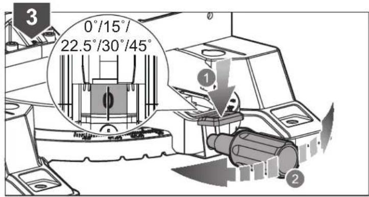
text_image
3 0°/15°/ 22.5°/30°/45° ① ②
natural_image
Technical diagram of a mechanical assembly with a cylindrical component and a curved arrow indicating motion (no text or symbols present)
natural_image
Mechanical assembly diagram showing a motor with rotating components and a directional arrow indicating motion (no text or symbols)
text_image
Diagram illustrating a power plug and motor assembly process with numbered annotations
natural_image
Technical line drawing of a mechanical assembly with no visible text or symbols
text_image
3 0°/15°/ 22.5°/30°/45° 1 2
natural_image
Technical line drawing of a mechanical assembly with a cylindrical component and housing (no text or symbols)
text_image
5 1 2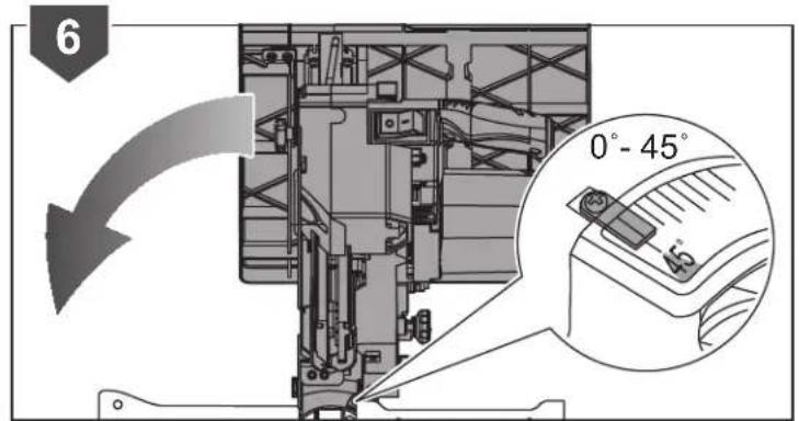
text_image
6 0° - 45° -5°
natural_image
Mechanical assembly diagram showing a bracket and gear mechanism (no text or labels)
text_image
8 1 2
text_image
9 ① ② ③
text_image
10 10s ① ②
natural_image
Technical line drawing of a mechanical assembly with gears and components (no text or symbols)
natural_image
Technical line drawing of a mechanical instrument with no visible text or symbols


natural_image
Technical line drawing of a mechanical device with an inset showing a button or switch (no text or symbols present)
text_image
2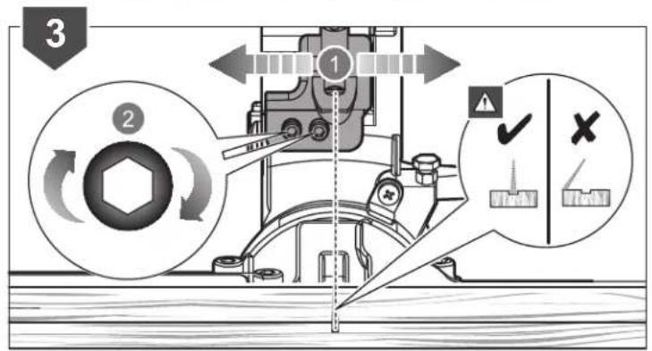
text_image
3 1 2 ✓ × U/Thx U/Thx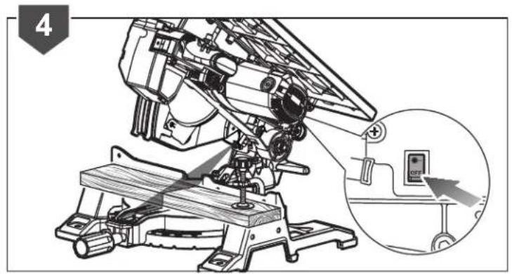
text_image
4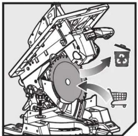
natural_image
Mechanical device diagram showing gear and waste disposal with recycling symbol (no text or labels)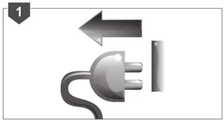
natural_image
Illustration of a plug with a cable and directional arrows, no text or symbols present
text_image
Technical diagram illustrating vehicle gear assembly and component inspection steps with numbered annotations
text_image
3 1 2 3 4
natural_image
Mechanical assembly diagram showing a machine with rotating components and a curved arrow indicating motion (no text or symbols)
text_image
5 ① ② ③ i x
text_image
Diagram illustrating a waste sorting machine with labeled components and directional arrows indicating process flow.
text_image
Diagram illustrating the mechanical assembly of a vehicle with labeled parts and directional arrows indicating components.
text_image
8 1 2
natural_image
Technical line drawing of a mechanical device with a 90-degree angle label (no readable text or symbols beyond the angle marker)
text_image
Diagram illustrating electrical plug and motor components with labeled parts 1 and 2, showing directional arrows and component layout.
text_image
2 0° 1 2
natural_image
Mechanical assembly diagram showing a piston and housing component with a rotating arrow (no text or symbols)
text_image
4 Hybrid 20 Hybrid 20
text_image
5 90 12.5 12.4 13
text_image
6 Inversion 25 Inversion 187-25
text_image
90°90°
text_image
Diagram illustrating a mechanical device with labeled parts and directional arrows, showing components like plug, switch, and motor assembly.
text_image
2 0° 1 2
natural_image
Mechanical assembly diagram showing a motor and gear assembly (no text or symbols)
text_image
4 ① ②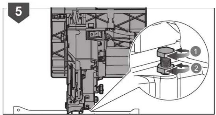
text_image
5 ① ②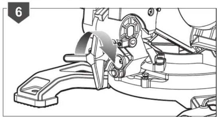
natural_image
Mechanical assembly diagram showing a lever mechanism with no visible text or symbols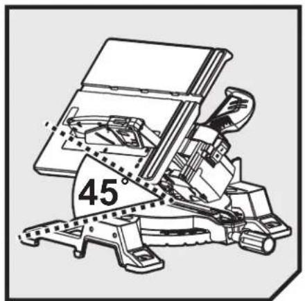
text_image
45°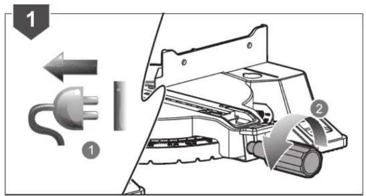
text_image
Diagram illustrating a mechanical assembly with labeled parts and directional arrows, showing components like a plug and motor.
text_image
2 0° 1 2
natural_image
Mechanical assembly diagram showing a motor and gear assembly (no text or symbols)
text_image
4 ① ②
text_image
5 1 2 45° =45° ≠45° 45°
natural_image
Mechanical assembly diagram showing a bracket and mounting bracket assembly (no text or labels)

natural_image
Diagram showing a mechanical component with an arrow indicating direction and a dotted circle highlighting a specific area (no text or symbols present)
text_image
Diagram illustrating a mechanical device with labeled parts and directional arrows indicating process flow
text_image
2 1 2 3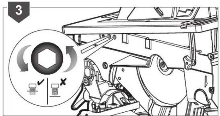
text_image
3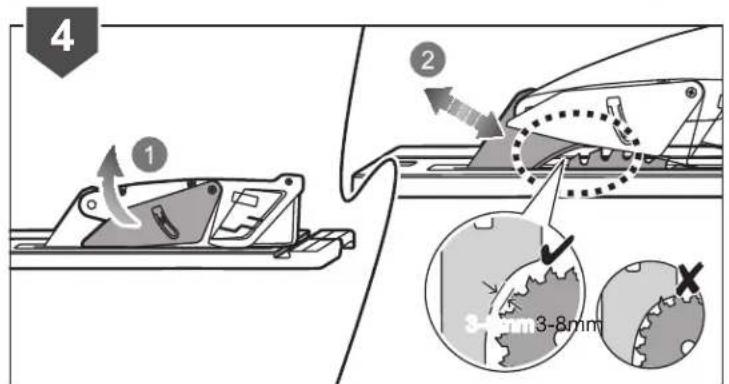
text_image
4 ① ② 3-8mm 3-8mm
natural_image
Line drawing of a mechanical device with wheels and a central frame (no text or symbols)
text_image
Technical diagram showing a plug and motor assembly with numbered components and directional arrows indicating flow or movement.
text_image
2 1 2 3
text_image
Technical diagram of a vehicle suspension system with labeled components and directional arrows indicating motion or movement.
flowchart
graph TD
    A["Hand gesture 1"] --> B["Hand gesture 2"]
    B --> C["Robot on cart with checkmark indicating safety check"]
    style A fill:#f9f,stroke:#333
    style B fill:#ccf,stroke:#333
    style C fill:#cfc,stroke:#333
20140618v2
English Français Deutsch Español Italiano Nederlands
| Product specifications | Caractéristiques de l'appareil | Produkt-Spezifikationen | Especificaciones del producto | Specifiche prodotto | Productspecificaties |
| Net weight Poids net Nettogewicht | Peso neto Peso neto Nettogewicht | ||||
| Blade diameter | Diamètre du disque de coupe | Sägeblattdurchmesser | Diâmetro de la hoja | Diametro lama | Zaagbladdiameter |
| Arbor hole | Trou de broche | Mittelloch | Hueco del eje | Foro dell'albero | Centergat |
| Blade teeth | Nombre de dents | Sägezähne | Dientes de la hoja | Denti lame | Zaagbladtanden |
| Width of cut | Largeur de coupe | Breite des Schnitts | Ancho del corte | Ampiezza di taglio | Maalbreedte |
| No-load speedr/min. (RPM) | Vitesse à videtr/min. (tr.min-1) | LeerlaufdrehzahlU/min | Velocidad sin cargar/min. (RPM) | Velocità a vuotornmin. (RPM) | Onbelast toerentalt/min. (TPM) |
| Input | Alimentation | Eingangsleistung | Cargador | Alimentazione | Input |
| Power | Puissance | Leistung | Potencia | Alimentazione | Vermogen |
| Dimension(L) x (W) x (H) | Dimensions(L) x (I) x (H) | Abmessungen(L) x (B) x (H) | Dimensiones(L) x (An) x (Al) | Dimensioni(L) x (A) x (A) | Afmetingen(L) x (B) x (H) |
| Cutting capacity(Mitre saw) | Capacité de coupe(Scie à onglet) | Schnittlichkeit(Gehrungssäge) | Capacidad de corte(Ingleadora) | Capacità di taglio(Sega per tagli obliqui) | Zaagcapaciteit(Verstekzaag) |
| Maximum workpiece crosssection | Section maximale de la pièceà couper | Maximaler Querschnitt desWerkstücks | Sección transversal máxima de lapieza de trabajo | Sezione massima del pezzosul quale si sta lavorando | Maximalewerkstukdoorsnede |
| 0° x 90° | 0° x 90° | 0° x 90° | 0° x 90° | 0° x 90° | 0° x 90° |
| 0° x 45° | 0° x 45° | 0° x 45° | 0° x 45° | 0° x 45° | 0° x 45° |
| 45° (L) x 90° | 45° (G) x 90° | 45° (L) x 90° | 45° (L) x 90° | 45° (L) x 90° | 45° (L) x 90° |
| 45° (R) x 90° | 45° (D) x 90° | 45° (R) x 90° | 45° (R) x 90° | 45° (R) x 90° | 45° (R) x 90° |
| 45° (L) x 45° | 45° (G) x 45° | 45° (L) x 45° | 45° (L) x 45° | 45° (L) x 45° | 45° (L) x 45° |
| 45° (R) x 45° | 45° (D) x 45° | 45° (R) x 45° | 45° (R) x 45° | 45° (R) x 45° | 45° (R) x 45° |
| Minimum size, workpiece | Dimensioni minime, pièce à usiner | Mindestgröße, Werkstück | Tamaño minimo, pieza trabajada | Dimensioni minime, pezzoda lavorare | Werkstukminimumafmeting |
| Cutting capacity(Table saw) | Capacité de coupe(Scie Circulaire sur Plateau) | Schnittlichkeit(Tischkreissäge) | Capacidad de corte(Sierra de mesa) | Capacità di taglio(Sega da tavolo) | Zaagcapaciteit(Tafelzaag) |
| Minimum size, workpiece | Dimensioni minime, pièce à usiner | Mindestgröße, Werkstück | Tamaño minimo, pieza trabajada | Dimensioni minime, pezzoda lavorare | Werkstukminimumafmeting |
| Maximum workpiececross-section | Section maximale de la pièceà couper | Maximaler Querschnitt desWerkstücks | Sección transversal máxima dela pieza de trabajo | Sezione massima del pezzosul quale si sta lavorando | Maximalewerkstukdoorsnede |
| Mitro cut | Onglet | Gehrung | Ingloto | Angolo | Verstok |
| Riving knife(thickness) | Couteau diviseur(apaisseur) | Spaltkeil(dicka) | Cuchilla(grosor) | Cuneo(spessore) | Spouwmes(dikto) |
| Dust extraction port diameter | Diamètre du conduit d'extractionde la scure | Durchmesser Anschluss derStaubabsaugung | Diâmetro de la puerta deextracción de polvo | Diâmetro porta di estrazionepolvere | Diameler stofextractiepoort |
| Mitro saw | Scie à onglet | Gehrungssäge | Inglotadora | Sega por tagli obliqui | Verstokzaag |
| Table saw | Scie Circulaire sur Plateau | Tischkreissäge | Sierra de mesa | Sega da tavolo | Tafelzaag |
| Minimum air speed(dust extraction port) | Vélocité minimale de l'air(conduit d'extraction de la scure) | Minimale Luftgeschwindigkeit(Anschluss der Staubabsaugung) | Velocidad minima del aire(puerta de extracción de polvo) | Velocità minima dell'aria(porta di estrazione polvere) | Minimum luchtsnelheid(stofextractiepoort) |
| Minimum air volume flow | Flux d'air minimum | Minimaler Luftvolumenstrom | Caudal de aire minimo | Flusso minimo dell'aria | Minimumluchtvolumestroom |
| Minimum vacuum flow | Flux d'aspiration minimum | Minimaler Vakuumstrom | Caudal minimo de aspirado | Flusso minimo aspiratore | Minimum vacuümstroom |
| Measured values determinedaccording to EN61029A-weighted sound pressurelevel | Valeurs mesurées obtenues selonEN61029Niveau de pression sonorepondéré-A | Gemäß EN61029 gemesseneWerteA-bewerteter Schalldruckpegel | Valores medidos determinados deacuerdo con EN61029Nivel de presión acústicanponderada en A | Valori misurati determinatiin accordo con lo standardEN61029Livello di pressione sonorapesato A | Valeurs mesurées obtenueselon EN61029A-gewogengeluidsdrukniveau |
| Uncertainty K | Incertitude K | Unsicherheit K | Incertidumbre K | Incertezza K | Onzekerheid K |
| Measured values determinedaccording to EN61029A-weighted sound power level | Valeurs mesurées obtenues selonEN61029Niveau de puissance sonorepondéré-A | Gemäß EN61029 gemesseneWerteA-bewerteter Schallleistungspegel | Valores medidos determinados daacuerdo con EN61029Nivel de potencia acústicanponderada en A | Valori misurati datarminatiin accordo con lo standardEN61029Livello di potenza sonorapesato A | Valeurs mesurées obtenueselon EN61029A-gewogen geluidsniveau |
| Uncertainty K | Incertitude K | Unsicherheit K | Incertidumbre K | Incertezza K | Onzekerheid K |
| The vibration total values(triaxial vector sum)determined according toEN 61029Vibration emission value(mitre saw mode only) | La valeur totale des vibrations(somme vectorielle triaxiale) a étédéterminée selon EN 61029Valeur d'émission de vibrations(Pour mode scie à ongletuniquement) | Die Vibrationsgesamtwerte(dreiaxiale Vektorsumme) wurdennach EN 61029Vibrationsemissionswert(Nur für Gehrungssäge-Modus) | Los valores totales de vibración(Suma vectorial triaxial) se handeterminado según la normaEN 61029Valor de emisión de vibraciones(Sólo para modo sierra de ingletes) | I valori di vibrazione totali(somma vettore triassiale)sono determinati secondo glistandard EN 61029Valore delle emissionivibrazioni(Solo per modalità sega pertagli obliqui) | De totale trillingswaarden(triaxiale vectorsom)werden vastgesteld inoveroenstomming metEN 61029Trillingsemissiewaarde(Uitsluitend voorverstekzaagmodus) |
| Uncertainty K | Incertitude K | Unsicherheit K | Incertidumbre K | Incertezza K | Onzekerheid K |


Português Dansk Svenska Suomi Norsk QllHygy
| Especificações do produto | Produktspecifikationer | Produktspecifikationer | Tuotteen tekniset tiedot | Produktpesifikasjoner | Характеристики изделия | |
| Peso líquido | Nettovægt | Nettovikt | Kokonalspaino | Nettovekt | Вес нетто | 15 kg |
| Diâmetro da lâmina=Klingodiameter=Klingdiameter=Terân lápimitta | Bladdiameter | Диаметр режущего диска | 254 mm | |||
| Orificio do eixo | Spindelhul | Spindelhål | Karan reikä | Spindelhull | Рабочее отверстие | 30 mm |
| Dentes da lâmina | Klingetænder | Sågtand | Terän hampaat | Bladtenner | Число зубьев | 48 |
| Largura do corte | Snitbredde | Skärbredd | Leikkauksen leveys | Bredde på kappet | Ширина разреза | 3 mm |
| Velocidade em vazio r/min. (RPM) | Tomgangshastighed omdrmin. (RPM) | Tomgängshastighet v/min (varv per minut) | Tyhjäkäytinopeus kiem/min (RPM) | Hastighet ubelastet o/min. (RPM) | Скорость на холостом ходу обмин | 4,800 ± 10% |
| Admissão | Stremforsyning | Matningsspänning | Virrankulutus | Input | Питание | 220V - 240V ~ 50 Hz |
| Potência | Effekt | Ström | Teho | Effekt | Мощность | 1,800 W |
| Dimensão(C) x (L) x (A) | Dimensão(C) x (L) x (A) | Dimensão(C) x (L) x (A) | Dimensão(C) x (L) x (A) | Dimensão(C) x (L) x (A) | Dimensão(C) x (L) x (A) | 565 x 555 x 445 mm |
| Capacidade do corte(Serra de esquadria) | Savekapacitet(Geringssav) | Skärkapacitet(Geringssåg) | Leikkuukapasitaetti(Vlistesaha) | Sagekapasitet(Gjærsag) | Режущая способность(Торщово-усовочная пила) | |
| Secção transversal máxima da peça de trabalho | Max emnetværsnit | Tvårsnitt maximum arbetsstycke | Työkappaleen suurin sallittu halkaisija | Krysseksjon for maksimum arbeidsstykke | Максимальное поперечное сечение заготовки | |
| 0^ × 90^ | 0^ × 90^ | 0^ × 90^ | 0^ × 90^ | 0^ × 90^ | 0^ × 90^ | 70 x 130 mm |
| 0^ × 45^ | 0^ × 45^ | 0^ × 45^ | 0^ × 45^ | 0^ × 45^ | 0^ × 45^ | 48 x 130 mm |
| 45^ (L) x 90^ | 45^ (G) x 90^ | 45^ (L) x 90^ | 45^ (L) x 90^ | 45^ (L) x 90^ | 45^ (лево) x 90^ | 70 x 85 mm |
| 45^ (R) x 90^ | 45^ (D) x 90^ | 45^ (R) x 90^ | 45^ (R) x 90^ | 45^ (R) x 90^ | 45^ (вправо) x 90^ | 70 x 64 mm |
| 45^ (L) x 45^ | 45^ (G) x 45^ | 45^ (L) x 45^ | 45^ (L) x 45^ | 45^ (L) x 45^ | 45^ (лево) x 45^ | 48 x 38 mm |
| 45^ (R) x 45^ | 45^ (D) x 45^ | 45^ (R) x 45^ | 45^ (R) x 45^ | 45^ (R) x 45^ | 45^ (вправо) x 45^ | 48 x 83 mm |
| Tamanho mínimo, peça a trabalhar | Minimumsstarrelse, arbejdsslykke/Emne | Minsta storlek, arbetsstycke | Minimikoko, lyökappale | Minimumstarrelse, arbeidsstykke | Минимальный размер, заготовка | 130 x 35 x 2.5 mm |
| Capacidade de corte(Serra de Mesa) | Savekapacitet(Bordsav) | Skärkapacitet(Bordsåg) | Leikkuukapasitaetti(Pyörsaha) | Sagekapasitet(Bordsag) | Режущая способность(Отрезной станок со столом) | |
| Tamanho mínimo, peça a trabalhar | Minimumsstarrelse, arbejdsslykke/Emne | Minsta storlek, arbetsstycke | Minimikoko, lyökappale | Minimumstarrelse, arbeidsstykke | Минимальный размер, заготовка | 5 x 5 mm |
| Secção transversal máxima da peça de trabalho | Max emnetværsnit | Tvårsnitt maximum arbetsstycke | Työkappaleen suurin salilltu halkaisija | Krysseksjon for maksimum arbeidsstykke | Максимальное поперечное сечение заготовки | |
| Chanfro | Gering | Gering | Viiste | Gjaring | Скос | 37 mm |
| Lâmina separadora(aspossura) | Drive kniven(tykkalse) | Spaiktniven(tjocklek) | Halkaisuveitsi(paksuus) | Splitter(tykkelse) | Расклиивающий нож(толщина) | 2 mm |
| Diâmetro da porta de extracção de pó | Diameter støvudsugningsport | Diameter, dammutvinningsport | Pölynpoistoaukon halkaisija | Diameter støvuttrekksåpning | Диаметр отверстия выпуска пыли | |
| Serra de esquadria | Geringssav | Geringssåg | Viistosaha | Gjærsag | Торщово-усовочная пила | 37 mm |
| Serra de Mesa | Bordsav | Bordssåg | Pyörösaha | Bordsag | Отрезной станок со столом | 40 mm |
| Velocidade de ar mínima(porta de extracção de pó) | Min. luftthaghed(støvudsugningsport) | Minimum luftflödeshastighet(dammutvinningsport) | Ilman miniminopeus(pölynpoistoaukko) | Minimum luftthastighet(støvuttrekksåpning) | Минимальная скорость потока воздуха(отверстие выпуска пыли) | 20 m/s |
| Fluxo de volume de ar mínimo | Min. luftvolumenflow | Minimum luftflödeshastighet | Pienin limavirtaus | Minimum luftvolumgjennomstrømning | Минимальный объемный расход воздуха | 550 m ^2 h |
| Fluxo de vácuo mínimo | Min. vakuumflow | Minimum vacuumflöde | Suurin imuvirtaus | Minimum vakuumgjennomstrømning | Минимальное разрежение | 740 Pa |
| Valores medidos calculados de acordo com EN61029Nivel de pressão sonora ponderada A | Mälte værdier bestemmes i henhold til EN61029A-vægtet lydtryksniveau | Vården uppmätta enligt EN61029A-vägd ljudtrycksnivå | Mitatut arvot määritettyEN61029 -standardin mukaanA-painotettu äänenpainetaso | Mälte verdier i samsvar med EN61029A-vektet lydtrykknivå | Измеренные значения определены в соответствии с EN61029Уровень А-звешенного заукового давления | L_px = 94,5 dB(A) |
| Incerteza K | Usikkerhed K | Osäkerhet K | Epätarkkuus K | Usikkerhet K | Разброс К | 3 dB |
| Valores medidos calculados de acordo com EN61029Nivel de potência sonora ponderada A | Mälte værdier bestemmes i henhold til EN61029A-vægtet lydeffektniveau | Vården uppmätta enligt EN61029A-vägd ljudeffektsnivå | Mitatut arvot määritettyEN61029 -standardin mukaanA-painotettu äänenatoho | Mälte verdier i samsvar med EN61029A-vektet lydeffektnivå | Измеренные значения определены в соответствии с EN61029Уровень А-звешенной зауковой мощности | L_px = 108 dB(A) |
| Incerteza K | Usikkerhed K | Osäkerhet K | Epätarkkuus K | Usikkerhet K | Разброс К | 3 dB |
| Os valores totals de vibração(Soma vectorial triaxial) foram determinados de acordo com a norma EN 61029Valor de emissão de vibrações(Só para modo de serra circular) | De totale vibrationsværder (triaksial vektorsum) er bestemt i henhold til EN 61029Vibrationsemissionsværdi(Kun til geringsmodus) | De totala vibrationsvärderma(triaxial vektorsumma) bestáms enligt EN 61029Vibrationsvärde(Enbart för geringsläget) | Tärhän kokonaisarvot(kolmiakselinen vektorsumma)määrtottynä standardion EN 61029 mukalsestiTärinäarvo(Vain viistesahatilalle) | De totale vibrasjonsverdiene (treakset vektorsum) er i henhold til EN 61029Verdier for vibrasjonsutslipp (Kun for gjærings modus) | Суммарное значение вибрации (сумма векторов по трем координатным осям) определено в соответствии со стандартом EN 61029Значение вибрации(Tолько для режиме торцовочной пилы) | a_н = 1,6 m/s^2 |
| Incerteza K | Usikkerhed K | Osäkerhet K | Epätarkkuus K | Usikkerhet K | Разброс К | 1,5 m/s |


| Polski | Čeština | Magyar | Română | Latviski | Lietuviškai |
| Parametry techniczne | Technické údaje produktu | Termék műszaki adatai | Specificațiile produsului | Produkta specifikacijas | Gaminio techninés savybės |
| Masa netto Čistă hmotnost Nettó | tömeg Greutate netă Svars neto | Neto svoris | |||
| Średnica tarczy tnącej | Průměr kotouče | Tárcsa átmérójje | Diametru lamă | Asmens diamets | Pjovimo disko skersmuo |
| Otwór trzplenia | Otvor hřidele | Tengelyfurat | Orificiu arbore | Várpslas atvere | Ašies angă |
| Liczba zębow tarczy | Zub kotouče | Fürászlap fogai | Dinte lamă | Asmens zobi | Galežlės dantuku skaičius |
| Szerokość cięcia | Šírka řezu | Vágás szalessége | Lątjme a tâlerii | Griezuma platums | Pjovimo plotis |
| Prędkość bez obciążenia obr./min. (RPM) | Otǎcky naprázdno ot./min. (RPM) | Úrsjáratí fordulatszam ford./perc (RPM) | Vitază în gol rot/min. (RPM) | Apgriezioni bez siódzos apgr./min. (RPM) | Greitis be apkrovimo aps./min. (apsukų per minutę) |
| Zasilania | Vstup | Bemenet | Intrare | leeja | Ivastis |
| Moc | Výkon | Teljesítmény | Alimentare | Strava | Galia |
| Wymiar (dl.) x (szer.) x (wys.) | Rozměry (D)X(Š)X(V) | Méret (H) x (SZ) x (M) | Dimensiuni (L) x (I) x (H) | Izměri (G) x (P) x (A) | Matmenys (L) x (W) x (H) |
| Zakres możliwości cięcia (Pilarka ukosowa) | Maximalní prořez (Pokosová pila) | Vágásteljesítmény (Gérvágó fürész) | Capacitate de taliere (Ferăstrâu unghiular) | Zágõšanas raziba (Lenjzágis) | Pjovimo talpa (Škersinis pjúklas) |
| Maks. przekrój obrabianego materiału | Maximalní přičný řez obrobku | Maximalís munkadarab-karesztmetszot | Secjune transversală maximă a piesei de prelucrat | Maksimalais detajas škarsgriezums | Didžausia pjaunamo objekto skarsinė dalis |
| 0° x 90° | 0° x 90° | 0° x 90° | 0° x 90° | 0° x 90° | 0° x 90° |
| 0° x 45° | 0° x 45° | 0° x 45° | 0° x 45° | 0° x 45° | 0° x 45° |
| 45° (L) x 90° | 45° (L) x 90° | 45° (B) x 90° | 45° (S) x 90° | 45° (kreisais) x 90° | 45° (kaire) x 90° |
| 45° (R) x 90° | 45° (P) x 90° | 45° (J) x 90° | 45° (D) x 90° | 45° (labais) x 90° | 45° (desinė) x 90° |
| 45° (L) x 45° | 45° (L) x 45° | 45° (B) x 45° | 45° (S) x 45° | 45° (kreisais) x 45° | 45° (kaire) x 45° |
| 45° (R) x 45° | 45° (P) x 45° | 45° (J) x 45° | 45° (D) x 45° | 45° (labais) x 45° | 45° (desinė) x 45° |
| Minimalny rozmiar, przedmiot do obrobki | Minimalní rozměr, obráběný materiál | Minimális méret, munkadarab | Mărime minimă, piesă de prelucrat | Minimalais izměrs, sagatave | Mažiausias dydis, Ruošinys |
| Zakres możliwości cięcia (Pilarka stolowo-tarczowa) | Maximalní prořez (Stolová pila) | Vágásteljesítmény (Asztali kõrtürész) | Capacitate de taliere (Ferăstrâu circular cu masă) | Zágõšanas raziba (Galda zágis) | Pjovimo talpa (Pjovimo staklės) |
| Minimalny rozmiar, przedmiot do obrobki | Minimalní rozměr, obráběný materiál | Minimális méret, munkadarab | Mărime minimă, piesă de prelucrat | Minimalais izměrs, sagatave | Mažiausias dydis, Ruošinys |
| Maks. przekrój obrabianego materiału | Maximalní přičný řez obrobku | Maximalís munkadarab-keresztmetszot | Secjune transversală maximă a piesei de prelucrat | Maksimalais detajas škyersgriezums | Didžausia pjaunamo objekto skersinė dalis |
| Ukos | Pokos | gérvágás | Înclinare pe orizontala | Griezuma lenjis | Kreiptuvas |
| Klin rozszczepiający (grubość) | Štípaci klin (tlouštka) | Hasítókés (vastagság) | Cultul de despicare (grosime) | Šyšełejnazis (biezums) | Skaldomasis pelis (storumas) |
| Środnica otwortu odpylania | Průměr připojky lapače prachu | Porelszivó nyllas atmérője | Diametru port de extragero praf | Putełku ekstrakcijas porta diameters | Dulkių istraukimo angos skersmuo |
| Pilarka ukosowa | Pokosová pila | Gérvágó fürész | Ferăstrâu unghiular | Lenjzágis | Skersinis pjúklas |
| Pilarka stolowo-tarczowa | Stolová pila | Asztali körtürész | Ferăstrâu circular cu masă | Galda zágis | Pjovimo staklės |
| Min. prędkość powietrza (gniazdo odpylania) | Minimální rychlost vzduchu (pripojka lapače prachu) | Minimális légsebesség (porelszívó nyllas) | Vitază minimă a aerului (port de extragero a prafului) | Minimalais gaisa žirums (putoklu ekstrakcijas ports) | Mažiausias oro greitis (dulkių istraukimo angojo) |
| Min. przepływ powietrza | Minimální objem protećeného vzduchu | Minimális légtömegáramlás | Debit minim de aer | Minimalá gaisa apjoma plósmá | Mažiausia oro klekio tékmé |
| Min. przepływ próżni | Minimální objem odsávaného vzduchu | Minimális szlivó áramlás | Debit minim de aspirare | Minimalá vakuuma plósmá | Mažiausia vakuumo tékmé |
| Zmierzone wartości określone wg EN61029 | Namřené hodnoty zjištěné dle EN61029Hladina akustického tlaku važena funkcí A | A mért értékek meghatározása az EN61029 szerint töránent A-súlyozot hangnyomásszint | Valori másurate determinate în conformitate cu EN61029Nivel de presiune acustică ponderată A | Izměritás vertības saskaņa ar EN61029A-līmena skanąs spiediena Ilmenis | Išmatuotosios vertės nustatytos pagal EN61029A svertinis garso silógio lygis |
| Niepewność pomiaru K | Nejistola K | Bizonytalanság K | Incertitudine K | Kjūdas vērtība K | Nepastovumas K |
| Wartości sumaryczne drgań (suma weiktora trjōsiowego) określone zgodnia z norma EN61029Poziom drgań | Celkové hodnoty vibraci (Trojosý vektorovy součet) určené v souladu s EN61029Üroveň emisi vibraci | A vibració teljes értékei (háromtengelyú vektorösszeg), az EN61029 szerint meghatározva.Vibració-kibocsátás értéke | Valorite totale ale vibratjilor (sumă vector triaxială) au fost determinate în conformitate cu EN61029Valoarea emisilior de vibrajii | Vibracijas kopėjās vērtības (tnaksială vektoru summa) ir notoktas abilstosi EN61029Vibraciju emisijas vērtība | Bendros vibracijos vertės (triasião vektoriaus suma)nustatomos pagal EN61029Vibracijos emisijos vertė |
| Niepewność pomiaru K | Nejistola K | Bizonytalanság K | Incertitudine K | Kjūdas vērtība K | Nepastovumas K |
| Wartości sumaryczne drgań (suma weiktora trjōsiowego) określone zgodnie z norma EN 61029Poziom drgań (Tylko dla tryble pily-grzbietnicy) | Celkové hodnoty vibraci (Trojosý vektorovy součet) určené v souladu s EN 61029Üroveň emisi vibraci (Pouze pro režim pokosové pily) | A vibració teljes értékei (háromtengelyú vektorösszeg), az EN 61029 szerint meghatározva.Vibració-kibocsátás értéke(Csak gérvágó fürész üzemmódhoz) | Valorite totale ale vibratjilor (sumă vector triaxială) au fost determinate în conformitate cu EN 61029Valoarea emisilior de vibrajii(Doar pentru modul ferăstrâu unghiular) | Vibracijas kopėjās vērtības (tnaksială vektoru summa) ir notoktas abilstosi EN 61029Vibraciju emisijas vērtība(Tikai lenjzága režimam) | Bendros vibracijos vertės (triasião vektoriaus suma)nustatomos pagal EN 61029Vibracijos emisijos vertė(Tik pičkią nuozambaus pjovimo režimu) |
| Niepewność pomiaru K | Nejistola K | Bizonytalanság K | Incertitudine K | Kjūdas vērtība K | Nepastovumas K |
| Eesti Hrvatski Slovensko Slovenčina Ελληνικά Türkçe | ||||||
| Toote tehnilised andmed | Specifikacije proizvoda | Specifikacije izdelka | Špedifikácia | Προδιαγραφός Προϊόντος | Ürün Özellikleri | |
| Netomass | Neto težina | Neto teža | Hmotnost | Καθαρό βάρος | Net ağırlık | 15 kg |
| Saeketta läbimõõt | Promjer rezne ploče=Premer rezila | Priemer kotuča | Διάμετρος λεπίδας | Βιçak çapı | 254 mm | |
| Völliava | Otvor za vratilo | Izvrtina vretena | Otvor hriadefa | Οπή άξονα | Mil deligi | 30 mm |
| Lõiketera hammas | Zubi pile | Zobje rezila | Zübky čepele | Δόντια λεπίδας | Βιçak dişleri | 48 |
| Lõikelalus | Širina reza | Širina rezanja | Širka rezu | Πλάτος κοπής | Kesim genişliği | 3 mm |
| Klirus lima koormuseta p/min. (p/min) | Brzina bez optarečanja o/min (OKR/MIN) | Hitrost brez obremenitive vrt./min (RPM) | Otáčky bez zafaženia ot./min. | Ταύπητα στ κεν τίmin. (RPM) | Bota hiz didak. (DDS) | 4,800 ± 10% |
| Vooluvörk | Ulaz | Vhod | Vstup | Είποδος ρεύματος | Giriş | 220V - 240V ~ 50 Hz |
| Võimsus | Napajanje | Napajanje | Napajanie | Ισχύς | Güç | 1,800 W |
| Mõõtmed (L) x (W) x (H) | Dimenzje (D) x (Š) x (V) | Mere (D) x (Š) x (V) | Rozmery (D) x (Š) x (V) | Διαστάσεις (M) x (Π) x (Y) | Ebat (U) x (G) x (Y) | 565 x 565 x 445 mm |
| Lõikesügavus (Milusaag) | Kapacitet rezanja (Kutna pila) | Zmogljivost rezanja (Zajeraina žaga) | Kapacita rezania (Rozbrusovačka) | Ικανότητα κοπής (Κόπης για φολισογωνιες) | Kesim kapasitesi (Gönye testeresi) | |
| Tooriku maksimaalne ristlõige | Maksimalna poprečna duljina izratka | Maksimalni presek obdelovanca | Maximalny prierez obročku | Μέγιση διατομή τεμαχίου εργαστίας | Çalışma malzemesi maksimum çapraz kesiti | |
| 0° x 90° | 0° x 90° | 0° x 90° | 0° x 90° | 0° x 90° | 0° x 90° | 70 x 130 mm |
| 0° x 45° | 0° x 45° | 0° x 45° | 0° x 45° | 0° x 45° | 0° x 45° | 48 x 130 mm |
| 45° (L) x 90° | 45° (L) x 90° | 45° (L) x 90° | 45° (L) x 90° | 45° (L) x 90° | 45° (Sol) x 45° | 70 x 85 mm |
| 45° (R) x 90° | 45° (D) x 90° | 45° (R) x 90° | 45° (R) x 90° | 45° (R) x 90° | 45° (Sağ) x 90° | 70 x 64 mm |
| 45° (L) x 45° | 45° (L) x 45° | 45° (L) x 45° | 45° (L) x 45° | 45° (L) x 45° | 45° (Sol) x 90° | 48 x 38 mm |
| 45° (R) x 45° | 45° (D) x 45° | 45° (R) x 45° | 45° (R) x 45° | 45° (R) x 45° | 45° (Sağ) x 45° | 48 x 83 mm |
| Minimaalne mööt, toorik | Minimalna veličina, komad koji se obrađuje | Minimalna velikost, obdelovanec | Minimalna veľkost, obrobok | Ελάχιστο μέγεῖος, προς επεξργαστία αντικείμενα | Minimum ebat, üzerinde çalışılacak malzeme | 130 x 35 x 2.5 mm |
| Lõikesügavus (Milusaag) | Kapacitet rezanja (Kutna pila) | Zmogljivost rezanja (Zajeraina žaga) | Kapacita rezania (Rozbrusovačka) | Ικανότητα κοπής (Κόπης για φολισογωνιεс) | Kesim kapasitesi (Gönye testeresi) | |
| Minimaalne mööt, toorik | Minimalna veličina, komad koji se obrađuje | Minimalna velikost, obdelovanec | Minimalna veľkost, obrobok | Ελάχιστο μέγεῖος, προς επεξργαστία αντικείμενα | Minimum ebat, üzerinde çalışılacak malzeme | 5 x 5 mm |
| Tooriku maksimaalne ristlõige | Maksimalna poprečna duljina izratka | Maksimalni presek obdelovanca | Maximalny prierez obrobku | Μέγιση διατομή τεμαχίου εργαστίας | Çalışma malzemesi maksimum çapraz kesiti (Testere tezgahi) | |
| Kaldölge | Kutna ploča | Poševna miza | Sklon | Φαλτοσγυνια | Gönye | 37 mm |
| Lõhestusnuga (paksus)=Razdejelnik (debijlna)=Cepilni no2 (debellina) | Rozovieraci klin (hrůbka) | Θραώστης (τιάχος) | Yarma bicağı (kalinlik) | 2 mm | ||
| Tolmuärastusctsaku läbimööt | Promjer izlaza za izbacivanje prasine | Premier izhoda za odvajanje prahu | Priemer kanála na odsávanie prachu | Διάμετρος θύρας απομάκρυνσης πριονιδιού | Toz çekme girişi çapı | |
| Miuisaag | Kutna pila | Zajeralna žaga | Rozbrusovačka | Κόπης για φαλισογωνιες | Gönye testeresi | 37 mm |
| Saepink | Stolna pila | Namizna žaga | Stolová pila | Επτραπεζίος Κόπης | Testere tezgahi | 40 mm |
| Öhu minimaalkirus (tolmuärastuscsak) | Maksimalna brzina zraka (Izlaz za izbacivanje prasine) | Maksimalna hitrost zraka (izhod za odvajanje prahu) | Maximalna rýchlosť vzduchu (kanál na odsávanie prachu) | Ελάχιστη ταχύητα αέρα (θύρα απομάκρυνσης πριονιδιού) | Minimum hava akış hızı (toz çekme girişi) | 20 m/s |
| Öhu minimaalne vooluhulk | Maksimalni volumen protoka zraka | Minimalni pretok zraka | Maximalny objemový prietok vzduchu | Ελάχιστη ποή ογκου αέρα | Minimum hava akış hacmi | 550 m³/h |
| Vaakumi minimaalne vooluhulk | Maksimalni protok vakuuma | Minimalni sesalni pretok | Minimalny vákurový prietok | Ελάχιστη ποή κενού | Minimum vakum akışı | 740 Pa |
| Mõõseväartused on kindlaks määratud vastavalt standardite EN61029 A-kaalutud halirõhu tase | Mjerene vrijednosti određene su prema EN61029 Ponderirana razina tlaka zvuka | Izmerjene vrednosti določene v skladu s standardom EN61029 A-izmerjona raven zvočnega tlaka | Namerané hodnoty určené podľa VAžená A hladina akustického tlaku | Οι υπολογικτιμένες τιμές καθορίστηκαν σύμφωνα με το EN61029 A-σταθμικτιμένο επίπεδο πίεσης ήχου | EN61029 lle uyumlu olarak belirlenen όζülen degeler A ağırlıklı ses basınç seviyesi | L_ = 94,5 dB(A) |
| Mõötemääramatus K | Neodređenost K | Nedoloč. K | Odchýlka K | Αβεβαιότητα K | Belirsizlik K | 3 dB |
| Vibratsiooni üldväärtus (kolme suuna vektorsumma) on kindlaks määratud vastavalt standardite EN61029 Vibratsioonlemissiooni viärtus | Ukupne vrijednosti vibracija (troosovinski vektorski zbroj) određuje se u skladu s EN61029 Vrijednost emisija vibracije | Efektivna vrednost vibracij (triaksialna vektorska vsota) določena v skladu z EN61029 Vrednost emisij vibracij | Celkové hodnoty vibrácií (priestorový vektorový sučet) stanovené podľa noriem EN61029 Hodnota emisii vibrácií | Οι συνολικές τιμές κραδασμών (τριαόνικα διανυσματικό άθροισμαί καθορίστηκαν σύμφωνα με τα EN61029 Τιμή εκτομπών κραδασμών | Titreşim toplam değerleri (üüksenli vektör toplami) EN61029 standartlarına göre balirlenmiştir. Titreşim emisyon değerli | L_ = 108 dB(A) |

EN WARNING
The vibration emission level given in this information sheet has been measured in accordance with a standardised test given in EN 61029-2-9 and may be used to compare one tool with another. It may be used for a preliminary assessment of exposure. The declared vibration emission level represents the main applications of the tool. However if the tool is used for different applications, with different accessories or poorly maintained, the vibration emission may differ. This may significantly increase the exposure level over the total working period.
An estimation of the level of exposure to vibration should also take into account the times when the tool is switched off or when it is running but not actually doing the job. This may significantly reduce the exposure level over the total working period. Identify additional safety measures to protect the operator from the effects of vibration such as: maintain the tool and the accessories, keep the hands warm, organisation of work patterns.
FR AVERTISSEMENT
In addition to any statutory rights resulting from the purchase, this product is covered by a guarantee as stated below.
- The guarantee period is 24 months for consumers and commences on the date when the product was purchased. This date has to be documented by an invoice or other proof of purchase. The product is designed and dedicated to consumer and private use only. So there is no guarantee provided in case of professional or commercial use.
- There is, in some cases (i.e. promotion, range of tools), a possibility to extend the warranty period over the period described above using the registration on the www.ryobitools.eu website. The eligibility of the tool is clearly displayed in stores and/or on packaging. The end user needs to register his/her newly-acquired tools online within 8 days from the date of purchase. The end user may register for the extended warranty in his country of residence if listed on the online registration form where this option is valid. Furthermore, end users must give their consent to the storage of the data which are required to enter online and they have to accept the terms and conditions. The registration confirmation receipt, which is sent out by e-mail, and the original invoice showing the date of purchase will serve as proof of the extended warranty. Your statutory rights remain unaffected.
- The guarantee covers all defects of the product during the warranty period due to defaults in workmanship or material at the purchase date. The guarantee is limited to repair and/or replacement and does not include any other obligations including but not limited to incidental or consequential damages. The warranty is not valid if the product has been misused, used contrary to the instruction manual, or being incorrectly connected. This guarantee does not apply to:
– any damage to the product that is the result of improper maintenance
– any product that has been altered or modified
– any product where original identification (trade mark, serial number) markings have been defaced, altered or removed
– any damage caused by non-observance of the instruction manual
- any non CE product
– any product which has been attempted to be repaired by an non-qualified professional or without prior authorization by Techtronic Industries
– any product connected to improper power supply (amps, voltage, frequency)
– any damage caused by external influences (chemical, physical, shocks) or foreign substances
– normal wear and tear of spare parts
– inappropriate use, overloading of the tool
- use of non-approved accessories or parts
– carburettor after 6 months, carburettor adjustments after 6 months
- power tool accessories provided with tool or purchased separately. Such exclusions include but is not limited to screw driver bits, drill bits, abrasive discs, sand paper and blades, lateral guide
- components (parts and accessories) subject to natural wear and tear, including but not limited to carbon brushes, chuck, power cord, auxiliary handle, sanding plate, dust bag, dust exhaust tube
-
For servicing, the product must be sent or presented to a RYOBI authorized service station listed for each country in the following list of service station addresses. In some countries your local RYOBI dealer undertakes to send the product to the RYOBI service organisation. When sending a product to a RYOBI service station, the product should be safely packed without any dangerous contents such as petrol, marked with sender's address and accompanied by a short description of the fault.
-
A repair/replacement under this guarantee is free of charge. It does not constitute an extension or a new start of the guarantee period. Exchanged parts or tools become our property. In some countries delivery charges or postage will have to be paid by the sender.
-
This guarantee is valid in the European Community, Switzerland, Iceland, Norway, Liechtenstein, Turkey and Russia. Outside these areas, please contact your authorized RYOBI dealer to determine if another warranty applies.
AUTHORISED SERVICE CENTRE
To find an authorised service centre near you, visit http://www.ryobitools.eu/service-support/service-agents.
FR GARANTIE
EC DECLARATION OF CONFORMITY
Techtronic Industries GmbH
Max-Eyth-Straße 10, 71364 Winnenden, Germany
Herewith we declare that the product
Table Mitre Saw
Brand: Ryobi
Model number: RTMS1800
Serial number range: 44424901000001 - 44424901999999
is in conformity with the following European Directives and harmonised standards 2006/42/EC, 2004/108/EC, 2011/65/EU
EN55014-1:2006+A1:2009+A2:2011; EN55014-2:1997+A1:2001+A2:2008;
EN61000-3-2:2006+A1:2009+A2:2009; EN61000-3-3:2008;
EN 61029-1:2009+A11:2010; EN 61029-2-11:2012+A11:2013
Notified body No. 2140 has carried out EC type approval, and the certificate No. is 4812015.14001.

Andrew John Eyre (BEng, CEng, MIET)
Vice President, Regulatory & Safety
Winnenden, Mar. 18, 2014
Authorised to compile the technical file:
Alexander Krug, Managing Director
Techtronic Industries GmbH
Max-Eyth-Straße 10, 71364 Winnenden, Germany

DÉCLARATION DE CONFORMITÉ EC
Techtronic Industries GmbH
Max-Eyth-Straße 10, 71364 Winnenden, Germany
Winnenden, Mar. 18, 2014
Max-Eyth-Straße 10, 71364 Winnenden, Germany

Max-Eyth-Straße 10, 71364 Winnenden, Germany
Winnenden, Mar. 18, 2014
Max-Eyth-Straße 10, 71364 Winnenden, Germany

Max-Eyth-Straße 10, 71364 Winnenden, Germany
Winnenden, Mar. 18, 2014
Max-Eyth-Straße 10, 71364 Winnenden, Germany

Max-Eyth-Straße 10, 71364 Winnenden, Germany
Winnenden, Mar. 18, 2014
Max-Eyth-Straße 10, 71364 Winnenden, Germany

EC CONFORMITEITSVERKLARING
Techtronic Industries GmbH
Max-Eyth-Straße 10, 71364 Winnenden, Germany
Winnenden, Mar. 18, 2014
Max-Eyth-Straße 10, 71364 Winnenden, Germany


Max-Eyth-Straße 10, 71364 Winnenden, Germany
Winnenden, Mar. 18, 2014
Max-Eyth-Straße 10, 71364 Winnenden, Germany

EC OVERENSSTEMMELSESERKLAERING
Techtronic Industries GmbH
Max-Eyth-Straße 10, 71364 Winnenden, Germany
Vi erklærer hermed, at produktet
Kap- og geringssav
Brand: Ryobi
Modelnummer: RTMS1800
Serienummerområde: 44424901000001 - 44424901999999
Winnenden, Mar. 18, 2014
Max-Eyth-Straße 10, 71364 Winnenden, Germany

EC-KONFORMITETSDEKLARATION
Techtronic Industries GmbH
Max-Eyth-Straße 10, 71364 Winnenden, Germany
Winnenden, Mar. 18, 2014
Max-Eyth-Straße 10, 71364 Winnenden, Germany

EC-SÄÄNNÖSTEN NOUDATTAMINEN
Techtronic Industries GmbH
Max-Eyth-Straße 10, 71364 Winnenden, Germany
Winnenden, Mar. 18, 2014
Max-Eyth-Straße 10, 71364 Winnenden, Germany

EC-SAMSVARSERKLÆRING
Techtronic Industries GmbH
Max-Eyth-Straße 10, 71364 Winnenden, Germany
Winnenden, Mar. 18, 2014
Max-Eyth-Straße 10, 71364 Winnenden, Germany

Max-Eyth-Straße 10, 71364 Winnenden, Germany
Winnenden, Mar. 18, 2014
Max-Eyth-Straße 10, 71364 Winnenden, Germany
Winnenden, Mar. 18, 2014
Max-Eyth-Straße 10, 71364 Winnenden, Germany

PROHLÁŠENÍ O SHODĚ EC
Techtronic Industries GmbH
Max-Eyth-Straße 10, 71364 Winnenden, Germany
Winnenden, Mar. 18, 2014
Max-Eyth-Straße 10, 71364 Winnenden, Germany

EC MEGFELELÖSÉGI NYILATKOZAT
Techtronic Industries GmbH
Max-Eyth-Straße 10, 71364 Winnenden, Germany
Winnenden, Mar. 18, 2014
Max-Eyth-Straße 10, 71364 Winnenden, Germany
CE

DECLARATIE DE CONFORMITATE EC
Techtronic Industries GmbH
Max-Eyth-Straße 10, 71364 Winnenden, Germany
Winnenden, Mar. 18, 2014
Alexander Krug, Director General
Techtronic Industries GmbH
Max-Eyth-Straße 10, 71364 Winnenden, Germany

EC ATBILSTĪBAS DEKLARĀCIJA
Techtronic Industries GmbH
Max-Eyth-Straße 10, 71364 Winnenden, Germany
Winnenden, Mar. 18, 2014
Max-Eyth-Straße 10, 71364 Winnenden, Germany

EC ATITIKTIES PAREIŠKIMAS
Techtronic Industries GmbH
Max-Eyth-Straße 10, 71364 Winnenden, Germany
Winnenden, Mar. 18, 2014
Max-Eyth-Straße 10, 71364 Winnenden, Germany

EC VASTAVUSDEKLARATSIOON
Techtronic Industries GmbH
Max-Eyth-Straße 10, 71364 Winnenden, Germany
Kinnitame, et see toode
Winnenden, Mar. 18, 2014
Max-Eyth-Straße 10, 71364 Winnenden, Germany
CE

EC IZJAVA O USKLAĐENOSTI
Techtronic Industries GmbH
Max-Eyth-Straße 10, 71364 Winnenden, Germany
Winnenden, Mar. 18, 2014
Max-Eyth-Straße 10, 71364 Winnenden, Germany
CE

IZJAVA EC O SKLADNOSTI
Techtronic Industries GmbH
Max-Eyth-Straße 10, 71364 Winnenden, Germany
Winnenden, Mar. 18, 2014
Max-Eyth-Straße 10, 71364 Winnenden, Germany
CE

PREHLÁSENIE O ZHODE EC
Techtronic Industries GmbH
Max-Eyth-Straße 10, 71364 Winnenden, Germany
Winnenden, Mar. 18, 2014
Max-Eyth-Straße 10, 71364 Winnenden, Germany

Max-Eyth-Straße 10, 71364 Winnenden, Germany
Winnenden, Mar. 18, 2014
Max-Eyth-Straße 10, 71364 Winnenden, Germany

EC UYGUNLUK BEYANI
Techtronic Industries GmbH
Max-Eyth-Straße 10, 71364 Winnenden, Germany
Winnenden, Mar. 18, 2014
Max-Eyth-Straße 10, 71364 Winnenden, Germany
CE


RYOBI®