MG100S - Welding machine Weller - Free user manual and instructions
Find the device manual for free MG100S Weller in PDF.
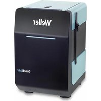
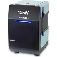
| Product Type | Soldering and Desoldering Station |
| Brand | Weller |
| Model | MG100S |
| Power Supply | 120/230 V ~ 50/60 Hz, 70 W |
| Temperature Range | 100°C - 450°C (200°F - 850°F) approx. |
| Temperature Accuracy | ± 1°C (with Window function) |
| Number of Channels | 2 (WT 2M) |
| Stand-by Function | Adjustable from OFF to 100-300°C (200-600°F), timer 1-99 min |
| Auto-OFF Function | Adjustable from OFF to 1-999 min |
| Lock (LOCK) | 3-digit code, prevents modifications |
| Offset | ± 40°C (± 72°F) |
| Fixed Temperatures | 2 pre-defined activatable temperatures |
| Display | LCD with adjustable backlight (0-100%) |
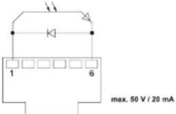
| Potential-free switching output | For Zero Smog or robot (ES FE / ES rob) |
| Potential Compensation | 4 modes: direct grounding, indirect, compensation, potential-free |
| Automatic Tool Detection | Yes, with overload limitation (150 W max) |
| Maintenance and Cleaning | Tin the tip after use, use non-aggressive fluxes, change the tip with the provided tool |
| Safety | Auto-off function, motion detection, potential compensation |
| Spare Parts and Repairability | Tips, compatible soldering tools; customer service: technical-service@weller-tools.com |
| Factory Reset | Press Exit + UP + DOWN for 3 seconds at power-on |
Frequently Asked Questions - MG100S Weller
User questions about MG100S Weller
0 question about this device. Answer the ones you know or ask your own.
Ask a new question about this device
Download the instructions for your Welding machine in PDF format for free! Find your manual MG100S - Weller and take your electronic device back in hand. On this page are published all the documents necessary for the use of your device. MG100S by Weller.
USER MANUAL MG100S Weller
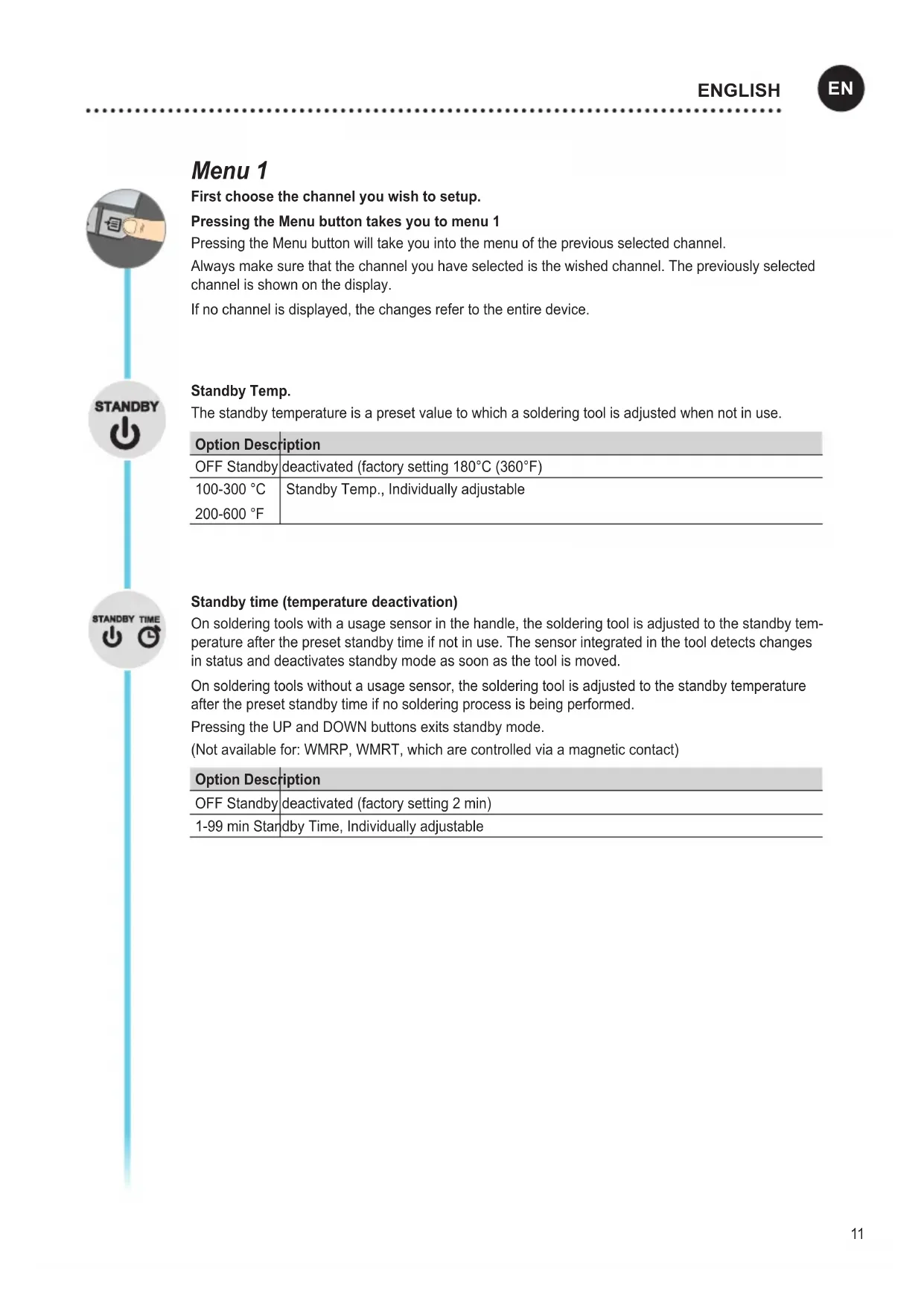
First choose the channel you wish to setup.
Pressing the Menu button takes you to menu 1
Pressing the Menu button will take you into the menu of the previous selected channel.
Always make sure that the channel you have selected is the wished channel. The previously selected channel is shown on the display.
If no channel is displayed, the changes refer to the entire device.
Standby Temp.
The standby temperature is a preset value to which a soldering tool is adjusted when not in use.
| Option Description | |
| OFF Standby | deactivated (factory setting 180°C (360°F) |
| 100-300 °C | Standby Temp., Individually adjustable |
| 200-600 °F | |
Standby time (temperature deactivation)
On soldering tools with a usage sensor in the handle, the soldering tool is adjusted to the standby temperature after the preset standby time if not in use. The sensor integrated in the tool detects changes in status and deactivates standby mode as soon as the tool is moved.
On soldering tools without a usage sensor, the soldering tool is adjusted to the standby temperature after the preset standby time if no soldering process is being performed.
Pressing the UP and DOWN buttons exits standby mode.
(Not available for: WMRP, WMRT, which are controlled via a magnetic contact)
| Option Description | |
| OFF Standby | deactivated (factory setting 2 min) |
| 1-99 min Standby Time, Individually adjustable | |

OFF time
If the soldering tool is not in use, the heating for the soldering tool is deactivated after the OFF time elapses. Temperature deactivation is performed independently of the set standby function. The actual temperature is indicated by flashing LED and serves as a residual heat display. The display reads "OFF".
As long as the soldering tool cools, the residual heat is displayed in the 1-channel display. Cooling also flashes in the display. COOLING
For the 2-channel display, °C / °F flashes in the display of the corresponding channel.
As soon as the temperature falls below 50 °C (122 °F), OFF appears in the display and the backlighting is deactivated.

Pressing the UP and DOWN buttons at the same time exits OFF mode.
| Option 12 | Description |
| OFF OFF time | Deactivated (factory setting 10 min) |
| 1-999 min | OFF time, Individually adjustable |

Window function
Option 1 (factory setting):
Set the potential-free switching output to ES FE.
Limiting the adjustment range to ±1-99 ^ ( ±1-180 ^ ) based on a temperature locked using the „LOCK“ function.
The locked temperature therefore represents the middle of the adjustable temperature window.
Option 2:
Set the potential-free switching output to ES rob; ES FE / rob; ES rob / rob.
Starting from a set, locked temperature, it is possible to set a temperature window of ± 1 - 99^ ( ± 1 - 180^ ) using the WINDOW function. If the actual temperature is within this window, the potential-free contact (optocoupler output) becomes conductive.
| Option 12 | Description |
| OFF Window | function Deactivated (factory setting OFF) |
| 1-99 °C | Window function, Individually adjustable |
| 1-180 °F |

flowchart
graph TD
    A["LOCK"] --> B["OFFSET"]
    B --> C["°C"]
    B --> D["°F"]
LOCK
Lock for the station. After the station is locked, it is no longer possible to change any device settings.
Exception 1: Fixed temperature buttons activated.
Exception 2: Window function Option 1.
All other settings are disabled until the station is unlocked again.
Locking the station
Set the three-digit locking code of your choice (between 001 and 999) and confirm by pressing the Menu button.
The lock is active (the display shows a lock symbol)

Unlocking the station
Press the Menu button. ON appears in the display
Set the three-digit locking code.
Press the Menu button to confirm the code.
Forgotten code?
Please contact our Customer
Service: technical-service@weller-tools.com
Offset
The actual soldering-tip temperature can be adapted by entering a temperature offset around ± 40^ ( ± 72^ ).
°C °F
Changing over the temperature unit.
| Option Description | |
| °C Celsius | |
| °F Fahrenheit | |
Menu 2
First choose the channel you wish to setup.
Pressing and holding the Menu button (three seconds) takes you to menu 2 of the wished channel.
Always make sure that the channel you have selected is the wished channel. The previously selected channel is shown on the display.
If no channel is displayed, the changes refer to the entire device.
Fixed temperatures
Activation of the two fixed temperatures which can be individually adjusted.
| Option 12 | Description |
| ON Fixed temperatures | peratures Activated |
| OFF Fixed temperatures | Deactivated (factory setting) |
If the fixed temperatures are activated, they can be selected and changed by pressing the UP and DOWN buttons.
Backlighting
| Option Description | |
| 0-100% LCD | Brightness (factory setting 80%) |
Floating switching output
Selection of Zero-Smog output or robot output
| Option 1 2 | Description |
| ES FE Zero-S | smog output activated (factory setting) |
| ES rob Robot | output activated |
Sensitivity
| Option Description | |
| 1 | Non-Sensitive – Reacts to heavy (long) movement |
| 2 | ⋮ |
| 3 | Standard (factory setting) |
| 4 | ⋮ |
| 5 | Sensitive - Reacts to light (short) movement |
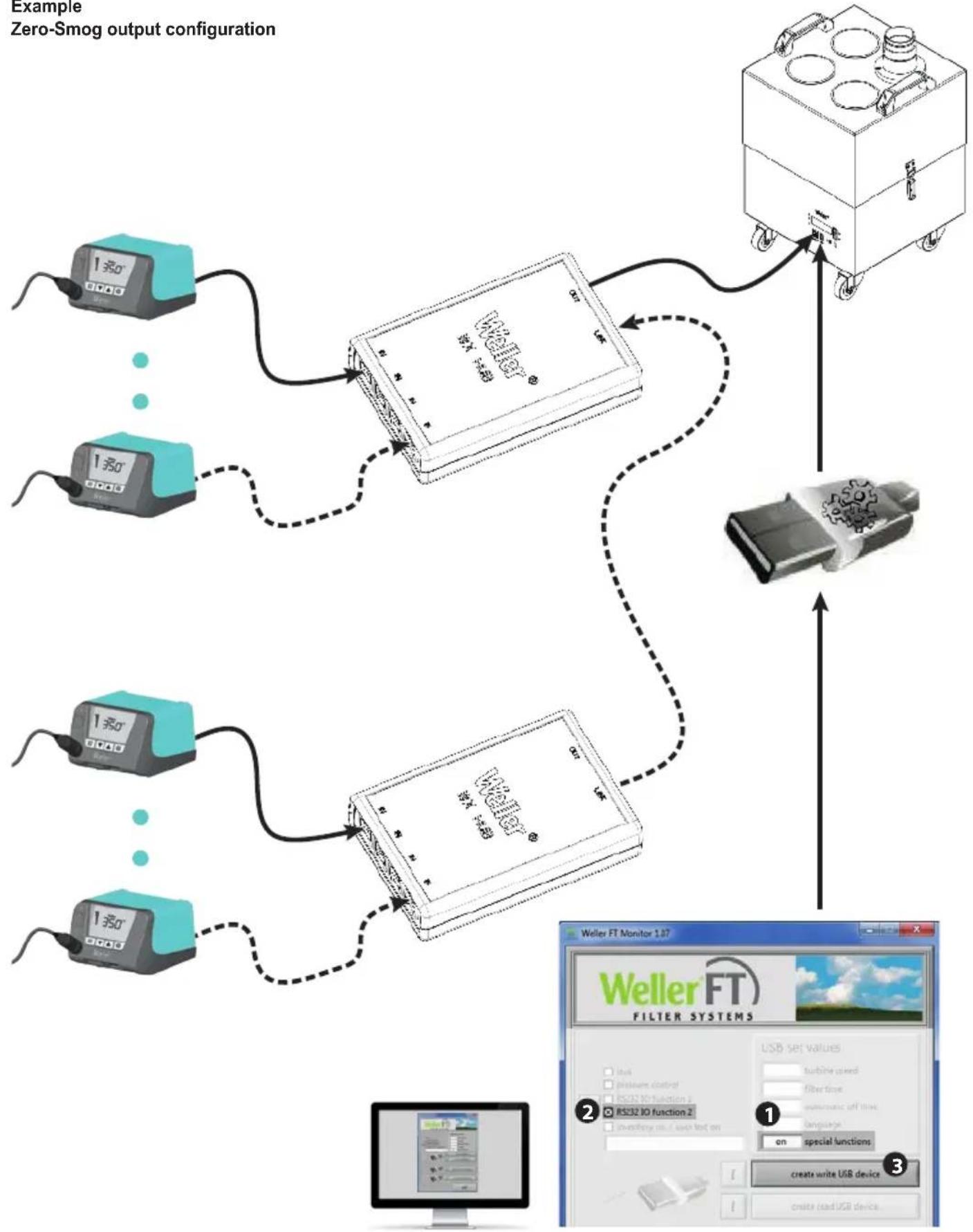
Example
Zero-Smog output configuration
flowchart
graph TD
    A["1串0 0000"] --> B["Weller FT"]
    C["1串0 0000"] --> B
    D["1串0 0000"] --> B
    E["1串0 0000"] --> B
    B --> F["2.5"]
    F --> G["Weller FT Monitor 1.07"]
    G --> H["USB set values"]
    H --> I["RS32 IO function 2"]
    I --> J["on special functions"]
    J --> K["create write USB device"]
    K --> L["create read USB device"]
Resetting to factory settings

When switching on: Press and hold Exit, UP and DOWN for three seconds
Tool recognition and overload limiting
The WT 2M has automatic tool recognition which assigns the relevant control parameters to the connected tool. To prevent overloading a station, only compatible tools are supported:
- Power reduction to 150 W
✗ Tool combination not possible
Equipotential bonding
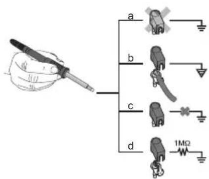
Four variants are possible by connecting the 3.5 mm jack socket differently:
| a Hard-grounded supplied without plug. | |
| b Equipotential bonding with plug, equaliser at centre contact. | |
| c Floating with plug | |
| d Soft-grounded with plug and soldered resistor. Grounded through selected resistor. | |
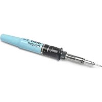
Soldering and desoldering
Carry out soldering work as directed in the operating instructions of your connected soldering tool.
Handling the soldering tips
- Coat the selective and tinnable soldering tip with solder when heating it up for the first time. This removes oxide coatings which have formed during storage and impurities from the soldering tip.
- Make sure that the soldering tip is well coated with solder during breaks between soldering work and prior to storage of the device.
- Do not use aggressive fluxing agents.
• Always make sure that the soldering tips are fitted properly. - Select as low a working temperature as possible.
- Select the largest possible soldering tip shape for the application. Rule of thumb: the soldering tip should be roughly as large as the soldering pad.
- Coat the soldering tip well with solder to ensure that there is efficient heat transfer between the soldering tip and the
soldering area.
- Prior to extended breaks between soldering work, switch off the soldering system or use the Weller function to reduce the temperature when the soldering equipment is not in use.
- Coat the tip with solder prior to storage if you do not intend to use the soldering iron for an extended period of time.
- Apply solder directly to the soldering area, not to the soldering tip.
- Change the soldering tips using the designated tool.
- Do not apply mechanical force to the soldering tip.
Notice
The control units have been adapted to hold a medium-sized soldering tip. Discrepancies may occur if the tip is changed or a different shaped tip is used.
Error messages and error clearance
| Message/symptom Possible cause Remedial measures | ||
| Display: „- - - · Tool has not been detectedTool defectiveTool not compatible | · Check connection of tool to device· Check connected tool | |
| No display function (display OFF) | No mains supply voltage · Turn on mains power switchCheck mains supply voltageCheck device fuse | |
| OFF | Station is on standby or in OFF mode | · Reactive the soldering tool using the UP or DOWN buttons |
| Tool remains cold | Station is on standby or in OFF mode | · Move the gun· Reactive the soldering tool using the UP or DOWN buttons |
| Temperature shown in the displayTool remains cold | Heating defective · Check/replace the soldering tool | |
| Station is not operating as it usually does | Parameters set incorrectly | · Reset the station to the factory settings |
| Settings cannot be changed | Station locked | · Unlocking the station |
| Zero Smog is not running · No mains supply voltageNo signal detected | · Check the mains power supply· Check the interface wiring· Check the interface settings | |
Menú 1
Al conectar: Pulsar durante 3 segundos Exit, UP y DOWN
Verrouiller la station
Ao ligar: Premir Exit, UP e DOWN durante 3 segundos
Station vergrendelen
Station ontgrendelen
Pri zapnutí: Stlačte Exit, UP a DOWN na 3 sekundy
Pri vklopu: 3 sekunde držite Exit, UP in DOWN
flowchart
graph TD
    A["1-second Display"] --> B["Wieler Filter"]
    C["1-second Display"] --> B
    D["1-second Display"] --> B
    E["1-second Display"] --> B
    B --> F["Device with Cart"]
    G["Device with Cart"] --> F
    H["Device with Cart"] --> F
    I["Device with Cart"] --> F
    J["Device with Cart"] --> F
    K["Device with Cart"] --> F
    L["Device with Cart"] --> F
    M["Device with Cart"] --> F
    N["Device with Cart"] --> F
    O["Device with Cart"] --> F
    P["Device with Cart"] --> F
    Q["Device with Cart"] --> F
    R["Device with Cart"] --> F
    S["Device with Cart"] --> F
    T["Device with Cart"] --> F
    U["Device with Cart"] --> F
    V["Device with Cart"] --> F
    W["Device with Cart"] --> F
    X["Device with Cart"] --> F
    Y["Device with Cart"] --> F
    Z["Device with Cart"] --> F
    AA["Device with Cart"] --> F
    AB["Device with Cart"] --> F
    AC["Device with Cart"] --> F
    AD["Device with Cart"] --> F
    AE["Device with Cart"] --> F
    AF["Device with Cart"] --> F
    AG["Device with Cart"] --> F
    AH["Device with Cart"] --> F
    AI["Device with Cart"] --> F
    AJ["Device with Cart"] --> F
    AK["Device with Cart"] --> F
    AL["Device with Cart"] --> F
    AM["Device with Cart"] --> F
    AN["Device with Cart"] --> F
    AO["Device with Cart"] --> F
    AP["Device with Cart"] --> F
    AQ["Device with Cart"] --> F
    AR["Device with Cart"] --> F
    AS["Device with Cart"] --> F
    AT["Device with Cart"] --> F
    AU["Device with Cart"] --> F
    AV["Device with Cart"] --> F
    AW["Device with Cart"] --> F
    AX["Device with Cart"] --> F
    AY["1-second Display"] --> Z
    AZ["1-second Display"] --> Z
    BA["1-second Display"] --> Z
    BB["1-second Display"] --> Z
    BC["1-second Display"] --> Z
    BD["1-second Display"] --> Z
    BE["Wieler FT Monitor 1.07"]
    BF["Weller FT FILTER SYSTEMS"]
    BG["USB set values"]
    BH["Battery speed"]
    BI["Fiber time"]
    BJ["RS32 IO function 1"]
    BK["RS32 IO function 2"]
    BL["Language"]
    BM,on special functions]
    BN["create write USB device"]
    BO["create read USB device"]
Kod uključivanja: Pritisnite Exit, UP i DOWN 3 sekunde
Product Registration
Apex Tool Group, LLC
1000 Lufkin Road
Apex, NC 27539
Tel +1 (866) 498-0484
Fax +1 (919) 387-2639
CHINA
Apex Tool Group
2nd Floor, Area C, 177 Bi Bo Road
Pudong New Area
Shanghai, 201203 P.R.C
Tel: +86 (21) 60880320
www.weller-tools.com