Pyropen Cordless - Welding machine Weller - Free user manual and instructions
Find the device manual for free Pyropen Cordless Weller in PDF.

| Product type | Gas soldering iron with hot air and torch functions |
| Brand | Weller |
| Model | Pyropen Cordless |
| Length (with tip) | 245 mm |
| Weight (with gas) | 105 g |
| Power supply | Non-aromatic butane gas (refillable) |
| Tank capacity | Max. 15 g |
| Hourly consumption | 7 g/h |
| Tip temperature | 200 °C to 500 °C (adjustable in 5 positions) |
| Hot air nozzle temperature | Up to 700 °C |
| Open flame temperature (torch) | Up to 1300 °C |
| Autonomy with tip or nozzle | 1 ½ to 4 hours |
| Autonomy in torch mode | About 50 minutes |
| Main functions | Soldering, hot air, torch (with interchangeable adapters) |
| Maintenance and cleaning | Do not use alcohol-based cleaners; replace defective parts (catalyst, mixing chamber) |
| Safety | Never use near flammable materials; use only in a well-ventilated area; do not store above 50 °C |
| Spare parts and repairability | Tips, nozzles, reflectors, mixing chambers, supports (dedicated Weller references) |
| General information | Manual available in several languages; subject to technical modifications |
Frequently Asked Questions - Pyropen Cordless Weller
User questions about Pyropen Cordless Weller
0 question about this device. Answer the ones you know or ask your own.
Ask a new question about this device
Download the instructions for your Welding machine in PDF format for free! Find your manual Pyropen Cordless - Weller and take your electronic device back in hand. On this page are published all the documents necessary for the use of your device. Pyropen Cordless by Weller.
USER MANUAL Pyropen Cordless Weller
natural_image
Exterior view of a metalworking tool kit with internal components and a labeled pyropen refill (no text or symbols on main objects)Betriebsanleitung - Manuel d'Utilisation - Istruzioni per l'uso - Operating Instruction - Bruksanvisning - Instrucciones para el Manejo - Gebruiksaanwijzing

Order No. Model
Pyropen
- T0051612199 70-01-02
- T0051614299 70-01-52
- T005161599 70-07TU
- T0051616099 RB-TS
- T0051615699 7040U
TÜV NORD
TÜV NORD CERT GmbH
Type Tested
tuev-nord.de
Achtung:
natural_image
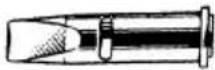
Illustration of hands using a tool to measure a cylindrical object (no text or symbols present)LÖTSPITZEN FÜR WELLER-PYROPEN CORDLESS
natural_image
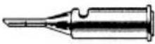
Illustration of hands holding a cylindrical object with a plug inserted (no text or symbols)PANNES POUR FER Á SOUDER WELLER-PYROPEN
natural_image
Line drawing of a hand holding a cylindrical object with a pointed tip, no text or symbols presentVARI TIPI DI PUNTE INTERCAMBIABILI PER VERSATILI APPÖICAZIONI
Punte saldanti
 | Codice Modell DescrizioneT005 16 120 99 70-01-01 Conica ø 1 mmT005 16 124 99 70-01-05 Conica ø 0,5 mm |
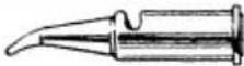 | T005 16 129 99 70-01-10 Curva conica |
 | T005 16 121 99 70-01-02 Cacciavite 3,0 mm (standard)T005 16 132 99 70-01-13 Cacciavite 5,0 mmT005 16 130 99 70-01-11 Cacciavite 7,7 mm |
 | T005 16 122 99 70-01-03 Taglio sbieco ø 2 mmT005 16 123 99 70-01-04 Taglio sbieco ø 3 mmT005 16 125 99 70-01-06 Mirco taglio sbiecoT005 16 127 99 70-01-08 Taglio sbieco 35° ø 2 mm |
 | T005 16 140 99 70-01-50 Ugelli per aria calda ø 1,7 mmT005 16 141 99 70-01-51 Ugelli per aria calda ø 3,3 mmT005 16 142 99 70-01-52 Ugelli per aria calda ø 4,9 mm(standard)T005 16 143 99 70-01-53 Ugelli per aria calda ø 7,0 mm |
 | T005 16 151 99 70-07TU Unità dell'espulsoreT005 16 150 99 70-07SU Unità dell'espulsore |
 | T005 16 158 99 70-01-54Ugello per termorestringenti, raggio 8 mm; 22 mmT005 16 159 99 70-01-55Ugello per termorestringenti, raggio 6 mm; 18 mm |
SMALTIMENTO
IMPORTANT SAFETY INSTRUCTIONS
Please read these Operating Instructions and the attached safety information carefully prior to initial operation of the soldering iron. Failure to observe the safety regulations results in a risk to life and limb. The manufacturer shall not be liable for damage resulting from misuse of the machine or unauthorised alterations.
- Do not use any device which is leaky (gas odour) or is damaged or not in perfect working order.
- Never try to detect leaks with a naked flame. Use only soapy water.
- If damage is found, the device must not be used and the tank must not be refilled.
- Do not fill gas or store near open flame, heater, furnace or combustible materials.
- Use only non-aromatic butane gas as recommended by the manufacturer.
- Be sure to put switch down after use.
- Operate the device only in well-ventilated areas and well away from ignition sources or flammable objects.
- Avoid dropping or causing a hard shock.
- Do not use iron holder designed for the electrical iron. This may cause burning of tool body.
- Do not store under direct sunlight or anywhere that will exceed 50^ C or 122^ F. This will cause fire / explosion as gas pressure become high.
- Do not store near windshield, in trunk of car.
- Keep out of reach of infants.
- Keep hands and combustibles clear out of exhaust opening and tip housing to avoid burns or fire. Keep well away from face and clothing when igniting.
- Do not immerse in water.
- Do not try to disassemble or misuse or alter or tamper.
- Do not drill holes in or open the device.
- Cool down before putting protective cap on.
- Repairs are only to be performed by authorised specialist personnel.
- Refer all repairs to authorised specialist personnel or the manufacturer.
- Before taking soldering tools on board aircraft, always check the applicable transport regulations specified by the airline company.
SPECIFICATIONS
Specifications
Lenght incl. soldering tip 242 mm (soldering and hot blow) 198 mm (torch)
Weight incl. gas filling 105 g (soldering and hot blow) 95 g (torch)
Temperature values About 200°C-500°C Soldering tip end
About 700°C max. at hot blow tip end
About 1.300°C max. at torch (burner)
Burning time per gas filing About 11/2 - 4 hours (soldering and hot blow)
About 50 minutes at max. gas flow (torch)
Te environmental temperature will slightly influence the
burning time
Gas consumption per hour 7g
Filling quantity Max. 15 g
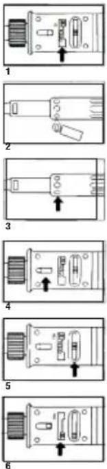
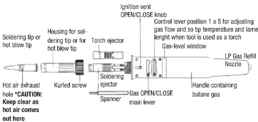
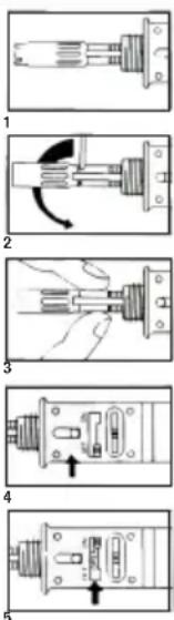
HOW TO USE A SOLDERING TIP AND A HOT BLOW TIP
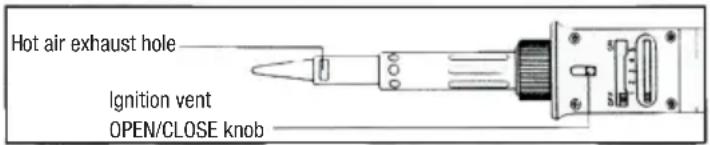
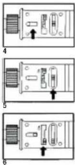
CAUTION: Be sure the ignition vent knob is in backward position. The vent knob and air exhaust hole must be positioned upward when tool is operated.
- Set lever to "ON" position.
- Ignite gas by means of a lighter at ignition vent.
- Wait until inside of ignition vent is red.
- Close the ognition vent holed by pushing knob forward. By closing the holes, the flame turns off and the mixture air/gas in contact with the catalyser produces heat.
- Control tio temperature by control lever.
- To shut off, slide the gas main lever to position "OFF" until it clicks.
For temperature lower than position 1 push main lever to OFF and re-open again after three seconds. This results in lower heat generation of the catalyzer. If temperature is still too high, repeat this procedure.
CAUTION: When using a soldering tip or a hot blow tip, hot air comes out from the exhaust hole in the tip. Be sure to keep clear from the hole to avoid burns.
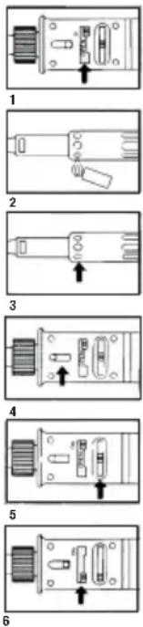
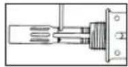
HOW TO USE THE TOOL AS TORCH
- Remove tip and tip housing by untightening knurled screw.
- Push vent knob forward; small round holes on the soldering ejector will appear. Insert the accessory spanner in one of the small holes and untight the soldering ejector. Remove ejector.
- Mount torch ejector in the place of the removed soldering ejector. Use accessory spanner to tighten.
- Set vent knob in backward position.
- Set control lever at 3. Gas OPEN/CLOSE main lever in position "ON".
Never direct the flame nozzle at persons or look into the outlet. Never bring inflammable objects, fluids or gases near the hot soldering iron.
The soldering iron must not be operated without the nozzle.
- Ignite gas by means of a lighter.
- Adjust flame lenght. Do not adjust to maximum lenght as gas will flash and turn off
- Using the ignition vent knob, it is possible to close the round holes at the back of the torch ejector in order to obtain a pre-heat flame.
- To shut off the tool, put the gas main lever on "OFF" until it clicks (red writing not visible any more).
For any job with a soldering tip or with a hot blow tip, the adequate ejector has to be re-installed.
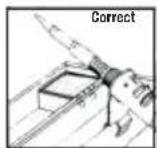
HOW TO USE ACCESSORY IRON HOLDER
Always place the soldering tool in the safety rest while not in use.
Put accessory holder on any box edge as illustrated (on larger nail of holder comes outside of box and two nails inside).
TROUBLE SHOOTING
Trouble Possible reason Correction
No gas flow Empty gas container Refill Clogged mixing chamber Replace
Torch flame has ho power Gas container probably Refill almost empty
Impossible to ignite the gasGas pressure is too high or Adjust correctly Postion 1-5 too low
Tip does not heat up Catalyser is damaged Replace soldering tip Insufficient gas power Refill
Damage at the flame The knurel screw has been Replace ejector orifice overtightened
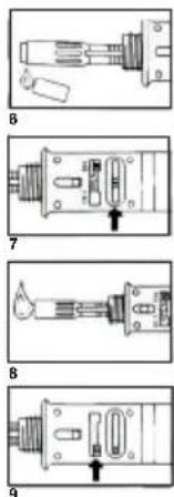
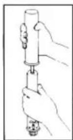
- Use original Weller Pryopen gas (or butan-gas for cigarette lighters)
- Be sure the gas OPEN/CLOSE lever is at "OFF" position.
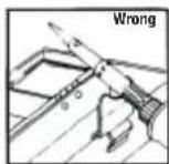
- Hold the Pyropen handle with tip pointing downward, refill nozzle in upright position. Insert nozzle of gas container and press down.
-
As soon as the Pyropen is filled, gas will overflow.
-
Hold the tool firmly and see the windows to read LP gas volume inside.
natural_image
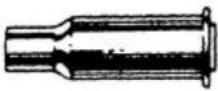
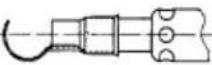
Illustration of a hand holding a cylindrical object with a handle, no text or symbols presentVARIOUS TYPES OF INTERCHANGEABLE TIPS FOR VERSATILE APPLICATION
Please specify the Part Number
Soldering tips
| Part No. Modell DescriptionT005 16 120 99 70-01-01 Tapered needle ø 1 mmT005 16 124 99 70-01-05 Tapered needle ø 0,5 mm | |
| T005 16 129 99 70-01-10 Offset tapered needle | |
| T005 16 121 99 70-01-02 Chisel 3,0 mm (standard)T005 16 132 99 70-01-13 High powered long taper chisel, 5,0 mm widthT005 16 130 99 70-01-11 High powered chisel, 7,7 mm width | |
| T005 16 122 99 70-01-03 Spade ø 2 mmT005 16 123 99 70-01-04 Spade ø 3 mmT005 16 125 99 70-01-06 Mirco spadeT005 16 127 99 70-01-08 Spade ø 2 mm 35° | |
| T005 16 140 99 70-01-50 Hot blow tips ø 1,7 mmT005 16 141 99 70-01-51 Hot blow tips ø 3,3 mmT005 16 142 99 70-01-52 Hot blow tips ø 4,9 mm(standard)T005 16 143 99 70-01-53 Hot blow tips ø 7,0 mm | |
 | T005 16 151 99 70-07TU Torch ejectorT005 16 150 99 70-07SU Solder ejector |
 | T005 16 158 99 70-01-54Shrinking attachment, ø 8 mm; 22 mmT005 16 159 99 70-01-55Shrinking attachment, ø 6 mm; 18 mm |
DISPOSAL
Dispose of replaced equipment parts, filters or old devices in accordance with the rules and regulations applicable in your country.
Subject to technical alterations and amendments!
See the updated operating instructions at www.weller-tools.com.
VIKTIGA SÄKERHETSINSTRUKTIONER
ARBETEN MED OPPEN LÄGA. HÄRDLÖDNING
natural_image
Illustration of a hand using a tool to lift a cylindrical object (no text or symbols present)LÖDSPETSAR FÖR WELLER\_PYROPEN
ATENCIÓN:
natural_image
Illustration of a hand using a tool to lift a cylindrical component (no text or symbols present)PUNTAS PARA SOLDAR PARA EL PROPEN DE WELLER