
GKF 600 Professional - Router BOSCH - Free user manual and instructions
Find the device manual for free GKF 600 Professional BOSCH in PDF.
| Product type | Router |
| Brand | Bosch |
| Model | GKF 600 Professional |
| Rated power input | 600 W |
| No-load speed | 33,000 rpm |
| Tool holder | 6 mm, 8 mm, 1/4" (UK) |
| Weight (according to EPTA 01/2003) | 1.5 kg |
| Protection class | II (double insulation) |
| Sound pressure level | 84 dB(A) |
| Sound power level | 95 dB(A) | Uncertainty K = 3 dB |
| Vibration emission value (EN 60745) | ah = 4.5 m/s² | K = 1.5 m/s² |
| Applications | Edge trimming, grooving, profiling, template routing |
| Machinable materials | Wood, plastics, lightweight construction materials |
| Clamping system | Collet with union nut |
| Depth adjustment | Adjustment wheel and scale |
| Parallel guide | Yes, adjustable |
| Template guide | Yes (accessory) |
| Angle router base | Yes (accessory, tilt 75°) |
| Dust extraction | Dust extraction adapter and cover available (accessories) |
| Switch | On/Off (I/0) |
| Maintenance and cleaning | Regularly clean the ventilation slots and collets |
| Safety | Disconnect before servicing, wear hearing protection, use cable detectors |
| Spare parts | Available through Bosch authorized service (article number required) |
Frequently Asked Questions - GKF 600 Professional BOSCH
User questions about GKF 600 Professional BOSCH
0 question about this device. Answer the ones you know or ask your own.
Ask a new question about this device
Download the instructions for your Router in PDF format for free! Find your manual GKF 600 Professional - BOSCH and take your electronic device back in hand. On this page are published all the documents necessary for the use of your device. GKF 600 Professional by BOSCH.
USER MANUAL GKF 600 Professional BOSCH
GKF 600 Professional

BOSCH
Original instructions
Notice originale
Manual original
Manual original
natural_image
Illustration of a Bosch electric shaver with visible blade and base (no text or symbols)
natural_image
Black and white diagonal striped pattern with no text or symbolsIzvirna navodila
Originalne upute za rad
natural_image
Technical line drawing of a mechanical assembly with no visible text or symbols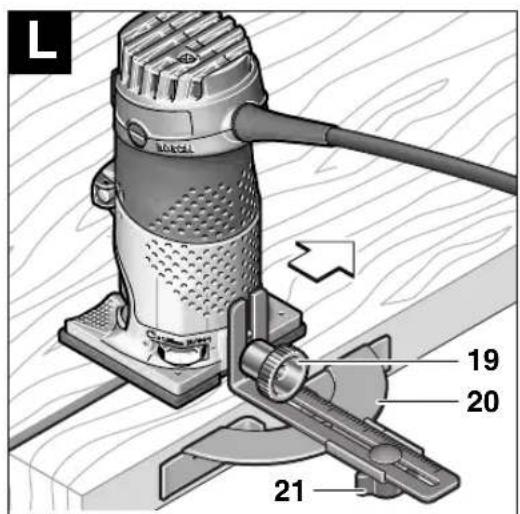
4
2 609 140 541 · 22.1.08

GKF 600
Professional
Technische Daten
Kantenfräse GKF 600
Professional
Sachnummer 3 601 F0A 1..
Senior Vice President Head of Product Engineering Certification

03.12.2007, Robert Bosch GmbH, Power Tools Division
D-70745 Leinfelden-Echterdingen
natural_image
Cross-sectional diagram of a mechanical or hydraulic component with layered structure (no text or symbols)Rated power input [W] 600
No-load speed [rpm] 33 000
Tool holder 6 mm/
8 mm/
1/4" (only UK)
Weight according to
EPTA-Procedure
01/2003 [kg] 1.5
Protection class
回 / II
Please observe the article number on the type plate of your machine. The trade names of the individual machines may vary.
The values given are valid for nominal voltages [U] of 230/240 V. For lower voltages and models for specific countries, these values can vary.
Noise/Vibration Information
Measured values determined according to EN 60 745.
Typically the A-weighted noise levels of the machine are: sound pressure level 84 dB (A); sound power level 95 dB (A).
Uncertainty K = 3 dB.
Wear hearing protection!
Overall vibrational values (vector sum of three directions) determined according to EN 60745: Vibrational emission value a_h=4.5 m/s^2 , uncertainty K=1.5 m/s^2 .
WARNING
The vibration emission level given in this information sheet
has been measured in accordance with a standardised test given in EN 60745 and may be used to compare one tool with another.
The vibration emission level will vary because of the ways in which a power tool can be used and may increase above the level given in this information sheet. This could lead to a significant underestimate of exposure when the tool is used regularly in such a way.
NOTE: To be accurate, an estimation of the level of exposure to vibration experienced during a given period of work should also take into account the times when the tool is switched off and when it is running but not actually doing the job. This may significantly reduce the exposure level over the total working period.
Declaration of Conformity C€
We declare under our sole responsibility that the product described under „Technical data“ is in conformity with the following standards or standardization documents: EN 60745 according to the provisions of the directives 2004/108/EC, 98/37/EC (until 28 Dec 2009), 2006/42/EC (from 29 Dec 2009).
Technical documents at:
Robert Bosch GmbH, PT/ESC,
D-70745 Leinfelden-Echterdingen
Dr. Egbert Schneider Dr. Eckerhard Strötgen
Senior Vice President Head of Product Engineering Certification

03.12.2007, Robert Bosch GmbH, Power Tools Division
D-70745 Leinfelden-Echterdingen
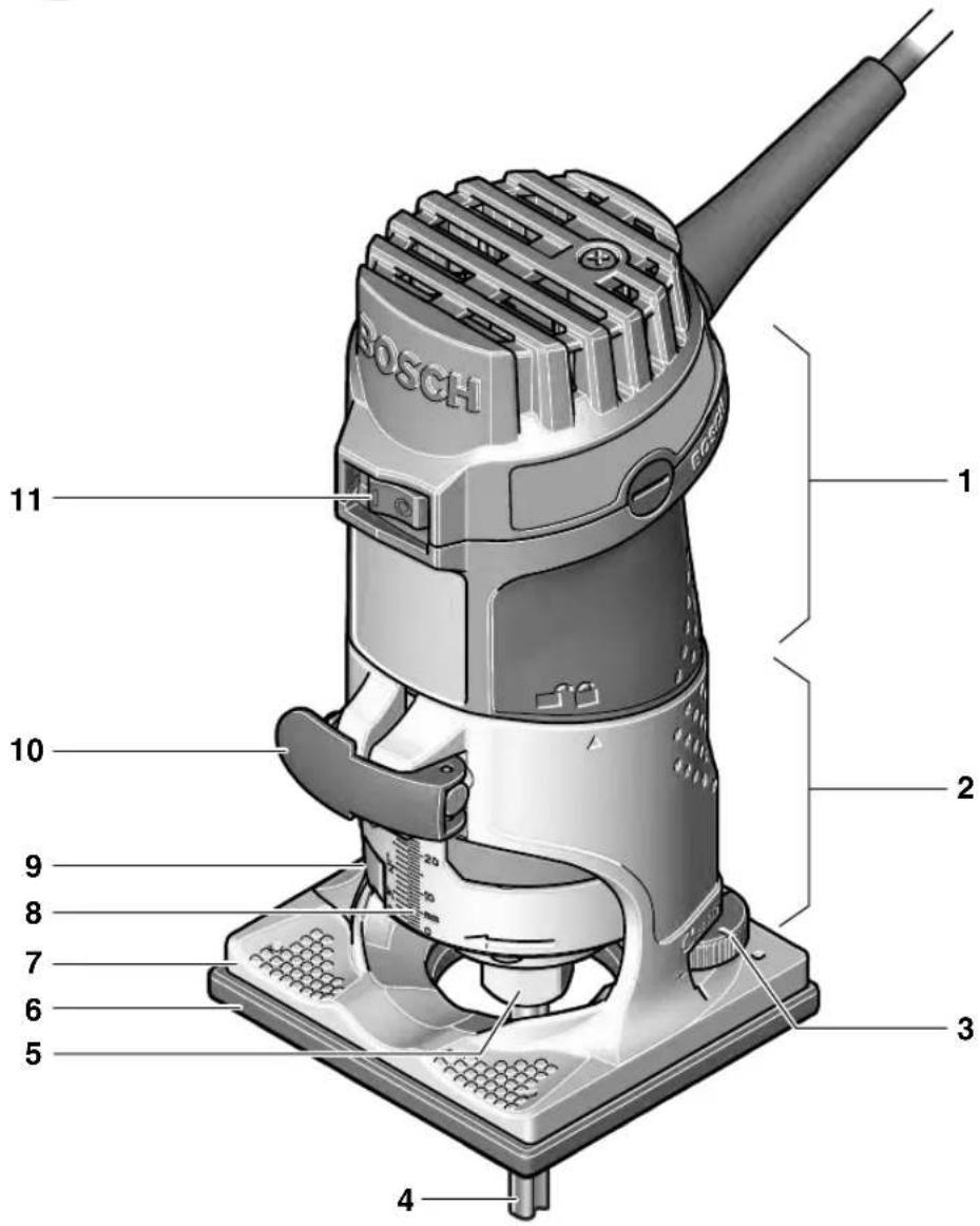
Product Features
While reading the operating instructions, unfold the graphics page for the machine and leave it open.
The numbering of the product features refers to the illustration of the machine on the graphics page.
1 Motor unit
2 Routing base
3 Thumbwheel for depth-of-cut fine adjustment
4 Router bit*
5 Collet chuck
6 Guide plate
7 Base plate
8 Scale for depth-of-cut adjustment
9 Spindle lock button
10 Clamping lever
11 On/Off switch
12 Open-end spanner
13 Collet
14 Guide bushing*
15 Rubber ring
16 Guide plate, round*
17 Fastening screw for base plate (4 x)
18 Centring pin*
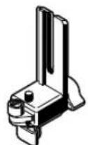
19 Knurled screw for attachment of side stop
20 Parallel guide
21 Wing bolt for parallel guide
22 Roller guide
23 Wing bolt for horizontal alignment of the roller guide
24 Wing bolt for locking of the horizontal alignment
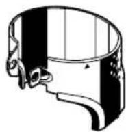
25 Base cover sleeve*
26 Tilt base*
27 Wing bolt for angle adjustment
28 Scale for routing angle adjustment
29 Handle*
30 Extraction hood*
31 Extraction adapter*
32 Side-handle subbase*
* Illustrated or described accessories are not included as standard delivery.

For Your Safety

Read all safety warnings and all instructions. Failure to follow the warnings and instructions may result in electric shock, fire and/or serious injury.
Save all warnings and instructions for future reference.
Additionally, the general safety instructions either in the enclosed booklet or those added in the centre of these operating instructions must be observed.
■ The allowable speed of the tool insert must be at least as high as the maximum speed stated on the machine. Accessories driven in excess of their allowable speed can be destroyed.
■ Routing tools or other tool inserts must fit exactly in the tool holder (collet) of your machine. Tool inserts that do not fit precisely in the tool holder of the machine rotate irregularly, vibrate heavily and can lead to loss of control.
■ Guide the machine against the workpiece only when it is switched on. Otherwise there may be danger of kickback when the tool insert jams in the workpiece.
- Keep your hands away from the routing area and the routing tool. Hold the auxiliary handle or the motor housing with your second hand. When both hands hold the machine, they cannot be injured by the routing tool.
■ Never cut over metal objects, nails or screws. The routing tool can become damaged and lead to increased vibrations.
■ Hold the power tool only by the insulated gripping surfaces when performing an operation where the cutting tool may contact hidden wiring or its own power cord. Contact with a "live" wire will also make exposed metal parts of the power tool "live" and shock the operator.
■ Use suitable detectors to determine if utility lines are hidden in the work area or call the local utility company for assistance. Contact with electric lines can lead to fire and electric shock. Damaging a gas line can lead to explosion. Penetrating a water line causes property damage or may cause an electric shock.
■ Do not use dull or damaged router bits. Dull or damaged router bits cause increased friction, can become jammed and lead to imbalance.
■ Secure the workpiece. A workpiece clamped with clamping devices or in a vice is held more securely than by hand.
■ Do not work materials containing asbestos. Asbestos is considered carcinogenic.
Take protective measures when dust can develop during working that is harmful to one's health, combustible or explosive. Example: Some dusts are regarded as carcinogenic. Wear a dust mask and work with dust/chip extraction when connectable.
■ Always wait until the machine has come to a complete stop before placing it down. The tool insert can jam and lead to loss of control over the power tool.
■ Do not use a machine with a damaged mains cable. Do not touch the damaged cable and pull the mains plug when the cable is damaged while working. Damaged cables increase the risk of an electric shock.
Intended Use
The machine is intended for trimming edges in wood, plastic and light building materials. It is also suitable for routing of grooves, profiles and slots as well as for contour routing.
Mounting
■ Before any work on the machine itself, pull the mains plug.
Disassembling the Motor Unit (see figure A)
For disassembly of the motor unit 1, open the clamping lever 10 and turn the routing base 2 so that the “▲” mark is in line with the “■” symbol on the motor unit. Then pull the motor unit 1 upward to the stop, turn the motor unit 1 in anticlockwise direction to the stop and pull the motor unit 1 out of the routing base 2.
Router Bit Selection
Depending on processing and application, router bits are available in the most different designs and qualities:
Router bits made of high speed steel (HSS) are suitable for the machining of soft materials, e. g., softwood and plastic.
Carbide tipped router bits (HM) are especially suitable for hard and abrasive materials, e. g., hard wood.
Original router bits from the extensive Bosch accessories program are available at your specialist shop.
Inserting Router Bits (see figures B) C
■ Before any work on the machine itself, pull the mains plug.
■ It is recommended to wear protective gloves when inserting or replacing router bits.
Disassemble the motor unit as described in the respective section.
Press the spindle lock button 9 and keep it pressed. Possibly turn the spindle by hand until the lock engages.
■ Press the spindle lock button only when at a standstill.
Loosen the collet chuck 5 with an open-end spanner 12 (size 18 mm) several turns, but do not unscrew the tightening nut.
Insert the shank of the router bit at least 20 mm (shank length) into the collet.
Tighten the collet chuck 5 with the open-end spanner 12 (size 18 mm) and release the spindle lock button 9.

Do not tighten the tightening nut of the collet chuck without a router bit inserted.
Replacing the Collet (see figure D)
Depending on the routing tool to be used, different collets can be inserted, see "Tool Specifications".
The collet 13 must have somewhat play when seated in the tightening nut. The collet chuck 5 (tightening nut with collet) must assemble easily. Should the collet chuck 5 be damaged, replace immediately.
Press the spindle lock button 9 and keep it pressed. Possibly turn the spindle by hand until the lock engages.
Unscrew the collet chuck 5.
Release the spindle lock button 9.
Clean the tool holding fixture and the collet 13 using a soft brush or by blowing out with compressed air.
Tighten the collet chuck 5 again.

Do not tighten the tightening nut of the collet chuck without a router bit inserted.
Mounting the Motor Unit (see figure E)
To mount the motor unit 1, open the clamping lever 10 and bring the two double arrows on the motor unit 1 and the routing base 2 into alignment. Push the drive unit 1 into the routing base 2 and turn the motor unit 1 in clockwise direction until the “▲” mark on the routing base 2 points against the line below the “■” symbol on the motor unit 1. Push the drive unit 1 into the routing base 2.
After mounting is completed, position the "▲" mark of the routing base 2 in line with the "☐" symbol on the motor unit 1 and lock the clamping lever 10.
■ After mounting, always check if the motor unit is seated tightly in the routing base. The pretension of the clamping lever can be changed by readjusting the nut.
Readjusting the Clamping Lever
To readjust the tightening tension, open the clamping lever 10, turn the nut of the clamping lever approx. 45° in clockwise direction using an open-end spanner and then lock the clamping lever 10 again. Check if the motor unit 1 is clamped securely. Do not over tighten the nut.
Starting Operation
Observe correct mains voltage: The voltage of the power source must agree with the voltage specified on the nameplate of the machine. Equipment marked with 230 V can also be connected to 220 V.
Switching On and Off
To start the machine, set the On/Off switch 11 to I.
To switch off the machine, set the On/Off switch 11 to 0.
Setting the Depth-of-cut (see figure F)
■ The adjustment of the depth-of-cut may only be carried out when the trimmer is switched off.
Place the trimmer on the workpiece to be worked.
Open the clamping lever 10, set the “▲” mark on the routing base 2 to the “■” symbol and slowly lower the motor unit until the router touches the workpiece. Fix the motor unit in this position by locking the clamping lever 10.
Read the measuring value off the scale 8 and note it down (zeroing). Add the desired depth-of-cut to this value.
Open the clamping lever 10 and set the motor unit to the calculated scale value. Set the "▲" mark on the routing base 2 to the "☐" symbol and lock the clamping lever 10 again.
Check the carried out depth-of-cut adjustment with a trial cut and correct it, if necessary.
For fine adjustment of the depth-of-cut, set the "▲" mark on the motor unit to the "☐" symbol with the clamping lever 10 open. Adjust the desired depth-of-cut with the thumbwheel 3. Afterwards, lock the clamping lever 10 to securely lock the motor unit in the routing base.
Operating Instructions
Direction of Feed (see figure G
The feed motion of the router must always be carried out against the rotation direction of the router bit (up-grinding).
When routing in the rotation direction of the router bit (down-cutting), the machine can break loose, eliminating control by the user.
Routing Process
■ Use the machine only with the routing base mounted. Loss of control over the machine can cause injuries.
■ Before beginning the routing procedure, check if the “▲” mark on the routing base 2 is positioned in line with the “■” symbol on the motor unit 1.
Note: Take into consideration that the router bit 4 always extends out of the base plate 7. Do not damage the template or the workpiece.
Adjust the depth-of-cut as described previously. Switch the machine on and guide it to the location subject to working.
Carry out the routing procedure applying uniform feed.
Switch the machine off after finishing the routing process. Do not place the power tool down until after the router bit has come to a complete stop.
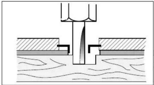
Routing with Guide Bushing
The guide bushing 14 enables template and pattern routing on workpieces.
Inserting guide bushing 14 (see figure H)
Unscrew the four fastening screws on the bottom side of the guide plate 6 and remove the guide plate 6. Insert the rubber ring 15 and then the guide bushing 14 into the round guide plate 16 as shown in the figure. Screw the round guide plate 16 to the base plate 7 with the countersunk screws provided.
Adjusting/centring the guide bushing (see figure 1)
To ensure that the distance from router bit centre and guide bushing edge is uniform, the guide bushing and the guide plate can be adjusted to each other, if required.
Loosen the fastening screws 17 by approx. 2 turns so that the round guide plate 16 can be moved freely.
Insert the centring pin 18 into the tool holder as shown in the figure. Hand-tighten the tightening nut so that the centring pin can still be moved.
Align the centring pin 18 and the guide bushing 14 by lightly moving the round guide plate 16.
Tighten the fastening screws 17 again and remove the centring pin 18 from the tool holder.
Routing Process

Select a router bit with a smaller diameter than the inside diameter of the guide bushing.
Place the machine with the guide bushing 14 against the template.
Guide the machine with projecting guide bushing along the template, applying light sideward pressure.
Note: The template must have a minimum thickness of 8 mm, due to the projecting height of the guide bushing.
natural_image
Cross-sectional diagram of a mechanical or hydraulic component with layered structure (no text or symbols)Shaping or Molding Applications (see figure K)
For shaping or molding applications without the use of a parallel guide, the router must be equipped with a pilot or a ball bearing.
Guide the machine from the side to the workpiece until the pilot or the ball bearing of the trimmer faces against the workpiece edge to be worked. Guide the machine alongside the edge of the workpiece, ensuring rectangular support. Excessive pressure can damage the edge of the workpiece.
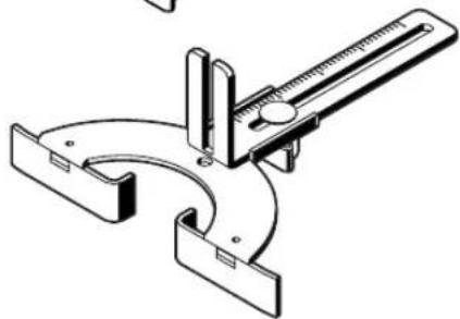
Routing with Parallel Guide (see figure L)
Fasten the parallel guide 20 to the routing base with the knurled screw 19.
Adjust the desired depth setting on the parallel guide with wing bolt 21.
Guide the machine with uniform feed and sideward pressure against the parallel guide 20 alongside the workpiece edge.
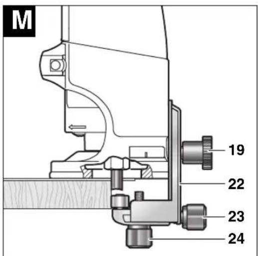
Routing with the Roller Guide (see figure M)
The roller guide 22 is used for routing edges with router bits without pilot or ball bearing.
Fasten the roller guide 22 to the routing base with the knurled screw 19.
Guide the machine with uniform feed alongside the workpiece edge.
Lateral Clearance
In order to change the amount of material removal, the lateral clearance between workpiece and the guide roller of the roller guide can be adjusted.
Loosen wing bolt 24, adjust the desired lateral clearance by turning wing bolt 23 and tighten wing bolt 24 again.
Height
Adjust the vertical alignment of the roller guide depending on the router bit in use and the thickness of the material to be worked.
Loosen the knurled screw 19 on the roller guide, slide the roller guide to the desired position and tighten the knurled screw again.
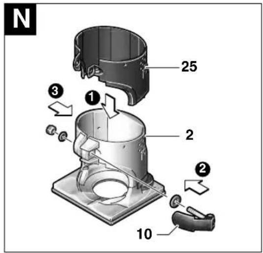
Assembling the Base Cover Sleeve (see figure N)
For assembly of the base cover sleeve 25, remove the clamping lever 10. Place the base cover sleeve 25 onto the routing base 2 from above and reassemble the clamping lever 10 again in such a manner that the motor unit 1 is held securely in the routing base when the clamping lever is locked.
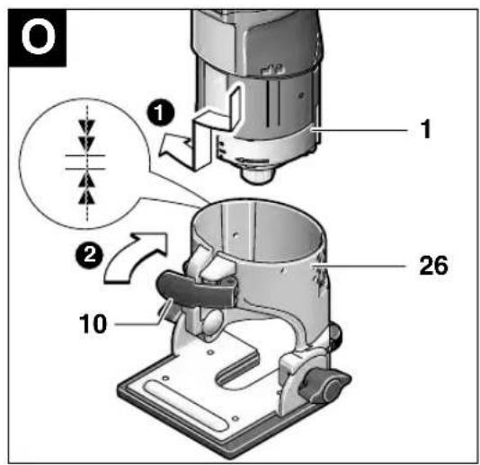
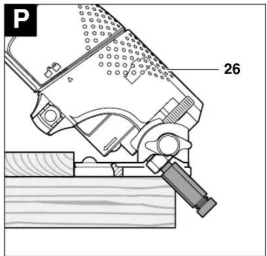
Routing with Tilt Base (see figures ☐) ☐
The tilt base 26 is particularly suitable for flush routing of laminated edges at hard to reach locations, for routing special angles as well as for bevelling edges.
When bevelling edges using the tilt base 26, the router bit must be equipped with a pilot or a ball bearing.
The tilt base is mounted according to the instructions for the routing base 2.
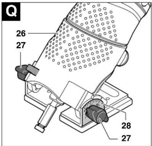
To achieve precise angles, the tilt base 26 is equipped with adjustment notches in steps of 7.5°. The complete adjustment range is 75°; the tilt base inclines to 45° toward the front and 30°
toward the rear. Loosen both wing bolts 27 to adjust the angle. Adjust the desired angle using the scale 28 and tighten wing bolts 27 again.
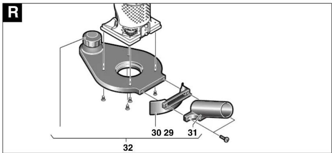
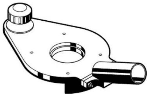
Routing with the Side-handle Subbase (see figure R)
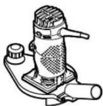
The side-handle subbase 32 can be mounted in place of guide plate 6. It offers an additional handle 29 as well as a connection possibility for dust extraction.
Unscrew the four fastening screws on the bottom side of the guide plate 6 and remove the guide plate. Screw the side-handle subbase 32 to the base plate as shown in the figure using the countersunk screws provided.
To connect dust extraction, screw the extraction adapter 31 to the side-handle subbase 32 with the two screws. Connect an extraction hose with a diameter of 19/35 mm to the extraction adapter 31.
To ensure optimum dust extraction, the extraction adapter 31 should be cleaned regularly.
For working edges, additionally use the extraction hood 30. Mount the extraction hood as shown in the figure.
For working smooth face surfaces, remove the extraction hood 30.
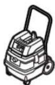
The machine can be plugged directly into the receptacle of a Bosch all-purpose vacuum cleaner with remote starting control. The vacuum cleaner starts automatically when the machine is switched on.
The vacuum cleaner must be suitable for the material to be worked.
When vacuuming dry dust that is especially detrimental to health or carcinogenic, use a special vacuum cleaner.
Maintenance and Cleaning
■ Before any work on the machine itself, pull the mains plug.
■ For safe and proper working, always keep the machine and its ventilation slots clean.
If the machine should fail despite the care taken in manufacturing and testing procedures, repair should be carried out by an authorized after-sales service agent for Bosch power tools.
In all correspondence and spare parts orders, please always include the 10-digit article number given on the nameplate of the machine.
WARNING! Important instructions for connecting a new 3-pin plug to the 2-wire cable. The wires in the cable are coloured according to the following code:
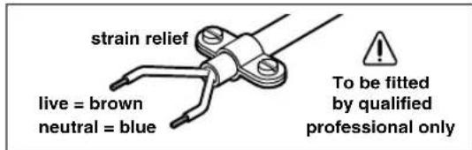
Do not connect the blue or brown wire to the earth terminal of the plug.
Important: If for any reason the moulded plug is removed from the cable of this machine, it must be disposed of safely.
Disposal
Power tools, accessories and packaging should be sorted for environmental-friendly recycling.
Only for EC countries:
Do not dispose of power tools into household waste!
According to the European Directive 2002/96/EC on waste electrical and electronic equipment and its incorporation into national law,
power tools that are no longer suitable for use must be separately collected and sent for recovery in an environmental-friendly manner.
After-Sales Service and Customer Assistance
Our after-sales service responds to your questions concerning maintenance and repair of your product as well as spare parts. Exploded views and information on spare parts can also be found under:
www.bosch-pt.com
Our customer consultants answer your questions concerning best buy, application and adjustment of products and accessories.
Great Britain
Robert Bosch Ltd. (B.S.C.)
P.O. Box 98
Broadwater Park
North Orbital Road
Denham
Uxbridge
UB 9 5HJ
Tel. Service: +44 (0844) 736 0109
Fax: +44 (0844) 736 0146
Australia, New Zealand and Pacific Islands
Robert Bosch Australia Pty.Ltd.
Power Tools
Locked Bag 66
Clayton South VIC 3169
Customer Contact Center
Inside Australia:
Phone: +61 (01300) 307 044
Fax: + 61 (01300) 307 045
Inside New Zealand:
Phone: +64 (0800) 543 353
Fax: +64 (0800) 428 570
Outside AU and NZ:
Phone: +61 (03) 9541 5555
www.bosch.com.au
Subject to change without notice
Senior Vice President Head of Product
Engineering Certification

03.12.2007, Robert Bosch GmbH, Power Tools Division D-70745 Leinfelden-Echterdingen
Senior Vice President Head of Product
Engineering Certification
Mr. Macau, v. Ma
03.12.2007, Robert Bosch GmbH, Power Tools Division
D-70745 Leinfelden-Echterdingen
natural_image
Cross-sectional diagram of a mechanical or hydraulic component with layered structure (no text or symbols)Fresado de cantos lisos o perfilados (ver figura K
Robert Bosch Argentina Industrial S.A.
Av. Cordoba 5160
C1414BAW Ciudad Autonoma de Buenos Aires
Atencion al Cliente
Tel.: +54 (0810) 555 2020
E-Mail: herramientas.bosch@ar.bosch.com
Perú
Autorex Peruana S.A.
Senior Vice President Head of Product Engineering Certification

03.12.2007, Robert Bosch GmbH, Power Tools Division D-70745 Leinfelden-Echterdingen
natural_image
Cross-sectional diagram of a mechanical or hydraulic component with layered structure (no text or symbols)Senior Vice President Head of Product
Engineering Certification
Mr. A##n, v. M#j
03.12.2007, Robert Bosch GmbH, Power Tools Division D-70745 Leinfelden-Echterdingen
Componenti illustrati
natural_image
Cross-sectional diagram of a mechanical or hydraulic component with layered structure (no text or symbols)Senior Vice President Head of Product Engineering Certification

03.12.2007, Robert Bosch GmbH, Power Tools Division
D-70745 Leinfelden-Echterdingen
natural_image
Cross-sectional diagram of a mechanical or hydraulic component with layered structure (no text or symbols)Senior Vice President Head of Product Engineering Certification

03.12.2007, Robert Bosch GmbH, Power Tools Division D-70745 Leinfelden-Echterdingen
Illustrerede komponenter
natural_image
Cross-sectional diagram of a mechanical or hydraulic component with layered structure (no text or symbols)Bosch Service Center
For el-værktøj
Telegrafvej 3
2750 Ballerup
Tel. Service Center: +45 (04489) 8855
Fax: +45 (04489) 87 55
E-Mail: vaerktoej@dk.bosch.com
Senior Vice President Head of Product
Engineering Certification

03.12.2007, Robert Bosch GmbH, Power Tools Division
D-70745 Leinfelden-Echterdingen
Illustrerade komponenter
natural_image
Cross-sectional diagram of a mechanical or hydraulic component with layered structure (no text or symbols)Dr. Egbert Schneider Dr. Eckerhard Strötgen Senior Vice President Head of Product Engineering Certification
pp. Macau, v. Macau
03.12.2007, Robert Bosch GmbH, Power Tools Division D-70745 Leinfelden-Echterdingen
Illustrerte komponenter
natural_image
Cross-sectional diagram of a mechanical or hydraulic structure with layered components and no visible text or symbolsSenior Vice President Head of Product
Engineering Certification

03.12.2007, Robert Bosch GmbH, Power Tools Division D-70745 Leinfelden-Echterdingen
Kuvassa olevat osat
natural_image
Cross-sectional diagram of a mechanical or hydraulic component with layered structure (no text or symbols)Dr. Egbert Schneider Dr. Eckerhard Strötgen Senior Vice President Head of Product Engineering Certification

03.12.2007, Robert Bosch GmbH, Power Tools Division D-70745 Leinfelden-Echterdingen
natural_image
Cross-sectional diagram of a mechanical or hydraulic structure with layered components and no visible text or symbolsDr. Egbert Schneider Dr. Eckerhard Strötgen Senior Vice President Head of Product Engineering Certification

03.12.2007, Robert Bosch GmbH, Power Tools Division D-70745 Leinfelden-Echterdingen
natural_image
Cross-sectional diagram of a mechanical or hydraulic system with layered components and no visible text or symbolsBosch San. ve Tic. A.S.
Ahi Evran Cad. No:1 Kat:22
Polaris Plaza
80670 Maslak/Istanbul
Dr. Egbert Schneider Dr. Eckerhard Strötgen Senior Vice President Head of Product Engineering Certification

03.12.2007, Robert Bosch GmbH, Power Tools Division D-70745 Leinfelden-Echterdingen
natural_image
Cross-sectional diagram of a mechanical or hydraulic component with layered structure (no text or symbols)Robert Bosch Sp.z o.o.
Senior Vice President Head of Product Engineering Certification
Mr. Macau, v. Macau
03.12.2007, Robert Bosch GmbH, Power Tools Division D-70745 Leinfelden-Echterdingen
Zobrazené komponenty
natural_image
Cross-sectional diagram of a mechanical or hydraulic structure with layered components and no visible text or symbolsServis Service Center PT
K Vápence 1621/16
692 01 Mikulov
Tel. +420 (519) 305 700
Fax: +420 (519) 305 705
E-Mail: servis.naradi@cz.bosch.com
www.bosch.cz
Změny vyhrazeny
Technické údaje
Fréza na hrany GKF 600
Professional
Dr. Egbert Schneider Dr. Eckerhard Strötgen Senior Vice President Head of Product Engineering Certification
Mr. Macau, v. Mioje
03.12.2007, Robert Bosch GmbH, Power Tools Division D-70745 Leinfelden-Echterdingen
Vyobrazené komponenty
natural_image
Cross-sectional diagram of a mechanical or hydraulic component with layered structure (no text or symbols)Dr. Egbert SchneiderDr. Eckerhard Strötgen Senior Vice President Head of Product EngineeringCertification
ma. Jmua, v. Mioje
03.12.2007, Robert Bosch GmbH, Power Tools Division D-70745 Leinfelden-Echterdingen
natural_image
Cross-sectional diagram of a mechanical or hydraulic component with layered structure (no text or symbols)Dr. Egbert Schneider Dr. Eckerhard Strötgen Senior Vice President Head of Product Engineering Certification

03.12.2007, Robert Bosch GmbH, Power Tools Division D-70745 Leinfelden-Echterdingen
natural_image
Cross-sectional diagram of a mechanical or hydraulic structure with layered components and water flow (no text or symbols)Dr. Egbert Schneider Dr. Eckerhard Strötgen Senior Vice President Head of Product Engineering Certification

03.12.2007, Robert Bosch GmbH, Power Tools Division D-70745 Leinfelden-Echterdingen
Elemente componente
natural_image
Cross-sectional diagram of a mechanical or hydraulic component with no visible text or symbolsBosch Service Center
Str. Horia Măcelariu Nr. 30-34,
013937-Bucureşti
Tel. Service scule electrice:
+40 (021) 4 05 75 40
Fax.: +40 (021) 4 05 75 66
E-Mail: infoBSC@ro.bosch.com
Dr. Egbert Schneider Dr. Eckerhard Strötgen Senior Vice President Head of Product Engineering Certification
Mr. Amara, v. M. S. J. C.
03.12.2007, Robert Bosch GmbH, Power Tools Division D-70745 Leinfelden-Echterdingen
Изобразени елементи
natural_image
Cross-sectional diagram of a mechanical or hydraulic component embedded in water, showing structural layers and no text or symbols.Senior Vice President Head of Product Engineering Certification
03.12.2007, Robert Bosch GmbH, Power Tools Division D-70745 Leinfelden-Echterdingen
Komponente sa slike
Molimo otvorite preklopljenu stranicu sa prikazom mašine i pratite prikaz na ovoj stranici dok čitate uputstvo za rad.
natural_image
Cross-sectional diagram of a mechanical or hydraulic system with layered components and no visible text or symbolsObrada ivica ili glodanje fazona (pogl. sliku K
Kod obrade ivica ili fazonskog glodanja bez paralelnog graničnika mora alat za glodanje da bude opremljen sa rukavcem vodjice ili kugličnim ležajem.
Navodite električni alat sa strane na radni komad, sve dok rukavac vodjice ili kuglični ležaj glodala ne nalegne na ivicu radnog komada koji se obradjuje. Vodite električni alat duž ivice radnog komada i pritom pazite na naleganje koje odgovara uglu. Suviše jak pritisak može oštetiti ivicu radnog komada.
Glodanje sa paralelnim graničnikom (pogl. sliku L)
Prčvrstite paralelni graničnik 20 na korpi za glodanje sa nareckanim zavrtnjem 19.
Podesite sa leptir zavrtnjem na paralelnom graničniku 21 željenu dubinu graničnika.
Vodite električni alat sa ravnomernim guranjem napred na ivici radnog komada i bočnim pritiskom na paralelnom graničniku 20.
Dr. Egbert Schneider Dr. Eckerhard Strötgen Senior Vice President Head of Product Engineering Certification

03.12.2007, Robert Bosch GmbH, Power Tools Division D-70745 Leinfelden-Echterdingen
Komponente prikazane na sliki
natural_image
Cross-sectional diagram of a mechanical or hydraulic structure with layered components and no visible text or symbolsRezkanje robov ali profilov (glejte sliko K
Dr. Egbert Schneider Dr. Eckerhard Strötgen Senior Vice President Head of Product Engineering Certification
Mr. Macau, v. Mioje
03.12.2007, Robert Bosch GmbH, Power Tools Division D-70745 Leinfelden-Echterdingen
Prikazani dijelovi
natural_image
Cross-sectional diagram of a mechanical or hydraulic system with layered components and no visible text or symbolsObrada rubova ili profilno kopiranje (vidjeti sl. K
Senior Vice President Head of Product Engineering Certification
Mr. Aman, v. M. S.
03.12.2007, Robert Bosch GmbH, Power Tools Division D-70745 Leinfelden-Echterdingen
Seadme osad
natural_image
Cross-sectional diagram of a mechanical or hydraulic system with layered components and no visible text or symbolsDr. Egbert Schneider Dr. Eckerhard Strötgen Senior Vice President Head of Product Engineering Certification

03.12.2007, Robert Bosch GmbH, Power Tools Division D-70745 Leinfelden-Echterdingen
natural_image
Cross-sectional diagram of a mechanical or hydraulic structure with layered components and no visible text or symbolsDr. Egbert Schneider Dr. Eckerhard Strötgen Senior Vice President Head of Product Engineering Certification

03.12.2007, Robert Bosch GmbH, Power Tools Division D-70745 Leinfelden-Echterdingen
natural_image
Cross-sectional diagram of a mechanical or hydraulic component with layered structure (no text or symbols)natural_image
Technical line drawing of a mechanical clamp or bracket device (no text or symbols)2 608 000 334
2 609 100 386
2 608 000 332
natural_image
Technical line drawing of a mechanical clamp or clamp device (no text or symbols)2 608 000 331
natural_image
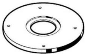
Technical drawing of a circular mechanical flange with bolt holes (no text or symbols)2 608 000 333
natural_image
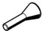
Technical line drawing of a mechanical component with flange and cylindrical shaft (no text or symbols)2 608 000 335

6 mm 2 608 570 133
8 mm 2 608 570 134
1/4" 2 608 570 135

10,8 mm 2 609 200 282
13 mm 2 609 200 138
13,8 mm 2 609 200 283
17 mm 2 609 200 139
24 mm 2 609 200 140
27 mm 2 609 200 141
30 mm 2 609 200 142
40 mm 2 609 200 312
8 mm 2 609 200 310
1/4" 2 609 200 317
natural_image
Line drawing of a mechanical device with no visible text or symbols
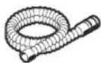


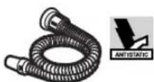
∅ 19 mm
3 m 2 600 793 009
1 609 200 933
GAS 25/50/50 M
5 m 1 610 793 002

natural_image
Line drawing of a mechanical device with no visible text or symbols
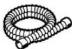

∅ 35 mm
3 m 2 609 390 392
5 m 2 609 390 393
GAS 25/50/50 M
natural_image
Line drawing of a mechanical device with no visible text or symbols

∅ 19 mm
3 m 2 607 002 161
5 m 2 607 002 162
GAS 25/50/50 M
∅ 35 mm
3 m 2 607 002 163
5 m 2 607 002 164
natural_image
Black and white diagonal striped pattern with no text or symbols
BOSCH
Robert Bosch GmbH
Power Tools Division
70745 Leinfelden-Echterdingen
www.bosch-pt.com
2 609 140 541 (2008.01) O / 196


- GKF 600 Professional
- BOSCH
- Technische Daten
- Kantenfräse GKF 600
- Professional
- Noise/Vibration Information
- Wear hearing protection!
- WARNING
- Declaration of Conformity C€
- Product Features
- For Your Safety
- Save all warnings and instructions for future reference.
- Intended Use
- Mounting
- Disassembling the Motor Unit (see figure A)
- Router Bit Selection
- Inserting Router Bits (see figures B) C
- Replacing the Collet (see figure D)
- Mounting the Motor Unit (see figure E)
- Readjusting the Clamping Lever
- Starting Operation
- Switching On and Off
- Setting the Depth-of-cut (see figure F)
- Operating Instructions
- Direction of Feed (see figure G
- Routing Process
- Routing with Guide Bushing
- Inserting guide bushing 14 (see figure H)
- Adjusting/centring the guide bushing (see figure 1)
- Select a router bit with a smaller diameter than the inside diameter of the guide bushing.
- Shaping or Molding Applications (see figure K)
- Routing with Parallel Guide (see figure L)
- Routing with the Roller Guide (see figure M)
- Lateral Clearance
- Height
- Assembling the Base Cover Sleeve (see figure N)
- Routing with Tilt Base (see figures ☐) ☐
- Routing with the Side-handle Subbase (see figure R)
- Maintenance and Cleaning
- Disposal
- Only for EC countries:
- After-Sales Service and Customer Assistance
- www.bosch-pt.com
- Great Britain
- Australia, New Zealand and Pacific Islands
- Fresado de cantos lisos o perfilados (ver figura K
- Perú
- Componenti illustrati
- Illustrerede komponenter
- Illustrerade komponenter
- Illustrerte komponenter
- Kuvassa olevat osat
- Zobrazené komponenty
- Technické údaje
- Fréza na hrany GKF 600
- Vyobrazené komponenty
- Elemente componente
- Изобразени елементи
- Komponente sa slike
- Obrada ivica ili glodanje fazona (pogl. sliku K
- Glodanje sa paralelnim graničnikom (pogl. sliku L)
- Komponente prikazane na sliki
- Rezkanje robov ali profilov (glejte sliko K
- Prikazani dijelovi
- Obrada rubova ili profilno kopiranje (vidjeti sl. K
- Seadme osad
Brand : BOSCH
Model : GKF 600 Professional
Category : Router