POF 1100 AE - Router BOSCH - Free user manual and instructions
Find the device manual for free POF 1100 AE BOSCH in PDF.
| Product Type | Router |
| Brand | Bosch |
| Model | POF 1100 AE |
| Rated input power | 1100 W |
| Output power | 550 W |
| No-load speed | 11,000 – 28,000 rpm |
| Constant electronics | No |
| Speed preselection | Yes, by wheel (6 positions) |
| Tool holder | Collet chuck 6/8 mm and 1/4" |
| Plunge stroke | 55 mm |
| Weight without cable | 3.0 kg |
| Protection class | II (double insulation) |
| Supply voltage | 230/240 V (compatible 220 V) |
| Spindle lock | Yes |
| Start lock | Yes (safety) |
| Depth stop | Yes, coarse and fine adjustment (3 levels) |
| Copying ring | Yes (accessory) |
| Parallel guide | Yes (accessory) |
| Dust extraction adapter | Yes (diameter 35 mm) |
| Sound pressure level | 95 dB(A) |
| Sound power level | 106 dB(A) |
| Vibration (forearm) | < 2.5 m/s² |
Frequently Asked Questions - POF 1100 AE BOSCH
User questions about POF 1100 AE BOSCH
0 question about this device. Answer the ones you know or ask your own.
Ask a new question about this device
Download the instructions for your Router in PDF format for free! Find your manual POF 1100 AE - BOSCH and take your electronic device back in hand. On this page are published all the documents necessary for the use of your device. POF 1100 AE by BOSCH.
USER MANUAL POF 1100 AE BOSCH
Operating instructions
natural_image
Technical illustration of a Bosch electric drill press mechanism (no text or symbols visible)
Deutsch
English
Français
Español
Português
Italiano
Nederlands
Dansk
Svenska
Norsk
Suomi
Ελληνικά
Türkçe


text_image
1 2 3 4 5 6 7 8 9 10 11 12 13 20 19 18 17 16 15 14 POF 1100 AE
text_image
POF 1100 AE 21POF 1300 ACE
text_image
22 24 23 16 16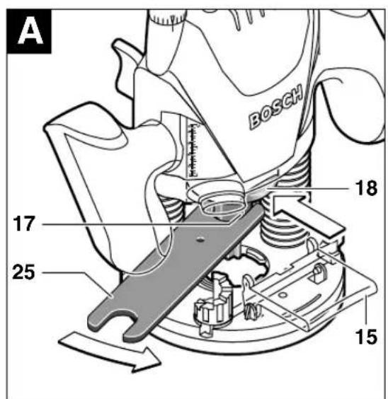
text_image
A BOSCH 17 25 18 153·1609 929 F23·04.04
text_image
B 12 26 27 28


text_image
C 24 1 + - 3 0 2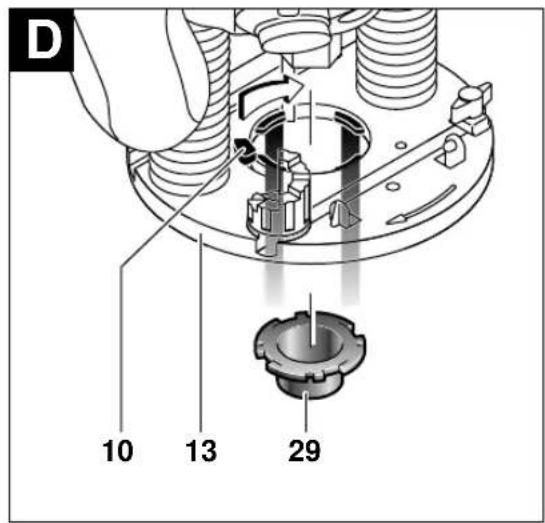
text_image
D 10 13 29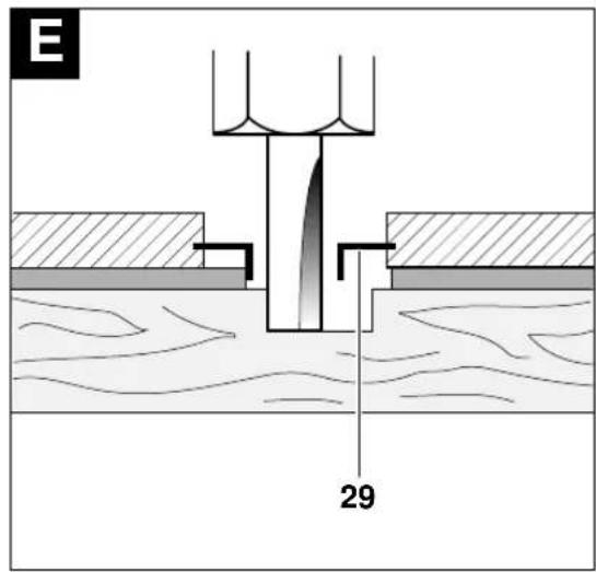
text_image
E 29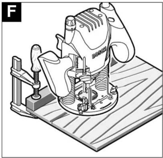
natural_image
Technical illustration of a Bosch hover machine on a wooden workbench, no text or symbols present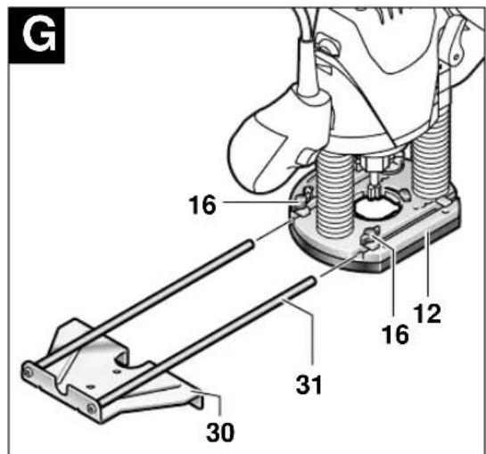
text_image
G 16 12 16 31 30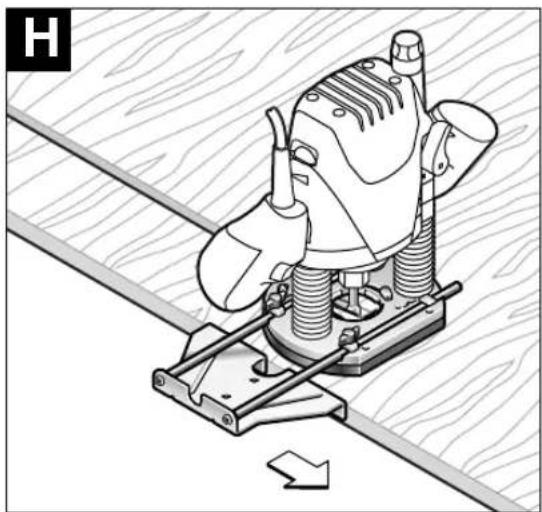
natural_image
Mechanical assembly diagram showing a cam or clamp mechanism with no visible text or symbols4·1609 929 F23·04.04

text_image
1 33 12 30 32
natural_image
Illustration of a mechanical tool with a drill bit and a 3D coordinate axis indicator (no text or symbols)
text_image
L 12 30 34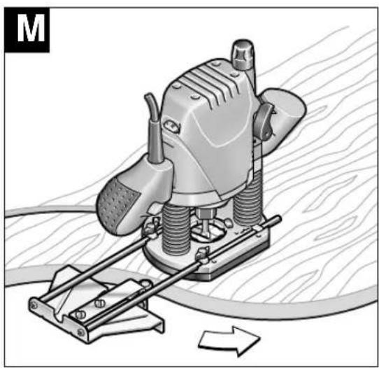
natural_image
Mechanical device with threaded base and lever mechanism, no visible text or symbols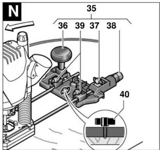
text_image
N 35 36 39 37 38 40
text_image
35 31 41 425·1609 929 F23·04.04
Gerätekennwerte
Oberfräse POF 1100 AE POF 1300 ACE
Bestellnummer 0 603 26A 0.. 0 603 26C 7..
natural_image
Simple diagram showing a wave interacting with a surface, no text or symbols presentnatural_image
Diagram showing a mechanical or fluid system with an arrow indicating direction, no text or symbols presentSenior Vice President Head of Product
Engineering Certification
ppa. A##u i.v. Pu#yen
| Order number 0 603 26A 0.. 0 603 26C 7.. | |||
| Rated input power* [W] 1 100 1 300 | |||
| Output power [W] 550 650 | |||
| No-load speed | [rpm] | 11 000–28 000 | 11 000–28 000 |
| Constant electronic control | - | ● | |
| Speed preselection | ● | ● | |
| Dust extraction | ● | ● | |
| Tool holder | [mm] 6/8 | 6/8 | |
| 1/4" | 1/4" | ||
| Plunge depth | [mm] 55 | 55 | |
| Weight without cable, approx. | [kg] | 3.0 | 3.0 |
| Protection class | ☐ / II | ☐ / II | |
Please observe the order number of your machine. The trade names of the individual machines may vary.
* The values given are valid for nominal voltages [U] of 230/240 V. For lower voltages and models for specific countries, these values can vary.
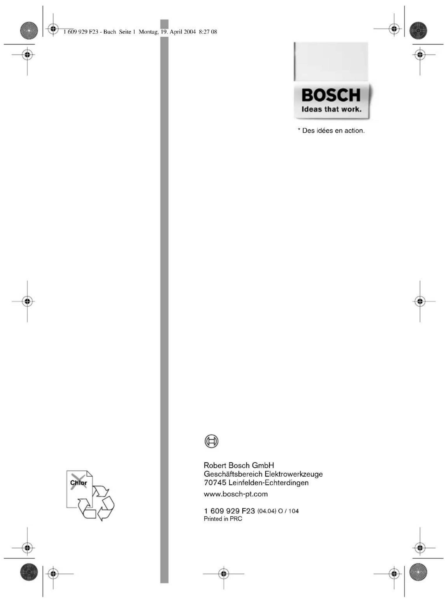
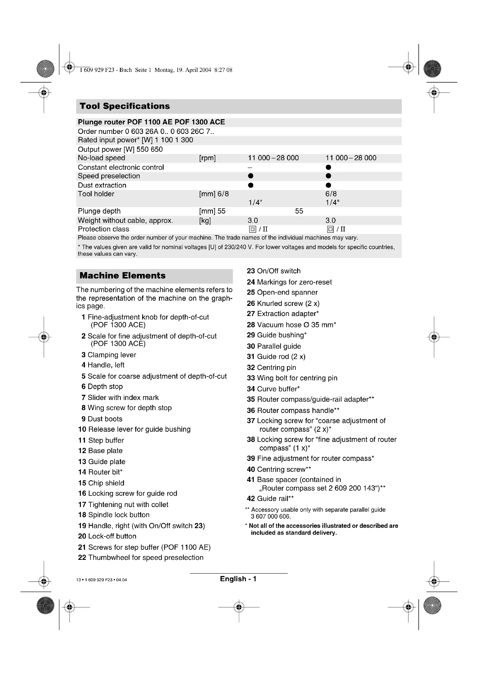
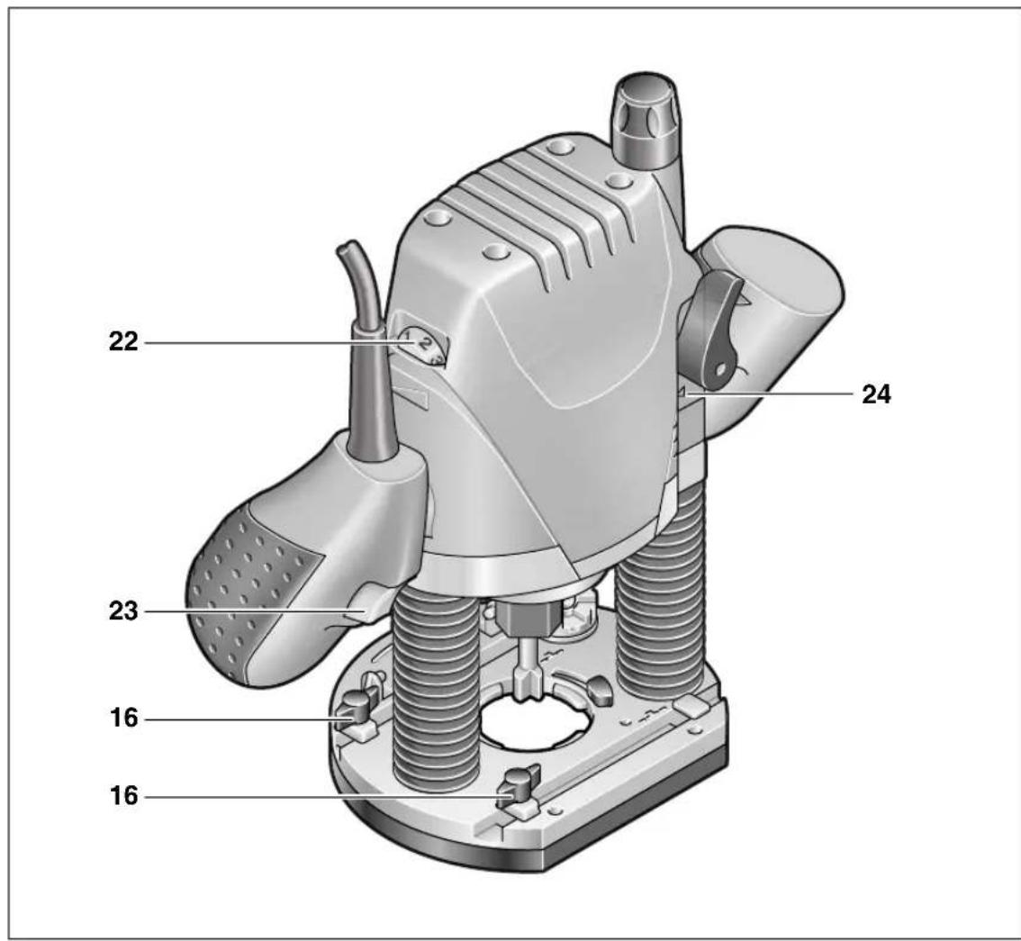
Machine Elements
The numbering of the machine elements refers to the representation of the machine on the graphics page.
1 Fine-adjustment knob for depth-of-cut (POF 1300 ACE)
2 Scale for fine adjustment of depth-of-cut (POF 1300 ACE)
3 Clamping lever
4 Handle, left
5 Scale for coarse adjustment of depth-of-cut
6 Depth stop
7 Slider with index mark
8 Wing screw for depth stop
9 Dust boots
10 Release lever for guide bushing
11 Step buffer
12 Base plate
13 Guide plate
14 Router bit*
15 Chip shield
16 Locking screw for guide rod
17 Tightening nut with collet
18 Spindle lock button
19 Handle, right (with On/Off switch 23)
20 Lock-off button
21 Screws for step buffer (POF 1100 AE)
22 Thumbwheel for speed preselection
23 On/Off switch
24 Markings for zero-reset
25 Open-end spanner
26 Knurled screw (2 x)
27 Extraction adapter*
28 Vacuum hose ∅ 35 mm*
29 Guide bushing*
30 Parallel guide
31 Guide rod (2 x)
32 Centring pin
33 Wing bolt for centring pin
34 Curve buffer*
35 Router compass/guide-rail adapter**
36 Router compass handle**
37 Locking screw for "coarse adjustment of router compass" (2 x)*
38 Locking screw for "fine adjustment of router compass" (1 x)*
39 Fine adjustment for router compass*
40 Centring screw**
41 Base spacer (contained in „Router compass set 2 609 200 143“)**
42 Guide rail**
** Accessory usable only with separate parallel guide 3 607 000 606.
* Not all of the accessories illustrated or described are included as standard delivery.
Intended Use
The machine is intended for routing grooves, edges, profiles and elongated holes as well as copy routing in wood, plastic and light building materials, while resting firmly on the workpiece. With reduced speed and with appropriate routing bits, non-ferrous alloys can also be machined.

For Your Safety
Working safely with this machine is possible only when the operating and safety information are read completely and the instructions contained therein are strictly followed. In addition, the general safety notes in the enclosed booklet must be observed. Before using for the first time, ask for a practical demonstration.
■Wear protective glasses and hearing protection.
■Wear sturdy shoes.
■For long hair, wear hair protection. Work only with closely fitting clothes.
If the mains cable is damaged or cut through while working, do not touch the cable but immediately pull the mains plug. Never use the machine with a damaged cable.
■Connect machines that are used in the open via a residual current device (RCD) with an actuating current of 30 mA maximum. Do not operate the machine in rain or moisture.
■Always direct the cable to the rear away from the machine.
■Use appropriate detectors to determine if utility lines are hidden in the work area or call the local utility company for assistance.
Contact with electric lines can lead to fire and electric shock. Damaging a gas line can lead to explosion. Penetrating a water line causes property damage or may cause an electric shock.
■Hold the power tool only by the insulated gripping surfaces, when performing an operation where the cutting tool may run into hidden wiring or its own cord.
Contact with a "live" wire will make exposed metal parts of the tool "live" and shock the operator.
■When working with the machine, always hold it firmly with both hands and provide for a secure stance.
■Secure the workpiece. A workpiece clamped with clamping devices or in a vice is held more secure than by hand.
■Apply the machine to the workpiece only when switched on.
■Before putting into operation, check the routing tool for firm seating.
■Never route over metal objects such as nails or screws.
■Keep hands away from rotating router bit.
■After finishing work, guide the machine back into the upper starting position by actuating the clamping lever and switch the machine off.
■Always switch the machine off and wait until it has come to a standstill before placing it down.
■Protect tools from impact and shock.
■Never allow children to use the machine.
■Bosch is only able to ensure perfect operation of the machine if the original accessories intended for it are used.
Inserting a Router Bit
Router Bit Selection
Depending on processing and application, router bits are available in the most different designs and qualities:
Router bits made of high speed steel (HSS) are suitable for the machining of soft materials, e. g. soft wood and plastic.
Carbide tipped router bits (HM) are particularly suitable for hard and abrasive materials, e. g. hard wood and aluminium.

Use only routing tools with an allowable speed matching at least the highest no-load speed of the machine.
The shank diameter of the router bit must correspond with the rated diameter of the tool holder (collet).
Original router bits from the extensive Bosch accessories program are available at your specialist shop.
Inserting Router Bits (see figure A)
■Before any work on the machine itself, pull the mains plug.
■It is recommended to wear protective gloves when inserting or replacing router bits.
Fold down chip shield 15.
Press spindle lock button 18 and keep depressed. If required, turn the spindle by hand until the lock engages.
■Press the spindle lock button only when at a standstill.
Insert router bit. The shank of the router bit must be inserted at least 20 mm (shank length).
Tighten the tightening nut 17 with the open-end spanner 25 (size 19 mm). Release the spindle lock button 18.
Fold up chip shield 15.

Do not tighten the tightening nut of the collet without a router bit inserted.
Dust/Chip Extraction
■The dust that is produced while working can be detrimental to health, inflammable or explosive. Suitable safety measures are required.
Examples: Some dusts are regarded as carcinogenic. Use suitable dust/chip extraction and wear a dust respirator.
■Dust from light alloys can burn or explode. Always keep the workplace clean, as blends of materials are particularly dangerous.
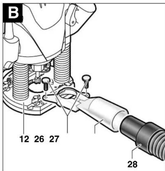
Mounting the Extraction Adapter (see figure B)
Press the chip shield 15 together at the holding fixture on the base plate and remove it.
Fasten dust-collection adapter 27 to base plate 12 with both knurled screws 26 and connect vac via suction hose 28 (accessory).

When mounting the extraction adapter, ensure correct mounting position!
For dust extraction, the 35-mm-∅ vacuum hose 28 can be connected directly to the extraction adapter.
Clean the extraction adapter 27 regularly to ensure optimum dust extraction at all times.
The machine can be plugged directly into the receptacle of a Bosch all-purpose vacuum cleaner with remote starting control. The vacuum cleaner starts automatically when the machine is switched on.
The vacuum cleaner must be suitable for the material to be worked.
When vacuuming dry dust that is especially detrimental to health or carcinogenic, use a special vacuum cleaner.
Initial Operation
Observe correct mains voltage: The voltage of the power source must agree with the voltage specified on the nameplate of the machine. Equipment marked with 230 V can also be connected to 220 V.
Switching On and Off
For starting operation of the machine, actuate the lock-off button 20 first, and then press and hold the On/Off switch 23 afterwards.
POF 1300 ACE: A lamp lights out the routing.
To switch off the machine, release the On/Off switch 23.
POF 1300 ACE: The lamp slowly goes out.
Speed Preselection
The required speed can be preselected with the thumbwheel 22 (also while running).

1 - 2 = low speed
3 - 4 = medium speed
5 - 6 = high speed
The required speed is dependent on the material and can be determined by practical testing.
After longer periods of working at low speed, allow the machine to cool down by running it for approx. 3 minutes at maximum speed with no load.
Speed Table
Material Router bit-∅ Speed stages
Hardwood 4 – 10 mm 5 – 6
(Beech) 12 - 20 mm 3 - 4
$$ 2 2 - 4 0 \mathrm{mm} 1 - 2 $$
Softwood 4 – 10 mm 5 – 6
(Pine) 12 - 20 mm 3 - 6
$$ 2 2 - 4 0 \mathrm{mm} 1 - 3 $$
Particle board 4 – 10 mm 3 – 6
$$ 1 2 - 2 0 \mathrm{mm} 2 - 4 $$
$$ 2 2 - 4 0 \mathrm{mm} 1 - 3 $$
Plastic 4 – 15 mm 2 – 3
$$ 1 6 - 4 0 \mathrm{mm} 1 - 2 $$
Aluminium 4 – 15 mm 1 – 2
$$ 1 6 - 4 0 \mathrm{mm} 1 $$
The values shown in the chart are standard values. The necessary speed depends on the material and the operating conditions, and can be determined by practical testing.
Constant Electronic Control (POF 1300 ACE)
Constant electronic control holds the speed constant at no-load and under load, and ensures uniform working performance.
Setting the Depth-of-cut
Depending on the cutting operation, the depth-of-cut can be preset in several steps.

The adjustment of the depth-of-cut may only be carried out when the router is switched off.
Coarse Adjustment of the Depth-of-cut
- Place the router on the workpiece to be machined.
POF 1300 ACE: Set the fine adjustment for depth-of-cut in the center position with fine-adjustment knob 1; to do this, turn the fine-adjustment knob until the markings 24 on the backside of the router are in alignment, as shown.
Afterwards turn scale 2 to "0" (see figure C)
Set step buffer 11 to the lowest position; the buffer snaps-in noticeably.
POF 1100 AE: Set the screws for the step buffer 21 halfway in or out.
Set step buffer 11 to the lowest position; the buffer snaps-in noticeably. When fine adjustment of the depth-of-cut is desired, select one of the 3 steps that is fitted with the screw 21.
POF 1100 AE/POF 1300 ACE:
- Loosen locking screw 8, so that depth stop 6 can be moved freely.
- Release the clamping lever 3 by turning in clockwise direction and slowly lower the router until the router bit touches the surface of the workpiece. Lock the router in position by turning the clamping lever 3 in anticlockwise direction.
- Press depth stop 6 downwards until it touches the stop buffer 11. Press down slider 7 and set to "0".
- Adjust the depth stop 6 to the required routing depth and tighten the wing screw 8. It is important that the slider 7 is not adjusted afterwards.
- Release the clamping lever 3 and guide the router back up again.
The coarse adjustment of the depth-of-cut should be checked by a trial cut and corrected, if necessary.
Fine Adjustment of the Depth-of-cut (POF 1300 ACE)
After a trial cut, fine adjustment can be carried out by turning the fine adjustment knob 1 (1 scale mark = 0.1 mm/1 rotation = 2.0 mm). The maximum adjustment is approx. +/- 8 mm.
Example: Slide router upwards again and measure the depth-of-cut (set value = 10.0 mm; actual value = 9.8 mm).
- Lift up router and underlay guide plate 13 in such a manner that the router can plunge freely without the router bit touching the workpiece. Lower the router again until the depth stop 6 touches the step buffer 11.
- Afterwards set scale 2 to "0".
- Loosen wing screw 8.
- With the fine adjustment 1, advance the depth-of-cut in clockwise direction by 0.2mm/ 2 scale marks (= difference between required value and actual value).
- Retighten wing screw 8 again.
- Slide router upwards again and check depth-of-cut by carrying out another trial cut.
After setting the depth-of-cut, the position of the index mark 7 on the depth stop should not be changed anymore so that the currently adjusted setting can always be read off of scale 5.
Fine Adjustment of the Depth-of-cut (POF 1100 AE)
With the step buffer 11, up to three different routing depths can be preset. Adjustment is carried out according to the previously described procedure, with the difference that by screwing in or out the screws for the step buffer 21, the height clearance of the stops, in reference to each other, can be changed.
Usage of the Step Buffer
a) Dividing the cutting procedure in several steps
For deep cuts, it is recommended to carry out several cuts, each with less material removal. By using the step buffer 11, the cutting process can be divided into several steps.
Set the required depth-of-cut with the lowest step of the step buffer. Afterwards, the higher steps can be used for the first two cuts.
b) Pre-adjustment of varying depth-of-cuts
If several different depth-of-cuts are required for the machining of a workpiece, these can also be pre-adjusted by using the step buffer 11.
Operating Instructions
Direction of Feed
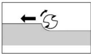
natural_image
Simple diagram showing a wave interacting with a surface, no text or symbols presentThe feed motion of the router must always be carried out against the rotation direction of the router bit (up-grinding).
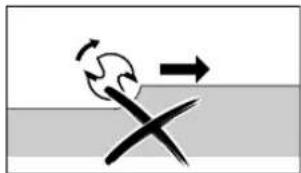
natural_image
Diagram showing a cross-shaped object with motion arrows above and below a horizontal surface (no text or symbols)When milling in the direction with the rotation of the router bit (down-cutting), the router can break loose, eliminating control by the user.
Routing Process
Adjust the depth-of-cut as previously described.
Place the router on the workpiece and switch on.
Release the clamping lever 3 by turning in clockwise direction and slowly lower the router until the depth stop 6 runs against the workpiece. Lock the router in position by turning the clamping lever 3 in anticlockwise direction. Cary out the cutting procedure with uniform feed.
After finishing the cutting process, slide the router upwards again and switch off.
Routing with Guide Bushing
The guide bushing 29 enables template and pattern routing on workpieces.
Inserting guide bushing 29 (see figure D)
Insert guide bushing 29 in the bottom of the guide plate 13 by actuating the locking lever 10. Ensure that the encoding keys clearly engage in the grooves of the guide bushing.
Routing Process (see figure E)

Choose a router bit with a smaller diameter than the inner diameter of the guide bushing.
Set the router with guide bushing 29 against the template. Release the clamping lever 3 by turning in clockwise direction and slowly lower the router toward the workpiece until the adjusted depth-of-cut is reached.
Guide router with projecting guide bushing along the template, applying light sideward pressure.
Note: The template must have a minimum thickness of 8 mm, due to the projecting height of the guide bushing.
Routing with Guide Rail (see figure F)
Fasten a suitable guide rail with an appropriate clamping device (screw clamp) to the workpiece.
Guide the flattened side of the guide plate along the guide rail.
Note the direction of feed:

To avoid the router from "running off" of the guide rail, it is important that the router is led as shown.
Shaping or Molding Applications
For shaping or molding applications without the use of a parallel guide, the router must be equipped with a pilot or a ball bearing.
Lead the router sidewards to the workpiece and allow router bit to engage until the pilot or the ball bearing of the router reach the corner of the workpiece being machined. Guide the router alongside the workpiece corner using both hands, ensuring proper seating of the base plate. Too much pressure can damage the edge of the workpiece.
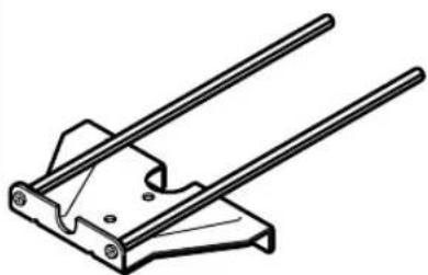
Routing with Parallel Guide (Accessory – see figures G) H
Slide the parallel guide 30 with the guide rods 31 into the base plate 12 and tighten at the required measure with the wing bolts 16.
Guide the machine with uniform feed and sideward pressure on the parallel guide 30 along the edge of the workpiece.
Routing Circular Arc Profiles (see figures Ⅰ) K
Reverse the parallel guide 30 (facing surfaces point upwards) and insert the guide rods into the base plate 12. Fasten centring pin 32 to parallel guide (through hole) with wing bolt 33.
Puncture centring pin into marked centre of the circular arc and guide router with consistent feed across the workpiece surface.
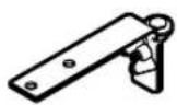
Routing with the Curve Buffer (see figures L) M
Slide the parallel guide 30 with the guide rods 31 into the base plate 12. Fasten the curve buffer 34 with the guide roller mounted to the parallel guide 30.
Guide the machine along the workpiece edge with light sideward pressure.
Routing with the Router Compass (Accessory – see figure N)
Use the router compass/guide rail adapter 35 (accessory) for circular routing jobs.
Mount the router compass as shown in the figure.
Screw pointed centring screw 40 in thread. Insert the point of the centring screw in the centre of the circular arc to be milled and ensure that it engages in the workpiece surface.
Coarse-adjust the required radius by positioning the router compass, then tighten the locking screws 37 and 38.
After loosening the locking screw 37, the router compass can be reset with the fine adjustment knob 39 (1 scale mark = 0.1 mm/1 rotation = 2.0 mm).
Lead the router over the workpiece, holding the router with the right handle 19 and the additional router compass handle 36.
Routing with Guide Rail (Accessory – see figure 0)
Working with the guide rail 42 is possible only with use of the guide-rail adapter 35 (accessory).
Straight routing cuts are to be carried out with help of the guide rail 42 (accessory).
For this, always use the base spacer 41 (accessory) to compensate the height difference.
Mount the guide-rail adapter 35 with the guide rods 31.
Place the guide rail on the workpiece and mount with a suitable clamping device (e. g. screw clamp).
Place the router with guide-rail adapter 35 on the guide rail.
Maintenance and Cleaning
■Before any work on the machine itself, pull the mains plug.
■For safe and proper working, always keep the machine and the ventilation slots clean.
If the machine should fail despite the care taken in manufacturing and testing procedures, repair should be carried out by an after-sales service centre for Bosch power tools.
In all correspondence and spare parts orders, please always include the 10-digit order number given on the nameplate of the machine.
WARNING! Important instructions for connecting a new 3-pin plug to the 2-wire cable.
The wires in the cable are coloured according to the following code:

text_image
strain relief live = brown neutral = blue To be fitted by qualified professional onlyDo not connect the blue or brown wire to the earth terminal of the plug.
Important: If for any reason the moulded plug is removed from the cable of this machine, it must be disposed of safely.
Environmental Protection

Recycle raw materials instead of disposing as waste
The machine, accessories and packaging should be sorted for environmental-friendly recycling.
These instructions are printed on recycled paper manufactured without chlorine.
The plastic components are labelled for categorized recycling.
Noise/Vibration Information
Measured values determined according to EN 60 745.
Typically the A-weighted noise levels of the machine are: sound pressure level 95 dB (A); sound power level 106 dB (A). Measurement
uncertainty K = 3 dB.
Wear hearing protection!
The typical hand/arm vibration is below 2.5 m/s ^4 .
Service and
Customer Assistance
Exploded views and information on spare parts can be found under: www.bosch-pt.com
Great Britain
Robert Bosch Ltd. (B.S.C.)
P.O. Box 98
Broadwater Park
North Orbital Road
Denham-Uxbridge
Middlesex UB 9 5HJ
©Service.... +44 (0) 18 95 / 83 87 82
©Advice line ....+44 (0) 18 95 / 83 87 91
Fax....+44 (0) 18 95 / 83 87 89
Ireland
Beaver Distribution Ltd.
Greenhills Road
Tallaght-Dublin 24
©Service....+353 (0)1 / 414 9400
Fax....+353 (0)1 / 459 8030
Australia
Robert Bosch Australia Ltd.
RBAU/SPT2
1555 Centre Road
P.O. Box 66 Clayton
3168 Clayton/Victoria
① +61 (0)1 / 800 804 777
Fax....+61 (0)1 / 800 819 520
www.bosch.com.au
E-Mail: CustomerSupportSPT@au.bosch.com
New Zealand
Robert Bosch Limited
14-16 Constellation Drive
Mairangi Bay
Auckland
New Zealand
CE Declaration of Conformity
We declare under our sole responsibility that this product is in conformity with the following standards or standardization documents: EN 60 745 according to the provisions of the directives 89/336/EEC, 98/37/EC.
Dr. Egbert Schneider Dr. Eckerhard Strötgen
Senior Vice President Head of Product
Engineering Certification
Subject to change without notice
Constant-Electronic (POF 1300 ACE)
natural_image
Simple diagram showing a wave interacting with a surface, no text or symbols presentnatural_image
Diagram showing a hand holding a curved object above a surface with an arrow indicating motion (no text or symbols)Robert Bosch France S.A.
Service Après-vente/Outillage
Senior Vice President Head of Product
Engineering Certification
ppa. Jhaka i.v. Nuoyen
Portaútiles [mm] 6/8 6/8 1/4" 1/4"
Peso sin cable de red, aprox. [kg] 3,0 3,0
natural_image
Simple diagram showing a wave interacting with a surface, no text or symbols presentnatural_image
Diagram showing a hand holding a curved object above a water surface with an arrow indicating motion (no text or symbols)Senior Vice President Head of Product
Engineering Certification
ppa. Amaka i.v. Nuoyen
Constant-Electronic (POF 1300 ACE)
natural_image
Simple diagram showing a wave interacting with a surface, no text or symbols presentnatural_image
Diagram showing a cross-shaped object interacting with a horizontal surface, with an arrow indicating direction (no text or symbols)Fresar arcos (veja as figuras I) K
Senior Vice President Head of Product
Engineering Certification
ppa. A##ca i.v. Mo#gen
Constant-Electronic (POF 1300 ACE)
natural_image
Simple diagram showing a wave interacting with a surface, no text or symbols presentnatural_image
Diagram showing a cross-shaped object with motion arrows above and below a horizontal surface (no text or symbols)Senior Vice President Head of Product
Engineering Certification
ppa. Jhaka i.v. Miojen
Constant-electronic (POF 1300 ACE)
natural_image
Simple diagram showing a wave interacting with a surface, no text or symbols presentnatural_image
Diagram showing a cross-shaped object with motion arrows above and below a horizontal surface (no text or symbols)Senior Vice President Head of Product
Engineering Certification
ppa. Abuca i.v. Moyen
natural_image
Simple diagram showing a wave interacting with a surface, no text or symbols presentnatural_image
Diagram showing a hand holding a curved object above a surface with an arrow indicating motion (no text or symbols)Senior Vice President Head of Product
Engineering Certification
ppa. Abuca i.v. Moyen
27 Utsugningsadapter*
28 Sugslang ∅ 35 mm*
29 Kopierhylsa*
30 Parallellanslag
31 Styrstång (2 x)
32 Centrerdorn
(Tall) 12 - 20 mm 3 - 6
22 - 40 mm 1 - 3
Spånplatta 4 – 10 mm 3–6
12 - 20 mm 2 - 4
22 - 40 mm 1 - 3
Plast 4 - 15 mm 2 - 3
16 - 40 mm 1 - 2
Aluminium
4 - 15 mm 1 - 2
16 - 40 mm 1
natural_image
Simple diagram showing a wave interacting with a surface, no text or symbols presentnatural_image
Diagram showing a hand holding a curved object above a surface with an arrow indicating motion (no text or symbols)Senior Vice President Head of Product
Engineering Certification
ppa. A##ca i.v. M#y##
2 Skala fresedybde-fininnstilling (POF 1300 ACE)
3 Spennarm
4 Venstre håndtak
5 Skala fresedybde-grovinnstilling
6 Dybdeanlegg
Sponplater 4 – 10 mm 3–6
12-20mm2-4
22 - 40 mm 1 - 3
natural_image
Simple diagram showing a wave interacting with a surface, no text or symbols presentnatural_image
Diagram showing a hand holding a curved object above a surface with an arrow indicating motion (no text or symbols)Senior Vice President Head of Product
Engineering Certification

i.v. Puoyen
natural_image
Simple diagram showing a wave interacting with a surface, no text or symbols presentnatural_image
Diagram showing a curved arrow and a cross on a horizontal surface, with no text or symbols present.Senior Vice President Head of Product
Engineering Certification
ppa. A##u i.v. N#y##
natural_image
Simple diagram showing a curved object with motion arrows, resting on a horizontal surface (no text or symbols)natural_image
Diagram showing a cross-shaped object interacting with a surface, with an arrow indicating direction (no text or symbols)Dr. Egbert Schneider Dr. Eckerhard Strötgen Senior Vice President Head of Product Engineering Certification
ppa. Amata i.v. Noyen
natural_image
Simple diagram showing a wave interacting with a surface, no text or symbols presentnatural_image
Diagram showing a hand gesture with an arrow and a cross on a surface (no text or symbols)Bosch San. ve Tic. A.S.
Ahi Evran Cad. No:1 Kat:22
Polaris Plaza
80670 Maslak/Istanbul
① +90 (0)212 / 335 06 00
Faks....+90 (0)212 / 346 00 48-49
Çevre koruma

Dr. Egbert Schneider Dr. Eckerhard Strötgen Senior Vice President Head of Product Engineering Certification
ppa. Amata i.v. Moyen
natural_image
Technical line drawing of a mechanical component with no visible text or symbols1 609 203 M87
natural_image
Technical line drawing of a mechanical clamp or bracket component (no text or symbols)1 609 203 M85
1 609 203 M86

text_image
Ø mm 8 2 609 200 144 (L = 0,6 m) 8 3 607 000 606 2 607 001 161 8 2 609 200 143 2 602 317 030 (L = 0,7 m) 2 609 317 031 (L = 1,4 m) Ø 35 mm 3 m 2 607 002 149 PAS 11-21/ 5 m 2 607 002 150 12-27/12-27 F98·1 609 929 F23·04.04