RLT30CESC - String trimmers RYOBI - Free user manual and instructions
Find the device manual for free RLT30CESC RYOBI in PDF.
| Brand | RYOBI |
| Model | RLT30CESC |
| Product type | Petrol strimmer |
| Engine type | 2-stroke engine, single cylinder |
| Displacement | 30 cm³ |
| Maximum power | 0.75 kW (conforms to ISO 8893) |
| Maximum shaft speed | 12,000 min⁻¹ |
| Idle speed | 2,800 - 3,800 min⁻¹ |
| Fuel | Unleaded 91 octane petrol + synthetic 2-stroke oil (ratio 50:1) |
| Fuel tank capacity | 415 cm³ (0.415 L) |
| Cutting width | 432 mm |
| Line diameter | 2.4 mm (single line) |
| Cutting head type | Reel Easy™ (bump feed) |
| Weight (without fuel or accessory) | 5.02 kg |
| Measured sound power level | 110.7 dB(A) |
| Guaranteed sound power level | 112 dB(A) |
| Starting system | Manual recoil starter with primer bulb and choke |
| Safety equipment | Grass deflector, eye and hearing protection recommended, emergency stop |
| Routine maintenance | Air filter cleaning, spark plug replacement (Champion RCJ-6Y), fuel drain for storage |
| Warranty | 24 months (extension possible via online registration) |
Frequently Asked Questions - RLT30CESC RYOBI
User questions about RLT30CESC RYOBI
0 question about this device. Answer the ones you know or ask your own.
Ask a new question about this device
Download the instructions for your String trimmers in PDF format for free! Find your manual RLT30CESC - RYOBI and take your electronic device back in hand. On this page are published all the documents necessary for the use of your device. RLT30CESC by RYOBI.
USER MANUAL RLT30CESC RYOBI
It is essential that you read the instructions in this manual before assembling, maintaining and operating this machine.
Subject to technical modifications.

| Important! | It is essential that you read the instructions in this manual before operating this machine. |
| Attention! | Il est indispensable que vous lisiez les instructions contenues dans ce manuel avant la mise en service de l'appareil. |
| Achtung! | Bitte loosen Sie unbedingt vor Inbetriebnahme die Hinweise dieser Bedienungsanleitung. |
| Àtenzione! | Es imprescindibile que lea las instrucciones de este manual antes de la puesta en service. |
| Attenzione! | Prima di procedere alla messa in funzione, è indispensable leggere attendamente le istruzioni contenute nel manuale. |
| Let op! | Het is van essentieel belang dat u de instructies in deze gebruiksaanwijzing goed leest voordat u de machine gaat gebruiken. |
| Atença! | É indispensable que leia as instruções deste manual antes de'utilizar a máquina. |
| OBS! | Denne brugervejledning skal gennemlæses inden maskinen tage i brug. |
| Observeral | Det ar nõdvändigt att lasa instruktionerna ienna bruksanvising innan användning. |
| Huomio! | On ehdottoman välttämäntä lukea tassä käytöohjeessa annetut oheet ennen käytöönottoa. |
| Advarsell | Det er meget viktig at du leser dette brukerveiledningen før du tar maskinen i bruk. |
| BHMannne! | Eine c60kòn i 3anyckOM INCTpymèNTA H60xOIMMo O3hakOMMbTcR C INHCTpyKμηe NOKCπnyatauM. |
| Uwaga! | Przed przystapieniem do uzytkowania tego urzadzenia, nalezy koniecznie zapoznać sie z zaleceniami zawartymi w niniejszym podrçcniku. |
| Duležite upozornénil | Nepoužívejte tento pfiistroj dǐlive, než si pfečete polkyny uvedeni v totem návodu. |
| Figyelem! | Feltétlenül fontos, hogy a jelen hasznalati utmutatóban foglalt elöirásokat az üzembe helyezés elott elolvassa! |
| Atenți! | Este esentjal sà citiji instructcjunile din acest manual ònaite de operarea acestui aparat. |
| Uzmanibul | Svarīgi, láj ius pirms mašinas darbinăsanas izlasitu instrukcjas šajr rokasgrāmata. |
| Démesio! | Priës pradédami eksploatuoti šj prietaisa, svarbu, kad perskáitytumēt siose instrukcjose pateiktus nurodymus. |
| Tähtis! | Enne trelli kasutama hakkamist tuleb käesolevas juhendis esitatud juhised kindlasti läbi lugeda. |
| Upozorenje! | Neophodno je da procitate ove upute prije uporabe ovog uredaja. |
| Pomembnol! | Pred uporabo tega stroja, obvezno preberite navodila iz tega priročnika. |
| Duležite! | Pre prácu s týmto zariadenim je duležite, abi ste si prečitali polkyny v totem návode. |
| Baxhno! | Öt İ3KNHHTENH BAXHOCET e Damage prechete INCTpyKμηITE B TOBA pykOBODCTBO, İpreni da δopabinte c Taşni MaùnHa. |
Subject to technical modifications / Sous reserve de modifications techniques / Technische Änderungen vorbehalten / Bajo reserva de modificaciones tecnicas / Con riserva di eventuali modifiche tecniche / Technische wizzigingen voorbehonden / Com reserva de modificações tecnicas / Med forbeshor for tekniske endringer / Med forbehall for tekniska andringar / Tekniset mutokset varataan / Med forbeshor om tekniske endringer / Moryt 6bTbBHeCHebTexHneckne H3MeHnna / Z zastrzezeniem modyfikacji technicznych / Zmyny technickych udaju vyhrazeny / A muszaki modositas jogat fenntartjuk / Sub rezerva modifica'ilor tehnice / Paturam tiesibas mainit tehniskos raksturlielemus / Pasiliekant teise daryi techninius pakeitimus / Tehnilised muudatused voimalikud / Podloeno tehniékim promjenama / Tehnicne spremembe dopuscene / Pravo na technické zmeny je vyhradene / Полпеки на Тхнчecк модфikaци
EN Some regions have regulations that restrict the use of the product to some operations. Check with your local authority for advice.
FR La législation de certaines régions restreint l'utilisation du produit à certaines opérations. Contactez les autorités locales pour de plus amples informations.
DE In einigen Regionen konnen Vorschriften die Benutzung these Products auf eine Tätigkeiten beschränken. Lassen Sie sich von ihrer ortlichen Behörde beraten.
ES Algunas regiones tienen normativas que restringen el uso del producto paraellas operaciones.Consulte con sus autoridades locales.
IT In alcune regioni norme specifiche limitano l'utilizzo del prodotto ad alcune operazioni. Controllare con le autorità locali per averere ulteriori informazioni a riguardo.
NL In enkele streken gelden regels die het gebruik van het product tot enkele handelingen beperken. Raadpleeg uw gemeentebestuur voor advies.
PT Algumas regioes tem normas que restrimgem o uso do produits paraalgumas operacoes.Consulte as autoridades locais.
DA Nogle omrader har regler, som begrenser brugen af produktet til visse formal. Forhargid hos de lokale myndigheder.
SV En del regioner har regelverk som begrainsar produktens anvandning till vissa functior. Kontrollera med lokala myndigheter.
Fi Joillain alueilla vallitsee saadoksi, jotka rajoittavat taman tuotteen kayttoa joissain toiminnoissa. Pyyda paikallisila viranomaisilta neuvoa.
NO Visse regioner har forskritter som begrenser bruken av produktet til definerte operasjoner. Sjekk hos lokale myndigheter for rad.
RU B HeKOTopbIX perHOH cxueCTByIOT orpaHnueHna HcNoJIb3OBAHne HeKOTopbIX onepaCn C daHHbIM yCTpOeCTBOM. ObaaTecb 3a HOpMaueB M MeCThBe Bmactn.
PL W niedtorych regionach obwauzujprzepisy ograniczajce uzywanie produktu w przypadku okreslonych dzialan. Informace na ten temat moza uzyskac w lokalnych urzedach.
CS Mistni pr edpisy mohou omezoval pouziti vyrobku. OveTe si u svheo organu mistni spravy toto naizeni.
HU Egyes regiokban oyan eloiraksok erenyesek, amelyek krolatozzak a termek bizonyos mveletekre valo hasnalatat. Tovabbi informacioert forduljon a helyi onkormanyzathoz.
RO Unele regiuni au reglementari care restrictioneazăutilizarea produsului la unele operatjuni. Cereti sfatul autoritatei locale.
LV Dažos regionos pastav noteikumi, kas ierobezo darbības, kurām produits ir izmantojams. Lai uzzinatu vairak, konsultejieties ar vietjām iestādēm.
LT Kai kuriuose regionuose sio gaminio naudiojima tam tikriems darbams apriboja gialojantys jstatymai. Del patarimukreipkites j vietines valdios institucija.
ET Moneedes piirkondades on seadused, mis piiravad toote kasutamist teatud toode tegemiseks. Lisateavet saate kohlikust omavalitsusest.
HR Neke regije imaju pravila koja ograničavaju korištenje proizvoda za neke radove. Provjerite kod lokalmih tjija za savjet.
SL Vnekaterih regijah predispisi omejujejo uporabo izdelka na dolocene namene. Za nasvet se obrnite na lokalne oblasti.
SK Niektoré regiony maju nariadenia, ktoré obmedzuju pouitie produktu na urcité operatie. Poradte sa s miestnym uradom.
BG B HnKo n pmoHn mpa3nope6n, orpaHnuaBaun 3nO3BaHeTo Ha npOdykTa Do onpeJeeneH onepaun. NOnckaiTe CbbET OT MeCTHNTe Bnactn.


CHARACTERISTIQUES PRODUIT
Poids
English(Original instructions)
SYMBOLS
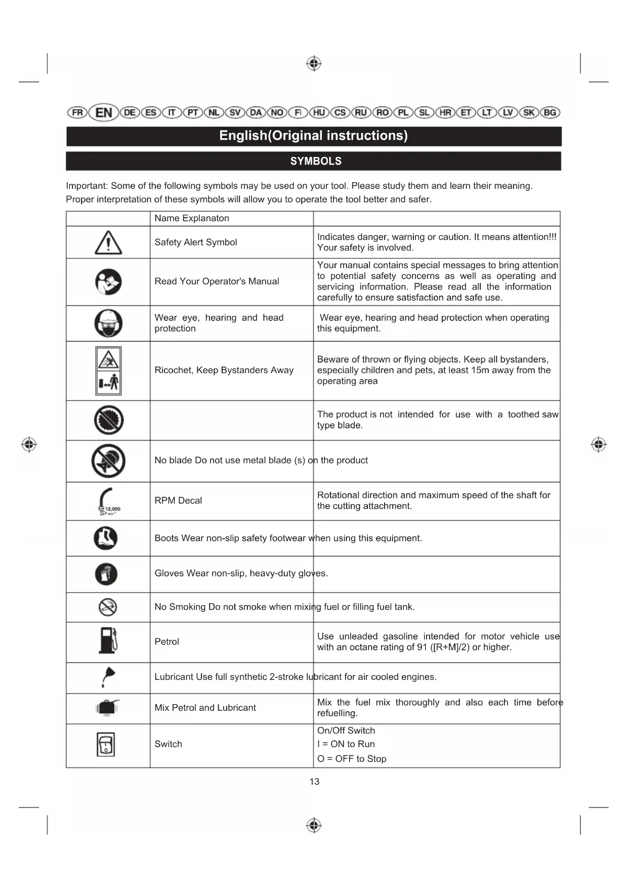
Important: Some of the following symbols may be used on your tool. Please study them and learn their meaning.
Proper interpretation of these symbols will allow you to operate the tool better and safer.
| Name Explanation | ||
| Safety Alert Symbol | Indicates danger, warning or caution. It means attention!!! Your safety is involved. | |
| Read Your Operator's Manual | Your manual contains special messages to bring attention to potential safety concerns as well as operating and servicing information. Please read all the information carefully to ensure satisfaction and safe use. | |
| Wear eye, hearing and head protection | Wear eye, hearing and head protection when operating this equipment. | |
| Ricochet, Keep Bystanders Away | Beware of thrown or flying objects. Keep all bystanders, especially children and pets, at least 15m away from the operating area | |
| The product is not intended for use with a toothed saw type blade. | ||
| No blade Do not use metal blade (s) on the product | ||
| RPM Decal | Rotational direction and maximum speed of the shaft for the cutting attachment. | |
| Boots Wear non-slip safety footwear when using this equipment. | ||
| Gloves Wear non-slip, heavy-duty gloves. | ||
| No Smoking Do not smoke when mixing fuel or filling fuel tank. | ||
| Petrol | Use unleaded gasoline intended for motor vehicle use with an octane rating of 91 ([R+M]/2) or higher. | |
| Lubricant Use full synthetic 2-stroke lubricant for air cooled engines. | ||
| Mix Petrol and Lubricant | Mix the fuel mix thoroughly and also each time before refuelling. | |
| Switch | On/Off Switch I = ON to Run O = OFF to Stop | |
FRENDEESITPTNLSVDANOFHUCSRUROPLSLHRETLTLVSKBG
English(Original instructions)
| Keep hands away from blades. | ||
| Run position | ||
| Set the choke lever to "FULL" choke position. | ||
| Set the choke lever to "HALF" choke position. | ||
| Set the ignition switch to the "I" (ON) position. | ||
| x10 | Press the primer bulb 10 times. | |
| Pull the starter rope to start. | ||
| Squeeze the throttle lock and throttle trigger to run. | ||
| Wait 10 seconds. | ||
| To stop the engine, move the ignition switch to the "stop position". | ||
| CE | Conforms to all regulatory standards in the country in the EU where the product is purchased.. | |
| EAC | EurAsian Conformity Mark | |
| Ukrainian mark of conformity | ||
| 112 | Guaranteed sound power level is 112 dB. |
The following signal words and meanings are intended to explain the levels of risk associated with the product.
| SYMBOLS SIGNAL | NAL MEANING | |
| ! | DANGER | Indicates an imminently hazardous situation, which, if not avoided, will result in death or serious injury. |
| ! | WARNING | Indicates a potentially hazardous situation, which, if not avoided, could result in death or serious injury. |
| ! | CAUTION | Indicates a potentially hazardous situation, which, if not avoided, may result in minor or moderate injury. |
| CAUTION | (Without Safety Alert Symbol) Indicates a situation that may result in property damage. |
FRENDEESITPTNLSVDANOFHUCSRUROPLSLHRETLTLVSKBG
English(Original instructions)
Thank you for buying a Ryobi trimmer.
Your new trimmer has been engineered and manufactured to Ryobi's high standard for dependability, ease of operation, and operator safety. Properly cared for, it will give you years of rugged, trouble-free performance.
INTENDED USE
The product is only intended for use outdoors in a well ventilated area.
The product is intended for cutting long grass, pulpy weed and similar vegetation at or about ground level. The product should not be used to cut or trim hedges, bushes or other vegetation where the cutting plane is not parallel to the ground surface.

WARNING
To reduce the risk of injury, the user must read and understand the operator's manual.

WARNING
Do not attempt to operate the product until you have read thoroughly and understood completely all instructions, safety rules etc contained in this manual. Failure to comply may result in accidents involving fire, electric shock or serious personal injury. Save operator's manual and review frequently for continuing safe operation, and instructing others who may use this tool.
READ ALL INSTRUCTIONS.
GENERAL SAFETY RULES
For safe operation, read and understand all instructions before using the product. Follow all safety instructions. Failure to follow all safety instructions listed below, can result in serious personal injury.
Some regions have regulations that restrict the use of the product. Check with your local authority for advice.
- Do not allow children or untrained individuals to use the product.
- Never start or run the engine in a closed or poorly ventilated area; breathing exhaust fumes can kill.
- Clear the work area before each use. Remove all objects such as rocks, broken glass, nails, wire, or string which can be thrown or become entangled in the bump head.
Wear full eye and hearing protection while operating the product.
Wear heavy long pants, boots, and gloves. Do not wear loose fitting clothing, short pants, jewellery of any
kind, or use with bare feet.
-
Secure long hair so it is above shoulder level to prevent entanglement in any moving parts.
-
Keep all bystanders, children, and pets at least 15 m away.
-
Do not operate the product when you are tired, ill, or under the influence of alcohol, drugs, or medication.
Do not operate in poor lighting. -
Keep firm footing and balance. Do not overreach. Overreaching can result in loss of balance or exposure to hot surfaces.
-
Keep all parts of your body away from any moving part.
- Do not touch area around the muffler or cylinder of the product, these parts get hot from operation.
Always stop the engine and remove the spark plug wire before making any adjustments or repairs except for carburetor adjustments.
Inspect the product before each use for loose fasteners, fuel leaks, etc. Replace any damaged parts before use.
It has been reported that vibrations from hand-held tools may contribute to a condition called Raynaud's Syndrome in certain individuals. Symptoms may include tingling, numbness and blanching of the fingers, usually apparent upon exposure to cold. Hereditary factors, exposure to cold and dampness, diet, smoking and work practices are all thought to contribute to the development of these symptoms.
It is presently unknown what, if any, vibrations or extent of exposure may contribute to the condition. There are measures that can be taken by the operator to possibly reduce the effects of vibration:
a) Keep your body warm in cold weather. When operating the product wear gloves to keep the hands and wrists warm. It is reported that cold weather is a major factor contributing to Raynaud's Syndrome.
b) After each period of operation, exercise to increase blood circulation.
c) Take frequent work breaks. Limit the amount of exposure per day.
If you experience any of the symptoms of this condition, immediately discontinue use and see your physician about these symptoms.
- Keep the tool well maintained, fasteners tightened and worn parts replaced.
- Mix and store fuel in a container approved for fuel.
Mix fuel outdoors where there are no sparks or flames. Wipe up any fuel spillage. Move 9 m away from
FRENDEESITPTNLSVDANOFHUCSRUROPLSLHRETLTLVSKBG
English(Original instructions)
refueling site before starting engine.
- Stop the engine and allow to cool before refueling or storing the product.
- Allow the engine to cool; empty the fuel tank and secure the product from moving before transporting in a vehicle. Secure the unit during transport to prevent damage or injury.
- Debris, when hit by the line, can travel significant distances. Remove debris from the working area before operating.
- When operating the product, wear hearing protection.
- Operating similar tools nearby increases risk of injury.
Use of hearing protection reduces the ability to hear warnings (shouts or alarms). The operator must pay extra attention to what is going on in the working area.
If working in an area where there is a risk of falling objects, head protection must be worn.

WARNING
Inspection after dropping or other impacts: Thoroughly inspect the product and identify any affections or damage with it. Any part that is damaged should be properly repaired or replaced by an authorized service centre.

WARNING
Injuries may be caused, or aggravated, by prolonged use of a tool. When using any tool for prolonged periods, ensure you take regular breaks.
TRIMMER SAFETY WARNINGS
- Replace the bump head if cracked, chipped, or damaged in any way. Be sure the bump head is properly installed and securely fastened. Failure to do so can cause serious injury.
Make sure all guards, straps, deflectors and handles are properly and securely attached.
Use only the manufacturer's replacement line in the cutting head. Do not use any other cutting attachment. Failure to do so can result in serious personal injury. - Never operate unit without the safety guard in place and in good condition.
- Maintain a firm grip on both handles while trimming. Keep bump head below waist level. Never cut with the bump head located over 76 cm above the ground.
RESIDUAL RISKS
Even when the product is used as prescribed, it is still impossible to completely eliminate certain residual risk factors. The following hazards may arise in use and
the operator should pay special attention to avoid the following:
Injury caused by vibration. Hold the tool by designated handles and restrict working time and exposure.
Exposure to noise can cause hearing injury. Wear ear protection and limit exposure.
Eye injury due to flying debris. Wear eye protection at all times.
DESCRIPTION
- Primer Bulb
- Choke Lever
- Fuel Cap
- Starter Grip
- Throttle Lock
- On/Off Switch
- Throttle Trigger
- Rear Handle
- Front Handle
- Shaft
- Deflector
- ReelEasyTM Line Trimmer Heads
- Cutting Line
- Idle Speed Screw
- Knob
- Hanger Cap
- Latch
- Screw
- Barrier
- M-clamp, plastic
- Wrench
ASSEMBLY
UNPACKING
This product requires assembly.
- Carefully remove the tool and any accessories from the box. Make sure that all items listed in the packing list are included.
Inspect the tool carefully to make sure no breakage or damage occurred during shipping. - Do not discard the packing material until you have carefully inspected and satisfactorily operated the tool.
FRENDEESITPTNLSVDANOFHUCSRUROPLSLHRETLTLVSKBG
English(Original instructions)

WARNING
If any parts are damaged or missing, do not operate this tool until the parts are replaced. Failure to heed this warning could result in serious personal injury.

WARNING
Do not attempt to modify the product or create accessories not recommended for use with the product. Any such alteration or modification is misuse and could result in a hazardous condition leading to possible serious personal injury.

WARNING
To prevent accidental starting that could cause serious personal injury, always disconnect the engine spark plug wire from the spark plug when assembling parts.

WARNING
Never attach or adjust any attachment while power head is running. Failure to stop the engine may cause serious personal injury.

WARNING
Be certain the knob is fully tightened before operating equipment; check it periodically for tightness during use to avoid serious injury.
Packing list
Trimmer
Trimmer attachment shaft
■ Front handle assembly
Deflector
Reel Easy Line Trimmer Head
Wrench (2 types)
Manual
Figure sheet
Engine oil
ATTACHING THE FRONT HANDLE (Fig. 2a)
- Remove the securing bolts and bracket from the front handle.
Align the hooks into upper shaft slot.
Install the front handle onto the upper shaft.
Note: The front handle should tilt slightly towards the operator when correctly fitted.
- Place the securing bolts through the front handle and securely tighten them into the captive nuts on the bracket.
Note: Do not attempt to remove the hooks on the bracket, the hooks limits the upper position of the front handle.
ATTACHING THE DEFLECTOR (Fig. 2b)
Loosen the lock nut.
Insert the shaft into the deflector.
- Tighten the lock nut.
ATTACHING THE POWER HEAD TO TRIMMER ATTACHMENT (Fig. 2c)
WARNING: Never attach or adjust any attachment while power head is running. Failure to stop the engine may cause serious personal injury.
The trimmer attachment connects to the power head by means of a coupler device.
Loosen the knob on the coupler of the power head shaft and remove the end cap from the attachment.
Push in the button located on the attachment shaft.
Align the button with the guide recess on the power head coupler and slide the two shafts together.
- Rotate the attachment shaft until the button locks into the positioning hole.
NOTE: If the button does not release completely in the positioning hole, the shafts are not locked into place. Slightly rotate from side to side until the button is locked into place.
Tighten the knob securely.
REMOVING THE ATTACHMENT FROM THE POWER HEAD
Loosen the knob.
Push in the button and twist the shafts to remove and separate the ends.
INSTALLING THE ReelEasyTM LINE TRIMMER HEAD (Fig. 2d)
Remove the paper tube.
- Open the Reel Easy Line Trimmer Head by depressing the latches on each side. The contents of the line trimmer head are spring loaded, so keep your other hand over the line trimmer head cover while depressing the latches.
- Remove the line trimmer head cover, bump knob, spring, and line spool and set aside.
- Place the cutting head housing on the drive shaft.
Make sure the housing is fully seated.
Install the hex bolt to secure the line trimmer head to the drive shaft. Tighten by using the hex-shaped opening on the inside of the bump knob.
FRENDEESITPTNLSVDANOFHUCSRUROPLSLHRETLTLVSKBG
English(Original instructions)
NOTE: Only use the bump knob to tighten the bolt. The use of other tools may allow over tightening of the bolt, which could damage the line trimmer head.
Reinstall the bump head spring into the line trimmer head and push down to seat.
Reinstall the line spool. For the curved shaft attachment with the Reel Easy cutting head the spool should be placed so "For curved shaft" is visible on the line spool.
- Replace the bump knob by inserting it into the centre of the line spool.
- Replace the line trimmer head cover, aligning latches with openings in the line trimmer head. Press cover and line trimmer head together until both latches snap into openings securely.
Install line as described in the next section of this manual.
INSTALLING LINE IN REEL EASY LINE TRIMMER HEAD (Fig. 8)
Use a 2.4mm diameter monofilament string.
- Stop the engine and disconnect the spark plug wire.
Cut one piece of string approximately 6m in length.
- Rotate the knob on the string head until the line on knob aligns with the arrows on the top of string head.
Insert one end of the string into the eyelet located on the side of the string head and push until string comes out through eyelet on the other side.
- Continue to push string through the string head until the middle section of the string is inside the string head and string outside the string head is evenly divided on each side.
- Rotate the knob on the line trimmer head to wind the line.
If using a curved shaft attachment, the knob should be rotated counterclockwise.
Wind the line until approximately 20 cm remains protruding from the line trimmer head.
Replace the spark plug boot.
OPERATION
FUEL AND REFUELING
HANDLING THE FUEL SAFELY
Always handle fuel with care, it is highly flammable.
Always refuel outdoors where there are no sparks and flames. Do not inhale fuel vapors.
- Do not let petrol or lubricant come in contact with your
skin.
- Keep petrol and lubricant away from the eyes. If petrol or lubricant comes in contact with the eyes, wash them immediately with clean water. If irritation is still present, see a doctor immediately.
Clean up spilled petrol immediately.
Always transport and store fuel in a container approved for petroleum.
MIXING THE FUEL (Fig. 3)
The product is powered by a 2-stroke engine and requires pre-mixing petrol and 2-stroke lubricant. Premix unleaded petrol and 2-stroke engine lubricant in a clean container approved for petrol.
This engine is certified to operate on unleaded petrol intended for automotive use with an octane rating of 91 ([ + ] / 2) or higher.
- Do not use any type of pre-mixed petrol / lubricant from fuel service stations, this includes the pre-mixed petrol / lubricant intended for use in mopeds, motorcycles, etc.
Use full synthetic 2-stroke lubricant only. Do not use automotive lubricant or 2-stroke outboard lubricant.
Mix 2 % full synthetic 2-stroke lubricant into the petrol. This is a 50:1 ratio.
Mix the fuel thoroughly and also each time before fueling.
Mix in small quantities. Do not mix quantities larger than usable in a 30 day period. Full synthetic 2-stroke lubricant containing a fuel stabilizer is recommended.

1 Litre + 20 ML = 50:1 (2%)
2 Litres +40 ML = 50:1 (2%)
3 Litres +60 ML = 50:1 (2%)
4 Litres +80 ML = 50:1 (2%)
5 Litres +100 ML 50:1 (2%)
FILLING THE TANK

WARNING
Check for fuel leaks. If any are found, correct them before using the product to prevent fire or burn injury.
Clean surface around fuel cap to prevent contamination.
Loosen fuel cap slowly to release pressure and to
English(Original instructions)
keep fuel from escaping around the cap.
Carefully pour fuel mixture into the tank. Avoid spillage.
Prior to replacing the fuel cap, clean and inspect the gasket.
- Immediately replace fuel cap and hand tighten. Wipe up any fuel spillage. Move 9 m away from refueling site before starting engine.
Note: It is normal for smoke to be emitted from a new engine during and after first use.

WARNING
Always shut off engine before fueling. Never add fuel to a machine with a running or hot engine. Move at least 9m from refueling site before starting engine. Do not smoke!
STARTING AND STOPPING (Fig. 4a - 4b)

WARNING
Never start or run the engine inside a closed or poorly ventilated area; breathing exhaust fumes can kill.
Set the switch (6) to the "l" position before trying to start unit.
TO START A COLD ENGINE:
- Lay the product on a flat, bare surface.
- Press the primer bulb (1) 10 times.
NOTE: After the 7th press, the fuel should be visible in the primer bulb. If not, continue pressing until the fuel is visible.
- Set the choke lever (2) to choke position.
- Squeeze the throttle trigger completely and pull the starter grip until the engine attempts to start. Do not pull the starter grip more than 4 times. Keep the throttle trigger squeezed completely.
- Set the choke lever to choke position.
- Pull the starter grip until the engine starts. Do not pull the starter grip more than 6 times.
NOTE: If the engine does not start, repeat the procedure from step 3.
- Allow the engine to run for 10 seconds, then set the choke lever to position.
TO START A WARM ENGINE:
- Press the primer bulb 10 times.
- Set the choke lever to choke position.
- Pull the starter grip until the engine starts.
TO STOP THE ENGINE:
- Toggle the switch to the "O" (off) position.
OPERATING THE TRIMMER (Fig. 5)
Hold the product with the right hand on the rear handle and the left hand on the front handle. Keep a firm grip with both hands while in operation. The product should be held at a comfortable position with the rear handle about hip height.
Always operate the product at full throttle. Prolonged cutting at partial throttle will result in lubricant dripping from the silencer. Cut tall grass from the top down. This will prevent grass from wrapping around the shaft housing and bump head which may cause damage from overheating. If grass becomes wrapped around the bump head, stop the engine, disconnect the spark plug wire, and remove the grass.
CUTTING TIPS (Fig. 6)
- Avoid hot surfaces by always keeping the tool away from your body. (Proper operating position shown in figure 5.)
- Keep the product tilted toward the area being cut; this is the best cutting area.
The product cuts when passing the product from right to left. This will avoid throwing debris at the operator. Avoid cutting in the dangerous area shown in illustration.
Use the tip of string to do the cutting; do not force string head into uncut grass.
Wire and picket fences cause extra line wear, even breakage.
Stone and brick walls, curbs, and wood may wear line rapidly. - Avoid trees and shrubs. Tree bark, wood mouldings, siding, and fence posts can easily be damaged by the string.
ADVANCING THE LINE (Fig. 7)
For Reel EasyTM only
Line advance is controlled by tapping the string head on grass while running engine at full throttle.
Run engine at full throttle.
- Tap the knob on ground to advance string. The string advances each time the knob is tapped. Do not hold the knob on the ground.
NOTE: The line trimming cut-off blade on the grass deflector will cut the line to the correct length.
NOTE: If the string is worn too short you may not be able to advance the string by tapping it on the ground. If so, stop the engine, and manually advance the string.
FRENDEESITPTNLSVDANOFHUCSRUROPLSLHRETLTLVSKBG
English(Original instructions)
TO ADVANCE THE CUTTING LINE MANUALLY:
- Stop the engine and disconnect the spark plug lead.
Push the knob in while pulling on string(s) to manually advance the line.
MAINTENANCE

WARNING
Use only original manufacturer's replacement parts, accessories and attachments. Failure to do so can cause possible injury, poor performance and may void your warranty.
- You may make adjustments and repairs described here. For other repairs, have the product serviced by an authorized service agent.
Consequences of improper maintenance may include excess carbon deposits resulting in loss of performance and discharge of black lubricant residue dripping from the muffler.
Make sure all guards, straps, deflectors and handles are properly and securely attached to avoid the risk of personal injury.
The cutting attachment must not work in idle mode If this requirement is not satisfied, the clutch has to be adjusted or the machine needs an urgent maintenance by a qualified technician.
Neglected or poorly conducted maintenance may create additional hazards. Do not attempt to repair or maintain the product if you are not qualified to do so. If in doubt, return to a Ryobi service centre for professional assistance.
LINE REPLACEMENT (Fig. 8)
- Ensure the unit is in the off position
- Remove the spark plug lead to prevent accidental starting.
Use a 2.4mm diameter monofilament string.
Cut one piece of string approximately 6m in length - Rotate the knob on the bump head until the line on the knob aligns with the arrows on top of the bump head.
Insert one end of the string into the eyelet located on the side of the bump head and push until the string comes out through the eyelet on the other side. Continue to push the string through the bump head until the middle section of the string is inside the bump head and string outside the bump head is evenly divided on each side. - Rotate the knob on the bump head counterclockwise to wind the string
Wind the string until approximately 20~cm remains
protruding from the bump head.
CLEANING THE EXHAUST PORT AND MUFFLER
Depending on the type of fuel used, the type and amount of lubricant used, and/or your operating conditions, the exhaust port and muffler may become blocked with carbon deposits. If you notice a power loss with your petrol powered tool, a qualified service technician will need to remove these deposits to restore performance.
SPARK ARRESTOR
The spark arrester must be cleaned or replaced every 25 hours to ensure proper performance of your product. Spark arrestors may be in different locations depending on the model purchased. Please contact your nearest service dealer for the location of the spark arrester for your model.
CLEANING THE AIR FILTER (Fig. 9)
For proper performance and longer life, keep the air filter clean.
Ensure the unit is in the off position.
Remove the air filter cover.
- Remove the air filter and clean it with warm soapy water.
Rinse, and let the air filter dry completely.
Work two drops of lubricant into the air filter.
Replace the air filter (fits only one way).
Replace the air filter cover.
NOTE: The air filter should be replaced annually for the best performance.
FUEL CAP

WARNING
A leaking fuel cap is a fire hazard and must be replaced immediately.
The fuel cap contains a non-serviceable filter and a check valve. A clogged fuel filter will cause poor engine performance. If performance improves when the fuel cap is loosened, check valve may be faulty or filter clogged.
Replace fuel cap if required.
SPARK PLUG REPLACEMENT (Fig. 10)
This engine uses a Champion RCJ-6Y or equivalent spark plug with 0.63mm electrode gap. Use an exact replacement and replace annually.
ATTACHING THE HANGER CAP (Fig. 11)
To use the hanger cap, push in the button and place the hanger cap over the lower end of the attachment. Slightly rotate the cap from side to side until the button locks into
English(Original instructions)
place.
NOTE: The secondary hole in the attachment shaft can be used for hanging purposes as well.
STORAGE (1 MONTH OR LONGER)
- Drain all fuel from tank into a container approved for fuel. Run engine until it stops.
Clean all foreign material from the product. Store it in a well-ventilated place that is inaccessible to children. Keep away from corrosive agents such as garden chemicals and de-icing salts. - Abide by all ISO and local regulations for the safe storage and handling of fuel. Excess fuel should be used up in other 2-stroke engine powered equipment.
English(Original instructions)
TROUBLESHOOTING
IF THESE SOLUTIONS DO NOT SOLVE THE PROBLEM, CONTACT YOUR AUTHORISED SERVICE DEALER.
| PROBLEM POSSIBLE | CAUSE SOLUTION | |
| Engine will not start. 1. No spark | k. 1. The spark plug may be dar | aged, remove it and check for dirt and cracks. Replace with a new spark plug. |
| 2. No fuel. 2. Push primer bulb | until bulb is full of fuel. If bulb does not fill, primary fuel delivery system is blocked. Contact a servicing dealer. If primer bulb fills, engine may be flooded, proceed to next item. | |
| 3. Engine is flooded. 3. Remove | spark plug, turn unit so spark plug hole is aimed at the ground. Rotate the choke dial to "R" position and pull starter cord 10 to 15 times. This will clear excess fuel from engine. Remove any fuel which splashed on the product. Clean and reinstall spark plug. Clean up any spilled fuel and move at least 9m away before restarting. Pull starter three times with choke dial at R". If engine does not start, rotate choke dial to "H" position and repeat normal starting procedure. If engine still fails to start, repeat procedure with a new spark plug. | |
| 4. Starter rope is harder to pull now than when it was new. | 4. Contact a servicing dealer. | |
| 5. Old fuel 5. Only use fresh fuel | mixed with recommended oil. Fuel over 30 days old may prevent the unit from starting. | |
| Engine starts but will not accelerate. | Engine requires approximately three minutes to warm up. | Allow engine to completely warm up. If engine does not accelerate after three minutes, contact a servicing dealer. |
| Engine starts but will only run at high speed at half choke. | Carburetor requires adjustment. | Contact a servicing dealer. |
| Engine does not reach full speed and emits excessive smoke. | 1. Check lubricant fuel mixture. | 1. Use fresh fuel and the correct 2-stroke lubricant mix. |
| 2. Air filter is dirty. | 2. Clean air filter. Refer to Cleaning the Air Filter earlier in this manual. | |
| 3. Spark arrester screen is dirty. | 3. Contact a servicing dealer. |
English(Original instructions)
| Engine starts, runs, and accelerates but will not idle. | Idle speed screw on carburetor requires adjustment | Contact a servicing dealer. |
| Line will not advance. 1. Line | welded to itself. 1. Lubricate with silicone spray. | |
| 2. Not enough line on spool. 2. Install more line. Refer to "Line Replacement" earlier in this manual. | ||
| 3. Line worn too short. 3. Pull lines while alternately pressing down on and releasing bump head. | ||
| 4. Line tangled on spool. 4. Remove line from spool and rewind. Refer to "Line Replacement" earlier in this manual. | ||
| 5. Engine speed too slow. 5. Advance line at full throttle. | ||
| Grass wraps round shaft housing and bump head | 1. Cutting tall grass at ground level. | 1. Cut tall grass from the top down. |
| 2. Operating the product at part throttle | 2. Operate the product at full throttle. | |
| Bump knob hard to turn. | Screw threads dirty or damage. | Clean threads and lubricate with grease - if no improvement, replace bump knob. |
| Lubricant drips from muffler. 1. | Operating the product at part throttle. | 1. Operate the product at full throttle. |
| 2. Check lubricant/fuel mixture. | 2. Use fresh fuel and correct synthetic 2-stroke lubricant mix. | |
| 3. Air filter dirty. | 3. Clean per instruction in "Maintenance" section. | |
| 1 I | + 20 ml | = |
| 2 I | + 40 ml | = |
| 3 I | + 60 ml | = |
| 4 I | + 80 ml | = |
| 5 I | + 100 ml | = |

RIEMPIMENTO DEL SERBATOIO

AVVERTENZE
MAAIDRAADUITVOER (afb. 7)
Reel Easy™ wisselstroom
MAAILIJN MANUEEL OPSCHUIVEN
LAS ALLA INSTRUCTIONER.
ALLMÄNNASAKERHETSFÖRESKRIFTER
11+20ml=
21 + 40 ml =
31+60ml=
41 + 80 ml =
51+100ml

PAFYLLNING I TANKEN
WARNING
11+20ml=
21 + 40 ml =
31 + 60 ml = 50:1 (2%)
41 + 80 ml =
51 + 100ml =

PAFYLDNING AF BEHOLDER

ADVARSEL
Tjek after brandstoflaage. Konstateres laekager, ubedres disse, inden Produktet bruges for at forebygge brand ell er forbrandinger.
FOR AT FORE SKAERESNOREN FREM MANUELT:
-
Stop motoren og frakobl strøm.
-
Skub knappen ind mens strengen hives manuelt frem til snoren.
VEDLIGEHOLDELS

ADVARSEL
[ 31 + 60 \, \text{ml} = 50:1(2\%) ]
41 + 80 ml =
51 + 100 ml =

PAFYLLING AV TANKEN
ADVARSEL

TUOTTEEN TEKNISET TIEDOT
1 liter + 20 ml =
2 liter + 40 ml =
3 liter + 60 ml =
4 liter + 80 ml =
5 liter + 100 ml =
A TARTÁLY FELTÖLTÉSE

FIGYELEM!
PRECTETESNASLEDUJICIPOKNY.
OBECNÉ BEZPEÇNOSTNI POKNY
| Fuel consumption (in accordance with ISO 8893) at max. engine performance | 0.42 kg/h or (0.58 L/h) |
| Specific fuel consumption (in accordance with ISO 8893) at max. engine performance | 560 g/kW.h or (07.7 L/ kW.h) |
POPIS
1 litr + 20 ml =
2 litry + 40 ml =
3 litry + 60 ml = 50:1 (2%)
4 litry +80ml =
5 litry + 100 ml =

PLNÉNI NADRZE

VYSTRAHA
Provedte kontrlu na unik paliva. Je-li nejaky, opravte jej prd pouzitim vyrobku, zabranine pozaru nebo popaleni.
PROBLEM A JEJICH RESENI
POKUD NABIZENA RESENI NEUMOZNI PROBLEM ODSTRANIT, OBRATTE SE NA NEKTERE Z AUTORIZOVANYCH SERVISNICH STREDISEK Ryobi.
Blaoradapm 3a nokynky!
TpMMep IJIa 6opIIHOpOB pa3pa6oTaH c yyeTOM BbICOKHX KpHTepHeB KaueCTBa Ryobi. 3To HaleKbI IN IpocToB 06pauchnn Hnctpymcht. 3a6otnBBbI yXoI 3a HnctpymchTOM o6ecneHT erO JIoIrocpouHyIO pa6Oly.
HA3HAUHNE:
Данhoe yctpoиcTBO npedHa3HaueNo ДЯ ИСПОЛБ3OBAHИ NOIbKO HA OTKpbITOM BO3dYxe B XopoWO ПЮВЕТРИBAEMOM MECTe.
DaHoe yctpoiCTBO npEHa3HaueHo InnoDpe3Kn DInHHo TpaBbl, MrgkX CopHkoB, KcTOB nNoO6bIX PaCTeHn Ha yPoBHe nIu YyTB Bblwe yPoBn 3emn. NIOCKoCTb pe3AHn DOJnxHa 6bl Tnp6bn3nteJbHO npaPAnneJbHa 3emne. DaHoe n3dene He doJxHO nCNOJB3OBaTbCn noDpe3AHn nNn noDpaBnBaHn XNBbix n3rOpOe, KcTOB n dpyrnx pactehn, ecnn NIOCKoCTb pe3AHn He npaPAnneJbHa 3emne.

IPEYIPEJKIEHNE
Bo I36eKaHHe HecuactHBIX CJIyuaEBHHMaTeJbHO IIpoHTHe HactoIIee pyKOBOcTBO.

PPEyIPEKJEHNE
IpejkeJeHNOJb3OBAbTcHnHCTpyMeHTOM, IpoQTHe HycBOITe HnCTpyKuHHn IIpaBUNa texHHKn 630HaacHOCTn H3 HactoJIeTO pyKOBoCTBa. HecobIOeHHe IpaBUN TExHHKn 630HaacHOCT MoKeT PnBecTH K IOkApy, yIapy TOkOM H TKeJIbIM TpaBMam. XpaHHTe HAcToRIeC pYKOBOCTBO H peRyIpaHO IpeVHTbIaHTe erO, YTObI paOToTaB B IIOHO 630HaacHOCTn HnHOpMnpOBaTb DpyTHX IOJb3OBATeJIe.
BHIMATEJIbHO IPOUHTTE BCE HHCTPYKIIH.
OBIIHE IIPABUNJA TEXHINKBE3OIIACHOCTN
IⅡI6301aHoi pa6oTb TpHMMepom BHHMaTeJIbHO IpoHTHe YcBOHTe Bce HnCTpyKuHN, IIpcXJIe Yem HaHHaTBpa6Oy. Co6JIOHaIte BCE IIpaBnJaTexHHKN 6301aHocTH. HecobHOJeHHe HnKe CJJeYIOUHX IIpaBnJI TexHHKN 6301aHocTH BCET K TAgKeJBIM TpaBMam.
B HeKoTOpbIX perNoHax cyueCTByIOT npaBnla, OprpanuBaIOUne nCOnb3OBAHHe 3TOrpoDyKta.
He JaaBaeJeTAM HcOJIbIITbIM pa6oTHKam NOJb3OBaTbCnHCTpyMeHTOM.
He 3aIyckaHTe MOTOp B 3akpbTOM HIN HIOXO IIPOBETpHbAeMOM IOMEIIeHHN: BbIXIOIHbIE Ra3bI Hecyt CMePTeJIbHYO ONaCHOCTb.
YbpaTe pa6OyUo 3OnHy npeKKaJIOI pa6OToI. YbpaTe KaMH, oCKoJIKn cTeKJa, rBO3H, MeTaJIIN
Heckn IPOBOJa, BepeBKn H IpOpyIe PpeMeTbI, MOrYIIHe 3aCTPbTB TpMMepHOI TOIOBKe HIN BblTeTbH-IOJI Hee.
IIpHpa6oTeIOJb3yHTecb 3aUHTHBIMN OUYKaAMN cpeCTBaMn 3aUNITbCJyxa.
HaCBAHc HnHHbIe HIOHTbIe 6pIOK, canOrn H nepyataKn. He paOaTe B IINpOKoI OeJKe, B 6HkyTePNH HIN 6OCHKOM.
3aKaJIbIbAIe JINHHBIE BOIOCb I BbIIIE IIe, YTO6bI OHHe IIOJAAIBIOINBIBIKHbIE YAcTH HHCtpyMeHTa.
He noHnyckaIteJeTe,IOCTOPOHHX HKNBOTHbIX 6JHXe 15 MetPOB K paOchemy Mccty.
HeIOIb3yIteCb HnCTpyMeHTOM B yctaBHeM CoCTOHH Hn HcHyTc, B COCTOHH aIKORoJIbHOrO Hn HApKOTnueCKOTo OIIbHHnA, aTaKKe IIOI BO3JcHCTBHeM McJHKaMCHTOB.
He noJb3yItecb HcTpymeHTOM np HeIOCTaTOHOM OCBeIIeHH.
BcerIa IepKHTe paBHOBecHe. KpeIKO IepKHTecb Ha Horax H He BbITraHbAte pyKn cJIHHKOM JaJIeKO. Bbl MoKeTe yNactb HIN coPnKocHyTbc c pacKaJIeHNbIMn IIpeIMTaMn.
- IepKHTe IOBnKHbIe TaCTN IOJaJIbIe OT ce6r.
He noHocHTe pyKN KBbIXIOIHOMy OTBepCTNHO HIN K INHHpy TpHMMepa: 3TH YacTN HaKaJIaIOTc BO BpeMa pa6Obl.
IpcpepylnpOBKOHNPCMOHTOMHCTpyMeHTA Hc 3a6b1BaHTeOCTaHaBJIIBaTbMOTOpHCHMaTbIIPOBOID CO cBeHH,ecJINTOJBKO BHe HaCTpaHbAcTe KAp6IoPaTOp.
OcmatpbaHte Hnctpymert HepeHaJOM pa60tbl. PpOBepaTe 3aT8Kky Jetae,repMeTHNOCTb TOINBBHOI cHCTeMbI, H T.I.Pn HcO6XoIMMOCTH 3aMCHHrTe IOBpeKJHeHbIe JetaHpeHaJOM pa60tbl.
Bn6paHINOTpaObTcIIOpTaTHBHBIM HHCtpyMeHTOM MOrYT bbl3BaTb 60JIe3Hb PeHNO (HapyHHe apTepeHaJIbHOrO KpoBOcHa6KeHHN KHCTeH N cToII. CHMITOMBI 3ToI 60JIe3HN IOKaJIbBAHHe, OHEMeHne H NO6JIeJHHeHne HaJIbE, qAIE He6JIIOJaEMOE HA XoJOJe. 3TH CNHITOMBI qACTO 66bAcHHTc HACJECTBEHHOCbHO, XoJOIOm, BIAKHOCTbIO, peKHMOM IIHTAHH, KypCHNCm HIN pa6OuHM IIpNBbHKaM. B HactoHue Bpem HayKe HEN3BecTHO, KaKa aCIIa HIN IPOJOJIJKHTcJIbHOCTb BHopaHm MOXcT Bbl3BaTb 3Ty 60JIe3Hb. OcteperaTecBn6paHIn:
a)TeIIO OeBaHTcB IIpy pa60te Ha XoIOJIe. IIpy pa60te HnCTpymCHTOM IOJb3yITcB IIepaTKAMH, YTO6bl KHTN H 3aIIACTB6bIIN B TeTIe. OJeBHnHO, XOJO - OHa H3 OCHOBHbIX IIpyHH BO3HNKHOBEHn6OJIe3Hn PeHo.
6)Pocpa6oTa pa3MHaHTe KnCTH, qTo6bI CTMyJNPOBaTb KpOBOOpaueHHe.
B)IIeIaIte IepepebIBb IB pa6oTe H He IOIbepraTecbIOIOJry Bn6paIHaM.
EcBbObHApKnnIepeHcJIeHHbIe cHMTOMbl, HEmdHeHHIO pKpATHTe paOby N O6paHTTECB KbpAhy.
FRENDEESITPTNLSVDANOFIHUCSRUROPLSLHRETLTLVSKBG
Pycckn(IIpeBOD n3 nepBOHaayaJIbHbIX nHCTpyKcN)
CneHrTe 3a HcnpabHocTbIO HHCTpyMeHTa, npOBepnTe 3aTgKy ero IcTaIeH CBOEcBpeMeHHO 3aMeHnTe IOBpeKeHHBe IeTaIIH.
XpaHHTe H cMeHHBaHTe TOHJIHO B CHeuaJIbHbIX KaHnCTpax JJIg6EH3Ha.
CmeHbAHTe HnepeJHbAHTe rOPOue Ha BO3dyxe, BJaHn OT HcKp HOrH. BbITnpaHTe paJIINBIIIEecr TOJIINBO. IocJe 3aIpaBKn 6aka IIHCTpyMeHrTa ydaJIITecb He MeHee Yem Ha 9 MeTpOB OT MecTa 3aIpaBKn, IIpeXJIe Yem 3aIyckatb MOTOp.
IpeKc qem 3aHpaBnTb Hn y6npaTb HnCTpyMeHT OCTaHOHTe MOTOP HIOJOKnTE, NOKa OH He OCTbIHET.
IpeepiepeBO3KoITpHMMepaB ABTOMO6HJIe JAIHTe MOTopy OCTbTB, OIOPOXHTTE TOINHBHbI 6aK H 3aKpeHITe TPhMMep, YTObOH He JBHraJCIG BO BPEM IpepeBO3KN.
Mycop npi kohtakte c pexyuim ne3bne m nIctpyHoi moKet OTbpaCbBaTbCra Ha 3HaunTeNbHoe pacctoHne. Npeed pa60ToOn OOnCTnTe OT mycopapabocuyO 3Ony.Bo n36eXaHne NOBpeXdHn rnn TeJeCHoro NOBpeXdHn npu TpaHCnOpTnpOBke 3akpennTe HnCTpyMeHT.
Ipnpa6ote c yctpoiCTBOM HadeBaHTe CpeDCTBa 3aunTbI opraHOB cnyxa.
Pa6ota c taKIMN INHCTpyMeHTAMN NO COCEcCTBy yBeINuBaET ONaCHOCTb NOnyueHnra TpaBM.
IcnoJb3ObaHHe cpeDCTB 3aunTbI opraHOB cnyxacnkaet cnoc6hocTB ycbluataN ppeDynpeKdEHNRA (Knnn CnHaJI).Pa6otaUun ydeJeTbNOBbIeHHoe BHMMaHne K npoCxoJaemy B 30hepa60tI.
Ncnoj3yte 3aunTHbI rOOBHou y6Op B cnyae onaCHOCTn naeHHnpeDMTOB CBepxy.

OCTOPOKHO
Ocmotp nocne naeHnnaDpynx ydapobBHNMaTeNbHO OcmOTPnTe YcTPOIcTBo HaOTCYCTBnNEOBpeKdeHn noJOMok.BcnyaeNOBpeKdeHn kakOn-Jn6o DetanHeo6xOIMO6bpaTtbcB ABTOpN30BaHHb CepBnCHbIcHTp DnBbINnHeHn HndIeKaUero pemOnTaNJIN 3aMeHbl.

IPEJYIPKJEHNE
CnIshkom npoJOnKInTeJIbHoe nCNoJIb3OBAHne HNCTpyMeHTa MoKET npuBecTn K TpaBme.
IIPABHJIA TEXHNKBE3OIIACHOCTNIPIH PABOTE TPHMMEPOM
B Cnyac packoia, pactpecknBaHHn Hn JIO6O rpyrOro IOBpeKJHeHH TpHMpeHON RoIOBKn - 3aMeHnTe
ee. IIpoBepaIe IpaBbIbHocTb ycTaHOBKn II KpeIeK TpMMepHOI IOBKn. HecO6IOHeHne 3ToH INcTpkyiIN MoKeT IOBJIeYb TJeKeJIbe TpaBMbl.
IpoBepaTe IpaBnIbHocTb yCTaHOBKn KpeJIeHHN cepTb 6e3oNaHocTH, peMHei, OtpaKaTeJen H pyKoTOK.
Ipn3aMeHe Ieckn HOB3yIeTcB TOJbKO Jecko, peKOMeHIOBaHHO H3rTOBHTeJEM.He NOb3yITecb HKKAKHM npyHMpeKxyuMMn pHcHOC6JIcHHMa. HeBbINOHNHeHne DaHHoro ycNobma MoKeT npNBecTN K BO3rOpAHNO TAAKKM TeJeChbIM NOBpeKdEHm.
HnKOrHa He NoJb3yItecb HNCTpyMeHTOM,ecnOtpaKaTeJIb TpaBbl He ycTaHOJIeH HIN HENCIpaBCH.
Ipnpa6oTe KpeIKO JepXHTe TpHMMep 3a 06e pyKOrTKn. He noHNMaIte TpHMMepHyIO RoIOBky BbIIe yPOBHnOraCa.HNKOrHa HbItaHTecb pa6oTaTb,ccnTPHMepHaa ITOBka HaxOHTcB bblie 76 cm OT 3emJIN.
BvDbTE BCErda OCTOPOXHbI
JaKe npn nCNoB3OBAHm nnHHoro nHCTpyMeHTa cTporo NO Ha3HaueHnIO, HeBO3MOXHO NOJHOCTbIO NCKJIHOHTb OTJeNbHbIe qakTopbI pNcKa.
TpabMbI, Bb3bIaemBie Bn6paunne. DepKnte HNCTpyMeH 3a npedHa3haueHHbe dny 3TOrO pyuKn He 3KcIIyATnpyTe er0 6e nepepbBa B TeueHne CNIuKOM DOJrTO R BPemeHn.
Bo3deNCTBnE uyma MoKET npNBecTn K NOBpeKDeHIO cnyxa.Hocnte yctpoNCTBa 3auNTb Cnyxa n OOrpaHnUBAIe IPODOJXINTEJIbHOcTB uYMBORO BO3deNCTBnI.
IopBpeKdHHe rna3 nTeTm MycopoM. O6raTeNbHO Hocnte yCTpoNCTBa dna 3aunbI rna3.
OBIIHEXAPAKTEPHNKN
Ipeep3aipabkoB BceTgBaocTaHaBnBaHTe MOTOp. HNKoIIa He 3aipabJIHrTe HcTpymEt CpaOtaIOHM HIN RopAUM MOTOpOM. IocIe 3aipabKn 6aKa ydaJIHTecb He MeHee Yem Ha 9 MetPoB OT MecTa 3aipabKn, IpexJle Yem 3aIyckatb MOTop. He Kypnt!
3AIIYCK N OCTAHOBKA TPHMMEPA JIJA BOPIOPOB (Pnc.4a-4b)

IIPEDYIPEKJEHNE
He 3aIyckaHcTe MOTOp B 3aKpbITOM HIN IIIOXO IIPOBCTPbBaCMOM IOMeIHCHN: BbIXIOHHbc Ra3bI HeCyT CMePeTJIbHyIOAnCHOCTb.
Ipeed 3anyckom Dnuratela yctahOBNTe KIOU 3axirahan6B noJoxHe "I".
3ANYCKATb XOJIOHbI INBnTATEJIb:
- YIIOXKITe INHCTpyMeHT Ha POBHyO YNCTyHO NOBepxHOCtB.
- Haxmte (1) 10 pa3 KhoNky noCocca.
PIMMEUHNE: Nocne 7-ro haxatn TOnnbo NOBnTcna H KONKe nOcoca. Ecnn 3TOrHO He npOCXoND, npOOnKaIte HaxmAtb Do NoRBnHn TOnnBa.
3.YcTaHOBnTe pbHaxKo(2)DpOcCenB nONKeHHe H
4.Понhoeью habKMITEHa pbyaKOK 3acNoHKnДрocceЯ ndepaIte 3a pyky cTapTepa, NOka DBnraTeNb He 3anyctntc. He depaIte pyky cTapTepa 6oNbwe 4 pa3.
5. YctaHOBInTe pbUaxKoDpOcCenB nONoXeHne M
6. DepraTe 3a pyky cTapTepa, noka DnuratEnb He 3anyctntc. He depraTe pyky cTapTepa 60nbse 6 pa3.
PIMMEAHNE: Ecnn DnBnraTeNb He 3anyckaetc, BepHnTeCb K wary 3 n nobTopnte npoedpy.
FRENDEESITPTNLSVDANOFIHUCSRUROPLSLHRETLTLVSKBG
Pycckn(IIpeBOD n3 nepBOHaayaIbHbIX HNCTpyKcN)
7.Давдвогателю OTPабOTаьВ TeueHne 10 cekyHd, yctaHOBNTe pbUaxKOpocCenB NOJoxKeHne
PIMMEAHNE: Ecnn DnuratEnb He 3anyckaetc, BepHnteck Wary 3 n nobTopnte npoceDpy.
ДЯ 3ANYCKA TENILOO DBNATENJ:
- Haxmte 10 pa3 KhoNky noCocca.
2.YCTAHOBITEpbuaXOKDPOCCENBNOIOXKeHHe - DepraTe 3a pyuKy cTapTepa, noka DnuratEnb He 3anyCTNTcra.
OCTAHOBKA DBNITATEJI:
- YctaHOBtne nepeKnIouaTeB b noJoxKeHne "O" (OFF).
HClIOJIb3OBAHNE TPUMMEPA JIA BOPIOPOB (Pnc.5)
IepKHTe IpeHIOO pyKOHTy JIeBOI pyKO, a 3aIHIOO - IpaBOI. Bo BpEma paObTI KpeIKo IepKHTe HcTpMyENT 06eHMn pyKaMn. IepKHTe TpMMep B yIO6Hom paObHem IOIOXKeHH, YTO6bl 3aIHJRA pyKOaTka 6bl Na IIpN6JIH3NTCJIbHO Ha yPOBHe 6cJa.
Pa6oTaHrTe TpHMMePOM B NOJHOM peKHe MoTOpA. KocHtBbICOKyIO TpaBy ChaJaI IOBepxY, IOTOM HIXKe, YTO6bI OHa He HaMaTbIBaJIacb Ha HIXKHO Tpy6Ky IIIN Ha TpHMMePHyO rOIOBky. B IpOTHBHom clyae 3TO MOKeT BbIBaTB IIpeIpePB MOTOpA. EcIIH TpaBa HAMOTaJIacb Ha TpHMMePHyO rOIOBky, OCTaHOBHrE MOTOp, CHIMHTe IPOBOI CO CBEuH N OCBOOHTe TpHMMePHyO rOIOBky OT TpaBbI. IIPh IIPOJOJIckHTeJIbHOIpa6ote B cpeJHem peKHe MoTOpA H3 BbIXIOHHOrO OTBepCTnMoKeT BbITEKaTb MaCIO.
COBETbI NO NODPE3AHNIO (Pnc.6)
N36eRaTe cOpNKoCHOBeHnC roprHMn NOBepxHOCTaMn, DEpKHTe CBOE TeNo B CTopoHe ot yctpoiCTBa. (npabunbHoe nnoXeHne noka3aHo Ha pnc.5.)
YdepKnBaTe Nope3cK c HakoHOM no HanpaBneHIO KNope3aEmo 0bnaCTn; 3TO LyuWaa 3OHa dnnnope3AHn.
Ioppe3aHne BbIIOJIHReTc npn IepemeueHIn yctpoIcTBa Cnpaba HaleBO. 3To NOMOXET n6exkTaB OT6paCbIBaHn Mycopa Ha onepaTopa. He npoIN3BOJnte nope3aHHe B onacHbIX 30hax, noka3AHbIx Ha pncyHke.
Ioppe3aHne BbINOHNHe KOHcNKOM CtpHy; He npnaraTe nnnuHnx ycui, HappaBnaR rnoBky CtpHyB HeckoWeHHyIO TpaB.
I3ropoNi npOBolnoHcETKn OrpaDbI N3 WtaketTHnKa npBODaT K DOONHHTeNbHOMy N3HOcy CTpyHbN daXe ee NOBpeKdEHIO.
KamHeHbIe H KInpNHyBIE CTeHbI, BOpDIOpHbIe KaMHn INecOMaTePnaJIbI MOrY T npNBecTn K 6bICTpOMy N3HOcy CTpyHbI.
- 06xOuInTe DepeBbI N KcyTapHnKn. Kopa DepeBbeB, DepeBHHbIe peKn, HapyXHAR O6UINBkA n CTOn5bl OrpaDbI MOrY T 6bITb JERKO NOBpeXdEhbl CTpyHOI.
IIPOIYCKAHNEJECKN(Pnc.7)
Reel EasyTM
PpOdBxKeHne LHHn ynpaBnaTcra, cOpNkoCHOBHeHnEM rONOBKn HHTn C TpaBOi, pN FyHKUHOHpyUoIeM DBrTaTeNe Ha NOnHO MouHocTn.
3anyckaTb DBnraTeJIb Ha nonHyMOuHOCtB.
Hakatb KhoNky, TTo6bl npoDBnHyTb HHTb. HHTn npoBnraTc KaJdb pa3, KOrda Khonka Haxata. He depKaTb KhoNky Ha oCHOBaHN.
PIMMEAHNE: LInHn, ynpaOnuHBwA ne3Bne OKoJIbHorO npTu Ha OtpaxaTeIe TpaBbl, BblpeXeT JINHIO Ha npabNbHOJ dNIHe.
PIMMEAHHE: Ecn HnHt bN 3HOWeHa, CmKOM KOpTka. Bb He moKeTe 6bItcNoCobbl npoBnHyb Hntb, cOnpNKacacb Ha OCHOBaHN. Ecn TaK, To OCTaHOBNT bINratae, n BpyHyIO npoBnHyb Hntb.
PPOBnFATb PEXKUJIO JINHIO BPYHyIO:
OCTaHOBtB DnraTeJIb, N OTCoeHNHTb CBeCy 3axnraHna.
Haxatb KhoNky, B TO BpemKa KaHataBnBaTb Hntb (u), To6bl BpyHyIO npOdBnHyTb JINHHo.
OBCJYXHBAHNE

IPEUYIPEXJEHNE
IpiN OcbNyKHaHH HcTpymeHTa NJIb3yHTeCb TOJbKO MapoHbIMn 3aHAcTMy n AkcccccayapAMn. HecobIOHeHHe 30To HcTpkyHm MoKe TOBJeYb 3a cO6On IOJOMKy HcTpymeHTa N TReKeJIbIe TpaBMbl. Kpome TORo, 3TO aHHyInpyet rapaHTHO HA HcTpymeHT.
IpnH3BOJHTeTOJIbKO Tc peryJINPOBKN H Oepaunn IOO6cJyKBAHHIO,KOTOpBc OINHCaHBi B HaCToAICM pyKOBOCTBe.IJIa JIO6bIX IpyrHXpeMOHTbIX pa60T 6paIIaNTecbB LHeHTpTexHHueCKORO O6cJyKBAHH.
Ipn HeipabHbHom 06cJyKHaHH HcTpyMeHTa MoKeT o6pa3oBaTbcn H3JIHnHnOkaJIHn, cokpaiaOuaa IpoHN3BOINTeJIbHOCTb paOToBn H BbIBBaIOUaTeYb YepHO MacJIAHHcTOJ KIKOCTH H3 BBIXIOHOrOTBepCTH.
IpoBepaTe IpaBnHbHOCTb yCTaHOBKn H KpeJIeHHN cpeCTB 6e3oHaChOcTH, peMHei, oTpaKaTeJeHpyKoTOK.3TO NMOKeT H36ExKaTb TjXeJIbIX TpaBM.
He pa6oTaIe Ha Hn3KOM peKmE MOTopa. B cIyuae HecO6JIIOJeHnN 0ToH HnCTpyKuHH, Hano 6yTeT
FRENDEESITPTNLSVDANOFIHUCSRUROPLSLHRETLTLVSKBG
Pycckn(IIpeBOD n3 nepBOHaayaIbHbIX nHCTpyKcN)
OTpeYJINPObaTb CIIeIITHe HIN CpOHO OTpeMOHTHpOBaTb HHCTpyMeHT C IIOMOHIO KBAJIINHHPOBAHORTO TEXHKA.
HeBbIOJIHHeHoe HnI IIOXo npOBeeHHO TexHueCKoe 06CnyKuBaHne MoKET CO3daTb DOIOJIHTeNbHbIe ONaCHocTH. He npEiPnHMaJTe NObITOK OTpeMOHTnpOBaTb yCTpOietBO CAMOCToRteNbHO pNt OTCyTCTBm COOTBeTCTBYIOxN TxHuecknx HaBbIKOB. B cNyuae comHeHH o6paTntecb 3a
3AMEHA CTPYHbI (Pnc.8)
Ygexuygmgt+ixt+3i
Yqghggtjui3iightmgogagcg3a hguimtieuugit3ra tylmayhexgagulr
Yi tuiyegly+hih+iyixihlphi+IhIgohhtihn hhi
YHgct+it+ItheXtixcghxixiqi
Yi j3iHg+11r1x+10 h0 3iui38f tllh@gi t13iagguo gG h0 I1r1x+10 f10 Huyang h0 3iunjx m03iu3xGtllne
Yttae tgaohxihjuyttIheo3i3jttgfoiauyighhi
Teixisixyttihieo3i3xGtIhlooguiitangyhtihl
mugoi3i3tgyhoBc13phiHtiinHooJiturG32xy
Tihllmmyg3i3xHilneuoyhunma
Hilhehixarfft3htic3ui3xGtHilheo7sgh
zhnhguomayhxtihlehixagttIaxhixuie
HHineo3iuy3xG
YJ31IaMg32I [yui+ [hao 34i3+ +IIhoe UIIG30 mai3x+iyxGooX1tG+Hl]
Y eirimg3x+1h[0iHuiuuiuuaa3eHluoog 3iuixgma+1eHHt+3Gueyoggtyehiu
YHCTKA BbIXJIOHHO OTBEPCTN H JIyHNTEJI
B 3aBHCmOCTH O T HcIOJIb3yEmoTO TOnJIHBA, THNa, KOJIHueCTBa MacIa N YcIOBn pa6Otbl, B BBIXIOIHOM OTBepcTHN B I LyIHTeJe MOKeT cKoiHtbcN OKaJIHHa. IIpn NaIeHH MoIHOCTH HcItpMeHTa OTaBaHTe erO B YHcTKy KBAJIHΦHIIpOBaHIOMY TeXHKy.
HCKPOFACHTJEb
ДяHopmaIbHOn pa6Otby yCTpoIcTBa Tpe6yeTc8 OuIaTb IIN 3aMeHrTa NCKporacHTeJIb NOcIe KaKdIbIX 25 YacOB pa6Otbl IN exEeroDHO.B 3aBHCmocTH OT MOcJIH HnCTpyMcHTa, NCKporacHTeJIb MoKcET 6bITb paHIOJKeH B pa3HbIX qACTx. YTO6bl HaHTN NCKporacHTeJIb HA HnCTpyMeHTe, O6paTIteCb B 6JIHXaIIHN UeHTp TexHHueckOrO o6clyKHaBaHHryoBi.
OuNCTKA BO3DyUHOrO ΦnIbTPA (Pnc.9)
HopMaIbHo pa6Ot b IOBbIeHn Cpoka cNyKbBo3dyHbI ΦINbTp DoJXeH CoepKaTbC B YNCTOTE.
BbIKJIOHTe yCTpOINCTBO.
CHIMITE KpbuKy BO3dyuHoro qnIbtpa.
CHIMnTe Bo3dyHbI ΦnBtp n npOMoTe erO B TeNIOM MbIbHOB BOe.
- PpOMoIe I NOJIHOCtBIO npocuHTe BO3dUHbI HnIbTp.
- Dó6aBbTe DBe KaNN MacNa B BO3dUHbI ΦnIbTp.
- YcTaHOBnTe BO3DyHbI ΦnIbTp (ycTaHaBnBaETcA TOnbKO OndHM ONpeJeHeHbIM 06pa3OM).
YctaHOBNTe KpbIuKy BO3dyuHOro 0nltpa.
KpbIIKA TOJIINBHOFO BAKA

IPEyIPEKJEHNE
HerepmetnHaa KpbIIka TOnJIHHBOHO 6aKa MoKcT BbIBaBb NOKap. Ee cIeJyET HeMeJIeHHO 3aMeHHTb.
xieny fiuqg3hi ghyh hthyheny I bguctio G 1eathex yuuaah ?aithnex tiug3hoy bguctin hiig 14e Ugmghix uuiix iaeiteo 83637mu stug 1eita
3g3a+fuulmnyfuiuogituaeyhghrienxgtiuygh3hi 3x3ighhighnghgtua3hittcietia+this4yauhaGuggatIgucetia
Pahngxienx[tiuyg3hi3iEea
3AMEHA CBEU 3AJKHTAHN (Pnc.10)
IIOJIb3yIITecb CBeYAMNH 3aXHraHHA Champion RCJ-6Y HIN KKBHBAJIeHTHBIMN C 3a3OpOM MeKJy 3JIeKTpOJaMH 0,63 MM. IIOJIb3yIITecb TOJIbKO 3THMn CBeYAMNH 3aXHraHHI MEHJIte Hx pa3 B TOnI.
KpenneHne K0nnaUka nnoDbEunBaHHa(Pnc.11)
IINCIOJIb3OBAHNA KONIIaKcI IINI NOBWeUNBaHNA HAXMNTe KHONKY INepEMecTITe KOJINaYOK K HIXKHemy KOHcy HacaDNK. Cnerka NOBOpauNBAitE KOJINaYOK n3 CTOpOHb B CTOpOHy, NOKA KHONKa He 3aUeJIKNHe MeCte.
PIMMEAHHE: BToPoE OTBepCTne B BaNy HacaIKN MoKET NCIOJIb3OBAtbcra TaKKe IIN NOBBeCKN.
XPAHEHNE (MECRIIIOJIbIIIE)
CJeTe Bce ToIINHBO H3 6aKa B KaHHCTpy Jn8 6eHN3Ha. TaTe MOTopy IopapOtaTb, Ioka OH cam He ocTaHOBHTc.
TIIaTeJIbHO ONUCTHTe TPhMMep.XpaHHTe erO B xopoIOI IOPOBETpHBaEMOM HOMEueHHN,HOJaJIbIIEOTJeTeH. He IepXHTe ero pJOM C eKHMBEIEcTBaMH, TaKHM KAK caIOBBc XMHKAtBJ HIN pa3MOPaKBAIOaIc COJIb.
Pycckn(IIpeBOD n3 nepBOHaayaIbHbIX nHCTpyKcN)
EIA%UEUA OU1%uI ISO E IAOUIT OU,EEI IAIIEO, A,O. EIEUOA UOOIE,IOEIO EO0OI,A,O, U%U,EI EIOUIAIU+O%,UI+IUTIOUOIO
TPAHCIOPTNPOBKA:
Kateropueckn He donyckaetcnaeHne nIIO6bIe MexaHueckne BO3DeiCTBnHa yNaKOBy npu TpaHCnopTnpOBke.
Pnpa3rpys3ke/norpys3ke He donyckaetc nCnoB3oBaHne IIO6oro Bnda TexnKn, pa6oTaoue no npnHunny 3axmua ynaKOBKn.
XPAHEHNE:
Heo6xOIMMO xpaHHTb B CYXOM MeCTe.
Heo6xOIMO XpaHnTB BdAINOT NCTOCHIKOB NOBbIeHHbIX Tempeatyp IN BO3DeIcTBnA COnHeuHbIX Jnye.
Pn xpaHHeH Heo6xOaMo n36eRaTb pe3KOro nepenada Tempepatyp.
XpaHeHne 6e3 ynaKOBn He Donyckaetc.
CPOK CJYKbI N3DEJINIA:
Cpok cnjxkbni3dennncoctabnreT 5 net.
He pekomeHdyetcK 3Kcnnyataun no nCTeueHH 5 net XpaheHnC DaTbI n3rTOBneHn6e3 npedBapntelbHO npoBepKn.
Data n3roTOBNeHn (KoI DaTbI) OTWTAMNOBaH H aOBepxHOCTN KOpnyCa n3deJIIn.
Ppimep:
W17 Y2015, rnde Y2015- roD n3roTOBHeHn
W17-HeJEnIu3rOToBneHn
OnpeJenTb Meecu n3roTOBHeHn MOxHO corNaCHO npBeEHNO HIXe Ta6JInce, Ha npImepe 2015 rOda.
06paTte BnMaHne! KOnIyecTBo HeJeB B MeCae pa3NuaeTcra OT rOda B rOd.
CITIT TOATE INSTRUCTIUNILE.
MÁSURI DE SIGURANTA GENERALE
1 litr + 20 ml =
2 litry + 40 ml =
3 litry + 60 ml =
4 litry + 80 ml =
5 litry + 100 ml =

NAPELNIANIE ZBIORNKA
OSTRZEZENIE
WYJSCIE ZYLKI (Rys. 7)
Reel EasyTM
HOIDKE NEED JUHISED ALLES!
ÜLDISED OHUTUSNOUDED
3 litrai + 60 ml = 50:1 (2%)
2litrai +40ml =
4 literai + 80 ml =
5litrai +100ml =

BAKO PRIPILDYMAS

ISPEJIMAS:
PRECITAJTE SI VSETKY POKNY
POSUN STRUNY (Obr. 7)
For Reel Easy™ Only
Strunu vtiahnemePoklepanim strunovej hlavy na travnik pri maximalmnom vykone motora.
Pustite motor na maximaly vykon.
Poklepkajte strunovou hlavou o zem. Pri každom náraze sa vytiahne kúsok struny. Nepokladajte hlavu na zem.
POZNÁMKA: Skracovacia Čepel na trárovom deflektore odreže strunu na správnu dlžku.
POZNÁMKA: Ak je struna prilis krátka, pravdepodobne ju nebude mozné predlžit vyssie spomenutym sposobom. V toto pripe vypnite motor a manuálne ju vytiahnite.
MANUALNE VYTIAHNUTIE STRUNY
Vypnite motor a odpojte privod k zapalovacej sviecke.
Stlacte tlacidlo a zarovn tahajte za strunu(y)
UDRZBA

UPOZORNENIE
Na udrzbu náradia použivajte len originalne diele, prislušenstvo a nastroje. Pri nedodržani tohtoPokynu nemusi byt'naradie uplnfunkcné, okrem toho sa vystavujete nebezpecenstvu urazu. Pri pouziti inych ako originalnych značkovych dielcov dodanych vyrobcom zaniká platnost záruky.
OCHRANNY KRYT PROTI ISKRENIU
Lapačiskier sa musi Čistit alebo vymieñat kázdych 25 hodin, zaistite tak správné fungovanie produktu. Umiestjenie ochrannesho krytu proti iskreniu je rozne, v závislosti od modelu naradia. Obratte sa na najbǐžsie servisné stredisko Ryobi, kde vám radi pomózu umiestnits ochranny kryt proti iskreniu.
CISTENIE VZDUCHOVÉHO FILTRA (obr. 9)
Ak chcete dosiahnut spravyny vykon a dlhu zivotnost zariadenia, udrziavaje vzduchovy filter v cistote.
| П repыклочье | П repвклочье I = П repыкни О = С repып. | |
| Дръкte рьцete си далач от остриета. | П repвклочье П repвклочье П repвклочье П repвклочье П repвклочье П repвклочье П repвклочье П repвклочье П repвклочье П repвклочье П repвклочье П repвклочье P repвклочьe P repвклочьe P repвклочьe P repвклочьe P repвклочьe P repвклочьe P repвклочьe P repвклочьe P repвклочьe P repвклочьe P repвклочьe P repвклочьe | |
| П repвклочье П repвклочьe П repвклочьe П repвклочьe П repвклочьe П repвклочьe П repвклочьe П repвклочьe П repвклочьe П repвклочьe П repвклочьe П repвклочьe П repвклочьe | П repвклочьe П repвклочьe П repвклочьe П repвклочьe П repвклочьe П repвклочьe П repвклочьe П repвклочьe П repвклочьe П repвклочьe П repвклочьe P repвклочьe P repвклочьe P repвклочьe P repвклочьe P repвклочьe P repвклочьe P repвклочьe P repвклочьe P repвклочьe P repвклочьe P rela P rela P rela P rela P rela P rela P rela P rela P rela P rela P rela P rela P rela P rela P rela P rela P rela P rela P rela P rela P rela P rela P rela P rela P rela P relal P rela P rela P rela P rela P rela P rela P rela P rela P rela P rela P rela P rela P rela P rela P rela P rela P rela P rela P rela P rela P rela P rela P rela P rela P relr P rela P rela P rela P rela P rela P rela P rela P rela P rela P rela P rela P rela P rela P rela P rela P rela P rela P rela P rela P rela P rela P rela P rela P rela P relra P rela P rela P rela P rela P rela P rela P rela P rela P rela P rela P rela P rela P rela P rela P rela P rela P rela P rela P rela P rela P rela P rela P rela P rela P rella P rela P rela P rela P rela P rela P rela P rela P rela P rela P rela P rela P rela P rela P rela P rela P rela P rela P rela P rela P rela P rela P rela P rela P rela P relat P rela P rela P rela P rela P rela P rela P rela P rela P rela P rela P rela P rela P rela P rela P rela P rela P rela P rela P rela P rela P rela P rela P rela P rela P relar P rela P rela P rela P rela P rela P rela P rela P rela P rela P rela P rela P rela P rela P rela P rela P rela P rela P rela P rela P rela P rela P rela P rela P rela P rel拉 P rela P rela P rela P rela P rela P rela P rela P rela P rela P rela P rela P rela P rela P rela P rela P rela P rela P rela P rela P rela P rela P rela P rela P rela P rell P rela P rela P rela P rela P rela P rela P rela P rela P rela P rela P rela P rela P rela P rela P rela P rela P rela P rela P rela P rela P rela P rela P rela P rela P relа P rela P rela P rela P rela P rela P rela P rela P rela P rela P rela P rela P rela P rela P rela P rela P rela P rela P rela P rela P rela P rela P rela P rela P rela P relan P rela P rela P rela P rela P rela P rela P rela P rela P rela P rela P rela P rela P rela P rela P rela P rela P rela P rela P rela P rela P rela P rela P rela P rela P relaal P relal P relal P relal P relal P relal P relal P relal P relal P relal P relal P relal P relal P relal P relal P relal P relal P relal P relal P relal P relal P relal P relal P relal P relal P relal P rela P rela P rela P rela P rela P rela P rela P rela P rela P rela P rela P rela P rela P rela P rela P rela P rela P rela P rela P rela P rela P rela P rela P relal P relal P relal P relal P relal P relal P relal P relal P relal P relal P relal P relal P relal P relal P relal P relal P relal P relal P relal P relal P relal P relal P relal P relal P relall P relal P relal P relal P relal P relal P relal P relal P relal P relal P relal P relal P relal P relal P relal P relal P relal P relal P relal P relal P relal P relal P relal P relal P relal P relAL P relal P relal P relal P relal P relal P relal P relal P relal P relal P relal P relal P relal P relal P relal P relal P relal P relal P relal P relal P relal P relal P relal P relal P relal P relul P relal P relal P relal P relal P relal P relal P relal P relal P relal P relal P relal P relal P relal P relal P relal P relal P relal P relal P relal P relal P relal P relal P relal P relal P relol P relal P relal P relal P relal P relal P relal P relal P relal P relal P relal P relal P relal P relal P relal P relal P relal P relal P relal P relal P relal P relal P relal P relal P relal P rell P rell P rell P rell P rell P rell P rell P rell P rell P rell P rell P rell P rell P rell P rell P rell P rell P rell P rell P rell P rell P rell P rell P rell P rell P relll P rell P rell P rell P rell P rell P rell P rell P rell P rell P rell P rell P rell P rell P rell P rell P rell P rell P rell P rell P rell P rell P rell P rell P rell P rella P rell P rell P rell P rell P rell P rell P rell P rell P rell P rell P rell P rell P rell P rell P rell P rell P rell P rell P rell P rell P rell P rell P rell P rell P rel l P rell P rell P rell P rell P rell P rell P rell P rell P rell P rell P rell P rell P rell P rell P rell P rell P rell P rell P rell P rell P rell P rell P rell P rell P reli P rell P rell P rell P rell P rell P rell P rell P rell P rell P rell P rell P rell P rell P rell P rell P rell P rell P rell P rell P rell P rell P rell P rell P rell P relr P rell P rell P rell P rell P rell P rell P rell P rell P rell P rell P rell P rell P rell P rell P rell P rell P rell P rell P rell P rell P rell P rell P rell P rell P reln P rell P rell P rell P rell P rell P rell P rell P rell P rell P rell P rell P rell P rell P rell P rell P rell P rell P rell P rell P rell P rell P rell P rell P rell P rel1 P rel1 P rel1 P rel1 P rel1 P rel1 P rel1 P rel1 P rel1 P rel1 P rel1 P rel1 P rel1 P rel1 P rel1 P rel1 P rel1 P rel1 P rel1 P rel1 P rel1 P rel1 P rel1 P rel1 P rel1 P rell P rell P rell P rell P rell P rell P rell P rell P rell P rell P rell P rell P rell P rell P rell P rell P rell P rell P rell P rell P rell P rell P rell P rell P relt P relt P relt P relt P relt P relt P relt P relt P relt P relt P relt P relt P relt P relt P relt P relt P relt P relt P relt P relt P relt P relt P relt P relt P relt P rell P rell P rell P rell P rell P rell P rell P rell P rell P rell P rell P rell P rell P rell P rell P rell P rell P rell P rell P rell P rell P rell P rell P rell P relrl P relrl P relrl P relrl P relrl P relrl P relrl P relrl P relrl P relrl P relrl P relrl P relrl P relrl P relrl P relrl P relrl P relrl P relrl P relrl P relrl P relrl P relrl P relrl P relrl P relr P relrl P relrl P relrl P relrl P relrl P relrl P relrl P relrl P relrl P relrl P relrl P relrl P relrl P relrl P relrl P relrl P relrl P relrl P relrl P relrl P relrl P relrl P relrl P relrl P relrr P relrl P relrl P relrl P relrl P relrl P relrl P relrl P relrl P relrl P relrl P relrl P relrl P relrl P relrl P relrl P relrl P relrl P relrl P relrl P relrl P relrl P relrl P relrl P relrl P relll P relll P relll P relll P relll P relll P relll P relll P relll P relll P relll P relll P relll P relll P relll P relll P relll P relll P relll P relll P relll P relll P relll P relll P relll P rell P relll P relll P relll P relll P relll P relll P relll P relll P relll P relll P relll P relll P relll P relll P relll P relll P relll P relll P relll P relll P relll P relll P relll P relll P relill P relll P relll P relll P relll P relll P relll P relll P relll P relll P relll P relll P relll P relll P relll P relll P relll P relll P relll P relll P relll P relll P relll P relll P relll P rel11 Trel12 |
CneHnTe CnHaHnIyMn I3NaueHnraTc aInpEHa3HaueHn da o6aChrT HbTa Ha onaCHOCT, Cbbp3aHn CTo3n npOdyKT.
| 3HAK CNTHAI 3HAUHEHNE | |
| ! | ОПАСHОCT |
| ! | ПРЕДУПЕЖDEHNE |
| ! | ВНИМAHNE |
| ВНИМAHNE |
HENPEBUNDEHN PNUCKOBE.
Dopn Korato MaunHata ce n3noJ3Ba no npedHa3HaueHne, e HeBb3MOxHO HAnbJHo da ce OTCpaHrT onpeJeHn OCTaTbHn PNCKOBn paKTopn.
HapaHbAhe, npuHHeHO OT Bn6paun. IpbXte HNCTpyMeHTa 3a npedHa3NaueHne 3a cenTa pkoXBAtKN OrpaHueTe pa6oTHOTOBpeMe n 3naIarHe.
- N3naraHTo Ha Wym MoKe Da DoBede Do yBpeXdaHe Ha cnlyxa. Hocete aHTnfoHn n orpaHnuTe n3naRaHTo.
HapaHbAHnHa OHTe B CneCTBne Ha JeTtou TlOMKn. IIO BCaKO BpeMe Hocete 3aunTHn CpeCTBa 3a OHTe.
TEXHHUeCKA HHΦOPMAIIN
HAUHH HA PABOTA CTPHMEPA (Phi.5)
XBaHHe 3aHaTa IpbKKa Ha TpHMepa C JcHcHata cn PbKa, a IIpeHATA pBbKa-c JIbata. IIO BpeMe Ha pa6oTa IpbKTe 3IpaBO TpHMepa H c JIbete Pbue. IpBxTe TpHMepa B yJIO6HO 3a pa6oTa IIOJOKeHHe, KATO 3aHaTa IpbKKa Ja e HnHBOTO Ha XaHua.
BHHaHpa6oTeHa IIbIHa MoHIOCT. PeKTe BHCOKATA
TpeBa OTrope HanoIy, 3a Ja He ce 3aJIte Te TpeBa OKoJIO TpbHata JpBxKHa IraBaTa, KOeTO MoKe Ja IIpNCHII INperPBAHe Ha IBHrAteJIA. AKO OKoJIO rJaBaTa Ha TprMepa ce 3aJIteTe TpeBa, CInpeTe IBHrAteJIA, H3KJIIOHTe KINlOTo 3a 3aIIaIBaHe H H3BaTeTe TpeBaTa. IIpH IIpoJIbIXHTeJIHa pa6Ota Ha cpeJHa MOIHOCrMoKe Ja IIpOKaIe MacIO OITpeHaaHTeJHa H3HcyKaTeJIHATA TpB6a.
CbBETN PPN P3AHE (Φnr.6)
I36raBaiTe ropeuTe NOBbpxHocTn, KaTo DbpxKInTe HNCTpyMeHTa NOCTOARHO daJeU OT TAnOTo CN. (PpaBnHaTa pa6oTHa No3nue e noka3aHa Ha fnr. 5)
-ДрькTeТримера HabKNoHEn no Nocoka o6nactTa, KOraTo ue noOpra3BaTe; otnped e Hau-do6pata o6nactHa pr3aHe.
TpimepbT pexe, Korato ro npdBxBate OTdCHO HnABo. Toba ue npednaOnepaTopa OT n3xBpneHn OTnOMKn. 36BaIte p3aHeTo B Onachata 30Ha, noka3aHa Ha NIOCTpaLHTa.
I3non3BaTe Bbpxa Ha BnakHOTo 3a pR3aHe; He HacnJIbaTe INaBata C BnakHOTo B HenOndpaHa TpeBa.
TeHHeIe nDbpBeHHeOrpaI npuHnBaT DOnbJIHnTeJHo 3xa6BaHa He BaakHO n DOpN CuynBaHe.
KameHHn, TyxHeH n CTeHN, 6OpIopn n DbpBeta Morat 6bp30 da n3HOcT peKeUTo BnaKHO.
136raBaeTbpbBeta xpactn. BnaKHOToJecho MoKe Da NOBpeN Kopa Ha DbPBO, DbPBeH N KopHn3n, 06wnBKn Ha crpaN n CTbn6OBe Ha orpaN.
H3BAKDAHE HA PEKEIOTO BbKE (Φn.7)
For Reel Easy™ Only
TnyckaHTo Ha pexeIoTO BnAknO ce KOHTpOInpa Upe3 NOtynBaHe Ha pexeUaTa rnaBa B TpeBaT, DOKaTo DBnraTeIpa60TuHa MaKcImaHa CKoPocT.
- NycheteДиВагаTeЯнHa MaksmaHnHa ckopoCt.
IotynaTe rnaBata B 3emTa, 3a Da npnDbNknte pexKeIO BnaKHO. BnaKHOto ce npnDbNkBa npn BCaKO notynBaHe Ha rnaBata. He 3aDbPkaTe rnaBata Ha 3emTa.
3A6EJEXKA: POpra3BaUToOCTPne Ha OTKnOHHTeHa TpeBa Ue NOKbcn PexKeUTo BnaKHO Ha npabInHaTa DblKnuHa.
3A6ELEKKA: Ako BnaKHO e cTaHano npeKaaneHo KbCO, Bb3MOxHO e Da He MoXeTe Da ro npuBnKIne Ype3 NOTynBaHe B 3emrTa. Ako ToBa CtaHe, CnpTe DnRatEna INpbUHO u3DbPnaTBe BnaKHO.
OTNYCKAHE HA PEXEUSOTO BJIAKHO PByHO:
Cnpete Dnuratena n Otdene Te npoBoHnKa Ha 3anaNTeHaTa Cbeu.
In addition to any statutory rights resulting from the purchase, this product is covered by a guarantee as stated below.
-
The guarantee period is 24 months for consumers and commences on the date when the product was purchased. This date has to be documented by an invoice or other proof of purchase. The product is designed and dedicated to consumer and private use only. So there is no guarantee provided in case of professional or commercial use.
-
There is, in some cases (i.e. promotion, range of tools), a possibility to extend the warranty period over the period described above using the registration on the www.ryobitools.eu website. The eligibility of the tool is clearly displayed in stores and/or on packaging. The end user needs to register his/her newly-acquired tools online within 8 days from the date of purchase. The end user may register for the extended warranty in his country of residence if listed on the online registration form where this option is valid. Furthermore, end users must give their consent to the storage of the data which are required to enter online and they have to accept the terms and conditions. The registration confirmation receipt, which is sent out by e-mail, and the original invoice showing the date of purchase will serve as proof of the extended warranty. Your statutory rights remain unaffected.
-
The guarantee covers all defects of the product during the warranty period due to defaults in workmanship or material at the purchase date. The guarantee is limited to repair and/or replacement and does not include any other obligations including but not limited to incidental or consequential damages. The warranty is not valid if the product has been misused, used contrary to the instruction manual, or being incorrectly connected. This guarantee does not apply to
-
any damage to the product that is the result of improper maintenance
- any product that has been altered or modified
any product where original identification (trade mark, serial number) markings have been defaced, altered or removed
- any damage caused by non-observation of the instruction manual
any non CE product
-
any product which has been attempted to be repaired by an non-qualified professional or without prior authorization by Techronic Industries.
-
any product connected to improper power supply (amps, voltage, frequency)
-
any product used with inappropriate fuel mixture (fuel, oil, percentage of oil)
-
any damage caused by external influences (chemical, physical, shocks) or foreign substances
normal wear and tear of spare parts
-
inappropriate use, overloading of the tool
-
use of non-approved accessories or parts
carburettor after 6 months, carburettor adjustments after 6 months
components (parts and accessories) subject to natural wear and tear, including but not limited to bump knobs, drive belts, clutch, blades of hedge trimmers or lawn mowers, harness, cable throttle, carbon brushes, power cord, tines, felt washers, hitch pins, blower fans, blower and vacuum tubes, vacuum bag and straps, guide bars, saw chains, hoses, connector fittings, spray nozzles, wheels, spray wands, inner reels, outer spools, cutting lines, spark plugs, air filters, gas filters, mulching blades, etc.
-
For servicing, the product must be sent or presented to a RYOBI authorized service station listed for each country in the following list of service station addresses. In some countries your local RYOBI dealer undertakes to send the product to the RYOBI service organisation. When sending a product to a RYOBI service station, the product should be safely packed without any dangerous contents such as petrol, marked with sender's address and accompanied by a short description of the fault.
-
A repair/replacement under this guarantee is free of charge. It does not constitute an extension or a new start of the guarantee period. Exchanged parts or tools become our property. In some countries delivery charges or postage will have to be paid by the sender.
-
This guarantee is valid in the European Community, Switzerland, Iceland, Norway, Liechtenstein, Turkey and Russia. Outside these areas, please contact your authorized RYOBI dealer to determine if another warranty applies.
AUTHORISED SERVICE CENTRE
To find an authorised service centre near you, visit http://uk.ryobotools.eu/header/service-and-support/service-agents.
FR
GARANTIE
-IOBpeHa, pnuHHeHa OT HeCnA3BaHe Ha pbKOBOdCTBOTo C HcTpyKuH;
-
pOdykt 6e3 CE MApKnPOBka:
-
npOyK, 3a KOIO e HApBaEH ONHT 3a peMOHT OT HEKBaIIHpUH pAnCnueuNCT mE63 npEbpntenHO pa3peuHMe OT Techronic Industries:
-
npdykT, c6b3aH K bM henoXoJauO eJeKtPo3xpaHbaHe (amnepaK, BONTAK, YECOTLA);
-
npOyIK, nIOnI3aH c HEnoIoxIaIa rOpINbHa CmEc (ropINBO, MaCNo, npOeHT MaCNO);
YtblHOMOeH CEPBn3EH UeHTbP
3a da Hamepne ymbHOMnuecBnEe nCtBp 6nI3o Do BAC, nocetere http://uk ryobilools.eu/header/service-and-support/service-agents.

EC DECLARATION OF CONFORMITY
Techronic Industries GmbH
Max-Eyth-Straße 10, 71364 Winnenden, Germany
Herewith we declare that the product
String Trimmer
Brand: Ryobi
Model number: RLT30CESC
Serial number range: 44438901000001 - 44438901999999
is in conformity with the following European Directives and harmonised standards
2006/42/EC, 2014/30/EU, 2000/14/EC, 2005/88/EC, 97/68/EC, 2002/88/
EC, 2004/26/EC, 2010/26/EU
and furthermore, we declare that the following (parts/clauses of) European harmonised standards have been used
EN ISO 11806-1:2011, EN ISO 14982:2009, EN ISO 3744:2010
Measured sound power level: 110,7 dB (A)
Guaranteed sound power level: 112 dB (A)
Conformity assessment method to Annex V Directive 2000/14/EC amended by 2005/88/EC.


Floyd Jeffrey Nesom (BSME)
Senior Director of Engineering
Authorised to compile the technical file:
Alexander Krug, Managing Director
Techtronic Industries GmbH
Max-Eyth-Straße 10, 71364 Winnenden, Germany

Max-Eyth-Straße 10, 71364 Winnenden, Germany
EC,2004/26/EC,2010/26/EU
Alexander Krug, Managing Director
Techtronic Industries GmbH
Max-Eyth-Straße 10, 71364 Winnenden, Germany


Déclaration de CONFORMITE EC
Techtronic Industries GmbH
Max-Eyth-Straße 10, 71364 Winnenden, Germany
EC,2004/26/EC,2010/26/EU
Alexander Krug, Managing Director
Techronic Industries GmbH
Max-Eyth-Straße 10, 71364 Winnenden, Germany

Max-Eyth-Straße 10, 71364 Winnenden, Germany
EC,2004/26/EC,2010/26/EU
Director seniorde Ingenieria
Alexander Krug, Managing Director
Techtronic Industries GmbH
Max-Eyth-Straße 10, 71364 Winnenden, Germany
Max-Eyth-Straße 10, 71364 Winnenden, Germany
Alexander Krug, Managing Director
Techtronic Industries GmbH
Max-Eyth-Straße 10, 71364 Winnenden, Germany

PT DECLARACAO EC DE CONFORMIDADE
Techtronic Industries GmbH
Max-Eyth-Straße 10, 71364 Winnenden, Germany
Pelo presente declaramos que os produits
Aparador de relva
Marca: Ryobi
Numero do modelo: RLT30CESC
Intervalo do numero de series: 44438901000001 - 44438901999999
EC,2004/26/EC,2010/26/EU
Alexander Krug, Managing Director
Techtronic Industries GmbH
Max-Eyth-Straße 10, 71364 Winnenden, Germany

NL EC CONFORMITEITSVERKLARING
Techtronic Industries GmbH
Max-Eyth-Straße 10, 71364 Winnenden, Germany
EC,2004/26/EC,2010/26/EU
Alexander Krug, Managing Director
Techtronic Industries GmbH
Max-Eyth-Straße 10, 71364 Winnenden, Germany
DA EC OVERENSSTEMMELSESERKLÄERING
Techtronic Industries GmbH
Max-Eyth-StraBe 10,71364 Winnenden, Germany
EC,2004/26/EC,2010/26/EU
Alexander Krug, Managing Director
Techtronic Industries GmbH
Max-Eyth-Straße 10, 71364 Winnenden, Germany

EC-KONFORMITETSDEKLARATION
Techtronic Industries GmbH
Max-Eyth-Straße 10, 71364 Winnenden, Germany
Senior Director of Engineering
Alexander Krug, Managing Director
Techtronic Industries GmbH
Max-Eyth-Straße 10, 71364 Winnenden, Germany

EC-SAMSVARSERKLAERING
Techronic Industries GmbH
Max-Eyth-StraBe 10, 71364 Winnenden, Germany
Herved erklaerer vi atprodukter
Tradtrimmer
Merke: Ryobi
Modellnummer: RLT30CESC
Serienummerserie: 44438901000001 - 44438901999999
er i samsvar med folgende europeiske direktiver og harmoniserte standarder 2006/42/EC, 2014/30/EU, 2000/14/EC, 2005/88/EC, 97/68/EC, 2002/88/ EC, 2004/26/EC, 2010/26/EU
Alexander Krug, Managing Director
Techtronic Industries GmbH
Max-Eyth-Straße 10, 71364 Winnenden, Germany

EC-SÄNNÖSTEN NOUDATTAMINEN
Techtronic Industries GmbH
Max-Eyth-Straße 10, 71364 Winnenden, Germany
EC,2004/26/EC,2010/26/EU
Alexander Krug, Managing Director
Techtronic Industries GmbH
Max-Eyth-Straße 10, 71364 Winnenden, Germany

3AABJIIEHNE O COOTBETCTBUN TPEBOBAHNRM EC
Techtronic Industries GmbH
Max-Eyth-Straße 10, 71364 Winnenden, Germany
HaCToAaMMb3aBnHem,HTO daHHbI npOdyKT
Tpmmpe
Mapka: Ryobi
Homep MoDenR: RLT30CESC
Дианэзн 3аВОДСКИX HomepOB: 44438901000001 - 44438901999999
COOTBETCTBYET Tpe6oBaHnR M CneIyHOuNX DmpeKTHB EC n coTnacOBaHHbIX CTAHdAPTOB
2006/42/EC, 2014/30/EU, 2000/14/EC, 2005/88/EC, 97/68/EC, 2002/88/
EC,2004/26/EC,2010/26/EU
KpOme 3TOrO, Mbl 3aBnAem, YTO 6blIn NcONb3oBaHbI CneDyUoune qactn INCTaTbEbponeckix CoNlacoBaHHbx CTAnapTOB
EN ISO 11806-1:2011, EN ISO 14982:2009, EN ISO 3744:2010
I3MepeHHbI ypoBeHb 3ByKOBO MOUHOCTn:110,7 dB (A)
TapaHTnpyEmbIyPOBHeb 3ByKOBoM MoUHocTn: 112 dB (A)
CnOc06 oJHKM COOTBCTBTR, pRINIOXeHVE K I INPEKNTBE 2000/14/EC cIIMHEHNNM 2005/88/EC.


Floyd Jeffrey Nesom (BSME)
CTapmN TeXHueckn DnpekTop
Alexander Krug, Managing Director
Techtronic Industries GmbH
Max-Eyth-Straße 10, 71364 Winnenden, Germany
PL DEKLARACJA ZGODNOSCI EC
Techtronic Industries GmbH Max-Eyth-Straße 10, 71364 Winnenden, Germany
Max-Eyth-Straße 10, 71364 Winnenden, Germany
HU EC MEGFELELOSEGI NYILATKOZAT
Techtronic Industries GmbH Max-Eyth-Straße 10, 71364 Winnenden, Germany
Alexander Krug. Managing Director
Techtronic Industries GmbH
Max-Eyth-Straße 10, 71364 Winnenden, Germany
CS PROHLASENI O SHODE EC
Techtronic Industries GmbH
Max-Eyth-Straße 10, 71364 Winnenden, Germany
Timto prohlasujeme,zeVyrobky
Strunová sekačka
Znacka: Ryobi
Cislo modelu: RLT30CESC
Rozsah sierovych cisel: 44438901000001 - 44438901999999
Ze tento vyrobek je v souladu s evropskymi a harmonizovanyimi standardy 2006/42/EC, 2014/30/EU, 2000/14/EC, 2005/88/EC, 97/68/EC, 2002/88/ EC, 2004/26/EC, 2010/26/EU
Alexander Krug, Managing Director
Techtronic Industries GmbH
Max-Eyth-Straße 10, 71364 Winnenden, Germany
RO DECLARATIE DE CONFORMITATE EC
Techtronic Industries GmbH
Max-Eyth-StraBe 10,71364 Winnenden, Germany
Numar series: RLT30CESC
Alexander Krug, Managing Director
Techtronic Industries GmbH
Max-Eyth-StraBe 10,71364 Winnenden, Germany
LV EC ATBILSTIBAS DEKLARACija
Techronic Industries GmbH
Max-Eyth-Straße 10, 71364 Winnenden, Germany
Ar so pazijojam, ka produkti
Rokas plaujmasina
Zimols: Ryobi
Modela numurs: RLT30CESC
Serijas numura intervals: 44438901000001 - 44438901999999
atbilst sadam Eiropas direktivam un saskanotajiem standartiem
2006/42/EC, 2014/30/EU, 2000/14/EC, 2005/88/EC, 97/68/EC, 2002/88/
EC,2004/26/EC,2010/26/EU
mēs arpazojam, ka ir ieveroti sadi Eiropas harmonizetie standarti (to dajas/paragrafi)
EN ISO 11806-1:2011, EN ISO 14982:2009, EN ISO 3744:2010
Izmertas skanas jaudas Ilmenis: 110,7 dB (A)
Garantêais skanas intensitates Ilmenis: 112 dB (A)
Atbilstibas novertesanas metode pielikumam V Direktivai 2000/14/EC labota
2005/88/EC.

Floyd Jeffrey Nesom (BSME)
Inzhenieru nodajas vaditajs
Alexander Krug, Managing Director
Techtronic Industries GmbH
Max-Eyth-Straße 10, 71364 Winnenden, Germany

LT EC ATITIKTIES DEKLARACIJA
Techtronic Industries GmbH
Max-Eyth-Straße 10, 71364 Winnenden, Germany
EC,2004/26/EC,2010/26/EU
Alexander Krug, Managing Director
Techtronic Industries GmbH
Max-Eyth-StraBe 10,71364 Winnenden, Germany

ET EC VASTAVUSDEKLARATSIOON
Techtronic Industries GmbH
Max-Eyth-Straße 10, 71364 Winnenden, Germany
Kinnitame, et see toode
Trimmer
Mark: Ryobi
Mudeli number: RLT30CESC
Seerianumbri vahemik: 44438901000001 - 44438901999999
EC,2004/26/EC,2010/26/EU
Alexander Krug, Managing Director
Techtronic Industries GmbH
Max-Eyth-Straße 10, 71364 Winnenden, Germany
HR EC IZ JAVA O USKLAGENOSTI
Techtronic Industries GmbH
Max-Eyth-StraBe 10,71364 Winnenden, Germany
EC,2004/26/EC,2010/26/EU
Alexander Krug, Managing Director
Techtronic Industries GmbH
Max-Eyth-StraBe 10, 71364 Winnenden, Germany

IZJAVA ECO SKLADNOSTI
Techronic Industries GmbH
Max-Eyth-Straße 10, 71364 Winnenden, Germany
EC,2004/26/EC,2010/26/EU
in nadalje, izjavljamo, da so bili upostevani naslednji evropski harmonizacijski standardi (rjihovi deli/stavki)
EN ISO 11806-1:2011, EN ISO 14982:2009, EN ISO 3744:2010
Izmerjena raven zvoche moci: 110,7 dB (A)
Alexander Krug, Managing Director
Techtronic Industries GmbH
Max-Eyth-Straße 10, 71364 Winnenden, Germany


EC DEKNAPAUHAR3ACBOTBETCTBNE
Techtronic Industries GmbH
Max-Eyth-Straße 10, 71364 Winnenden, Germany
C HacToaTeTO DeKnapPame, Ye npOdyKTnTe
Tpumep
Mapka: Ryobi
HomepHaMoDena:RLT30CESC
06xBaT Ha cepHn HOMepa: 44438901000001 - 4443890199999
OTROBAPa Ha cIeHInTe dIpeKTHnHa EC nXapMOHN3npaHn CTAHApTn
2006/42/EC, 2014/30/EU, 2000/14/EC, 2005/88/EC, 97/68/EC, 2002/88/
EC,2004/26/EC,2010/26/EU
OcbEH ToBa JeKnapnpame, Ye ca npnoKeHN cJeHnTe (aactu/KNay3n OT)
eBPOneNcknTe XapMOHn3npaHn CTaHdapTu
EN ISO 11806-1:2011, EN ISO 14982:2009, EN ISO 3744:2010
N3MepeHO HnBO Ha Wym: 110.7 dB (A)
TapaHTupaHnBOHaUym112dB(A)
Meto 3a OueHbHe Ha cBtBeTcBnTeO C npInOnKeHne V DnpeKtnBa 2000/14/
EC, n3MeHeHa ot 2005/88/EC.


Floyd Jeffrey Nesom (BSME)
CTapuIN DnpekTop MaunHocTpoeHe"
Alexander Krug, Managing Director
Techtronic Industries GmbH
Max-Eyth-Straße 10, 71364 Winnenden, Germany

PREHLASENIE O ZHODE EC
Techtronic Industries GmbH
Max-Eyth-Straße 10, 71364 Winnenden, Germany
EC,2004/26/EC,2010/26/EU
a dalej vyhlasujeme, ze sa uplatnili (casti/paragrafy) europskych
Alexander Krug, Managing Director
Techtronic Industries GmbH
Max-Eyth-Straße 10, 71364 Winnenden, Germany


RYOBI.
Techtronic Industries GmbH
Max-Eyth-StraBe 10,
71364 Winnenden, Germany
960606016-03