HBS261 - Saw SCHEPPACH - Free user manual and instructions
Find the device manual for free HBS261 SCHEPPACH in PDF.
| Product type | Band saw |
| Brand | Scheppach |
| Model | HBS261 |
| Supply voltage | 230-240 V~ 50 Hz |
| Power consumption | 370 W (S1) / 550 W (S2 20 min) |
| No-load speed | 1480 min⁻¹ |
| Blade length | 1790 mm |
| Blade width | 6 mm (max. 13 mm) |
| Blade speed | 720 / 1000 m/min |
| Max. cutting height | 130 mm |
| Throat depth (unloading) | 245 mm |
| Table dimensions | 307 × 315 mm (extension: 315 × 520 mm) |
| Table tilt | 0° – 45° |
| Max workpiece dimensions | 580 × 400 × 130 mm |
| Weight | approx. 22 kg |
| Cable length | 1800 mm |
| Sound pressure level | 73 dB (uncertainty 3 dB) |
| Sound power level | 86 dB (uncertainty 3 dB) |
| Dust extraction | Dust extraction sleeve with three diameters |
| Safety | Safety switch on doors, blade guard |
| Intended use | Cutting wood and similar materials |
| Maintenance | Cleaning after use, blade and belt replacement |
| Wear parts | Band saw blade, table insert, belts |
| Spare parts | Ref. blade: 7901505702, ref. insert: 5901514013 |
| Warranty | Statutory warranty (according to country) |
Frequently Asked Questions - HBS261 SCHEPPACH
User questions about HBS261 SCHEPPACH
0 question about this device. Answer the ones you know or ask your own.
Ask a new question about this device
Download the instructions for your Saw in PDF format for free! Find your manual HBS261 - SCHEPPACH and take your electronic device back in hand. On this page are published all the documents necessary for the use of your device. HBS261 by SCHEPPACH.
USER MANUAL HBS261 SCHEPPACH
natural_image
Technical line drawing of a mechanical device with no visible text or symbols
HBS261
DE Bandsäge | Originalbetriebsanleitung ..... 9
GB Band saw | Translation of the original operating instructions 28
FR Scie à ruban | Traduction du mode d'emploi original.... 43
IT Sega a nastro | Traduzione delle istruzioni per l'uso originali....60
NL Lintzaag | Vertaling van de originele gebruiksaanwijzing 77
ES Sierra de cinta | Traducción del manual de instrucciones original....94
PT Serra de fita | Tradução do manual de operação original.... 111
CZ Pásová pila | Překlad originálního provozního návodu.... 128
SK Pásová píla | Preklad originálneho návodu na obsluhu.... 143
HU Szalagfúrész | Az eredeti üzemeltetési útmutató fordítása 159
PL Pilarka taśmowa | Tłumaczenie oryginalnej instrukcji eksploatacji.... 175
HR Tračna pila | Prijevod originalnog priručnika za uporabu 192
SI Tračna žaga | Prevod originalnih navodil za uporabo 207
EE Lintsaag | Originaalkasutusjuhendi tõlge... 223
LT Juostinis pjūklas | Originalios naudojimo instrukcijos vertimas.... 238
LV Lentzāgis | Originālās lietošanas instrukcijas tulkojums.... 253
SE Bandsåg | Översättning av originalbruksanvisningen.... 269
FI vannesaha | Alkuperäisen käyttöohjeen käännös.... 284
DK Båndsav | Oversættelse af den originale driftsvejledning 300
NO Båndsag | Oversettelse av den originale bruksanvisningen 315
BG Банциг | Превод на оригиналното ръководство за експлоатация .... 330
GR Κορδελοπρίονο | Μετάφραση του πρωτοτύπου των οδηγιών χρήσης ...... 348
RO Ferăstrău-panglică | Traducerea instructiunilor de utilizare originale 366
RS Tračna testera | Prevod originalnog uputstva za upotrebu 382
Inhaltsverzeichnis
Günzburger Straße 69
D-89335 Ichenhausen
Verehrter Kunde
A. 1 x Gabelschlüssel SW 8/10
Günzburger Straße 69
D-89335 Ichenhausen
Division Manager Product Center

Andreas Pecher
Head of Project Management
Garantiebedingungen
Revisionsdatum 26.11.2021
Explanation of the symbols on the product
Symbols are used in this manual to draw your attention to potential hazards. The safety symbols and the accompanying explanations must be fully understood. The warnings themselves will not rectify a hazard and cannot replace proper accident prevention measures.
 | Attention! Failure to observe the safety signs and warning information affixed to the product and failure to observe the safety and operating manual can result in serious injury or even death. |
 | Before commissioning, read and observe the operating manual and safety instructions! |
 | Wear safety goggles. |
 | Wear hearing protection. |
 | If dust builds up, wear respiratory protection! |
 | Wear safety gloves! |
| Always pull out the mains plug, before opening the housing doors. | |
| [YHOT] | Attention! Pay attention to the running direction. |
 | Only carry out maintenance, conversion, adjustment and cleaning work when the product is switched off and the mains plug is disconnected! |
 | The product complies with the applicable European directives. |
| [HATD] | The product complies with the applicable Serbian directives. |
1 Introduction
Manufacturer:
Scheppach GmbH
Günzburger Straße 69
D-89335 Ichenhausen
Dear Customer
We hope your new product brings you much enjoyment and success.
Note:
In accordance with the applicable product liability laws, the manufacturer of this product assumes no liability for damage to the product or caused by the product arising from:
- Improper handling
• Non-compliance with the operating manual
• Repairs carried out by third parties, unauthorised specialists - Installing and replacing non-original spare parts
- Improper use
- Failures of the electrical system in the event of the electrical regulations and VDE provisions 0100, DIN 57113 / VDE0113 not being observed.
Note:
The operating manual is part of this product.
It includes important instructions for the safe, proper and economic operation of the product, for avoiding danger, for minimising repair costs and downtimes and for increasing the reliability and extending the service life of the product. In addition to the safety instructions in this operating manual, you must also observe the regulations applicable to the operation of the product in your country.
Familiarise yourself with all operating and safety instructions before using the product. Only operate the product as described and for the specified areas of application. Keep the operating manual in a good place and hand over all documents when passing the product on to third parties.
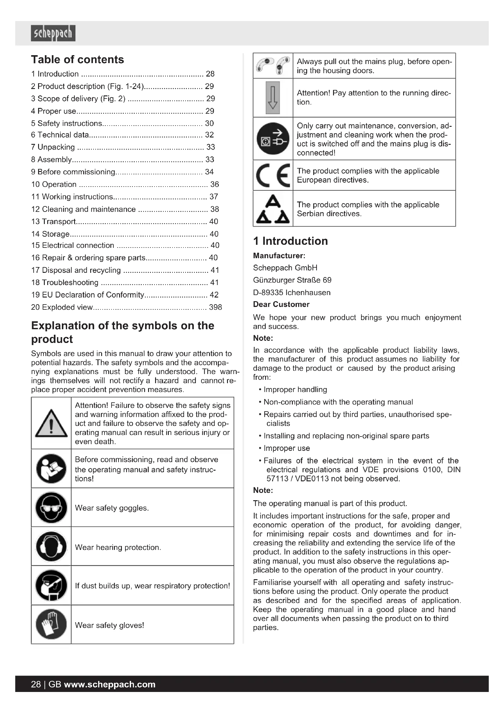
2 Product description (Fig. 1-24)
- On/off switch
1a. STOP switch
-
Clamping screw
-
Magnetic plate
-
Clamping nut
-
Band saw blade guard
-
Band saw blade
-
Transverse cutting gauge
10b. Clamping screw (parallel stop)
- Housing doors
11a. Safety switch
11b. Allen screw (housing door)
- Adjustment handle (top band wheel)
12a. Wing nut (top band wheel)
-
Push stick
-
Graduated scale (pivot range)
-
Scale pointer (swivelling range)
-
Engine
-
Suction port
-
Locking handle
-
knurled nut
-
Clamping plate
-
Main frame
-
End stop screw (saw table adjustment)
22a. Counternut (saw table adjustment)
-
Top band wheel
-
Running surfaces (band saw blade)
-
Bottom band wheel
-
Top saw band guide
-
Support bearing
27a. Rear upper support bearing
27b. Grub screw
27c. Upper lateral support bearing
27d. Grub screw
27e. Rear lower support bearing
27f. Grub screw
27g. Lower lateral support bearing
27h. Grub screw
- Top retainer
28a. Screw (top retainer)
- Belt
29a. Belt tensioning screw
-
Drive belt pulley
-
Band wheel pulley
-
Table inlay
32a. Philips screw (table inlay)
-
Band wheel circlip
-
Band wheel shaft
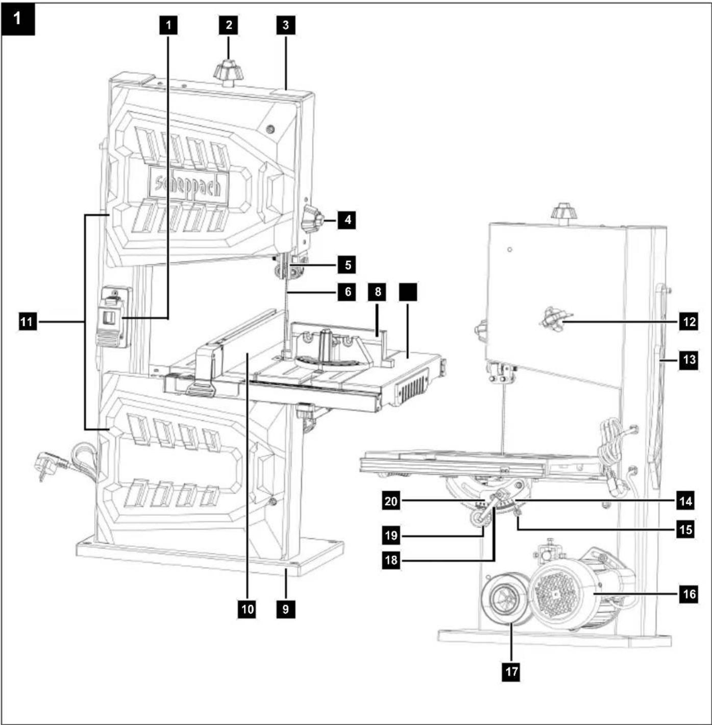
3 Scope of delivery (Fig. 2)
Item QuantityDesignation
-
1 x Saw table
-
1 x Band saw blade (pre-assembled)
-
1 x Parallel stop
-
1 x Push stick
-
1 x Locking handle
-
1 x Clamping plate
A. 1 x Open-ended spanner, size 8/10
B. 1 × Allen key, 3 mm
C. 1 x Allen key, 4 mm
D. 1 x Allen key, 5 mm
E. 1 x Allen key, 6 mm
F. 2 x Allen screws (M6x12 mm)
G. 2 x Washer (M6)
H. 2 x Snap ring (M6)
I. 1 x Allen screw (M6x25 mm)
J. 1 x Nut (M6)
K. 1 x Hexagon screw (M6x40 mm)
L. 1 x Wing nut (M6)
1 x Band saw
1 x Operating manual
4 Proper use
The band saw is used for the longitudinal and transverse cutting of timbers or wood-like workpieces. Round materials may only be cut using suitable holding devices.

WARNING
Do not use the product to cut materials other than those described in the operating manual.

WARNING
The supplied band saw blade is only intended for the sawing of wood! Do not use this blade for sawing firewood!
The product may only be used in the intended manner. Any use beyond this is improper. The user/operator, not the manufacturer, is responsible for damages or injuries of any type resulting from this.
Only suitable band saw blades may be used for the product.
An element of the intended use is also the observance of the safety instructions, as well as the assembly instructions and operating information in the operating manual.
Persons who operate and maintain the product must be familiar with the manual and must be informed about potential dangers.
The liability of the manufacturer and resulting damages are excluded in the event of modifications of the product.
Please note that our products were not designed with the intention of use for commercial or industrial purposes. We assume no guarantee if the product is used in commercial or industrial applications, or for equivalent work.
Explanation of the signal words in the operating manual

DANGER
Signal word to indicate an imminently hazardous situation which, if not avoided, will result in death or serious injury.

WARNING
Signal word to indicate a potentially hazardous situation which, if not avoided, could result in death or serious injury.

CAUTION
Signal word to indicate a potentially hazardous situation which, if not avoided, could result in minor or moderate injury.
ATTENTION
Signal word to indicate a potentially hazardous situation which, if not avoided, could result in product or property damage.
5 Safety instructions
General power tool safety warnings
Save all warnings and instructions for future reference.
The term "power tool" in the warnings refers to your mains-operated (corded) power tool or battery-operated (cordless) power tool.

WARNING
Read all safety warnings, instructions, illustrations and specifications provided with this power tool.
Failure to follow all instructions listed below may result in electric shock, fire and/or serious injury.
1) Work area safety
a) Keep your work area clean and well-lit. Cluttered or dark areas invite accidents.
b) Do not operate power tools in explosive atmospheres, such as in the presence of flammable liquids, gases or dust. Power tools create sparks which may ignite the dust or fumes.
c) Keep children and bystanders away while operating a power tool. Distractions can cause you to lose control.
2) Electrical safety
a) The connection plug of the electric tool must fit into the socket. Never modify the plug in any way. Do not use any adapter plugs with earthed (grounded) power tools. Unmodified plugs and matching outlets will reduce risk of electric shock.
b) Avoid body contact with earthed or grounded surfaces, such as pipes, radiators, ranges and refrigerators. There is an increased risk of electric shock if your body is earthed or grounded.
c) Do not expose power tools to rain or wet conditions. Water entering a power tool will increase the risk of electric shock.
d) Do not abuse the cord. Never use the cord for carrying, pulling or unplugging the power tool. Keep cord away from heat, oil, sharp edges or moving parts. Damaged or entangled cords increase the risk of electric shock.
e) When operating a power tool outdoors, use an extension cord suitable for outdoor use. Use of a cord suitable for outdoor use reduces the risk of electric shock.
f) If operating a power tool in a damp location is unavoidable, use a residual current device (RCD) protected supply. Use of an RCD reduces the risk of electric shock.
3) Personal safety
a) Stay alert, watch what you are doing and use common sense when operating a power tool. Do not use a power tool while you are tired or under the influence of drugs, alcohol or medication. A moment of inattention while operating power tools may result in serious personal injury.
b) Wear personal protective equipment and always safety goggles. Protective equipment such as a dust mask, non-skid safety shoes, safety helmet or hearing protection used for appropriate conditions will reduce personal injuries.
c) Prevent unintentional starting. Ensure the switch is in the off-position before connecting to power source and/or rechargeable battery, picking up or carrying the tool. Carrying power tools with your finger on the switch or energising power tools that have the switch on invites accidents.
d) Remove any adjusting tools or spanners/keys before turning the power tool on. A wrench or a key left attached to a rotating part of the power tool may result in personal injury.
e) Avoid abnormal postures. Keep proper footing and balance at all times. This enables better control of the power tool in unexpected situations.
f) Dress properly. Do not wear loose clothing or jewellery. Keep your hair and clothing away from moving parts. Loose clothes, jewellery or long hair can be caught in moving parts.
g) If devices are provided for the connection of dust extraction and collection facilities, ensure these are connected and properly used. Use of dust extraction can reduce dust-related hazards.
h) Do not let familiarity gained from frequent use of tools allow you to become complacent and ignore tool safety principles. A careless action can cause severe injury within a fraction of a second.
4) Power tool use and care
a) Do not force the power tool. Use the correct power tool for your application. The correct power tool will do the job better and safer at the rate for which it was designed.
b) Do not use the power tool if the switch does not turn it on and off. Any power tool that cannot be controlled with the switch is dangerous and must be repaired.
c) Disconnect the plug from the power source and/or remove the battery pack, if detachable, from the power tool before making any adjustments, changing accessories, or storing power tools. Such precautionary measures reduce the risk of starting the power tool accidentally.
d) Store idle power tools out of the reach of children and do not allow persons unfamiliar with the power tool or these instructions to operate the power tool. Power tools are dangerous in the hands of untrained users.
e) Maintain power tools and attachments. Check for misalignment or binding of moving parts, breakage of parts and any other condition that may affect the power tool's operation. If damaged, have the power tool repaired before use. Many accidents are caused by poorly maintained power tools.
f) Keep cutting tools sharp and clean. Properly maintained cutting tools with sharp cutting edges are less likely to bind and are easier to control.
g) Use electric tools, insertion tools, etc. according to these instructions. Take into account the working conditions and the work to be performed. Use of the power tool for operations different from those intended could result in a hazardous situation.
h) Keep handles and grasping surfaces dry, clean and free from oil and grease. Slippery handles and grasping surfaces do not allow for safe handling and control of the tool in unexpected situations.
5) Service
a) Only have your power tool repaired by qualified specialists and only with original spare parts. This will ensure that the safety of the power tool is maintained.
5.1 Safety instructions for band saws
a) Do not use damaged or deformed saw blades. Damaged or deformed saw blades could break and/or bend.
b) Do not use coolant fluids. The use of water or other coolants can cause electric shock.
c) Operate the band saw at the appropriate speed for the permissible applications and materials. Working at an improper speed for the material being cut can lead to saw blade breakage and bodily injury.
d) Do not operate the power tool with the access cover to the saw blade open. Contact with moving parts can cause bodily injury.
5.2 Additional safety instructions

WARNING
Tool attachments may be sharp and become hot during use. Always wear protective gloves when handling the tool attachments.
- When cutting round or irregular shaped wood, use a device to secure the workpiece and prevent it turning.
- When cutting boards on edge, use a device to prevent the workpiece kicking back.
- If devices are provided for the connection of dust extraction and collection facilities, ensure these are connected and properly used. Use of dust extraction can reduce dust-related hazards.
• The product may only be operated by people who are familiar with handling it.

WARNING
The supplied band saw blade is only intended for the sawing of wood! Do not use this blade for sawing firewood!
- Before commissioning, ensure that the mains voltage matches with the operating voltage on the type plate.
- Long supply cables, extensions, cable reels, etc. cause a drop in voltage and can impede motor start-up.
- Keep children and other people away while using the product. Distractions may cause you to lose control of the product.
- Observe the direction of rotation of the motor and saw band.
- Never operate the product with defective Protective devices or without safety devices.
- Do not process workpieces that are too small in order to keep them secure in your hands.

WARNING
Danger of injury!
If you remove blockages with your bare hands, you may injure yourself.
- Wear protective gloves.
-
Use suitable tools (e.g. a wooden stick).
-
Set the adjustable guards such that they are as close as possible to the workpiece.
- Protective covers must not be used for transport or improper operation of the product.

WARNING
Do not use damaged or deformed tool attachments.

WARNING
Make sure that the tool attachment is suitable for the material to be processed.

WARNING
With a damaged table inlay there is a risk of small parts jamming between table inlay and saw blade, blocking the saw blade.
Immediately replace damaged table inlays!

WARNING
There is a risk of accident! Always carry out cleaning work when the product is switched off. There is a danger of injury! Let the product cool down before cleaning. Elements of the engine are hot. There is a danger of injury and burning!
The product can start unexpectedly and cause injuries.
- Switch off the product before all cleaning work.
- Allow the engine to cool down.
ATTENTION
The teeth of the band saw blade must point downwards.
- Do not use the product if it is damaged. Never remove protective devices from the product. This can result in serious injuries.
- For mitre cuts with an inclined saw table, the parallel stop should be placed on the lower part of the saw table.
ATTENTION
Secure long workpieces against tipping at the end of the cutting process (e.g. with a roller stand or similar).
- Keep your hands at a safe distance from the band saw blade. Use a push stick for narrow cuts.
- Store the push stick on the holder provided for it on the product so that you can reach it from your normal working position and always have it to hand.
- Switch the product off if it is not in use.
- In the normal working position, the operator is in front of the product.
Residual risks
The product has been built according to state-of-the-art and the recognised technical safety rules. However, individual residual risks can arise during operation.
- Residual risks can be minimised if the "Safety Instructions" and the "Intended Use" together with the operating manual as a whole are observed.
- Use the product in the way that is recommended in this operating manual. This is how to ensure that your product provides optimum performance.
• Furthermore, despite all precautions having been met, some non-obvious residual risks may still remain. - Keep your hands away from the working area when the product is in operation.
- Damage to hearing if the stipulated hearing protection is not worn.
- Damage to the lungs if the stipulated respiratory protection is not worn.
- Risk of injury from tools thrown away due to improper holding or guiding.
• Health hazard due to electrical power, with the use of improper electrical connection cables. - Avoid accidental start-up of the product: when inserting the plug into the socket, do not press the on/off switch.
- Before performing setting or maintenance work, release the on/off switch and pull out the mains plug.
WARNING
This power tool generates an electromagnetic field during operation. This field can impair active or passive medical implants under certain circumstances. In order to prevent the risk of serious or deadly injuries, we recommend that persons with medical implants consult with their physician and the manufacturer of the medical implant prior to operating the power tool.
WARNING
In case of extended working periods, the operating personnel may suffer circulatory disturbances in their hands (vibration white finger) due to vibrations.
Raynaud's syndrome is a vascular disease that causes the small blood vessels on the fingers and toes to cramp in spasms. The affected areas are no longer supplied with sufficient blood and therefore appear extremely pale. The frequent use of vibrating products can cause nerve damage in people whose circulation is impaired (e.g. smokers, diabetics).
If you notice unusual adverse effects, stop working immediately and seek medical advice.
6 Technical data
| AC motor 230 - 240V~ 50 Hz | |
| Power consumption 370 Watt (S1*) | |
| 550 Watt (S2 20min**) | |
| Idle speed n0 | 1480 rpm |
| Band saw blade length 1790 mm | |
| Band saw blade width 6 mm | |
| Max. band saw blade width 13 mm | |
| Band saw blade speed 720/1000 m/min | |
| Cut height 130 mm | |
| Swing | 245 mm |
| Saw table size | 307 x 315 mm |
| Saw table size with extension | 315 x 520 mm |
| Inclinable saw table | 0° - 45° |
| Max. workpiece size | 580x400x130 mm |
| Cable length | 1800 mm |
| Weight | approx. 22 kg |
Subject to technical changes!
*Operating mode S1 (continuous operation)
The product can be operated continuously with the specified power.
**Operating mode S2 (short-term operation)
The product may only be operated at the specified power for a brief time (20 min.).
The workpiece must have a minimum height of 3 mm and a minimum width of 10 mm.
Noise data
WARNING
Noise can have serious effects on your health. If the machine noise exceeds 85 dB, please wear suitable hearing protection for you and persons in the vicinity.
The noise and vibration values have been determined in accordance with EN 62841.
| Sound pressure level L_pA | 73 dB |
| Uncertainty K_pA | 3 dB |
| Sound power level L_wA | 86 dB |
| Uncertainty K_wA | 3 dB |
The specified noise emission values have been measured in accordance with a standardised test procedure and can be used to compare one power tool with another.
The specified device emissions values can also be used for an initial estimation of the load.

WARNING
The noise emission values can vary from the specified values during the actual use of the power tool, depending on the type and the manner in which the electric tool is used, and in particular the type of workpiece being processed.
Try to keep the stress as low as possible. For example: Limit working time. In doing so, all parts of the operating cycle must be taken into account (such as times in which the power tool is switched off or times in which it is switched on, but is not running under a load).
7 Unpacking

WARNING
The product and the packaging material are not children's toys!
Do not let children play with plastic bags, films or small parts! There is a danger of choking or suffocating!
- Open the packaging and carefully remove the product.
- Remove the packaging material, as well as the packaging and transport safety devices (if present).
- Check whether the scope of delivery is complete.
- Check the product and accessory parts for transport damage. Immediately report any damage to the transport company that delivered the Product. Later claims will not be recognised.
- If possible, keep the packaging until the expiry of the warranty period.
- Familiarise yourself with the product by means of the operating manual before using for the first time.
- With accessories as well as wearing parts and replacement parts use only original parts. Spare parts can be obtained from your specialist dealer.
- When ordering please provide our article number as well as type and year of manufacture for the product.
8 Assembly
ATTENTION
Always make sure the product is fully assembled before commissioning!

WARNING
Pull out the mains plug before carrying out any setting, servicing or repair work!
Tool required:
- 1 x open-ended spanner, AF 8/10 mm* (A)
- 1 x Allen key 3 mm* (B)
- 1 x Allen key 4 mm* (C)
- 1 x Allen key 5 mm* (D)
- 1 x Allen key 6 mm* (E)
* = may not be included in the scope of delivery!
Note:
You can store the tool supplied on the magnetic strip on the product head.
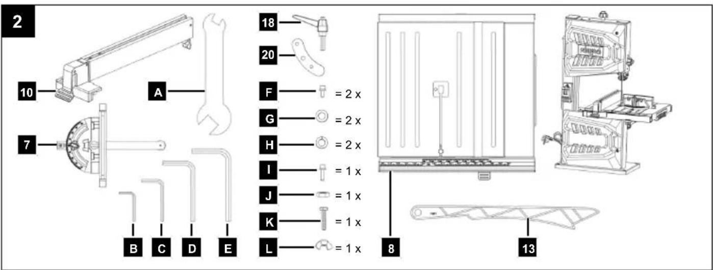
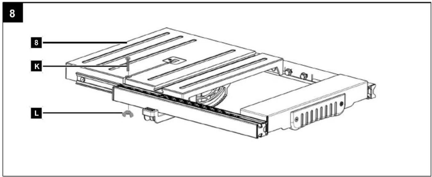
8.1 Assembling the saw table (8)
(Fig. 1, 3, 4, 5, 6, 8)
Note:
The saw table must be adjusted before initial commissioning and after each saw table disassembly.
- Extend the saw table (8) as described under 10.1.
- Guide the saw table (8) over the band saw blade (6).
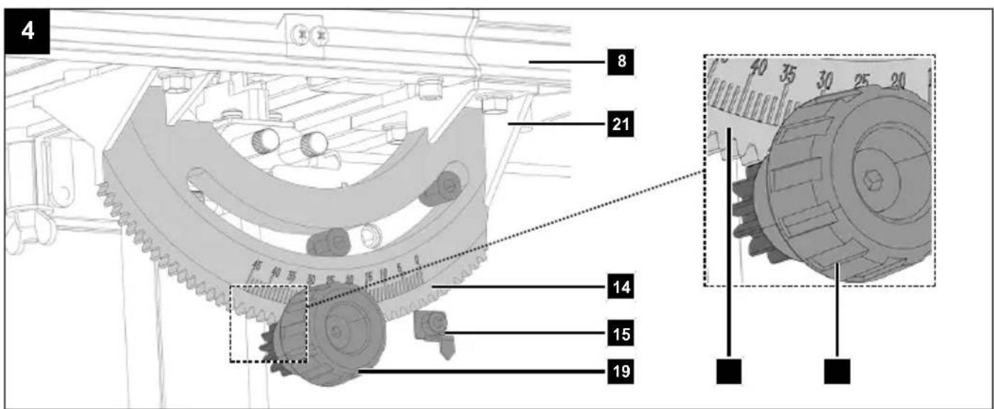
- The scale pointer (15) must be released and must not point upwards. Use a 4 mm Allen key.
- Place the recess of the degree scale (14) in the two guides on the frame (21). Ensure that the toothing of the saw table (8) engages with the toothing of the knurled nut (19) on the frame (21).
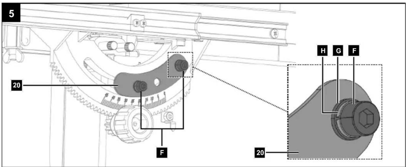
- Attach the saw table (8) with the clamping plate (20), the two Allen screws (F), the washers (G) and the snap ring washers (H) to the respective mounting holes on the frame (21). Use a 5 mm Allen key.
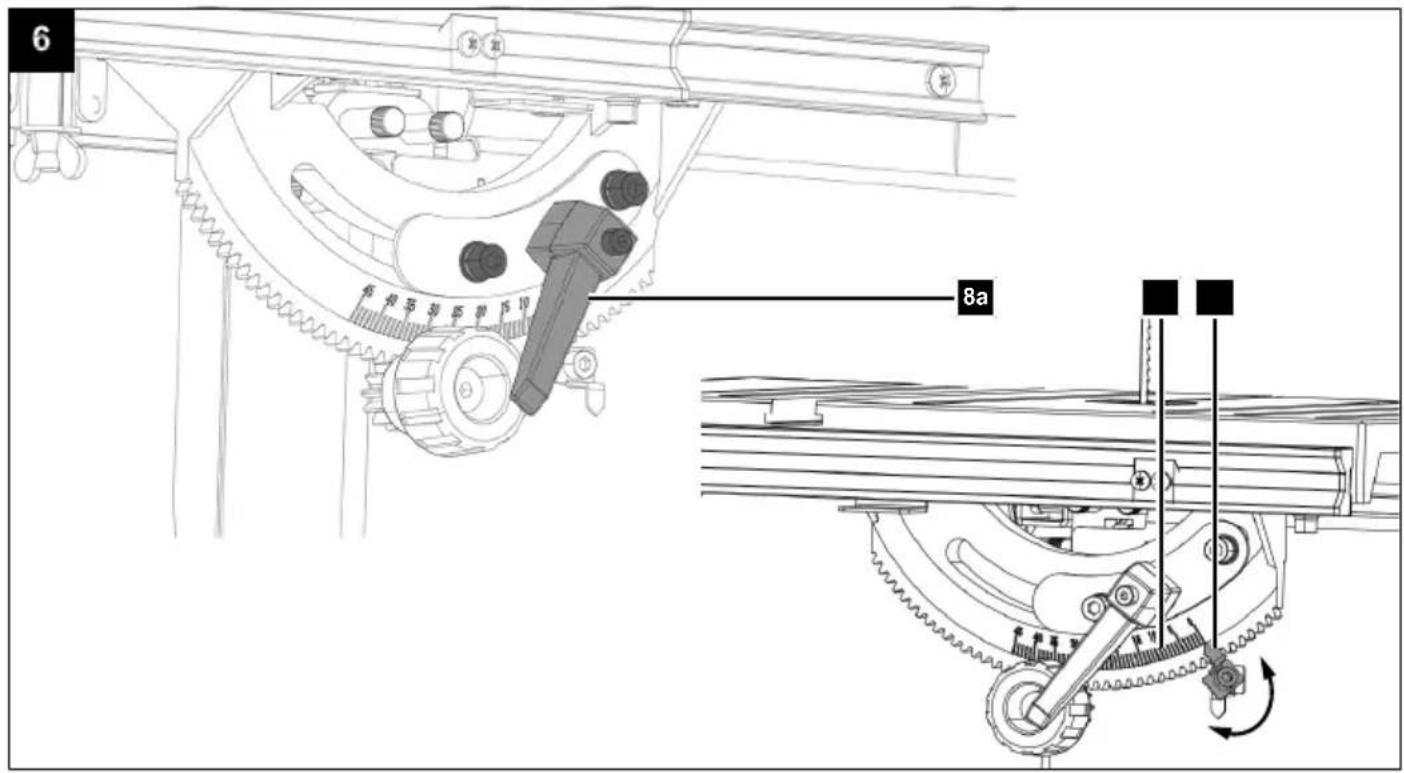
- Fit the clamping lever (8a) in the centre mounting hole. Do not tighten the clamping lever (8a) yet.
- Set the scale pointer (15) so that it points to the degree scale. Use a 4 mm Allen key.
- Adjust the saw table (8) to 0° as described under 8.2.
- Tighten the clamping lever (8a) to fix the saw table (8) in place. Tighten the two Allen screws (F). Use a 5 mm Allen key.
- If necessary, readjust the scale pointer (15) and set it to 0^ .
- To stiffen the saw table (8), fit the hexagon screw (K) with the wing nut (L).
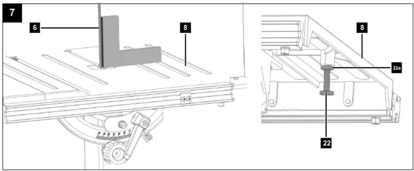
8.2 Adjusting the saw table (8) to 90° (Fig. 7)
- Adjust the saw table (8) horizontal to 0°.
- Check the end stop screw (22) and the counternut (22a) for firm seating and tighten if necessary. Use an open-ended spanner AF 8/10 (A).
- If the saw table (8) is not adjusted at a right-angle to the band saw blade (6), the end stop screw (22) must be readjusted.
- Loosen the end stop screw (22) and the counternut (22a). Use an open-ended spanner AF 8/10 (A).
-
Turn the end stop screw (22) clockwise to lower the end stop point or anti-clockwise to increase it.
-
Align the saw table (8) at right angles to the band saw blade (6) using an angle bracket*, bring the end stop screw (22) into the desired position and retighten the lock nut (22a). Use an open-ended spanner AF 8/10 (A).
* = may not be included in the scope of delivery!
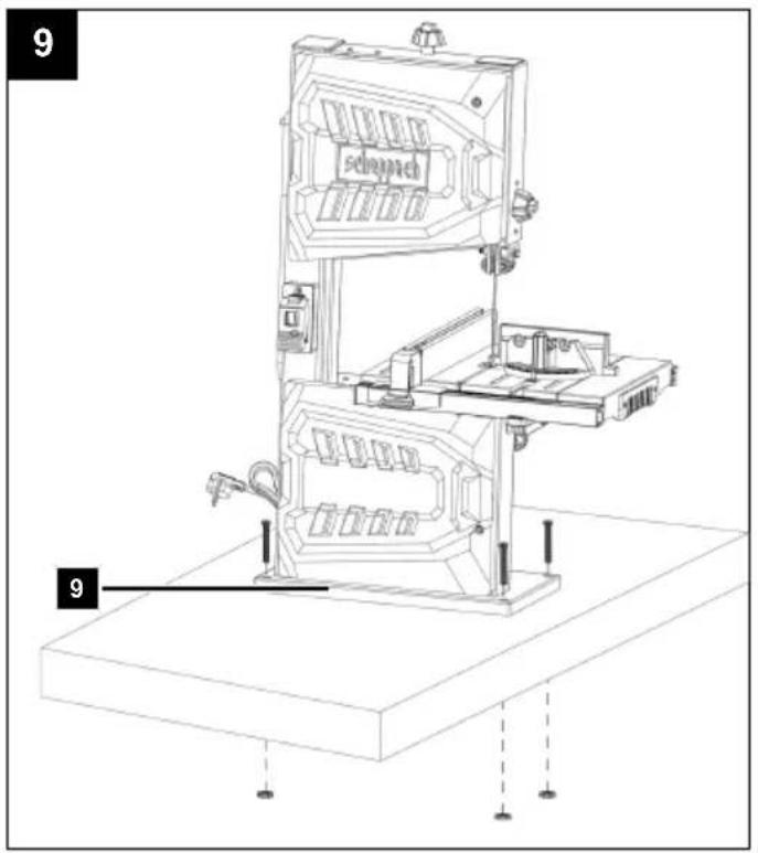
8.3 Use as a stationary machine (Fig. 1)
The product must be mounted on a workbench for continuous use.
-
The product must be securely installed, i.e. bolted down on a workbench or fixed machine stand.
• There are fixing holes in the foot (9) for this purpose. -
Mark the drill holes.
-
Place the product as it will be installed later.
– Mark the positions of the holes to be drilled on the workbench.
These are given by the holes in the foot (9).
We recommend installing close to the edge.
- Drill the holes (at least 8 mm diameter) through the workbench.
- Place the product over the drilled holes congruent with the holes in the foot (9) and insert suitable screws* through the holes from above and tighten them.
* = may not be included in the scope of delivery!
8.4 Extraction port set (17) (Fig. 1)
The product is equipped with an extraction port.
The suction nozzle (17) has three different diameters.
Connect a dust extractor when processing dusty materials.
ATTENTION
The dust extraction system must be suitable for the material to be processed.
Use a special extraction device to extract particularly harmful or carcinogenic dusts.
- Connect the hose of a suitable dust extraction system* (e.g. industrial hoover) directly to the desired extraction port set (17).
* = may not be included in the scope of delivery!
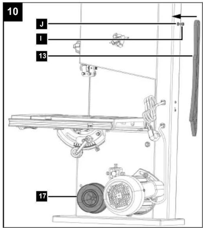
8.5 Push stick retainer (Fig. 10)
- Fit the screw (I) with the nut (J) for the push stick retainer to the frame (21). Use a 5 mm Allen key (D) and an 8/10 mm open-end spanner (A).
- Attach the push stick (13) to the screw (I).
Note:
If unused, the push stick must always be stowed in the push stick retainer.
9 Before commissioning
Tool required:
- 1 x open-ended spanner, AF 8/10 mm* (A)
-
1 x Allen key 3 mm* (B)
-
1 x Allen key 4 mm* (C)
- 1 x Allen key 5 mm* (D)
• 1 x Allen key 6 mm* (E)
* = may not be included in the scope of delivery!
9.1 Which band saw blade to use
Check that the tool attachment is fitted securely.
Tool attachments that are not fitted correctly or securely may come loose during operation and injure you.
The band saw blade included in the scope of delivery is intended for universal use. The following criteria should be considered when selecting the band saw blade:
- It is possible to cut tighter radii with a narrow band saw blade than with a wide band saw blade.
- Use wide band saw blades to perform straight cuts. This is important in particular when cutting wood. The band saw blade has a tendency to follow the wood grain and therefore deviates easily from the desired position.
- Fine-toothed band saw blades cut more smoothly, but also more slowly than coarse band saw blades.
- Only use undamaged band saw blades that are in perfect condition. Band saw blades that are bent, blunt or damaged in any other way can break.
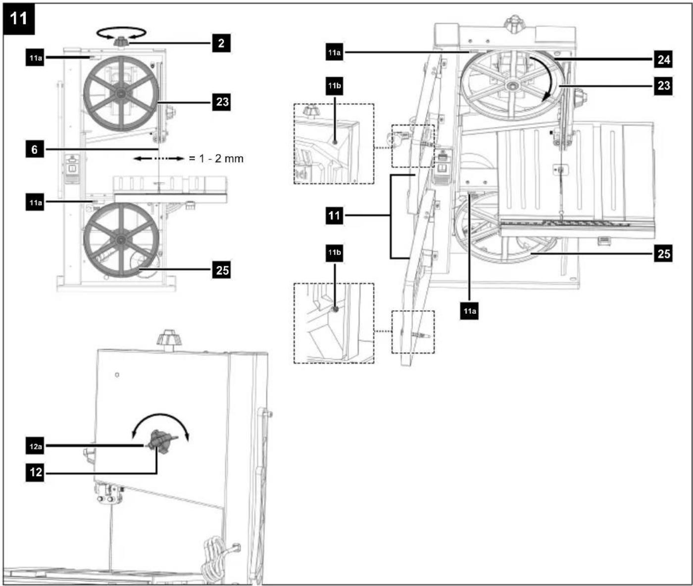
9.2 Tensioning the band saw blade (6) (Fig. 11)
ATTENTION
If the band saw is at a standstill for an extended period, the band saw blade tension must be relieved, i.e. before switching the band saw on it is necessary to check the band saw blade tension.
- To tension the band saw blade (6), turn the clamping screw (2) clockwise.
Notes:
- The correct tension of the band saw blade can be determined by pressing the finger laterally against the band saw blade, roughly centrally between the two band wheels. The band saw blade should only depress slightly (approx. 1-2 mm) here.
• The sufficiently tensioned band saw blade makes a metallic sound when tapped. - Relieve the band saw blade tension if it is not in use for an extended time, so that it does not become over-stretched.
ATTENTION
With high tension, the band saw blade may break.
ATTENTION
Danger of injury!
If the tension is too low, the driven band wheel may spin, resulting in the band saw blade coming to a standstill.
- To relieve the band saw blade (6), turn the clamping screw (2) anti-clockwise.
9.3 Adjust the band saw blade (6) (Fig. 11)
ATTENTION
Before it is possible to implement the band saw blade setting, the band saw blade must be tensioned correctly.
- Open the housing doors (11) by loosening the Allen screws (11b). Use a 5 mm Allen key (D).
-
Turn the top band wheel (23) clockwise slowly. The band saw blade (6) must run in the centre on the running surfaces (24) of the top band wheel (23). If this is not the case, correct the angle of the top band wheel (23).
-
To do this, open the wing nuts (12a).
-
If the band saw blade (6) runs more towards the rear edge of the band wheel (23), then the adjustment handle (12) must be rotated anti-clockwise.
-
If the band saw blade (6) runs more towards the front edge of the band wheel (23), then the adjustment handle (12) must be rotated clockwise.
-
After setting the top band wheel (23), check the position of the band saw blade (6) on the bottom band wheel (25).
-
Turn the bottom band wheel (25) slowly by hand to check the position of the band saw blade (6).
-
The band saw blade (6) should be positioned in the centre on the running surfaces (24) of the bottom band wheel (25). If this is not the case, the angle of the top band wheel (23) must be adjusted again.
-
To ensure that the adjustment of the top band wheel (23) influences the position of the band saw blade (6) on the bottom band wheel (25), turn the bottom band wheel (25) several times.
-
Retighten the wing nut (12a).
-
Once the adjustment is complete, close the housing doors (11) again and secure them with the Allen screws (11b). Use a 5 mm Allen key (D).
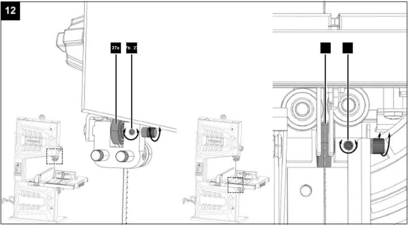
9.4 Adjusting the band saw blade guide (Fig. 1, 11, 12, 13, 14, 15)
- The support bearings (27) must be readjusted before initial start-up and after every band saw blade change.
-
The rear and lateral band saw blade guide is adjusted using eccentric support bearings (27a, 27c, 27e, 27g). These eccentric support bearings (27a, 27c, 27e, 27g) enable precise fine adjustment of the position and alignment of the band saw blade (6) to improve the accuracy and performance of the product.
-
Open the housing doors (11) by loosening the Allen screws (11b). Use a 5 mm Allen key (D).
9.4.1 Rear upper support bearing (27a) (Fig. 12)
The rear upper support bearing (27a) absorbs the feed pressure of the workpiece.
-
Loosen the grub screw (27b) of the upper support bearing (27a). Use the 3 mm Allen key (B).
-
Turn the rear upper support bearing (27a) until it just no longer touches the band saw blade (6) (max. distance 0.5 mm). Ensure that the rear upper support bearing (27a) is centred in relation to the band saw blade (6).
- Retighten the grub screw (27b) of the rear upper support bearing (27a). Use the 3 mm Allen key (B).
9.4.2 Rear lower support bearing (27e) (Fig. 12)
The rear lower support bearing (27e) absorbs the feed pressure of the workpiece.
- Loosen the grub screw (27f) of the rear lower support bearing (27e). Use the 3 mm Allen key (B).
- Turn the rear lower support bearing (E) until it just no longer touches the band saw blade (6) (max. distance 0.5 mm).
Ensure that the rear lower support bearing (27e) is centred in relation to the band saw blade (6). - Retighten the grub screw (27f) of the rear lower support bearing (27e). Use the 3 mm Allen key (B).
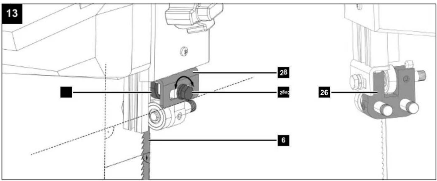
9.4.3 Top retainer (28) (Fig. 13)
Ensure that the top retainer (28) is in a horizontal position and the top support bearing (27) is centred in relation to the band saw blade (6).
- Loosen the screw (28a) of the top retainer (28) and align the top retainer (28) with the band saw blade (6). Use a Phillips screwdriver or the open-end spanner WAF 8/10 (A).
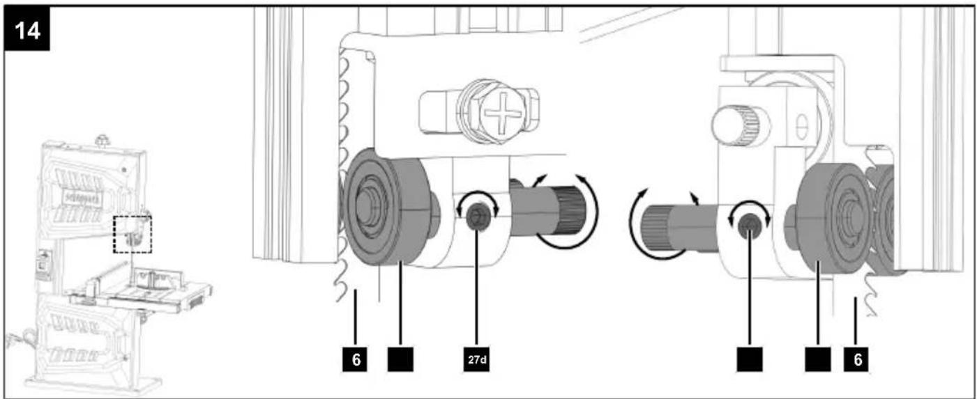
9.4.4 Upper lateral support bearing (27c) (Fig. 14)
The lateral support bearings (27c, 27g) serve to stabilise and align the band saw blade (6) during operation. They help to ensure that the band saw blade (6) remains in the correct position and track during the cutting process.
- Loosen the grub screws (27d) of the upper lateral support bearings (27c).
Use the 3 mm Allen key (B). - Turn the upper lateral support bearings (27c) until they just no longer touch the band saw blade (6) (max. distance 0.5 mm).
Ensure that the upper lateral support bearings (27c) are centred in relation to the band saw blade (6) and parallel to each other. - Retighten the grub screws (27d) of the upper lateral support bearings (27c).
Use the 3 mm Allen key (B).
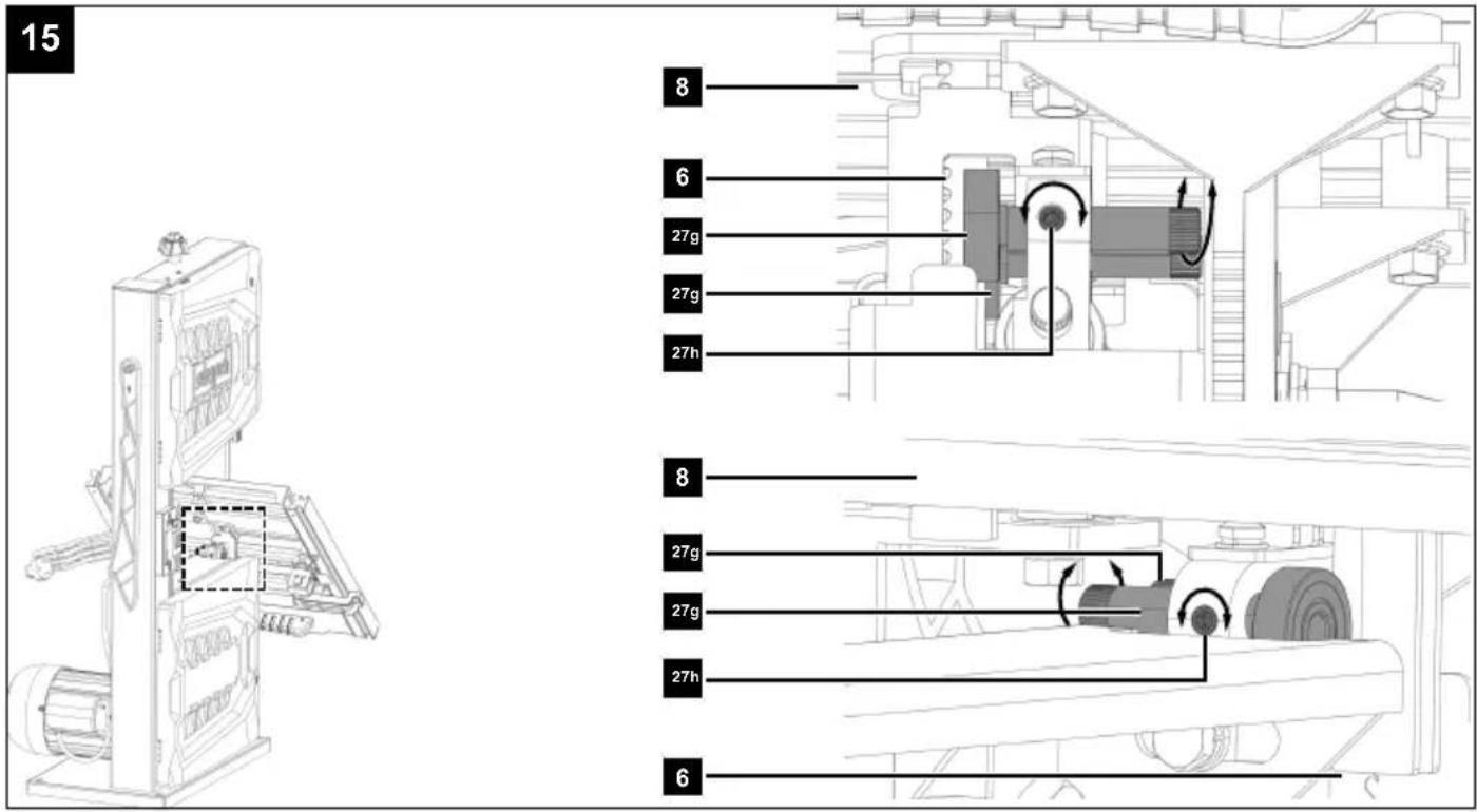
9.4.5 Lower lateral support bearings (27g) (Fig. 15)
To adjust the lower lateral support bearings (27g), it may be necessary to tilt the saw table (8) to 45°. (See 10.4)
- Loosen the grub screws (27h) of the lower lateral support bearings (27g).
Use the 3 mm Allen key (B). -
Turn the lower lateral support bearings (27g) until they just no longer touch the band saw blade (6) (max. distance 0.5 mm).
Ensure that the lower lateral support bearings (27g) are centred in relation to the band saw blade (6) and parallel to each other. -
Retighten the grub screws (27h) of the lateral lower support bearings (27g). Use the 3 mm Allen key (B).
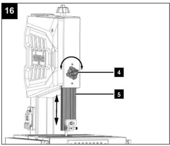
9.5 Adjust the band saw blade guard (5) (Fig. 16)
Note:
Check the setting before every cutting process and adjust if necessary.
- Loosen the clamping nut (4).
- Lower the band saw blade guard (5) by hand as close as possible (distance approx. 2-3 mm) to the workpiece to be processed.
- Retighten the clamping nut (4).
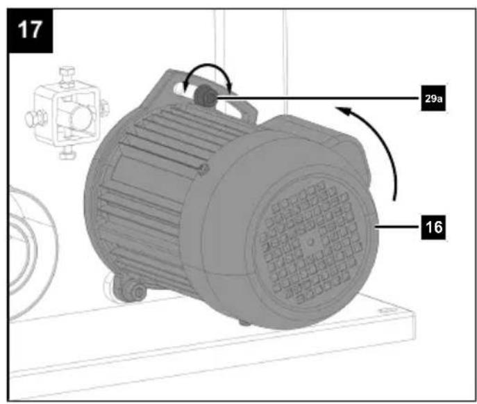
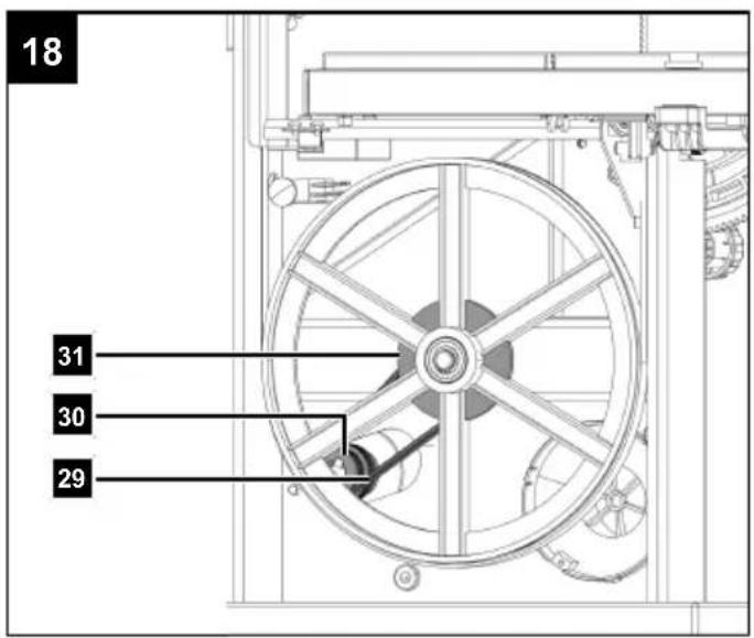
9.6 Setting the belt speed (Fig. 11, 17, 18)
- Open the lower housing door (11) by loosening the Allen screws (11b). Use a 5 mm Allen key (D).
- Loosen the belt tensioning screw (29a) on the motor (16) and press the motor (16) slightly upwards to slacken the belt (29). Use a 6 mm Allen key (E).
- Place the belt (29) on the desired drive belt pulley (30) and on the parallel running band wheel pulley (31) (S1 or S2). Ensure that the notches interlock and that the belt (29) is centred on the drive belt pulley (30) and the band wheel pulley (31).
- Press the motor (16) slightly backwards and tighten the belt tensioning screw (29a) on the motor (16) again to tension the belt (29). Use a 6 mm Allen key (E).
- Close the lower housing door (11) again and secure it with the Allen screw (11b). Use a 5 mm Allen key (D).
Speed ranges
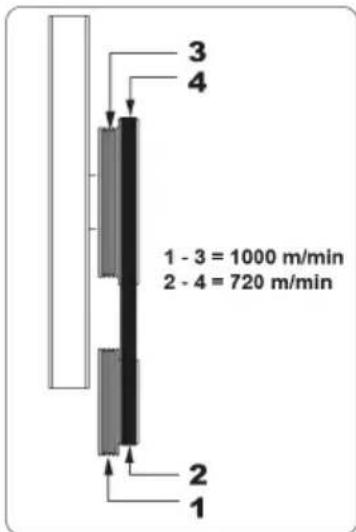
| 2-4 | 720 rpm Hardwood, hardwood-like materials, fine cuts |
| 1-3 | 1000 rpm Softwood, soft materials, medium and coarse cuts |
10 Operation
The band saw is a stationary saw with a driven band saw blade that is closed to form a ring. The band saw enables precise cuts to be made in wood and similar materials. Please refer to the following descriptions for the function of the controls.
ATTENTION
Always make sure the product is fully assembled before commissioning!
Note:
The product is equipped with a safety switch. This means that the product cannot be switched on if the doors are open or have not been closed properly.
Make sure that both safety switches (11a) engage properly on the housing doors (11).

WARNING
Danger of injury!
The on/off switch and the safety switch must not be locked!
- Do not work with the product if the switches are damaged.
- Make sure the product is in working order before each use.

WARNING
Always make sure that the tool attachment is fitted correctly!

WARNING
Make sure that the tool attachment is suitable for the material to be processed.
Note:
The product must be mounted on a workbench for continuous use.
- Let the tool attachment reach full speed before processing the workpiece.
- Select a tool attachment that corresponds to the material to be processed.
• The saw table must be mounted correctly. - Place the product in a stable location.
- Prior to commissioning, all covers and safety devices must be mounted correctly. Damaged or illegible stickers must be replaced.
- Check whether the moving parts function faultlessly and do not jam or whether parts are damaged. All parts must be correctly mounted and all conditions must be fulfilled to ensure fault-free operation of the power tool.
• In case of previously machined wood, be aware of any foreign bodies, such as nails or screws, etc. - Follow the running direction of the tool attachment.
10.1 Extending the saw table (8) (Fig. 3)
- Open the clamping lever (8a).
- Pull the saw table (8) out to the desired position.
- Lock the clamping lever (8a) again.
The clamping lever (8a) is closed when it is pointing downwards.
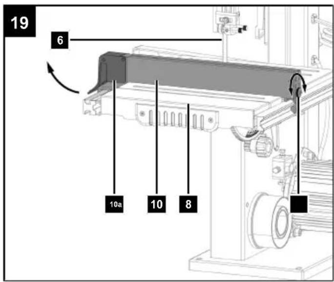
10.2 Parallel stop (10) (Fig. 19)
Note:
The parallel stop (10) can be fitted to the right of the band saw blade (6).
- Loosen the clamping bar (10a) of the parallel stop (10).
- First place the parallel stop (10) on the rear of the saw table (8) and then push the parallel stop (10) down.
-
Move the parallel stop (10) and adjust it to the desired dimension.
-
Push the clamping bar (10a) down to fix the parallel stop (10) in place. To increase the clamping force of the clamping bar (10a), loosen the clamping bar (10a), turn the clamping screw (10b) clockwise and press the clamping bar (10a) down again to test the clamping force. Repeat the process until the clamping force of the clamping bar (10a) is sufficient.
-
Make sure that the parallel stop (10) always runs parallel to the band saw blade (6).
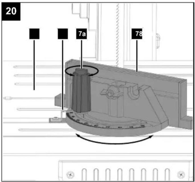
10.3 Mitre gauge (7) (Fig. 20)
- Insert the mitre gauge (7) into the groove of the saw table (8).
- Loosen the knurled nut (7a).
-
Turn the mitre gauge (7) until the desired angle has been set. The scale pointer (7b) on the mitre gauge (7) shows the set angle.
-
Retighten the knurled nut (7a).
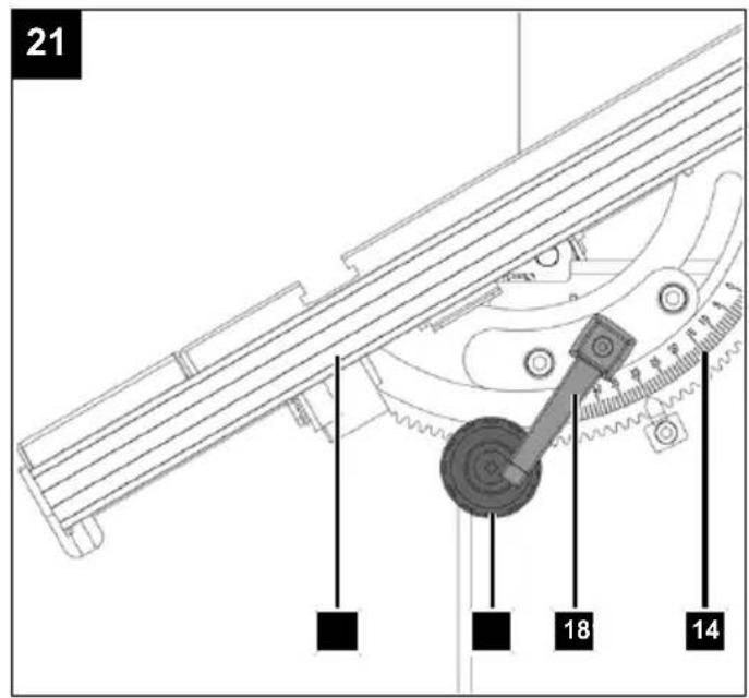
10.4 Angled cuts (Fig. 21)
In order to execute angled cuts parallel to the band saw blade (6), it is possible to tilt the saw table (8) from 0^ to 45^ .
- Adjust the saw table (6) as described under 8.2.
- Loosen the locking handle (18).
- The knurled nut (19) can be used to set the desired angle on the degree scale (14).
- Tighten the locking handle (18).
ATTENTION
With a tilted saw table, the parallel stop must always be fitted to the right of the band saw blade. This prevents the workpiece from slipping.
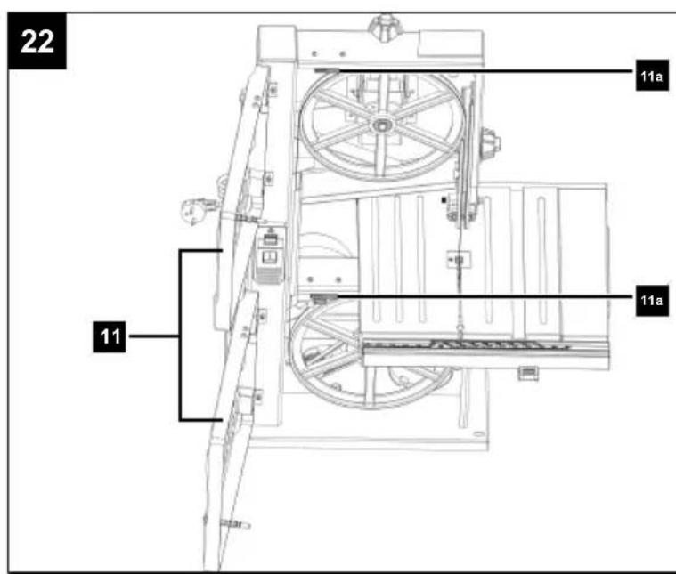
10.5 Switching the product on/off (fig. 1, 22)
Make sure that both safety switches (11a) engage properly on the housing doors (11).
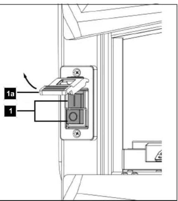
Switching on
- Insert the mains plug into a properly fused mains socket.
- Push the ON/OFF switch (1), which is marked "I", to switch the product on.
Switching off
- Press the STOP switch (1a) or lift the cover cap and press the "0" button on the on/off switch (1).
- Pull the mains plug out of the socket when the product is not in use.
11 Working instructions
The following safe working methods are considered to contribute to safety but may not be appropriate, fully or extensively applicable for every use. They cannot cover all possible hazardous conditions and must be interpreted carefully.
- Risk to health from wood dust or wood chippings. It is essential that personal protective equipment, such as eye protection, is worn. Use a chip extraction system!
- If the product is not in operation, e.g. work is complete, you should slacken the band saw blade. Attach a corresponding note to the product for the next user about the tensioning of the band saw blade.
- Store unused band saw blades together and safely in a dry place. Check for faults, such as teeth or cracks, before use. Do not use defective band saw blades!
WARNING
Tool attachments may be sharp and become hot during use. Always wear protective gloves when handling the tool attachments.
- Check the covers and protective devices for damage and correct seating. Replace them if necessary.
- Wear hearing protection and safety goggles during the entire operating period.
- Dress properly. Do not wear loose clothing or jewellery. Keep your hair and clothing away from moving parts. Loose clothes, jewellery or long hair can be caught in moving parts.
• Always position the band saw blade guide as close as possible to the workpiece when working. - Only work in daylight or with good, artificial lighting.
• Always use the parallel stop for straight cuts in order to prevent the workpiece from tilting or slipping. - Keep your hands at a safe distance from the band saw blade. Use a push stick for narrow cuts.
- For angled cuts, move the saw table into the appropriate position and guide the workpiece on the parallel stop.
-
To cut dovetail-shaped tines, pins or wedges, put the saw table into the corresponding position on the angle scale.
-
For curved and irregular cuts, you should guide the workpiece using both hands, push your closed fingers evenly. Hold the workpiece with your hands in a safe area.
- For repeated cutting of curve and irregular cuts, it is recommended to use an auxiliary template.
- When cutting round or irregular shaped wood, use a device to secure the workpiece and prevent it turning.
Note:
Before the first work and after each tool attachment change, carry out a test run without load. Switch off the product immediately if the tool attachment runs out of round, there is considerable vibration or abnormal noises are heard.
• Always position the band saw blade guide as close as possible to the workpiece when working.
- The workpiece must always be guided with both hands and kept flat against the saw table. This prevents the band saw blade from jamming.
- It is recommended to perform a cut in a single working step instead of dividing it into several sections, which may require the workpiece to be pulled back. However if pulling the workpiece back is unavoidable, the band saw should be switched off beforehand. The workpiece should only be pulled back once the band saw blade has come to a complete standstill.
- When sawing, the workpiece must always be guided by its longest side.
11.1 Performing longitudinal cuts (Fig. 1, 16)
Sawing along the wood fibre is referred to as a longitudinal cut. You can cut freehand along a marked out line or along the parallel stop to achieve a better result.
For right-angled cuts (saw table is at a right-angle to the band), the parallel stop is positioned to the left of the band saw blade so that the workpiece can be guided safely along the stop with the right hand.
ATTENTION
Secure long workpieces against tipping at the end of the cutting process (e.g. with a roller stand or similar).
- Set the parallel stop (10) as described under 10.2.
- Lower the band saw blade guard (5) onto the workpiece (see 9.5).
- Switch the saw on as described under 10.5.
- Place your hands flat on the workpiece with your fingers closed and slide it along the parallel stop (10) into the band saw blade (6).
- Always slide the workpiece at a steady rate long the parallel stop up to the end using a push stick (13).
11.2 Carrying out cross cuts (Fig. 20)
Cross cut refers to sawing at a right-angle to the fibre of the wood. Even this type of cutting can be performed free-hand, but it is recommended to use a mitre gauge for safety and accuracy. The mitre gauge can be adjusted for mitre cuts up to 45°. In combination with an inclined saw table, double mitre cuts can also be made.
- Use the mitre gauge (7) as described under 10.3.
- Hold the workpiece firmly against the stop of the mitre gauge (7) and flat on the saw table (8).
WARNING
Pay attention to your fingers, especially towards the end of the cut and maintain your distance from the tool attachment.
11.3 Performing angled cuts (Fig. 21)
For mitre cuts with an angled saw table, the parallel stop must be positioned on the downward facing side to the right of the band saw blade (if the workpiece width allows this), in order to secure the workpiece against slipping.
- Adjust the saw table (8) to the desired angle (see 10.4).
- Perform the cut as described under 11.1).
11.4 Freehand cuts (Fig. 1, 16)
One of the most important features of a band saw is the ease with which it can cut curves and radii.
- Lower the band saw blade guard (5) onto the workpiece (see 9.5).
- Switch the saw on as described under 10.5.
- Press the workpiece firmly onto the saw table (8) and push it slowly into the saw blade (6). In many cases, it is helpful to roughly saw out curves and corners approximately 6 mm away from the line.
- If it is necessary to saw curves that are too tight for the band saw blade used, auxiliary cuts must be sawn up to the front face of the curve. The final radius can be subsequently sawn out.
12 Cleaning and maintenance
WARNING
Pull out the mains plug before carrying out any setting, servicing or repair work!
12.1 Cleaning
WARNING
There is a risk of accident! Always carry out cleaning work when the product is switched off. There is a danger of injury! Let the product cool down before cleaning. Elements of the engine are hot. There is a danger of injury and burning!
The product can start unexpectedly and cause injuries.
- Switch off the product before all cleaning work.
- Allow the engine to cool down.
- Keep protective devices, air vents and the motor housing as free of dust and dirt as possible. Rub the product clean with a clean cloth* or blow it off with compressed air* at low pressure. We recommend that you clean the product directly after every use.
- Do not clean the tool attachment while it is still in operation.
- Never clean the band saw blade or the band saw blade guide with a hand-held brush or scraper if the band saw blade is running. Resinous band saw blades jeopardise work safety and must be cleaned regularly.
- Keep handles and grasping surfaces dry, clean and free from oil and grease. Slippery handles and grasping surfaces do not allow for safe handling and control of the tool in unexpected situations.
• We recommend that you clean the product directly after every use.
- Clean the product at regular intervals using a damp cloth* and a little soft soap. Do not use any cleaning products or solvents; they could attack the plastic parts of the product. Make sure that no water can penetrate the product interior.
12.2 Maintenance

WARNING
Have maintenance and repair tasks that are not described in this operating manual, carried out by a specialist workshop. Use only original spare parts.
There is a risk of accident! Always carry out maintenance and cleaning work with the motor switched off and the mains plug disconnected. There is a danger of injury! Let the Product cool down before all maintenance and cleaning tasks. Elements of the engine are hot. There is a danger of injury and burning!
The product can start unexpectedly and cause injuries.
- Switch off the product before all cleaning and maintenance work.
- Allow the product to cool down.
- Disconnect the mains plug!
Tool required:
- Allen key, 5 mm* (B)
- Allen key, 6 mm* (C)
- Circlip pliers*
• Phillips screwdriver*
* = may not be included in the scope of delivery!
12.2.1 Replacing the band saw blade (6) (Fig. 1, 3, 11, 13, 16)
-
Set the band saw blade guard (5) to about half height.
-
Open the housing doors (11) by loosening the Allen screws (11b).
Use a 5 mm Allen key (D).
-
Pull out the saw table (8) as described under 10.1 and remove the hexagon screw (K) and the wing nut (L).
-
To relieve the band saw blade (6), turn the clamping screw (2) anti-clockwise.
-
Remove the band saw blade (6) of two band wheels (23, 25) and remove the band saw blade (6) from the slot in the saw table (8).
-
Thread the new band saw blade (6) through the slot in the saw table (8) and place it in the centre of the running surface (24) of both band wheels (23, 25). The teeth of the band saw blade (6) must point downwards in the direction of the saw table (8).
-
Tension and adjust the band saw blade (6) (see 9.3, 9.2).
-
Once the adjustment is complete, close the housing doors (11) again and secure the Allen screws (11b). Use a 5 mm Allen key (D).
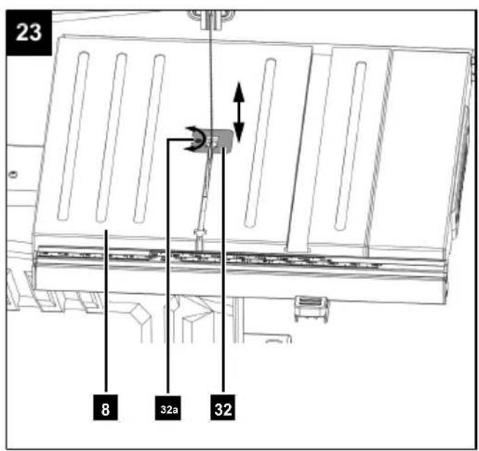
12.2.2 Replacing the table inlay (32) (Fig. 23)
Notes:
- Wear protective gloves.
- In the event of wear or damage the table inlay (32) must be replaced; otherwise there is an increased risk of injury.
-
Move the saw table (8) to the 0^ position as described under 8.2.
-
Remove the Phillips screw (32a) from the worn table inlay (32) and push the table insert out of the saw table (8) from bottom to top. Use a Phillips screwdriver*.
-
Installation of the new table inlay (32) takes place in reverse order.
* = may not be included in the scope of delivery!
12.2.3 Tensioning the belt (29) (Fig. 11, 17, 18)
-
Open the lower housing door (11) by loosening the Allen screws (11b). Use a 5 mm Allen key (D).
-
Loosen the belt tensioning screw (29a) on the motor (16). Use a 6 mm Allen key (E).
-
Push the motor (16) slightly backwards and retighten the belt tensioning screw (29a) on the motor (16) to tension the belt (29). Use a 6 mm Allen screw (E). Ensure that the notches interlock and that the belt (29) is centred on the drive belt pulley (30) and the band wheel pulley (31).
-
Close the lower housing door (11) again and secure it with the Allen screw (11b). Use a 5 mm Allen key (D).
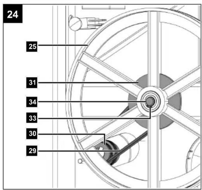
12.2.4 Replacing the belt (29) (Fig. 17, 24)
- Wear protective gloves.
-
Remove the band saw blade (6) as described under 12.2.1.
-
Loosen the belt tensioning screw (29a) and press the motor (16) slightly upwards to slacken the belt (29) and tighten the belt tensioning screw (29a) slightly. Use a 6 mm Allen key (E).
-
Dismantle the band wheel circlip (33). Use circlip pliers*.
-
Remove the lower band wheel (25) from the band wheel shaft (34) and remove the worn belt (29) from the band wheel pulley (31) and the drive belt pulley (30).
-
Place the new belt (29) over the drive belt pulley (30).
-
Attach the lower band wheel (25) to the band wheel shaft (34) and place the belt (29) over the band wheel pulley (31).
-
Place the belt (29) on the desired drive belt pulley (30) and on the parallel running band wheel pulley (31) (S1 or S2).
Ensure that the notches interlock and that the belt (29) is centred on the drive belt pulley (30) and the band wheel pulley (31).
- Press the motor (16) slightly backwards and tighten the belt tensioning screw (29a) on the motor (16) again to tension the belt (29).
Use a 6 mm Allen key (E).
- Fit the band saw blade (6) as described under 12.2.1.
* = may not be included in the scope of delivery!
13 Transport
- The product may only be lifted and transported on the frame or the foot. Never lift by the guards, adjustment handles or saw table for transport.
- To transport the product, disconnect the it from the power supply and set it up in the new position you want to use it in.
- The band saw blade guard must be in the lower position during transport of the band saw.
- The product must be secured against tipping and slipping during transport in vehicles in order to prevent damage and injuries.
- Never use guards for lifting or transport.
14 Storage
Store the product and its accessories in a dark, dry and frost-free place that is inaccessible to children.
The optimum storage temperature is between 5^ C and 30^ C.
Store the product in its original packaging.
Cover the product to protect it from dust or moisture.
Store the operating manual with the product.
15 Electrical connection
The electrical motor installed is connected and ready for operation. The connection complies with the applicable VDE and DIN provisions. The customer's mains connection as well as the extension cable used must also comply with these regulations.
15.1 Important information
In the event of overloading, the motor will switch itself off. After a cool-down period (time varies) the motor can be switched back on again.
15.2 Damaged electrical connection cables
The insulation on electrical connection cables is often damaged.
This may have the following causes:
- Pressure points, where connection cables are passed through windows or doors,
-
Kinks where the connection cable has been improperly fastened or routed,
-
Places where the connection cables have been cut due to being driven over,
• Insulation damage due to being ripped out of the wall socket, - Cracks due to the insulation ageing.
Such damaged electrical connection cables must not be used and are life-threatening due to the insulation damage.
Check the electrical connection cables for damage regularly. Ensure that the connection cables are disconnected from electrical power when checking for damage.
Electrical connection cables must comply with the applicable VDE and DIN provisions. Only use connection cables with the same designation "H05VV-F".
The printing of the type designation on the connection cable is mandatory.
Safety information for replacing damaged or defective mains connection cables
Connection type Y
If it is necessary to replace the mains connection cable, this must be done by the manufacturer or their representative to avoid safety hazards.
15.3 AC motor
Connections and repair work on the electrical equipment may only be carried out by electricians.
• The mains voltage must be 220 V - 240V\~.
- Extension cables up to 25 m long must have a cross-section of 1.5 mm ^2 .
Please provide the following information in the event of any enquiries:
• Type of current for the motor
- Motor data - type plate
16 Repair & ordering spare parts
After repairs or maintenance, make sure that all safety-related parts are installed and are in perfect condition. All parts which may cause injury must be kept where they are inaccessible to children or others.
ATTENTION
According to the German Product Liability Act, no liability is accepted for damage caused by improper repairs or by not using original spare parts.
Such work should be performed by a customer service centre or an authorised specialists. The same applies to accessory parts.
Connections and repairs
Connections and repair work on the electrical equipment may only be carried out by electricians.
16.1 Ordering spare parts
Please provide the following information when ordering spare parts:
- Model designation
- Item number
- Type plate data
Spare parts / accessories
| Band saw blade - Article no.: 7901505702 | |
| Table inlay - Article no.: 5901514013 | |
16.2 Service information
With this product, it is necessary to note that the following parts are subject to natural or usage-related wear, or that the following parts are required as consumables.
Wearing parts*: Band saw blade, table inlay, belt
* = may not be included in the scope of delivery!
17 Disposal and recycling
Notes for packaging


The packaging materials are recyclable. Please dispose of packaging in an environmentally friendly manner.
Notes on the electrical and electronic equipment act (ElektroG)

Waste electrical and electronic equipment does not belong in household waste, but must be collected and disposed of separately!
- Used batteries or rechargeable batteries that are not installed permanently in the old device must be removed non-destructively before disposal! Their disposal is regulated by the battery act.
- Owners or users of electrical and electronic devices are legally obliged to return them after use.
- The end user is responsible for deleting their personal data from the old device being disposed of!
- The symbol of the crossed-out dustbin means that waste electrical and electronic equipment must not be disposed of with household waste.
- Waste electrical and electronic equipment can be handed in free of charge at the following places:
– Public disposal or collection points (e.g. municipal works yards)
- Points of sale of electrical appliances (stationary and online), provided that dealers are obliged to take them back or offer to do so voluntarily.
- Up to three waste electrical devices per type of device, with an edge length of no more than 25 centimetres, can be returned free of charge to the manufacturer without prior purchase of a new device from the manufacturer or taken to another authorised collection point in your vicinity.
– Further supplementary take-back conditions of the manufacturers and distributors can be obtained from the respective customer service.
- If the manufacturer delivers a new electrical device to a private household, the manufacturer can arrange for the free collection of the old electrical device upon request from the end user. Please contact the manufacturer's customer service for this.
• These statements only apply to devices installed and sold in the countries of the European Union and which are subject to the European Directive 2012/19/EU. In countries outside the European Union, different regulations may apply to the disposal of waste electrical and electronic equipment.
18 Troubleshooting
| Fault Possible cause Remedy | ||
| Motor does not work Motor, cable | or plug defective, mains fuses blown, both safety switches are not correctly engaged. | Arrange for inspection of the product by a specialis Never repair the motor yourself. Danger! Check mains fuses, replace if necessary, engage both safety switches correctly |
| The engine runs slowly and does not reach the operating speed. | Voltage too low, coils damaged, capacitor burnt. | Have an electrician check the voltage. Arrange for inspection of the motor by a specialist. Arrange for replacement of the capacitor by a specialist. |
| Engine producing excessive noise. | Coils damaged, motor defective. | Arrange for inspection of the motor by a specialist. |
| The engine does not reach full power. | Circuits in the network are overloaded (lamps, other motors, etc.). | Do not use any other products or motors on the same circuit. |
| Motor overheats easily. | Overloading of the motor, insufficient cooling of the motor. | Avoid overloading the motor while cutting, remove dust from the motor in order to ensure optimal cooling of the motor. |
| Saw cut is rough or wavy. | Band saw blade dull, tooth shape not appropriate for the material thickness. | Resharpen band saw blade or insert suitable band saw blade. |
| Workpiece pulls away and/or splinters. | Excessive cutting pressure and/or band saw blade not suitable for use. | Insert suitable band saw blade. |
| Band saw blade drifting. | • Band saw blade guide poorly adjusted.• Incorrect band saw blade. | • Adjust the band saw blade guide.• Insert suitable band saw blade. |
Fault Possible cause Remedy
| Burn marks on the wood when working. | • Band saw blade blunt.• Incorrect band saw blade. | • Replace the band saw blade.• Insert suitable band saw blade. |
| Band saw blade jams when working. | • Band saw blade blunt.• Band saw blade resinous.• Band saw blade guide poorly adjusted. | • Replace the band saw blade.• Clean the band saw blade.• Adjust the band saw blade guide. |
| Motor runs but saw blade does not move | Belt is not correctly tensioned | Retighten belt |
19 EU Declaration of Conformity
Translation of the original Declaration of Conformity
Manufacturer:
Scheppach GmbH
Günzburger Straße 69
D-89335 Ichenhausen
We declare under our sole responsibility that the product described here complies with the applicable directives and standards.
Brand: SCHEPPACH
Art. designation: Band saw - HBS261
Item No. 59015149969
EU directives:
2014/30/EU, 2006/42/EC, 2011/65/EU*
2006/42/EG - Appendix IV
Notified body: TÜV SÜD
* The object of the declaration described above fulfils the regulations of the directive 2011/65/EU of the European Parliament and Council from 8th June 2011, on the restriction of the use of certain hazardous substances in electrical and electronic equipment.
Applied standards:
EN 62841-1:2015/A11:2022;
EN IEC 62841-3-5:2022/A11:2022;
EN IEC 55014-1:2021;
EN IEC 55014-2:2021;
EN IEC 61000-3-2:2019/A1:2021;
EN IEC 61000-3-3:2013/A2:2021
Documentation authorised representative:
Georg Kohler
Günzburger Str. 69
D-89335 Ichenhausen
Division Manager Product Center

Andreas Pecher
Head of Project Management
Sommaire
Günzburger Straße 69
D-89335 Ichenhausen
Cher client,
Günzburger Straße 69
D-89335 Ichenhausen
Division Manager Product Center

Andreas Pecher
Head of Project Management
Indice
Günzburger Straße 69
89335 Ichenhausen, Germania
Egregio cliente,
Günzburger Straße 69
D-89335 Ichenhausen
Division Manager Product Center

Andreas Pecher
Head of Project Management
Inhoudsopgave
Günzburger Straße 69
D-89335 Ichenhausen
Geachte klant,
Günzburger Straße 69
D-89335 Ichenhausen
Division Manager Product Center

Andreas Pecher
Head of Project Management
Índice
Günzburger Straße 69
Günzburger Straße 69
D-89335 Ichenhausen
Division Manager Product Center

Andreas Pecher
Head of Project Management
Índice
Günzburger Straße 69
Günzburger Straße 69
D-89335 Ichenhausen
Division Manager Product Center

Andreas Pecher
Head of Project Management
Obsah
Günzburger Straße 69
D-89335 Ichenhausen
Vážený zákazníku,
(obr. 1, 3, 4, 5, 6, 8)
Upozornění:
Günzburger Straße 69
D-89335 Ichenhausen
Division Manager Product Center

Andreas Pecher
Head of Project Management
Obsah
Günzburger Straße 69
D-89335 Ichenhausen
Vážený zákazník,
12.2.3 Dopnutie remeňa (29) (obr. 11, 17, 18)
Günzburger Straße 69
D-89335 Ichenhausen
Division Manager Product Center

Andreas Pecher
Head of Project Management
Tartalomjegyzék
Günzburger Straße 69
D-89335 Ichenhausen
Tisztelt Ügyfelünk!
Günzburger Straße 69
D-89335 Ichenhausen
Division Manager Product Center

Andreas Pecher
Head of Project Management
Spis treści
Günzburger Straße 69
D-89335 Ichenhausen
Szanowny Kliencie
Günzburger Straße 69
D-89335 Ichenhausen
Division Manager Product Center

Andreas Pecher
Head of Project Management
Popis sadržaja
1 Uvod.... 192
2 Opis proizvoda (sl. 1-24).... 192
3 Opseg isporuke (sl. 2)....193
4 Namjenska uporaba.... 193
5 Sigurnosne napomene.... 194
6 Tehnički podatci 196
7 Raspakiravanje 197
8 Montaža 197
9 Prije stavljanja u pogon.... 198
10 Rukovanje 200
11 Napomene za rad.... 201
12 Čišćenje i održavanje.... 203
13 Transport....204
14 Skladištenje....204
15 Priključivanje na električnu mrežu.... 204
16 Popravak i naručivanje rezervnih dijelova...... 205
17 Zbrinjavanje i recikliranje.... 205
18 Otklanjanje neispravnosti.... 205
19 EU izjava o sukladnosti.... 206
20 Povećani crtež.... 398
Günzburger Straße 69
D-89335 Ichenhausen
Poštovani kupče
Želimo vam mnogo zadovoljstva i uspjeha prilikom rada s novim proizvodom.
Napomena:
Prema važećem njemačkom Zakonu o odgovornosti za proizvode, proizvođač ovog proizvoda ne odgovara za štete koje nastanu na ovom proizvodu ili koje ovaj proizvod uzrokuje u slučaju:
12.2.1 Zamjena trake pile (6) (sl. 1, 3, 11, 13, 16)
- Namjestite štitnik trake pile (5) na otprilike polovinu visine.
- Otvorite vrata kućišta (11) otpuštanjem imbus vijaka (11b). Uporabite imbus ključ od 5 mm (D).
- Izvucite stol za piljenje (8) kao što je opisano u odjeljku 10.1 i demontirajte vijak sa šesterostranom glavom (K) i krilatu maticu (L).
- Radi opuštanja trake pile (6) okrećite pritezni vijak (2) nalijevo.
- Skinite traku pile (6) s oba ruba trake (23, 25) i izvadi- te traku pile (6) iz proreza u stolu za piljenje (8).
- Uvucite novu traku pile (6) kroz prorez u stol za piljenje (8) i postavite je na sredinu na kliznu plohu (24) oba ruba trake (23, 25). Zubi trake pile (6) moraju biti usmjereni prema dolje u smjeru stola za piljenje (8).
- Zategnite i namjestite traku pile (6) (vidi odjeljak 9.3 i 9.2).
- Nakon namještanja ponovno zatvorite vrata kućišta (11) i osigurajte ih imbus vijcima (11b). Uporabite imbus ključ od 5 mm (D).
12.2.2 Zamjena stolnog umetka (32) (sl. 23)
Napomene:
- Nosite zaštitne rukavice.
-
Stolni umetak (32) valja zamijeniti u slučaju trošenja ili oštećenja jer u suprotnom postoji povećana opasnost od ozljeda.
-
Postavite stol za piljenje (8) u položaj 0° kao što je opisano u odjeljku 8.2.
- Demontirajte vijak s križnom glavom (32a) na istrošenom stolnom umetku (32) i pritisnite stolni umetak iz stola za piljenje (8) odozdo prema gore. Uporabite križni odvijač*.
- Montiranje novog stolnog umetka (32) obavlja se obrnutim redoslijedom.
Günzburger Straße 69
D-89335 Ichenhausen
Division Manager Product Center

Andreas Pecher
Head of Project Management
Kazalo
Günzburger Straße 69
D-89335 Ichenhausen
Spoštovani kupec,
Želimo vam veliko veselja in uspeha pri delu z vašim novim izdelkom.
Napotek:
Proizvajalec tega izdelka skladno z veljavnim zakonom o odgovornosti za izdelke ne jamči za poškodbe na tem izdelku ali poškodbe s tem izdelkom, do katerih pride pri:
(sl. 1, 3, 4, 5, 6, 8)
Napotek:
Günzburger Straße 69
D-89335 Ichenhausen
Division Manager Product Center

Andreas Pecher
Head of Project Management
Sisukord
Günzburger Straße 69
D-89335 Ichenhausen
Austatud klient!
Günzburger Straße 69
D-89335 Ichenhausen
Division Manager Product Center

Andreas Pecher
Head of Project Management
Turinys
1 Ivadas.... 238
Günzburger Straße 69
D-89335 Ichenhausen
Gerbiamas kliente,
Günzburger Straße 69
D-89335 Ichenhausen
Division Manager Product Center

Andreas Pecher
Head of Project Management
Satura rādītājs
Günzburger Straße 69
Günzburger Straße 69
D-89335 Ichenhausen
Division Manager Product Center

Head of Project Management
Günzburger Straße 69
D-89335 Ichenhausen
Bästa Kund!
Günzburger Straße 69
Division Manager Product Center

Andreas Pecher
Head of Project Management
Sisällysluettelo
Günzburger Straße 69
D-89335 Ichenhausen
Arvoisa asiakas
Günzburger Straße 69
D-89335 Ichenhausen
Division Manager Product Center

Andreas Pecher
Head of Project Management
Indholdsfortegnelse
Günzburger Straße 69
D-89335 Ichenhausen, Tyskland
Kære kunde
Günzburger Straße 69
D-89335 Ichenhausen, Tyskland
Division Manager Product Center

Andreas Pecher
Head of Project Management
Innholdsfortegnelse
Günzburger Straße 69
D-89335 Ichenhausen
Kjære kunde
12.2.3 Etterstram reimen (29) (fig. 11, 17, 18)
Günzburger Straße 69
D-89335 Ichenhausen
Division Manager Product Center

Andreas Pecher
Head of Project Management
Съдържание
Günzburger Straße 69
D-89335 Ichenhausen, Германия
Уважаеми клиенти,
Günzburger Straße 69
D-89335 Ichenhausen
Division Manager Product Center

Andreas Pecher
Head of Project Management
Günzburger Straße 69
D-89335 Ichenhausen
Αξιότιμε πελάτη
Günzburger Straße 69
D-89335 Ichenhausen
Division Manager Product Center

Andreas Pecher
Head of Project Management
Cuprins
Günzburger Straße 69
D-89335 Ichenhausen
Stimate client,
(Fig. 1, 11, 12, 13, 14, 15)
Günzburger Straße 69
D-89335 Ichenhausen
Division Manager Product Center

Head of Project Management
Sadržaj
1 Uvod.... 382
2 Opis proizvoda (sl. 1-24).... 382
3 Opseg isporuke (sl. 2).... 383
4 Namenska upotreba.... 383
5 Sigurnosne napomene.... 384
6 Tehnički podaci 386
7 Raspakivanje.... 387
8 Montaža 387
9 Pre stavljanja u pogon.... 388
10 Rukovanje 390
11 Radna uputstva.... 392
12 Čišćenje i održavanje.... 393
13 Transport.... 394
14 Skladištenje.... 394
15 Električni priključak.... 394
16 Popravka i naručivanje rezervnih delova ..... 395
17 Odlaganje na otpad i reciklaža.... 395
18 Pomoć za otklanjanje smetnji.... 396
19 EU izjava o usaglašenosti.... 397
20 Znak eksplozije 398
Günzburger Straße 69
D-89335 Ichenhausen
Poštovani kupče
(sl. 1, 3, 11, 13, 16)
- Podesite zaštitni uređaj za traku testere (5) na otprilike pola visine.
- Otvorite vrata kućišta (11) odvijanjem imbus zavrtnjima (11b). Koristite imbus ključ od 5 mm (D).
- Izvucite sto sa testerom (8) kao što je opisano u 10.1 i demontirajte šestostrani zavrtanj (K) i leptir navrtku (L).
- Da biste traku testere (6) otpustili, okrećite zavrtanj za zatezanie (2) u smeru suprotnom od kazalike na satu.
-
Skinite traku testere (6) sa oba točka trake (23, 25) i izvadite traku testere (6) iz proreza na stolu sa testerom (8).
-
Provucite novu traku testere (6) kroz prorez na stolu sa testerom (8) i centrirano je postavite na radnu površinu (24) dva točka trake (23, 25). Zupci trake testere (6) moraju da budu okrenuti prema dole u smeru stola sa testerom (8).
- Zategnite i podesite traku testere (6) (vidi 9.3 i 9.2).
- Posle izvršenog podešavanja opet zatvorite vrata kučišta (11) i osigurajte ih imbus zavrtnjima (11b). Koristite imbus kliuč od 5 mm (D).
12.2.2 Zamena umetka za sto (32) (sl. 23)
Napomene:
- Nosite zaštitne rukavice.
-
U slučaju pohabanosti ili oštećenja umetak za sto (32) treba zameniti, u protivnom postoji povećana opasnost od povreda.
-
Podesite sto sa testerom (8) u položaj 0° kao što je opisano pod 8.2.
- Demontirajte krstasti zavrtanj (32a) sa istrošenog umetka za sto (32) i odozdo istisnite umetak za sto iz stola sa testerom (8). Koristite krstasti odvijač*.
- Montaža novog umetka za sto (32) se vrši obrnutim redosledom.
* = nije obavezno sadržano u opsegu isporuke!
12.2.3 Naknadno zatezanje kaiša (29) (sl. 11, 17, 18)
- Otvorite donja vrata kućišta (11) odvijanjem imbus zavrtnjeva (11b). Koristite imbus ključ od 5 mm (D).
- Odvijte zavrtanj za zatezanje kaiša (29a) na motoru (16). Koristite imbus ključ od 6 mm (E).
- Malo pritisnite motor (16) unazad i ponovo zategnite zavrtanj za zatezanje kaiša (29a) na motoru (16), da biste zategli kaiš (29). Koristite imbus ključ od 6 mm (E). Vodite računa da se urezi spregnu i da kaiš (29) centrirano naleže na pogonski kaišnik (30) i kaišnik točka trake (31).
- Zatvorite donja vrata kućišta (11) i osigurajte ih imbus zavrtnjem (11b). Koristite imbus ključ od 5 mm (D).
12.2.4 Zamena kaiša (29) (sl. 17, 24)
- Nosite zaštitne rukavice.
- Demontirajte traku testere (6) kao što je opisano pod 12.2.1.
- Odvijte zavrtanj za zatezanje kaiša (29a) i pritisnite motor (16) malo prema gore da biste otpustili kaiš (29) i malo pritegnite zavrtanj za zatezanje kaiša (29a). Koristite imbus ključ od 6 mm (E).
- Demontirajte Zegerov prsten točka trake (33). Koristite klešta za Zegerov prsten*.
- Skinite donji točak trake (25) sa vratila točka trake (34) i uklonite istrošeni kaiš (29) sa kaišnika točka trake (31) i pogonskog kaišnika (30).
- Stavite novi kaiš (29) preko pogonskog kaišnika (30).
-
Montirajte donji točak trake (25) na vratilo točka trake (34) i stavite kaiš (29) na kaišnik točka trake (31).
-
Stavite kaiš (29) na željeni pogonski kaišnik (30) i na paralelni kaišnik točka trake (31) (S1 ili S2). Vodite računa da se urezi spregnu i da kaiš (29) centrirano naleže na pogonski kaišnik (30) i kaišnik točka trake (31).
- Pritisnite motor (16) malo prema pozadi i ponovo za-tegnite zavrtanj za zatezanje kaiša (29a) na motoru (16), da biste zategli kaiš (29). Koristite imbus ključ od 6 mm (E).
- Montirajte traku testere (6) kao što je opisano pod 12.2.1.
* = nije obavezno sadržano u opsegu isporuke!
13 Transport
- Proizvod sme da se podiže i transportuje samo držanjem za okvir ili stajnu nogu. Nikada radi transporta ne podizati pričvršćivanjem za zaštitne uređaje, ručice za podešavanje ili što sa testerom.
- Da biste transportovali proizvod, odvojite ga sa električne mreže i postavite ga na predviđeno mesto.
- Zaštitni uređaj trake testere u toku transporta tračne testere mora da se nalazi u donjem položaju.
- Da biste sprečili oštećenja i povrede, proizvod morate osigurati od prevrtanja i klizanja tokom transporta u vozilu.
- Zaštitne uređaje za razdvajanje nikada ne koristiti za podizanje ili transport.
14 Skladištenje
Proizvod i njegovu dodatnu opremu skladištite na tamnom i suvom mestu zaštićenom od mraza i van domašaja dece.
Optimalna temperatura skladištenja mora biti između 5°C i 30°C.
Proizvod čuvaite u originalnom pakovaniu.
Günzburger Straße 69
D-89335 Ichenhausen
Division Manager Product Center

Andreas Pecher
Head of Project Management
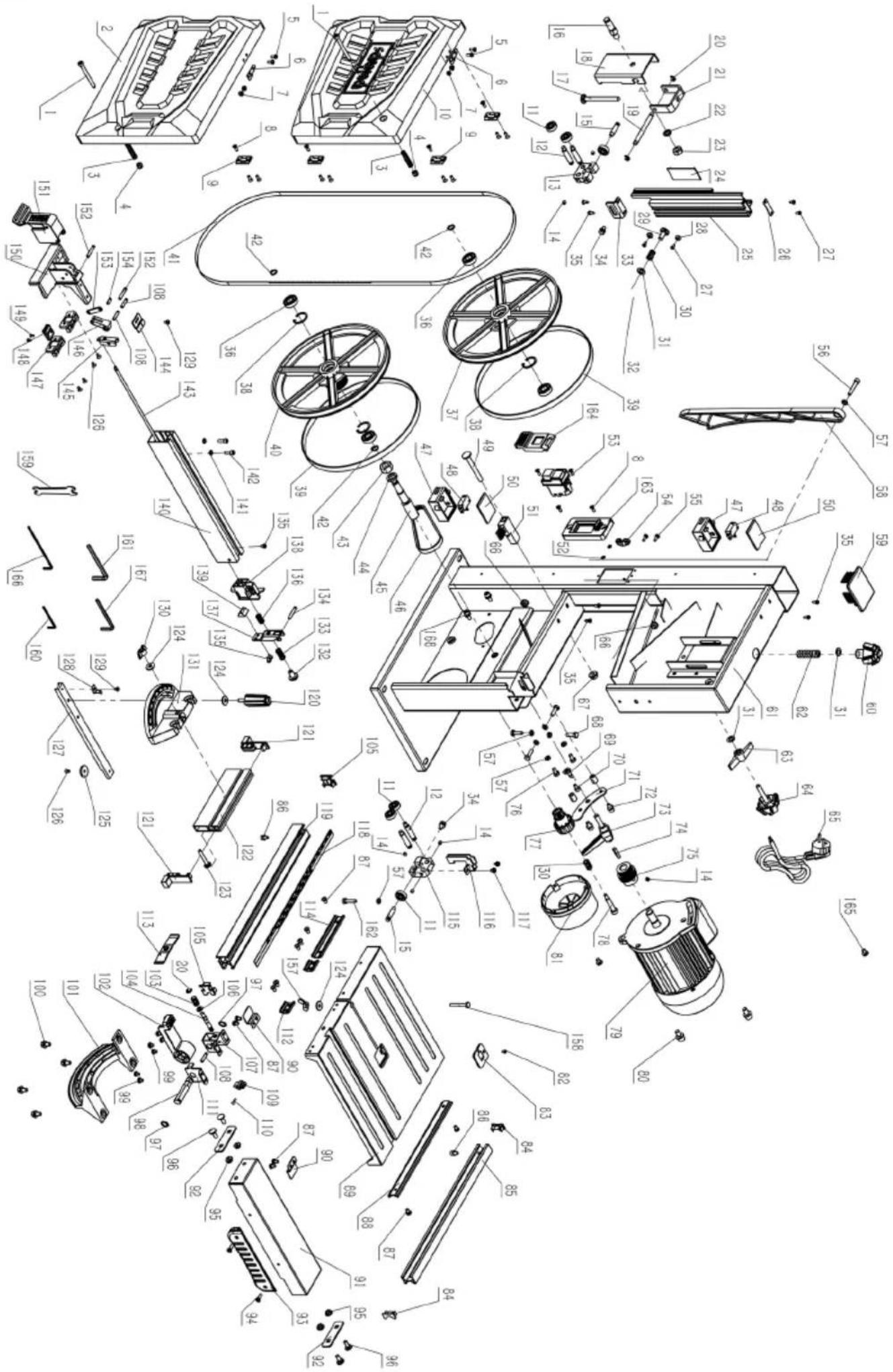
Garantie DE
Obvious defects must be reported within 8 days after receipt of the goods, otherwise the purchaser loses all claims due to such defects. We guarantee our machines, if handled correctly, for the duration of the statutory warranty period from handover in such a way that we will replace free of charge any machine part that demonstrably becomes unusable within this period as a result of material or manufacturing defects. For parts that we do not manufacture ourselves, we only provide a warranty to the extent that we are entitled to warranty claims against the upstream suppliers. The purchaser shall bear the costs of fitting the new parts. Claims for conversion and reduction and other claims for damages are excluded.