HC550TC - Compressor SCHEPPACH - Free user manual and instructions
Find the device manual for free HC550TC SCHEPPACH in PDF.
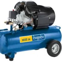
| Product type | Piston air compressor |
| Brand | Scheppach |
| Model | HC550TC |
| Power supply | 230 V / 50 Hz |
| Motor power | 2200 W / 3 HP |
| Tank volume | 100 liters |
| Operating pressure | 10 bar |
| Theoretical intake flow rate | 550 l/min |
| Theoretical output flow rate | 350 l/min |
| Motor speed | 2900 min-1 |
| Oil type | 15W40, 1.2 liters |
| Protection rating | IPX2 |
| Sound power level | 97 dB |
| Weight | 84 kg |
| Dimensions (L x W x H) | Approximately 120 x 50 x 80 cm (estimated) |
| Main functions | Generation of compressed air for pneumatic tools, inflation, painting |
| Maintenance and cleaning | Clean regularly, drain condensation water, change oil every 50 h, clean air filter every 300 h |
| Safety | Safety valve, pressure switch, overload switch, motor thermal protection |
| Spare parts and repairability | Wear parts (air filter, belt, seals) available via after-sales service |
Frequently Asked Questions - HC550TC SCHEPPACH
User questions about HC550TC SCHEPPACH
0 question about this device. Answer the ones you know or ask your own.
Ask a new question about this device
Download the instructions for your Compressor in PDF format for free! Find your manual HC550TC - SCHEPPACH and take your electronic device back in hand. On this page are published all the documents necessary for the use of your device. HC550TC by SCHEPPACH.
USER MANUAL HC550TC SCHEPPACH
natural_image
Exterior view of a Schpeppach air compressor unit (no signage or text beyond branding)
Made in P.R.C.
HC550TC 230V
| DE | KompressorOriginalbetriebsanleitung | 6 |
| GB | CompressorTranslation of original instruction manual | 21 |
| FR | CompresseurTraduction des instructions d'origine | 33 |
| IT | CompressoreLa traduzione dal manuale di istruzioni originale | 46 |
| NL | CompressorVertaling van de originele gebruikshandleiding | 59 |
| ES | CompresorTraducción del manual de instrucciones original | 72 |
| PT | CompressorTradução do manual de operação original | 85 |
| CZ | KompresorPřeklad originálního návodu k obsluze | 98 |
| SK | KompresorPreklad originálneho návodu na obsluhu | 110 |
| HU | KompresszorEredeti használati utasítás fordítása | 122 |
| PL | KompresorTłumaczenie oryginalnej instrukcji obsługi | 134 |
| HR | KompresorPrijevod originalnog priručnika za uporabu | 147 |
| SI | KompresorPrevod originalnih navodil za uporabo | 159 |
| EE | KompressorOriginaalkältusjuhendi tõlge | 171 |
| LT | KompresoriusOriginalios naudojimo instrukcijos vertimas | 182 |
| LV | KompresorsOriginaläs lietošanas instrukcijas tulkojums | 194 |
| SE | KompressorÖversättning av original-bruksanvisning | 206 |
| FI | KompressoriKäännös alkuperäisestä käyttöohjeesta | 218 |
| DK | KompressorOversættelse fra den oprindelige betjeningsvejledning | 230 |
| NO | KompressorOversettelse av den originale brukerveiledningen | 242 |
| BG | KomprecopПревод на оригиналното ръководство за експлоатация | 254 |
| GR | ΣυμπιεστήςΜετάφραση του πρωτοτύπου των οδηγιών χρήσης | 268 |
| RO | CompresorTraducere din manualul de exploatare original | 282 |
| RS | KompresorPrevod originalnog uputstva za upotrebu | 294 |
| TR | KompresörOrijinal kullanım talimatı çevirisi | 306 |
Günzburger Straße 69
D-89335 Ichenhausen
Verehrter Kunde,
Homepage: https://www.scheppach.com/de/service
Explanation of the symbols on the product
Symbols are used in this manual to draw your attention to potential hazards. The safety symbols and the accompanying explanations must be fully understood. The warnings themselves will not rectify a hazard and cannot replace proper accident prevention measures.
 | Warning - Read the operating manual to reduce the risk of injury. |
 | Wear hearing protection. Excessive noise can result in a loss of hearing. |
 | Wear a dust protection mask. When machining wood and other materials, harmful dust may be generated. Do not machine material containing asbestos! |
 | Wear safety goggles. Sparks created during work or fragments, chippings and dust ejected by the product can cause sight loss. |
 | Warning of hot surfaces |
 | Warning against electrical voltage |
 | Warning! The device is equipped with an automated start-up control. Keep third-parties away from the working range of the device! |
 | Do not expose the machine to rain. The unit may only be stationed, stored and operated in dry ambient conditions. |
 | Specification of the sound power level in dB |
| ⚠ Attention! | We have marked points in these operating instructions that impact your safety with this symbol. |
 | Attention! Prior to initial commissioning, check the oil level and replace the oil plug! |
 | The product complies with the applicable European directives. |
 | The product complies with the applicable Serbian directives. |
Table of contents: Page:
- Introduction....23
- Product description (Fig. 1-13) 23
- Scope of delivery 23
- Proper use 23
- General safety instructions.... 24
- Residual risks 26
- Technical data....26
- Unpacking....26
- Layout 27
- Before commissioning 27
- Start-up 28
- Electrical connection 28
- Cleaning....29
- Transport....29
- Storage 29
- Maintenance 29
- Disposal and recycling.... 31
- Troubleshooting 32
- Declaration of conformity 321
1. Introduction
Manufacturer:
Scheppach GmbH
Günzburger Straße 69
D-89335 Ichenhausen
Dear Customer,
We hope your new product brings you much enjoyment and success.
Note:
In accordance with the applicable product liability laws, the manufacturer of this product assumes no liability for damage to the product or caused by the product arising from:
- Improper handling
- Failure to comply with the operating manual
• Repairs carried out by third parties, unauthorised specialists
• Installing and replacing non-original spare parts - Improper use
- Failure of the electrical system in the event of the electrical regulations and VDE provisions 0100, DIN 57113 / VDE 0113 not being observed
Note:
The operating manual is part of this product. It includes important instructions for the safe, proper and economic operation of the product, for avoiding danger, for minimising repair costs and downtimes and for increasing the reliability and extending the service life of the product. In addition to the safety instructions in this operating manual, you must also observe the regulations applicable to the operation of the product in your country.
Familiarise yourself with all operating and safety instructions before using the product. Only operate the product as described and for the specified areas of application. Keep the operating manual in a good place and hand over all documents when passing the product on to third parties.
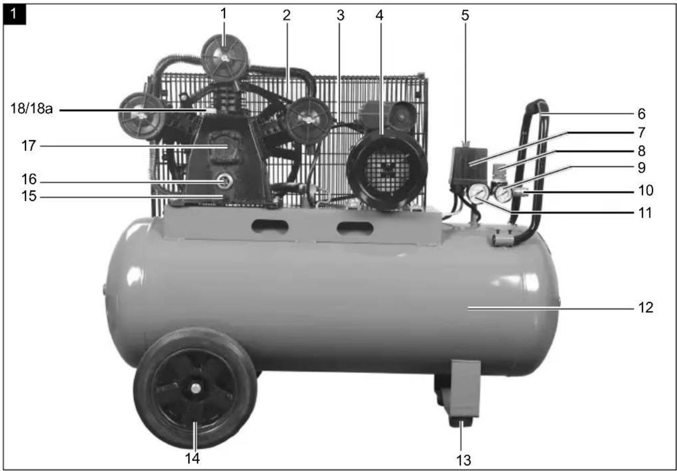
2. Product description (Fig. 1-13)
- Air filter housing
1a. Wing nut
1b. Washer - Protective grate
2a. Screw
2b. Washer -
V-belt
-
Motor
4a. Screw - On/off switch
- Transport handle
6a. Screw - Pressure switch
- Pressure regulator
- Pressure gauge (set pressure can be read off)
- Quick coupling (regulated compressed air)
- Pressure gauge (vessel pressure can be read off)
- Pressure vessel
- Foot
13a. Screw
13b. Nut - Wheel
14a. Screw
14b. Nut - Oil drain screw
- Oil sight glass
- Compressor pump
- Oil plug
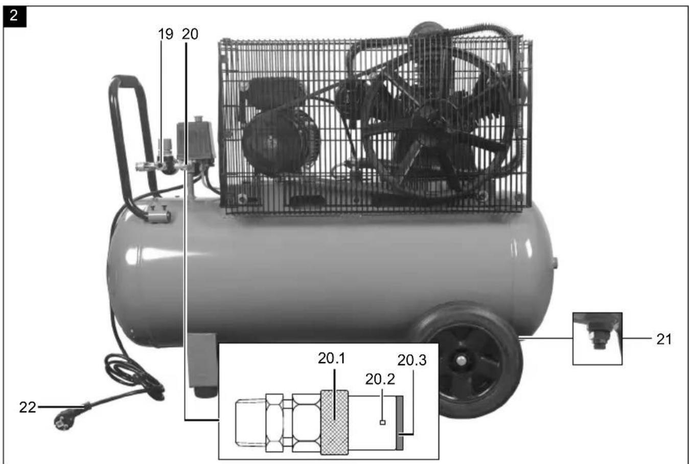
18a. Oil plug transport lock - Quick coupling (regulated compressed air)
- Safety valve
- Drain screw for condensate
- Mains cable
- Plastic clips
- Overload switch
3. Scope of delivery
| 1x | Compressor |
| 3x | Air filter |
| 2x | Foot |
| 2x | Wheel |
| 1x | Assembly material |
| 1x | Transport handle |
| 1x | Oil bottle |
| 1x | Operating manual |
4. Proper use
The compressor is designed to generate compressed air for compressed-air driven tools which can be driven with an air volume of up to approx. 350 l/min (e.g. tyre inflator, blow-out pistol and paint spray gun).
The compressor may only be operated in a dry and well ventilated indoor space.
The product may only be used in the intended manner. Any use beyond this is improper. The user/operator, not the manufacturer, is responsible for damages or injuries of any type resulting from this.
An element of the intended use is also the observance of the safety instructions, as well as the assembly instructions and operating information in the operating manual.
Persons who operate and maintain the product must be familiar with the manual and must be informed about potential dangers.
The liability of the manufacturer and resulting damages are excluded in the event of modifications of the product.
The product may only be operated with original parts and original accessories from the manufacturer.
The safety, operating and maintenance specifications of the manufacturer, as well as the dimensions specified in the technical data, must be observed.
Please note that our products were not designed with the intention of use for commercial or industrial purposes. We assume no guarantee if the product is used in commercial or industrial applications, or for equivalent work.
The manufacturer is not liable for damage caused by improper use or incorrect operation.
5. General safety instructions
⚠ Attention!
The following basic safety measures must be observed when using power tools for protection against electric shock, and the risk of injury and fire. Read all these notices before using the power tool and store the safety instructions well for later reference.
Safe work
- Keep the work area orderly
-
Disorder in the work area can lead to accidents.
-
Take environmental influences into account
- Do not expose power tools to rain.
- Do not use electric tools in a damp or wet environment. There is a risk of electric shock!
- Make sure that the work area is well-illuminated.
-
Do not use power tools where there is a risk of fire or explosion.
-
Protect yourself from electric shock
-
Avoid physical contact with earthed parts (e.g. pipes, radiators, electric ranges, cooling units).
-
Keep away from children!
-
Do not allow other persons to touch the tool and cable, keep them away from your work area.
-
Securely store unused power tools
- Unused power tools should be stored in a dry, elevated or closed location out of the reach of children.
- Do not overload your power tool
- They work better and more safely in the specified output range.
- Wear suitable clothing
- Do not wear wide clothing or jewellery, which can become entangled in moving parts.
- Rubber gloves and anti-slip footwear are recommended when working outdoors.
- Tie long hair back in a hair net.
- Do not use the cable for purposes for which it is not intended
- Do not use the cable to pull the plug out of the outlet. Protect the cable from heat, oil and sharp edges.
- Take care of your tools
- Keep your compressor clean in order to work well and safely.
- Follow the maintenance instructions.
- Check the connection cable of the electric tool regularly and have it replaced by a recognised specialist when damaged.
- Check extension cables regularly and replace them when damaged.
- Pull the connector out of the socket
- When the power tool is not in use or prior to maintenance and when replacing tools such as saw blades, drills, cutters.
- Avoid inadvertent starting
- Make sure that the switch is switched off when plugging the plug into an outlet.
- Use extension cables for outdoors
- Only use approved and appropriately identified extension cables for use outdoors.
- Only use cable reels in the unrolled state.
- Always remain attentive
- Pay attention to what you are doing. Remain sensible when working. Do not use the power tool when you are distracted.
- Check the power tool for potential damage
- Protective devices or other parts with minor damage must be carefully inspected to ensure that they function correctly and as intended prior to continued use of the power tool.
- Check whether the moving parts function faultlessly and do not jam or whether parts are damaged. All parts must be correctly mounted and
all conditions must be fulfilled to ensure fault-free operation of the power tool.
- Damaged protective devices and parts must be repaired as intended or replaced by a recognised specialist workshop unless otherwise specified in the operating instructions.
- Damaged switches must be replaced at a customer service workshop.
- Do not use any faulty or damaged connection cables.
- Do not use any power tool on which the switch cannot be switched on and off.
- Have your electric tool repaired by a qualified electrician.
- This power tool conforms to the applicable safety regulations. Repairs may only be performed by an electrician using original spare parts. Otherwise accidents can occur.
- Attention!
- For your own safety, only use accessories and additional equipment that are indicated in the operating manual or have been recommended or indicated by the manufacturer. Use of other tools or accessories that those recommended in the operating manual or in the catalogue could represent a personal danger to you.
- Noise
- Wear hearing protection when using the compressor.
- Replacing the connection line
- If the connection line is damaged, it must be replaced by the manufacturer or an electrician to avoid danger. There is a risk of electric shock.
- Inflating tyres
- Check the tyre pressure immediately after filling using a suitable pressure gauge, e.g. at a petrol station.
- Street-legal compressors in construction site operation
- Ensure that all hoses and fixtures are suitable for the maximum permissible working pressure of the compressor.
- Set-up location
- Only set up the compressor on a flat surface.
-
In case of pressures above 7 bar, it is recommended to equip supply hoses with a safety cable (e.g. a wire rope).
-
Avoid over-stressing the piping system by using flexible hose connections to prevent kinking.
-
Make sure that the oil cooling devices are kept clean and that the protective devices are kept in good operating condition.
-
Risk of burns from hot oil
- Wear suitable protective gloves.
- Never work with the compressor near naked flames.
- Be careful not to spill oil.
- Starting the motor is forbidden if the temperature is below 0^ C.
Additional safety instructions
Safety instructions for working with compressed air and air blow guns
- Compressor pump and lines reach high temperatures during operation. Touching them will cause burns.
- The air which is sucked in by the compressor must be kept free of impurities that could cause fires or explosions in the compressor pump.
- When disconnecting the hose coupling, hold the coupling piece of the hose firmly with your hand. This will ensure that you avoid injuries caused by the hose recoiling.
- Wear safety goggles when working with the air blow gun. Foreign objects or blown off parts can easily cause injuries.
- Do not blow on people or clean clothing whilst on the body with the air blow gun. Danger of injury!
Safety instructions for spray painting
- Do not process any paints or solvents with a flash point below 55^ C. Risk of explosion!
- Do not heat up paints or solvents. Risk of explosion!
- If harmful liquids are processed, filter devices (face masks) are required for protection. Also observe the information on protective measures provided by the manufacturers of such substances.
- The information and labelling of the hazardous substances ordinance affixed to the outer packaging of the processed materials must be observed. If necessary, take additional protective measures, in particular wear suitable clothing and masks.
- Do not smoke during the spraying process or in the working area. Risk of explosion! Paint vapours are also highly flammable.
- Fireplaces, naked flames lights or sparking machinery must not be present or operated.
- Do not store or consume food or drinks in the work area. Paint fumes are harmful to health.
- The working area must be larger than 30 m ^3 and sufficient air exchange must be ensured during spraying and drying.
- Do not spray into the wind. Always observe the regulations of the local police authorities when spraying flammable or hazardous spraying materials.
- Do not use media such as white spirit, butyl alcohol and methylene chloride in conjunction with the PVC pressure hose. These media destroy the pressure hose.
- When using in conjunction with spraying accessories (e.g. a paint spray gun): Keep the spray attachments away from the product when filling and do not spray towards the compressor.
Operation of pressure vessels
- Anyone who operates a pressure vessel must keep this in good working order, operate and monitor it correctly, perform the necessary maintenance and servicing works immediately and implement safety measures as required according to the circumstances.
- The regulatory authority can instruct necessary monitoring measures in individual cases.
- A pressure vessel must not be operated if it exhibits a defect that poses a danger to personnel or third parties.
- Check the pressure vessel for rust and damage each time before use. The compressor shall not be operated if the pressure vessel is damaged or rusty. If you discover damage, please contact the customer service workshop.
Store the safety instructions safely.
WARNING! This power tool generates an electromagnetic field during operation. This field can impair active or passive medical implants under certain circumstances. In order to prevent the risk of serious or deadly injuries, we recommend that persons with medical implants consult with their physician and the manufacturer of the medical implant prior to operating the power tool.
6. Residual risks
The product has been built according to state-of-the-art and the recognised technical safety rules. However, individual residual risks can arise during operation.
• Health hazard due to electrical power, with the use of improper electrical connection cables.
• Furthermore, despite all precautions having been met, some non-obvious residual risks may still remain.
- Residual risks can be minimised if the "Safety Instructions" and the "Intended Use" together with the operating manual as a whole are observed.
- Avoid accidental starting of the product: the operating button may not be pressed when inserting the plug in a socket. Use the tool attachment that is recommended in this operating manual. This is how to ensure that your product provides optimum performance.
- Keep your hands away from the working area when the product is in operation.
7. Technical data
Mains power connection 230 V / 50 Hz
| Motor output 2200 W / 3 PS | |
| Operating mode S1 | |
| Motor speed 2900 rpm | |
| Pressure vessel volume 100 l | |
| Operating pressure 10 bar | |
| Theo. Suction capability 550 l/min | |
| Theo. Power output 350 l/min | |
| Protection category IPX2 | |
| Weight | 84 kg |
| Oil (15W 40) | 1.2 l |
| Max. installation altitude (above sea level) | 1000 m |
| Belt type | A-1400 |
Subject to technical changes!
Noise and vibration
⚠ Warning: Noise can have serious effects on your health. If the machine noise exceeds 85 dB, please wear suitable hearing protection.
Noise data
| Sound power level L_WA | 97 dB |
| Sound pressure level L_pA | 84.6 dB |
| Uncertainty K_WA/pA | 2.39 / 3 dB |
8. Unpacking
- Open the packaging and carefully remove the product.
- Remove the packaging material, as well as the packaging and transport safety devices (if present).
-
Check whether the scope of delivery is complete.
-
Check the product and accessory parts for transport damage. In the event of complaints the carrier must be informed immediately. Later claims will not be recognised.
- If possible, keep the packaging until the expiry of the warranty period.
- Familiarise yourself with the product by means of the operating manual before using for the first time.
- With accessories as well as wearing parts and replacement parts use only original parts. Spare parts can be obtained from your specialist dealer.
- When ordering please provide our article number as well as type and year of manufacture for the product.
⚠ WARNING!
The product and the packaging material are not children's toys! Do not let children play with plastic bags, films or small parts! There is a danger of choking or suffocating!
9. Layout
ATTENTION!
Always make sure the product is fully assembled before commissioning!
You require the following for assembly:
- 12 mm* open-ended spanner
• 14 mm* open-ended spanner
• 17 mm* open-ended spanner - 4mm^* open-ended spanner
• Phillips screwdriver *
* may not be included in the scope of delivery!
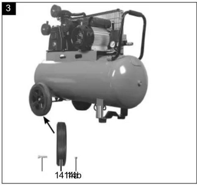
9.1 Fitting the wheels (fig. 3)
- Insert the screw (14a) through the wheel (14).
- Now insert the screw (14a) through the mount on the pressure vessel (12).
- Now insert the screw (14a) with the nut (14b).
- Repeat the process on the other side of the pressure vessel (12).
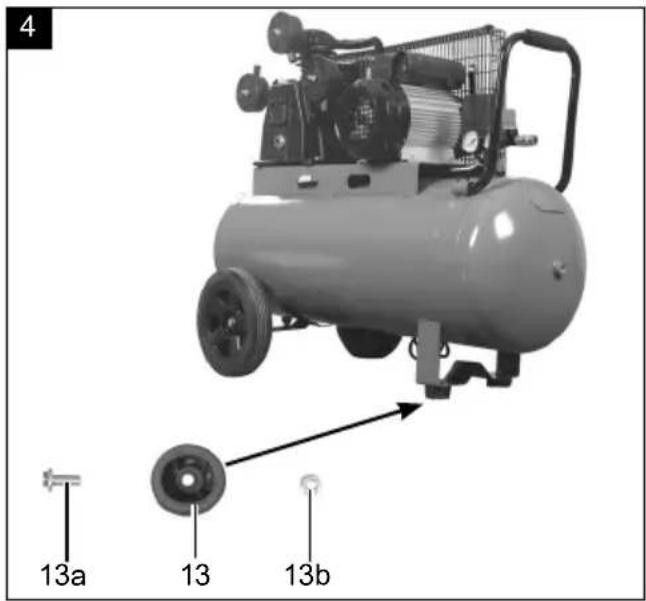
9.2 Mounting the foot (2x) (Fig. 4)
- Insert the screw (13a) through the foot (13).
- The foot (13) is subsequently fitted on the mount on the pressure vessel (12).
- Fasten the foot (13) with the nut (13b).
- Repeat the process for the second foot.
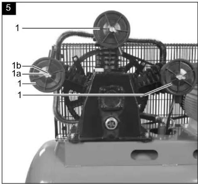
9.3 Installing the air filter (3x) (Fig. 5)
- Remove the transport protection from the air filter mount (if applicable).
- Remove the wing nut (1a) and washer (1b) from the threaded pin on the compressor pump.
- Fit the air filter housing (1) with the air filter on the threaded pin.
- Refasten the air filter housing (1) with the washer (1b) and wing nut (1a).
- Repeat the process with all three air filters.
- Fasten the air filter with the inlet opening facing downwards, to avoid excessive contamination.
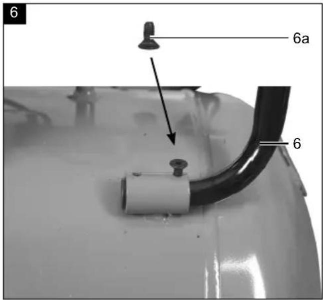
9.4 Mounting the transport handle (Fig. 6)
- Attach the transport handle (6) to the pressure vessel (12) with the screw (6a) as shown.
- Repeat this process three times.
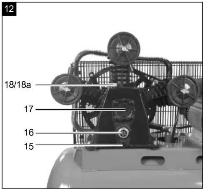
9.5 Filling the compressor oil into the compressor pump housing (Fig. 12)
- Remove the oil plug (18a) from the oil filling opening to secure the transport.
- Fill the compressor oil supplied into the compressor pump housing and fit the oil plug (18) into the oil filling opening.
- Check the oil level using the oil sight glass (16). The oil level must be within the red circle.
10. Before commissioning
- Before connecting the machine, make certain that the data on the type plate matches with the mains power data.
- Fill the compressor pump housing with oil as described in point 9.5.
- Check the product for transport damage. Report any damage immediately to the transport company which was used to deliver the compressor.
• Install the compressor near the point of consumption. - Long air lines and supply cables (extension cable) should be avoided.
- Ensure that the intake air is dry and dust-free.
- Do not install the compressor in a damp or wet room.
- Operate the compressor only in suitable areas (well ventilated, ambient temperature +5°C to 40°C). There must be no dust, acids, vapours, explosive gases or inflammable gases in the room.
-
The compressor is designed to be used in dry rooms. It must not be used in areas where splashed water is present.
-
The oil level in the compressor pump must be checked before commissioning.
- The compressor may only be used outdoor briefly when the ambient conditions are dry.
- The compressor must always be kept dry and must not be left outdoors after work is complete.
11. Start-up
ATTENTION!
Always make sure the product is fully assembled before commissioning!
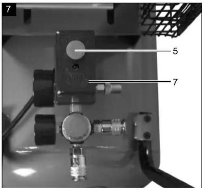
11.1 On/Off switch (fig. 7)
- Pull the on/off switch (5) upwards to switch on the compressor.
- Press the on/off switch (5) down to switch off.
11.2 Adjusting the pressure (fig. 1, 2)
- The pressure at the manometer (9) is adjusted with the pressure regulator (8).
- The adjusted pressure can be drawn from the quick coupling (10, 19).
- The vessel pressure can be read off at the pressure gauge (11).
11.3 Setting the pressure switch (fig. 1)
• The pressure switch (7) is set at the factory.
• Cut-in pressure approx. 8 bar
• Cut-out pressure approx. 10 bar
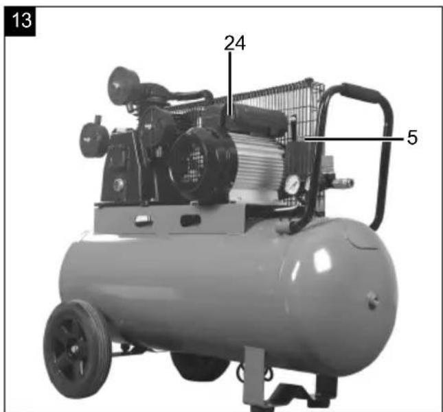
11.4 Overload switch (Fig. 13)
The motor is equipped with an overload switch (24). If the compressor is overloaded, the overload switch (24) switches off automatically to protect the compressor from overheating.
- If the overload switch (24) has triggered, switch the compressor off at the on/off switch (5) and wait until the compressor has cooled down.
- Now press the overload switch (24) and switch the compressor on again.
11.5 Relieving the overpressure after work is complete
- Release overpressure in the compressor by switching off the compressor and using up the compressed air still in the pressure vessel, e.g. with a compressed air tool running at idle or with an air blow gun.
12. Electrical connection
The electrical motor installed is connected and ready for operation. The connection complies with the applicable VDE and DIN provisions. The customer's mains connection as well as the extension cable used must also comply with these regulations.
When working with spray attachments and during temporary use outdoors, the product must be connected to a residual current circuit breaker with a trigger current of 30 mA or less.
Important information
In the event of overloading, the motor will switch itself off. After a cool-down period (time varies) the motor can be switched back on again.
Damaged electrical connection cable
The insulation on electrical connection cables is often damaged.
This may have the following causes:
- Pressure points, where connection cables are passed through windows or doors
- Kinks where the connection cable has been improperly fastened or routed
- Places where the connection cables have been cut due to being driven over
• Insulation damage due to being ripped out of the wall socket
• Cracks due to the insulation ageing
Such damaged electrical connection cables must not be used and are life-threatening due to the insulation damage.
Check the electrical connection cables for damage regularly. Ensure that the connection cables are disconnected from electrical power when checking for damage.
Electrical connection cables must comply with the applicable VDE and DIN provisions. Only use connection cables with the designation H05VV-F.
The printing of the type designation on the connection cable is mandatory.
- The product fulfils the requirements of EN 61000-3-11 and is subject to special connection requirements. This means that use at any freely selectable connection points is not permitted.
- The product can cause temporary voltage fluctuations in unfavourable mains conditions.
- The product is only intended for use at connection points that a) do not exceed a maximum permissible mains impedance "Z" (Zmax. = 0.2117 Ω), or b) have a mains constant current carrying capacity of at least 100 A per phase.
- As the user, you are required to ensure that the connection point at which you wish to operate the product fulfils one of the requirements mentioned, a) or b). If necessary, consult with your energy supplier in this regard.
13. Cleaning
⚠ Attention!
Pull out the mains plug before carrying out any cleaning or maintenance work! Danger of injury due to electric shocks!
⚠ Attention!
Wait until the product has cooled down completely! Danger of burning!
⚠ Attention!
Depressurise the product before carrying out any cleaning or maintenance work! Danger of injury!
- Keep the product as free of dust and dirt as possible. Rub the product clean with a clean cloth or blow it off with compressed air at low pressure.
• We recommend that you clean the product directly after every use. - Clean the product at regular intervals using a damp cloth and a little soft soap.
- Do not use any cleaning products or solvents; they could attack the plastic parts of the product. Make sure that no water can penetrate the interior of the product. Water penetration increases the risk of an electric shock.
- The hose and injection tools must be disconnected from the compressor before cleaning. The compressor must not be cleaned with water, solvents or similar.
14. Transport
• To change the position of the product, lift the transport handle and pull the product to the new location.
- When transporting the product in a vehicle it must be secured to the loading bed with straps.
15. Storage
- Store the product and its accessories in a dark, dry and frost-free place that is inaccessible to children.
- The optimum storage temperature is between 5 and 30^ .
• Store the product in its original packaging.
• Cover the product to protect it from dust or moisture.
• Store the operating manual with the product.
16. Maintenance
You require the following for maintenance:
• 17 mm* open-ended spanner
• 12 mm* open-ended spanner
* may not be included in the scope of delivery!
⚠ Attention!
Pull out the mains plug before carrying out any cleaning or maintenance work! Danger of injury due to electric shocks!
⚠ Attention!
Wait until the product has cooled down completely! Danger of burning!
⚠ Attention!
Depressurise the product before carrying out any cleaning or maintenance work! Danger of injury!
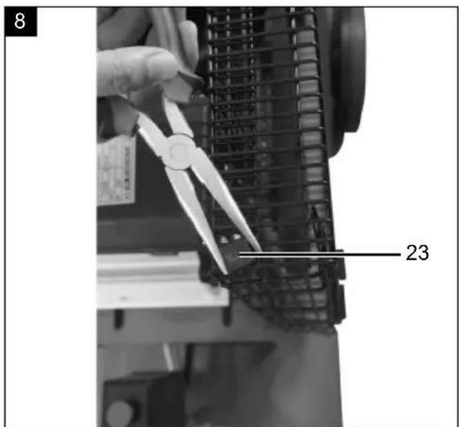
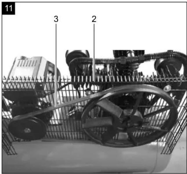
16.1 Replacing the V-belt (Fig. 8 - 11)
- Be sure to disconnect the product from the mains before changing the V-belt (3) on the compressor.
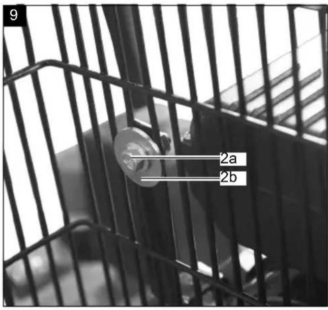
- Remove the protective grate (2) by turning the plastic clips (23) 90° with pliers.
- Take a 12 mm open-ended spanner and remove the screw (2a) and washers (2b) that connect the protective grate (2) to the motor (4).
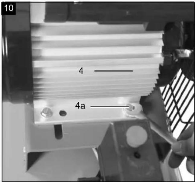
- Open the four screws (4a) on the motor (4) using a 17mm open-ended spanner so that you can then slide the motor.
- Replace the V-belt (3).
- Then carry out the same steps in reverse order to re-store the product to its operating state. Make sure the motor is bolted at a right angle to the running direction, in order to guarantee fault-free running of the V-belt.
16.2 Maintaining the pressure vessel
Attention!
To ensure a long service life for the pressure vessel (12), drain off the condensate after each use by opening the drain screw (21). Release the vessel pressure beforehand (see 11.5).
- The drain screw (21) is opened by turning it anti-clockwise (when looking at the screw on the bottom of the compressor) so that the condensate can be completely drained out of the pressure vessel (12).
- Then close the drain screw (21) again (turn clockwise).
- Check the pressure vessel (12) for rust and damage each time before use.
- The compressor shall not be operated if the pressure vessel (12) is damaged or rusty. If you discover damage, please contact the customer service workshop.
⚠ Attention!
The condensate from the pressure vessel contains oil residue. Dispose of the condensate in an environmentally friendly manner at a suitable collection point.
16.3 Safety valve (Fig. 2)
- The safety valve (20) is set to the maximum permissible pressure of the pressure vessel.
- It is not permitted to adjust the safety valve or to remove the connection lock (20.2) between the drain nut (20.1) and its cap (20.3).
- In order for the safety valve to function properly when needed, it must be actuated every 30 operating hours and at least 3 times a year.
- Turn the perforated drain nut (20.1) anti-clockwise to open it, then pull the valve stem outwards by hand via the perforated drain nut (20.1) to open the safety valve outlet.
- Now, the valve audibly releases air.
- Then turn the drain nut clockwise again to tighten.
16.4 Check the oil level at regular intervals (Fig. 12)
- Place the compressor on a level, even surface.
- The oil level must be at the centre of the oil sight glass (16) (red dot).
16.5 Oil change (Fig. 12)
The original oil filling must be changed after 10 operating hours; afterwards the oil must be drained and replaced with new oil after every 50 operating hours.
16.5.1 Draining oil
-
Switch the motor off and unplug the mains plug from the power outlet.
-
Remove the oil drain screw (15).
- Additionally open the oil plug (18).
- To prevent the oil from running out in an uncontrolled manner, hold a small metal chute under the opening and collect the oil in a vessel. If the oil does not drain out completely, we recommend tilting the compressor slightly.
- Once the oil has fully drained out, replace the oil drain screw (15).
- Dispose of the old oil at a drop-off point for old oil.
16.5.2 Filling in oil
- To fill in the correct quantity of oil, make sure that the compressor stands on an even surface.
- Remove the oil plug (18) and add new oil through the oil filling opening until the oil level in the oil sight glass (16) has reached the correct quantity (red dot). Do not exceed the maximum filling quantity. Overfilling may result in damage to the product.
- Reinsert the oil plug (18) in the oil filling opening.
16.6 Cleaning the air filters (Fig. 5)
The air filters prevent dust and dirt being sucked in. It is necessary to clean this filter at least every 300 operating hours. A blocked air filter significantly reduces the compressor power.
- Remove the air filters by opening the wing nut (1a) on the air filter housing (1).
- Remove the wing nut (1a) and washer (1b).
- Then draw the air filter housing (1) apart. You can now remove the air filter.
- Carefully knock out the air filter and the parts of the filter housing.
- These components must then be blown out with compressed air (approx. 3 bar) and reassembled in reverse order.
16.7 Connections and repairs
Connections and repair work on the electrical equipment may only be carried out by electricians.
Please provide the following information in the event of any enquiries:
• Type of current for the motor
• Machine data - type plate
- Motor data - type plate
Important note in the case of repairs:
For return delivery of the product for repair, please ensure for safety reasons that it is free of oil and fuel when it is sent to the service centre.
Service information
With this product, it is necessary to note that the following parts are subject to natural or usage-related wear, or that the following parts are required as consumables. Wearing parts*: Air filter, V-belt, cylinder, piston, piston rings, plastic clips
* may not be included in the scope of delivery!
Spare parts and accessories can be obtained from our Service Centre. To do this, scan the QR code on the front page.
17. Disposal and recycling
Notes for packaging


The packaging materials are recyclable. Please dispose of packaging in an environmentally friendly manner.
Notes on the electrical and electronic equipment act (ElektroG)
Waste electrical and electronic equipment does not belong in household waste, but must be collected and disposed of separately!
- Used batteries or rechargeable batteries that are not installed permanently in the old device must be removed non-destructively before disposal! Their disposal is regulated by the battery act.
- Owners or users of electrical and electronic devices are legally obliged to return them after use.
- The end user is responsible for deleting their personal data from the old device being disposed of!
- The symbol of the crossed-out dustbin means that waste electrical and electronic equipment must not be disposed of with household waste.
- Waste electrical and electronic equipment can be handed in free of charge at the following places:
- Public disposal or collection points (e.g. municipal works yards)
- Points of sale of electrical appliances (stationary and online), provided that dealers are obliged to take them back or offer to do so voluntarily.
- Up to three waste electrical devices per type of device, with an edge length of no more than 25 centimetres, can be returned free of charge to the manufacturer without prior purchase of a new
device from the manufacturer or taken to another authorised collection point in your vicinity.
- Further supplementary take-back conditions of the manufacturers and distributors can be obtained from the respective customer service.
- If the manufacturer delivers a new electrical device to a private household, the manufacturer can arrange for the free collection of the old electrical device upon request from the end user. Please contact the manufacturer's customer service for this.
- These statements only apply to devices installed and sold in the countries of the European Union and which are subject to the European Directive 2012/19/EU. In countries outside the European Union, different regulations may apply to the disposal of waste electrical and electronic equipment.
You can find out how to dispose of the disused device from your local authority or city administration.
Fuels and oils
- Before disposing of the device, the fuel tank and the motor oil tank must be emptied!
- Fuel and engine oil do not belong in household waste or drains, but must be collected or disposed of separately!
- Empty oil and fuel tanks must be disposed of in an environmentally friendly manner.
18. Troubleshooting
The following table shows fault symptoms and describes remedial measures in the event of your machine failing to work properly. If you cannot localise and rectify the problem with this, please contact your service workshop.
| Fault Possible cause Remedy | ||
| The compressor does not start | Mains voltage not present Check cable, mains plug, fuse and socket | |
| Mains voltage too low Avoid extension cables that are too long. Use extension cables with sufficient conductor cross-section | ||
| Outdoor temperature too low | Do not operate at outside temperatures below +5°C | |
| Motor overheating Allow the motor to cool down.If necessary, remedy the cause of the overheating | ||
| Compressor runs, but no pressure | The safety valve leaks Replace the safety valve | |
| The seals are damaged Check the seals and have any damaged seals replaced by a service centre | ||
| Drain screw for condensate leaking Tghten the screw by hand. Check the seals on the screw and replace if necessary | ||
| Compressor running, pressure shown on the manometer, but tools are not running | Hose connection leaking Check compressed air hose and tool, replace if necessary | |
| Quick-coupler leaking Check quick coupling, replace if necessary | ||
| Pressure set too low at pressure regulator | Turn up the pressure regulator further | |
Günzburger Straße 69
D-89335 Ichenhausen
Cher client,
Günzburger Straße 69
D-89335 Ichenhausen, Germania
Egregio cliente,
Günzburger Straße 69
D-89335 Ichenhausen
Geachte klant,
Günzburger Straße 69
Günzburger Straße 69
Günzburger Straße 69
D-89335 Ichenhausen
Vážený zákazníku,
Günzburger Straße 69
D-89335 Ichenhausen
Vážený zákazník,
Günzburger Straße 69
D-89335 Ichenhausen
Kedves Ügyfelünk!
Günzburger Straße 69
D-89335 Ichenhausen
Szanowny Kliencie,
Günzburger Straße 69
D-89335 Ichenhausen
Poštovani kupci,
želimo vam mnogo zadovoljstva i uspjeha pri radu s novim proizvodom.
Napomena:
Prema važećem njemačkom Zakonu o odgovornosti za proizvode, proizvođač ovog proizvoda ne odgovara za štete koje nastanu na ovom proizvodu ili koje ovaj proizvod uzrokuje u slučaju:
- neispravnog rukovanja
- Nepridržavanje priručnika za uporabu
- popravaka koje obave drugi, neovlašteni stručnjaci
- montaže i zamjene neoriginalnih rezervnih dijelova
- nenamjenske uporabe
- kvarova električnog sustava zbog nepoštivanja električnih propisa i VDE propisa 0100, DIN 57113 / VDE 0113
Günzburger Straße 69
D-89335 Ichenhausen
Spoštovani kupec,
želimo vam veliko veselja in uspeha pri delu z vašim novim izdelkom.
Napotek:
Proizvajalec tega izdelka skladno z veljavnim zakonom o odgovornosti za izdelke ne jamči za poškodbe na tem izdelku ali poškodbe s tem izdelkom, do katerih pride pri:
Günzburger Straße 69
D-89335 Ichenhausen
Austatud klient!
Günzburger Straße 69
D-89335 Ichenhausen
Gerbiamas kliente,
Günzburger Straße 69
Günzburger Straße 69
D-89335 Ichenhausen
Bästa kund!
Günzburger Straße 69
D-89335 Ichenhausen
Arvoisa asiakas,
Günzburger Straße 69
D-89335 Ichenhausen, Tyskland
Kære kunde,
Günzburger Straße 69
D-89335 Ichenhausen
Kjære kunde,
Günzburger Straße 69
D-89335 Ichenhausen, Германия
Уважаеми клиенти,
Günzburger Straße 69
D-89335 Ichenhausen
Αξιότιμε πελάτη,
Günzburger Straße 69
D-89335 Ichenhausen
Stimate client,
Günzburger Straße 69
D-89335 Ichenhausen
Poštovani kupče,
Günzburger Straße 69
D-89335 Ichenhausen
İthalatçı:
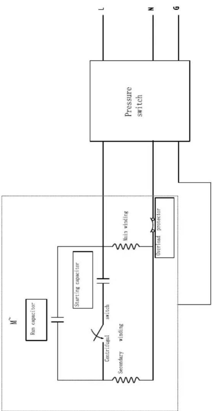
flowchart
graph TD
    A["Run capacitor"] --> B["Starting capacitor"]
    B --> C["Centrifugal switch"]
    C --> D["Secondary winding"]
    D --> E["Overload protector"]
    E --> F["Pressure switch"]
    F --> G["L"]
    F --> H["N"]
    F --> I["G"]
EU Declaration of Conformity
| X 2006/42/EG | |
| Annex IV Notified Body: Notified Body No.: Certificate No.: | |
| X 2000/14/EG_2005/88/EG | |
| Noise: measured LWA = 94,2 dB; guaranteed LWA = 97 dB | |
| Annex V | |
| Annex VI P = xx KW; L/Ø = cm Notified Body: TÜV Süd Industrie Service Westendstr. 199, 80686 München Notified Body No.: 0036 | |
| 2016/1628/EU | |
| Emission. No: | |
Standard references:
EN 1012-1:2010; EN 60204-1:2018;
EN 55014-1:2021; EN 55014-2:2021; EN IEC 61000-3-2:2019/A1:2021; EN IEC 61000-3-11:2019
This declaration of conformity is issued under the sole responsibility of the manufacturer.
The object of the declaration described above fulfils the regulations of the directive 2011/65/EU of the European Parliament and Council from 8th June 2011, on the restriction of the use of certain hazardous substances in electrical and electronic equipment.
Subject to change without notice
Documents registrar: Matthias Herz
Günzburger Str. 69, D-89335 Ichenhausen
EU Declaration of Conformity
Article name: COMPRESSOR - HC550TC-230V
| X | 2006/42/EG | |
| Annex IV Notified Body: Notified Body No.: Certificate No.: | ||
Standard references:
EN 1012-1:2010; EN 60204-1:2018;
EN 55014-1:2021; EN 55014-2:2021; EN IEC 61000-3-2:2019/A1:2021; EN IEC 61000-3-11:2019
This declaration of conformity is issued under the sole responsibility of the manufacturer.
The object of the declaration described above fulfils the regulations of the directive 2011/65/EU of the European Parliament and Council from 8th June 2011, on the restriction of the use of certain hazardous substances in electrical and electronic equipment.
Subject to change without notice
Documents registrar: Matthias Herz
Günzburger Str. 69, D-89335 Ichenhausen
EU-Konformitätserklärung EU Declaration of Conformity AB uygunluk beyani
Article name: COMPRESSOR - HC550TC-230V
Standard references:
EN 1012-1:2010; EN 60204-1:2018;
EN 55014-1:2021; EN 55014-2:2021; EN IEC 61000-3-2:2019/A1:2021; EN IEC 61000-3-11:2019
This declaration of conformity is issued under the sole responsibility of the manufacturer.
The object of the declaration described above fulfils the regulations of the directive 2011/65/EU of the European Parliament and Council from 8th June 2011, on the restriction of the use of certain hazardous substances in electrical and electronic equipment.
Subject to change without notice
Documents registrar: Matthias Herz
Günzburger Str. 69, D-89335 Ichenhausen
Garantie DE
Apparent defects must be notified within 8 days from the receipt of the goods. Otherwise, the buyer loses its rights of claim due to such defects are invalidated. We guarantee for our machines in case of proper treatment for the time of the statutory warranty period from delivery in such a way that we replace any machine part free of charge which provably becomes unusable due to faulty material or defects of fabrication within such period of time. With respect to parts not manufactured by us we only warrant insofar as we are entitled to warranty claims against the upstream suppliers. The costs for the installation of the new parts shall be borne by the buyer. The cancellation of sale or the reduction of purchase price as well as any other claims for damages shall be excluded.
Garantie FR
Apparent defects must be notified within 8 days from the receipt of the goods. Otherwise, the buyer's rights of claim due to such defects are invalidated. We guarantee for our machines in case of proper treatment for the time of the statutory warranty period from delivery in such a way that we replace any machine part free of charge which provably becomes unusable due to faulty material or defects of fabrication within such period of time. With respect to parts not manufactured by us we only warrant insofar as we are entitled to warranty claims against the upstream suppliers. The costs for the installation of the new parts shall be borne by the buyer. The cancellation of sale or the reduction of purchase price as well as any other claims for damages shall be excluded.
Záruka CZ
Apparent defects must be notified within 8 days from the receipt of the goods. Otherwise, the buyer's rights of claim due to such defects are invalidated. We guarantee for our machines in case of proper treatment for the time of the statutory warranty period from delivery in such a way that we replace any machine part free of charge which provably becomes unusable due to faulty material or defects of fabrication within such period of time. With respect to parts not manufactured by us we only warrant insofar as we are entitled to warranty claims against the upstream suppliers. The costs for the installation of the new parts shall be borne by the buyer. The cancellation of sale or the reduction of purchase price as well as any other claims for damages shall be excluded.
Garantii EE
Apparent defects must be notified within 8 days from the receipt of the goods. Otherwise, the buyer's rights of claim due to such defects are invalidated. We guarantee for our machines in case of proper treatment for the time of the statutory warranty period from delivery in such a way that we replace any machine part free of charge which provably becomes unusable due to faulty material or defects of fabrication within such period of time. With respect to parts not manufactured by us we only warrant insofar as we are entitled to warranty claims against the upstream suppliers. The costs for the installation of the new parts shall be borne by the buyer. The cancellation of sale or the reduction of purchase price as well as any other claims for damages shall be excluded.