GHE 355 - Plane STIHL - Free user manual and instructions
Find the device manual for free GHE 355 STIHL in PDF.
| Brand | STIHL |
| Model | GHE 355 |
| Product type | Electric garden shredder |
| Dimensions (L x W x H) | 122 x 50 x 141 cm |
| Weight | 30 kg (standard version) |
| Supply voltage | 230 V ~ (50 Hz) |
| Power consumption | 2500 W (standard), 2000 W (GB/CH) |
| Maximum branch diameter | 35 mm |
| Motor rated speed | 2750 rpm |
| Sound pressure level (L_pA) | 94 dB(A) |
| Guaranteed sound power level | 100 dB(A) |
| Protection class | I |
| Protection type | IPX4 (splash-proof) |
| Shreddable materials | Soft waste (leaves, peelings) and hard waste (branches, hedge trimmings) |
| Hopper capacity | Large feed chute for bulky branches |
| Cutting system | Blade disc with combination, wing, and chopping blades |
| Blade maintenance | Sharpenable, regular wear check |
| Safety devices | Restart lock, locking mechanism, deceleration brake, protective covers |
| Thermal protection | Overload relay with automatic shutdown |
| Wheel diameter | 250 mm |
| Common spare parts | Blade disc (6011 700 5100), blades (multiple references) |
| Warranty and repairability | Maintenance at specialized dealer recommended, spare parts available |
Frequently Asked Questions - GHE 355 STIHL
User questions about GHE 355 STIHL
0 question about this device. Answer the ones you know or ask your own.
Ask a new question about this device
Download the instructions for your Plane in PDF format for free! Find your manual GHE 355 - STIHL and take your electronic device back in hand. On this page are published all the documents necessary for the use of your device. GHE 355 by STIHL.
USER MANUAL GHE 355 STIHL
natural_image
Exterior view of a Stihel cleaning brush (no text or symbols visible on the device body)text_image
Exploded view diagram of a car body with labeled parts including wheel, screw, and bracket components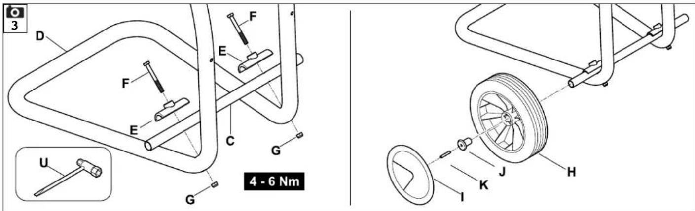
text_image
3 D F E F E C G G U 4 - 6 Nm J K H I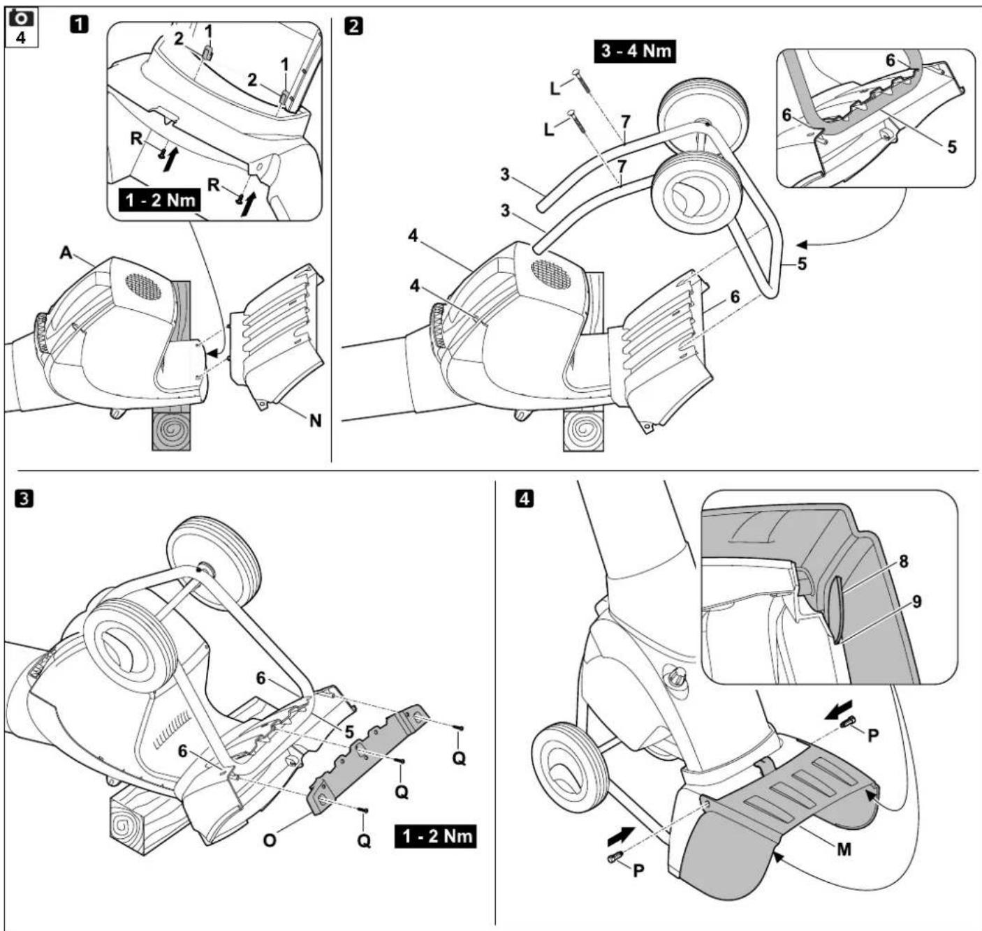
text_image
5 1 CLACK 2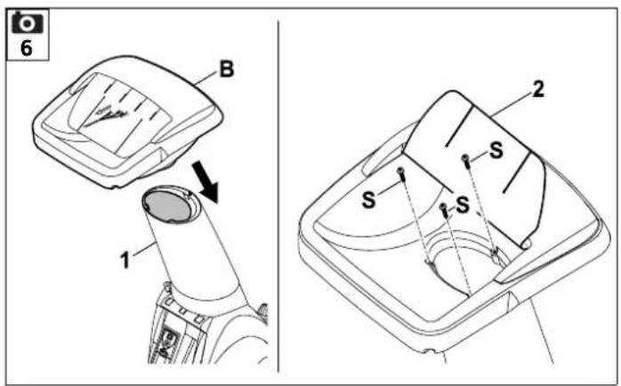
text_image
6 B 1 2 S S S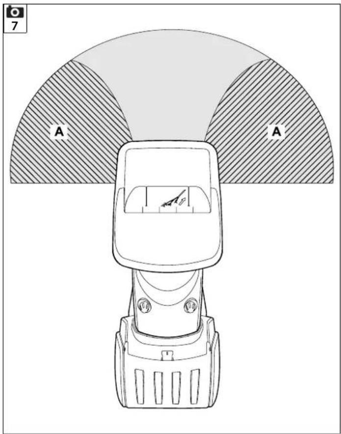
text_image
A A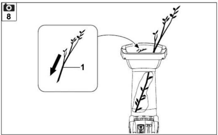
text_image
8 1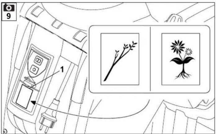
text_image
9 1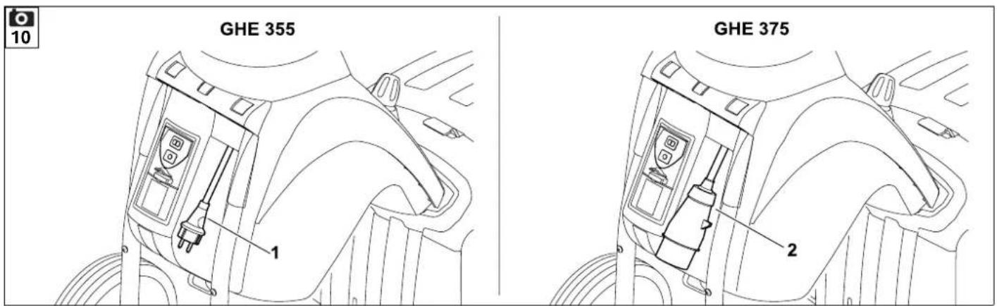
text_image
GHE 355 1 GHE 375 2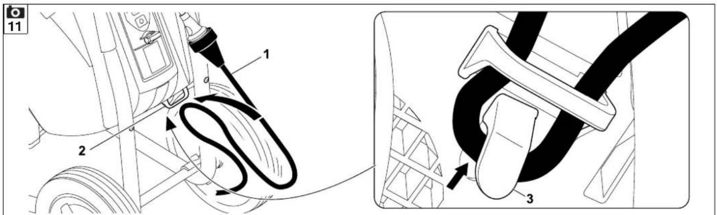
text_image
1 2 3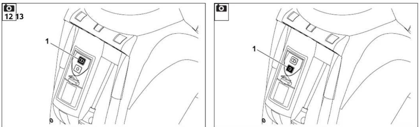
text_image
12 13 1 10478 201 9914 E
text_image
14 2 1 2 1 2 1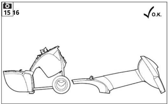
natural_image
Technical line drawing of a mechanical device with two views: top view and side view, no text or symbols present.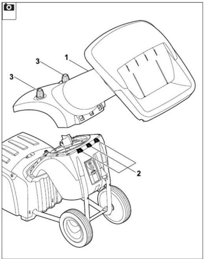
text_image
Technical diagram of a vehicle's internal components with numbered parts, including front and side views.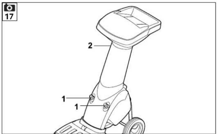
text_image
17 2 1 1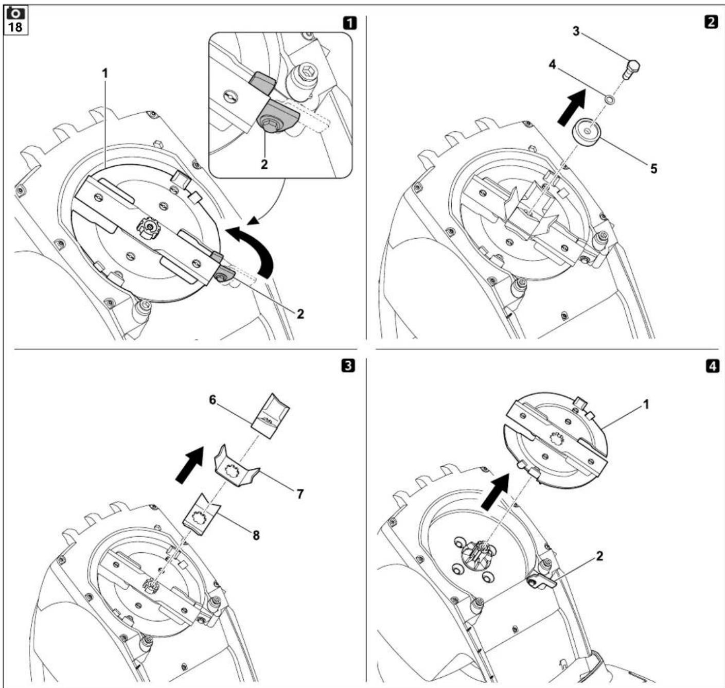
20
text_image
Technical diagram of a mechanical assembly with numbered components for identification1
text_image
1 2 3 4 52
text_image
B 23
text_image
D C D 34
natural_image
Line drawing of a person using a lawn mower to lift a cart, with no text or symbols present.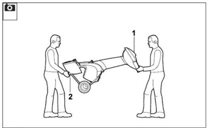
text_image
Diagram showing two people handling a mechanical device with labeled parts 1 and 2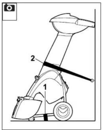
text_image
Technical diagram of a mechanical device with labeled parts 1 and 2, likely for assembly or maintenance instructions.
text_image
2.0 2.0
text_image
2.0 2.0
text_image
2.0 2.0
text_image
2.0 2.0
text_image
2,0 2,0
text_image
2.0 2.0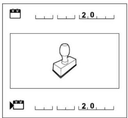
text_image
2.0 2.0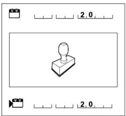
text_image
2.0 2.0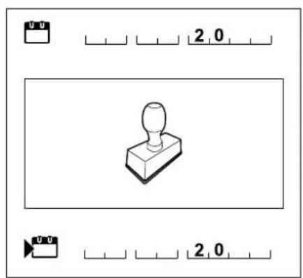
text_image
2.0 2.0text_image
Warning symbol panel with checkmark, warning triangle, Earth icon, cross, and prohibition symbolsVerletzungsgefahr!
Messung gemäß 2000/14/EG / S.I.
2001/1701:
Thank you for choosing STIHL. We develop and manufacture our quality products to meet our customers' requirements. The products are designed for reliability even under extreme conditions.
STIHL also stands for premium service quality. Our specialist dealers guarantee competent advice and instruction as well as comprehensive service support.
We thank you for your confidence in us and hope you will enjoy working with your STIHL product.

Dr. Nikolas Stihl
IMPORTANT: READ BEFORE USE AND KEEP IN A SAFE PLACE.
1. Table of contents
Notes on the instruction manual 38
General 38
Instructions for reading the instruction manual 38
Country-specific versions 38
Machine overview 39
For your safety 39
General 39
Warning – dangers caused by electrical current 40
Clothing and equipment 40
Transporting the machine 40
Before operation 41
Working with your machine 42
Maintenance and repairs 43
Storage for prolonged periods without operation 44
Disposal 44
Description of symbols 44
Standard equipment
Preparing the machine for operation
Attaching wheel axle and wheels 45 Installing the chassis and ejection chute 45
Opening and closing the discharge flap 46
Attaching the upper chute 46
Notes on working with the machine
What material can be processed? 46
What material cannot be processed? 46
Maximum branch diameter 46
Working area for operator 47
Correct way to feed the garden shredder
Display 47
Correct machine load 47
Overload protection 47
If the cutting unit of the garden shredder is blocked 48
Safety devices 48
Motor restart inhibitor 48
Safety interlock 48
Motor run-down brake 48
Protective covers 48
Operating the machine 48
Electrical connection of garden shredders 48
Connecting the power cable 48
Disconnecting the power cable 49
Strain relief 49
Switching on the garden shredder 49
Switching off the garden shredder 49
Preselector switch 49
Shredding 50
Maintenance 50
Cleaning the machine 50
Service intervals 50
Installing the feed chute 50
Removing the feed chute 51
Blade set service intervals 51
Removing the blade set 51
Installing the blade set 51
Wear limits of the blades 51
Sharpening shredding blades 52
Electric motor and wheels 52
Storage and winter break 52
Transport 53
Pulling or pushing the garden shredder 53
Lifting or carrying the garden shredder 53
Transporting the garden shredder on a load floor 53
Minimising wear and preventing damage 53
Standard spare parts 54
Environmental protection 54 Disposal 54
Declaration of conformity 54
EU declaration of conformity –
STIHL GHE 355.0, GHE 375.0
garden shredder 54
UKCA-Declaration of Conformity
STIHL GHE 355.0
Garden Shredder 55
Technical specifications 55
REACH 56
Troubleshooting 56
Service schedule 57
Handover confirmation 57
Service confirmation 57
2. Notes on the instruction manual
2.1 General
This instruction manual constitutes original manufacturer's instructions in the sense of EC Directive 2006/42/EC.
STIHL is continually striving to further develop its range of products; we therefore reserve the right to make alterations to the form, technical specifications and equipment level of our standard equipment.
For this reason, the information and illustrations in this manual are subject to alterations.
This instruction manual may describe models that are not available in all countries.
This instruction manual is protected by copyright. All rights reserved, especially the right of reproduction, translation and processing using electronic systems.
2.2 Instructions for reading the instruction manual
Illustrations and texts describe specific operating steps.
All symbols which are affixed to the machine are explained in this instruction manual.
Viewing direction:
Viewing direction when left and right are used in the instruction manual: the user is standing behind the machine (working position).
Section reference:
References to relevant sections and subsections for further descriptions are made using arrows. The following example shows a reference to a section: ( 4.)
Designation of text passages:
The instructions described can be identified as in the following examples.
Operating steps which require intervention on the part of the user:
- Release screw (1) using a screwdriver, operate lever (2)...
General lists:
– Use of the product for sporting or competitive events
Texts with added significance:
Text passages with added significance are identified using the symbols described below in order to especially emphasise them in the instruction manual:

Danger
Risk of accident and severe injury to persons. A certain type of behaviour is necessary or must be avoided.

Warning
Risk of injury to persons. A certain type of behaviour prevents possible or probable injuries.

Caution
Minor injuries or material damage can be prevented by a certain type of behaviour.

Note
Information for better use of the machine and in order to avoid possible operating errors.
Texts relating to illustrations:
Illustrations relating to use of the machine can be found in the front of this instruction manual.
The camera symbol serves to link the figures on the illustration pages with the corresponding text passages in the instruction manual.

2.3 Country-specific versions
STIHL supplies machines with different plugs and switches, depending on the country of sale.
Machines with European plugs are shown in the illustrations. Machines with other types of plug are connected to the mains in a similar way.
3. Machine overview

1 Basic unit
2 Lower chute
3 Handle
4 Upper chute
5 Closure screws
6 Ejection chute
7 Tubular stand
8 Wheel
9 Switch
10 Strain relief
11 Mains plug GHE 355
12 Mains plug GHE 375
13 Rating plate with machine number
4. For your safety
4.1 General

These safety regulations must be observed when working with the machine.

Read the entire instruction manual before using the machine for the first time. Keep the instruction manual in a safe
place for future reference.
These safety precautions are essential for your safety, however the list is not exhaustive. Always use the machine in a reasonable and responsible manner and be aware that the user is responsible for accidents involving third parties or their property.
Make sure that you are familiar with the controls and use of the machine.
The machine must only be used by persons who have read the instruction manual and are familiar with operation of the machine. The user should seek expert and practical instruction prior to initial operation. The user must receive instruction on safe use of the machine from the vendor or another expert.
During this instruction, the user should be made aware that the utmost care and concentration are required for working with the machine.
Residual risks persist even if you operate this machine according to the instructions.

Risk of death from suffocation! Packaging material is not a toy - danger of suffocation! Keep packaging material away from children.
Only give or lend the machine, including any accessories, to persons who are familiar with this model and how to operate it. The instruction manual forms part of the machine and must always be provided to persons borrowing it.
Make sure that the user is physically, sensorily and mentally capable of operating the machine and working with it. If the user is physically, sensorily or mentally impaired, the machine must only be used under supervision or following instruction by a responsible person.
Make sure that the user is of legal age or being trained under supervision in a profession in accordance with national regulations.
The machine must only be operated by persons who are well rested and in good physical and mental condition. If your health is impaired, you should consult your doctor to determine whether working with the machine is possible. The machine should not be operated after the consumption of alcohol, drugs or medications which impair reactions.
The machine is intended for private use.
Caution – risk of accident!
STIHL garden shredders are suitable for shredding branch material and plant trimmings. Their use for other purposes is not permitted and may be dangerous or result in damage to the machine.
The garden shredder must not be used (incomplete list):
– for any other materials (e.g. glass, metal).
– for tasks other than those described in this instruction manual.
– for the preparation of foodstuffs (e.g. crushing ice, mashing pulp).
For safety reasons, any modification to the machine, except the proper installation of accessories approved by STIHL, is forbidden and results in voiding of the warranty cover. Information regarding approved accessories can be obtained from your STIHL specialist dealer.
In particular, any tampering with the machine which increases the power output or speed of the engine or motor is forbidden.
It is not permitted to transport objects, animals or persons, particularly children, on the machine.
Particular care is required during use in public green spaces, parks, sports fields, along roads and in agricultural and forestry businesses.
Only release the machine if it is on a level surface and cannot roll away by itself.
4.2 Warning – dangers caused by electrical current

Warning: Risk of electric shock!
Particularly important for electrical safety are the power cable, mains plug, On / Off switch and

electric cable. Damaged cables, connectors and plugs, or electric cables that do not conform to regulations must not be used, to prevent any risk of electric shocks.
Therefore, check the electric cable regularly for signs of damage or ageing (brittleness).
Only operate machine with fully uncoiled power cable.
Extension reels must always be fully unwound before use.
Never use a damaged extension cable. Replace defective cables with new ones and never repair extension cables.
If the power cable or extension cable is damaged during operation, immediately disconnect the power cable or extension cable from the power supply. Never touch the damaged power cable or extension cable.
Never use the machine if the cables are damaged or worn. Check the power cable in particular for damage and ageing.
Maintenance and repair work on power cables must only be performed by specially qualified technicians.
Danger of electric shock!
Do not connect a damaged cable to the mains and only touch a damaged cable once it has been disconnected from the mains.
Only touch the cutting units (blades) when the machine is disconnected from the mains.
Always ensure that the power cables used are adequately protected by a fuse.

Do not work in the rain or in a wet environment.
Only use extension cables that are insulated against moisture for outdoor use
which are suitable for use with the machine ( 10.).
Detach electric cables at the plug and socket and not by pulling on the electric cable.
Do not leave the machine unprotected in the rain.
It must be noted that current fluctuations can damage the machine when it is connected to a power generator.
Only connect the machine to a power supply that is protected by means of a residual current-operated protective device with a release current of a maximum of 30 mA. Your electrician can provide further information.
4.3 Clothing and equipment

Always wear sturdy footwear with high-grip soles when working. Never work barefoot ample, in sandals.

Always wear protective leather gloves with a closed cuff during work and especially during maintenance operations and sporting the machine.

Always wear safety glasses and hearing protection when working. Wear them at all times.

Wear suitable, close-fitting clothing when working with the machine, e.g. overalls, but not work coats. Do not wear ties, jewellery, clothing with straps or cords or other articles of clothing when with the machine.
Long hair must be tied up and secured (headscarf, cap, etc.) at all times when operating or performing work on the machine.
4.4 Transporting the machine
Always wear protective gloves ( 4.3) in order to prevent injuries due to sharp-edged and hot components.
Do not transport the machine with the motor running. Switch off the motor, allow the blades to come to a standstill and disconnect the mains plug prior to transport.
Only transport the machine once the motor has cooled down.
Only transport the machine with the feed chute properly fitted
Risk of injury due to exposed blades.
Pay particular attention to the weight of the machine, especially when tilting.
Use suitable loading aids (loading ramps, lifters).
Secure the machine on the load floor using adequately dimensioned fastening material (straps, ropes etc.) at the fastening points described in this instruction manual. ( 12.3)
Push or pull the machine at walking pace only. Do not tow!
When transporting the machine, always observe regional legislation, especially regarding load security and the transport of objects on load floors.
4.5 Before operation
Make sure that only persons who are familiar with the instruction manual are permitted to use the machine.
Observe the local regulations regarding permitted operating times for gardening power tools with combustion engines or electric motors.
All faulty, worn or damaged parts must be replaced before using the machine. Replace any illegible or damaged danger signs and warnings on the machine. Your STIHL specialist has a supply of replacement stickers and all the other spare parts.

Risk of injury!
Worn or damaged parts (e.g. blunt blades) can affect the safety of the machine and result in injury to the user.
Before initial operation, check and ensure the following:
– The machine is in good operational condition. This means that the covers and guards must be in place and in good condition.
- A properly installed socket is used for the electrical connection.
- The insulation of the electric cable, extension cable, plug and connector is in good condition.
– The complete machine (motor housing, guards, fastening elements, blades, blade shaft, blade discs, etc.) is neither worn nor damaged.
– There is no shredding material in the machine and the feed chute is empty.
- All screws, bolts, nuts and other fastening elements are in place and properly tightened. Tighten any loose screws, bolts and nuts prior to initial operation (observe torque).
- The preselector switch was used to preset the type of shredding material (hard or soft material).

Risk of injury!
The setting for the type of shredding material determines the rotational direction of the blades. The user can be seriously injured by shredding material kickback if the setting is incorrect.
Only use the machine out-of-doors and not close to walls or any other solid objects in order to prevent the risk of injuries and property damage (no escape for the user, broken windows, scratched cars etc.).
The machine must placed in a stable position on firm and level ground.
Do not use the machine on a paved or gravel-covered surfaces, as ejected or thrown-up material could cause injuries.
Before using the machine, always check that it is properly closed. ( 11.3)
Make sure that you are familiar with the On / Off switch so that you can react quickly and correctly in any emergency situation.
The splash guard in the feed chute must cover the feed opening and must be undamaged – replace the splash guard if damaged.
Risk of injury:
Only operate the machine when properly assembled. If parts of the machine (e.g. wheels) are missing, the specified safety distances are no longer maintained and the stability of the machine may also be reduced.
Before using the machine, always carry out a visual check to ensure that it is in good operating condition.
"Good operating condition" means that the machine is fully assembled, in particular:
– Upper chute is installed on lower chute
- Feed chute is installed on basic unit and both closure screws are fastened hand-tight
– Wheel carrier assembly is installed
- Both wheels are mounted
- All safety devices (ejection chute, splash guard etc.) must be present and functional
– Cutting unit (blade disc) is installed
– All blades are properly installed
The switch and safety devices installed in the machine must not be removed or bypassed.
Visually inspect the blade disc for damage and deformation; replace if necessary.
4.6 Working with your machine

Never work when animals or people, particularly children, are in the danger area.
Do not operate the machine in the rain or during thunder storms, particularly when there is a risk of lightning strike.
The risk of accidents is higher if the ground is damp due to increased danger of slipping.
Particular caution should be exercised during working in order to prevent slipping. If possible, avoid using the machine when the ground is damp.
Only work during the day or with good artificial light.
Keep the working area neat and tidy at all times. Remove tripping hazards such as stones, branches, cables etc.
The operator should not stand any higher than the level of the base of the machine.
Starting:
Place the machine in a stable and upright position prior to starting. The machine must never be operated in a horizontal position.
Exercise care when switching on the machine and observe the instructions in the section "Operating the machine". ( 10.5)
Do not stand in front of the discharge opening when starting the engine or switching on the motor. There must be no shredding material in the garden shredder when it is started or switched on.
Shredding material may be ejected and lead to injuries.
The machine must not be tilted during start-up.
Avoid switching the machine on repeatedly within a short period of time; particularly avoid "playing" with the On / Off switch. Risk of motor overheating.
Owing to the voltage fluctuations caused by this machine during the start-up, other devices connected to the same circuit may be subject to interference in the case of unfavourable power supply conditions. In this case, appropriate steps should be taken (e.g. connection to a different circuit than the one used by the affected device, or operation of the machine using a circuit with a lower impedance).
Working:

Risk of injury!
Never place your hands or feet above, underneath or on rotating parts.
When the machine is running, never put your face or any other part of your body above the feed chute or in front of the ejection opening. Always keep you head and body away from the feed opening.

Never put your hands or any other part of your body or clothing into the feed chute or ejection chute. There is a
considerable risk of injury to eyes, face, fingers, hands etc.
Always maintain your balance and firm footing. Do not stretch forward.
The splash guard must not be tampered with (removed, folded up, jammed into position, damaged etc.) during operation. The operator must stand in the working area described when feeding the shredder. Stay inside the working area and outside of the ejection zone at all times during operation of the machine. ( 8.4)
Risk of injury!
Shredding material may be ejected back up during operation. This may result in serious injury to the user's face, eyes and hands. Therefore wear safety glasses and protective gloves ( 4.3) and keep your head away from the feed opening.
Never tilt the machine when the engine or motor is running.
If the machine falls over during operation, immediately switch off the motor and disconnect the mains plug.
If you change the type of shredding material while working with the machine, turn off the machine and wait until the blades stop. Then set the preselector switch to the changed material type (hard material or soft material).
Following actuation of the preselector switch during operation, restarting is only possible after 6 seconds.

Risk of injury!
Kickbacks can occur when feeding the garden shredder with branch material. Shredding material kickback may result in serious injury to the user. Wear protective gloves and safety glasses ( 4.3).
Make sure that there is no shredding material blocking the ejection chute, as this could result in poor shredding performance or kickbacks.
When feeding the garden shredder, pay particular attention to ensuring that no foreign objects such as bits of metal,
stones, plastic, glass, etc. get into the shredding chamber as this could result in damage or kickbacks from the feed chute.

Risk of injury!
Shredding material kickback and foreign objects may result in severe injury to the user. Keep foreign objects away from the machine and remove blockages immediately.

Beware of the cutting tool running on for several seconds before coming to a standstill.

Switch off the motor, disconnect the mains plug and allow all
rotating tools to reach a complete standstill
– before leaving the machine unattended
– before repositioning, lifting, carrying, tilting, pushing or pulling the machine
– before unscrewing the closure screws and opening the machine
– before transporting the machine
– before removing blockages at the cutting unit, in the feed chute or in the discharge chute
– before carrying out any work on the blade disc
– before checking or cleaning the machine or before carrying out any other work on it.
If foreign objects get into the cutting tool or if the machine makes unusual noises or vibrates in an unusual way, switch off the motor immediately and allow the machine to come to rest. Detach the mains plug, remove the feed chute and perform the following steps:
- Check the machine, in particular the cutting unit (blade, blade discs, blade mounting, blade fastening screw, clamping ring) for damage and have any necessary repairs carried out by a technician before starting again and working with the machine.
- Check that all parts of the cutting unit are seated securely, retighten the screws if necessary (observe tightening torques).
- Have damaged parts replaced or repaired by a technician; the parts must be of similar quality.
4.7 Maintenance and repairs

Before carrying out any maintenance operations (cleaning, repair etc.) and before checking whether the
electric cable is entwined or damaged, park the machine on firm, level ground, switch off the motor and disconnect the mains plug.
Allow the machine to cool down for approx. 5 minutes before performing any maintenance operations.
The power cable must only be repaired or replaced by authorised electricians.
Before performing maintenance of the cutting tool, ensure that the cutting tool can still be turned despite the locking device, even when the power supply is switched off.
Components or guards that are removed for maintenance operations must be properly reinstalled immediately.
Cleaning:
The complete machine must be cleaned thoroughly following use. ( 11.1)
Never use high-pressure cleaners and do not clean the machine under running water (e.g. using a garden hose).
Do not use aggressive cleaning agents. These can damage plastics and metals, impairing the safe operation of your STIHL machine.
Maintenance operations:
Only maintenance operations described in this instruction manual may be carried out. Have all other work performed by a specialist dealer.
If you do not have the necessary expertise or auxiliary equipment, please always contact a specialist dealer.
STIHL recommends that you have maintenance operations and repairs performed exclusively by a STIHL specialist dealer.
STIHL specialist dealers regularly attend training courses and are provided with technical information.
Only use tools, accessories or attachments approved for this machine by STIHL or technically identical parts.
Otherwise, there may be a risk of accidents resulting in personal injury or damage to the machine. If you have any questions, please consult a specialist dealer.
The characteristics of original STIHL tools, accessories and spare parts are optimally adapted to the machine and the user's requirements. Genuine STIHL spare parts can be recognised by the STIHL spare parts number, by the STIHL lettering and, if present, by the STIHL spare parts symbol. On smaller parts, only the symbol may be present.
Always keep warning and information stickers clean and readable. Damaged or missing stickers must be replaced by new, original plates from your STIHL specialist dealer. If a component is replaced with a new component, ensure that the new component is provided with the same stickers.
Only perform work on the cutting unit when wearing protective gloves ( 4.3) and exercising extreme care.
Ensure that all nuts, pins and screws, especially all the cutting unit screws, are securely tightened, so that the machine is in a safe operating condition.
Check the entire machine for wear or damage on a regular basis, particularly before extended periods when the machine is not in use (e.g. over winter). For safety reasons, worn or damaged parts must be replaced immediately to ensure that the machine is always in a safe operating condition.
4.8 Storage for prolonged periods without operation
Allow the machine to cool for approx. 5 minutes before storing it in an enclosed space.
Ensure that the machine is protected from unauthorised use (e.g. by children).
Thoroughly clean the machine before storage (e.g. winter break).
Store the machine in good operational condition.
Store the machine on a level surface so that it cannot unintentionally roll away.
Only transport the garden shredder with the feed chute fitted.
Risk of injury due to exposed blades.
4.9 Disposal
Waste products can be harmful to people, animals and the environment. They must consequently be disposed of properly.
Consult your recycling centre or your specialist dealer for information on the proper disposal of waste products. STIHL recommends STIHL specialist dealers.
Ensure that old machines are properly disposed of. Render the machine unusable prior to disposal. In order to prevent accidents, always remove the power cable and electric cable to the motor.
5. Description of symbols
Caution!
Read the instruction manual before initial use.
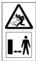
Risk of injury!
Keep other people out of the danger area.
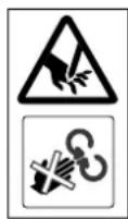
Risk of injury!
Rotating tools! Keep hands and feet away from apertures when the machine is running.
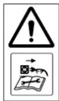
Risk of injury!
Switch off the motor and disconnect the power cable from the machine before working on the cutting tool, before performing maintenance and cleaning work, before checking whether the electric cable is entwined or damaged and before leaving the machine unattended.

Risk of injury!
Rebounding branches and shredding material can pierce hands or fingers.

Wear hearing protection.
Wear safety glasses.

Wear protective gloves.
Do not work in the rain or in a wet environment.

Risk of injury!
Cutting tool runs on. Wait until the cutting tool has come to a standstill.

Risk of injury:
Do not climb onto the machine.

Risk of injury:
Never put your hands or any other part of your body or clothing into the feed chute or ejection chute.
Risk of injury!
Only insert the shredding material on the left side.
text_image
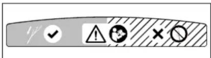
Warning symbol panel with checkmark, warning triangle, minus sign, and donut iconRisk of injury!
When hard material is preselected, insert shredding material on the left side. Note the operating instructions.
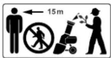
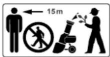
Risk of injury!
Danger of shredding material kickback. Keep other persons out of the danger area. Minimum clearance 15 m.
Preselection of hard material for shredding tree and hedge cuttings as well as thick branch material with side shoots.

Preselection of soft material for shredding organic plant residues such as fruit and vegetable waste, flower cuttings, leaves, etc.
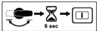
Following actuation of the preselector switch during operation, restarting is only possible after 6 seconds.
6. Standard equipment

Item Designation Qty.
A Basic unit with lower chute 1
B Upper chute 1
C Wheel axle 1
D Wheel carrier 1
E Wheel lock 2
F Bolt, M6 x 55 2
G Hexagon nut 2
H Wheel 2
I Wheel cap 2
J Wheel plug 2
K Roll pin 2
L Self-tapping screw P6 x 50 2
M Discharge flap 1
N Ejection chute extension 1
- Strip 1
P Pin 2
Q Torx screw P5 x 20 3
R Torx screw P5 x 10 2
S Safety screw 3
T Installation tool 1
• Instruction manual 1
7. Preparing the machine for operation

Avoid damage to the machine.
Strictly observe all tightening torques in the following section "Preparing the machine for operation" to avoid damaging the machine.
7.1 Attaching wheel axle and wheels

- Attach the wheel axle (C) with wheel locks (E), bolts (F) and hexagon nuts (G) to the wheel carrier (D) and fasten with installation tool (T) (4 - 6 Nm).
- Push wheel (H) onto mounted wheel axle.
- Push in wheel plug (J) and secure by driving in roll pin (K).
- Fit wheel cap (l).
- Repeat this procedure on the other side.
7.2 Installing the chassis and ejection chute

1 Install the ejection chute extension
- Place the basic unit (A) onto a block of wood with a height of approx. 15-20 cm.
- Engage the hooks (1) of the ejection chute extension (N) into the openings (2) on the rear of the basic unit (A) and turn the extension downwards so that the front part of the basic unit is precisely inserted in the opening of the ejection chute extension.
- Fasten the screws (R) in the lugs of the hooks (1) (1 - 2 Nm).
2 Attach the chassis
- Push the chassis with both wheel carriers (3) as far as they will go into the guides on basic unit (4).
- Push the bent section of wheel carrier (5) into the recess on ejection chute extension (6).
- Insert screws (L) through the openings in wheel carriers (7) and fasten (3 - 4 Nm).
3 Install strip
The bent section of the wheel carrier (5) must be precisely inserted in the recesses on the ejection chute extension (6).
- Position the strip (O) and fasten screws (Q) (1 - 2 Nm).
- Lift machine into upright position.
4 Install the discharge flap
- Attach the discharge flap (M) and press in the pin (P) (use a plastic hammer if necessary). Ensure that the ribs (8) inside the discharge flap on the left and right are all correctly located in the guide groove of the ejection chute extension (9).
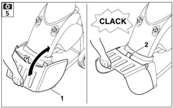
7.3 Opening and closing the discharge flap

Opening the discharge flap:
- For shredding, fold the discharge flap (1) upwards and allow the tab (2) to engage in the ejection chute extension.
Closing the discharge flap:
- For transport or space-saving storage, lift the tab (2) slightly and fold away the discharge flap (1) downwards.
7.4 Attaching the upper chute

The chute can only be installed by a specialist dealer using special tools. STIHL recommends STIHL specialist dealers.
- Place upper chute (B) onto lower chute (1).
- Fold splash guard (2) up as shown and hold in this position.
- Screw in screws (S).
8. Notes on working with the machine
8.1 What material can be processed?
Both soft and hard material can be processed with the garden shredder GHE 355.
Soft material:
Organic plant trimmings such as fruit and vegetable waste, flower cuttings, leaves, etc.
Hard material:
Tree and hedge cuttings and thick branch material with side shoots.

Tree and hedge cuttings should be processed when fresh, as the shredding performance is better with fresh than with dried-out or wet shredding material. Processing dry shredding material increases the risk of kickback. Branch kickback may result in severe injury to the user.

Risk of injury!
When shredding hard material, make sure to set the shredding material correctly on the machine ( 10.7). The setting for the type of shredding material determines the rotational direction of the blades. The user can be seriously injured by shredding material kickback if the setting is incorrect.
8.2 What material cannot be processed?
Stones, glass, bits of metal (wire, nails, etc.) or plastic must not be fed into the garden shredder.
As a general rule:
Any materials that do not belong on the compost heap should not be processed using the garden shredder.
8.3 Maximum branch diameter
Maximum branch diameter GHE 355: 35 mm GHE 375: 40 mm

Caution!
When inserting several thin branches at the same time, the combined diameter of the individual branches must not exceed the maximum branch diameter.
The best shredding performance is achieved with freshly cut tree and hedge clippings.
8.4 Working area for operator

For safety reasons the operator must stay in the working area (grey area) for the entire operating period.
To ensure you are not hit by shredded material that is ejected backwards, you should not stand directly behind the garden shredder but slightly to the side of it (grey hatched area A).
8.5 Correct way to feed the garden shredder


Risk of injury!
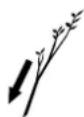
The inclined blade unit can cause branch material to kick back. Branch material kickback may result in serious injury to the user. In order to prevent injuries caused by kickback, the garden shredder must be fed in the correct manner. If the garden shredder is fed from the rear (i.e. the operator is standing in the working area ( 8.4)), the branch material should be inserted at a slight angle and guided along the left-hand chute wall to the blade unit in accordance with the symbol (1).
When feeding, note the maximum branch diameter specified. Thin out any branches with numerous twigs and remove side shoots. The large feed opening is designed to better accommodate branch material with numerous twigs and side shoots.
8.6 Display


The symbol shown on the display is only meaningful when the motor is running. For this reason, switch on the garden shredder before checking the display. ( 10.5)
After the garden shredder has been switched on, the processable shredding material is indicated on the display (1) by the following symbols:
Tree and hedge cuttings as well as thick branch material with side shoots.

Organic plant trimmings such as fruit and vegetable waste, flower cuttings, leaves, etc.
8.7 Correct machine load
The load on the motor or engine of the garden shredder must never cause the speed to drop significantly. Always feed the garden shredder continuously and steadily. If the speed drops when working with the garden shredder, stop feeding the machine in order to relieve the load on the motor or engine.
8.8 Overload protection
If an overload of the motor occurs during operation, the built-in overload protection device automatically switches off the motor.
The garden shredder can be started up again after a cooling period of approx. 10 minutes. Frequent triggering of the overload protection may be attributable to the following causes:
- Unsuitable electric cable (⇒ 10.1)
- Power overload
- Machine overloaded due to excessive quantities of shredding material or blunt blades
8.9 If the cutting unit of the garden shredder is blocked
If the cutting unit of the garden shredder becomes blocked during shredding, immediately switch off the motor and disconnect the power cable. Then remove the feed chute and eliminate the cause of the fault.
9. Safety devices
9.1 Motor restart inhibitor
The machine can only be started via the switch and not by plugging the electric cable into the mains socket.
9.2 Safety interlock
The motor/shredding tool may only be operated when the feed chute has been properly closed. If the right closure screw (machine viewed from the front) becomes loose during operation, the motor is switched off automatically and after a few seconds the shredding tool comes to a standstill.
9.3 Motor run-down brake
The motor run-down brake shortens the run-down time from when the machine is switched off until the blades stop to a few seconds.
9.4 Protective covers
The garden shredder is equipped with protective covers in the feeding and ejection areas. These include the complete feed chute with the upper chute and splash guard, the ejection chute extension and the discharge flap.
The protective covers ensure that a safe distance is maintained from the shredding blades.
10. Operating the machine

Risk of injury!
Carefully read the section entitled "For your safety" ( 4.) and follow all the safety instructions before operating the garden shredder.
- Switch on the motor only as described in the operating instructions. (⇒ 10.5)
10.1 Electrical connection of garden shredders

Risk of injury!
Observe the instructions in section "Warning – dangers caused by electrical current" ( 4.2).

The UK version of the garden shredder has a 10 m electric cable with a special plug. A plug-in fuse is included in this UK plug.
Power supply and operating voltage must correspond (see rating plate).
The power cable must be adequately protected by fuse. ( 17.)
Only electric cables which are no lighter than rubber sheathed cables H07 RN-F DIN/VDE 0282 may be used.
The plug connections must be splash proof. Unsuitable extension cables lead to a loss of power and may result in damage to the motor.
The minimum cross-section of the power cable must be 3 × 1.5 mm^2 for a length of up to 25 m or 3 × 2.5 mm^2 for a length of up to 50 m.
The connectors of the electric cable must be made of rubber or have a rubber coating and conform to the DIN/VDE 0620 standard.
This machine is intended for operation with a power supply having a system impedance of Z_max at the transfer point (house connection) of maximum
0.435 ohms (at 50 Hz).
The user must ensure that the machine is only operated with a power supply which meets this requirement. If necessary, this information can be obtained from the local electric power company.

Your electrician can provide further information on mains connection.
10.2 Connecting the power cable


When choosing a power cable, take account of all the information in the "Electrical connection" section ( 10.1).
GHE 355:
- Connect the power cable connector to the 3-pin mains plug (1) on the machine.
GHE 375:
- Connect the power cable connector to the 5-pin mains plug (2) on the machine.
10.3 Disconnecting the power cable

Disconnect the power cable only by pulling the connector. Never pull the cable.
If the power cable is disconnected during operation of the garden shredder, the machine can only be restarted after a delay of 12 seconds.
10.4 Strain relief
During work, the strain relief prevents any unintentional disconnection of the electric cable and any resulting damage to the mains connection on the machine. For this reason, the electric cable must be fed through the strain relief.
Attaching the cable to the strain relief:
- Connect the power cable. (⇒ 10.2)
- Form a loop in the power cable (1) and guide it through the opening (2).
- Then push the loop over the hook (3) and pull it tight.
Detaching the cable from the strain relief:
- Remove the loop of the power cable from the hook (3).
- Pull the loop of the power cable (1) out of the opening (2).
- Disconnect the power cable if necessary. ( 10.3)
10.5 Switching on the garden shredder


There must be no shredding material in the machine, as it may be expelled when the machine is switched on.
The blade disc locking device must always be tilted back to the stop. (⇒ 11.6)

The garden shredder cannot be switched on if the preselector switch is vertical (centre position).
- Connect the power cable. (⇒ 10.2)
- Press the green button (1) on the switch.
The garden shredder starts up.
10.6 Switching off the garden shredder


Only switch off the motor when there is no longer any shredding material in the machine. Otherwise, the blade disc may become blocked when operation is resumed.
- Press the red button (1) on the switch. The garden shredder motor is switched off and braked automatically.

Risk of injury!
Beware of the work tools running on for several seconds before coming to a standstill after switching off the motor.
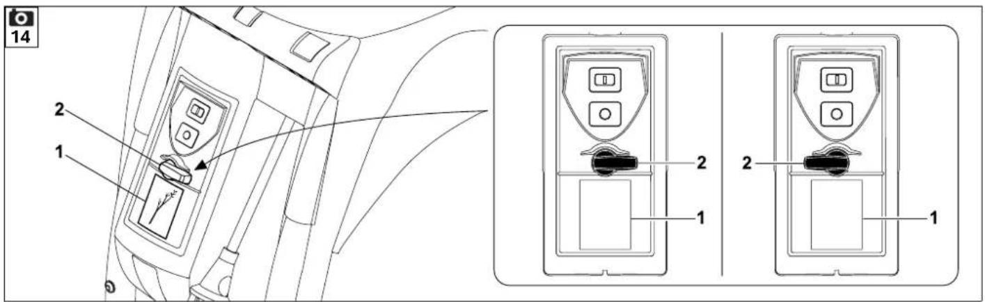
10.7 Preselector switch

Both soft and hard material can be processed with garden shredders GHE 355 and GHE 375. The shredding method can be set by turning the preselector switch.

If the preselector switch is actuated during operation or during the motor run-on time after switching off (motor not yet at standstill), the garden shredder can only be restarted after a delay of 6 seconds for safety reasons. ( 10.5)

The shredding material to be processed is only displayed correctly after the garden shredder has been switched on.

Risk of injury!
The setting for the type of shredding material determines the rotational direction of the blades. The user can be seriously injured by shredding material kickback if the setting is incorrect.
Checking the setting:
- Switch on the garden shredder.
(⇒ 10.5)
The symbol for the processable shredding material currently set appears on display (1). ( 8.6)
Changing the setting:
- Switch off the garden shredder and wait until the cutting unit has come to a standstill. ( 10.6)
- Turn preselector switch (2) through 180°.
- Switch on the garden shredder again.
(⇒ 10.5)
The symbol for the processable shredding material currently set appears on display (1). ( 8.6)
10.8 Shredding
- Push the garden shredder onto firm and level ground and set down safely.
- Wear protective gloves, safety glasses and hearing protection. (⇒ 4.3)
- Open the discharge flap. (→ 7.3)
- Connect the power cable to the garden shredder. (⇒ 10.2)
- Switch on the garden shredder. (⇒ 10.5)
- Wait until the garden shredder has reached its maximum speed (idling speed).
- Check that the shredding material to be processed (hard or soft material) matches the symbol on the display. (⇒ 8.6)
- If the display does not match, change the setting. ( 10.7)
- Feed the garden shredder with shredding material in the correct way. ( 8.5)
- Switch off the garden shredder. (⇒ 10.6)

Risk of injury!
If hard material is shredded with the setting for soft material, strong kickback may occur. Shredding material kickback may result in serious injury to the user.
11. Maintenance

Risk of injury!
In order to prevent inadvertent starting of the motor, always disconnect the power cable prior to all maintenance and cleaning operations, and prior to work on the cutting unit.
Risk of injury!
Always wear protective gloves. ( 4.3)
Do not touch the blades until they have come to a standstill.
If you do not have the necessary expertise or auxiliary equipment, please always contact a specialist dealer.
STIHL recommends that you have maintenance operations and repairs performed exclusively by a STIHL specialist dealer.
STIHL recommends the use of original STIHL spare parts.


11.1 Cleaning the machine
Maintenance interval:
After each use
Clean the machine thoroughly each time it has been used. Care of the machine will protect it against damage and extend its service life.


Never spray water onto motor or engine components, seals, bearing points or
electrical parts such as switches. This would result in expensive repairs.

If you are unable to remove the dirt and accumulated deposits with a brush, a damp cloth or a stick, STIHL recommends the use of a
special cleaner (e.g. STIHL special cleaner).
Do not use aggressive cleaning agents.
Clean the blade discs regularly.
It is only permitted to clean the machine in the position shown.
- Remove the feed chute. (⇒ 11.4)
Remove dirt from the cooling air guide (inlet slots) on the motor housing to ensure that the motor is adequately cooled.
11.2 Service intervals
We recommend that you have your garden shredder serviced once a year by a specialist dealer.
STIHL recommends STIHL specialist dealers.
11.3 Installing the feed chute

Risk of injury!
Always wear protective gloves. ( 4.3)

Before installing the feed chute, make sure that the cutting unit is not locked by the locking device.
- Attach feed chute (1) to the fastening hooks on basic unit (2) and pivot forwards.

- Screw in closure screws (3) and tighten.

Following assembly, check by visual inspection that the feed chute is correctly engaged in the fastening hooks.
11.4 Removing the feed chute


Risk of injury!
Always disconnect the mains plug before removing the closure screws. Always wear protective gloves. ( 4.3)
- Unscrew and remove closure screws (1).
- Pivot feed chute (2) to the rear and remove.
11.5 Blade set service intervals
Maintenance interval:
Before each use
Check the blade set (consisting of blade disc, shredding blades, retaining washer, clamping ring and screw) for wear, firm seating, cracks or other damage.
11.6 Removing the blade set


Risk of injury!
Always wear protective gloves. ( 4.3)

Do not touch the blades until they have come to a standstill.
1 Lock the blade disc
- Remove the feed chute. (⇒ 11.4)
- Turn blade disc (1) to the position shown and fold locking device (2) upwards as far as it goes.
2 Detach the blade set
- Loosen bolt (3) using assembly tool (T) and unscrew completely.
- Remove bolt (3), lock washer (4) and clamping ring (5).
3 Remove the wing blades
- Remove wing blade (6), wing blade (7) and wing blade (8).
4 Remove the blade disc
- Fold back locking device (2).
- Remove blade disc (1).
11.7 Installing the blade set


Risk of injury!
Always wear protective gloves. ( 4.3)

Before attaching the blade set, visually check that the blade disc and all shredding blades are OK and have no notches, cracks or pieces chipped out.

Clean the blade mounting on the machine, the blade disc and the shredding blade before attaching the blade set.

The blade disc including the chipping blade and the three wing blades are equipped with a toothed blade mounting. This prevents incorrect installation of the entire cutting unit, as the blades can only be attached to the blade mounting when in the correct position.
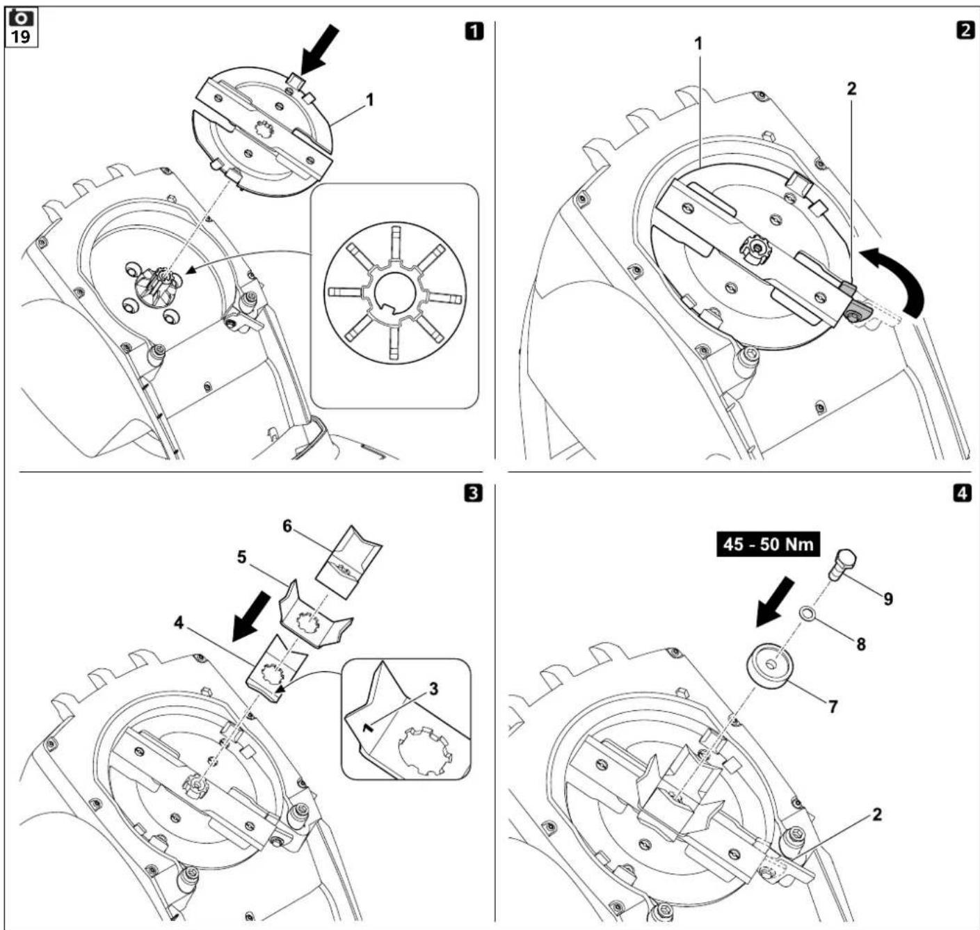
1 Fit the blade disc
- Fit blade disc (1) onto the blade mounting. When doing so, pay attention to the teeth on the blade mounting.
2 Lock the blade set
- Turn blade disc (1) to the position shown and fold locking device (2) upwards as far as it goes.
3 Fit the wing blade

The numbers (3) on the inside of the wing blades refer to their installation sequence.
- Attach wing blade (4), wing blade (5) and wing blade (6).
4 Fasten the blade set
- Attach clamping ring (7) and secure along with retaining washer (8) and bolt (9).
- Tighten bolt (9) using assembly tool (T) (45 - 50 Nm).
- Fold back locking device (2) again.
• Install the feed chute. (⇒ 11.3)
11.8 Wear limits of the blades


The blades must be reversed or replaced before the specified wear limits are reached. STIHL recommends STIHL specialist dealers.
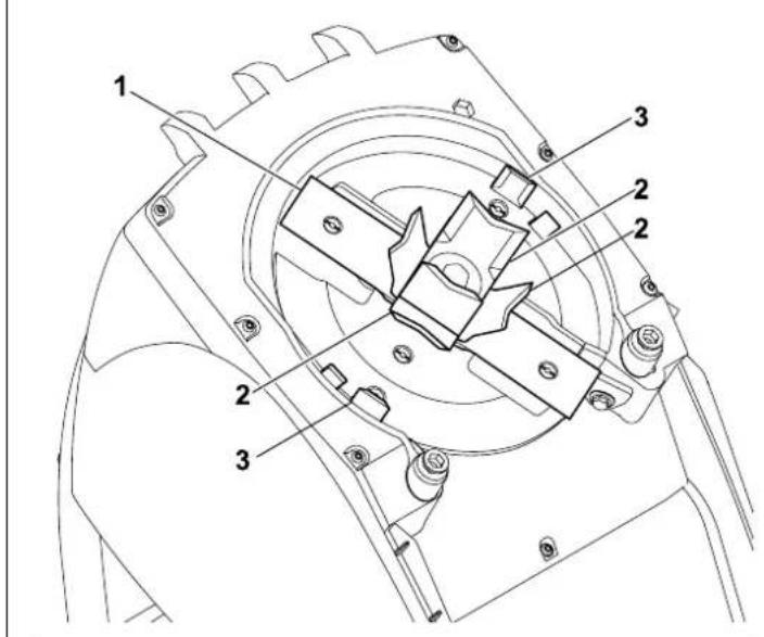
1 Blade overview
- 1 combination blade (1)
- 3 wing blades (2)
- 2 shredding blades (3)
- Remove the blade set. (⇒ 11.6)
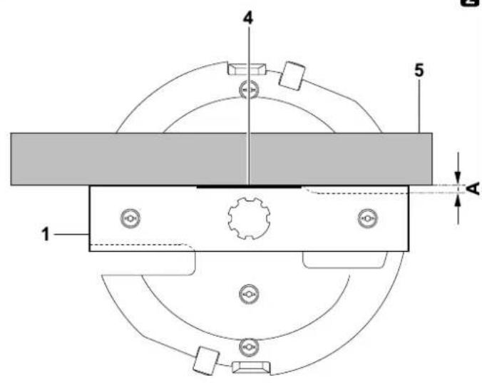
2 Combination blade
- Hold a ruler (5) against the reference edge (4) of the combination blade. The distance (A) between the cutting edge and the ruler indicates the wear.
Maximum wear limit (A) for combination blade (1):
A = 5 mm
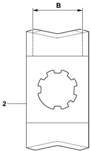
3 Wing blade
The measurement procedure and the value specified are the same for all three wing blades.
Asymmetrical wear may occur at the wing blades due to uneven use of the cutting edges.
- The blade width should be measured at two or three points along the cutting edge. Use the smallest value.
Minimum blade width (B) Wing blade (2):
B = 40 mm
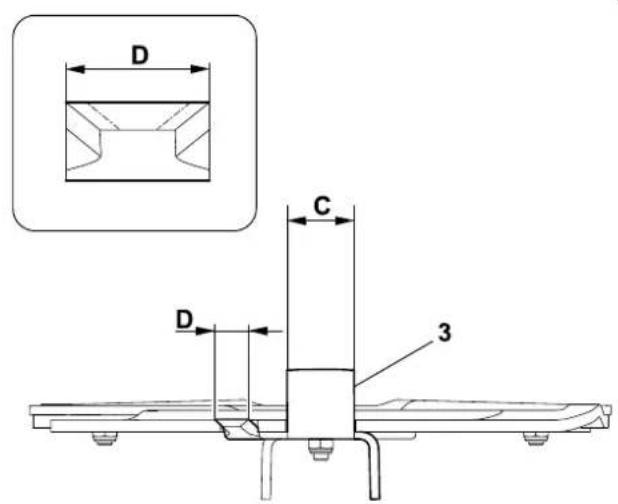
4 Shredding blades
The measurement procedure and the value specified are the same for both shredding blades.
Asymmetrical wear may occur at the shredding blades due to uneven use of the cutting edges.
- The blade widths should be measured at two or three points along the cutting edges. Use the smallest value.
Minimum blade widths (C, D) Shredding blades (3):
C = 23 mm
D = 16 mm
11.9 Sharpening shredding blades

It is recommended that the sharpening of all shredding blades be performed exclusively by a specialist dealer. Blunt and incorrectly ground blades (incorrect sharpening angle, imbalance due to unevenly ground blades, etc.) increase the risk of kickback. Shredding material kickback may result in serious injury to the user. In addition, the performance (intake of the shredding material, stability of the cutting edges, etc.) of the garden shredder may deteriorate.
- Remove the blade set. (⇒ 11.6)
Sharpening angle:
The sharpening angle for all shredding blades is 30^ .
Instructions for sharpening the shredding blades:
The following points must be observed when re-sharpening the shredding blades:
- Cool the blades when sharpening, e.g. with water. The blade must not be allowed to display blue colouring, as this would reduce its cutting quality.
- Sharpen the blade evenly to prevent vibrations due to imbalance.
- Check blades for damage before installing: the blades must be replaced if notches or cracks are visible or if the blades have reached the wear limits.
- Re-sharpen the cutting edges to the specified cutting angle.
- Sharpen the blades against the cutting edge.
11.10 Electric motor and wheels
The electric motor is maintenance-free.
The wheel bearings are maintenance-free.
11.11 Storage and winter break
Store the machine in a dry and locked place that is generally free of dust. Make sure that it is kept out of the reach of children.
Always store the machine in good operational condition.
Keep all nuts, pins and bolts tightly fastened, replace danger signs and warnings on the machine that have become illegible, check the entire machine for wear and damage. Replace all worn or damaged parts.
Any machine faults must be completely remedied prior to storage.
Note the following points when storing the machine for long periods (winter break):
- Clean all external parts of the machine with care.
- Thoroughly lubricate/grease all moving parts.
12. Transport

Risk of injury:
Before transporting, carefully read and observe the section "For your safety", in particular the "Transporting the machine" section. ( 4.4)
Only transport the garden shredder with the chute fitted. Before lifting the machine, note the weight given in the "Technical specifications" section. ( 17.)
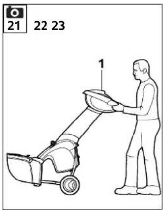
12.1 Pulling or pushing the garden shredder

- Hold the garden shredder at the upper chute (1) and tilt to the rear.
- The garden shredder can be pulled or pushed slowly (walking pace).
12.2 Lifting or carrying the garden shredder


At least two persons are always required to lift and carry the machine.
Wear suitable protective clothing; the lower arms and upper part of the body must be fully covered.
-
- First person: Hold the garden shredder at the handles on the upper chute (1).
-
- Second person: Hold the garden shredder at the bar of the ejection chute extension (2).
- Lift the garden shredder simultaneously.
12.3 Transporting the garden shredder on a load floor
- Secure the machine against slipping using suitable fastening materials. Attach ropes or straps to the wheel carrier (1) or the feed chute (2).
13. Minimising wear and preventing damage
Important information on maintenance and care of the product group
Electric garden shredder (STIHL GHE)
STIHL assumes no liability for material or personal damage caused by the non-observance of information contained in the operating instructions, in particular with regard to safety, operation and maintenance, or which arise through the use of unauthorised attachment or spare parts.
Please always observe the following important information for the prevention of damage or excessive wear to your STIHL machine:
1. Wearing parts
Some parts of the STIHL machine are subject to normal wear even when used properly and must be replaced in due time depending on type and duration of use.
These include:
- B I a d e
- Bladed disc
2. Compliance with the information in this instruction manual
The STIHL machine must be used, maintained and stored with the care described in this instruction manual. Any damage caused by non-compliance with the safety, operating and maintenance instructions is the sole responsibility of the user.
This applies in particular to:
– Inadequately dimensioned power cables (cross section)
- Incorrect electrical connection (voltage)
– Product modifications not approved by STIHL
- Use of tools or accessories which are not approved or suitable for the machine, or are of inferior quality
- Improper use of the product
– Use of the product for sporting or competitive events
- Resultant damage due to continued use of the product with defective components.
3. Maintenance operations
All operations listed in the section "Maintenance" must be performed regularly.
If these maintenance operations cannot be carried out by the user, a specialist dealer must be commissioned to perform them.
STIHL recommends that you have maintenance operations and repairs performed exclusively by a STIHL specialist dealer.
STIHL specialist dealers regularly attend training courses and are provided with technical information.
If these operations are neglected, faults may arise which are the responsibility of the user.
These include:
– Damage to the motor as a result of inadequate cleaning of the cooling air guide (inlet slots, cooling ribs, fan wheel).
- Corrosive and other resultant damage caused by incorrect storage.
– Damage to the machine through the use of inferior-quality spare parts.
– Damage due to untimely or inadequate maintenance or damage due to maintenance or repair work not performed in the workshops of specialist dealers.
14. Standard spare parts
Blade disc assembly
6011 700 5100
Combination blade
6011 702 5100
Wing blade 1
6011 702 0300
Wing blade 2
6011 702 0310
Wing blade 3
6011 702 0320
Set of shredding blades
6011 007 1000
15. Environmental protection
Shredding material should be composted and not disposed of in household waste.
The machine, its packaging and accessories are all produced from recyclable materials and must be disposed of accordingly.
By disposing of materials separately and in an environmentally friendly manner, recyclable waste can be re-used. For this reason, the machine should be disposed of for recycling at the end of its useful life. Improper disposal may be harmful to health and pollute the environment.
15.1 Disposal
Render the machine unusable prior to disposal.
In particular, remove the power cable and electric cable to the motor for this purpose.
Risk of injury from the blades.
Always store an old garden shredder in a safe place prior to scrapping. Make sure that the machine and the blades are kept out of the reach of children.
16. Declaration of conformity
16.1 EU declaration of conformity – STIHL GHE 355.0, GHE 375.0 garden shredder
STIHL Tirol GmbH
Hans Peter Stihl-Strasse 5
6336 Langkampfen
Austria
declares under our sole responsibility that
– design: electric garden shredder
- manufacturer's brand: STIHL
-type: GHE 355.0, GHE 375.0
– power input, GHE 355.0: 2500 W
– power input, GHE 355.0 (GB/CH): 2000 W
– power input, GHE 375.0: 3000 W
- serial number: 6011
complies with the relevant provisions of Directives 2000/14/EC, 2006/42/EC, 2014/30/EU and 2011/65/EU and has been developed and manufactured in accordance with the versions of the following standards valid on the date of manufacture: EN 60335-1, EN 55014-1, EN 55014-2, EN 61000-3-2, EN 61000-3-3 as well as for
- GHE 355.0: EN 50434
– GHE 375.0: EN ISO 12100 with reference to EN 50434.
The measured and guaranteed sound power levels were determined in accordance with Directive 2000/14/EC, Appendix V.
- Measured sound power level: 97.4 dB(A)
– Guaranteed sound power level: 100 dB(A)
The technical documents are stored at STIHL Tirol GmbH.
The year of manufacture and machine number are indicated on the garden shredder.
Langkampfen, 01.02.2022
STIHL Tirol GmbH
p.p.

Matthias Fleischer, Head of Research and Development Division
p.p.

Sven Zimmermann, Head of Quality Department
16.2 UKCA-Declaration of Conformity STIHL GHE 355.0 Garden Shredder
STIHL Tirol GmbH
Hans Peter Stihl-Strasse 5
6336 Langkampfen
Austria
declares under our sole responsibility that
- design: garden shredder
- manufacturer's brand: STIHL
-type: GHE 355.0
– power input: 2000 W - serial number: 6011
complies with the relevant provisions of UK Regulations Noise Emission in the Environment by Equipment for use Outdoors Regulations 2001, Supply of Machinery (Safety) Regulations 2008, Electromagnetic Compatibility Regulations 2016 and The Restriction of the Use of Certain Hazardous Substances in Electrical and Electronic Equipment Regulations 2012 and has been developed and manufactured in accordance with the versions of the following standards valid on the date of manufacture: EN 50434, EN 60335-1, EN 55014-1, EN 55014-2, EN 61000-3-2 and EN 61000-3-3.
The measured and guaranteed sound power levels were determined in accordance with the Noise Emission in the Environment by Equipment for use Outdoors Regulations 2001, Schedule 8.
GHE 355.0
– Measured sound power level: 97.4 dB(A)
– Guaranteed sound power level: 100 dB(A)
The technical documents are stored at STIHL Tirol GmbH.
The year of manufacture and machine number are indicated on the garden shredder.
Langkampfen, 01.02.2022
STIHL Tirol GmbH
p.p.

Matthias Fleischer, Vice President Product Development
p.p.

Sven Zimmermann, Director Quality Management
17. Technical specifications
GHE 355.0 / GHE 375.0:
Serial number 6011
Frequency 50 Hz
Protection class I
Type of protection Splash proof (IPX4)
Operating conditions P40
40 s load time
60 s idle time
Cutting unit drive Permanent
Measurement in accordance with 2000/14/EC / S.I. 2001/1701:
Guaranteed sound power level L_WAd 100 dB(A)
GHE 355.0 / GHE 375.0:
Uncertainty K_WA 2,4 dB(A)
Wheel diameter 250 mm
L/W/H 122/50/141
GHE 355.0:
Electric motor Motor, design (\~)
Manufacturer ATB
Type BSRBF 0.75/2-C
Voltage 230
Power input 2500 W
2000 W (GB)
2000 W (CH)
Fuse* 16 A
10 A (CH)
Maximum branch diameter 35 mm
Nominal motor speed 2750 rpm
Measurement in accordance with EN 50434:
Sound pressure level 94 dB(A) at workplace L_pA
Uncertainty K_pA 3 dB(A)
Weight 30 kg 29 kg (CH) 32 kg (GB)
GHE 375.0:
Motor, design Electric motor (\~3)
Manufacturer ATB
Type BSRF 0.75/2-C
Voltage 400 V\~
Power input 3000 W
Fuse* 10 A
Maximum branch diameter 40 mm
Nominal motor speed 2810 rpm
Measurement in accordance with EN 50434:
Sound pressure level 95 dB(A) at workplace LpA
Uncertainty K_pA 3 dB(A)
Weight 31 kg
\* Attention!
Mains fuses of less than 16 A may frequently trip during start-up of the machine or when it is operating under heavy load.
17.1 REACH
REACH is an EC Directive for the registration, evaluation, authorisation and restriction of chemicals.
Information on compliance with the REACH Directive (EC) No. 1907/2006 is available from www.stihl.com/reach.
18. Troubleshooting
✗ If necessary, contact a specialist dealer; STIHL recommends STIHL specialist dealers.
Fault:
Motor does not start
Possible cause:
– Motor overload protection activated
- N o m a i n s v o l t a g e
– Electric cable, plug, plug connector or switch defective
- Fuse in UK plug damaged (only applies to machines for UK)
- Feed chute not properly closed - safety cut-off switch actuated (safety interlock)
- Blade disc blocked
- Locking device is not reset
Remedy:
- Allow machine to cool down ( 8.8), ( 10.7)
- Check power cable and fuse ✗ (⇒ 10.1)
- Check cable, plug, connector and switch and replace if necessary (by electrician) ✗ (⇒ 10.1)
- Replace fuse ✗ (⇒ 10.1)
- Close feed chute properly and tighten screws ( 11.3)
- Remove feed chute and remove shredder deposits from the housing (Important: disconnect the power cable) ( 11.4)
- Reset locking device (⇒ 11.7)
Fault:
Reduced shredding performance
Possible cause:
- Blunt blades
- Incorrectly ground blades
– Power cable too long - Bent blade disc
Remedy:
- Replace or re-sharpen shredding blades ( 11.9), ( 11.8)
-
Sharpen blades correctly ✗ (⇒ 11.9)
-
Use shorter power cable ( 10.1)
- Check blade disc visually ✗
Fault:
Branch material is not drawn in
Possible cause:
- Incorrect rotational direction of blade disc
- Blunt or incorrectly ground blades
Remedy:
- Change rotational direction of blade disc ( 10.7)
- Regrind combination blade and ensure sharpening angle is exactly correct ✗ (⇔ 11.9)
Fault:
Feed chute cannot be fitted
Possible cause:
- Locking device is not released
Remedy:
- Release locking device (⇒ 11.7)
19. Service schedule
19.1 Handover confirmation
Model:
Serial number:
Date: ____ ____ ____ ____ ____ ____
natural_image
Simple line drawing of a mechanical component with a cylindrical top and rectangular base (no text or symbols)Next service
Date: ____ ____ ____ ____ ____ ____
19.2 Service confirmation
Please hand this instruction manual to your STIHL specialist dealer in the case of maintenance operations. He will confirm the service operations performed in the pre-printed boxes.
Service performed on
Next service date

Chère cliente, cher client,
text_image
Warning symbol panel with checkmark, warning triangle, circular icon, cross, and prohibition symbol2000/14/EC / S.I. 2001/1701:
natural_image
Simple line drawing of a mechanical component with a cylindrical top and rectangular base (no text or symbols)Prochain entretien
Date: ____ ____ ____ ____ ____
text_image
Warning symbol panel with checkmark, warning triangle, cross, and prohibition symbolsGevaar voor letsel!
2 Messenset losmaken
Meting conform 2000/14/EC / S.I. 2001/1701:
Meting conform EN 50434:
GHE 355.0:
| Geluidsdrukniveau | 94 dB(A) |
| op werkplek L_pA | |
| Onzekerheid K_pA | 3 dB(A) |
| Gewicht 30 kg | |
| 29 kg (Ch | |
| 32 kg (GB |
GHE 375.0:
| Motor, type Elektromotor | |
| (~3) | |
| Fabrikant | ATB |
| Type | BSRF 0,75/2-C |
| Spanning | 400 V~ |
| Opvangvermogen | 3000 W |
| Zekering* | 10 A |
| Maximumdiameter van de takken | 40 mm |
| Nominaal toerental elektromotor | 2810 |
| Meting conform EN 50434: | |
| Geluidsdrukniveau op werkplek L_pA | 95 dB(A) |
| Onzekerheid K_pA | 3 dB(A) |
| Gewicht 31 kg | |
\* Opgelet!
natural_image
Simple line drawing of a mechanical component with a cylindrical top and rectangular base (no text or symbols)text_image
Warning symbol panel with checkmark, warning triangle, cross, and prohibition signsMisurazione conforme a 2000/14/EC / S.I. 2001/1701:
natural_image
Simple line drawing of a mechanical component with a cylindrical top and rectangular base (no text or symbols)Prossima revisione
Data: ____ ____ ____ ____ ____
text_image
Warning symbol panel with checkmark, warning sign, globe icon, cross, and no symbolsnatural_image
Simple line drawing of a mechanical component with a cylindrical top and rectangular base (no text or symbols)Próxima revisión
Fecha: ____ ____ ____ ____ ____
text_image
Warning symbol panel with checkmark, warning triangle, globe icon, cross, and donut symbolPerigo de ferimentos!
natural_image
Simple line drawing of a mechanical component with a cylindrical top and rectangular base (no text or symbols)text_image
Warning symbol panel with checkmark, warning triangle, minus sign, and donut iconFare for personskader!
Hvis hardt materiale er forhåndsvalgt, mater du inn kvernematerialet på venstre side. Følg betjeningsmerknadene.
Fare for personskader!
natural_image
Simple line drawing of a mechanical component with a cylindrical top and rectangular base (no text or symbols)Neste service
Dato:
text_image
Warning symbol panel with checkmark, warning sign, globe icon, and cross symbolnatural_image
Simple line drawing of a mechanical component with a cylindrical top and rectangular base (no text or symbols)Nästa service
Datum: ____ ____ ____ ____ ____
19.2 Servicebekräftelse
text_image
Warning symbol panel with checkmark, warning triangle, circle, cross, and prohibition symbolsLoukkaantumisvaara!
natural_image
Simple line drawing of a mechanical component with a cylindrical top and rectangular base (no text or symbols)Seuraava huolto
text_image
Warning symbol panel with checkmark, warning triangle, and cross iconsMåling iht. 2000/14/EC / S.I. 2001/1701:
Garanteret lydeffekt- 100 dB(A) niveau L _WAd
Usikkerhed K_WA 2,4 dB(A)
Hjul-∅ 250 mm
l/b/h 122/50/141
GHE 355.0:
Motor, type Elmotor (\~)
Producent ATB
Type BSRBF 0,75/2-C
Spænding 230
Forbrugseffekt 2500 W
2000 W (GB)
2000 W (CH)
Sikring ^* 16 A
10 A (CH)
Maksimal
grendiameter
Mærkehastighed,
elmotor
Måling iht. EN 50434:
GHE 355.0:
natural_image
Simple line drawing of a mechanical component with a cylindrical top and rectangular base (no text or symbols)Næste service
Dato:
text_image
Warning symbol panel with checkmark, warning triangle, globe icon, and cross symbolnatural_image
Simple line drawing of a mechanical component with a cylindrical top and rectangular base (no text or symbols)Następny przegląd
Data: ____ ____ ____ ____ ____
text_image
Warning symbol panel with checkmark, warning triangle, minus sign, and circle iconsMeritev po 2000/14/EC/S.I. 2001/1701:
Zagotovljena raven 100 dB(A)
Negotovost K_pA 3 dB(A)
Teža 30 kg 29 kg (CH) 32 kg (GB)
GHE 375.0:
Motor, vrsta Elektromotor (\~3)
Proizvajalec ATB
Tip BSRF 0,75/2-C
Napetost 400 V\~
Poraba moči 3000 W
Varovalka* 10 A
Negotovost K_pA 3 dB(A)
Teža 31 kg
* P o z o r !
text_image
Warning symbol panel with checkmark, warning triangle, cross, and donut iconMeranie podl'a 2000/14/EC / S.I. 2001/1701:
natural_image
Simple line drawing of a mechanical component with a cylindrical top and rectangular base (no text or symbols)Đalší servis
Dátum: ____ ____ ____ ____
text_image
Warning symbol panel with checkmark, warning sign, Earth icon, cross, and prohibition symbolsSérülésveszély!
Az 2000/14/EC / S.I. 2001/1701
text_image
Warning symbol panel with checkmark, warning triangle, and cross iconsOpasnost od ozljeda!
Pogon rezne jedinice trajni Mjerenje prema 2000/14/EC / S.I. 2001/1701:
natural_image
Simple line drawing of a mechanical component with a cylindrical top and rectangular base (no text or symbols)Sljedeći servis
Datum: ____ ____ ____ ____ ____
19.2 Potvrda servisa

Prilikom radova na održavanju dajte ove upute za uporabu svom
text_image
Warning symbol panel with checkmark, warning triangle, minus sign, and donut iconNebezpečí úrazu!
natural_image
Simple line drawing of a mechanical component with a cylindrical top and rectangular base (no text or symbols)Dalši servis

text_image
Warning symbol panel with checkmark, warning triangle, circle, cross, and prohibition symbolsSavainošanās risks!
natural_image
Simple line drawing of a mechanical component with a cylindrical top and rectangular base (no text or symbols)Nākamā apkope

text_image
Warning symbol panel with checkmark, warning triangle, minus sign, and donut iconPavojus susižeisti!
Matavimas pagal 2000/14/EC / S.I. 2001/1701:
Garantuojamas 100 dB(A)
garso galios lygis
LwAd
Nuokrypis K_WA 2,4 dB(A)
Rato-∅ 250 mm
text_image
Warning symbol panel with checkmark, warning sign, globe icon, cross, and donut symbolPericol de accidentare!
Măsurători conform 2000/14/CE / S.I. 2001/1701:
Nivel de putere 100 dB(A)
acustică garantat
L_WAd
Incertitudine K_WA 2,4 dB(A)
GHE 355.0 / GHE 375.0:
∅ roată 250 mm
L/I/H 122/50/141
GHE 355.0:
Motor, tip constructiv Motor electric ( )
Producător ATB
Tip BSRBF 0,75/2-C
Tensiune 230 V\~
Putere consumată 2500 W 2000 W (GB) 2000 W (CH)
natural_image
Simple line drawing of a mechanical component with a cylindrical top and rectangular base (no text or symbols)text_image
Warning symbol panel with checkmark, warning triangle, and cross iconsnatural_image
Simple line drawing of a mechanical component with a cylindrical top and rectangular base (no text or symbols)Επόμενη συντήρηση
text_image
Warning symbol panel with checkmark, warning triangle, Earth icon, cross, and prohibition signsnatural_image
Simple line drawing of a mechanical component with a cylindrical top and rectangular base (no text or symbols)Следующий техосмотр

19.2 Подтверждение
text_image
Warning symbol panel with checkmark, warning triangle, Earth icon, cross, and no signnatural_image
Simple line drawing of a mechanical component with a cylindrical top and rectangular base (no text or symbols)text_image
Warning symbol panel with checkmark, warning triangle, and cross iconsVigastusoht!
Mōōtmine 2000/14/EC/ S.I. 2001/1701
kohaselt:
garanteeritud
100 dB(A)
müratase L _WAd
Mõõtemääramatus
2,4 dB(A)
K_WA
Ratta ∅
250 mm
GHE 355.0 / GHE 375.0:
P/L/K 122/50/141
GHE 355.0:
text_image
Warning symbol panel with checkmark, warning triangle, globe, cross, and no symbolsnatural_image
Simple line drawing of a mechanical component with a cylindrical top and rectangular base (no text or symbols)Келесі қызмет
natural_image
Exterior view of a mobile lawn mower (no text or symbols visible)E
INT 1

text_image
Black and white barcode image with vertical lines on both sides0478 201 9914 E