GH 460 C - Plane STIHL - Free user manual and instructions
Find the device manual for free GH 460 C STIHL in PDF.
| Product type | Shredder (planer) |
| Brand | STIHL |
| Model | GH 460 C |
| Dimensions (L/W/H) | 108 / 89 / 137 cm |
| Weight | 75 kg |
| Engine type | 4-stroke petrol engine, OHV, B&S Power Built 3115 series |
| Displacement | 344 cm³ |
| Rated power | 5.8 kW at 2800 rpm |
| Rated speed | 2800 rpm |
| Fuel tank | 2.3 L |
| Maximum branch diameter | 75 mm |
| Cutting unit | MultiCut 450 (two blade discs: soft and hard materials) |
| Wheel diameter | 260 mm |
| Tyre inflation pressure | 1.8 - 2.0 bar |
| Guaranteed sound power level | 108 dB(A) |
| Sound pressure level at workplace | 97 dB(A) |
| Starting | Recoil starter (pull) |
| Safety devices | Safety switch, hopper lock, automatic stop, disc lock |
| Shreddable materials | Soft and hard green waste (branches, hedges, leaves, peelings) |
| Routine maintenance | Cleaning after each use, check levels (oil/fuel), tyre pressure |
| Wear parts | Knives, blade discs, V-belt |
Frequently Asked Questions - GH 460 C STIHL
User questions about GH 460 C STIHL
0 question about this device. Answer the ones you know or ask your own.
Ask a new question about this device
Download the instructions for your Plane in PDF format for free! Find your manual GH 460 C - STIHL and take your electronic device back in hand. On this page are published all the documents necessary for the use of your device. GH 460 C by STIHL.
USER MANUAL GH 460 C STIHL
natural_image
Exterior view of a STIHL industrial power shaver with wheels and control panel (no visible text or symbols)GH 460.0 GH 460.0 C
text_image
Exploded view diagram of a mechanical assembly with labeled parts from A to T and O to U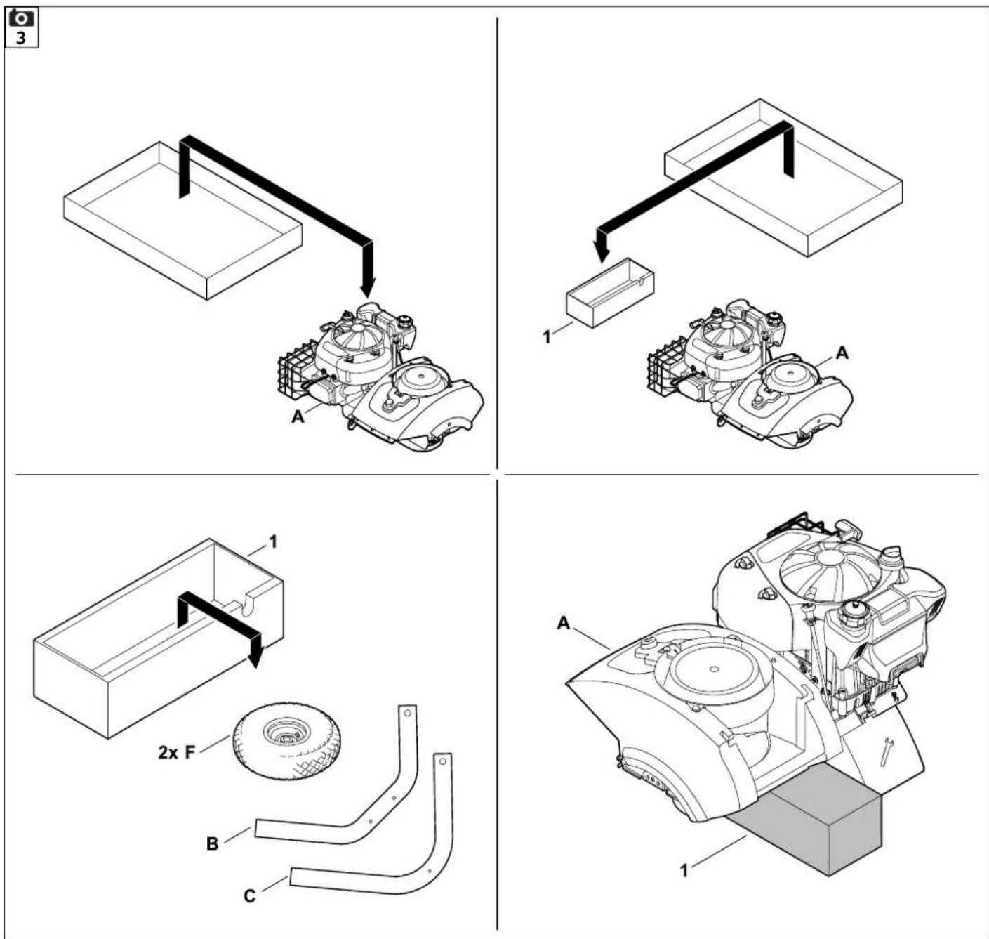
text_image
1 5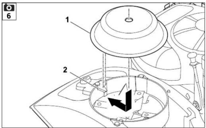
text_image
1 2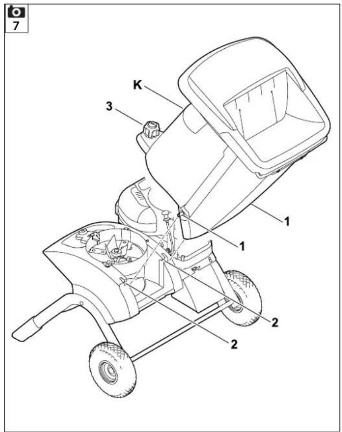
text_image
7 K 3 1 1 2 2 2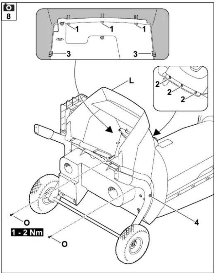
text_image
8 1 1 1 3 3 L 2 2 2 4 O 1 - 2 Nm O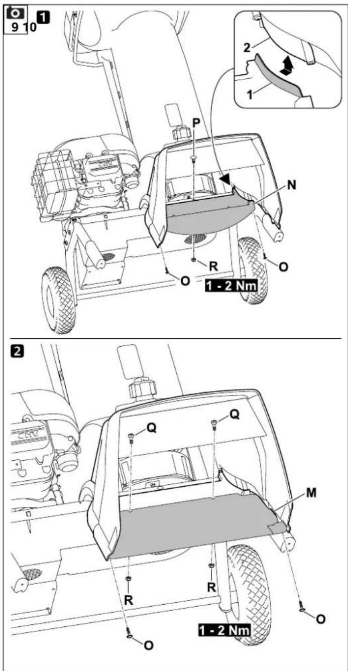
text_image
9 10 1 P N R O O 1 - 2 Nm 2 Q Q M R R O O 1 - 2 Nm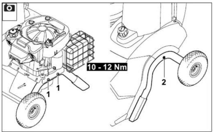
text_image
10 - 12 Nm 1 1 2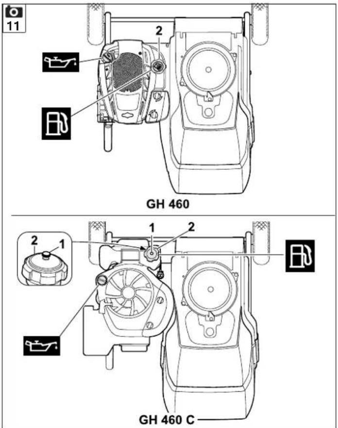
text_image
11 GH 460 2 2 1 2 GH 460 C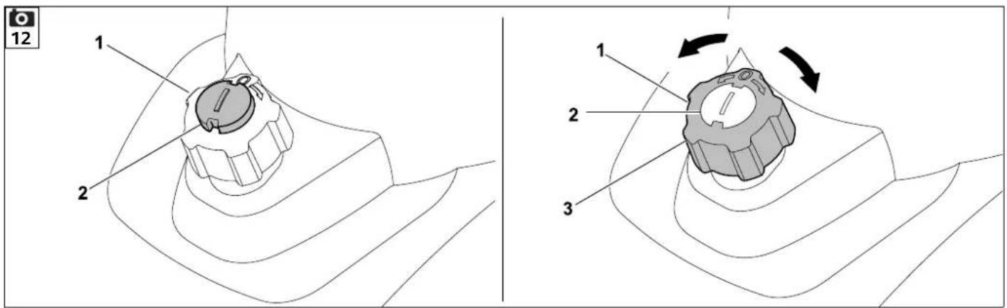
text_image
13 14 1 1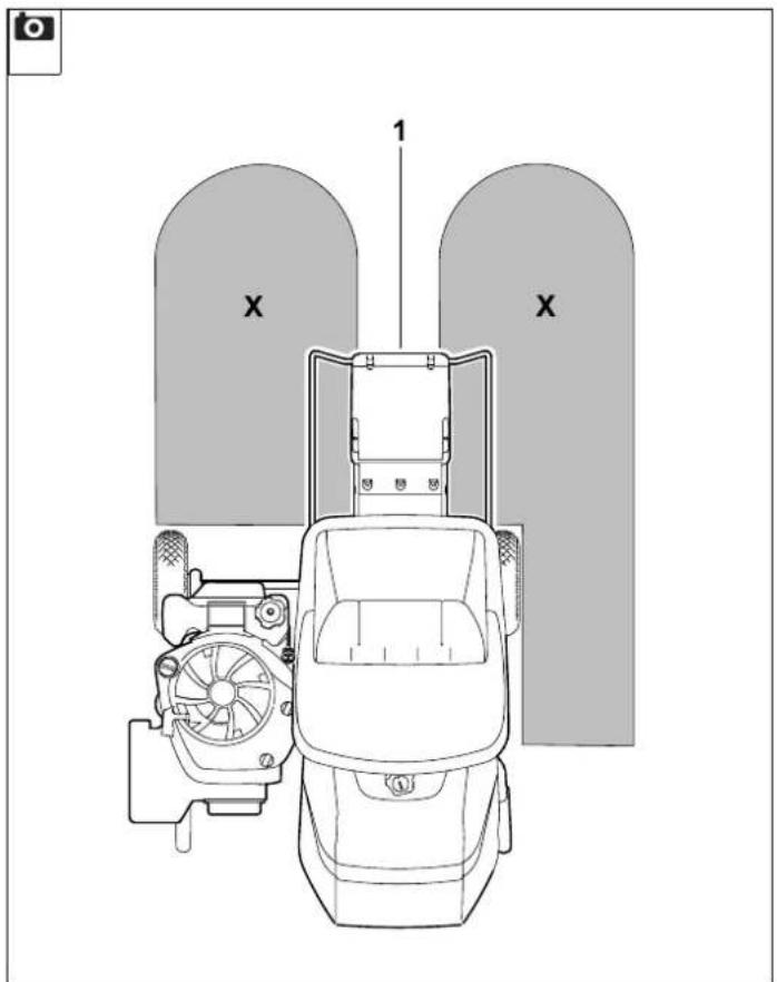
text_image
1 X X0478 216 9906 B
16
text_image
Technical diagram of a mechanical device with labeled parts and annotations in Chinese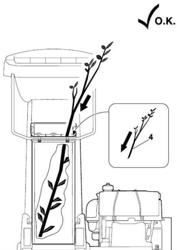
text_image
O.K.17
text_image
3GH 460
text_image
Diagram of a person using a lawn mower with labeled parts 1, 4, and directional arrow indicating motionGH 460
natural_image
Technical line drawing of a mechanical fan assembly with labeled component 3 (no text or symbols beyond label)GH 460 C
text_image
Diagram showing a person using a lawn mower with labeled parts and an inset view of the engine compartment.GH 460 C
18
natural_image
Technical line drawing of a mechanical device with no visible text or symbols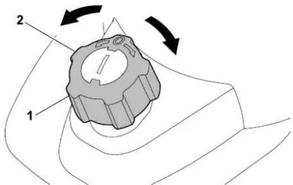
text_image
Technical diagram showing a mechanical component with labeled parts and directional arrows indicating motion or movement.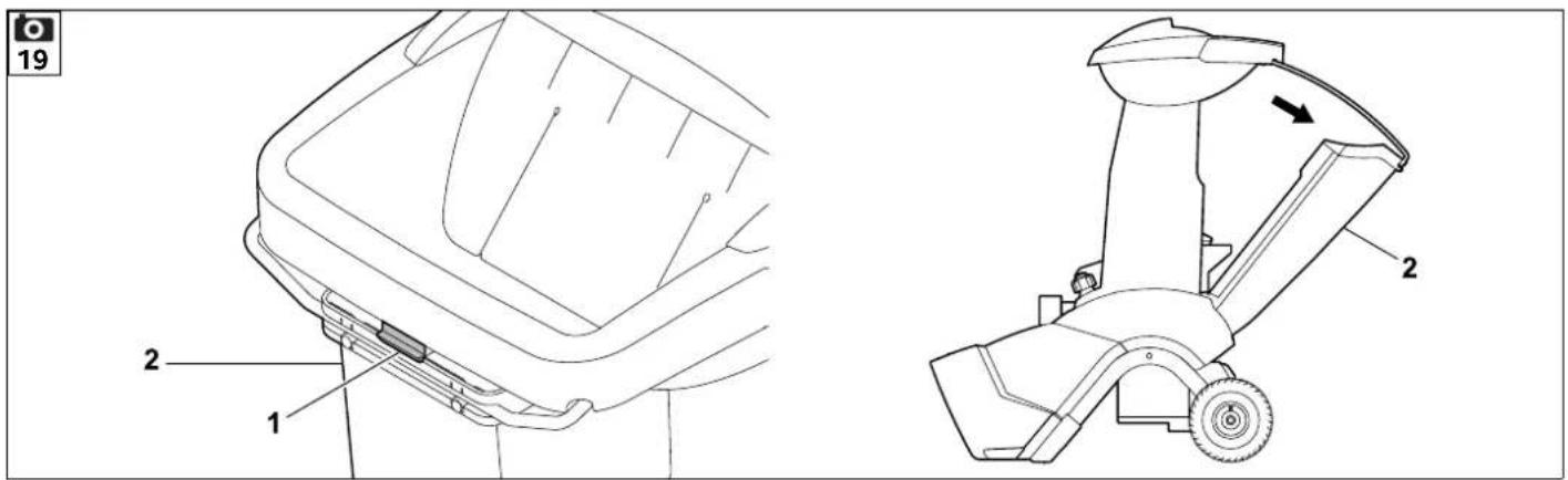
text_image
19 2 1 2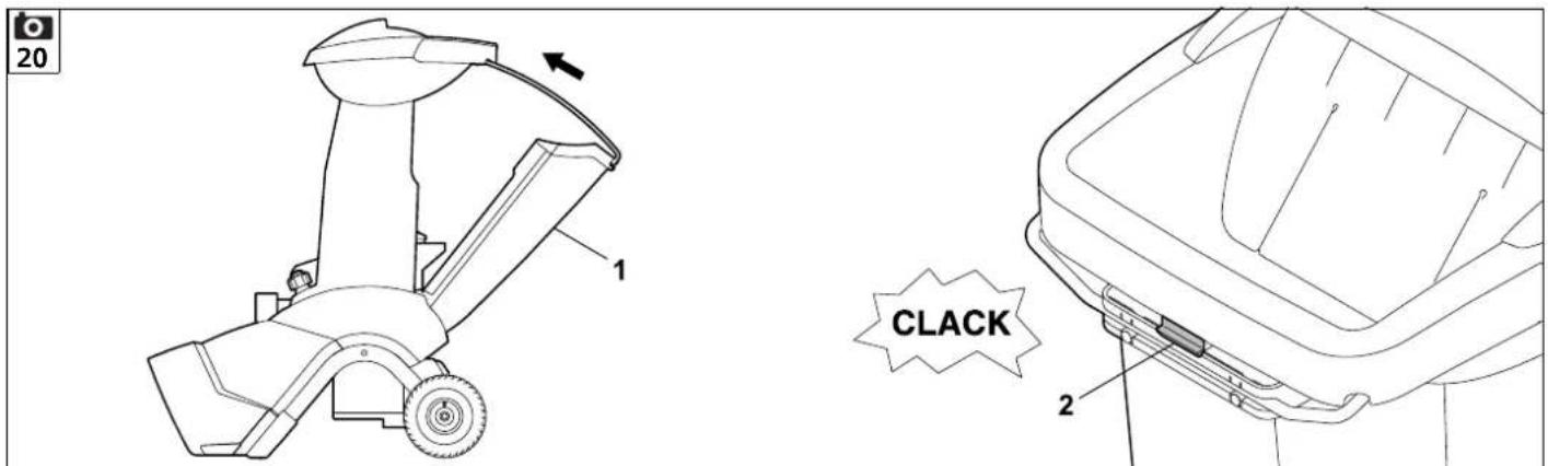
text_image
20 1 CLACK 2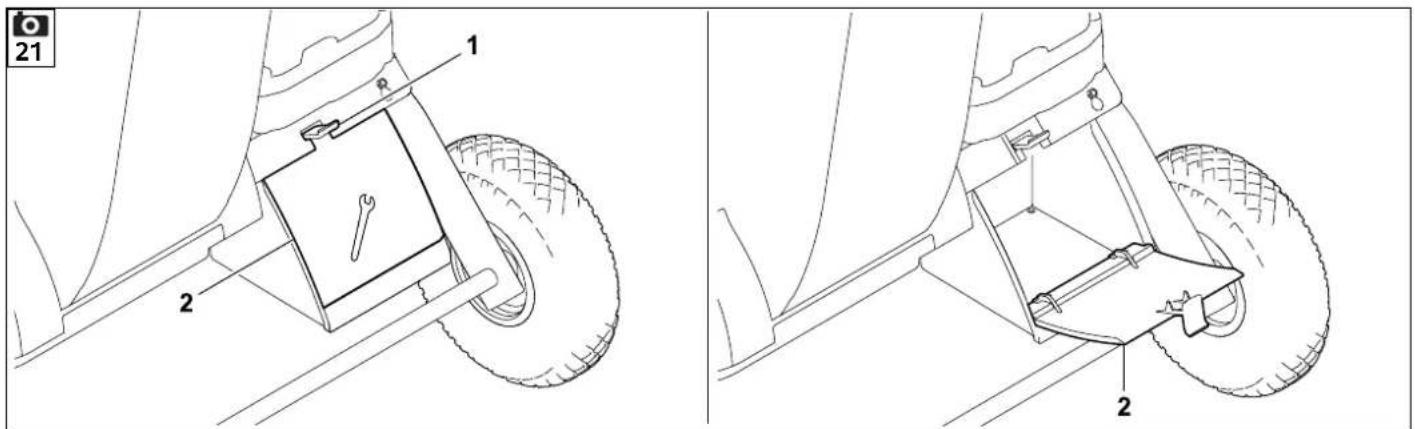
text_image
21 1 2 2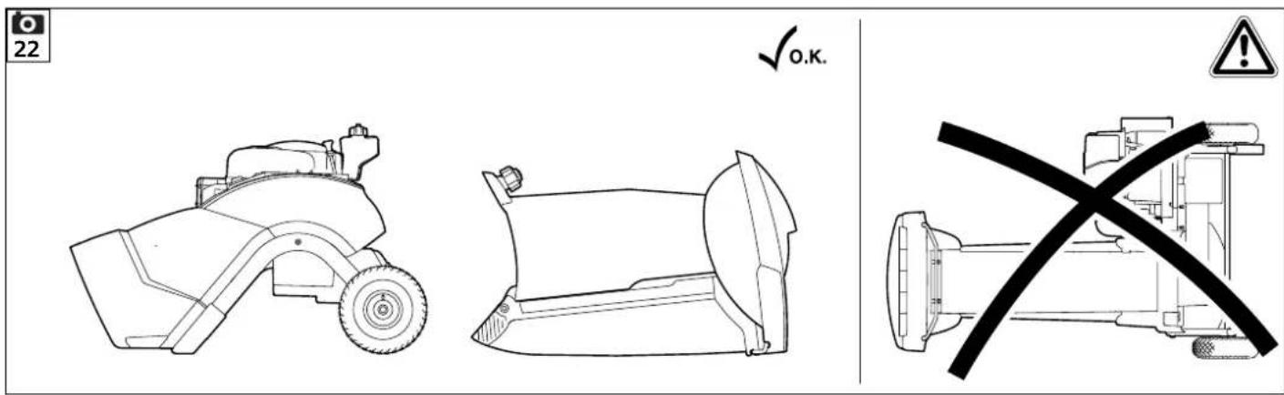
23
text_image
Technical diagram of a mechanical device with labeled parts 1 and 2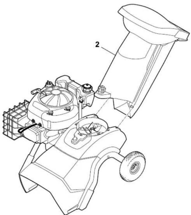
natural_image
Technical line drawing of a lawn mower assembly with labeled parts (no text or symbols present)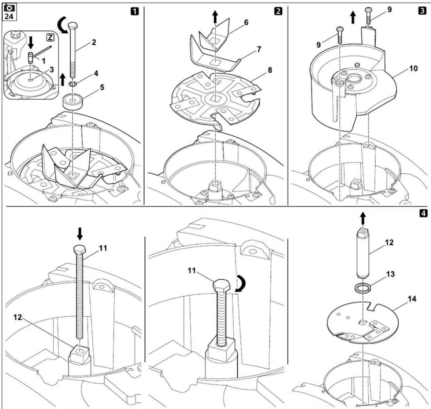
text_image
25 8 33 - 37 Nm A Z 15 16 14 13 12 11 10 36 - 44 Nm 9 6 1 2 1 3 4 5 7 80478 216 9906 B
text_image
26 27 1 2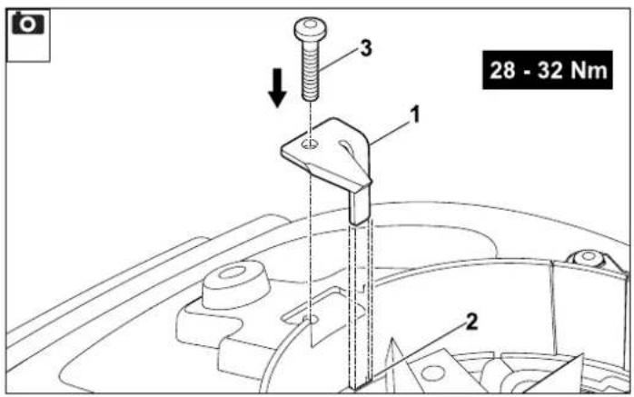
text_image
28 - 32 Nm 1 2 3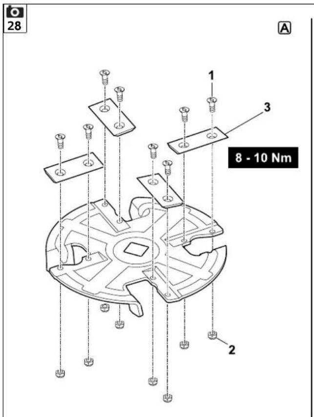
text_image
28 A 1 3 8 - 10 Nm 2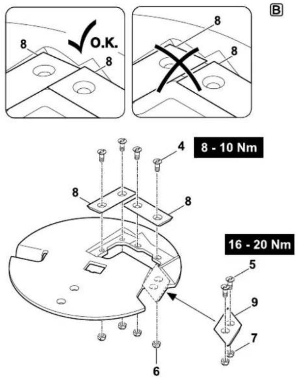
text_image
8 O.K. 8 8 8 8 - 10 Nm 4 8 8 8 5 9 7 6 16 - 20 Nm29
natural_image
Technical line drawing of a mechanical bracket or bracket with a square hole and labeled part '1' (no text or symbols beyond label)2x
natural_image
Simple line drawing of a rectangular plate with two circular holes, labeled with number 2 (no text or symbols on the plate itself)6x
natural_image
Simple line drawing of a flat plate with two circular holes, labeled with number 3 (no text or symbols on the plate itself)1x
natural_image
Technical line drawing of a mechanical bracket or bracket (no text or symbols)1x

text_image
A = 39 mm 1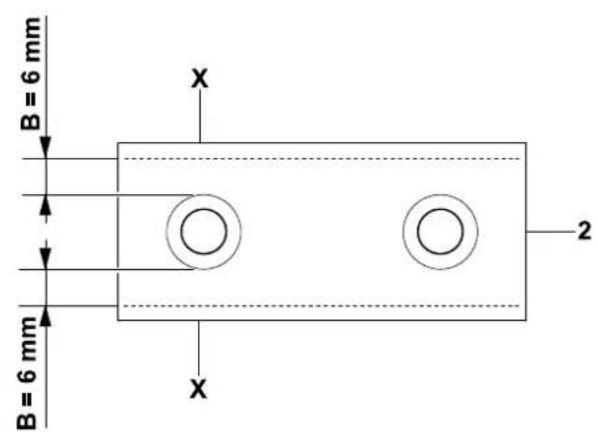
text_image
B = 6 mm B = 6 mm X 2 X3

text_image
C = 7 mm 3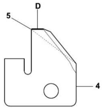
text_image
5 D 45
natural_image
Line drawing of a person pushing a cart with a bucket labeled '1', no text or symbols present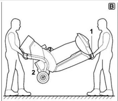
text_image
Technical diagram showing two human figures interacting with a mechanical device, labeled parts 1 and 2.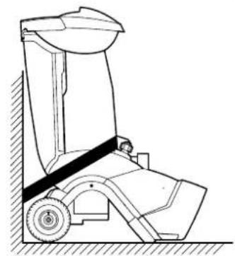
natural_image
Technical line drawing of a mechanical device with wheels and a handle (no text or symbols)C


text_image
2.0 2.0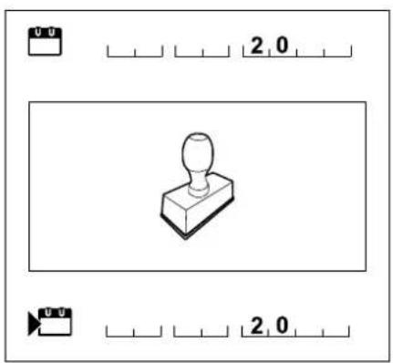
text_image
2.0 2.0
text_image
2.0 2.0
text_image
2.0 2.0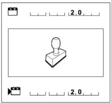
text_image
2,0 2,0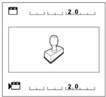
text_image
2.0 2.0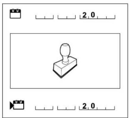
text_image
2.0 2.0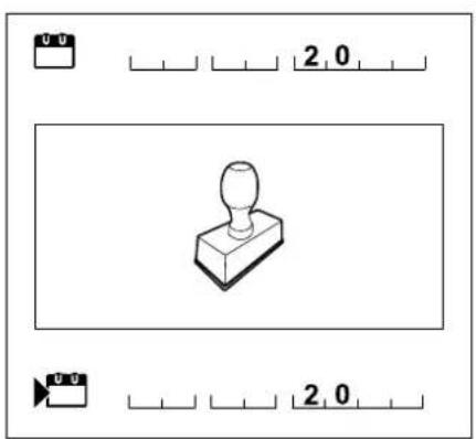
text_image
2.0 2.0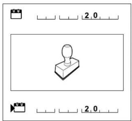
text_image
2.0 2.0S Schraubenschlüssel 1
T Montagewerkzeug 1
GH 460.0 / GH 460.0 C:
Thank you for choosing STIHL. We develop and manufacture our quality products to meet our customers' requirements. The products are designed for reliability even under extreme conditions.
STIHL also stands for premium service quality. Our specialist dealers guarantee competent advice and instruction as well as comprehensive service support.
We thank you for your confidence in us and hope you will enjoy working with your STIHL product.

Dr. Nikolas Stihl
IMPORTANT: READ BEFORE USE AND KEEP IN A SAFE PLACE.
1. Table of contents
Notes on the instruction manual 48
General 48
Instructions for reading the
instruction manual 48
Machine overview 49
For your safety 49
General 49
Refilling the tank – handling petrol 50
Clothing and equipment 50
Transporting the machine 50
Before operation 51
Working with your machine 52
Maintenance and repairs 53
Storage for prolonged periods
without operation 54
Disposal 54
Description of symbols 54
Standard equipment 55
Preparing the machine for operation 55
Unpacking the garden shredder 55
Attaching the chassis 56
Removing the blade cover 56
Installing the blade cover 56
Installing the feed chute ATO 400 56
Installing the ejection chute extension 56
Installing the plates 57
Fuel and engine oil 57
Controls 57
On- / Off switch 57
Choke 58
Notes on working with the machine 58
What material can be processed? 58
What material cannot be processed? 58
Maximum branch diameter 58
Working area for operator 58
Working position of the machine 58
Correct machine load 58
Feeding the garden shredder 59
Safety devices 60
Safety interlock 60
Operating the machine 60
Starting the garden shredder 60
Switching off the garden shredder 60
Folding out the branch guide 61
Folding in the branch guide 61
Tool box 61
Shredding 61
Maintenance 61
Cleaning the machine 61
Removing the feed chute ATO 400 62
Removing the blade discs 62
Installing the blade discs 63
Removing the counter-blade 63
Installing the counter-blade 63
Reversing the blades 64
Sharpening the blades 64
Wear limits of the blades 65
Service interval of the combustion engine 65
Service intervals 65
Wheels 66
Storage and winter break 66
Transport 66
Minimising wear and preventing damage 67
Standard spare parts 68
Environmental protection 68
Disposal 68
EU - Declaration of conformity 68
STIHL GH 460.0, GH 460.0 C
Garden Shredder 68
Technical specifications 69
REACH 69
Troubleshooting 70
Service schedule 71
Handover confirmation 71
Service confirmation 71
2. Notes on the instruction manual
2.1 General
This instruction manual constitutes original manufacturer's instructions in the sense of EC Directive 2006/42/EC.
STIHL is continually striving to further develop its range of products; we therefore reserve the right to make alterations to the form, technical specifications and equipment level of our standard equipment.
For this reason, the information and illustrations in this manual are subject to alterations.
This instruction manual may describe models that are not available in all countries.
This instruction manual is protected by copyright. All rights reserved, especially the right of reproduction, translation and processing using electronic systems.
2.2 Instructions for reading the instruction manual
Illustrations and texts describe specific operating steps.
All symbols which are affixed to the machine are explained in this instruction manual.
Viewing direction:
Viewing direction when left and right are used in the instruction manual: the user is standing behind the machine (working position).
Section reference:
References to relevant sections and subsections for further descriptions are made using arrows. The following example shows a reference to a section: (⇔ 3.)
Designation of text passages:
The instructions described can be identified as in the following examples.
Operating steps which require intervention on the part of the user:
- Release screw (1) using a screwdriver, operate lever (2)...
General lists:
– Use of the product for sporting or competitive events
Texts with added significance:
Text passages with added significance are identified using the symbols described below in order to especially emphasise them in the instruction manual:

Danger
Risk of accident and severe injury to persons. A certain type of behaviour is necessary or must be avoided.

Warning
Risk of injury to persons. A certain type of behaviour prevents possible or probable injuries.

Caution
Minor injuries or material damage can be prevented by a certain type of behaviour.

Note
Information for better use of the machine and in order to avoid possible operating errors.
Texts relating to illustrations:
Illustrations relating to use of the machine can be found in the front of this instruction manual.
The camera symbol serves to link the figures on the illustration pages with the corresponding text passages in the instruction manual.

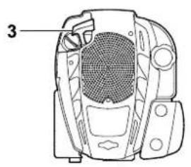
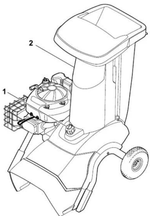
3. Machine overview

1 Feed chute ATO 400
2 Engine
3 On/Off switch
4 Spark plug socket
5 Wheel carrier
6 Ejection chute
7 Wheel
8 Branch guide
9 Transport handle
10 Rating plate with machine number
11 Tool box
12 Branch guide lock
4. For your safety
4.1 General

These safety regulations must be observed when working with the machine.

Read the entire instruction manual before using the machine for the first time. Keep the instruction manual in a safe
place for future reference.
Observe the operating and maintenance instructions contained in the separate engine instruction manual.
These safety precautions are essential for your safety, however the list is not exhaustive. Always use the machine in a reasonable and responsible manner and
be aware that the user is responsible for accidents involving third parties or their property.
Make sure that you are familiar with the controls and use of the machine.
The machine must only be used by persons who have read the instruction manual and are familiar with operation of the machine. The user should seek expert and practical instruction prior to initial operation. The user must receive instruction on safe use of the machine from the vendor or another expert.
During this instruction, the user should be made aware that the utmost care and concentration are required for working with the machine.
Residual risks persist even if you operate this machine according to the instructions.
Make sure that the user is physically, sensorily and mentally capable of operating the machine and working with it. If the user is physically, sensorily or mentally impaired, the machine must only be used under supervision or following instruction by a responsible person.
Make sure that the user is of legal age or being trained under supervision in a profession in accordance with national regulations.

Risk of death from suffocation! Packaging material is not a toy - danger of suffocation! Keep packaging material away from children.
Only give or lend the machine, including any accessories, to persons who are familiar with this model and how to operate it. The instruction manual forms part of the machine and must always be provided to persons borrowing it.
The machine must only be operated by persons who are well rested and in good physical and mental condition. If your health is impaired, you should consult your doctor to determine whether working with the machine is possible. The machine should not be operated after the consumption of alcohol, drugs or medications which impair reactions.
Caution – risk of accident!
STIHL garden shredders are suitable for shredding branch material and plant trimmings. Their use for other purposes is not permitted and may be dangerous or result in damage to the machine.
The garden shredder must not be used (incomplete list):
– for any other materials (e.g. glass, metal).
– for tasks other than those described in this instruction manual.
– for the preparation of foodstuffs (e.g. crushing ice, mashing pulp).
For safety reasons, any modification to the machine, except the proper installation of accessories approved by STIHL, is forbidden and results in voiding of the warranty cover. Information regarding approved accessories can be obtained from your STIHL specialist dealer.
In particular, any tampering with the machine which increases the power output or speed of the engine or motor is forbidden.
It is not permitted to transport objects, animals or persons, particularly children, on the machine.
Particular care is required during use in public green spaces, parks, sports fields, along roads and in agricultural and forestry businesses.
4.2 Refilling the tank – handling petrol

Danger to life!
Petrol is poisonous and extremely inflammable.
Petrol must only be stored in appropriate, tested containers (canisters). Always screw on the fuel tank and canister caps properly and tightly. Defective caps must be replaced for safety reasons.
Never use beverage bottles or similar for disposal or storage of fuels and lubricants. Persons, particularly children, could be tempted to drink out of them.

Keep petrol away from sparks, naked flames, pilot lights, heat sources, and other ignition sources. Do not smoke!
Refill the tank out-of-doors and do not smoke during refilling.
Before refilling the tank, stop the engine and allow it to cool.
GH 460 C: Open the tank ventilation screw before removing the tank cap.
Refilling with petrol must be performed before the engine is started. When the engine is running or is hot, the tank cap must not be removed and the tank must not be refilled with petrol.
Do not overfill the fuel tank!
To give the fuel room to expand, never fill the fuel tank past the lower edge of the filler neck. Observe the additional instructions in the engine instruction manual.


If petrol is spilled, the engine must only be started after the petrol-contaminated area has been cleaned. All attempts at starting must be avoided until the petrol fumes have dispersed (wipe dry).
Any spilt fuel must be wiped up immediately.
Clothing must be changed if it comes into contact with petrol.
GH 460 C: Only close the tank ventilation screw for transport.
Never store the machine with petrol in the tank inside a building. The resulting petrol fumes could come into contact with naked flames or sparks and could be ignited.
If it is necessary to drain the tank, this must be done out of doors.
4.3 Clothing and equipment

Always wear sturdy footwear with high-grip soles when working. Never work barefoot
or, for example, in sandals.

Also always wear sturdy gloves when working and in particular also when performing maintenance operations or
transporting the machine.

Always wear safety glasses and hearing protection when working. Wear them at all times.

Wear suitable, close-fitting clothing when working with the machine, e.g. overalls, but not work coats. Do not wear
scarves, ties, jewellery, clothing with dangling straps or cords or other protruding articles of clothing when working with the machine.
Long hair must be tied up and secured (headscarf, cap, etc.) at all times when operating or performing work on the machine.
4.4 Transporting the machine
Always wear gloves in order to prevent injuries due to sharp-edged and hot components.
Do not transport the machine with the engine running. Switch off the engine, let the blades come to a standstill, close the tank ventilation screw (GH 460 C) and remove the spark plug socket prior to transport.
Only transport the machine once the engine has cooled down and with an empty fuel tank.
Only transport the machine with the feed chute properly fitted and the branch guide folded in.
If it is not possible to transport the machine with the chute fitted, the blade cover must be fitted.
Risk of injury from exposed blades. (⇒ 7.4)
Pay particular attention to the weight of the machine, especially when tilting.
Use suitable loading aids (loading ramps, lifters).
For safety reasons, do not exceed the following angles of inclination when transporting and loading the machine:-
- 10^ (17.6%) angle of lateral inclination,
- 10^ (17.6%) angle of longitudinal inclination,
Secure the machine and other machine parts being transported (e.g. on the load floor using fastening materials (straps, ropes etc.) of an adequate size at the fastening points described in this instruction manual. ( 13.)
Push or pull the machine at walking pace only. Do not tow!
When transporting the machine, always observe regional legislation, especially regarding load security and the transport of objects on load floors.
4.5 Before operation
Make sure that only persons who are familiar with the instruction manual are permitted to use the machine.
Observe the local regulations regarding permitted operating times for gardening power tools with combustion engines or electric motors.
Check the fuel system (particularly visible parts such as e.g. tank, tank cap, hose connections) before operating the machine. In the event of any leaks or damage, do not start the engine – fire hazard!
Have the machine repaired by a specialist dealer prior to operation.
All faulty, worn or damaged parts must be replaced before using the machine. Replace any illegible or damaged danger signs and warnings on the machine. Your
STIHL specialist has a supply of replacement stickers and all the other spare parts.
Before initial operation, it must be ensured
– that the covers and guards are in place and in good condition
– that all fuel-carrying components are fitted to the engine and are in good condition (leak-tight)
– that the tank is in good condition (leak-tight)
– that the housing and cutting tools (blades, blade shaft, blade discs, etc.) are not worn or damaged
– that there is no shredding material in the machine and that the feed chute is empty
– that all screws, bolts, nuts and other fastening elements are in place and properly tightened. Tighten any loose screws, bolts and nuts prior to initial operation (observe tightening torques).
Only use the machine out-of-doors and not close to walls or any other solid objects in order to prevent the risk of injuries and property damage (no escape for the user, broken windows, scratched cars etc.).
The machine must placed in a stable position on firm and level ground.
Do not use the machine on a paved or gravel-covered surfaces, as ejected or thrown-up material could cause injuries.
Before using the machine, always check that it is properly closed. ( 7.5)
Make sure that you are familiar with the On / Off switch so that you can react quickly and correctly in any emergency situation.
When the garden shredder is in the working position, the feed opening must always be completely covered by the splash guard. If this is not the case, the splash guard must be replaced.
Risk of injury:
Only operate the machine when properly assembled. If parts of the machine (e.g. wheels, feet etc.), are missing, the specified safety distances are no longer maintained and the stability of the machine may also be reduced.
Before using the machine, always carry out a visual check to ensure that it is in good operating condition.
"Good operating condition" means that the machine is fully assembled, in particular:
– Upper chute is installed on lower chute
- Branch guide is installed
- Feed chute is installed on the basic machine
– Wheel carrier assembly is installed
- Both wheels are mounted and the tyre pressure complies with the specifications contained in this instruction manual ( 12.12)
- All safety devices (ejection chute, splash guard etc.) must be present and functional
- Both cutting units (blade discs) are installed
– All blades are properly installed
The switch and safety devices installed in the machine must not be removed or bypassed.
Visually inspect both blade discs for damage and deformation; replace if necessary.
4.6 Working with your machine

Never work when animals or persons, particularly children, are in the danger area.
Do not operate the machine in the rain or during thunder storms, particularly when there is a risk of lightning strike.
The risk of accidents is higher if the ground is damp due to increased danger of slipping.
Particular caution should be exercised during working in order to prevent slipping. If possible, avoid using the machine when the ground is damp.
Only work during the day or with good artificial light.
Keep the working area neat and tidy at all times. Remove tripping hazards such as stones, branches, cables etc.
The operator should not stand any higher than the level of the base of the machine.
Exhaust gases:

Danger to life through poisoning! In the case of nausea, headache, impaired vision (e.g. decreasing field of view) hearing disorder, dizziness, decreasing power of concentration, stop working immediately. These symptoms may be caused by excessively high exhaust gas concentrations.

The machine generates poisonous exhaust gases when the engine is running. The gases contain poisonous
carbon monoxide, a colourless and odourless gas, as well as other pollutants. The engine must never be operated in closed or poorly ventilated spaces.
The machine must be positioned so that it is not necessary to work facing the direction of the exhaust gases.
Starting:
Place the machine in a stable and upright position prior to starting. The machine must never be operated in a horizontal position.
Exercise care when starting the machine and observe the instructions contained in the section entitled "Operating the machine" ( 11.). Starting the machine in accordance with these instructions reduces the risk of injury.
Risk of injury!
If the starter rope recoils at speed, the hand and arm will be pulled towards the engine faster than the starter rope can be released. This kickback can result in broken bones, crush injuries and sprains.
Do not stand in front of the discharge opening when starting the engine or switching on the motor. There must be no shredding material in the garden shredder when it is started or switched on. Shredding material may be ejected and lead to injuries.
The machine must not be tilted during start-up.
Do not pull the recoil starter rope if the machine is not properly closed and the blades are exposed.
Risk of injury due to rotating blades!
Working:

Risk of injury!
Never place your hands or feet above, underneath or on rotating parts.
When the machine is running, never put your face or any other part of your body above the feed chute or in front of the ejection opening. Always keep your head and body away from the feed openings.

Never put your hands or any other part of your body or clothing into the feed chute or ejection chute. There is a
considerable risk of injury to eyes, face, fingers, hands etc.
Always maintain your balance and firm footing. Do not stretch forward.
The splash guard must not be tampered with (removed, folded up, jammed into position, damaged etc.) during operation.
The operator must stand in the working area described when feeding the shredder. Stay inside the working area and outside of the ejection zone at all times during operation of the machine. ( 9.4)
Risk of injury:
Shredding material may be ejected back up during operation. Always wear safety glasses and keep your face away from the feed openings.
Never tilt the machine when the engine or motor is running.
If the machine falls over during operation, immediately switch off the engine and detach the spark plug socket.
Make sure that there is no shredding material blocking the ejection chute, as this could result in a poor shredding performance or kickbacks.
When feeding the garden shredder, pay particular attention to ensuring that no foreign objects such as bits of metal, stones, plastic, glass, etc. get into the
shredding chamber as this could result in damage or kickbacks from the feed chute. Remove blockages for the same reason.
Kickbacks can occur when feeding the garden shredder with branch material. Wear gloves.

Beware of the cutting tool running on for several seconds before coming to a standstill.
Switch off the engine, detach the spark plug socket and allow
all rotating tools to come to a complete standstill
– before leaving the machine unattended
– before lifting or carrying the machine
– before transporting the machine
– before removing blockages at the cutting unit, in the feed chute, in the branch guide or in the discharge chute
– before carrying out any work on the blade discs
– before checking or cleaning the machine or before carrying out any other work on it.
Stop the engine,
– before tilting, pushing or pulling the machine
– before unscrewing the closure screw and opening the machine
– before re-filling the tank. Allow the engine to cool down before re-filling the tank.
Fire hazard!
If foreign objects get into the cutting tool or if the machine makes unusual noises or vibrates in an unusual way, stop the engine immediately and allow the machine
to come to rest. Detach the spark plug socket, remove the feed chute and perform the following steps:
- Check the machine, in particular the cutting unit (blade, blade discs, blade shaft, blade fastening screw, clamping ring) for damage and have any necessary repairs carried out by a technician before starting again and working with the machine.
- Check that all parts of the cutting unit are seated securely, retighten the screws if necessary (observe torques).
- Have damaged parts replaced or repaired by a technician; the parts must be of similar quality.
4.7 Maintenance and repairs
Before beginning cleaning, adjustment, repair and maintenance operations:
- Park the machine on firm and level ground
- Stop the engine and allow it to cool down
- Detach the spark plug socket.
Caution – risk of injury!
Keep the spark plug socket away from the spark plug; an inadvertent ignition spark can result in fires or electric shocks.
Inadvertent contact between the spark plug and the spark plug socket can result in unwanted starting of the engine.
Allow the machine to cool down before working on or around the engine, exhaust manifold or muffler in particular.
Temperatures of 80°C and above can be reached. Danger of burns!
Direct contact with engine oil can be dangerous. Engine oil must not be spilled. STIHL recommends leaving the task of topping up engine oil or performing engine oil changes to a STIHL specialist dealer.
Cleaning:
The complete machine must be cleaned thoroughly following use. ( 12.1)
Never use high-pressure cleaners and do not clean the machine under running water (e.g. using a garden hose).
Do not use aggressive cleaning agents. These can damage plastics and metals, impairing the safe operation of your STIHL machine.
In order to prevent fire hazards, keep the area around the air vents, cooling ribs and the area of the exhaust free from e.g. grass, straw, moss, leaves or escaping grease.
Maintenance operations:
Only maintenance operations described in this instruction manual may be carried out. Have all other work performed by a specialist dealer.
If you do not have the necessary expertise or auxiliary equipment, please always contact a specialist dealer.
STIHL recommends that you have maintenance operations and repairs performed exclusively by a STIHL specialist dealer.
STIHL specialist dealers regularly attend training courses and are provided with technical information.
Only use tools, accessories or attachments approved for this machine by STIHL or technically identical parts.
Otherwise, there may be a risk of accidents resulting in personal injury or
damage to the machine. If you have any questions, please consult a specialist dealer.
The characteristics of original STIHL tools, accessories and spare parts are optimally adapted to the machine and the user's requirements. Genuine STIHL spare parts can be recognised by the STIHL spare parts number, by the STIHL lettering and, if present, by the STIHL spare parts symbol. On smaller parts, only the symbol may be present.
For safety reasons, fuel-carrying components (fuel line, fuel cock, fuel tank, tank cap, connections, etc.) must be checked regularly for damage and leaks and replaced by a technician if necessary (STIHL recommends STIHL specialist dealers).
Always keep warning and information stickers clean and readable. Damaged or missing stickers must be replaced by new, original plates from your STIHL specialist dealer. If a component is replaced with a new component, ensure that the new component is provided with the same stickers.
Only perform work on the cutting unit when wearing thick work gloves and exercising extreme care.
Ensure that all nuts, pins and screws, especially all the cutting unit screws, are securely tightened, so that the machine is in a safe operating condition.
Check the entire machine for wear or damage on a regular basis, particularly before extended periods when the machine is not in use (e.g. over winter). For safety reasons, worn or damaged parts must be replaced immediately to ensure that the machine is always in a safe operating condition.
Never alter the basic setting of the engine or run at excessive engine speeds.
Components or guards that are removed for maintenance operations must be properly reinstalled immediately.
4.8 Storage for prolonged periods without operation
Allow the engine to cool before storing the machine in an enclosed space.
Store the machine with empty fuel tank and open tank ventilation screw (GH 460 C) as well as the fuel reserve in a lockable and well-ventilated room.
Ensure that the machine is protected from unauthorised use (e.g. by children).
Never store the machine with petrol in the tank inside a building. The resulting petrol fumes could come into contact with naked flames or sparks and could be ignited.
If the tank has to be emptied (e.g. immobilisation before the winter break), the fuel tank must be emptied out of doors only (empty the tank by running the engine out of doors, for example).
Thoroughly clean the machine before storage (e.g. winter break).
Only store the machine with the spark plug socket disconnected.
Store the machine in good operational condition.
Only store the garden shredder with either the feed chute or the blade cover fitted. Risk of injury due to exposed blades.
4.9 Disposal
Waste products such as used engine oil or fuel, used lubricants, filters, batteries and similar wearing parts can be harmful to people, animals and the environment, and must consequently be disposed of properly.
Consult your recycling centre or your specialist dealer for information on the proper disposal of waste products. STIHL recommends STIHL specialist dealers.
Ensure that old machines are properly disposed of. Render the machine unusable prior to disposal. In order to prevent accidents, remove the ignition lead, empty the fuel tank and drain the engine oil in particular.
5. Description of symbols
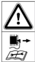
Caution!
Read the instruction manual before initial use.

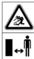
Risk of injury!
Keep other persons out of the danger area.
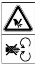
Risk of injury: Risk of injury caused by rotating tools.
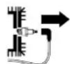
Caution: Detach the spark plug socket before performing any maintenance or cleaning operations.

Wear hearing protection. Wear safety glasses. Wear work gloves.

Risk of injury: Never put your hands or any other part of your body or clothing into the feed chute or ejection chute.

Risk of injury: Do not climb onto the machine.
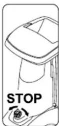
The On / Off switch is located on the front of the machine. Turn the black rotary knob of the On / Off switch to switch off the machine.
6. Standard equipment

Item Designation Qty.
A Basic unit 1
B Right wheel carrier 1
C Left wheel carrier 1
D Foot 2
E Plug 2
F Wheel 2
G Retaining ring 2
H Axle 1
I Torx screw 3 M8x40
J Nut M8 2
K Feed chute ATO 400 1
L Ejection chute extension 1
M Guiding plate 1
N Ejection chute plate 1
O Torx screw 6 P5x20
P Flat head bolt 1 M6x16
Q Torx screw 2 M6x16
R Nut M6 3
S Spanner 1
T Installation tool 1
U Hexagon bolt 1 M14x130
• Instruction manual 1
• Engine instruction manual 1
7. Preparing the machine for operation

Risk of injury:
Carefully read the section entitled "For your safety" ( 4.) and follow all the safety instructions before assembling the garden shredder.
Strictly observe all torques in the "Preparing the machine for operation" ( 7.) section to avoid damaging the machine.

In particular, gloves should be worn and contact with the blades must be avoided.

Avoid damage to the machine. Place cardboard underneath the machine to protect it from being scratched.
7.1 Unpacking the garden shredder


Risk of injury:
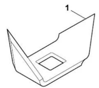
Lift the machine only with the help of a second person. Make sure that the cardboard insert (1) is not damaged.
- Open the packaging.
Installation position:
- Remove the basic unit (A) from the packaging with the help of a second person and place it on the ground.
-
Remove the cardboard insert (1) and place it on the ground. Remove the wheels (F) and wheel carriers (B, C).
-
Place the cardboard insert (1) on the ground with the closed side facing upwards.
- Lift the basic unit (A) with the help of a second person and place it on the cardboard insert as shown.
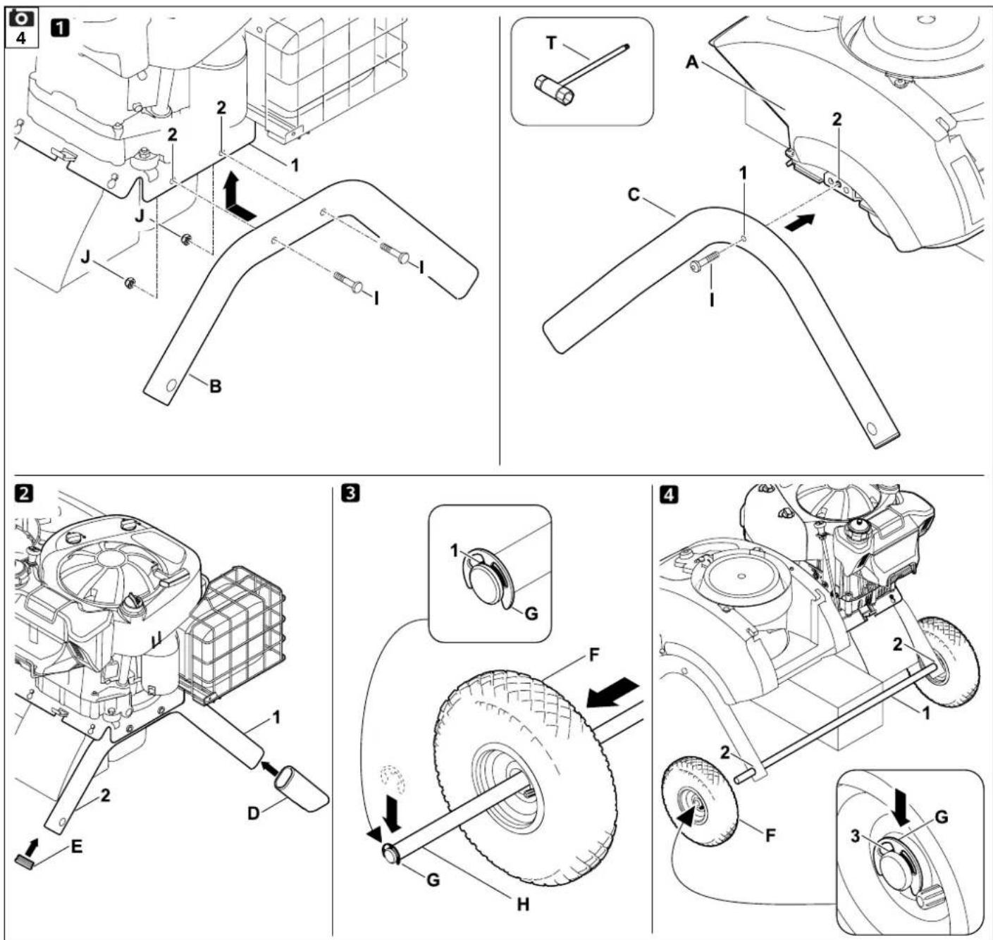
7.2 Attaching the chassis


Risk of injury:
The blade cover must be attached to prevent any injuries from the sharp blades. ( 7.4)
1 Install right and left wheel carrier:
- Raise the basic unit into the assembly position. ( 7.1)

Attach both wheel carriers to the basic unit in such a way that the bores for the axle are located at the rear (on the tool box side).
Attaching the right wheel carrier:
- Position right wheel carrier (B) on the inside of angled support plate (1). The bores in the wheel carrier must align with the bores in the support plate.
- Position a nut (J) on the inside. Insert screw (I) through the bores (2) in the support plate and in the wheel carrier and screw into the nut (J) but do not tighten.
- Repeat this procedure at the second bore in the right wheel carrier.
Attaching the left wheel carrier:
- Hold the left wheel carrier (C) with the bore (1) at the centre bore (2) on the left side of the basic unit (A).
- Screw in the screw (I) using the installation tool (T), but do not tighten.
2 Install the foot and plug:
- Push the foot (D) as far as possible onto right wheel carrier (1) as shown. The foot engages in the right wheel carrier.
- Repeat this procedure on the left wheel carrier.

Risk of injury:
After installing, check that both feet are seated securely.
- Carefully drive plug (E) into right wheel carrier (2) as far as possible.
- Repeat this procedure on the left wheel carrier.
3Mount the wheel on the axle:

Mount the wheels so that the valves are located on the outside.
- Push the retaining ring (G) as far as possible into the groove (1) in axle (H).
- Push the wheel (F) onto the axle (H).

In order to prevent the wheel from becoming loose when installing, ensure that retaining ring (G) engages correctly in the groove (1) in axle (H).
4 Install the axle and wheel:
- Push the axle, with pre-installed wheel (1) through the bores (2) in the wheel carrier.
- Push the left wheel (F) onto the axle (1).
- Push the retaining ring (G) as far as possible into the groove in the axle (3).
- Remove the basic unit from the cardboard insert.
- Raise the basic unit into the working position.
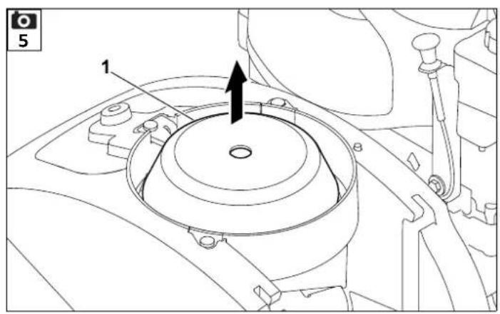
7.3 Removing the blade cover
- Hold the blade cover (1) at the bore and lift off the cover.

7.4 Installing the blade cover
- Insert the blade cover (1) under the counter-blade (2).
Then press down the blade cover (1). When properly installed, the blade cover (1) must lie against the blade disc correctly.

7.5 Installing the feed chute ATO 400
- Remove the blade cover. (⇒ 7.3)
- Insert the two fastening hooks (1) on feed chute ATO 400 (K) into the two openings in the basic unit (2).
- Tilt the feed chute ATO 400 (K) forwards to the stop.
- Screw in the On / Off switch (3) and tighten.

Following assembly, check that the feed chute ATO 400 is correctly engaged in both openings in the basic unit.

7.6 Installing the ejection chute extension
- Carefully set the machine on its back.


Place cardboard underneath in order to prevent damage.
Installing the ejection chute extension
- Attach the ejection chute extension (L), engage the hooks (1) in the apertures on the housing (2) from above, turn downwards and push on the retainers (3) at the side.
- Screw in the screws (O) and tighten to 1 - 2 N m.

In order to facilitate installation of the guiding plate, we recommend loosening the left wheel carrier slightly.
- Loosen the screw (4) at the left wheel carrier by approx. 5 turns.
7.7 Installing the plates

1 Install the guiding plate
- Insert the guiding plate (N). Ensure that the guides on the guiding plate (1) are correctly located in the guides of the ejection chute extension (2).
• Fit screw (P) and tighten with nut (R). - Screw in the screws (O) and tighten to 1 - 2 N m.
2 Install the ejection chute plate
- Insert the ejection chute plate (M).
- Screw in the screws (O) and tighten to 1 - 2 N m.
- Fit screws (Q) and tighten with nuts (R). Any slight tensions occurring in the ejection chute can be compensated by readjusting the screws.
Tightening the screws of the wheel carrier mounting

- Stand the machine up and check for correct seating of all attached parts.
- Tighten screws (1, 2) of the wheel carrier mounting to 10 - 12 Nm.

After tightening screws, check that both wheel carriers are securely seated.
7.8 Fuel and engine oil


Top up engine oil before initial start (⇒ engine instruction manual)!
Engine oil
Please consult the engine instruction manual for the type of engine oil to be used and the oil capacity. Check the oil filling level at regular intervals ( see engine instruction manual). Avoid exceeding or falling below the correct oil level.
Fuel
Recommendation: Fresh good quality fuel, normal unleaded petrol ( engine instruction manual)! Use a funnel when filling the tank with fuel (not included in standard equipment). Note the warnings in the section "For your safety". ( 4.)
Filling the fuel tank
- GH 460 C:
Open the tank ventilation screw (1).
• Unscrew the tank cap (2). - Fill the fuel tank (use a funnel).
- Replace the tank cap (2).

GH 460 C: Open the tank ventilation screw (1) prior to initial operation of the engine.
8. Controls
8.1 On-/Off switch

The On- / Off (1) switch is a multifunction switch with the following functions:
Safety switch:
The On-/Off switch (1) functions as a safety switch. ( 10.)
Function enable switch during the starting procedure:
The On-/Off switch (1) serves as the main switch when starting the engine. The engine cannot be started if the On-/Off switch (1) is not operated. ( 11.1)
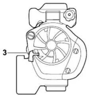
Switching off:
When the On-/Off switch (1) is released by turning, the engine switches off and the blade discs come to a standstill within a few seconds (see Releasing the On-/Off switch). ( 11.2)
Fastening screw for the feed chute:
The feed chute ATO 400 is detached by unscrewing (anti-clockwise) the On- / Off switch (1). The feed chute ATO 400 is secured to the basic unit by screwing in (clockwise) the On- / Off switch (1).
Operating the On-/Off switch:
- Press in the green button (2) (symbol I) as far as it will go. The green button locks into place and remains pressed down. The garden shredder can be started. (⇒ 11.1)
Releasing the On-/Off switch:
- Turn the black knob (3) (red symbol O) at the On-/Off switch (1) (in either direction). The green button (2) is released and the engine stops. The blade discs come to a standstill within a few seconds.
8.2 Choke

GH 460:
The model GH 460 has an auto-choke that does not need to be operated manually.
GH 460 C:
When the choke knob (1) is operated, the air/fuel mixture changes to enable a cold engine to be started more easily.

It should be remembered that the engine can cool down rapidly in very cold weather.
If the choke is not deactivated after the starting procedure, more smoke will be produced as a result of the altered air/fuel mixture.
Subsequently, the engine will stall (engine will be flooded).
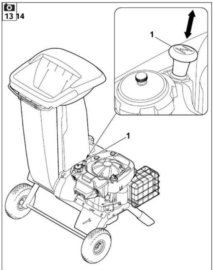
Operating the choke:
- Pull out the choke knob (1). This operates the choke and the engine can be started.
Deactivating the choke:
- Once the engine is running after the starting procedure, the choke must be deactivated immediately by pressing in the choke knob (1) fully.
9. Notes on working with the machine
9.1 What material can be processed?
Both soft and hard material can be processed with the garden shredder.
Soft material:
Organic plant trimmings such as fruit and vegetable waste, flower cuttings, leaves etc.
- Shredding soft material. (⇒ 11.6)
Hard material:
Tree and hedge cuttings and thick branch material with side shoots.
- Shredding hard material. ( 11.6)

Tree and hedge cuttings should be processed when fresh, as the shredding performance is better with fresh than with dried-out or wet material.
9.2 What material cannot be processed?
Stones, glass, bits of metal (wire, nails, etc.) or plastic must not be fed into the garden shredder.
As a general rule:
Any materials that do not belong on the compost heap should not be processed using the garden shredder.
9.3 Maximum branch diameter
The data relates to freshly cut branch material:
Maximum branch diameter:
GH 460: 60 mm; GH 460 C: 75 mm

The size of the feed opening of the branch guide serves only to better accommodate branch material with side shoots and does not indicate the maximum permitted diameter of the shredding material.
9.4 Working area for operator

- For safety reasons, the operator must stay within the working area (grey area X) for the entire operating period.

Risk of injury:
To ensure you are not hit by shredding material that is ejected backwards when processing hard material (branch guide (1) folded out), you should stand slightly to one side of the garden shredder (see grey area X) and not directly behind it.
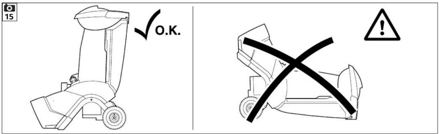
9.5 Working position of the machine

The garden shredder must only be operated in an upright position. The garden shredder must be stood on its two wheels and on the two wheel carriers as shown for the entire period of operation.
9.6 Correct machine load
The load on the motor or engine of the garden shredder must never cause the speed to drop significantly. Always feed the garden shredder continuously and steadily. If the speed drops when working
with the garden shredder, stop feeding the machine in order to relieve the load on the motor or engine.
9.7 Feeding the garden shredder


Risk of injury!
Carefully read the section entitled "For your safety" ( 4.), subsection "Working with your machine" ( 4.6) in particular, and follow all the safety instructions before feeding the garden shredder. It is only permitted for one person to feed the garden shredder.

Risk of injury!
Never reach into the feed opening.

Observe the correct engine load. (⇒ 9.6)
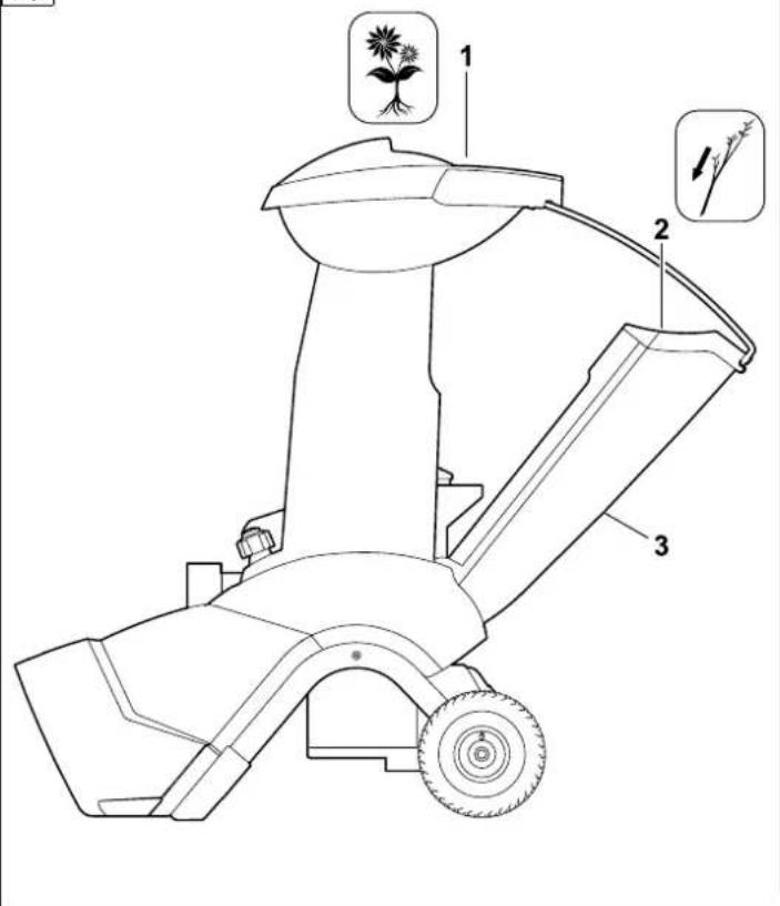
Do not feed material into the two feed openings (1, 2) on the garden shredder at the same time. Danger of blocking.
Soft material:
- Before feeding the garden shredder, note the working area. ( 9.4)
- Start the garden shredder. (⇒ 11.1)
- Throw organic plant trimmings such as fruit and vegetable waste, flower cuttings, leaves, thin branches etc. into the feed opening (1) for soft material.


The feed opening (1) is only for feeding with soft material or with thin branches (up to approx. 10 mm in diameter) with numerous side shoots and twigs. The branch guide (3) should be folded in when feeding soft material into the shredder. ( 11.4)
Damp or wet soft material will cause blockages in the machine more quickly. For this reason, feed the garden shredder more slowly and pay particular attention to the engine speed. When feeding soft material into the machine, make sure that the engine hood is not covered with shredding material. Risk of engine overheating due to covered cooling slots.

Always keep the engine clean.
Hard material:
- Before feeding the garden shredder, note the working area. ( 9.4)
- Fold out the branch guide (3). (⇒ 11.3)
- Observe the maximum branch diameter. ( 9.3)
- Start the garden shredder. (⇒ 11.1)

Risk of injury:
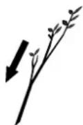
In order to prevent injuries caused by kickback, the garden shredder must be fed with hard material in the correct manner. If the garden shredder is fed from the rear (i.e. the operator is standing in the working area ( 9.4), the branch material should be inserted at a slight angle and guided along the left-hand chute wall to the blade unit in accordance with the symbol (4). When feeding, note the maximum branch diameter. ( 9.3) The large feed opening (2) is designed to better accommodate branches with numerous side shoots and twigs.

Cut up thick branches and branches with numerous side shoots (note the maximum branch thickness) beforehand using loppers. Throw thin pruning material (up to approx. 10 mm in diameter) into the feed opening (1) for soft material.
- Feed tree and hedge cuttings and branch material slowly into the feed opening (2) of the folded-out branch guide (3). The hard material is automatically drawn in by the machine. You should support and guide longer branches with your hand when shredding.
10. Safety devices
10.1 Safety interlock
The garden shredder may only be operated when the feed chute ATO 400 is properly closed. If the On-/Off switch is released during operation, the motor or the engine is switched off automatically and the shredding tool comes to a standstill within a few seconds. In addition, the two blade discs are mechanically locked automatically if the feed chute ATO 400 is removed.
11. Operating the machine
11.1 Starting the garden shredder


Risk of injury!
Carefully read the section "For your safety" ( 4.) and follow all the safety instructions before operating the garden shredder. Before use, check that the feed chute ATO 400 is properly closed and the On/Off switch (1) has been tightened hand-tight.
Risk of injury due to engine kickback!
On model GH 460 C, clasp the handle (3) of the recoil starter rope (4) firmly in one hand and hold. The recoil starter rope (4) must be pulled in one swift tug.
Check the tyre pressure before each use. ( 12.12)
The On/Off switch (1) must be operated before starting the engine. If the On/Off switch is not operated, the engine will not start (safety device). ( 8.1)
- Operate the On/Off switch (1). ( 8.1)
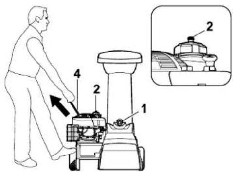
GH 460 C:
- Open the tank ventilation screw (2).
- Operate the choke when the engine is cold. ( 8.2)
- Stand at the side of the machine (note the working area ( 9.4) ).
GH 460:
- Stand behind the machine (note the working area ( 9.4)) and press against the axle with one foot.
GH 460, GH 460 C
- Clasp the handle (3) of the recoil starter rope (4) firmly in one hand and hold.
- Slowly pull out the recoil starter rope (4) to the point of compression resistance. Then pull vigorously and quickly to arm's length. Slowly return the recoil starter rope (4) so that it is rolled up again. Repeat the procedure until the engine starts.
GH 460 C
- When the engine is running, deactivate the choke again immediately. ( 8.2)
11.2 Switching off the garden shredder


Risk of injury!
Do not step into the ejection area when switching off!
Do not stand on the engine side and bend over the machine when switching off the garden shredder – Danger of burns due to hot engine components.
Beware of the work tools running on for several seconds before coming to a standstill after switching off the engine.

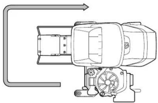
Note the pictogram on the front of the upper chute.
Only switch off the engine when there is no further shredding material in the machine, otherwise this could cause a blockage at one of the two blade discs when is used next.
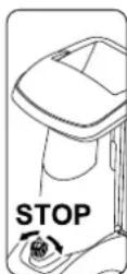
- Note the direction indicated in the illustration and the marked location for switching off.
- The garden shredder is switched off by turning the black knob (1) (symbol O) at the On-/Off switch (2) (in either direction). The garden shredder engine stops.
The engine and the blade discs come to a standstill within a few seconds.
11.3 Folding out the branch guide


Risk of injury:
For safety reasons, only fold the branch guide (2) in and out when the machine is switched off.
- Press branch guide lock (1) upwards and hold.
- With your other hand, move the branch guide (2) slowly to the rear (away from the machine).
- Release the branch guide lock (1) again and fold out the branch guide (2) as far as possible.
11.4 Folding in the branch guide


Risk of injury:
For safety reasons, only fold the branch guide (1) in and out when the machine is switched off.
Danger of pinching:
When closing the branch guide, make sure that your fingers are not pinched between the branch guide and the feed chute.
- Slowly fold in the branch guide (1) as far as possible (press against the machine) until it latches into the branch guide lock (2).
11.5 Tool box

To open the tool box:
- Press the tab (1) downwards and hold.
- Fold down the tool box lid (2).
Closing the tool box:
- Push the tool box lid (2) until the tab latches into place.
11.6 Shredding
- Push the garden shredder onto firm and level ground and set down safely.
- Put on thick gloves, safety glasses and hearing protection.
- Check the oil level, fuel and tyre pressure. (⇒ 7.8), (⇒ 12.12)
- For hard material (e.g. tree- and hedge cuttings) fold out the branch guide. (⇒ 11.3)
- Start the garden shredder. (⇒ 11.1)
- Wait until the garden shredder has reached its maximum speed (idling speed).
- Feed the garden shredder with shredding material in the correct way. ( 9.7)
- Switch off the garden shredder. (⇒ 11.2)
12. Maintenance

Risk of injury!
Carefully read the section "For your safety" ( 4.), particularly the subsection "Maintenance and repairs" ( 4.7), and follow all safety instructions exactly before performing any maintenance or cleaning operations on the machine.

Detach the spark plug socket before performing any maintenance or cleaning operations.
12.1 Cleaning the machine


If the blade discs are covered with shredding material, use a brush or something similar to remove this shredding material.
Do not wipe the housing with your hand. Risk of injury from the blades.
Cleaning position of the garden shredder:
It is only permitted to clean the machine in the position shown.
- Remove the feed chute. (⇒ 12.2)
The machine (engine) may be damaged if the garden shredder is not positioned as described.
Maintenance interval:
After each use
Clean the machine thoroughly each time it has been used. Care of the machine will protect it against damage and extend its service life.

Never spray water onto motor or engine components, seals, bearing points or electrical parts such as switches. This would result in
expensive repairs.

If you are unable to remove the dirt and accumulated deposits with a brush, a damp cloth or a stick, STIHL recommends the use of a
special cleaner (e.g. STIHL special cleaner).
Do not use aggressive cleaning agents.
Clean the blade discs regularly.
Remove dirt from the cooling ribs, fan wheel, area around the air filter, exhaust, etc. to ensure that the engine is adequately cooled.
12.2 Removing the feed chute ATO 400


Risk of injury:
Switch off the machine. Detach the spark plug socket before unscrewing the On / Off switch (1).
Always wear thick gloves.
If it is not possible to perform any work on the blade discs after removing the feed chute, always fit the blade cover for safety reasons. ( 7.4)
- Release the On / Off switch (1) until the feed chute ATO 400 (2) can be folded to the rear.
- Remove the feed chute ATO 400 (2).

The locking device for the blade discs is activated automatically after the chute has been removed.
When locked, the blade disc is still able to turn approx. 360^ as far as the stop.
12.3 Removing the blade discs


Risk of injury: Always wear gloves.
Never touch the blades until they have come to a standstill.
Detach the spark plug socket.

- Remove the feed chute ATO 400. (⇒ 12.2)
1 Unscrew the blade fastening screw:
- Position the assembly tool (1) on the blade fastening screw (2) and turn anticlockwise slowly and carefully until the blade discs are stopped by the stop. Detach the assembly tool (1).

In order to prevent injuries, the blade cover must always be attached when loosening the blade fastening screw (see view Z).
• Install the blade cover. ( 7.4)
- Insert the assembly tool (1) into the bore of the blade cover (3) and position on the blade fastening screw (2).
- Loosen the blade fastening screw (2) using the assembly tool (1) and unscrew completely.
- Remove the blade cover. (⇒ 7.3)
- Remove the blade fastening screw (2), lock washer (4) and clamping ring (5).
2To remove the wing blade and blade disc for soft material:
- Remove the short wing blade (6) and long wing blade (7).
- Lift off the soft material blade disc (8).
3 Remove the insert:
- Unscrew and remove the screws (9). Lift off the insert (10).
4 To remove the blade holder and blade disc for hard material:
- Tighten the screw (11) using the assembly tool (1) and in doing so detach the blade holder (12).
• Unscrew and remove the screw (11). - Remove the blade holder (12) together with the clamping ring (13).
- Lift off the hard material blade disc (14).
12.4 Installing the blade discs


Risk of injury! Always wear gloves.
Observe the specified tightening torque of
36 - 44 Nm when tightening the blade fastening screw, as the secure attachment of the two blade discs depends on this. Before attaching the two blade discs, check to see that they are OK and not bent and the blades have no notches, cracks or pieces chipped out.
Observe the wear limits of the blades. ( 12.9)
Both blade discs must always be installed.
Carry out each assembly step from 1 to 5.

Clean the two blade discs and the blade disc mounting on the machine before installing. Furthermore, ensure that the feather key is inserted in the blade shaft.
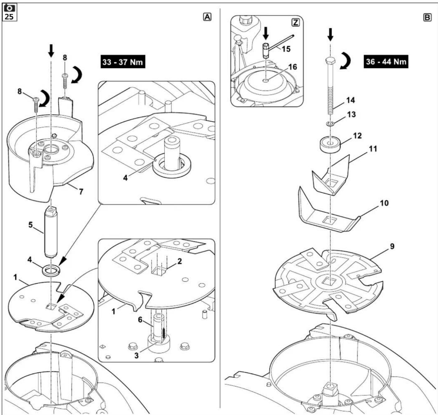
1. Insert the hard material blade disc (Figure A)
- Insert the hard material blade disc (1) with the three fitted blades facing upwards.
Allow the rectangular blade mounting (2) of the blade disc to engage in the rectangular mounting (3) in the bearing ring.
2. Install the blade holder with the clamping ring (Figure A):
Position the notch in the clamping ring at the corner of the blade so that the clamping ring lies flat on the blade disc.
- Place the clamping ring (4) onto the blade disc (notch in the clamping ring must enclose the blade).
- Push the blade holder (5) onto the drive shaft (6). Make sure that the blade holder engages in the blade disc (1) and drops down in the clamping ring (4) as far as possible.
3. Install the insert (Figure A):
The insert can only be installed as shown. It cannot be inserted in any other position.
• Install the insert (7) as shown.
- Screw in the screws (8) and tighten to 33 - 37 Nm.
4. Insert the soft material blade disc and wing blade (Figure B):
- Insert the soft material blade disc (9) with the four fitted blades facing upwards.
Always insert the longer wing blade of the two first. Then insert the second wing blade at 90° to the first wing blade.
- Insert the long wing blade (10). Insert the short wing blade (11) at 90° to the long wing blade.
5. Fasten the blade discs (Figure B):
- Attach the clamping ring (12) and tighten together with the lock washer (13) and the blade fastening screw (14).
- Position the assembly tool (15) on the blade fastening screw (14) and turn clockwise slowly and carefully until the blade discs are stopped by the stop. Detach the assembly tool (15).

Risk of injury:
The blade cover must always be attached in order to tighten the blade fastening screw (see view Z).
• Install the blade cover. ( 7.4)
- Insert the assembly tool (15) into the bore of the blade cover (16) and position on the blade fastening screw (14).
- Tighten the blade fastening screw (14) to 36 - 44 Nm.
• Install the feed chute ATO 400. (⇔ 7.5)
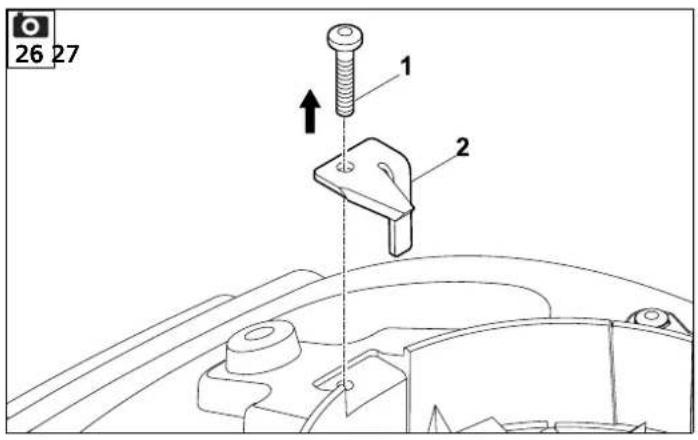
12.5 Removing the counter-blade


Risk of injury:
Always wear thick gloves.

- Remove the feed chute ATO 400 and the blade cover. (⇒ 12.2), (⇒ 7.3)
• Unscrew and remove the screw (1). - Remove the counter-blade (2) from above.
12.6 Installing the counter-blade


Risk of injury:
Always wear thick gloves.

- Remove the feed chute ATO 400 and the blade cover. (⇒ 12.2), (⇒ 7.3)
- Insert the counter-blade (1) into the mounting (2) in the housing.
- Screw in the screw (3) and tighten to 28 - 32 Nm.
• Install the feed chute ATO 400. ( 7.5)
12.7 Reversing the blades


Risk of injury: Always wear thick gloves.


When the blades are blunt, we recommend that you reverse all the blades on the particular blade disc. All blades (regardless of the blade geometry) are reversed in the same way.
- Removing the blade discs. (⇒ 12.3)

Risk of injury: To prevent injuries, always clamp down the blade discs before installing or removing the blades.
Reversing the four blades of the soft material blade disc (Figure A):
1. Removing:
- Unscrew screws (1) and remove together with nuts (2).
- Remove blade (3) upwards.
2. To install:
- Clean the blade disc.
- Reverse blade (3) and place onto the blade disc with the sharp edge exposed and align the bores.
- Insert screws (1) through the bores and screw on nuts (2). Tighten nuts (2) to 8 --10 Nm.
Reversing the three blades of the hard material blade disc (Figure B):
1. Removing:
- Unscrew the screws (4) and M8 screws (5) and remove them together with the nuts (6) and M8 nuts (7).
- Lift off the blades (8) and blade (9).
2. To install:

There must be no gap between the two blades (8) following installation. A gap between the two blades impairs the feeding function.
- Clean the blade disc.
- Reverse the blades (8) and place onto the blade disc with the sharp edge exposed and align the bores.
- Insert screws (4) through the bores and screw on nuts (6). Do not tighten.
- Press the two blades (8) together (see small illustration) and hold. There must be no gap between the two blades (8).
• Tighten nuts (6) to 8 - -10 Nm.
- Reverse the blade (9) and place onto the blade disc with the sharp edge exposed.
- Insert the M8 screws (5) through the bores, screw on the M8 nuts (7) and tighten to 16 - 20 Nm.
12.8 Sharpening the blades

We recommend that all blades are sharpened only by a specialist dealer, as the function (drawing in of shredding material, durability of the cutting edges etc.) of the garden shredder may deteriorate if blades are ground incorrectly (wrong sharpening angle, imbalanced due to unevenly ground blades etc.).
Always wear safety glasses when sharpening. Make sure that others are kept out of the danger area.
- Removing the blade discs. (⇒ 12.3)
- Remove the blade. (⇒ 12.7)
Sharpening angle:
The sharpening angle for all the blades is 30^ .
Instructions for sharpening the blades:
The following points must be observed when re-sharpening the blades:
- Cool the blades when sharpening, e.g. with water. The blade must not be allowed to display blue colouring, as this would reduce its cutting quality.
- Sharpen the blade evenly to prevent vibrations due to imbalance.
- Check blades for damage before installing: The blades must be replaced if notches or cracks are visible or if the blades have reached the wear limits.
- Re-sharpen the cutting edges to the specified sharpening angle.
- Sharpen the blades against the cutting edge.
- After sharpening, remove any sharpening burr at the cutting edge using fine sandpaper.
12.9 Wear limits of the blades


The blades must be reversed or replaced before reaching the specified wear limits (A, B, C, D). STIHL recommends STIHL specialist dealers.

The specified values should be measured at several points (two or three recommended) along the cutting edge on all the blades.
Use the smallest value for a blade.
We recommend that you always reverse or replace all the blades at the same time.
1 Blade overview
2 wing blades (1)
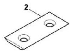
6 blades (2)
1 blades (3)
1 counter-blade (4)
Soft material blade disc:
The soft material blade disc is fitted with four blades.
Hard material blade disc:
The hard material blade disc is fitted with two blades and one chipping blade.
- Removing the blade discs. (⇒ 12.3)
2 wear limit of wing blades (1):

The measurement procedure and the value specified are the same for both wing blades.
Asymmetrical wear may occur at the two wing blades due to uneven use of the cutting edges.
Minimum blade width (A) of the two wing blades (1):
A = 39 mm
3 Wear limit of blades (2):

The blades (2) are reversible blades. After reaching the specified wear limit (B), the blade can be re-sharpened and reversed until the wear limit is reached, before needing to be replaced.
- Measure the distance (B) shown in the illustration from the large diameter of the bore to the cutting edge (X).
- Repeat this procedure at the second bore on the blade.
Minimum distance (B) on the blades (2): B = 6 mm

The particular blade (2) must be reversed or replaced if one of the two distances measured is less than the minimum distance (B).
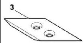
4 Wear limit of blade (3):

The blade (3) is a reversible blade. On reaching the specified wear limit (C), the blade (3) can be re-sharpened and reversed until the wear limit is reached, before needing to be replaced.
- Measure the distance (C) at a right angle to the cutting edge.
Minimum distance (C) on the blade (3): C = 7 mm

The blade (3) must be reversed or replaced if the distance measured is less than the minimum distance (C).
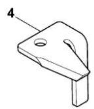
5Wear limit of counter-blade (4):

Asymmetrical wear may occur at the counter-blade (4) due to uneven use of the cutting edge.
- The counter-blade (4) must be replaced before the edge (D) at the tip (5) of the blade is ground down and no longer visible.
12.10 Service interval of the combustion engine
Maintenance interval: Before each use:
Perform oil check ( engine instruction manual). Observe the operating and maintenance instructions contained in the accompanying engine instruction manual.
12.11 Service intervals
Service by the specialist dealer
We recommend that you have your garden shredder serviced once a year by a specialist dealer.
STIHL recommends STIHL specialist dealers.
Professional use (commercial use of the garden shredder): every six months
Private use: once a year
Service intervals for cutting unit:
Before each use:
Check that the cutting unit (consisting of blade disc, blades, retaining washer, clamping ring and screw) is seated securely and that there are no cracks or other damage.
Check the wear limits of the blades.
(⇒ 12.9)
12.12 Wheels

The slide bearings of the wheels are maintenance-free.
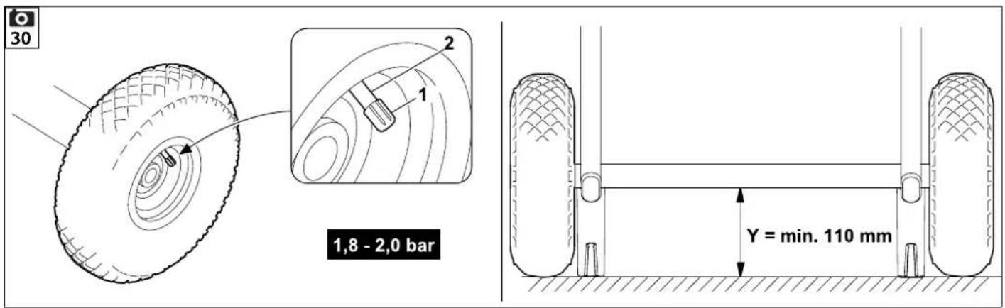
Tyre pressure:
1.8 - 2.0 bar
Maintenance interval:
Check and if necessary correct the tyre pressure of the wheels before using the garden shredder and after extended periods when not in use.
Correcting the tyre pressure:
- Unscrew the valve cap (1) from the valve (2) and set the specified tyre pressure using a suitable pressure gauge.
- Screw the cap (1) onto the valve (2).
Checking procedure of the tyre pressure without a pressure gauge:
If a pressure gauge is not available for adjusting the tyre pressure, the pressure can be checked using the control dimension (Y) from the axle to the ground.
Minimum distance Y = 110 m m
12.13 Storage and winter break
Store the garden shredder in a dry and locked place that is generally free of dust. Make sure that the machine is kept out of the reach of children.
Only store the garden shredder in good operating condition and with the feed chute ATO 400 or blade cover fitted.
Keep all nuts, pins and bolts tightly fastened, replace danger signs and warnings on the appliance that have become illegible, check the entire machine for wear and damage. Replace all worn or damaged parts.
Any machine faults must be completely remedied prior to storage.
Note the following points when storing the garden shredder for extended periods (over winter):
- Thoroughly clean all external parts of the machine
- Thoroughly lubricate/grease all moving parts.
- Empty fuel tank and carburettor (e.g. by running the engine).
- Unscrew spark plug and pour approx. 3 cm ^3 of engine oil into the engine via the spark plug hole. Turn the engine several times with the spark plug removed.

Fire hazard!
Keep the spark plug socket away from the spark plug hole (danger of ignition).
• Re-install the spark plug.
- Perform oil change (⇒ engine instruction manual).
- Cover the engine well and store the machine in a dry, dust-free room in the upright position.
13. Transport


Risk of injury:
Carefully read and observe the section entitled "For your safety", in particular the "Transport" section. ( 4.4)
Only transport the garden shredder with the feed chute ATO 400 fitted and the branch guide folded in.
If the garden shredder is transported without the feed chute ATO 400, the blade cover must be fitted for safety reasons (exposed blades). ( 7.4)
The garden shredder must be carried by three persons wearing suitable safety clothing (safety shoes, gloves).
Before lifting or tilting the machine, note the weight indicated in the "Technical specifications" section. ( 18.)
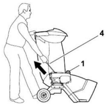
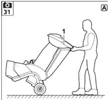
Pulling or pushing the garden shredder (Figure A):
- Hold the garden shredder at the transport handle (1) and tilt to the rear until the machine is standing on its wheels.
- The garden shredder can be pulled or pushed slowly (walking pace).

Risk of injury at steps, stepped areas and sloping ramps.
Because of the weight, particular care is required at steps, kerbs, stepped areas, other raised areas and sloping ramps.
Push and do not pull the machine down steps, stepped areas and other raised areas and sloping ramps. The user must always stand higher than the machine, in order to avoid being run over by the machine in the case of loss of control.
Do not push the machine down more than two or three steps. Where there are more steps, carry the machine with the help of two other persons.
Risk of injury due to the heavy weight of the machine.
Lifting or carrying the garden shredder (Figure B):

Due to its heavy weight (> 50 kg), we strongly recommend that you do not carry the machine, but only move it on its wheels by pushing.
Suitable lifters must be used when lifting or carrying the machine for short distances.
Three persons are always required for manual lifting. The machine must be ho each wheel carrier and at the feed chute. Wear suitable protective clothing; the lower arms and upper part of the body must be fully covered.

- Hold the garden shredder at the transport handle (1) and at the two black feet (2) and lift/carry.
Transporting the garden shredder on a load floor (Figure C):

Risk of injury:
Always secure the garden shredder before transporting. Never transport the machine unsecured.
When transporting the garden shredder, secure it on a load floor using suitable fastening material to prevent it from slipping. Attach ropes or straps at the following points on the machine:
- Axle (inside of the wheel carrier)
- Left wheel carrier
- Right wheel carrier
- Feed chute ATO 400
14. Minimising wear and preventing damage
Important information on maintenance and care of the product group
petrol garden shredder (STIHL GH)
STIHL assumes no liability for material or personal damage caused by the non-observance of information contained in the operating instructions, in particular with regard to safety, operation and maintenance, or which arise through the use of unauthorised attachment or spare parts.
Please always observe the following important information for the prevention of damage or excessive wear to your STIHL machine:
1. Wearing parts
Some parts of the STIHL machine are subject to normal wear even when used properly and must be replaced in due time depending on type and duration of use.
These include:
- Blade
- Blade disc
- V - b e l t
2. Compliance with the information in this instruction manual
The STIHL machine must be used, maintained and stored with the care described in this instruction manual. Any damage caused by non-compliance with the safety, operating and maintenance instructions is the sole responsibility of the user.
This applies in particular to:
- Improper use of the product.
- Use of fuel and lubricants not approved by STIHL (lubricants, petrol and engine oil, see engine instruction manual).
– Product modifications not approved by STIHL.
– The use of attaching parts, attachments or cutting tools not approved by STIHL.
– Use of the product for sporting or competitive events. - Resultant damage due to continued use of the product with defective components.
3. Maintenance operations
All operations listed in the section "Maintenance" must be performed regularly.
If these maintenance operations cannot be carried out by the user, a specialist dealer must be commissioned to perform them.
STIHL recommends that you have maintenance operations and repairs performed exclusively by a STIHL specialist dealer.
STIHL specialist dealers regularly attend training courses and are provided with technical information.
If these operations are neglected, faults may arise which are the responsibility of the user.
These include:
- Corrosive and other resultant damage caused by incorrect storage.
– Damage and resultant damage due to the use of spare parts which are not original STIHL parts.
– Damage due to maintenance and repair operations not performed in the workshops of authorised specialist dealers.
15. Standard spare parts
Soft material blade disc assembly: 6012 700 5110
Hard material blade disc assembly: 6012 700 5100
Long wing blade: 6012 702 0310
Short wing blade: 6012 702 0300
Blade (x6): 6008 702 0121
Blade (x1): 6012 702 0100
Counter-blade: 6012 702 0500
16. Environmental protection

Shredding material should be composted and not disposed of in household waste.
The machine, its packaging and accessories are all produced
from recyclable materials and must be disposed of accordingly.
By disposing of materials separately, and in an environmentally friendly manner, valuable resources can be re-used. For this reason, the machine should be disposed of for recycling at the end of its useful life.
16.1 Disposal
Render the engine unusable prior to disposal.
In particular, remove the ignition lead, empty the fuel tank and drain the engine oil.
Risk of injury from the blades.
Always store an old garden shredder in a safe place prior to scrapping. Make sure that the machine and the blades are kept out of the reach of children.
17. EU - Declaration of conformity
17.1 STIHL GH 460.0, GH 460.0 C Garden Shredder
declares under our sole responsibility that
- design: garden shredder
– manufacturer's brand: STIHL
-type: GH 460.0, GH 460.0 C - serial number: 6012
complies with the relevant provisions of Directives 2000/14/EC, 2006/42/EC, 2014/30/EU and 2011/65/EU and has been developed and manufactured in accordance with the versions of the following standards valid on the date of manufacture: EN 13683 and EN 14982 (where applicable).
Name and address of the notified body involved:
TÜV Rheinland LGA Products GmbH Tillystrasse 2 D-90431 Nuremberg
The measured and guaranteed sound power levels were determined in accordance with Directive 2000/14/EC, Appendix V.
GH 460.0
- Measured sound power level: 101.4 dB(A)
– Guaranteed sound power level: 104 dB(A)
GH 460.0 C
- Measured sound power level: 103.4 dB(A)
– Guaranteed sound power level: 108 dB(A)
The technical documents are stored in the Product Approval department at STIHL Tirol GmbH.
The year of manufacture and machine number are indicated on the garden shredder.
Langkampfen, 02.01.2021
STIHL Tirol GmbH
p.p.

Matthias Fleischer, Head of Research and Development Division
p.p.

Sven Zimmermann, Head of Quality Division
Importer for Great Britain
ANDREAS STIHL Ltd.
Stihl House
Stanhope Road
CAMBERLEY
SURREY GU15 3YT
Great Britain
18. Technical specifications
GH 460.0 / GH 460.0 C:
Serial number 6012
Starter Rope start
Cutting unit MultiCut 450
Cutting unit drive Permanent
Wheel diameter 260 mm
GH 460.0:
| Engine, design | 4-stroke combustion engineB&S Series 850 |
| Type | EXi OHV |
| Nominal output at nominal speed | 3,4 - 3000kW - rpm |
| Displacement | 190 ccm |
| Fuel tank | 1,0 l |
| Maximum branch diameter | 60 mm |
| Nominal engine speed | 3000 rpm |
| In accordance with Directive2000/14/EC:Guaranteed sound power level L_WAd | 104 dB(A) |
| In accordance with Directive2006/42/EC:Sound pressure level at workplace L_pA | 96 dB(A) |
| Uncertainty K_pA | 3 dB(A) |
GH 460.0:
| L/W/H | 108/85/137 cm |
| Weight | 59 kg |
GH 460.0 C:
| Engine, design | 4-stroke combustion engine |
| Type | B&S Power built OHV (Series 3115) |
| Nominal output at nominal speed | 5,8 - 2800 kW - rpm |
| Displacement | 344 ccm |
| Fuel tank | 2,3 l |
| Maximum branch diameter | 75 mm |
| Nominal engine speed | 2800 rpm |
| In accordance with Directive | |
| 2000/14/EC: Guaranteed sound power level L_WAd | 108 dB(A) |
| In accordance with Directive | |
| 2006/42/EC: Sound pressure level at workplace L_pA | 97 dB(A) |
| Uncertainty K_pA | 3 dB(A) |
| L/W/H | 108/89/137 cm |
| Weight | 75 kg |
18.1 REACH
REACH is an EC Directive for the registration, evaluation, authorisation and restriction of chemicals.
Information on compliance with the REACH Directive (EC) No. 1907/2006 is available from www.stihl.com/reach.
19. Troubleshooting
See engine instruction manual.
If necessary, contact a specialist dealer; STIHL recommends STIHL specialist dealers.
Fault:
Engine not starting
Possible cause:
- On / Off switch not operated
- Feed chute not properly closed - safety cut-off switch actuated (safety interlock)
- Blocked blade disc
– No fuel in tank; blocked fuel line
– GH 460 C: Tank ventilation screw closed
– Inferior, dirty or old fuel in tank - Spark plug socket detached from spark plug; ignition lead not properly fastened to socket
– Dirty air filter
– Dirty or damaged spark plug; incorrect electrode gap
Remedy:
- Operate On / Off switch ( 8.1)
- Close feed chute properly and fasten (tighten On / Off switch) ( 7.5)
- Remove shredder deposits from housing (IMPORTANT: Detach spark plug socket)
- Top up fuel; clean fuel line ( 7.8)
- Start machine in accordance with instructions (GH 460 C: open tank ventilation screw) (⇒ 11.1)
-
Always use fresh, good quality fuel, normal unleaded petrol; clean carburettor ( 7.8)
-
Connect spark plug socket; check connection between ignition lead and socket 📄 ✗
- Clean air filter 📄 ✗
- Clean or replace spark plug; adjust electrode gap 📄 ✗
Fault:
Engine overheating
Possible cause:
– Dirty cooling ribs
– Oil level in engine too low
– Surface of engine covered with shredded material
Remedy:
- Clean cooling ribs ( 12.1)
- Top up engine oil (⇒ 7.8)
- Remove shredded material from the engine
Fault:
Excessive vibration during operation
Possible cause:
– Faulty blade disc or blades
- Loose engine mounting
Remedy:
- Check blade discs, blades, blade shaft, screws, nuts, washers and bearings of cutting unit, repair if necessary ✗
- Tighten engine mounting bolts ✗
Fault:
Starting problems or deteriorating engine power
Possible cause:
– Shredding material in housing
– Water in fuel tank and carburettor; carburettor blocked
- GH 460 C: Tank ventilation screw closed or not fully open
- Contaminated fuel tank
- Dirty air filter
- Dirty spark plug
Remedy:
- Remove shredder deposits from housing (detach spark plug socket) ( 12.1)
- Empty fuel tank, ✗ clean fuel line and carburettor
- GH 460 C: Start machine in accordance with instructions (open tank ventilation screw) ( 11.1)
- Clean fuel tank 📄 ✗
- Clean air filter 📄 ✗
- Clean spark plug 📄 ✗
Fault:
Reduced shredding performance
Possible cause:
- Blunt blades
- Incorrectly ground blades
- Bent blade disc
Remedy:
- Re-sharpen or replace blades ( 12.8) ✗
- Sharpen blades correctly (⇒ 12.8) ✗
- Visually inspect blade disc and replace if necessary ( 12.3)
Fault:
Shredding material is not drawn in
Possible cause:
- Blunt or incorrectly ground blades
- Gap between the two blades (hard material blade disc)
- Blade cover not removed
Remedy:
-Regrind blade and ensure sharpening angle is exactly correct X ( 12.8)
- Install blades onto the hard material blade disc without a gap ( 12.7)
- Remove blade cover (⇒ 7.3)
20. Service schedule
20.1 Handover confirmation
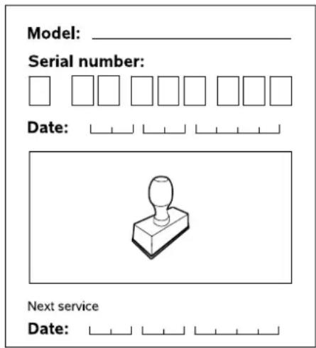
text_image
Model: ____ Serial number: Date: Next service Date:20.2 Service confirmation
Please hand this instruction manual to your STIHL specialist dealer in the case of maintenance operations. He will confirm the service operations performed in the pre-printed boxes.

Service performed on

Next service date

Chère cliente, cher client,
Distance minimale Y = 110 mm
natural_image
Simple line drawing of a mechanical component with a cylindrical top and rectangular base (no text or symbols)Prochain entretien
Date: ____ ____ ____ ____ ____
| Verbrandingsmotor,type | 4-taktverbrandingsmo-tor |
| Type | B&S Power built |
Nominaal vermogen
natural_image
Simple line drawing of a mechanical component with a cylindrical top and rectangular base (no text or symbols)GH 460.0 / GH 460.0 C:
Serbatoio carburante 1,0 l
Diametro ramo
massimo 60 mm
GH 460.0 / GH 460.0 C:
GH 460.0 / GH 460.0 C:
Long./Anch./Alt. 108/85/137 cm
Peso 59 kg
GH 460.0 C:
Tipo B&S Power built
OHV (Series
3115)
GH 460.0 C:
natural_image
Simple line drawing of a mechanical component with a cylindrical top and rectangular base (no text or symbols)Próxima revisión
Fecha: ____ ____ ____ ____ ____
Montar as chapas 198
Virar as lâminas 206
Afiar as lâminas 207
Limites de desgaste das lâminas 207
Q Parafuso Torx 2 M6x16
R Porca M6 3
S Chave de parafusos 1
7.7 Montar as chapas
1 Montar a chapa de guia
12.7 Virar as lâminas


12.8 Afiar as lâminas

GH 460.0 / GH 460.0 C:
natural_image
Simple line drawing of a mechanical component with a cylindrical top and rectangular base (no text or symbols)P Flathodet skrue 1 M6x16
Q Torx-skrue 2 M6x16
R Mutter M6 3
S Skrunøkkel 1
T Monteringsverktøy 1
U Sekskantskrue 1 M14x130
• Bruksanvisning 1
• Bruksanvisning for forbrenningsmotor 1
GH 460.0 / GH 460.0 C:
natural_image
Simple line drawing of a mechanical component with a cylindrical top and rectangular base (no text or symbols)Neste service
Dato:

GH 460.0 / GH 460.0 C:
Modellnummer 6012
natural_image
Simple line drawing of a mechanical component with a cylindrical top and rectangular base (no text or symbols)Nästa service
Datum:
20.2 Servicebekräftelse
GH 460.0 / GH 460.0 C:
Sarjatunnus 6012
natural_image
Simple line drawing of a mechanical component with a cylindrical top and rectangular base (no text or symbols)GH 460.0 / GH 460.0 C:
Serienummer 6012
GH 460.0 / GH 460.0 C:
natural_image
Simple line drawing of a mechanical component with a cylindrical top and rectangular base (no text or symbols)Næste service

GH 460.0 / GH 460.0 C:
natural_image
Simple line drawing of a mechanical component with a cylindrical top and rectangular base (no text or symbols)Następny przegląd
Data: ____ ____ ____ ____ ____
GH 460.0 / GH 460.0 C:
Sériové identifikačné
číslo 6012
Štartovací
mechanizmus
Štartovacie
lanko
Chybná rezná
jednotka MultiCut 450
Pohon reznej
jednotky trvalý
Priemer kolesa 260 mm
GH 460.0:
natural_image
Simple line drawing of a mechanical component with a cylindrical top and rectangular base (no text or symbols)Đalší servis
Dátum: ____ ____ ____ ____ ____
natural_image
Industrial water purifier machine with control panel and wheels (no visible text or symbols)B
INT 1

text_image
Black and white barcode image with vertical lines, no visible text or symbols0478 216 9906 B