IB 15120 - Steam cleaner Kärcher - Free user manual and instructions
Find the device manual for free IB 15120 Kärcher in PDF.
| Product type | Dry ice blaster |
| Brand | Kärcher |
| Model | IB 15120 |
| Power supply | 220-240 V ~ 50 Hz, 0.6 kW |
| Compressed air supply | Pressure 0.2-1.6 MPa (2-16 bar), flow rate 2-12 m³/min |
| Maximum jet pressure | 1.6 MPa (16 bar) |
| Dry ice consumption | 30-120 kg/h |
| Dry ice tank capacity | 40 kg |
| Dimensions (L x D x H) | 716 x 850 x 1102 mm |
| Weight with accessories | 101.5 kg |
| Weight ready for operation | 140 kg |
| Protection rating | IPX4 |
| Sound pressure level | 114 dB(A) |
| Sound power level | 136 dB(A) |
| Dry ice temperature | -79 °C |
| Safety | Emergency stop, CO2 detection, grounding, electric shock protection (30 mA circuit breaker) |
| Recommended protective equipment | Splash goggles, cold protection gloves, hearing protection, protective clothing |
| Maintenance | Daily (check hose and cables); every 100 h (couplings, metering); every 500 h or annually (service check); every 2 years (hose replacement) |
| Included accessories | Blasting gun, round jet nozzles (L, M), flat jet nozzle, protective hose, etc. |
| Warranty | According to country conditions, contact dealer or Kärcher service |
Frequently Asked Questions - IB 15120 Kärcher
User questions about IB 15120 Kärcher
0 question about this device. Answer the ones you know or ask your own.
Ask a new question about this device
Download the instructions for your Steam cleaner in PDF format for free! Find your manual IB 15120 - Kärcher and take your electronic device back in hand. On this page are published all the documents necessary for the use of your device. IB 15120 by Kärcher.
USER MANUAL IB 15120 Kärcher
natural_image
Line drawing of a Karcher professional gas station with wheels and control panel (no text or symbols on the device itself)Deutsch 3
English 15
Français 27
Italiano 39
Nederlands 52
Español 64
Português 77
Dansk 90
Norsk 102
Svenska 113
Suomi 125
Ελληνικά 137
Türkçe 149
Русский 161
Magyar 174
Čeština 186
Slovenščina 198
Polski 210
Românește 222
Slovenčina 234
Hrvatski 246
Srpski 258
Български 270
Eesti 283
Latviešu 295
Lietuviškai 307
Українська 318
中文 331
⚠Gefahr
natural_image
Line drawing of a cylindrical mechanical component with flanges and a central shaft (no text or symbols)natural_image
Simple line drawing of a bolt with a flanged cap (no text or symbols)natural_image
Technical line drawing of a mechanical pulley or wheel assembly (no text or symbols)
Chairman of the Board of Management
Director Regulatory Affairs & Certification
71364 Winnenden (Germany)
Tel.: +49 7195 14-0
Fax: +49 7195 14-2212
Winnenden, 2021/02/01
Please read and comply with these original instructions prior
to the initial operation of your appliance and store them for later use or subsequent owners.
Contents
Environmental protection .. EN .. 1
Safety instructions ..... EN .. 1
Proper use ..... EN .. 2
Function ..... EN .. 2
Control elements..... EN .. 3
Start up.... EN .. 4
Operation.... EN .. 6
Shutting down..... EN .. 8
Transport..... EN .. 8
Storage.... EN .. 8
Maintenance and care .... EN .. 8
Troubleshooting ..... EN .. 9
Technical specifications ... EN . 11
Accessories ..... EN . 12
Warranty ..... EN . 12
EU Declaration of Conformity EN . 12
Declaration of Conformity .. EN . 12
Environmental protection

The packaging material can be recycled. Please do not place the packaging into the ordinary refuse for disposal, but arrange for the proper recycling.

Old appliances contain valuable materials that can be recycled; these should be sent for recycling. Batteries, oil, and similar substances must not enter the environment. Please dispose of your old appliances using appropriate collection systems.
Notes about the ingredients (REACH)
You will find current information about the ingredients at:
www.kaercher.com/REACH
Safety instructions
The appliance may only be operated by persons who have read and understood the contents of this operating instructions manual. Please ensure that you conform to all the safety instructions and regulations.
→ This operating instructions manual must be stored in such a way that it can be easily accessed by the operator.
Danger or hazard levels
⚠️Danger
Immediate danger that can cause severe injury or even death.
⚠ Warning
Possible hazardous situation that could lead to severe injury or even death.
Caution
Possible hazardous situation that could lead to mild injury to persons or damage to property.
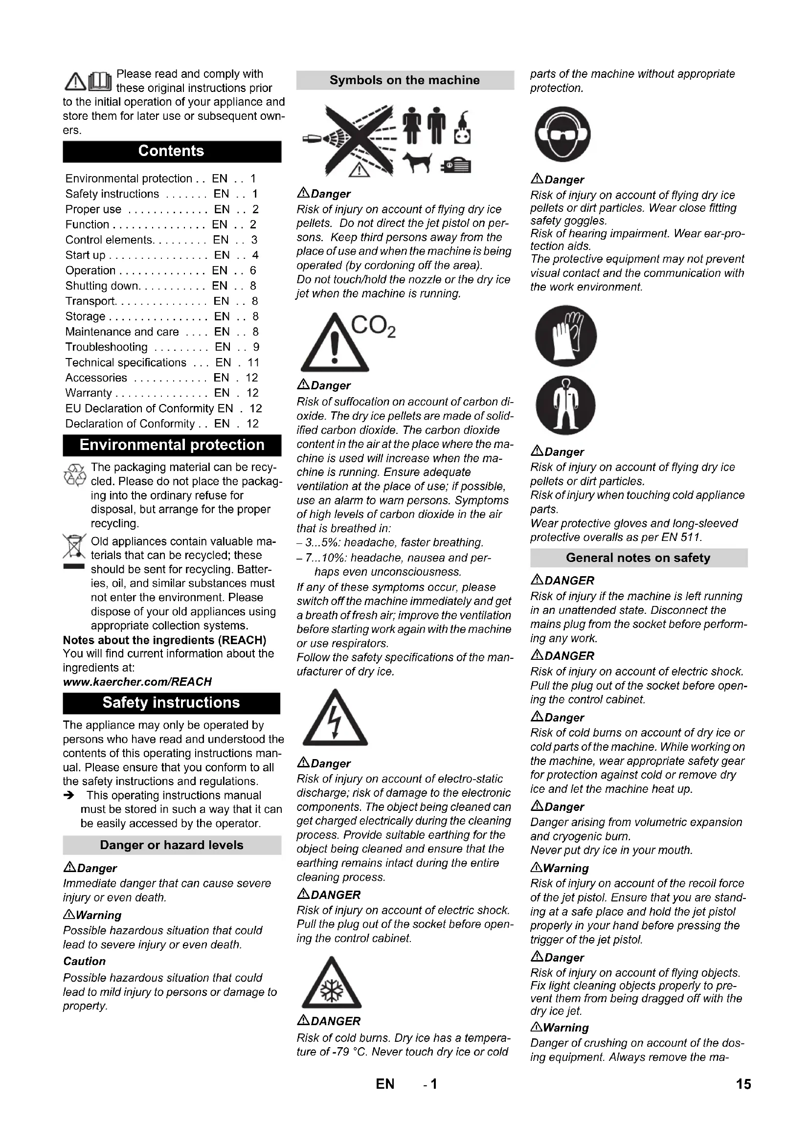
Symbols on the machine

⚠️Danger
Risk of injury on account of flying dry ice pellets. Do not direct the jet pistol on persons. Keep third persons away from the place of use and when the machine is being operated (by cording off the area). Do not touch/hold the nozzle or the dry ice jet when the machine is running.
⚠️Danger
Risk of suffocation on account of carbon dioxide. The dry ice pellets are made of solidified carbon dioxide. The carbon dioxide content in the air at the place where the machine is used will increase when the machine is running. Ensure adequate ventilation at the place of use; if possible, use an alarm to warn persons. Symptoms of high levels of carbon dioxide in the air that is breathed in:
- 3...5%: headache, faster breathing.
- 7...10%: headache, nausea and perhaps even unconsciousness.
If any of these symptoms occur, please switch off the machine immediately and get a breath of fresh air; improve the ventilation before starting work again with the machine or use respirators.
Follow the safety specifications of the manufacturer of dry ice.
⚠️Danger
Risk of injury on account of electro-static discharge; risk of damage to the electronic components. The object being cleaned can get charged electrically during the cleaning process. Provide suitable earthing for the object being cleaned and ensure that the earthing remains intact during the entire cleaning process.
⚠️DANGER
Risk of injury on account of electric shock. Pull the plug out of the socket before opening the control cabinet.
⚠️DANGER
Risk of cold burns. Dry ice has a temperature of -79 °C. Never touch dry ice or cold parts of the machine without appropriate protection.

⚠ Danger
Risk of injury on account of flying dry ice pellets or dirt particles. Wear close fitting safety goggles.
Risk of hearing impairment. Wear ear-protection aids.
The protective equipment may not prevent visual contact and the communication with the work environment.

Danger
Risk of injury on account of flying dry ice pellets or dirt particles.
Risk of injury when touching cold appliance parts.
Wear protective gloves and long-sleeved protective overalls as per EN 511.
General notes on safety
DANGER
Risk of injury if the machine is left running in an unattended state. Disconnect the mains plug from the socket before performing any work.
DANGER
Risk of injury on account of electric shock. Pull the plug out of the socket before opening the control cabinet.
⚠️Danger
Risk of cold burns on account of dry ice or cold parts of the machine. While working on the machine, wear appropriate safety gear for protection against cold or remove dry ice and let the machine heat up.
⚠️Danger
Danger arising from volumetric expansion and cryogenic burn.
Never put dry ice in your mouth.
⚠ Warning
Risk of injury on account of the recoil force of the jet pistol. Ensure that you are standing at a safe place and hold the jet pistol properly in your hand before pressing the trigger of the jet pistol.
⚠️Danger
Risk of injury on account of flying objects. Fix light cleaning objects properly to prevent them from being dragged off with the dry ice jet.
⚠ Warning
Danger of crushing on account of the dosing equipment. Always remove the ma-
chine plug from the socket before removing the protective shield of the dry ice container.
Specifications and Guidelines
For the operation of this system the following regulations and directives are applicable in the Federal Republic of Germany (available from Carl Heymanns Verlag KG, Luxemburger Straße 449, 50939 Cologne):
– BGV D 26 Spray jet tasks
– Executing instructions for BGV D 26
– BGR 117 Working in closed rooms
– BGR 139 safety rules for persons - emergency signal systems.
– BGR 189 Using safety gear
– BGR 195 Using of safety gloves
– BGR 500 use of work equipment
– BGI 534 Working in closed rooms
- BGI 836 Gas warner
Observe national safety provisions and safety instructions as well as national provisions of occupational health and safety agencies and trade associations!
Safety Devices
Emergency-stop button
If the emergency stop button is pressed, the dry ice dosing is stopped and the air flow from the nozzle is interrupted.
Switch-off in case of emergency
→ Release the trigger of the jet pistol.
→ Press emergency-stop button.
The dry ice dosing is stopped and the air flow from the nozzle is interrupted.
→ Interrupt the compressed air supply.
Proper use
The machine is used to remove dirt using dry ice pellets that are speeded up using an air jet.
The machine should not be operated in explosive environments.
Use only dry ice pellets as jet medium. Using any other jet medium can cause damage to the machine.
Function
The air pressure reaches the jet pistol via a pressure regulation valve. The valve opens when the trigger of the jet pistol is pressed and the air flow comes out from the jet pistol. Additionally, dry ice pellets are dosed into the air jet via the dosing device. The additional dosing can be switched off by means of the operating mode switch. The dry ice pellets hit the surface to be cleaned and remove the dirt. Additional thermal stress occurs between the dirt and the object to be cleaned due to the -79 °C cold dry ice pellets; this contributes to the removal of the dirt. At the same time, dry ice immediately gets coverted into gaseous carbon dioxide on contact and requires 700 times the volume of dry ice. Thus, the dirt penetrated by the dry ice thus gets thrown off. During the spraying operation through the jet, a vibrator located on the dry ice container ensures continuous sliding of the dry ice pellets.
Control elements
Device
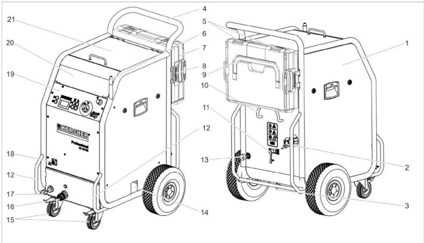
1 Fuse F1, below the side panel
2 Compressed air connection
3 Condensate drain-out
4 Push handle
5 Closure, case
6 Holder for jet pistol
7 Case for accessories
8 Unlocking device, case mounting
9 Carrying handle, case
10 Cable clamp
11 Pressure relief valve, condensate draining of the water separator
12 Transport handle, bumper at the rear
13 Mains cable with mains plug
14 Dry ice outlet for emptying the container
15 Guiding roll with fixed position brake
16 Coupling spray agent hose
17 Earth wire with clamp
18 Coupling of the control cable
19 Operating field
20 Storage compartment for accessories
21 Cover of the dry ice container
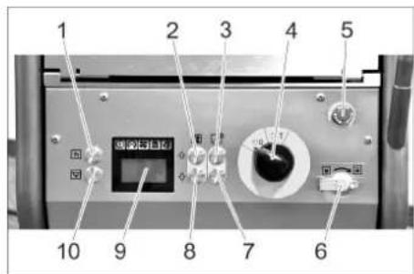
Operating field Display

1 Statistics key, reset counter
2 Key "increase jet pressure"
3 Increase the dry ice dosing
4 Power switch
5 Emergency-stop button
6 Key switch
7 Decrease the dry ice dosing
8 Key "decrease jet pressure"
9 Display
10 Key to empty the dry ice container
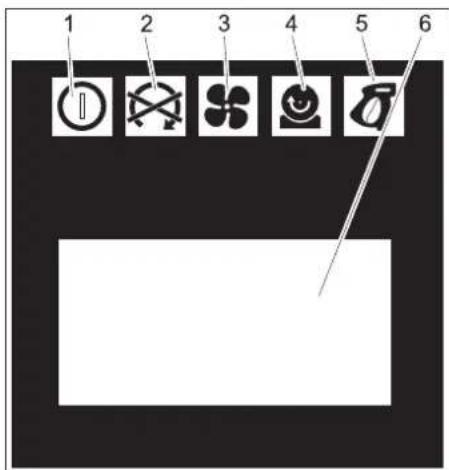
1 Indicator lamp - control voltage
green: Control voltage OK
red: Control voltage too low
yellow: Emptying of dry ice container active
2 Indicator lamp emergency STOP
red: Emergency stop button activated
green: Emergency stop button not activated
3 Indicator lamp - compressed air
green: Pressure OK
orange: selected jet pressure not reached
red: Pressure too low (below 0.15 MPa/1.5 bar)
4 Indicator lamp – dosing device
green: Drive OK
red: Error in drive
5 Indicator lamp - jet pistol green: Jet pistol OK orange: The trigger of the jet pistol was activated during the switch-on process red: Jet pistol disconnected or control line damaged
6 Display field
Jet equipment
Jet gun

1 Nozzle
2 Jet pistol
3 Coupling spray agent hose
4 Coupling of the control cable
5 Safety lever
6 Trigger
7 Operating type switch
Position "1": Compressed air jet
Position "2": Dry ice jet (compressed air and dry ice pellets)
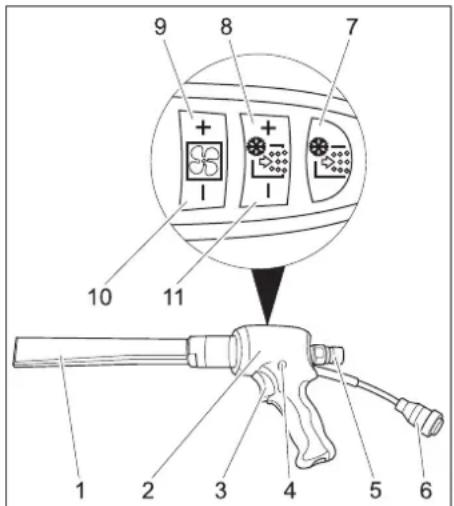
Jet pistol Advanced (option)

1 Nozzle
2 Jet pistol
3 Trigger
4 Safety button
5 Coupling spray agent hose
6 Coupling of the control cable
7 Key for the dry ice dosing on/off
Illuminates red when the dry ice dosaging is switched off
8 Increase the dry ice dosing
9 Key "increase jet pressure"
10 Key "decrease jet pressure"
11 Decrease the dry ice dosing
Case for accessories
The case serves the storage of the nozzles and the associated tools.
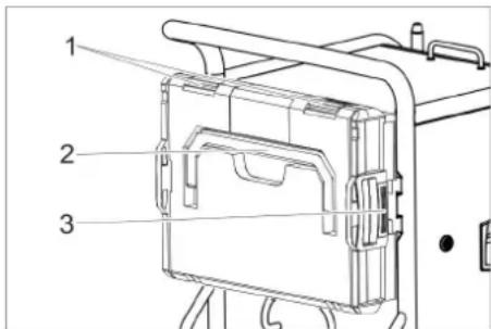
1 Lock
2 Carrying handle
3 Unlocking
Opening the case
→ Open locks.
→ Swivel the lid downwards.
Caution
Risk of damage, do not place heavy objects on the opened lid.
Separating the case from the appliance.
→ Push the unlocking devices and remove the case.
Attaching the case to the appliance.
→ Turn the case so that the closures are pointing upwards.
→ Place one side of the case on the holder and lock it place.
→ Press the case against the appliance and lock the opposite holder in place.
Start up
⚠ Danger
Risk of injury on account of flying dry ice pellets.
While preparing the appliance, check and ensure that all components, especially the spray agent hose are in proper condition.
Replace damaged components with defect-free ones.
Clean dirty components and ensure that they are in proper working condition.
→ Place the machine on a horizontal, even surface and block the parking brakes of the steering rollers.
Note:
The spray agent hose can be covered with a protective hose to protect it against wear and soiling. If necessary, push the protective hose over the spray hose prior to connecting it.
→ Connect the spray agent hose to the machine and secure it.
→ Connect the jet pistol to the spray agent hose and secure it.
→ Connect the control cable to the appliance.
→ Connect the control cable to the appliance.
Nozzles
Note
The choice of the nozzle depends on the material of the object to be cleaned and the contamination.
The available air volume also significantly influences the selection of the nozzle.
All nozzles can be screwed on top of the threading of the jet pistol without using any tools. The threaded surfaces on the nozzle are to be used to loosen tight nozzles using a spanner.
Caution
Risk of cold welding Smear the enclosed grease on the nozzle threading before installing it.
Selecting the nozzle
The following table shows the air consumption with different nozzles.
Each nozzle is marked with an air volume index XS - XXL.
By means of the nozzle table the air consumption for each nozzle can be determined.
| Area capacity | Jet aggressiveness | very low low medium high very high | |||||||||||||||
| Pressure (bar) 2 3 | 4 5 6 7 | 8 9 10 | 11 12 | 13 14 1 | 5 16 | ||||||||||||
| Nozzle size | |||||||||||||||||
| XS ∅5 | mm 0,40 0, | 70 0,90 | 1,10 1 | 30 1,60 | 1,80 | 2,00 2,3 | 0 -- -- -- | -- | -- | ||||||||
| S | ∅6 mm 0, | 70 | 1,05 | 1,45 | 1,80 | 2,07 | 2,40 | 2,78 | 3,14 | 3,48 | 3,78 | 4,13 | 4,35 | 4,70 | 5,10 | 5,40 | |
| M | ∅7 mm 0, | 93 | 1,38 | 1,85 | 2,28 | 2,64 | 3,05 | 3,63 | 4,03 | 4,57 | 4,80 | 5,30 | 5,80 | 6,22 | 6,65 | 7,15 | |
| L | ∅8 mm | 1,09 | 1,64 | 2,26 | 2,78 | 3,20 | 3,79 | 4,40 | 4,95 | 5,45 | 5,90 | 6,40 | 7,15 | 7,67 | 8,15 | 8,80 | |
| XL | ∅9 mm | 1,50 | 2,16 | 2,88 | 3,50 | 4,03 | 4,60 | 5,41 | 6,01 | 6,53 | 7,27 | 8,08 | 8,70 | 9,28 | 9,80 | 10,40 | |
| XXL | ∅10 mm | 1,52 | 2,20 | 2,97 | 3,66 | 4,27 | 5,00 | 5,82 | 6,52 | 7,40 | 8,00 | 8,90 | 9,50 | 10,05 | 10,70 | 11,30 | |
| Air consumption in m/min | |||||||||||||||||
| m3/min | ||
| ...1 | Industrial compressed air service networkEntry-level compressore.g. Käser M 17, Compair C 14 | |
| 1...2 Indu | strial compressed air service networksmall compressore.g. Käser M 31, Compair C 20GS | |
| 2...3 med | ium compressore.g. Käser M 57, Compair C 35 | |
| 3...5 | ||
| 5...7 med | ium compressore.g. Käser M 80, Compair C 55 | |
| 7...10 | large compressore.g. Käser M 122, Compair C 105 | |
| 10... extra | large compressore.g. Käser M 250, Compair C 200 |
Round jet nozzle
Apart from the round jet nozzle delivered with the machine, other round jet nozzles with varying cross-sections are available as accessories.
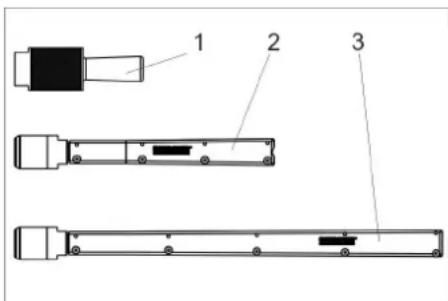
1 Round jet nozzle, short
2 Round jet nozzle, long
3 Round jet nozzle, extra long
→ Place the round jet nozzle on the threaded support of the jet pistol and tighten it by hand.
Flat jet nozzle
1 Diffuser
2 Union joint
3 Nozzle insert
The flat jet nozzle consists of a nozzle insert and a diffuser. Nozzle inserts with varying cross-sections are available as accessories.
→ Place the nozzle insert on the threaded support of the jet pistol and tighten it by hand.
→ Place the diffuser on the nozzle attachment.
→ Turn the diffuser in such a way that the flat jet is properly aligned with the jet pistol.
→ Tighten the union joint by hand.
Scrambler (accessory)
The scrambler crushes the dry ice pellets and is mounted between the jet pistol and the nozzle.
The alignment of the 4 holes plates in the scrambler indicates the degree of comminution.
Select the degree of comminution:
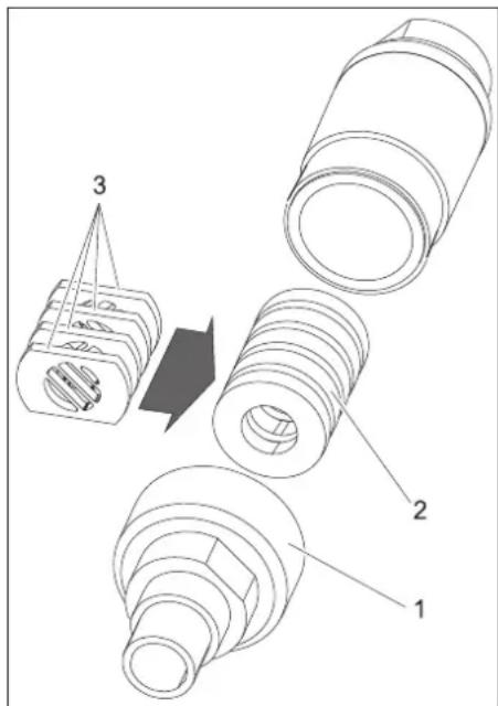
1 Screw connections
2 Magazine
3 Hole plate
→ Remove the screw connection.
→ Remove the magazine with hole plates.
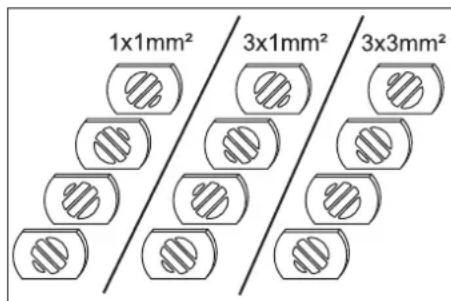
→ Align the hole plates, as shown above, in the magazine (3 possibilities). The above specifications in the illustration refer to the size of the permeation openings.
→ Insert the magazine with hole plates into the scrambler.
→ Unscrew the screw connection and tighten it.
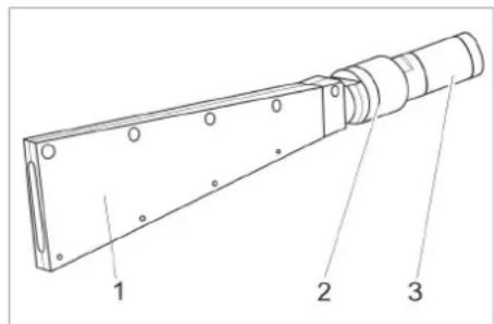
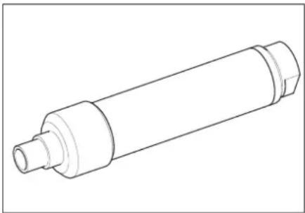
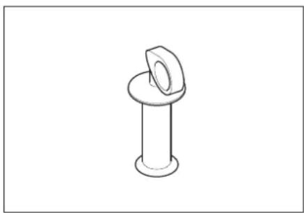
Nozzle extension (accessory)
An extension piece can be inserted between the jet pistol and the nozzle.
natural_image
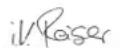
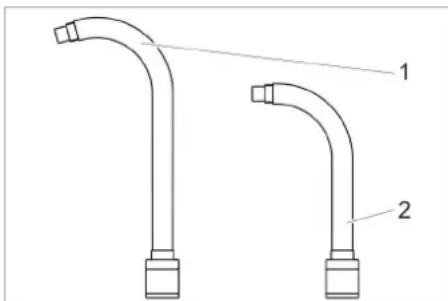
Technical line drawing of a cylindrical mechanical component with flanges and a central shaft (no text or symbols)Angle jet pipe (accessories)
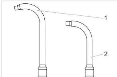
An angle jet pipe is installed between the jet gun and the nozzle.

1 Angle jet pipe 105°
2 Angle jet pipe 90°
⚠ Warning
Risk of injury. When the angle jet pipe is used, a torsional moment acts on the jet pistol in addition to the repulsion power. Hold the jet pistol tightly.
Start your work with low jet pressure and increase the jet pressure as necessary.
Handle (accessory)
The handle can be fastened on the extension piece.
natural_image
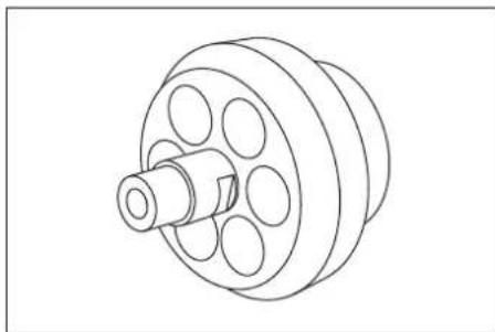
Simple line drawing of a bolt and nut (no text or symbols)Working light (accessory)
(only with Advanced jet pistol)
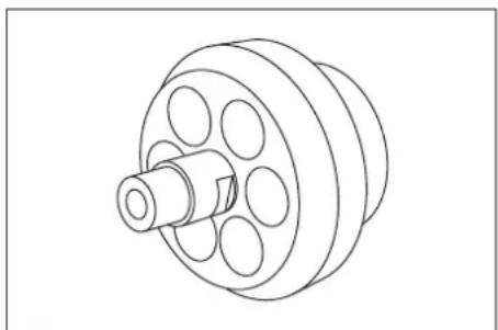
natural_image
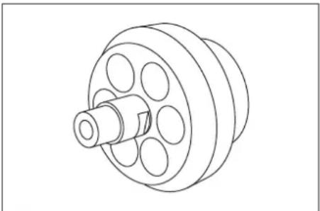
Technical line drawing of a mechanical component with a central shaft and multiple circular holes (no text or symbols)The working light is connected between the jet pistol and the nozzle. Switching on and switching off is described in the chapter "Operation/Basic Settings".
Connect compressed air supply
Note
For failure-free operation the compressed air must have a low moisture content. The compressed air must also be free from oil, dirt and foreign particles.
The compressor must at least be equipped with aftercooler, oil and water separator.
→ Close pressure relief valve.
→ Connect the compressed air inlet pipe to the compressed air connection point of the device.
The maximum permissible supply pressure of 1.6 MPa (16 bar) must not be exceeded.
Establish mains contact
⚠️Danger
Risk of electric shock.
The socket to be used must have been installed by an electrician and be compliant with IEC 60364-1.
The machine must have an FI fuse of type B, 30 mA.
Check the mains cables of the machine each time before using the machine to see that it is not damaged. Never operate a machine with damaged cables. Get the damaged cables replaced by an electrician.
The extension cord must be protected by IPX4 safety mechanism and the cables must at least be compliant with H 07 RN-F 3G1.5.
→ Insert the mains plug into the socket.
Operation
Filling dry ice
⚠️Danger
Risk of cold burns. Dry ice has a temperature of -79 °C. Never touch dry ice or cold parts of the machine without appropriate protection. Wear protective gloves and protective overalls.
→ Open the cover of the dry ice container.
→ Check the dry ice container for presence of foreign particles and condensate, remove them if found.
→ Fill dry ice pellets into the container.
Caution
Risk of damage to the device. Use only dry ice pellets as jet medium. The use of any other spray agent will lead to loss of warranty coverage.
→ Close the cover of the dry ice container.
Note
To avoid disturbances due to agglutinated dry ice pellets, it is useful to fully use up the contents of the dry ice container before adding fresh dry ice. If the machine is to remain idle for a longer time, operate the device until the dry ice container is empty or empty the container via the dry ice emptying function.
Settings
Note
The settings depend on the substances contained in the detergent and the type of dirt.
→ Release emergency-stop button by turning.
→ Set the appliance switch to "l".
→ Turn the keyswitch in a clockwise direction.
→ Increase/reduce the jet pressure by using the respective keys.
Note
The higher you set the jet pressure, so much greater (more agressive) will the cleaning effect be.
→ Increase/reduce the dry ice dosing by using the respective keys.
→ Turn the keyswitch counter-clockwise and remove the key.
The automatic closure of the key hole will prevent contamination during operation.
When the key is removed, the device is protected against changes to the settings and resetting the statistics values.
Operation
→ Carry out maintenance jobs "daily before starting work" (see section "Maintenance and Care").
⚠️Danger
Risk of injury on account of flying dry ice pellets. Do not direct the jet pistol on persons. Keep third persons away from the place of use and when the machine is being operated (by cording off the area). Do not touch/hold the nozzle opening or the dry ice jet when the machine is running. First stop the compressed air supply before disconnecting the jet gun from the spray agent hose and the spray agent hose from the device; remove all pressure from the system and then pull the plug out of the socket.
→ Cordon off the working area to prevent persons coming close to the machine when it is being operated.
⚠️Danger
Risk of suffocation on account of carbon dioxide. The dry ice pellets are made of solidified carbon dioxide. The carbon dioxide content in the air at the place where the machine is used will increase when the machine is running. Sufficiently ventilate the workstation and use a personal warning device or breathing apparatuses, if necessary.
Indication of high carbon dioxide concentration in the breathing air:
- 3...5%: headache, faster breathing.
- 7...10%: headache, nausea and perhaps even unconsciousness.
If any of these symptoms occur, please switch off the machine immediately and get a breath of fresh air; improve the ventilation before starting work again with the machine or use respirators.
Carbon dioxide accumulates in lower situated places. Prevent accumulation by means of active ventilation measures. Follow the safety specifications of the manufacturer of dry ice.
⚠️Danger
There is a danger because of dangerous to your health materials. If dust that is dangerous to your health can be generated, the appropriate safety measures will have to be taken prior to beginning work.
⚠Danger
Risk of explosion!
Do not work on light metals and iron-containing substances simultaneously.
If you alternate between working on light metals and iron-containing parts, the work area and the suction device must be cleaned between work cycles.
Danger due to dust explosion. If inflammable dusts are formed during work, accumulations of dust must be avoided. Regularly remove dust before critical amounts are accumulated.
→ Ensure adequate ventilation while working in closed rooms in order to keep the carbon dioxide concentration in the atmospheric air in the room below the danger level.
→ Attach the object to be cleaned if necessary.
⚠️Danger
Risk of injury on account of electro-static discharge; risk of damage to the electronic components. The object being cleaned can get charged electrically during the cleaning process. Provide suitable earthing for the object being cleaned and ensure that the earthing remains intact during the entire cleaning process.
⚠ Warning
Risk of injury on account of tripping and falling.
Lay spray agent hose and control line in a way that they do not pose a risk of stumbling during work.
Caution
Risk of damage by foreign objects falling into the dry ice container. Keep cover of the dry ice container closed during operation.
→ Connect the electrically conductive earth wire to the object to be cleaned or earth the object to be cleaned in another way.
→ Wear safety gear, safety gloves, close fitting safety goggles and ear-protection.
→ Switch on the compressed air supply.
→ Release emergency-stop button by turning.
→ Set the operating type for the compressed air jet to "1" or dry ice jet to "2" on the operating type switch of the jet pistol.
→ Choose a safe place to stand, assume a secure body stance to avoid being thrown off-balance by the recoil pressure of the jet pistol.
In order to prevent the sudden recoil, a gradual increase of the jet pressure can be set up (see "Operation/Basic Setting", menu item "soft start").
→ Press in the safety knob of the jet pistol.
→ Activate the dry ice jet by pressing the trigger of the jet pistol and carry out the cleaning operation.
Note
When using the Advanced jet pistol, the dosing of dry ice pellets can be switched on or off via the dry ice dosing on/off key on the jet pistol. When the dosing is turned off, the key illuminates red, the display shows "ice off".
Moreover, when the Advanced jet pistol is used, the jet pressure and the dry ice quantity can be adjusted on the jet pistol.
Caution
Risk of damage to the dosing equipment on account of dirt. Keep the lid of the dry ice container closed during the spraying operation to prevent sprayed off dirt from entering it.
Switch-off in case of emergency
→ Release the trigger of the jet pistol.
→ Press emergency-stop button.
The dry ice dosing is topped and the air flow from the nozzle is interrupted.
→ Interrupt the compressed air supply.
Switching on after emergency-stop
→ Release emergency-stop button by turning.
Interrupting operation
→ Release the trigger of the jet pistol.
→ During breaks in operation, you can insert the jet pistol on the holder on the machine.
Note
During longer service interruptions, the dry ice pellets can agglutinate in the dry ice container. As far as possible, do not interrupt operations for more than 20 minutes. In case of extended interruptions, empty the dry ice container.
Drain off the condensate.
A water separator cleans the compressed air flowing to the device. This collects condensate in the water separator, that needs to be drained once in a while.
→ Place the collection trough under the condensate drain screw.
→ Open the pressure relief valve slowly and wait until the condensate has been drained from the device.
Note
Please dispose of condensate in an environmentally friendly manner.
Statistics functions
Retrieving values
→ Set the appliance switch to "I".
→ Press the Statistics key briefly to display the operating duration.
t: Operation duration since the last reset.
T: Total operating duration.
→ Press the Statistics key briefly to display the processed dry ice amount. m: Dry ice volume since the last reset. M: Total dry ice volume.
→ Press the Statistics key briefly to display the average dry ice consumption. q: Average dry ice consumption since the last reset. Q: Average total dry ice consumption.
Reset values
→ Turn the keyswitch in a clockwise direction.
→ Press the statistics key for 4 seconds.
Note
The total values cannot be erased.
Basic settings
→ Press the keys to increase and decrease the jet pressure at the same time and hold them, turn the keyswitch clockwise.
In the operating mode basic settings, the keys have the following functions:
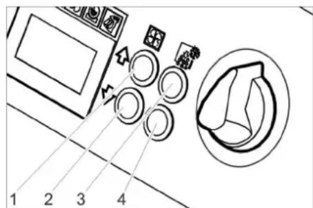
1 Increase value
2 Decrease value
3 Menu point to the top
4 Menu point to the bottom
| Menu point | Setting range | Description |
| Soft start | 0, 1, 2, 3, 4, 5 seconds | Soft start, duration until the selected jet pressure is reached |
| T_Dump | 1, 2, 3, 4, 5 minutes | Duration of the dry ice emptying process |
| Language | metric, imperial | Measurement units metric: kg/h, MPa imperial: lbs, psi |
| Lighting | ON/OFF Switch the nozzle lighting (option) on/off | |
| Demo mode | ON/OFF Demo mode: The operation is simulated, compressed air and dry ice dispensing is locked. | |
Finish the basic settings
→ Turn the keyswitch counter-clockwise.
Shutting down
⚠️Danger
Risk of cold burns. Dry ice has a temperature of -79 °C. Never touch dry ice or cold parts of the machine without appropriate protection. Wear protective gloves and protective overalls.
⚠️Danger
Risk of injury on account of flying dry ice pellets. Do not direct the jet pistol on persons. Keep third persons away from the place of use and when the machine is being operated (by cording off the area).
→ Close the compressed air supply.
→ Place the collection trough under the condensate drain screw.
→ Open the pressure relief valve slowly and wait until the condensate and the compressed air have been drained from the device.
→ Place the collection trough under the dry ice exit.
→ Press the key to empty the dry ice and wait until the dry ice container is empty. The dry ice emptying stops after the preset time has elapsed (see "Basic Settings").
If needed, press the key to empty the dry ice container several times.
Note
Please dispose of condensate in an environmentally friendly manner.
→ Set the appliance switch to "0/OFF".
→ Disconnect the machine from the compressed air inlet.
→ Disconnect the main plug from the socket.
→ Clean and roll up the grounding rope.
→ Dispose of blasting debris according to applicable regulations.
Transport
⚠️Danger
Risk of accident on account of dry ice residue in the device. Remove all traces of dry ice before transporting the device in closed vehicle; otherwise there is a risk of carbon dioxide suffocation to the co-passengers.
→ Carry out all the steps listed in the chapter "Shut down" before transporting the device.
→ Mount the appliance on the transport vehicle.
→ Lock the breaks of the steering rollers.
→ Fasten the device to the vehicle using fastening belts.
Storage
Caution
Risk of injury and damage! Note the weight of the appliance in case of storage. This appliance must only be stored in interior rooms.
Maintenance and care
Maintenance instructions
The bases of a safe operating of the equipment is the regularly maintenance according to the following maintenance plan. Use exclusively original parts of the manufacturer or those parts recommended by him like
- parts and wearing parts,
- accessories parts,
– operating materials, - cleaning agents.
DANGER
Risk of accident while working on the appliance. Carry out all the steps described in the chapter "Shut down" before starting anhy work on the device.
⚠️Danger
Risk of cold burns on account of dry ice or cold parts of the machine. While working on the machine, wear appropriate safety gear for protection against cold or remove dry ice and let the machine heat up.
⚠️Danger
Danger arising from volumetric expansion and cryogenic burn.
Never put dry ice in your mouth.
Caution
Risk of damage. Do not use solvents, petrol or oil-based cleaners to clean the jet pistol.
Maintenance contract
In order to guarantee a reliable operation of the equipment, we success, you signed a maintenance agreement. Please refer to your local Kärcher service department.
Maintenance schedule
Daily before starting operations
→ Check the spray agent hose for damages, bends and other damages. Soft areas in the hose indicate wear on the inner side of the hose. Replace the defective or worn out hose with a new hose.
→ Check electrical cable and plug for damages. Get defective parts replaced by Customer Service.
Every 100 operating hours
→ Check couplings of the spray agent hose, on the device, at the jet pistol for damages or wear and tear. Get Customer Service to replace the defective hose, defective couplings on the device or jet pistol.
→ Check dosing equipment for damages or leaks. If you find any damages/leaks, inform Customer Service.
→ Check the attachment caps of the rear wheels for proper seating.
Every 500 hours or once a year
→ Get the device checked by Customer Service.
Every 2 years
→ Replace the spray agent hose at least once in 2 years.
Opening the device
The side panels of the device must be removed to access the device for maintenance jobs:
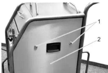
1 Snap closure
2 Side panels
→ Open the snap closures in the anticlockwise direction.
→ Remove side panel.
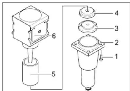
Maintenance Works
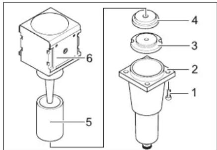
Replace the filter insert in the water separator.
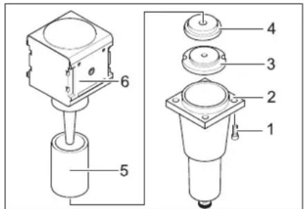
1 Screw
2 Lower part
3 Nut
4 Disc
5 Filter inlay
6 Upper section
→ Loosen 4 screws.
→ Remove the lower part.
→ Unscrew the nut.
→ Remove the disc.
→ Remove the filter inlay and replace it with a new filter inlay.
→ Reassemble the water separator in the reverse sequence.
Tests
According to the specifications of BDV D 26, the following tests must be conducted by a technical expert. The results of the tests must be documented in a test report. The device operator must carefully store the test report until the next test.
After a working break of more than one year
→ Check the device to see that it is in a proper condition and is functioning well.
After changing the installation site
→ Check the device to see that it is in a proper condition, is functioning well and has been installed properly.
The operational safety of the device can get hampered on account of maintenance jobs or any modifications that have been done.
→ Check the device to see that it is in a proper condition, is functioning well and has been installed properly.
Troubleshooting
DANGER
Risk of accident while working on the appliance. Carry out all the steps described in the chapter "Shut down" before starting anhy work on the device.
⚠️Danger
Risk of cold burns on account of dry ice or cold parts of the machine. While working on the machine, wear appropriate safety gear for protection against cold or remove dry ice and let the machine heat up.
⚠️Danger
Danger arising from volumetric expansion and cryogenic burn.
Faults with display
| Display Indicator lamp (KL) Possible cause Remedy By whom | ||||
| E001 KL control voltage glows red | Control voltage too low Turn off | the appliance, wait briefly, turn on the appli-ance once again.Have the socket checked.If this error recurs, please contact the Kärcher custom-er service department | Operator | |
| E002 KL emergency stop glows red | Emergency-stop button has been pressed. | Release emergency-stop button by turning. Operator | ||
| E003 KL compressed air glows red | Pressure of the compressed air supply too low | Increase the pressure.Turn off the appliance, wait briefly, turn on the appli-ance once again. | Operator | |
| E004 KL dosing glows red Interfe | erence in the dosing Turn off the | appliance, wait briefly, turn on the appli-ance once again.If this error recurs, please contact the Kärcher custom-er service department | Operator | |
| E005 KL jet pistol glows red | Connection between the device and the jet pistol is faulty. | Check for correct connection of the couplings in the control line.Check control cable for damages. | Operator | |
| E006 KL jet pistol glows red | Short in jet pistol or control cable | Replace the jet pistol or the jet hose with a control ca-ble. | Operator | |
| E007 KL compressed air glows red | Fault in the compressed air reg-ulator valve | Call Customer Service. Operator | ||
| E008 KL jet pistol glows orange | The trigger of the jet pistol was activated during the switch-on process or the releasing of the emergency stop key. | Release the trigger of the jet pistol. Operator | ||
Faults without display on the console
| Fault Possible cause | Remedy By whom | ||
| No display inspite of power switch in position 1 | Mains Plug not connected to the socket. Insert the mains plug into a socket. Operator | ||
| Fuse F1 blown Remove the side panel and unlock the fuse F1 by pressing on it. | Operator | ||
| No compressed air jet despite the trigger being drawn | Compressed air supply has too little pressure | Check pressure level. Operator | |
| Jet pressure is set too low Set the jet pressure to a higher level. Operator | |||
| Power supply has been interrupted Check power supply. Indicator lamp "Device on" must glow green. | Operator | ||
| Emergency-stop button has been pressed. Release emergency-stop button by turning. Indicator lamp "Device on" must glow green. | Operator | ||
| Control cable not connected properly Check connection between control cable and the jet pistol and between the control cable and the device. | Operator | ||
| Control cable is defective Replace spray agent hose. Operator | |||
| Compressed air jet is too weak | Jet pressure is set too low Set the jet pressure to a higher level. Operator | ||
| Compressed air supply has too little pressure or the compressor output is low. | Check pressure and output. | Operator | |
| The filter insert in the water separator is plugged. | Replace the filter inlay in the water separator. | Operator | |
| Spray agent hose or jet pistol is blocked | Let the spray agent hose and jet pistol come to room temperature and remove the blocking. Increase working pressure and / or reduce the dry ice dosing. | Operator | |
| No dry ice pellets in the compressed air jet | Dry ice dosing switched off (with jet pistol Advanced only), "Dry ice dosing on/off" button on the jet pistol illuminates red, display shows "Ice off". | Press the dry ice dosing key on the Advanced jet pistol. | Operator |
| Dry ice container is empty | Refill the dry ice container | Operator | |
| Dry ice has melted | Empty the dry ice container and refill it with fresh dry ice pellets. | Operator | |
| Vibrator on the dry ice container is not working | Call Customer Service. | Operator | |
| Drive motor of the dosing equipment is overloaded | Let the dosing thaw | Operator | |
| Compressed air is exiting into the dry ice container | Clean the pressure balance channel in the dosing equipment. | Customer Service | |
| Dosing disc in the dosing unit is defective | Replace the dosing disc. | Customer Service | |
Technical specifications
| Electrical connection | ||
| Voltage V 220...240 | ||
| Current type 1~ | ||
| Frequency Hz 50 | ||
| Connected load kW 0,6 | ||
| Protective class IPX4 | ||
| FI safety switch delta I in A 0,03 | ||
| Leakage current, typ. mA 7,5 | ||
| Compressed air | ||
| Nominal width of hose Inch 3/4 | ||
| Pressure supply (max.) MPa (bar) 1,6 (16) | ||
| Pressure supply (min.) | MPa (bar) 0,2 (2) | |
| Compressed air consumption | m3/min | 2...12 |
| Quality of compressed air | dry, oil-free | |
| Performance data | ||
| Jet pressure (max.) | MPa (bar) 1,6 (16) | |
| Diameter of dry ice pellets (max.) | mm | 3 |
| Dry ice consumption | kg/h 30...120 | |
| Dimensions | ||
| Contents of dry ice container | kg | 40 |
| Width | mm | 716 |
| Depth | mm | 850 |
| Height | mm | 1102 |
| Weight with accessories | kg | 101,5 |
| Weight, operational, with filled dry ice container | kg | 140 |
| Weight of the jet equipment (spray agent hose, spray gun, tool case) | kg | 10 |
| Tyre pressure (max.) | MPa (bar) 0,2 (2) | |
| Recoil force of hand spray gun (max.) | N | 100 |
| Torque of jet pistol (max.), only with angled nozzle | N | 40 |
| Sound pressure level L_pA | dB(A) | 114 |
| Sound power level L_WA | dB(A) | 136 |
| Uncertainty K | dB(A) | 5 |
| Machine vibrations | ||
| Jet pistol | m/s2 | 1,2 |
| Hose for spraying agent | m/s2 | 1,2 |
Accessories
Protective clothing
Full view protective goggles, anti-condensation, part no.: 6.321-208.0
Cold protection gloves with anti-slip profile, category III as per EN 511, part no.: 6.321-210.0
Ear protection with headgear, part no.: 6.321-207.0
Jet equipment
Round jet nozzle, L, long
Part no.: 4.574-019.0
Round jet nozzle, L, extra long
Part no.: 4.574-016.0
Round jet nozzle, M, long
Part no.: 4.574-018.0
Round jet nozzle, M, short
Part no.: 4.130-418.0
Round jet nozzle, L, short
Part no.: 4.130-419.0
Flat jet nozzle
Part no.: 4.130-423.0
Flat jet nozzle insert, M, 6 mm
Part no.: 4.130-421.0
Flat jet nozzle insert, L, 8 mm
Part no.: 4.130-420.0
Flat jet nozzle insert, XL, 10 mm
Part no.: 4.130-422.0
Angle jet pipe 90°
Part no.: 4.321-203.0
Angle jet pipe 105°
Part no.: 4.321-204.0
Nozzle extension, 300 mm long
Part no.: 4.130-417.0
Handle
Part no.: 6.321-206.0
Scrambler
Part no.: 4.110-015.0
Working light
Part no.: 2.815-422.0
Protective hose for jet pipe, plastic, 100 m
Part no.: 6.667-214.0
Warranty
The warranty terms published by our competent sales company are applicable in each country. We will repair potential failures of your appliance within the warranty period free of charge, provided that such failure is caused by faulty material or defects in fabrication. In the event of a warranty claim please contact your dealer or the nearest authorized Customer Service center. Please submit the proof of purchase.
EU Declaration of Conformity
We hereby declare that the machine described below complies with the relevant basic safety and health requirements of the EU Directives, both in its basic design and construction as well as in the version put into circulation by us. This declaration shall cease to be valid if the machine is modified without our prior approval.
Product: Dry ice jet unit
Type: 1.574-xxx
Relevant EU Directives
2011/65/EU
2006/42/EC (+2009/127/EC)
2014/30/EU
2009/125/EG + 2009/1781
Applied harmonized standards
EN 55014-1: 2017 + A11: 2020
EN 55014-2: 2015
EN 60204-1
EN 61000-3-2: 2014
EN 61000-3-3: 2013
EN IEC 63000: 2018
EN 62233: 2008
Applied national standards
GS-STE-13 (based on it)
The undersigned act on behalf and under the power of attorney of the company management.

Chairman of the Board of Management
Director Regulatory Affairs & Certification
Documentation supervisor:
S. Reiser
Alfred Kärcher SE & Co. KG
71364 Winnenden (Germany)
Tel.: +49 7195 14-0
Fax: +49 7195 14-2212
Winnenden, 2021/02/01
Declaration of Conformity
We hereby declare that the product described below complies with the relevant provisions of the following UK Regulations, both in its basic design and construction as well as in the version put into circulation by us. This declaration shall cease to be valid if the product is modified without our prior approval.
Product: Dry ice jet unit
Type: 1.574-xxx
Currently applicable UK Regulations
S.I. 2012/3032 (as amended)
S.I. 2008/1597 (as amended)
S.I. 2016/1091 (as amended)
2009/125/EC + 2009/1781
Applied designated standards
EN 55014-1: 2017 + A11: 2020
EN 55014-2: 2015
EN 60204-1
EN 61000-3-2: 2014
EN 61000-3-3: 2013
EN IEC 63000: 2018
EN 62233: 2008
Applied national standards
GS-STE-13 (based on it)
The undersigned act on behalf and under the power of attorney of the company management.

Chairman of the Board of Management

Director Regulatory Affairs & Certification
Documentation supervisor:
S. Reiser
Alfred Kärcher SE & Co. KG
71364 Winnenden (Germany)
Tel.: +49 7195 14-0
Fax: +49 7195 14-2212
Winnenden, 2021/02/01
www.kaercher.com/REACH
natural_image
Collection of symbolic icons including a lightning bolt, human figures, a dog, a battery, and a warning sign (no text or labels)⚠️Danger
natural_image
Line drawing of a cylindrical mechanical component with flanges and a central shaft (no text or symbols)natural_image
Simple line drawing of a bolt and nut (no text or symbols)natural_image
Technical line drawing of a mechanical component with a central shaft and multiple circular holes (no text or symbols)2006/42/CE (+2009/127/CE)
2014/30/UE
2009/125/EG + 2009/1781

Chairman of the Board of Management
S. Reiser
Director Regulatory Affairs & Certification
Responsable de la documentation : S. Reiser
Alfred Kärcher SE & Co. KG
71364 Winnenden (Germany)
Tel.: +49 7195 14-0
Fax: +49 7195 14-2212
Winnenden, 2021/02/01
www.kaercher.com/REACH
Norme di sicurezza
⚠️ Pericolo
1 Ugello
natural_image
Technical line drawing of a cylindrical mechanical component with flanges and a central shaft (no text or symbols)natural_image
Line drawing of a mechanical bolt with a flanged cap (no text or symbols)natural_image
Technical line drawing of a mechanical pulley or wheel assembly (no text or symbols)1 Vite
2 Parte inferiore
3 Dado
4 Disco
5 Inserto filtro
6 Parte superiore

Chairman of the Board of Management
Director Regulatory Affairs & Certification
71364 Winnenden (Germany)
Tel.: +49 7195 14-0
Fax: +49 7195 14-2212
Winnenden, 2021/02/01
www.kaercher.com/REACH
natural_image
Pure graphical symbols representing surveillance, human figures, animals, and devices without any text or labels⚠ Gevaar
1 Sluiting
2 Handgreep
3 Ontgrendeling
Koffer openen
natural_image
Line drawing of a cylindrical mechanical component with flanges and a central shaft (no text or symbols)Hoekstraalpijp (accessoires)
natural_image
Simple line drawing of a bolt and nut (no text or symbols)Werkverlichting (accessoires)
natural_image
Technical line drawing of a mechanical pulley or wheel assembly (no text or symbols)1 Snelsuiting
2 Zijbekleding
H. Jenner
Chairman of the Board of Management

S. Reiser
Director Regulatory Affairs & Certification
71364 Winnenden (Germany)
Tel.: +49 7195 14-0
Fax: +49 7195 14-2212
Winnenden, 2021/02/01
www.kaercher.com/REACH
natural_image
Pure graphical symbols representing surveillance, human figures, a dog, and devices without any text or labels⚠Peligro
1 Cierre
2 Asa de transporte
3 Desbloqueo
Abrir la maleta
1 Boquilla de chorro redondo, corta
2 Boquilla de chorro redondo, larga
3 Boquilla de chorro redondo, extra larga
natural_image
Line drawing of a cylindrical mechanical component with flanges and a central shaft (no text or symbols)natural_image
Technical line drawing of a bolt and nut assembly (no text or symbols)natural_image
Technical line drawing of a mechanical component with a central shaft and multiple circular holes (no text or symbols)1 Tornillo
2 Parte inferior
3 Tuerca
4 Arandela
5 Cartucho filtrante
6 Parte superior
2006/42/CE (+2009/127/CE)
2014/30/UE
2009/125/EG + 2009/1781
Chairman of the Board of Management
S. Reiser
Director Regulatory Affairs & Certification
71364 Winnenden (Germany)
Tel.: +49 7195 14-0
Fax: +49 7195 14-2212
Winnenden, 2021/02/01
www.kaercher.com/REACH
Avisos de segurança
natural_image
Pure graphical symbols representing surveillance, human figures, a dog, and other objects without any text or labels⚠️Perigo
1 Bocal de jacto redondo, curto
2 Bocal de jacto redondo, comprido
3 Bocal de jacto redondo, extra comprido
natural_image
Line drawing of a cylindrical mechanical component with flanges and a central shaft (no text or symbols)natural_image
Simple line drawing of a bolt and nut (no text or symbols)natural_image
Technical line drawing of a mechanical pulley or wheel assembly (no text or symbols)1 Fecho rápido
2 Revestimento lateral
1 Parafuso
2 Parte inferior
3 Porca
4 Anilha
5 Elemento filtrante
6 Parte superior
2006/42/CE (+2009/127/CE)
2014/30/UE
2009/125/EG + 2009/1781

Chairman of the Board of Management
Director Regulatory Affairs & Certification
71364 Winnenden (Germany)
Tel.: +49 7195 14-0
Fax: +49 7195 14-2212
Winnenden, 2021/02/01
www.kaercher.com/REACH
natural_image
Pure graphical symbols representing surveillance, human figures, a dog, and a device (no text or labels)Risiko
1 Rundstråledyse, kort
2 Rundstråledyse, lang
3 Rundstråledyse, ekstra lang
natural_image
Technical line drawing of a cylindrical mechanical component with flanges and a central shaft (no text or symbols)natural_image
Simple line drawing of a bolt and nut (no text or symbols)natural_image
Technical line drawing of a mechanical component with a central shaft and multiple circular holes (no text or symbols)1 Hurtigläs
2 Sideskærme
→ Åbn hurtiglåsene imod uret.
1 Skrue
2 Bund
3 Møtrik
4 Skive
5 Filterindsats
6 Top
Dele-nr.: 4.574-018.0
Dele-nr.: 4.130-423.0
Fladstråledyse-adapter, M, 6 mm
Dele-nr.: 4.130-421.0
Fladstråledyse-adapter, L, 8mm
Dele-nr.: 4.130-420.0
Fladstråledyse-adapter, XL, 10 mm
Dele-nr.: 4.130-422.0
Dele-nr.: 6.667-214.0
Garanti EU-overen
2006/42/EF (+2009/127/EF)
2014/30/EU
2009/125/EG + 2009/1781

Chairman of the Board of Management
Director Regulatory Affairs & Certification
71364 Winnenden (Germany)
Tel.: +49 7195 14-0
Fax: +49 7195 14-2212
Winnenden, 2021/02/01
www.kaercher.com/REACH
natural_image
Pure graphical symbols representing surveillance, human figures, a dog, and equipment (no text or labels)⚠️Fare!
1 Dyse
2 Strålepistol
3 Kobling strålemiddelslange
4 Kobling styreledning
5 Sikringshendel
6 Avtrekkerhendel
7 Driftstypebryter
1 Rundstråledyse, kort
2 Rundstråledyse, lang
3 Rundstråledyse, ekstra lang
1 Skrueforbindelse
2 Magasin
3 Hullplate
natural_image
Technical line drawing of a cylindrical mechanical component with flanges and a central shaft (no text or symbols)natural_image
Line drawing of a mechanical bolt with a flanged cap (no text or symbols)natural_image
Technical line drawing of a mechanical component with a central shaft and multiple circular holes (no text or symbols)1 Skrue
2 Underdel
3 Mutter
4 Skive
5 Filterinnsats
6 Overdel
→ Skru ut 4 skruer.
→ Ta av underdelen.
→ Skru ut mutter.
→ Ta av skive.
Winnenden, 2021/02/01
www.kaercher.com/REACH
natural_image
Pure graphical symbols representing surveillance, human figures, a dog, and equipment (no text or labels)⚠️Fara
1 Skruvkoppling
2 Magasin
3 Hålskiva
natural_image
Line drawing of a cylindrical mechanical component with flanges and a central shaft (no text or symbols)natural_image
Simple line drawing of a bolt and nut (no text or symbols)natural_image
Technical line drawing of a mechanical pulley or wheel assembly (no text or symbols)1 Snabbförslutning
2 Sidoskydd
71364 Winnenden (Germany)
Tel.: +49 7195 14-0
Fax: +49 7195 14-2212
Winnenden, 2021/02/01
www.kaercher.com/REACH
Turvaohjeet
natural_image
Pure graphical symbols representing surveillance, human figures, a dog, and a device (no text or labels)⚠ Vaara
1 Lukitus
2 Kantokahva
3 Lukituksen poisto
Laukun avaaminen
natural_image
Technical line drawing of a cylindrical mechanical component with flanges and a central shaft (no text or symbols)Kulmaruiskuputki (varuste)
1 Kulmaruiskuputki 105°
2 Kulmaruiskuputki 90°
Varoitus
natural_image
Simple line drawing of a bolt and nut (no text or symbols)natural_image
Technical line drawing of a mechanical component with a central shaft and multiple circular holes (no text or symbols)1 Pikakiinnitin
2 Sivuverhous

Chairman of the Board of Management
S. Reiser
Director Regulatory Affairs & Certification
71364 Winnenden (Germany)
Tel.: +49 7195 14-0
Fax: +49 7195 14-2212
Winnenden, 2021/02/01
natural_image
Pure graphical symbols representing surveillance, human figures, a dog, and a device (no text or labels)⚠️Κίνδυνος
natural_image
Line drawing of a cylindrical mechanical component with flanges and a central shaft (no text or symbols)natural_image
Simple line drawing of a bolt with a flange and cap (no text or symbols)natural_image
Technical line drawing of a mechanical pulley or wheel assembly (no text or symbols)
H. Jenner
Chairman of the Board of Management

S. Reiser
Director Regulatory Affairs & Certification
71364 Winnenden (Germany)
Tel.: +49 7195 14-0
Fax: +49 7195 14-2212
Winnenden, 2021/02/01
www.kaercher.com/REACH
Güvenlik uyarıları
Tehlike
natural_image
Line drawing of a cylindrical mechanical component with flanges and a central shaft (no text or symbols)Açılı püskürtme borusu (aksesuar)
natural_image
Technical line drawing of two curved pipe fittings with labeled parts (no text or symbols present)natural_image
Simple line drawing of a bolt and nut (no text or symbols)natural_image
Technical line drawing of a mechanical component with a central shaft and multiple circular holes (no text or symbols)1 Mandal
2 Yan kaplama

Chairman of the Board of Management
S. Reiser
Director Regulatory Affairs & Certification
71364 Winnenden (Germany)
Tel.: +49 7195 14-0
Fax: +49 7195 14-2212
Winnenden, 2021/02/01

www.kaercher.com/REACH
⚠️ Опасность
1 Блокировка
natural_image
Technical line drawing of a cylindrical mechanical component with flanges and a central shaft (no text or symbols)natural_image
Line drawing of a mechanical component with a flanged top and cylindrical base (no text or symbols)natural_image
Technical line drawing of a mechanical component with a central shaft and multiple circular holes (no text or symbols)
Chairman of the Board of Management

Director Regulatory Affairs & Certification
71364 Winnenden (Germany)
Tel.: +49 7195 14-0
Fax: +49 7195 14-2212
Winnenden, 2021/02/01
www.kaercher.com/REACH
Biztonsági tanácsok
⚠ Veszély
natural_image
Line drawing of a cylindrical mechanical component with flanges and a central shaft (no text or symbols)natural_image
Line drawing of a mechanical bolt with a flanged cap (no text or symbols)natural_image
Technical line drawing of a mechanical component with a central shaft and multiple circular holes (no text or symbols)
H. Jenner
Chairman of the Board of Management
S. Reiser
Director Regulatory Affairs & Certification
71364 Winnenden (Germany)
Tel.: +49 7195 14-0
Fax: +49 7195 14-2212
Winnenden, 2021/02/01
www.kaercher.com/REACH
Bezpečnostní pokyny
⚠️Nebezpečí
natural_image
Line drawing of a cylindrical mechanical component with flanges and a central shaft (no text or symbols)natural_image
Technical line drawing of two curved pipe fittings with labeled parts (no text or symbols present)natural_image
Line drawing of a mechanical component with a flanged top and cylindrical base (no text or symbols)natural_image
Technical line drawing of a mechanical component with a central shaft and multiple circular holes (no text or symbols)2006/42/ES (+2009/127/ES)
2014/30/EU
2009/125/EG + 2009/1781
Chairman of the Board of Management

S. Reiser
Director Regulatory Affairs & Certification
71364 Winnenden (Germany)
Tel.: +49 7195 14-0
Fax: +49 7195 14-2212
Winnenden, 2021/02/01
www.kaercher.com/REACH
Varnostna navodila
⚠️ Nevarnost
1 Šoba
2 Brizgalna pištola
3 Spoj gibke cevi brizgalnega sredstva
4 Spoj krmilnega voda
5 Varovalo
6 Sprožilna ročica
7 Stikalo za način obratovanja
Položaj „1“: Curek stisnjenega zraka
Položaj „2“: Curek suhega ledu (stisnjeni zrak in kroglice suhega ledu)
Brizgalna pištola Advanced (Opcija)
1 Zapiralo
2 Nosilni ročaj
3 Deblokada
Odpiranje kovčka
natural_image
Technical line drawing of a cylindrical mechanical component with flanges (no text or symbols)Kotna brizgalna cev (pribor)
natural_image
Line drawing of a mechanical bolt with a flanged cap (no text or symbols)natural_image
Technical line drawing of a mechanical component with a central shaft and multiple circular holes (no text or symbols)1 Hitro zapiralo
2 Stranska obloga
→ Hitra zapirala odprite v nasprotni smeri urinega kazalca.
→ Snemite stransko oblogo.
Vzdrževanje
1 Vijak
2 Spodnji del
3 Matica
4 Kolut
5 Filtrni vložek
6 Zgornji del
→ Izvijte 4 vijake.
→ Snemite spodnji del.
→ Odvijte matice.
→ Odstranite kolut.
→ Snemite filtrni vložek in ga zamenjajte z novim filtrnim vložkom.
→ Vodni ločevalnik ponovno sestavite v obratnem vrstnem redu.
Pregledi
V skladu z BGV D 26 mora strokovnjak na napravi opraviti naslednje preglede. Rezultate pregleda je potrebno podati pisno v Potrdilu o pregledu. Potrdilo o pregledu mora upravljavec naprave shraniti do naslednjega pregleda.
2006/42/ES (+2009/127/ES)
2014/30/EU
2009/125/EG + 2009/1781
Chairman of the Board of Management Director Regulatory Affairs & Certification
71364 Winnenden (Germany)
Tel.: +49 7195 14-0
Fax: +49 7195 14-2212
Winnenden, 2021/02/01
www.kaercher.com/REACH
Niebezpieczeństwo
natural_image
Line drawing of a cylindrical mechanical component with flanges and a central shaft (no text or symbols)1 Lanca kątowa 105°
2 Lanca kątowa 90°
⚠Ostrzeżenie
natural_image
Simple line drawing of a bolt and nut (no text or symbols)natural_image
Technical line drawing of a mechanical component with a central shaft and multiple circular holes (no text or symbols)
Chairman of the Board of Management
S. Reiser
Director Regulatory Affairs & Certification
71364 Winnenden (Germany)
Tel.: +49 7195 14-0
Fax: +49 7195 14-2212
Winnenden, 2021/02/01
www.kaercher.com/REACH
Măsuri de siguranță
natural_image
Pure graphical symbols representing surveillance, human figures, a dog, and equipment (no text or labels)⚠ Pericol
Panou operator Ecran
1 Închizătoare
natural_image
Technical line drawing of a cylindrical mechanical component with flanges and a central shaft (no text or symbols)Lance unghiulară (accesoriu)
natural_image
Technical line drawing of two curved pipe fittings with labeled parts (no text or symbols present)natural_image
Simple line drawing of a bolt and nut (no text or symbols)natural_image
Technical line drawing of a mechanical component with a central shaft and multiple circular holes (no text or symbols)Directive UE respectate:
2011/65/EU
2006/42/CE (+2009/127/CE)
2014/30/UE
2009/125/EG + 2009/1781
Norme armonizate utilize:
EN 55014-1: 2017 + A11: 2020
EN 55014-2: 2015
EN 60204-1
EN 61000-3-2: 2014
EN 61000-3-3: 2013
EN IEC 63000: 2018
EN 62233: 2008
Chairman of the Board of Management
S. Reiser
Director Regulatory Affairs & Certification
71364 Winnenden (Germany)
Tel.: +49 7195 14-0
Fax: +49 7195 14-2212
Winnenden, 2021/02/01
www.kaercher.com/REACH
Bezpečnostné pokyny
⚠️Nebezpečenstvo
1 Kruhová dýza, krátka
2 Kruhová dýza, dlhá
3 Kruhová dýza, extra dlhá
natural_image
Line drawing of a cylindrical mechanical component with flanges and a central shaft (no text or symbols)natural_image
Simple line drawing of a bolt with a flanged cap (no text or symbols)natural_image
Technical line drawing of a mechanical pulley or wheel assembly (no text or symbols)1 Rýchlouzáver
2 Bočný plášť
2006/42/ES (+2009/127/ES)
2014/30/EU
2009/125/EG + 2009/1781
Uplatňované harmonizované normy:
EN 55014-1: 2017 + A11: 2020
EN 55014-2: 2015
EN 60204-1
EN 61000-3-2: 2014
EN 61000-3-3: 2013
EN IEC 63000: 2018
EN 62233: 2008

Chairman of the Board of Management
Director Regulatory Affairs & Certification
71364 Winnenden (Germany)
Tel.: +49 7195 14-0
Fax: +49 7195 14-2212
Winnenden, 2021/02/01
Prije prve uporabe Vašeg uređaja pročitajte ove originalne radne upute, postupajte prema njima i sačuvajte ih za kasniju uporabu ili za sljedećeg vlasnika.
Pregled sadržaja
www.kaercher.com/REACH
Sigurnosni napuci
natural_image
Pure graphical symbols representing surveillance, human figures, a dog, and devices without any text or labels⚠️ Opasnost
1 Mlaznica
2 Brizgaljka
3 Spojka crijeva za sredstvo za brizganje
1 Mlaznica
2 Brizgaljka
3 Poluga okidača
4 Sigurnosni gumb
5 Spojka crijeva za sredstvo za brizganje
1 Zatvarač
2 Rukohvat
3 Zapor
Otvaranje kovčega
1 Vijčani spoj
2 Spremnik
3 Rupičasta ploča
→ Odvijte vijčane spojeve.
→ Izvadite spremnik s rupičastim pločama.

→ Rupičaste ploče rasporedite u spremniku kao što je prikazano gore (3 mogućnosti). Mjera na slici se odnosi na veličinu propustnih otvora.
→ Spremnik sa rupičastim pločama stavi- te u Scrambler.
→ Navijte i zategnite vijčane spojeve.
Produžetak sapnice (pribor)
Između brizgaljke i sapnice može se staviti produžetak.

natural_image
Line drawing of a cylindrical mechanical component with flanges and a central shaft (no text or symbols)Koljenasta cijev za prskanje (pribor)
Koljenasta cijev za prskanje umeće se između prskalice i mlaznice.
1 Koljenasta cijev za prskanje 105°
2 Koljenasta cijev za prskanje 90°
⚠Upozorenje
natural_image
Simple line drawing of a bolt with a flange and cap (no text or symbols)Radno svjetlo (pribor)
(samo kod prskalica izvedbe Advanced)
natural_image
Technical line drawing of a mechanical pulley or wheel assembly (no text or symbols)1 Bravica
2 Bočna oplata
→ Otvorite bravice okretanjem ulijevo.
→ Skinite bočnu oplatu.
Radovi na održavanju
Zamijenite filtarski umetak u separatoru vode
1 Vijak
2 Donji dio
3 Matica
4 Pločica
5 Filtarski umetak
6 Gornji dio
→ Odvijte 4 vijka.
→ Skinite donji dio.
→ Odvijte maticu.
→ Skinite pločicu.
→ Filtarski umetak skinite i zamijenite novim filtarskim umetkom.
→ Separator vode ponovno sastavite obrnutim redoslijedom.
provjeravanje
2006/42/EZ (+2009/127/EZ)
2014/30/EU
2009/125/EG + 2009/1781

Chairman of the Board of Management
S. Reiser
Director Regulatory Affairs & Certification
Opunomoćeni za izradu dokumentacije: S. Reiser
Alfred Kärcher SE & Co. KG
71364 Winnenden (Germany)
Tel.: +49 7195 14-0
Fax: +49 7195 14-2212
Winnenden, 2021/02/01

Pre prve upotrebe Vašeg uređaja pročitajte ove originalno
www.kaercher.com/REACH
Sigurnosne napomene
Uređaj se smije koristiti samo od osoba, koje su pročitale upustvo za upotrebu i koji su je razumjeli. Moraju se uvažavati sve sigurnosne napomene.
→ Upustvo za upotrebu čuvati na taj način, tako da je korisniku dostupna u svakom trenutku.
Stepeni opasnosti
⚠️Opasnost
Ukazuje na neposredno preteću opasnost koja dovodi do teških telesnih povreda ili smrti.
⚠Upozorenje
Ukazuje na eventualno opasnu situaciju koja može dovesti do teških telesnih povreda ili smrti.
Oprez
Ukazuje na eventualno opasnu situaciju koja može dovesti do lakših telesnih povreda ili izazvati materijalnu štetu.
Simboli na aparatu
⚠️ Opasnost
Opasnost od povrede kroz leteće pelete suhog leda. Mlazni pištolj ne uperivati na osobe. Ostale osobe udaljiti od mjesta obavljana rada i udaljiti ih od mjesta dok je mašina u pogonu (npr. kroz ograničavanje). Tokom pogona na dirati pipu ili u Trockeneisstrahl.
⚠️ Opasnost
Opasnost od trovana kroz ugljen dioksid. Pelete suhog leda se sastoje od čvrstog ugljen dioksida. Kod pogona uređaja raste količina ugljen dioksida u zraku na radnom mestu. Radno mesto dovoljno izračiti, po potrebi koristiti uređaj za upozorenje osoblja. Znak visoke koncentracije ugljen dioksida u zraku:
- 3...5%: Glavobolja, visoka frekvencija disanja.
- 7...10%: Glavobolja, povraćanje i eventualno gubljenje svesti.
Kod pojave ovih naznaka uređaj odmah ugasiti i izaći na svež zrak, prije nastavka rada poboljšati mere prozračivanja ili koristiti uređaj za disanje.
1 Brizgaljka
2 Mlazni pištolj
3 Spojnica cijevi mlaznog sredstva
4 Spojnica voda upravljača
5 Sigurnosna poluga
6 Okidač
7 Prekidač za izbor načina rada
Položaj "1": Mlaz komprimovanog vazduha
Položaj "2": Mlaz suvog leda (komprimovani vazduh sa štapićima suvog leda)
1 Brizgaljka
2 Mlazni pištolj
3 Okidač
4 Sigurnosno dugme
5 Spojnica cijevi mlaznog sredstva
6 Spojnica voda upravljača
7 Tipka za doziranje suhog leda upaljeno / ugašeno
Svetli crveno kod ugašenov doziranja suhog leda
8 Povećati tipku za doziranje suhog leda.
9 Povećati tipku za mlazni pritisak.
1 Zatvarač
2 Ručka za nošenje
3 Bravica
Otvaranje kutije
→ Otvorite zatvarače.
→ Zakrenite poklopac prema dole.
Oprez
Opasnost od oštećenja, ne stavljajte teške predmete na otvoreni poklopac.
Odvajanje kutije od uređaja
→ Pritisnite bravice i skinite kutiju.
Postavljanje kutije na uređaj
→ Okrenite kutiju sa zatvaračima prema gore.
→ Jednu stranu kutije postavite na držač i uglavite.
→ Pritisnite kutiju uz uređaj i uglavite naspramni držač.
Stavljanje u pogon
⚠️ Opasnost
1 Zavrtni spoj
2 magazin
3 rupčasta ploča
natural_image
Line drawing of a cylindrical mechanical component with flanges and a central shaft (no text or symbols)Ugaona cev za prskanje (pribor)
Ugaona cev za prskanje postavlja se između prskalice i mlaznice.

natural_image
Simple line drawing of a bolt and nut (no text or symbols)natural_image
Technical line drawing of a mechanical pulley or wheel assembly (no text or symbols)Radno osvetljenje se montira između mlaznog pištolja i pipe. Paljenje i gašenje je opisano u poglavlju "Upravljanje/osnovne postavke".
1 Bravica
2 Bočna oplata
→ Otvorite bravice okretanjem ulevo.
→ Skinite bočnu oplatu.
Radovi na održavanju
Filter zameniti u rezaču vode
1 Zavrtanj
2 Donji deo
3 Navrtka
4 Pločica
5 Filter
6 Gornji deo
→ Odvijte 4 zavrtnja.
→ Skinuti donji deo.
→ Maticu odvrnuti.
→ Skinite zaštitnu kapicu.
→ Filter skinuti i zamenuti kroz novi filter.
→ Rezač vode ponovo pričvrstite obrnutim redosledom.
Ispitivanja
Po BGV D 26 ispitivanja koja slede na uređaju moraju biti izvedena od stručne osobe. Rezultati ispitivanja moraju biti zapisana u uverenju o ispitivanju. Uvrerenje o ispitivanju mora biti čuvano od strane pokretača uređaja sve do sledećeg ispitivanja.
Nakon prekida pogona dužeg od jedne godine
→ Uređaj pregledati na uredan statav i funkciju.
Nakon promene mesta rada
→ Uređaj pregledati na uredan sastav, funkciju i položaj.
Nakon radova na pokretanju ili promena koje bi mogle da utiu na sigurnost u radu.
→ Uređaj pregledati na uredan sastav, funkciju i položaj.
Otklanjanje smetnji
⚠️ Opasnost!
2006/42/EZ (+2009/127/EZ)
2014/30/EU
2009/125/EG + 2009/1781
71364 Winnenden (Germany)
Tel.: +49 7195 14-0
Fax: +49 7195 14-2212
Winnenden, 2021/02/01
www.kaercher.com/REACH
natural_image
Collection of symbolic icons including a lightning bolt, human figures, a dog, and a battery (no text or labels)⚠️ Опасност
1 Завинтване
2 Магазин
3 Перфорирана пластина
natural_image
Technical line drawing of a cylindrical mechanical component with flanges and a central shaft (no text or symbols)natural_image
Simple line drawing of a bolt and nut (no text or symbols)natural_image
Technical line drawing of a mechanical component with a central shaft and multiple circular holes (no text or symbols)
H. Jenner
Chairman of the Board of Management
S. Reiser
Director Regulatory Affairs & Certification
71364 Winnenden (Germany)
Tel.: +49 7195 14-0
Fax: +49 7195 14-2212
Winnenden, 2021/02/01
www.kaercher.com/REACH
natural_image
Pure graphical symbols representing surveillance, human figures, a dog, and equipment (no text or labels)⚠️Oht
→ Katkestage suruōhuga varustamine.
1 Ümardüüs, lühike
2 Ümardüüs, pikk
3 Ümardüüs, väga pikk
→ Pange ümardüüs joapüstoli keermetega tutsile ja keerake käega kinni.
Lamedüüs

natural_image
Line drawing of a cylindrical mechanical component with flanges and a central shaft (no text or symbols)Köver pritsetoru (tarvik)
1 Köver pritsetoru 105°
2 Köver pritsetoru 90°
△Hoiatus
natural_image
Simple line drawing of a bolt with a flanged cap (no text or symbols)natural_image
Technical line drawing of a mechanical pulley or wheel assembly (no text or symbols)→ Katkestage suruōhuga varustamine.
1 Kiirlukk
2 Küljepaneel
1 Kruvi
2 Alumine osa
3 Mutter
4 Seib
5 Filtripadrun
6 Ülemine osa

Chairman of the Board of Management
Director Regulatory Affairs & Certification
71364 Winnenden (Germany)
Tel.: +49 7195 14-0
Fax: +49 7195 14-2212
Winnenden, 2021/02/01
www.kaercher.com/REACH
Drošības norādījumi
⚠️Bīstami
1 Apalstrūklas sprausla, īsa
2 Apałstrūklas sprausla, gara
3 Apałstrūklas sprausla, īpaši gara
natural_image
Line drawing of a cylindrical mechanical component with flanges and a central shaft (no text or symbols)Lenka uzgalis (piederums)
Lenka uzgali ievieto starp strūklas pistoli un sprauslu.
1 Lenka uzgalis 105°
2 Lenka uzgalis 90°
⚠️Bridinājums
natural_image
Simple line drawing of a bolt and nut (no text or symbols)natural_image
Technical line drawing of a mechanical component with a central shaft and circular holes (no text or symbols)1 Aizslēgs
2 Sānu apšuvums
1 Skrūve
2 Apakšdaļa
3 Uzgrieznis
4 Paplāksne
5 Filtra ieliktnis
6 Augšdaļa

Chairman of the Board of Management

S. Reiser
Director Regulatory Affairs & Certification
71364 Winnenden (Germany)
Tel.: +49 7195 14-0
Fax: +49 7195 14-2212
Winnenden, 2021/02/01
www.kaercher.com/REACH
Saugos reikalavimai
natural_image
Pure graphical symbols representing human, animals, and equipment without any text or labels⚠️Pavojus
1 Fiksatorius
2 Rankena
3 Fiksatorius
Lagamino atidarymas
1 Apvalusis antgalis, trumpas
2 Apvalusis antgalis, ilgas
3 Apvalusis antgalis, ypač ilgas
natural_image
Line drawing of a cylindrical mechanical component with flanges and a central shaft (no text or symbols)Kampinis purškimo vamzdis (papildoma iranga)
natural_image
Technical line drawing of two curved pipe fittings with labeled parts (no text or symbols present)1 Kampinis purškimo vamzdis 105° 2 Kampinis purškimo vamzdis 90°
⚠️Ispéjimas
natural_image
Simple line drawing of a bolt and nut (no text or symbols)natural_image
Technical line drawing of a mechanical component with a central shaft and circular holes (no text or symbols)
Chairman of the Board of Management

Director Regulatory Affairs & Certification
71364 Winnenden (Germany)
Tel.: +49 7195 14-0
Fax: +49 7195 14-2212
Winnenden, 2021/02/01
⚠️Обережно!
natural_image
Technical line drawing of a cylindrical mechanical component with flanges and a central shaft (no text or symbols)natural_image
Technical line drawing of two curved pipe fittings with labeled parts (no text or symbols present)natural_image
Line drawing of a mechanical bolt with a flanged cap and cylindrical base (no text or symbols)natural_image
Technical line drawing of a mechanical component with a central shaft and multiple circular holes (no text or symbols)
Chairman of the Board of Management
Director Regulatory Affairs & Certification
71364 Winnenden (Germany)
Tel.: +49 7195 14-0
Fax: +49 7195 14-2212
Winnenden, 2021/02/01
www.kaercher.com/REACH
安全说明
危险
1 喷头
2 喷枪
3 喷射料软管连接器
4 控制导线连接
5 保护杆
6 扳机
7 运行模式开关
档位 “1”:压缩空气射流
1 封闭件
2 手柄
3 解锁装置
打开箱体
→ 打开搭扣。
→ 向下翻转盖子。
小心
损坏危险,不要在打开的盖子上放置重物。
将箱体从设备上分离。
→ 按压解锁装置并且取下箱体。
将箱体安装到设备上。
→ 用锁扣将箱体向上转动。
→ 将箱体的一侧放到支架上并且嵌入。
1 扩散器
2 锁紧螺母
3 喷嘴芯
1 螺旋连接
2 料仓
3 孔板
natural_image
Line drawing of a cylindrical mechanical component with flanges and a central shaft (no text or symbols)弯头喷管(配件)
在喷枪和喷嘴之间装入一根弯头喷管。
1 105° 弯头喷管
2 90° 弯头喷管
警告
natural_image
Line drawing of a mechanical bolt with a flanged cap (no text or symbols)工作照明 (配件)
(仅限 Advanced 喷枪)
natural_image
Technical line drawing of a mechanical pulley or wheel component (no text or symbols)1 快速封扣
2 侧板
1 螺丝
2 底部
natural_image
Black silhouette of a hand giving a thumbs-up gesture (no text or symbols)THANK YOU!
MERCI! DANKE! iGRACIAS!

Register your product and benefit from many advantages.
www.kaercher.com/welcome


Rate your product and tell us your opinion.
natural_image
Icon showing a gear and wrench inside a square frame (no text or symbols)www.kaercher.com/dealersearch
Alfred Kärcher SE & Co. KG
Alfred-Kärcher-Str. 28-40
71364 Winnenden (Germany)
Tel.: +49 7195 14-0
Fax: +49 7195 14-2212