
GTR 30 CE Professional - Drill BOSCH - Free user manual and instructions
Find the device manual for free GTR 30 CE Professional BOSCH in PDF.
User questions about GTR 30 CE Professional BOSCH
0 question about this device. Answer the ones you know or ask your own.
Ask a new question about this device
Download the instructions for your Drill in PDF format for free! Find your manual GTR 30 CE Professional - BOSCH and take your electronic device back in hand. On this page are published all the documents necessary for the use of your device. GTR 30 CE Professional by BOSCH.
USER MANUAL GTR 30 CE Professional BOSCH
DID DOKU-21601-404.Im Page 1 Wednesday, March 2, 2011 1:58 PM
Robert Bosch GmbH
Power Tools Division
70745 Leinfelden-Echterdingen
Germany
www.bosch-pt.com
2610016614(2010.10)O/257UNI

2610016614
GTR 30 CE Professional

BOSCH
de Originalbetriebsanleitung
en Original instruction
fr Notice originate
es Manual original
pt Manual original
It Istruzioni original
n Oarspronkelike
gebruksaanWjzng
O
SBrksanwngIgma no Oralal dafinstuk
1. Akuperaiset object
eInpoturuno onyyxphong
trOriginal Isletmet talmati
plnstrukcja orygina na
csPuvodni navod k pouzivani
skPovodny nayod na pouzitie
huEredeti hasznalatiutasitas
ruOprrnHaHbHoepykoBoAoCT
B0163xctxayataa
uOOPHARKBAHCTBYKUN
ekinyataun
nbnnnnne nnnnne
gOpHnAeNnEpyknH
Dr. Egbert Schneider Dr. Eckerhard Strotgen Senior Vice President Head of Product Engineering Certification
Paa
Robert Bosch GmbH, Power Tools Division D-70745 Leinfelden-Echterdingen 05.08.2010
Montage
General Power Tool SafetyWarnings
WARNING
Read all safety warnings and all instructions. Failure to follow
the warnings and instructions may result in electric shock, fire and/or serious injury.
Save all warnings and instructions for future reference.
The term "power tool" in the warnings refers to your mains-operated (corded) power tool or battery-operated (cordless) power tool.
1) Work area safety
a) Keep work area clean and well lit. Cluttered or dark areas invite accidents.
b) Do not operate power tools in explosive atmospheres, such as in the presence of flammable liquids, gases or dust. Power tools create sparks which may ignite the dust or fumes.
c) Keep children and bystanders away while operating a power tool. Distractions can cause you to lose control.
2) Electrical safety
a) Power tool plugs must match the outlet. Never modify the plug in any way. Do not use any adapter plugs with earthed (grounded) power tools. Unmodified plugs and matching outlets will reduce risk of electric shock.
b) Avoid body contact with earthed or grounded surfaces, such as pipes, radiators, ranges and refrigerators. There is an increased risk of electric shock if your body is earthed or grounded.
c) Do not expose power tools to rain or wet conditions. Water entering a power tool will increase the risk of electric shock.
d) Do not abuse the cord. Never use the cord for carrying, pulling or unplugging the power tool. Keep cord away from heat, oil, sharp edges and moving parts. Damaged or entangled cords increase the risk of electric shock.
e) When operating a power tool outdoors, use an extension cord suitable for outdoor use. Use of a cord suitable for outdoor use reduces the risk of electric shock.
f) If operating a power tool in a damp location is unavoidable, use a residual current device (RCD) protected supply. Use of an RCD reduces the risk of electric shock.
3) Personal safety
a) Stay alert, watch what you are doing and use common sense when operating a power tool. Do not use a power tool while you are tired or under the influence of drugs, alcohol or medication. A moment of inattention while operating power tools may result in serious personal injury.
b) Use personal protective equipment. Always wear eye protection. Protective equipment such as dust mask, non-skid safety shoes, hard hat, or hearing protection used for appropriate conditions will reduce personal injuries.
c) Prevent unintentional starting. Ensure the switch is in the off-position before connecting to power source and/or battery pack, picking up or carrying the tool. Carrying power tools with your finger on the switch or energising power tools that have the switch on invites accidents.
d) Remove any adjusting key or wrench before turning the power tool on. A wrench or a key left attached to a rotating part of the power tool may result in personal injury.
e) Do not overreach. Keep proper footing and balance at all times. This enables better control of the power tool in unexpected situations.
f) Dress properly. Do not wear loose clothing or jewellery. Keep your hair, clothing and gloves away from moving parts. Loose clothes, jewellery or long hair can be caught in moving parts.
16 | English
g) If devices are provided for the connection of dust extraction and collection facilities, ensure these are connected and properly used. Use of dust collection can reduce dust-related hazards.
4) Power tool use and care
a) Do not force the power tool. Use the correct power tool for your application. The correct power tool will do the job better and safer at the rate for which it was designed.
b) Do not use the power tool if the switch does not turn it on and off. Any power tool that cannot be controlled with the switch is dangerous and must be repaired.
c) Disconnect the plug from the power source and/or the battery pack from the power tool before making any adjustments, changing accessories, or storing power tools. Such preventive safety measures reduce the risk of starting the power tool accidentally.
d) Store idle power tools out of the reach of children and do not allow persons unfamiliar with the power tool or these instructions to operate the power tool. Power tools are dangerous in the hands of untrained users.
e) Maintain power tools. Check for misalignment or binding of moving parts, breakage of parts and any other condition that may affect the power tool's operation. If damaged, have the power tool repaired before use. Many accidents are caused by poorly maintained power tools.
f) Keep cutting tools sharp and clean. Properly maintained cutting tools with sharp cutting edges are less likely to bind and are easier to control.
g) Use the power tool, accessories and tool bits etc. in accordance with these instructions, taking into account the working conditions and the work to be performed. Use of the power tool for operations different from those intended could result in a hazardous situation.
5) Service
a) Have your power tool serviced by a qualified repair person using only identical replacement parts. This will ensure that the safety of the power tool is maintained.
SafetyWarnings for Routers
Hold power tool by insulated gripping surfaces, because the cutter may contact its own cord. Cutting a "live" wire may make exposed metal parts of the power tool "live" and shock the operator.
Use clamps or another practical way to secure and support the workpiece to a stable platform. Holding the work by your hand or against the body leaves it unstable and may lead to loss of control.
The allowable speed of the router bit must be at least as high as the maximum speed listed on the power tool. Accessories that rotate faster than permitted can be destroyed.
- Router bits or other accessories must fit exactly in the tool holder (collet) of your machine. Routing bits that do not fit precisely in the tool holder of the machine rotate irregularly, vibrate heavily and can lead to loss of control.
Apply the machine to the workpiece only when switched on. Otherwise there is danger of kickback when the cutting tool jams in the workpiece.
- Keep your hands out of the routing area and away from the router bit. Danger of injury.
- Never cut over metal objects, nails or screws. The router bit can become damaged and lead to increased vibrations.
Use appropriate detectors to determine if utility lines are hidden in the work area or call the local utility company for assistance. Contact with electric lines can lead to fire and electric shock. Damaging a gas line can lead to explosion. Penetrating a water line causes property damage or may cause an electric shock.
Do not use blunt or damaged router bits. Blunt or damaged router bits cause increased friction, can become jammed and lead to imbalance.
Do not keep combustible materials close to your workplace. When working tiles, hot material chips develop, which could start a fire.
Always wait until the machine has come to a complete stop before placing it down. The tool insert can jam and lead to loss of control over the power tool.
Products sold in GB only: Your product is fitted with a BS 1363/A approved electric plug with internal fuse (ASTA approved to BS 1362).
If the plug is not suitable for your socket outlets, it should be cut off and an appropriate plug fitted in its place by an authorised customer service agent. The replacement plug should have the same fuse rating as the original plug.
The severed plug must be disposed of to avoid a possible shock hazard and should never be inserted into a mains socket elsewhere.
Products sold in AUS and NZ only: Use a residual current device (RCD) with a rated residual current of 30mA or less.
Symbols
The following symbols can be important for the operation of your power tool. Please memorise the symbols and their meanings. The correct interpretation of the symbols helps you operate the power tool better and more secure.
Symbol Meaning

Wear safety goggles.

Wear ear protectors. Exposure to noise can cause hearing loss.
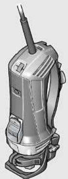
Wear a dust respirator.
Product Description and Specifications

Read all safety warnings and all instructions. Failure to follow the warnings and instructions may result in electric shock, fire and/or serious injury.
While reading the operating instructions, unfold the graphics page for the machine and leave it open.
Intended Use
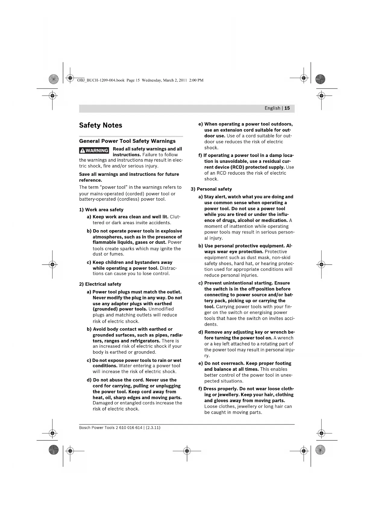
The machine is intended for drilling and routing tiles (ceramic, granite, marble, fine stoneware, natural stone) without the use of water.
Product Features
The numbering of the product features refers to the illustration of the machine on the graphics page.
1 Open-end spanner, size 17 mm
2 Handle strap
3 Union nut
4 Vacuum connection
5 Cutting depth adjustment knob
6 Clamping lever
7 Adjustable footplate
8 Light
9 On/Off switch
1.0 Thumbwheel for speed preselection
11 Retainer for hose holder
12 Handle (insulated gripping surface)
13 Collet chuck
14 Tool holder
15 Spindle lock button
16 Router bit
17 Vacuum hose
18 Holder for vacuum hose
19 Core bit
*Accessories shown or described are not part of the standard delivery scope of the product. A complete overview of accessories can be found in our accessories program.
Technical Data
| Tile Router GTR 30 CE | |
| Professional | |
| Article number | 3601 FOC 0.. |
| Rated power input | W 701 |
| No-load speed | min-1 15000 - 30000 |
| Speed preselection | |
| Constant electronic control | |
| Connection for dust extraction | |
| Weight according to EPTA-Procedure 01/2003 | kg 1.5 |
Protection class
同/II
The values given are valid for a nominal voltage [U] of 230V . For different voltages and models for specific countries, these values can vary.
Please observe the article number on the type plate of your machine. The trade names of the individual machines may vary.
Noise/Vibration Information
Measured sound values determined according to EN 60745.
Typically the A-weighted noise levels of the product are: Sound pressure level 82 dB(A); Sound power level 93 dB(A). Uncertainty K = 3 dB.
Wear hearing protection!
Vibration total values (triax vector sum) determined according to EN 60745: Vibration emission value a_h = 4.5 m/s^2 , Uncertainty K = 1.5 m/s^2 .
The vibration emission level given in this information sheet has been measured in accordance with a standardised test given in EN 60745 and may be used to compare one tool with another. It may be used for a preliminary assessment of exposure.
The declared vibration emission level represents the main applications of the tool. However if the tool is used for different applications, with different accessories or poorly maintained, the

English | 19
vibration emission may differ. This may significantly increase the exposure level over the total working period.
An estimation of the level of exposure to vibration should also take into account the times when the tool is switched off or when it is running but not actually doing the job. This may significantly reduce the exposure level over the total working period.
Identify additional safety measures to protect the operator from the effects of vibration such as: maintain the tool and the accessories, keep the hands warm, organisation of work patterns.
Declaration of Conformity C
We declare under our sole responsibility that the product described under "Technical Data" is in conformity with the following standards or standardization documents: EN 60745 according to the provisions of the directives 2004/108/EC, 2006/42/EC.
Technical file at:
Robert Bosch GmbH, PT/ESC,
D-70745 Leinfelden-Echterdingen
Dr. Egbert Schneider Dr. Eckerhard Strotgen Senior Vice President Head of Product Engineering Certification
Paa
Robert Bosch GmbH, Power Tools Division
D-70745 Leinfelden-Echterdingen
05.08.2010
Assembly
Before any work on the machine itself, pull the mains plug.
Adjusting the Handle Strap (see figure A)
Adjust the handle strap to the size of your hand to ensure safe operating with the power tool.
- Open the Velcro fastener of the handle strap 2.
Hold the machine with your hand and close the short strap as required.
Tension the long strap of the handle strap 2 and close the Velcro fastener.
Mounting the Adjustable Footplate (see figure B)
For routing applications, the footplate 7 must be mounted.
- Release the clamping lever 6.
Bring the marks on the power tool and the footplate 7 into alignment as shown in the figure. - Push the footplate 7 to the stop and close the clamping lever 6.
Replacing the Collet (see figure C)
Depending on the routing tool being used, the collet 13 may need to be replaced before inserting the router bit.
When the right collet for your router bit is already mounted, follow the work steps as described under "Adjusting the Depth-of-cut".
The collet 13 must have somewhat play when seated in the tightening nut. The tightening nut 3 must assemble easily. Should the tightening nut or collet be damaged, replace immediately.
- Push the spindle lock button 15 and keep it pressed. If required, rotate the motor spindle by hand until it locks.
- Unscrew the union nut 3 with open-end spanner 1.
- Release the spindle lock button.
- If required, clean all parts to be mounted prior to assembling, using a soft brush or by blowing out with compressed air.
- Insert the union nut into the tool holder 14.
- Hand-tighten the tightening nut.
Do not tighten the tightening nut of the collet without a router bit inserted. Otherwise the collet can be damaged.

20 | English
Inserting a Router Bit (see figure D)
For inserting and changing router bits, it is recommended to wear protective gloves. Router bits get hot during routing.
Original router bits from the extensive Bosch accessories program are available at your specialist shop.
Only use clean router bits that are in perfect condition.
- Push the spindle lock button 15 and keep it pressed. If required, rotate the motor spindle by hand until it locks.
- Loosen union nut 3 with open-end spanner 1 (size 17 mm) by turning toward 0.
- Insert router bit 16 into collet 13 to the mark on the router bit shank or until approx. 5mm of the router bit shank are still visible.
- Tighten union nut 3 with open-end spanner 1 (size 17 mm) by turning toward .
- Release the spindle lock button.
Do not tighten the tightening nut of the collet without a router bit inserted. Otherwise the collet can be damaged.
Dust/Chip Extraction
- Dust from ceramic tiles (quartz dust) or natural stone (mineral dust) can be harmful to one's health. Contact with or inhaling the dusts can trigger allergic reactions to the operator or bystanders and/or lead to respiratory infections.
Certain dusts, such as quartz dust, are considered carcinogenic. Materials containing asbestos may only be worked by specialists.
- As far as possible, use a dust extraction system suitable for the material.
- Provide for good ventilation of the working place.
- It is recommended to wear a P2 filter-class respirator.
Observe the relevant regulations in your country for the materials to be worked.
Connecting the Dust Extraction (see figure E)
Mount the vacuum hose 17 (accessory) onto the vacuum connection 4. Connect the vacuum hose 17 with a vacuum cleaner (accessory).
The machine can be plugged directly into the receptacle of a Bosch all-purpose vacuum cleaner with remote starting control. The vacuum cleaner starts automatically when the machine is switched on.
The vacuum cleaner must be suitable for the material being worked.
When vacuuming dry dust that is especially detrimental to health or carcinogenic, use a special vacuum cleaner.
Mounting the Holder with the Vacuum Hose to the Retainer for the Hose Holder (see figure F)
Fasten holder 18 and vacuum hose 17 by inserting them into the retainer for the hose holder 11.
Operation
Adjusting the Depth-of-cut (see figure G)
The adjustment of the depth-of-cut may only be carried out when the router is switched off.
For adjustment of the depth-of-cut, proceed as follows:
- Place the machine with the router bit mounted on the workpiece to be machined.
- Loosen cutting depth adjustment knob 5, so that footplate 7 can move freely.
- Adjust the desired routing depth by moving the footplate 7 up or down.
- The application tool should project at least 5 mm above the workpiece.
- Tighten cutting depth adjustment knob 5.
- Check the carried out depth-of-cut adjustment with a trial cut and correct it, if necessary.
Starting Operation
Observe correct mains voltage! The voltage of the power source must agree with the voltage specified on the nameplate of the machine. Power tools marked with 230 V can also be operated with 220 V.
Preselecting the Speed
The required speed can be preselected with the thumbwheel 10 (also while running).
15-20 Low speed
20-25 Medium speed
25-30 High speed
After longer periods of working at low speed, allow the machine to cool down by running it for approx. 3 minutes at maximum speed with no load.
Switching On and Off
Before inserting the mains plug, check if the On/Off switch 9 is switched off. Otherwise, the power tool can accidentally start and lead to injuries.
Adjust the depth-of-cut before switching on or off; see Section "Adjusting the Depth-of-cut".
To start the power tool, push the On/Off switch 9 forwards.
To lock the On/Off switch 9, press the On/Off switch 9 down at the front until it latches.
The light 8 is lit when the machine is switched on, and allows for illumination of the working range under unfavourable light conditions.
To switch off the power tool, release the On/Off switch 9 or, if it is locked, briefly push down the back of the On/Off switch 9 and then release it.
Constant Electronic Control
Constant electronic control holds the speed constant at no-load and under load, and ensures uniform working performance.
Soft Starting
The electronic soft starting feature limits the torque upon switching on and increases the working life of the motor.
Working Advice
Routing a Cut-out (see figures H-I)
Take care that the surface is free of any obstructions.
- Clamp the workpiece.
While working, hold the power tool firmly by the handle 12. - Guide the switched-on power tool toward the workpiece and plunge into the workpiece with moderate pressure at an angle of approx. 30 - 45^ with circular motion.
Slightly move the power tool up and down alongside the cutting line. - Carry out the routing process applying uniform feed.
- Switch the power tool off. Do not place the power tool down until the router bit has come to a standstill.
Routing with the Core Bits (see figures J-L)
The core bit 19 is used for routing/drilling a hole into a tile or e.g., a wall.
- Clamp the workpiece.
- While working, hold the power tool firmly by the handle 12.
Guide the switched-on power tool toward the workpiece and plunge into the workpiece with moderate pressure at an angle of approx. 30 - 45^
Slightly move the power tool with circular motion at an angle of approx. 15^
-Pay attention not to overheat the core bit 19. When using core bits with diameters smaller than 12mm provide for sufficient cooling, e.g., 10 seconds drilling, 5 seconds cooling. - Switch the machine off as soon as the workpiece has been drilled through. Do not remove or pull out the power tool until after the router bit has come to a complete stop.
- Work the cut-out blank out of the core bit 19 by applying a screwdriver via the lateral core-bit openings.

Maintenance and Service
Maintenance and Cleaning
Before any work on the machine itself, pull the mains plug.
For safe and proper working, always keep the machine and ventilation slots clean.
If the machine should fail despite the care taken in manufacturing and testing procedures, repair should be carried out by an after-sales service centre for Bosch power tools.
In all correspondence and spare parts order, please always include the 10-digit article number given on the type plate of the machine.
After-sales Service and Customer Assistance
Our after-sales service responds to your questions concerning maintenance and repair of your product as well as spare parts. Exploded views and information on spare parts can also be found under:
www.bosch-pt.com
Our customer service representatives can answer your questions concerning possible applications and adjustment of products and accessories.
Great Britain
Robert Bosch Ltd. (B.S.C.)
P.O.Box 98
Broadwater Park
North Orbital Road
Denham
Uxbridge
UB95HJ
Tel. Service: +44 (0844) 736 0109
Fax:+44(0844)7360146
E-Mail: boschservicecentre@bosch.com
Ireland
Origo Ltd.
Unit 23 Magna Drive
Magna Business Park
City West
Dublin 24
Tel. Service: +353 (01) 466 67 00
Fax:+353(01)4666888
Australia, New Zealand and Pacific Islands
Robert Bosch Australia Pty. Ltd.
Power Tools
Locked Bag 66
Clayton South VIC 3169
Customer Contact Center
Inside Australia:
Phone: +61 (01300) 307 044
Fax: +61 (01300) 307 045
Inside New Zealand:
Phone: +64 (0800) 543 353
Fax:+64(0800)428570
Outside AU and NZ:
Phone: +61 (03) 9541 5555
www.bosch.com.au
Republic of South Africa
Customer service
Hotline: +27 (011) 6519600
Gauteng - BSC Service Centre
35 Roper Street, New Centre
Johannesburg
Tel.: +27 (011) 493 93 75
Fax: +27 (011) 4930126
E-Mail: bsctools@icon.co.za
KZN - BSC Service Centre
Unit E, Almar Centre
143 Crompton Street
Pinetown
Tel.: +27 (031) 7 01 21 20
Fax: +27 (031) 7012446
E-Mail: bsc.dur@za.bosch.com
Western Cape - BSC Service Centre
Democracy Way, Prosperity Park
Milnerton
Tel.: +27 (021) 551 25 77
Fax: +27 (021) 5513223
E-Mail: bsc@zsd.co.za
Bosch Headquarters
Midrand, Gauteng
Tel.: +27 (011) 6519600
Fax: +27 (011) 6519880
E-Mail: rbsa-hq.pts@za.bosch.com
Disposal
The machine, accessories and packaging should be sorted for environmental-friendly recycling.
Do not dispose of power tools into household waste!
Only for EC countries:
According the European Guideline 2002/96/EC for Waste Electrical and Electronic Equipment and its implementation into national right, power tools that are no longer usable must be collected
separately and disposed of in an environmentally correct manner.
Subject to change without notice.
24 | Français
Senior Vice President
Head of Product
Engineering
Certification

Robert Bosch GmbH, Power Tools Division
D-70745 Leinfelden-Echterdingen
05.08.2010
Francais | 29
Montage
Robert Bosch (France) S.A.S.
Dr. Egbert Schneider Senior Vice President Engineering
Dr. Eckerhard Strötgen
Head of Product Certification
ppa. 1
Robert Bosch GmbH, Power Tools Division
D-70745 Leinfelden-Echterdingen 05.08.2010
38 | Espanol
Montaje
Senior Vice President Engineering
Dr. Eckerhard Strötgen
Head of Product
Certification

Robert Bosch GmbH, Power Tools Division
D-70745 Leinfelden-Echterdingen
05.08.2010
48 | Portugués
Montagem
- Antes de todoseworkos na ferramenta electricadeferapeuxarafichaderede da to-mada.
Dr. Egbert Schneider Senior Vice President Engineering
Dr. Eckerhard Strötgen
Head of Product
Certification
ppaaee i.v.
Robert Bosch GmbH, Power Tools Division
D-70745 Leinfelden-Echterdingen 05.08.2010
Montaggio
Senior Vice President Engineering
Head of Product
Certification


Robert Bosch GmbH, Power Tools Division
D-70745 Leinfelden-Echterdingen
05.08.2010
Montage
d) Brug违法犯罪.
e beleged to be a legal or official law enforcement activity, including the following:
- the conduct of any kind of illegal activity, including the conduct of any kind of illegal activity, including the conduct of any kind of illegal activity, including the conduct of any kind of illegal activity, including the conduct of any kind of illegal activity, including the conduct of any kind of illegal activity, including the conduct of any kind of illegal activity, including the conduct of any kind of illegal activity, including the conduct of any kind of illegal activity, including the conduct of any kind of illegal activity, including the conduct of any kind of illegal activity, being prohibited by law.
- the conduct of any kind of illegal activity, including the conduct of any kind of illegal activity, including the conduct of any kind of illegal activity, including the conduct of any kind of illegal activity, including the conduct of any kind of illegal activity, including the conduct of any kind of illegal activity, including the conduct of any kind of illegal activity, including the conduct of any kind of illegal activity, including the conduct of any kind of illegal activity, including the conduct of any kind of illegal activities, including the conduct of any kind of illegal activities, including the conduct of any kind of illegal activities, including the conduct of any kind of illegal activities, including the conduct of any kind of illegal activities, including the conduct of any kind of illegal activities, including the conduct of any kind of illegal activities, including the conduct of any kind of illegal activities, including the conduct of any kind of illegal activities, including the conduct of any kind of illegal activities, including the conduct of any kind of illegal activity, including the conduct of any kind of illegal activities, including the conduct of any kind of illegal activities, including the conduct of any kind of illegal activities, including the conduct of any kind of illegal activities, including the conduct of any kind of illegal activities, including the conduct of any kind of illegal activities, including the conduct of any kind of illegal activities, including the conduct of any kind of illegal activities, including the conduct of any kind of illegal activity, including the conduct of any kind of illegal activity, including the conduct of any kind of illegal activities, including the conduct of any kind of illegal activities, including the conduct of any kind of illegal activities, including the conduct of any kind of illegal activities, including the conduct of any kind of illegal activities, including the conduct of any kind of illegal activities, including the conduct of any kind of illegal activities, including the conduct of any kind of illegal activity, including the conduct of any kind of illegal activities, including the conduct of any kind of illegal activity, including the conduct of any kind of illegal activities, including the conduct of any kind of illegal activities, including the conduct of any kind of illegal activities, including the conduct of any kind of illegal activities, including the conduct of any kind of illegal activities, including the conduct of any kind of illegal activities, including the conduct of any kind of illegal activities, including the conduct of any kind of illegal activity, including the conduct of any kind of illegal activity, including the conduct of any kind of illegal activity, including the conduct of any kind of illegal activities, including the conduct of any kind of illegal activities, including the conduct of any kind of illegal activities, including the conduct of any kind of illegal activities, including the conduct of any kind of illegal activities, including the conduct of any kind of illegal activities, including the conduct of any kind of illegal activity, including the conduct of any kind of illegal activities, including the conduct of any kind of illegal activities, including the conduct of any kind of illegal activity, including the conduct of any kind of illegal activities, including the conduct of any kind of illegal activities, including the conduct of any kind of illegal activities, including the conduct of any kind of illegal activities, including the conduct of any kind of illegal activities, including the conduct of any kind of illegal activities, including the conduct of any kind of illegal activity, including the conduct of any kind of illegal activities, including the conduct of any kind of illegal activity, including the conduct of any kind of illegal activity, including the conduct of any kind of illegal activities, including the conduct of any kind of illegal activity, including the conduct of any kind of illegal activities, including the conduct
e) Hvis el-vaerktojet benyttes i det fri, ma der kun benyttes en forlaengerledning, der er egnet til udendors brug. Brug af forlaengerledning til udendors brug ned-sætter risikoen for elektrisk stød.
f) Hvis det ikke kan undgas at bruge el-vektjet i fugtige omgivelser, skal der bruges et HFI-relae. Brug af et HFI-relae reducerer risikoen for at fa elektrisk stød.
Dr. Egbert Schneider
Dr. Eckerhard Strötgen
Senior Vice President
Head of Product
Engineering
Certification
Paa.
Robert Bosch GmbH, Power Tools Division
D-70745 Leinfelden-Echterdingen
05.08.2010
Montering
Bosch Service Center
Telegrafvej 3
2750 Ballerup
Tel. Service Center: +45 (4489) 8855
Fax:+45(4489)8755
E-Mail: vaerktoej@dk.bosch.com
Bortskaffelse
Dr. Egbert Schneider Senior Vice President Engineering
Dr. Eckerhard Strötgen
Head of Product Certification
Paa. Mua i.v. Nauogcu
Robert Bosch GmbH, Power Tools Division D-70745 Leinfelden-Echterdingen 05.08.2010
Montage
Dra stickproppen ur nätuttaget innan arbeiten utfors pa elverktyget.
Bosch Service Center
Telegrafvej 3
2750 Ballerup
Danmark
Tel.: +46 (020) 41 44 55
Fax: +46 (011) 187691


Svenska 85
Avfallshantering
Dr. Egbert Schneider Senior Vice President Engineering
Dr. Eckerhard Strotgen
Head of Product Certification


Robert Bosch GmbH, Power Tools Division D-70745 Leinfelden-Echterdingen 05.08.2010
Montering
Dr. Egbert Schneider Dr. Eckerhard Strotgen Senior Vice President Head of Product Engineering Certification
Paa /aa /i. Noo
Robert Bosch GmbH, Power Tools Division D-70745 Leinfelden-Echterdingen 05.08.2010
Asennus
AiaβaTe oλεις unodεiεic ασραλeia
Kai Tc obnyec. Ameieic kata tv thponTov unobeiEev aoepaiaac kai twv onyiw npopei va npokaleounv nkeptponanxi, npkayia n/ka obaopouc tpaumatouoc.
DuAeTe oAcTic npoeBOnoIntKeC unObeEieK KAI osnyie,vi kahe eMaovrki xphn.
O opiaoc Hktpko epyaleo nou xpnoiopoieitai otipoeisotniikc unoileic avapeptai o naktpka epyaleia nou tropoosotovtai ano to nektpko biKtu o nektpko kaawio kai e naktpka epyaleia nou tropoosotovtai ano mntapia (xwpi c nektpko kaawio).
1)AoPaeia oTo xwpo epyaioa
a) Diatnpette Tov topea nou epyaceoKe kaapokai kala wioevo. Aataia n okeivc nepioxec epyolaac unopei va oynoov oe atuxnata.
b) Mny epya2e0e me to nAekpiko epya Aio oe nepiaalov onou unapxke kivuvo ceknnc, oto onolo npoxuv e- pAekta upa, aepia nokovec. Ta nAekptka epyaia 6nuioupoyov onivnpiuo o onoloc mnpoei va avapaeei tn okovn Tic avaohmuaoic.
c) Otav xnpaonoielte to nkektipko epya.
leio kpatate paikpi an' auto ta naibia ku
dAAA tuxov napeupkokoeva atoa. 2e
nepintwn ananaanctn npooxnc aac
muopei va xaote tv eleyxo tou mnxavn
muatoc.
Senior Vice President
Head of Product
Engineering
Certification


Robert Bosch GmbH, Power Tools Division
D-70745 Leinfelden-Echterdingen
05.08.2010
EAnviKa 107
Sigma
ByaTeTo qic ano TIV npia npiv ano onouhnotepyaogla oTo nkeptko epyaaleo.
Pouon maVta ouykpatnonc (Ble n e ukova A)
Aaayn Tou Tookakloou (Bene Ekova C)
Piv tonothe nT pceca nou 0a xpnoonoioe npene va aaaaEeTo T ookaki 13.
Otau, omuoc, elva hsn ouvapmooynevo to Taokaknou taipiaceotnppecaac,tote aokouthetaTn diadkaala nou npepypaetai oTo kepalaio Ppuonbaouc pcpzaplaatoc>.
To Tookaki 13 npenei va kaioei pe liyo 己 naiviDto naiaudi e emikalmu. To naiaudi ie enikalmu3 npenei va npoei va ouvapoloynthetae uekolia. Na avtkaotate apoew to naiaudi ie enikalmu n to Tookaki otav xalaouv.
Na xpnaiponoiieTe mOvo apiotec kai kaapec ppce.
- Pntnote kai kpatnote natnnevo to nAnktpo avdaawonc eOva 15. Av xpeiaotei, yupioTe Tov dOva pe To xepi pexpi va vdaaloei.
AutaTo naIaIabiIe emkakluma 3e To yepauviK kIe1b1 (avoivpa Klebiou 17 mm) pe popa nepiotpophc
OeIATE Tn pEca 16 eaa oTo Tookaki 13 exoTo anuabi enavw oTo aExoc Tnc n ew va paivovtai akoun nepinou 5 mm tou oExoxou Tou evayaleou. - ΣφιEτe kaλa to naεμδι με επικαλμμα 3 με to yερμανικό κλειδι 1 (dαογμα κλειδιου 17 mm) yuριζοντάστο με φρό περισροφής.
-Apnte eaeuthetao to nAHTPO aVbAwoonc aOva.

108|Eaaynuka
Mn opiEe note to tookaki me to naqmuabi me emkakmu xwplc va exete ouvapmooyoeepyaleio ppeapiaopoc. Aiaopopetika unopei va unootel to TOKAKI.
Avappopnonokovnc/pokavibwv
O1 oKovec ano kepaikia nlaakkia (okovec xalaizia) kai quoka ntpwmuata (okovec ano opukta uikia) mnopei va elva avuyieivc. H enapn h n eianvov taw okovw autuvmnopei va npokaleoi oTO xpohtn oE tuxov napepiokoeva atoja aAlepkyiek avtbpaeic n/ka aOveiec twy ayanveotkiow odwy.
Opiouevc okev,c. x.ano xaala,
eewpuovtai wc kapkivoyovl.H katepyaola
aiaivtoxwuy uikov enipenetai mvo oe
katalnaeknaibeupevo npoowniko.
- Na xŋnəpmonoiite kara to duvato yia to ekáotore uikó tny katαλληan avappoŋn.
- Na φροντιζετη γι τον καλό αεριαμό του χωρου εργασιας.
-2aouBouLeoupe va opate paokec avanveoiknc npoataiae peiAtpo katnyoplaC P2.
Na Tnpelte Tc biataEic nou loxov ou nXwpaa yia Ta biapopa uno katepyaola uikia.
Uv6eTnC avappoPAnc oKovnc (BaeEikova E)
Tonoetto oawhyavappopnonc 17 (npoaipeTKo eApntma) oTo aTpiyma avappopnonc 4. SuVbeTe to oawhya avappopnonc 17 me evav anoppopntnpa kovnc (npoaipeTKo eApntma).
To nEeKpIcO epVaIeI oIopel va tonoetIeI kateuoeiaov npia evoc anoppopnTpa Okovnc yeviNc XpHNC Tc Bosch, EonlIoEvou ue autOpaTn diataEn ekivnanc. O anoppopnTnpac OKovnc Eekiva autOpata mIoIc Teel e aeIoupyla to nEeKpIcO epVaIeI.
O anoppoqntnpac oKovnc npenei va eivai kataaAnaoC yia to ekaoTote uno katepyaala uiko.
Tia tv avapppon 1ialtepa avuyieivnc, kapkioyovou nEnpnc oKovnc npenei va xpooioite eikouc anoppopnnpec oKovnc.
EuuppoIaoynon rou oukykparthpa otnv unooxni yia oAanoppoqnoC (Baeicova F)
Tepeote to oukypatnpa 18 kal to oawnva anoppoepnnc 17 wovtac touc mea otyn unooxyoukypatnpa owna 11.
Aetroupyia
Pouon baooc qpezapiaopac (Bene eikova G)
HpuoMtuonoubaOoucpezapiaopac npenevaieayetai movot to nAekptipkoepyaleloexTeelktoe Aetoupyla.
Tpoemloyn aptouo stpov
MeTov TPOXIOKOpuOIOIgN PPOeINAOyAn apIOoou OTOPOw 10 mOpoeite va enIAEeTe Tov eINoUmTo aIIOuOStoOv,akoun kai katn diApkeia nC Aetoupyiac.
Dr. Egbert Schneider
Dr. Eckerhard Strötgen
Senior Vice President
Head of Product
Engineering
Certification
Paa Maae i.v. Nogc
Robert Bosch GmbH, Power Tools Division D-70745 Leinfelden-Echterdingen 05.08.2010
Montaj
Penset 13征求意见 - Pensions and benefits - Pensions and benefits - Pensions and benefits - Pensions and benefits - Pensions and benefits - Pensions and benefits - Pensions and benefits - Pensions and benefits - Pensions and benefits - Pensions and benefits - Pensions and benefits - Pensions and benefits - Pensions and benefits - Pensions and benefits - Pensions and benefits - Pensions and benefits - Pensions and benefits - P pensions - P pensions - P pension - P social security - P medical benefits - P pension - P social security - P medical benefits - P pension - P social security - P medical benefits - P pension - P social security - P medical benefits - P pension - P social security - P medical benefits - P pension - P social security - P medical benefits - P pension - P social security - P medical benefits - P pension - P social security - P medical benefits P. Pension P. Social Security P. Medical Benefits P. Pension P. Social Security P. Medical Benefits
Devir saysi on seclimi
Bosch San. ve Tic. A.S.
Ahi Evran Cad. No:1 Kat:22
Polaris Plaza
80670 Maslak/Istanbul
Müsteri Danismani: +90 (0212) 335 06 66
Müsteri Servis Hatti: +90 (0212) 335 07 52
Tasfiye
Senior Vice President
Head of Product
Engineering
Certification
ppa. 1
Robert Bosch GmbH, Power Tools Division D-70745 Leinfelden-Echterdingen 05.08.2010
124 | Polski
Montaž
System Constant Electronic
Robert Bosch Sp. z o.o.
Dr. Egbert Schneider Senior Vice President Engineering
Dr. Eckerhard Strötgen
Head of Product
Certification

i.v. MoDgcu
Robert Bosch GmbH, Power Tools Division
D-70745 Leinfelden-Echterdingen
05.08.2010
Montáz
Bosch Service Center PT
K Vapence 1621/16
692 01 Mikulov
Dr. Egbert Schneider Senior Vice President Engineering
Dr. Eckerhard Strötgen
Head of Product Certification
ppa. 1000 i.v. nuOycu
Robert Bosch GmbH, Power Tools Division
D-70745 Leinfelden-Echterdingen 05.08.2010
Slovensky | 141
Montáž
Dr. Egbert Schneider Senior Vice President Engineering
Dr. Eckerhard Strötgen
Head of Product Certification


Robert Bosch GmbH, Power Tools Division D-70745 Leinfelden-Echterdingen 05.08.2010
Összeszerelés
- PpIMHeHrTe IpoTHBOBtBeBOe peCtnHpTOp.
Onncahne npoaykTa n ycayr

TpouHTHe Bce yka3aHn HnHcTpyK- nno TeXnKe 6eOtnaHocTH.
PnHIOIopaxeHH3AektpueckmTOKOM, IOXapaN TaeBIX TpaBM.
YnyueHnB OTOHOeHNyka3AHn HNCTpyKuI NTOxHKe 6eOJIaChOcTHMOrT CTAtb
TkoAmyCTa,OTKpoTe packAaHyo cTpaHnuy C HIOCTpauNMA 3AEKTPoHNCTpyMeHTa N OCTAB AYIe ee OTKpbITOn,POKa Bb IaYaeTe pyKOBOdCTBO IO 3KcTIayatauIN.
PpHMeHeHnTo Ha3HaueHnIO
3AekTPOHnCTpyMeHT PpeHa3HaueH DA CBepAENH NΦpe3epoBAHH NANTKN (KepaMKN, rpaHNTa, MpaMopa, NNTKN Tpec, PnpOaHORO CTponTeABHO KAMH) 6e3 NcnoB3OBAHN BOAbI.
H3o6paXeHHbIe COCTaBHeIy aactn
HymepaunI ppeactaBAeHHbIX KOMTOHEHTOB BbIIOAHeHa IIO 3o6paKeHHo Ha CTpaHnue C HIIIOCTpaUAMN.
1BnOuHbIKaIOcpa3mepoM 17 MM
2 PeMeHb
3HaKnHaRaKa
4Iatpy6ok oTcoca
5Iobopotharpyka peryanpoBaHHraay6nHbIΦpe3epoBaHH
63aKIMHObIaI
7 Perpynpyem an oTOpHa nTa
8AamTouka
9 BbikAnOHTeA
10 YctaHOBOUHoe KOeCnKo Ucna O6opotOB
11IHe3DoAaKpeHaeHHaHaHa
12 PyKoTka (c H3OAnpoBaHHoH IOBepxHOCTbHO
133axmHaaHa
14 NaTPOH
15 KhoTka qKcaun HnHaeA
16Φpe3a*
17WHaHOrtCaBbAHH
18 KpePAnHeHneAaHaHa rOtcabBaHnra
19 KopoHuaToe CBePao*
*H3o6paXeHHbI HN OTHCAHHbI IprnHaAeXeHXOCTH He BXoART B CTAnAPrTHbIO6bEM NocTABK. TOnhBIOAccOPTMHe IprnHaAeXeHXOCTe Bbl HaDeTe B hAaeI pOrpPamE MPrnHaAeXeHXOCTe.
158 | Pycsckn
TexHnueckne daHHbIe
AaHhIe IIO Wymu N Bn6paunu
YpOBeHb Wyma ONpeDeAen B COOTBeTCTBnC eEBPOeNcKoHOPMoEN60745.
A-B3BWeHHb ypOBeH bWymaOT 3AEKTPoHnCTpyMeHa COCTABARET O6bIuHO: ypOBeH 3ByKOBO rAbAeHNr82 AB(A); ypOBeH 3ByKOBo MoUHcTHN 93 AB(A). HeoctOBepHoCTb K=3 AB.
IpHMeHnTe CpeAcTbA 3aunTbOpraHOB cyxHa! O6uHe 3NaueHnKoLe6aHn (BeKToPnaCymMa Tpex HATPaBaeHn) OTpeDeAeHb corlaacho EN 60745:
Bn6paun a=4,5M/c²,TOrpeuHoctb K=1,5M²/c
Yka3aHHb B HactoIuXn INHctpyKunx npOBBeH b6paun n3mepeH IIO MeTOAnke n3mepeHn, IPOncanHO B cTaNapTe EN 60745, n MoKeT
6bTbNCIOaB3OaH DA cpaBHeHH
3AEKTPoHNCTpyMeHTOB. OH pIPOeH TaKke A
PiEBApHTeALHO OeHKn Bn6paunHOH
Harpy3k.
YpOBeHb Bn6pauny Kya3aH DA OCHOBhix BnIOB paOToBc 3AeKTPoHHCTpyMeHTOM. ODAHO eAH NAEKTPoHHCTpyMeHT 6yETNCTOAB3OBAH ABAI IOAHEHNA DpyHX paOBT C PpIMHeHem paOChx HnCTpyMeHOB, He IpeDyCMOTpeHHbIX N3TOTOBNTeAM, HN TxHNueckoe 06CAYKBaHne He 6yET OTBeuATb PpeADHCAHmN, TO ypOBeH bBnPaun MOKet 6bITb NHBM. 3TO MOKeT 3HaUHTeBHO IOBbICNTb Bn6paUNOHHy HArpy3Ky B TeueHHe BcE TPOAOXHTeBHOCTn paOToBt. AAn ToHOn OueHKn Bn6paUNOHHO Harpy3Kn B TeueHne ONPeDeAEHHORo BpemeHHoro INTEPBAa HxJHo yUHTbBaTb TaKxe N BPeM, KOrDa IHCTpyMeHT BblAIOueH HN, XOTN BkAUoyeh, HO He HaxODHTCB PaOte. 3TO MoKET 3HaUHTeBHO COKpaTHb HArpy3Ky OT Bn6paUNB paCaeTe Ha TIOHoe paoOee Bpemr. IIpeDyCMOTpnte DOIOAHTeBHLbe MepbI 6e3-OTaCHOCTn AAN 3aUnTbI OIEpaTopa OT Bo3dEICTBn Bn6paUN, HApPImep: TexHNueckoe 06CAYKBaHne 3AeKTPoHHCTpyMeHTa n PaOounx IHCTpyMeHOB, MepbI IIOPOAdpKaHNO pyK B TEaE, OprAHIN3aUNTEXHOAROpueCCOB.
3aRaBHeHne o COOTBeTCTBn

CIOAHOHOTBETCTBEHHOCTBIO Mbl3aRBAEM,TOOINCAHHBIBpa3dEe《TexHnueckne DaHHbIe》IPOADyKT COOTBETCTByET HNKeCEyIOUHMCTaHApTAM HAN HOPMaTHBHBIM DOKyMeHTAm:EN60745coHaacHOIIOXeHNAMDInpeKTH2004/108/EC,2006/42/EC.
TexHueckA DOKyMeHTaun: Robert Bosch GmbH, PT/ESC, D-70745 Leinfelden-Echterdingen
Dr. Egbert Schneider Senior Vice President Engineering
Dr. Eckerhard Strotgen
Head of Product Certification
Paa.
Robert Bosch GmbH, Power Tools Division D-70745 Leinfelden-Echterdingen 05.08.2010
C6opka
IpeaAIO6bIMM MaHHTyAunmMC 3AeKTPoHHCTpyMeHTOM BbITACKnBaHTe 1TeTceAb H3 po3eTK.
PerynpoBaHne pemHa (cm.pnc.A)
OtperyHpytepeMeHBcoOTBcTBN c pa3MepoB Baaew pykn, yTO6bl o6eTeuHTb 6e0tacHoctb pa60TbI C 3AEKTPOHHCTpymENTOM.
-PacTeRHTeAUYkypeMn2.
-Ппдержenteэктponнсремпг рковипри Heo6xOAMOCTN3akpoTte KOPOTKNI 83bIyOK.
HaTAHHTeAHHHbIa3bIyOKpeMHra2N 3acteHTHeAANTyKy.
MOHTAX peryAnpyEmoOn oToPHOI PANTBI (cm.pnc.B)
AaPpeepoBaHHn Heo6xOAMMO MOHTnpoBaTb OTOpHyo TANTy 7.
-OTKpoIte3axmHnOpbuAr6.
-COBMECTHTeOTMeTKHa 3AekTPOHNHCTpyMeHTe HOTOPHOIANTe7,KAK 3TO TOKa3aHO HA pncyHKe.
BCTaBbTe onOpHyI MHTy 7 Do ynpa n 3akpoTe 3aKHMHO pbiar 6.
3aMeHa 3axHMHO uAHn (cm.pnc.C)
B 3aBnCnMoCTn OT pIIMeHReMOn Φpe3bl Heo6xOaHMo IpeA yCTaHOBkoI Φpe3bl 3aMeHHTb 3aKmMHyU caHry 13.
TocmeMOHTaKaIIOxOaIeIAAfpe3bl 3axHMHOUaHnBbIIOAHNTeMaHITyAUNM, OTNCAHHBeBpa3dEAEYCTaHOBArEy6HbI fpe3epoBaHHa.
3aKHMHaaHa 13doAkhCa CnTeB HaKnHHOI raKe C He6oBWM AIOFtOM. HaKNHARraKa3 doAkhHaAerKO MOHTnpOBaTcR.Ipn IOBpeXeHNHaKnHOr RaIKN NAn 3aKHMHOI ZaHrHeMeDAnEHHO 3aMeHHTe ee.
-HaXMMTe Ha KHOITky 6oKnPOBKN WHTNHeAe15 n yApEKNBaIte ee Haxato. PnHcOxOAMOCn TIOBepHnTe pyKo WHTNHeAeABnTaTeA, YTO6bl3aФHKCpOBAb erO.
-OTKpyTHeHaKNAnHyTo RaNky 3 BnAouHbIM KAIIOYOM1.
-OTnycnte KHOITKy Hkcaunu HnHaeA.
-Пин Heo6xOAnMoCTH OunCTHteпepeA MOHTaXOM BCE MOHTnpyeMbIe DeTaAN C TMOUbHO MfKoI ΜeTOuKn HAN PPOaYIte HX CXaTbIM BO3dYxOM.
BcTaBbTe HaKHaHyo TaKy B NaTPOH 14.
- Cserka 3aTnHte HaKnAnHyr raKy.
HnB Koem Cnyae He 3aTnBaIte HauHyraKy 3axmHOn ZaHr6e3 fpe3bl. Hnue 3axmHaHa ZaHa MoKeT 6bItb TOBpeXkDeHa.
YcTaHOBkaΦpe3bl (cm.pnc.D)
Pn yctahOBke HAn 3aMeHe fpe3bl Mbl peKoMeHApEOMeBaTb 3aunTHbIe pyKaBnbl. Pn o6pa6otKe fpe3bl HaPeBaHOtCn.
OpnHaBHe 06HpHOn
IporpaMMb IpnHaAeXHOCTe HmPb Bosch
MOxHO IpiNo6peCtB CteuaaHnpoBaHHom
Mara3HHe.
PpIMeHnTe ToAbo 6e3yKOpn3HeHHbIe N nCTbe ppe3bl.
-HaKMTHe Ha KHOITky 6oKnPOBKN IINHDAEIA 15 n ydepxkBaIte ee HaxatoN. PpHne6xOAnMOCTn IOBePHTe pyKo WtINHDAEAB DnraTeA, YTO6bl 3aФNKcnpOBaTb erO.
OTTNTHe HauHHyu rAky 3 BnOuyhIM KHOyOM 1 (pa3Mep KHOya 17 MM),IOBepHyB ee BHaIpaBAeHHN 0.
BCTaBbTe 16 OToMTKN Ha XBOCTOBnke B3aKmMHyUaHry 13 NAn UTO6bl XBOCTOBnK pa6Ouyero INCHpyMeHTa BBIARABBaII Pn6A. Ha 5 MM.
-3aTAHHTe HAKHHyIO raiKy 3 BnOuHbIM KHOUOM1 (pa3Mep KHOua 17 MM), NOBepHyB ee B HAtpaBHeHH
-OTnyCTnTe KHOIIKyΦHKcaUNIINHINHaeIA.
HnB Koem Cnyae He 3aTnBaTe HauNHyu rayky 3axmHOn caHr 6e3 fpe3bl. Hnue 3axmHaHa cHaRa MoXe 6bItb IOBpeXeHa.
160 | Pycsckn
OTcOC TbIH N CTpyKKn
TbIbOT KepaMuecko IANTKN (KBapueBaB TaIb) HIN PnPOHOCTPOnTeABHOKAMH (MnHepaAIBHAR TbIb) MOKeT 6bITb BpeHOH DAA 3AOPOBBa. KOHTC T bIbBO HAN BbIXAHNE TbAI MOKeT Bb3BaTb y OTEpatoa HN AIOEHN, HAXOARXCS NOBAM30CTN, aAeprHueCKne peAKUNH N/AN CTaTB pNpuHNO 3a6OBeAHN dXbATEhBHX PyTeH. HeKoTOpBle BNbI TbIIH, KA HAp.. KBapueBaTbIb, CUHTaIOTc OTuaCTN KaHcporeEHbIMn. IopyaHTe o6pa6OTky COaepKaUeO ac6ecr MaTePhaTaToLbKO CteuHaHCTAm.
-TO BO3MOXHOCTN HCIOa3yTe PnroAHBn AAR MaTePnaA TaIEoTcOC.
-Xopowo npoBETpBaIte pa6ooye MeTo.
- PeKOMeHdyTeTcNIOAb3OBAb7cpeCnHpaTOpHoMACKoCΦnABTpOMKaaccaP2.
Co6IaTe DeHCTByUeN BaWei cTpaHe IpeAHCnHn DAo 6pa6aTBbBAemblx MaTePnaAOB.
TpncoeAHHHnEeOToCoca (cM. pnc.E)
HaedeHbTe 17 (PnHaAeXHoCTb) Ha TpTy6oK OTCoc4. CoaHHte 17 CbIaeCOCOM (PnHaAeXHOCTn).
3eKTPoHCTpyMeHT MoKet 6bItb IOAKnOueH
TIPMO K WTeIeCABHOI PO3ETKe YHNBepCaABHO
TbIEcOCa HpMBo Bosch c yCTPOHCTBOM
AnCTaHUNOHHO TysCA. TbIEcOC
aBTOMaTHUeCKN 3aITyCKaETcPn BkIOueHH
3eKTPoHCTpyMeHTa.
TbIeocdoXKeH6bTbpHroDeHAAOBpa6aTbBaemoroMATEpHaA.
PnmeHnTe CteuHaBbI PbIeCoc DAOTcAcblBaHHO Oc06 BpeAHbIX DAn 3ApOBoB BnOBO TbAN -BO36yDHTeEpa Hn CyXoPiBn.
Mohtax KpeHennn Co 7aHarom OTCacbBaHH B rHe3eA4 KpeHennn 7aHaHa (cM. pnc. F)
3aKpeNTe KpeTHe 18 nIaHaT OTCacbBaHn 17, BCTaBnB IN B rHe3o DA KpeTHeHn IaHaHra 11.
Pa6ota c nHcTpymeHTOM
YcTaHOBka rAy6HHbI fpe3epoBaHn (cm.pnc.G)
YctahOBkyIay6HbIΦpe3epoBaHHpa3pewaetc BblIOAHTb ToBko IIpN BbIKAOeHHOM 3AEKTPoHHCTpyMeHe.
HactpoKyIy6bHbIΦpe3epoBaHnB BblIOAHRte CLEdyOuM 06pa3om:
- YcTaHOBInTe 3AekTPOHNHCTPymENT C 3aKpeIeHHoH Φpe30 Ha IIOAnExaUyO 6pa60Te DeTaIb.
OTnycHTte NOBOPOTHyO pyky peryInpOBaHnRAy6bHbI ppe3epoBaHn5, 106bl OTOpHa7 MoA CBO6oHo nepemeeatcb.
IpnAIBRnHnOToBnraOnOpHyIOHTy7, HAcTpoTe HyKHyrIy6hMyΦpe3epoBaHn.
-Pa60H INCTpymENT DOAXEN BbICTyIaTb 3a 3aTOBky MHN. Ha 5 MM.
-3akpyTHe TIOBOPOTHyO pyky peryAnpoBaHn rABybHb fpe3epoBaHn 5.
-ПpoBepbTe HAcTpoEHHyIry6HHy Φpe3ePoBaHHHa IpaKTHKe I IOkOppeKTHpyIte ee IIpn Heo6xOAnMocTN.
BkaoueHne 3aektpoHHctpymeHa
YuHTbIaBte HAnpXeHne cTe! HAnpXeHne NcTOUHnKa TOka DOAXHO COOTBeTcBOBaTb DaHHbIM Ha 3aBOAcKoI Ta6AuKpe 3AekTpOHnCTpyMeHTa. 3AekTpOHnCTpyMeHTb Ha 230 B MOryt pa6OtaTb TaKke I pN HAnpXeHnn 220 B.
Hactpoika qncaa o6opoTOB
C NOMOUByU yCTAHOBOHORo KOAEChka 10 Bbl MoXeTe yCTAHOBHT Heo6xOAMoe YHCAO O6OpOTB TaKHe N BO BPempa60tbl.
15-20 Hn3Koe YnCnO 6OpOTOB
20-25 cpeAHee uHcAo 06opoTOB
25-30 BbICOKoe uHcAo 06OpOTOB
Tocae npoOAnTeAHO paOToI C Hn3Km
HcAOM o6oPoTOB 3eKTPOnHCTpyMeHT CAdyET
BkAIOHTb Pn6An3TeAHO Ha 3 MnHyTb Ha
MaKcMaAbHOoe HCAo o6oPoTO B HA XoIoCTOM
XOy DA OXIAJAEHH.
Pycckn | 161
IpeaAIO6bIMMaHHTuAunMnC 3AEKTPoHHCTpyMeHToM BbITACKHBaTe WTeTceAb H3 pO3eTK.
AIO6epeHn KaecTBeHHo H 6e3oTacHOH pa60tbl CaeAyET IOCTOHHo COApKAtb 3AEKTPOHHCTpymEt N BEHTHAUHOHbI UeAN B YHCOTe.
Ecan 3AektpoHnCTpyMeHT, HecMOTp HA TtataBbHbIe MeTOaBI N3rOToBAeHHN INCITbTAHHN, BblETn3 CTPoR, TO pEMONT CLEyET PPOIN3BOAnTcNAAMn ABTOPIN3OBaHHO CEPBCHOH MaCTepCKOn DAAN AAEktpoHnCTpyMeHToBΦHpMbI Bosch.
TIOXaIyIcTa, BO BCEx 3aIpOacn 3aKa3ax 3aIyIaCTe 06raTeAbeHo yka3bIbaTe 10- 3HaHbI TOBapHbI HOpE p IO 3aBOdCKoI Ta6AnKe 3AEKtpOnHCTpyMeHTa.
CepBnchoe 6cbyKbHaHne KOHCyIbTaunr NOKyIaTeJe
CepBnchbI OTeA OTBeTn Ha BCE Baun BoPocBcI IO pemOnHy I ObcayKbAHnIO Bauero IpoDyKa, a TAKKe IIO 3aIuaCTHM. MoNTaXHbIe ueptexN INHOpMaunIO 3aIuaCTM Bbi HauDeTe TaKke IIO aApecy:
www.bosch-pt.com
KOMeKTHOBKOHcybTaHTOB Bosch OxOTHO TomoKet Bam B Bonpocax NOKyIKN,IPnIMHeHNu HAcTPOKn PpOdyKTOB INPnHaAeXHoCTeN.
ApernoHa: Pocn, Beapycb, Ka3axTah
RapaHTnHoe 06cAYKbAHHe n peMOHT 3AeKtpoHnCTpyMeHTa, C cO6AIODeHHem Tpe6OBaHn HOpM N3ROTOBNTeA IPOUN3BOADTCa Ha TeppnTOpNn BCEX CTpaH TOAko BΦHpMeHHbIX nn ABTOpN3OBAHHbIX cepBnCHbIX ueHTpax «Po6epT BoW».
IPEyIPTEKAEHNE!NcnoB3oBaHne KOHTpaΦaKTHOI pOdyKuHN ONaCHO B 3KcIpyatauNN,MOKET pINBeCTN KUepe6By DAA BaWero3aOpOBb. N3rOToBAeHne n pacnpoctpaHHeNKeKoHTpaKaTHOH pOdyKuHN PecaeDeYETCnTO3aKHy B aAMHHCTpAHBOM yTROABHOM TPORAKE.
Pocchra
OOO «Po6epr Bow»
CepBnchbIuHTpNo 06caykBaHHIO
3AekTponHCTpyMeHa
ya.Akaemika KopoIeBa, ctp. 13/5
129515,MockBa
Poccn
TeA.:+7(800)100 800 7
E-Mail: pt-service@ru.bosch.com
TOnHyIO HhOpMaunO pacnAoKeHHN
cepBnchbIX ueHtpOB Bbl MoKTe TIOyUHTb Ha
He BbIbpaBbIaTe 3AekTpOuHcTpyMeHTbI B 6bIbOo Mycop!
ToAko AAR CTpaH-4eHOB EC:

Corlacho Ebpoeckon AnpeKtnBe 2002/96/EC o cTapbix Aektpnuecknx HAnEeKtpoHHbIX HnCTpy
MeHTax I npnbopax n aDeKBaTHOMy IpeDnHCaHNO HAHOHaBHOI pBa,OT
CAYKBWNE CBOB CPOK 3AeKTPONHCTpyMeHTbl DOXHBIO TDAEALHO CObpaTbcn N CdaBaTbcn Ha 3KOANOHNueckn YNCTyO yTNNA3aunO.
Bo3MOxHbI n3MeHeHHa.
Bka3iBkn 3 texhikn 6e3neKn
3araabhi 3actepexeHHA AAn eAEKtpponaIb
A NONEPEIXEHHA
IpoountaTe BcI 3actepexheniBkazibKn.
HeOpTPhMaHHa3aTepeXeHbI Bka3iBOK MoXe Ipn3BecTHo ypaXeHHa eEKeTpHuHM CtpyMOM, ToxekjTa/a6o cepno3nX TpaBM.
O6pe 36epiraTe Ha Ma6yTHe ci TonnepeA- XeHHI BkazBkn.
PiI IOHHTTAM 《eEeKtpoPnPAaB》B uXx 3acTepeKehHHMaCTbCaHa yBa3i eEeKtpoPnAA,IOItpaioe BiD Mepeki (3 eEeKtpokaBelem) a6o BiAcMyAITOPHO batapei (be3 eEeKtpokaBeIo).
1) Be3πεka ha po6ooumy micui
a) TpmaTe CBOe pO6ou Micue B uHcToti i 3a6e3neute DO6pe OCBITaENHa pO6oMy Micui Moxyt b Pn3Becn Do HeuacnX BnAkB.
6) He npaHoe 3 eAektpoPnHaam y cepeoBnui, de icHy eHe6eTneKa Bn6byx BHacIaOk PnCpTyHOCTi RopOuNx PiHN, ra3IB a60 NMy. EaeKtpoPnHaAM MoKyTB IPOADKyBaTH iCKPN, BiJrKnx MoKe 3aMmTaC nA a60 napn.
B)Пдчacпрацi 3 ealeKtpoPnHaaOM He pIaTnyckaHTe Do po6OyOrO MicuA Dte Ta IHxN AIOeB MoKTe BpTaNTn KOHTpoBa HAd PnHaADom, RaIo BaWa yBara 6yde BiABepHyta.
2)EeKtpnHa 6e3neKa
a) WTeTceAeKToPpHAAy TOBHHeiXoAnTH Do po3ETKn. He Do3BOAerbCmHrN 0ocB WTeTceAi. AaPo6Otn 3eAEKToPpHAAdAMn, 0o MaHOt b 3axNChe 3aemHHe, HE BHKOpHCTOByIte aAaTepn. BkOpncTaHH opriHaalbHoro WTeTceA Ta HaeXHoI po3ETKn 3MeHwye pN3NK ypaXeHH eAEKTPnuHMM CTPyMOM.
6) YHnKaIte KOHTaKTy qacTHN TiA i3 a3eM AehmN TOBepXHrMM, Rk HATp., Tpy6amH, 6aTapeRM ONaEHH, PANTAMH Ta XOAnDhAbHKAMn. KoI BaIe TiAo 3a3eMaHe, icHy 36iABWeHa He6e3neKa ypaKeHH eAEKTPuHIM CTpyMOM.
B)3axnauTe npnaaB iDaDooy i BOAnr. IOnaadaHHBaOHNBeAeKtpoPnAA 36IbWye pN3uK ypaKeHHaEAEKtpuHMM CTpyMOM.
r) He BHKOpHcTObyIe Ka6eIb IAAIpeHeceHN eAEKTPoPpHaADy, TIDiBiWbAHn a6o BNITryBaHn WTeTceA 3po3EtKn. 3axuaiTe Ka6eB bIa TeNla, OII, roCTPHX KpaIB TaTeaIe PnHaADy, yO pyxaoTbcN. PoIKoJKeHH a60 3akpyehn Ka6eIb 36IbWye pn3NK ypaxenHraeKTPnuHm CTpyMOM.
A) AAN 3OBHIwHIX pO6IT o6OB'J3KOBO BHKOpNCTOByTe ANWE TAKNIIOBbXbUa, IOI PnDAtHH NAN 3OBHIwHIX pO6IT. BHKOpNCTAHN IIOOBXbUa, IOO pOpaXoBaHn Ha 3OBHI Hi pO6Tn, 3MeHwE pN3NK ypaKeHH eAEKtpuHNM CTpyMOM.
e) RaHoo He MoXHa 3aNo6irTH BHKOpHCTAH HIO eAekTpoPtpnAAy y BOAoRomy cepeDobNsi, BHKOpHCTOByte PnHcTpi3axHCtOBOHMKHeHHB. BHKOpHCTaHH PnHcTPO 3axHCtOBOHMKHeHH 3MeHwye pN3NK ypaXeHHRAeAekTpnuHMM CTpyMOM.
3)Be3πeKaλIOeI
a) BydBe yBaXHMn, CkYte 3a Tm, 10 Bn po6nte, Ta po3cyAMBO NOBObTeCg TiA cac po60TH 3 eKTPoPnHaDom. He KOpHCTyTEcE aEeKTPoPnAAOM, RkIo Bn CTOMAeI 60e 3hxAoHNTecE TiA AiEIO HApKOTKIB, CnHPTHNx HAnOIB a60 AikIB. MHTb HeyBaXHOCTi PnKopHCTyBaHHI eAEKTPoPnAAOM Moke PnH3BcTn Do cepNo3HN TpaBM.
6)BdraIte oco6ncte 3axnche cnpaJxHnTa oob'3KOBO BdaIte 3axnchiOkyAepn.BdraHHooc6nctoro 3axnCHO rO cnpaJxHn,HK HAp.,-B 3aJeKHOCTi BiD BuDpy pObit - 3axnCHOI MaCKN, CTeuB3yTTT,IO He KOB3aETbC,KACKTa HabyuHKnIB,3MeHwye pn3NK TpaBM.
B)YHKaHTe BnTnADKOBOrO BMNKaHn. Nepu HIX BBIMKHYTH eAEKTPoTPHaA D B eAEKTPOMePExy a60 Ni4'EDHATN Aky MyAToPHy 6atapeo, 6patn Ioro B pyKn a60 IpeHocHTN, BtBeBHITbCBy TOMy, 10 eAEKTPoTPHaBBMKHYTH. TpMaHHa PaaHa BmHKauiPi dac PepeHeceHH eAEKTPoTPHaay a60 iIKAIOueHH B PO3eTKy yBIMKHyTO rPPAAdy Moxe TPn3BecTH DO TpaBM.
r)IpeaTHM,AKBMkATn eAeKTPoPpHaAd, Ipi6epiB HaaarOxyBaHbI IHCTpyMeHT Ta RaIKOBH KAIOU. Ipe6yBaHHHa AarOxyBaHbHO IHCTpyMeHT a 60 KaIOuBa YacTHHi IIpaA dy, 10 o6ePaTcBcM, MoKe Ipi3BecTdo TpaBM.
A)YHKaTe HeNpHPOAdHO TIOAOXeHHa.36epiraTe CTKe POAOXeHHaTa 3ABxAn 36epiraTe pIBHObary.Le DOzBOAHTb Bam Kpaase 36epirATn KOHTPOAb HaeAEKtpPnAAOM y HecTIOaIBaHnx CNTya-
e) Bārañte πpHaTn oAŋr. He Bārañte pOCTOPn OADr Ta pNkPacn. He iA-CTaBAIte BOACC, OADr Ta pyKaBnI Do DeTAEi PpHaAdy, ΜO pyXaOTbCn. IPoCTOPn OADr, DOBE BOACC Ta pNkPacn MoKyt b TIOpaTnTn B AetAI, ΜO pyXaIOTbCn.
K)Rkio icHye MOXANBICTb MOHTyBaTH NIOAOBIACMOKTYBaIbHI a60 NIAOYAOBAIOUOi PnHCTPOI, IpeKoHaTecA, IO6 BOHN 6yAn Oa6pe NiEADHAI Ta PpABNbHO BHKOPHCToByBaAMc. BOKOpCTaHH NIAOIBCMOKTYBaIbHO TIPCHTOPO MOnE 3MeHUN He6e3NeK, 3yMOBHeH NIAOM.
4)Паьньбп IOBOДжЕHHЯТКОРСТУВHAeKTePToPnAaAMN
a) He nepeBaHTaxyIte npHAA. BnKOpncToBByTe TAKH pHAA, 10 CTeuaIbHO npH3haueHH DA BIAIOBIAHOi poBOTN. 3 pHaTHM pHAAOM Bn 3 MeHUM pH3NKOM OTPMaTe Kpaui pe3yIbTaHpo6OTn, kss 6ydtE IpaHOBaTH B 3a3HaueHOM dyTaoHIOI ToyKHOCTi.
6) He KopnctyTeca eAekTpoPnHaaDom 3 TOWKOxHBM BUMKauem. EeKtpo- PnHa, kMn He MoXHa yBIMKHytn a6o BIMKHytn, e He6e3TeuHm i NOro Tpe6a BiApemOHTyBaTH.
B)IpeaTMM,AKperyAOBAtuO-He6yHa TpnaAadi,MinrHn TpnaAadA6oXOBaTHPnAAAD,BNTARHtB wTeNceAb i3 po3eTKTa/a6o BNTARHtB akMyAortpy 6atapeo.Li TOnepaExkyBaIbHi 3axoAn 3TexHk 6e3neKn 3MeHwIyOtbpN3NK BnTAADKOBO 3aIyCKy TpnaAay.
r)XOBaIe eAekTpoPnuaH,AKNM Bn came He KOpNCTyTeCb,BiA DiteH.He Do3- BOAJIte KOpNCTyBaTHCA eAekTPOpPnAAOM Oco6am,IO He 3HaHOMI 3 NOro po6otoO a6o He YHTANu BkazIKN.Y pa3i 3actocyBaHHH HeoCbiueHmN Oco6amPiHAAH HecTyB Cc6i He6e3neKy.
A) CtapaHNO OOrAaIte 3a eKeTPOptpnaAOM. TepeBipIte, o6 pyxomi dTeaI pRnAAy 6e3OraHNO IpaKoBaAaN Ta He 3aIaAM, He 6yAN IOuKOdXeHHMn a60 HactiABKn IOuKOdXeHHMn, uO6 ce MORAO BtAHHyTH Ha FyHKIOHQyBAHn EKeTPOPTpHaay. IOuKOdXeHI dTeaI TpeBa BiPeMoHTyBaTH, Tepw HIX KOpHCTyBaTHc HmMn 3HOB. BeNkA kIbKiCTb HeUacHN BInTaIKB CIPrHuHReTbC HIOrHM DOrAaDM 3a eKeTPOPTpHaadAmN.
e) TpHMaTe pi3aIbHI IHcTpymEHn HA roCTpeHHM Ta B YHCToI. CTapaHoo DOrAHHyTI pi3aIbHI IHcTpymEHn 3 roCTpIM p3aIbHM KpaEM MeHwe 3acTpHOTb Ta Aerwi BEKcTAYaTuii.
16|yKpaHcbka
K)BnKOpHCTOByIte eAeKTPoPnHaA, PnHAAAD ADO HbORO,po6Oi IHCTpyMeHTN T.i. BIAIOBIAHO AO uXh Bka3IBOK.BepIt do yBaHR nPbUcbOMy yMOBN po60TH Ta CTeuNfIKy BnKohyBAHOI p60TH.BnKOpNC-TaHHraEeKTPoPnHaAIB DABPO6IT,AA RKnx BOHN He PepeDaeHEn, MoKe TpN3BeCtNo He He6e3neuHx Cntyaui.
5) Cepbic
a) BiDaaBaeCbI pHAAHa peMOHTAHE KBAiPikOBaHm qaxiBqMa Ta AHe 3 BHKOPNCTAHHM opRiHaBHH 3aTcAtnH. 3e 3a6e3neuMb6e3neuHicb npHAAy Ha DOBRn Yac.
Bka3iBKN 3 Texhikn 6e3neKn DO ope3epHnx Bepctatib
3aBXn TpHMaTe eEeKtpoiHCTpyMeHT 3a iObBOaHi pyKoTKn, OckAkn Fpe3a MoKe 3aeyntn BAAchN uHyP XNBaENH. 3aeePiHeHHI PPOBAn, IIO 3HaXoAnbCraPiHaPyrIo, MOKe 3apJxByBatn TaKoxi MeTaEBi qactHN eEeKtpoiHCTpyMeHTy Ta IPrh3BOAnTH Do ypaXeHH eEeKTPnHm CTpyMOM.
3aKpIaJIaTe i fikcyte 3arotOBky Ha cT6iAbHIN IOBepxHi 3a DOtomorOIO cTp6uHHN a6o IHsHm YHOM. Raio Bn 6yAdTe TpHMaTH 3AROTOBky pyko a6o pHTNCKyBaTH Do ce6e, ue He 3a6e3neuHb DocTaHb01 cta6iAbHOCTI, 0MO MoKe Ipn3BeCTN AO BTPaTH KOHTPOHO.
Anycnma Klkbicb 06epribpo6ofo IHctpymentaIOBHHaKMinimy BIAIOBiaTH MaKCHMaAih KIAkoCTI 06eprib,uo3a3hauehaHa eEKeTPOPTpHAAidi. Pnnaaaa,io 06epTaebcra WbHae HIX Anycnmo,MOke 6yTH 3iICObaHe.
Φpe3nTa iHHe IprHAAADI IOBHHI TOOHIO TACyBaTH B 3aTNCaH PO6OOrO IHCTpyMeHTA (y aHry) BaHoro eAeKTPoPnAAy. Po6OuH INCTpyMeHT, IIO He ToUHO IacyE B 3aTNCaH PO6OOrO IHCTpyMeHTa, O6epTaεTBcH HEPIBHomIPHo, CNbHo BiOpye iMOKe IprN3BOAnTH AO BTPaTH KOHTPOHO HAID PnHAAOM.
PiABoBte eAEKTPoPnPAaDo 06pOBAHOI DeTAli TIAkN yBIMKHyTM. Pn3actpaBaHHeEAEKTPoPnPAaDy B 06pOBAHIN DeTAli ICHyHe63neKa BiCKaYBaHH.
He iDCTABnIe pyKn B 30Hy fpe3epyBaHHi iIi d ppe3y. IcHye He6e3neKa npaehnnr.
Hi B komy pa3i He fpe3epyte Ha MeTaBex npeMetax, xbaX ax abo rbnhtax/uypytax. Ie moke nooknHfpe3y i np3Bectndo 36iaIbweHOi Bi6pauii.
A3HxOKeHH Tpy6 i PPOBKn BHKOpnCTOByTe PnDAThi PnAAm a6o 3BepHiTbC B Micuebe NITPNHEcTB0 eAEKtpo, Ra3o-Ta BOIOCTaAHN. 3aeeIeHH eEeKTPoPBOKn MoKe Ipn3BOaHTn DO ToXeKi Ta ypaKeHH eAEKTPuHMM CTpymOM. 3aeeIeHHra3oBOi Tpy6 MoKe Ipn3BOaHTn DO Bn6Byx. 3aeeIeHH BDOPTOBiHOI Tpy6 MoKe 3aBaATn WKOy MaTeiaabHMM UHHOC-TRM.
He BnKOpHcOByTe TyI Ta NoWkoJXeHi 0pe3n. TyI a6o noWkoJXeHI ppe3n Ipn3BOaTb Do 3aBeANKO TepT, MoKyTb 3aCTPBAuN I pn3BOaTb Do AncbalaHcy.
He TpmaTe ropuMi MatepiAn No6An3y Baworo po6oYOrO Micra. Iaac pi3aHHI PANTKN YTBOPHOETBCraPraCa CTPyKKa, MoMe cTPNHHTN POKeJy.
IpeaTMMKIOKAACTNEeKTPoPnPAa3aueKaTe,TOKNBHe 3yTNHtbcA.4xepo6ouH INCTpymENTMOKe 3aueNTNtC3a 0He6yDb,IOIpiN3BeDe DO BTPaTH KOHTPOHOHa eEAEKTPoPnAAOM.
YkpaHcbKa 167
CHMBOAN
HnKHePiHaHi CmB0An MoKyb 3HaO6NtbcR BAm Pn KOpNCTyBaHHi BaHm eEeKTPoPnPAAOM. ByAaACKa, 3aIam'TaIte Li CmB0An Ta ix 3HaueHH. PpaBnAbHe po3ymiHr CmBOAB DOnTOMoxe BAm IpBaNAbHO Ta He6e3TeuHO KOpNCTyBaTHcEeKTPoPnPAAOM.
CHMBOA3HaueHHA

BdraaTe 3axnChi okyAyn!

BdraTe HabyuHnKn. Lym MoXe NIOoKoAnTH CAYx.
BdraTe nnoaXnchy Macky.
Onnc npoaykty i nocayr

Ipoounte BcI 3actepexheni BkazBn. HeoTpmaHH 3actepexh I BkazIBOK MOKe Ipn3BecTHdo ypaXeHH eKTPnHm CTpyMOM ToxekjTa/a6o cepno3nX TpaBM.
BybIaKc,po3ropHITbCTopIHkyi3o6paKeHNrnnpnaAayItpnMaTeIIpeAco6OyBeCbac,KoAn 6yTeHTaTHINCTpyKIO.
TpH3HaueHH npHAAy
EeKtpoiHCTpyMeHT npn3haueHn DA BcepdAeHHra Ta ppe3epyBaHHraanTKN (kepaikn, rpaHITy, MapMpy, nHTKNrpec, npnpoHoro 6yDBeBHO kameHIO) 6e3 3actocyBaHHBOH.
3o6paXeHi KOMTOHeHTN
Hymepaia 3o6paexehnx KOMTOHEHTIB TocnaeTbcra Ha 3o6paexehn eektpnpaahy ha CTOpIHcI 3 MaIOHkOM.
1 BnKOBn rAkoBn KIOU 3 pO3mipOM 17 MM
2 PeMiHb
3HaKnHa raiKa
4 Bntaeknn natpybok
5 NobopoHa pyka peryATopa rH6HHn Hpe3epyBaHH
63aTnckHn BaxiNb
7 HactpoBaHa onOpHa TnTa
8AamTIOUka
9BmKau
10KoiataKO AAR BCTaHOBaeHHKIAbKOcTi o6epTIB
11H30A KpIaehnHaHaHa
12 PyKoRTKa (3 iOaOBaHOIO IOBepxHeIO)
13 3aTnckHa ZaHra
14 NatpoH
15ΦikCaTOp ⅢHaeA
16Φpe3a
17 BiDcMoKryBaBHH WAnHaH
18 KpiHennn DAA BIDCMOKTyBaBbHoro WHaHra
19 CbepaHa KopoHa
306paJxHe a60 oTnCAHe IprAAaH He BxOAnb T b cTaAaPThn Bc6aIocTaNKb. IobNb acOpTmHeTpnaAaBn 3hAaTe B hawi nporpamipnAaAD.

168|YkpaHcbKa
TexhiHi daHi
Senior Vice President Engineering
Head of Product
Certification

Robert Bosch GmbH, Power Tools Division
D-70745 Leinfelden-Echterdingen
05.08.2010
MOHTAXK
Pipe6yB-RAHMMAHITyAIAJIM3 eAEKTPoPnPAaOM BHTARHITb WTeTceA b 3 p0eTKN.
Φe3epyBaHHBnpi3iB (Hb.Ma.H-1)
CIAknyTe 3a TMM, H06 Ha OCHOBi He 6yno npeewkoA.
MiUHO 3aTnCHITb 3arOTOBky.
-ПИд ac робот Trmaite eEeKtpoPpnaa3a pykoTky 12.
PiBBeiB yBMKHyTN eEeKToPpHaA DO 06po6AIOBaHOI 3aRTOBKn I3aHypTe NOro Ni KytOM Pn6A.30-45° B 3aRTOBky, NmipHo HATNCKyOuH Ha HbOra Ta BnKOHUOn KpyroBi pyxH.
-BeiB eAEKToPiHCTpyMeHToM y3oBx AiiH Bnpi3y, 3eRka IIHimaOuTu oIyckaoHn Ioro.
-3aIChHIOte ppe3epyBaHHa 3 pIBHomipHOIOdaueo.
-BMkhHb eKtpponpnaA. Tepu, HIX nOKAACTn eKtpponpnaA, 3aueKaHTe, TOKn φpe3a ToBHiCTIO He 3yTINHHTbcra.
Φe3epyBaHHa 3a D0TOMOIO CBepAINbHOI KopoHNK (ANB.MaJ-L)
Aa ppeepybaHH O TBOPB B TnTu a6o HAp.. B CTiH, TepeD6aueHa CBePdAmbHa KOpOHka 19.
-Miuzho 3aTnchItb 3arotobky.
-Пд ус рбогн тримаite eaktpoipnlaa3a pykoTky 12.
-ΠiBBeiB yBIMKHyTn eEaKToPiPnHaA dO 6o6oBAHOI 3aOrTOBKn I 3aHypTe NOro Ni4 KyTom pNbA.30-45° B 3aOrTOBky, nOmipHo HaTHCKyOu HbOro.
-BukoHaTe eAekTPOiHCTpyMeHTOM HeBeaIKI kpyrobi pyxN iA kyTom npn6A.15°
-3BepHtbybaryHaTe,06cbepdAaBHa KopoHka19HeIpeperpiacr.Pn BkOpncTaHHi CBepAaBbHx KopoHOK 3 Aiametpom MeHwe 12 MM NOnIKayntcra PPO AOCTaTHc OxOAnDKeHHa,HaP.,10 CCBepDAeHHa,5CoxoAoKeHHa.
- Picra TOrO, RaB 3aRorobci 6yde npocBepAeHH OTBip, BmKHiTbe eKtpoPnHaA. Pepu Hix BHTtn eKtpoPnHaA, 3aueKaaiTe, POKn fpe3a nOBHicTHe 3yINHtBCr.
-BNKOlynTe uepe60KoI OTBOpN 6aAMKn IANTKN i3 CBepAAHbHOI KopoHKN 19,HaIIp. 3a DOnOMrOIO BNkpyTKN.
Texhuihe 06cAyroBvBaHHa I cepBic
Texhihe 06cayrobyaHH i ouhneHH
Pipe6yB-RAHMMAHITyAuaiAM3 eAEKTPoPnAAOM BHTaHITb WTeTceA b 3 p0eTK.
106 eAektpoPnAAI pauOBAJ kICHO I HAdiHNO,TPMaIte PpAAID i BENTNAUciHi OTBOPN B uHCTOTi.
172 | yKpaHcbka
Kku He3BaKaioH Ha peTeABy TexHOorIOB HrTOBAAeHHI I nepeBipKn PnAAaB BCE-TaKN BnDe 3 Aany, NOro pEmOHT O3BOAerTbcB BkOHyBaTH AnWe B aBTOpNtOBaHi cepBicHi MaICTepHI AAn eekToPpnaAIB Bosch.
Pn BCix 3aHTaHHx i Pn 3aMOBHeHHi 3aHacTHN, 6yIb Iacka, oOoB'RAKOB 3a3HaayIte10-3aHuHm TOBaPHH HOMep, 3HOxADNTbCa Ha 3aBOcBki TaBauCi eEeKTPOPiAaY.
Cepbicha Maictephra i 06cAyroBbHHKAIeHTIB
B cepbiH MaCtepHi Bn OTPMaCTe BiIOBIs Ha BaWl 3aHTaHH CTOCOBHO pEMOHTy I TEXHIO HO6cAYROBYBaHH BaWoIPOIPOyKTy. MaIOHKN B DeTAAx i IHOpMaUHO ODo 3aTuaCTH MOXHa 3HaTH 3a aDpecoo:
www.bosch-pt.com
KohcybTaHTn Bosch 3 paAcTIO AOtomOxytB Bam
TPn 3aTTaHHx CTOCBOH KYNIBAI, 3acTOcYBaHN I HaaarOKeHHIPOyKTIB I PnnaAADHOHx.
rapaHTiHe o6cAYROByAHN I pemOH
eAEKToPiHCTpyMeHTy 3dInCHIOOTBC BIAIOBIdHO DO BIMOR I HOPM BNFOTOBAOBaHa HA TepNTopii BCIX KpaIH ANWE y fIpMOBnx a60 abTOPIN3OBAHNX cepBICHX ueHpax fipMN (Po6ePT BoW).
TIOPEDAKEHH! BkOpNCtAHN
KOHTpaPakTHoI PPOyKuII He6e3NeueB
EeKTIAYatauII IMoKe MATn HeratNBH i HAClAKN
AA 3doPob'8.BnroTOBaeHHI PO3IOBcXeHH
KOHTPaPakTHoI PPOyKuII NepeCaIeTBcR 3a
3aKOHOM BA aAMinHCTpaTHBOMY I KPMiHaBHomY
TIPRAky.
YkpaHa
TOB《PobepT BoW》 CepBicHHIeHTp eAekTpOiHCTpyMeHTIB ByA.KpaHn,1,02660,KnIB-60 YkpaHa TeA:+38(044)4902407(6araToKaHaBHH) E-Mail:pt-service@ua.bosch.com OphiuiHn caH: www.bosch-powertools.com.ua AApeca PerioaBHHr rapaHTiHnx cepBicHHM MaICTepeHb 3aHaueHa B HaioHaBHomy rapaHTiHOMy TaHOHi.
Ytnaiauia
EeKToPnPnAAaN, PnAaJa iYtaKOBky Tpe6a 3aBAHT Ha eKOAnrHcHcy NObTophy nepepo6ky.
He BHKnDaIe eAeKtpoiHCTpyMeHTB NIO6yTOBe CMITT!
AneA KpaH EC:
BIDIOIHO DO EBPONIEcKOI HpeKTHBN 2002/96/EC Ipo BIDnpa-cbOBaHI eEeKTPO-i eEeKTPOHII pHaADi ii II PeETBOpEHNBAHauioHaBHomY 3aKOHOaBCTBI eEeKTPOpHAA,IO BNIWAN 3
BKNBaHH,TOBUNHHI 3aBaTHCA OKpeMo i yTNiAYBaTHCRA EKoAOrUHO UCTHM CTOC6OM.
Moxanbi 3minu.


Romana | 173
Dr. Egbert Schneider Senior Vice President Engineering
Dr. Eckerhard Strötgen
Head of Product Certification

Robert Bosch GmbH, Power Tools Division D-70745 Leinfelden-Echterdingen 05.08.2010
Montare
- Inaintea oricaror interventii asupra sculei electrice scoateti cablul de alimentare afara din przya.
178 Romana
Ajustarea benzii de prindere (vezi figura A)
Pentru a avea garantia lucrului in siguranta cu scula electrica,ajustati banda de prindere in functie de dimensiunile mainii dumneavoastra.
- Deschideti inchizatoarea tip arici de pe banda de prindere 2.
Tineti cu mana scula electrica si, dac aeste necessities,inchideti clapa scurta.
Strangei clapa lunga a benzii de prindere 2
si inchideti incuietoarea tip arici.
Montarea talpii de fixare reglabile (vezi figura B)
Pentru frezare, trebuie montata talpa de fixare 7.
- Aduceti parghia de strangere 6 in poziţia deschis.
Suprapuneti conform figuri marcajele de pescula electrica cu cele de pe talpa de fixare 7. - Impingeti talpa de fixare 7 pānā la punctul de oprire sī inclidēti párghia de strängere 6.
Schimbarea bucsei elastice de prindere (vezi figura C)
In functie de dispositivul de frezareutilizat, inainte de montarea acestuia,trebuie saschimbai buca elastica de prindere 13. Daca buca elastica de prindere potrivita pentru dispositivul dumneavoastr de frezare estedea montata, parcurgeti etapele de lucru descripe la paragraful „Reglarea adancimii de frezare". Buca elastica de prindere 13 trebuie sa fie fixata cu un oarecare joc pe piulita olandeza. Piulita olandeza 3 trebuie sa poata fi montata cu usurinta.Daca piulita olandezaaou buca elastica de prindere sunt deteriorate, schimbati te neintarziat.
Apasati tasta de blocare a axului 15 s iteio apasata. Daca este cazul rotiti manual axul motor pana cand se blocheaza.
- Desurubati piulita olandeza 3 cu cheia fixa 1.
- Eliberati tasta de blocare a axului.
Daca estene necessar, curatai inainte de asamblare, cu o perie moale sau prin suflare cu aer comprimat, toate piesele care trebuie montate.
- Montati piulita olandeza in sintemul de prindere al accesorilor 14.
- Strangeti slab piulita olandeza.
Bosch Service Center
Str.Horia Macelariu Nr.30-34
013937 Bucuresti
Tel. Service scule electrice: +40 (021) 4057540
Fax:+40(021)4057566
E-Mail: infoBSC@ro.bosch.com
Tel. Consultanta tehnica: +40 (021) 4 05 75 39
Fax: +40 (021) 4057566
E-Mail: infoBSC@ro.bosch.com
www.bosch-romania.ro
Eliminare
Sculele electrice, accesoriile si ambalajele trebuie directionate catre o statie de revalorificare ecologica.
Nu aruncai sculele electrice in gunoiul menajer!
10 THeHnOMeTbp 3a npeBaPHTeAeH H36op Ha CKOpocTa Ha BbPtHe
11IHe3do3aCKo6ata3aMapkyu
12 PbkoXBtka (H3oHa npBpXHocT 3a 3axBaAaHe)
13 LaHra
14ΓHe3a0
15 Bytoh 3a 6oKnpaHe Ha BaHa
16 Φpe3ep
17 Mapky Ha acnnpaunHnHaTa ype6da
18 Cko6a 3a npaxoyOBteAeH Mapkyu
19 Kyxa 6opKopoHa*
*H3o6pa3eHNTE Ha 4nHyPte H OTnCAHNT OOTbAHHTAeH NpHCTOCO6aENH He Ca BkALOyEHN B CTAHApT HATA OKOMIIAEKTOBka HA ypeHa. NueepnATEeH CTHCbK HA DOnbAHNTeHHe NpHCTOCO6aENH MoXeTe Da HAMEPte CbOTBETH BO KATAOra Hn 3a OTbAHNTeAHN pHCTOCO6aENH.
Bosch Power Tools 2610016614| (2.3.11)

186|BbIaRapcKn
Texnueckn daHHN
PaBHHuToAHaReHepnpaHnIyM06NkHOBeHo e:paBHnueHa3ByKObOToHaIraHe82dB(A); MOuHOCT Ha 3ByKa 93 dB(A). HeonpeDeJeHocT K=3 dB.
Dr. Egbert Schneider Senior Vice President Engineering
Dr. Eckerhard Strötgen
Head of Product Certification
Paa. Mua i.v. Nauogcu
Robert Bosch GmbH, Power Tools Division D-70745 Leinfelden-Echterdingen 05.08.2010
MOnTnpaHe
PpeHn3BbpuBaHe Ha KaKbTou Da e DeHocTHI0eAekTpOuHcTpyMeHTa H3KaIOuBaTe 1eNceAa OT 3axpaHbuaTa MPexa.
Perynpahe Ha KaunkaTa Ha pbkoxbatkata (BnxTe qnr. A)
3a da pa60nte cnrypho n ydo6ho, HAcTpoIte KaHsKaTa Ha pbKoxBaTkata CTPMROLOEMHHata Ha pbKaTa cN.
-OTBOpTe 3axBaUaHHeTo «BeAko» Ha KaIuKata Ha pbKOxBaTKata 2.
-3axBaHete eIeKtpoIHcTpymEtA c pbKaTa cn H Ipn Heo6xOaHMoCT 3aTbOpTe KbcTo e3nue.
-ObTerHeTe AbAroTo e3nue Ha KaHsKaTaHa pBkoXBaTKata 2 n 3aTbOpTe 3axBaUaHeTo «BeAko».
MOHTnpaHe Ha perynpyemata oCHOBHa TIOOa (BIXTe 0Hr.B)
3aΦpe3OBaHe OCHOBHata IIOUa 7 TpR6Ba Da 6bDe MOHTnpHa.
-OTBopeTe 3actOnopBaunA IOCT6.
IocabeTe MapKnpoBKeTe BbpyeKTPoHnCTpyMeHTa N Bbpyx OCHOBHaTAnOua7, eHa Cpeu npyra, KaKTo e TOKa3aHoHa qHypata.
BkapaTe OCHOBHaTa IOna7 Do yIop H 3aTBOpTe 3aToTOpRAaUNAoc6.
CmHa Ha uahrata (BHXTe pHr. C)
B 3aBnCmOCT OT nIIOABAHnI Φpe3ep MoKe Da ce HaOxN IpeBaPHTeAHO Da CMeHrTe UaHrTa 13.
AkoBeue eMOHTnHaHa NDOxOAnu HaHr3a H3IOA3BaHnO T BAcΦpe3ep, CaeBaHTe CTbIKnTe, ITOcOeHN Bpa3dE «PeryIpaHe Ha A6b6OuHHaTt H BpR3BaHe»
LaHrata 13 Tpr6Ba da aerHe B xoIeHApobata raKa c MaKa Xla6HaHa. XoIeHApobata raKa 3 Tpr6Ba da ce MoHTnpa IeCHO. Ako xoIeHApobata raKa Hn ZaHrata 6bDaT NOBpeEH, rH 3aMeHete TpeAn Da nIIOANBate eAEKTPOHCTpyMeHTa.
-HaTnchTe H3aPbXte 6yToHa 3a 3actonoprahe Ha Bala 15. Pn Heo6xOAnMOCT 3aBpTeTe Bala Ha DBIraTeA AeKo Ha pbKa,doKATO 6bde 3actOnIOpeH.
Pa3BnTe xoAeHApOBaTa rAka 3 c raeuHnKIAOU1.
-OTnycheTe 6yToHa 3a 6LoKnpaHe Ha BaAa.
-Ako e Heo6xOaHMo, Ppeu CnO6BaHe IOUcHTe C MeKa YeTka H N C PpOdyXBaHe CbC CrbCTeH Bb3Ayx BCNqKn DeTaHn, KOHTo Tp8Ba Da 6bDat MOHTnpaHn.
-IOCTaBete xOAnEHPoBaTa rAka Ha rHe3dOTO 14.
-HaBnTe xoIeHApObaTa raKa,6e3 Da Ja 3aTgrate.
He 3aTraTe XoIeHApObaTa rKaHa 34pABo, aKe He e MOHTnpaH 6pe3ep. B IpoTHBeH cAyuAaHaRata MoKe Da 6bde IOBpeEHa.
IocTabaHe Ha pa6oTHnH nHcTpymeHT (BHXrTe CnR.D)
PpeOpb4Ba ce PPNIOCTABAHHe mCMHa Ha ppe3epn Da pa6oTne C PpeDnA3Hn pbkauu. IIO Bpeme Ha pa6ota ppe3epnte ce haropeaRaBt.
OpHnHaHN Hpeepn ot 6orata Ta Ipon3BOADCTBeHa rama Ha BOW 3a DOtBANHTeAHN IpnCIOco6AENMOXETe Da HamepTe Pn Baunr TbproBu.

188|BbIapcKn
H3no3BaIte cMo uHCTn Fpe3epn B 6e3yKoPHO CbCTOARHe.
-HaTnchTe H3aPbXte 6yToHa 3a 3aToOpraBaHe Ha BaAa 15. Pn HeoXoAMOCT 3aBbPTe TaHa DAHrTaAe Aeko Ha pbKa,doKATO 6bde 3actOnopeH.
Pa3BnIte XoJIeHApOBaTa raiKa 3 C raeuHHKAnOu1 (pa3Mep 17 mm) KaTo RaBpTHe IIO nocoka 0.
BkapaHTeΦpe3epa16OoMapKnpoBkataHa onaikataBaHrata13NAMdoKaTOOT onaikataocHaTaeCEIOAbaTIPn6A. 5mm.
- 3aterheTe xoAeHApObaTa raKa 3 c raeuHHKAnou1 (paamep 17 mm) KaTo RaBpTHe NoNocoka
OTnycheTe 6yToHa 3a 6IoKnpaHe Ha BaAa.
He 3aTraTe XoIeHApObaTa raiKa Ha aHaRaTa 3paBO, aKe He e MOHTnpaH fpe3ep. B IpoTHBeH cayuAa YHaRaTa MoKe Da 6bDe IOBpeDeHa.
CnTeMa 3a npaxoyAbaHne
PpaxOBTe,OTeAHN pRn pr3aHe Ha KepaMHHN NIOUKN (KBAPOBA IpaX) HN eCTeBEN KaMbK (MNHepaHIN IpaXOBe) Morat Da 6bDaT BpeHN 3a 3ApBeTo. OIIHpAteo HNN BANWBaHTo HA IIpaxOBete MORAT Da IIpeH3BnKAT AaePrHn PEAKuHN H/nn 3a60AnBaHe Na HxATEHNTe TbTNua y Pa6OteuHN Hn HAMPaUNCe H6An3o Anu. OnpeIeEHN IpaXObE, HApN. KBAPcOBAt IpaX, Ce CHTa 3a KaHcEporeHN. CbApKaUn a36ct MATEpHaUN Tpr6Ba Da ce 6pb6BAT cmo OT KBANPHNuPAHn 3a ueTA ANuA.
-10Bb3MOXHOCTHNOA3BaHTeTPOAOJua 3aO6pa6oTBaHHMaTePnaA CnCTema3a TpaxoyAABAHe.
- OcnrypraBaIte Do6po IpoBETpaBaHe Ha pa60THOTo MRCTO.
-Ппеторьа ce n3IOA3BaHTo Ha AnxataEHa MaKa cФHATb pOT Kaac P2.
CnataBaTe BaHnHnTe BB BaWata CtpaHa 3aKoHObN pa3nope6n, BANHn PpO 6pa6oTbAHe Ha cbOTBeTHne MaTePnaHn.
BkUOyBaHe Ha acnnpaunOHHa cnCTaMa (BxKTe fHr. E)
BkapaTe IpaXoyOBHTeHnHm MapKyu 17 (He e BkAIOUeH BOKOMTAEKTOBkata) Bbpxy Uyepa 4. CbpxteIpaXoyOBHTeHnHm MapKyu 17 c IpaXOCMyKaUka (He e BkAIOueHa B OKOMTAEKTOBkata).
EeKTPoHnCTpyMeHTbMoKe Da 6bDe BkAnOueH HeNOCpeDCTBeHO KbM KOHTaKaTa Ha yHNBepcaHa npaxocMykaKaHa BaOW C MoyJ 3a AnCTaHUNOH 3aDeIcTBAHe. PIn cTApTnpaHTo Ha eEeKTPoHnCTpyMeHTa ABTomAtuHo 3aIOvBa Da pa60t N paxocMykaKaTa.
N3no3BaHaTApaxocMyKaUaK Ta6Ba Da e npiroHa 3a pa6ota c 06pa6oTaBaanMATEpnaA.
Ako ppa6oTa ce OTeAoc6eH BpeDeH 3a 34paBeTo Ppax Hn KaHcpeoreH Ppax, nIIOA3BaIte CteuHaN3npaHa PpaxOCMykaKa.
MoTHHPaHHe Ha cKo6aTa C pXpAOyOBHTeAHnMapkyu KbM KopTyCa Ha eAekTpOHcTpyMeHTa(BHXTe ΦHypa F)
3actonopete 18 n npaxoyOBteAHn Mapkyu 17, kato BKapate cko6ata B IpeABnDEHOTo 3a ueTa rHe3do 11.
Pa6ota c eAeKtpoHHcTpymEnta
Perynpahe Ha ab60uHnHa Ta HbPa3BaHe (BHXTe nHyrpa G)
Donycka ce perynphaeTo Ha db60HHaHa Bpa3BaHe Da CE H3BpWbCaMo KOrato eAekTponHCTpyMeHTb E3KAHOey.
PerynpaHe Ha DbA6OuHnHa Ta HaΦpe3oBaHe ce n3BbpuBa TIO CaeHnHaunH:
-IOCTaBete eAeKtpOnHcTpymEnTa c MOHTnpaHH qpe3ep Bbpxy 6pa6oTBHH AetaiA.
- Pa3BnTe Ake BpTAAata Ce pbKoXBaTKa 3a perynapahe Ha Db6OuHnHa Ta H ppe30BaHe 5, Pa3BnTe Ake BpTAAata Ce pbKoXBaTKa 3a perynapahe Ha Db6OuHnHa Ha ppe30BaHe 7 Da MoKe Da ce nMeCTBa CBO6OHO.


-4pe3IOBAnrHaHEHnCtYCKaHe Ha OCHOBHaT a7 HacptpoTe XeLaHaTa Ab6OuHa Ha 0pe3oBaHe.
-Pa60THHHTNHCPTPYMEHTTPO6Ba Da ce NOdaBa HAD TaHHaH-MaKo 5 mm.
- OTHOBO 3aterHete Bbptraata ce pbkoxBatka 3a perynnpaHe Ha Abl60uHaTa Ha 4pe3oBaHe 5.
-ПроветечрзпразночиоNTНнсгостадьбочинахфpe3OBaHeИпн HeobxOIMOCТЯКОngнрaite.
Tyskahe B eKcnAoataa
BHHMabaTe 3a HAppeHHeTo Ha 3axpaHBaauTa MPexa! HAppeHHeTo Ha 3axpaHBaata MPexa TpA6Ba Da CbOTBeTcBA Ha daHHTe, NocouEHn Ha Ta6eKaTA Ha eKeKTPoHNCTpyMeHTa. YpeN, oO3NaueHn C 230 V, MORAT Da 6bDat 3axpaHBAHn c HAppeXeHne 220 V.
IpeBapHTeHO yCTaHOBBBaHe Ha cKopoCtTa HA BbPteHe
C NoTeHcHOMeTbpa 3a IIpeDabPHTeHo
yCTaHOBBaHe Ha CKOpocTTa Ha BbPteHe 10
MOXeTe Da N3MeHrTe CKOpocTTa Ha BbPteHe
Cb6pa3Ho KOHKpeTHata DeHOC TcBIO ITO
BpeMe Ha pa6ota.
15-20 Hncka ckopocHa BbptHe
20-25 cpeAHa ckopocT Ha BbpTeHe
25-30 BncoKa CKopoCT Ha BbPteHe
CaeIpoAbXHTeHa pa6Oa C HnCKa CKopoCT Ha BbPTHe Tp86Ba Da OXAaHTe eAEKTPoHHCTpyMeHTa, KATO 0CTaBHTe Da pa6OTn Ha Ipa3eH XoD B IpoDbXeHne IIp6A. Ha 3 MmHyTc MaKcMaHa cKopoCT Ha BbPTHe.
BKAIOUBAHe H N3KIAOUBaHe
PpeHn BkAIOBHe Ha eTce ae yBepete, ye NcKOBnrt Pkebcbay 9 e N3KAOueH. B IPOTHBEH CAYaeyEAEKTPOHNCTpyMeHTbT MOKe Da Ce BkIOUH N da PpHNN MaTePhAHN UeTN HAN TpaBMn.
IpeBn BkIOUbaHe HAcTpoTe DbIoOpHnHa Ta H Bp3BaHe, BxTe pa3eAa PerynpaHe Ha DbIoOpHnHa H Bp3BaHe".
3a BKNIOUbaHe Ha eAeKTpOuHCTpyMeHTa ItpEmecTe Te NcCKOBn IpeKbCBAu 9 HnpeA.
3a 3aTOnOpBaHe Ha NcKOBn IpeKbcBa9 HATNCHeTe NcKOBn IpeKbcBa9 B IIpeHnMy KpaI,doKaTo YcETe IpePpKaBaHe.
Aamntata 8 CBETN Pn BkUoyeh
eAEKTPONHCTPymENT N IO3BOANBA OCBETRAHeTO
Ha pa6oTHaTa 30Ha Pn He6aIopnTn
CBETAHNNYCAOBN.
3a H3KIAOBAHe Ha eAeKTponHCTpyMeHTa OTyCHETe TcCKOBnI PteKBCBa9 peCn. aKO e 3aCTOnIOpeH, KpaTkoBpeMeHHo HATNCHEt OITyCHETe TcCKOBnI PteKBCBa9.
Moayn 3a ToctoHHa ckopoCT Ha Bbptene
EeKtpoHEn MoAyn IIOAdbPka CKOpocTtHa BbpTeHe Ha Ipa3EH XOa H IOd HAToBapBaHe IpaTKueckn IOCToRHHa C KOEtO OCHpyrBa ITOCToRHHo6pa IIPOUN3BOAnTEAHOCCT.
TIIaBHO BKAIOUBAHe
EeKtpoHNo ytpaBaeHne 3a PAAbHO BkAouBaHe orpaHnuaBa BbpTAA MOpENT pN CTapTnpaHe nYBeHnaba DbAroTpaiHocTa Ha eEeKtpoDBnraTeA.
Yka3aHn3a pa60Ta
Φe3OBAHe Ha IPOXoAe OHbOp (BnKTe ΦHpyn H-I)
BHHMaBaIte Ipa3p3BaHnA Dea HHaM aTpeTCTBn.
-3actonopeTe TaHaa.
-ПОВЕМЕHA pa6OtaApBxTe eEeKTPoHnHCTpyMeHTa 3pABo 3a pbKOXBaTKata 12.
-06eKTe Bue BKHoueHH eekTPOHNCTpyMeHTo 06paBtBAHHaTea H BHMaTeAHO TO BpeKTe B DaTaHa C yMepeH HATNCK IOA bFb Pn6A.30-45°c Kpbro06pa3HN ABHXeHHa.
-CEeKTPoHnCTpyMeHTa H3BbPwBaTaeEeKn ABHXeHn HaRope HHaOy IIO PpOaBXeHHe HaAHHraTa HaN3p3BaHe.
-ⅢπbAHeTe φpe3OBaHTo C NOCTORHHO NODaBaHe.
H3KIOUeEaeKTPoHnCTpyMeHa. He ro octaBHTpePepeepbTa a cPipe Da ce BbpTu HAHpAo.

190|BbIapcKn
Φe3OBAHe c Kyxa 6OpKopoHa (BnXTe ΦHpyn J - L)
3a φpezoBaHe Ha OTBop BB φaHcOba TIOUka HnHaTp. B CTeHa ce n3TPOA3Ba Kxya 6OpKopoHa 19.
-3actonopete TaIaa.
-ПОВЕМЕHa pa6oTaApbKTe eAeKTPoHnHcTpMyMeHTa 3ApaBO 3a pbKOxBaTkata12.
-06bHexTe BkIOueHn eEeKTPoHNCTpyMeHT OOobpaOBoBaHHN Detaa N BHIMATEHO BpexTeBdTaIa CymepenHaTHCKIOA bfbAn Pn6A.30-45°
- C eλeKtpoHnCtpymEHTa H3BbPwBaIte λeKn Kpbro06pa3HN ABHXeHn IOD bRbI pN6A. 15°.
-BHIMaBaiTe Da He Iperpeete Kyxata 60pKOpOHa 19. Pn H3PbABe Ha KxH 60pKOpOH C dAmeTbp, PO-MaBk OT 12 mm POnaIaTe CteuHaHr rpnKn 3a D6pTo m OxaJdHe, HAp. 10 cekyHn PpOBuBaHe, 5 cekyHn OxAAkaHe.
-Korato DaTaHbT 6BaTe PpO6HT, H3KIOUoyete eAekTpOHcHpyMeHTa. PpeDn Da H3DbPnTaTe eAekTpOHcHpyMeHTa H3uKaAne BbpTeHETo HaΦpeepa Da Cπpe HaTbHO.
-3BaTe H3pa3aHaTAtcTOT Kyxata 60pKoPoHa 19 HaIIp.CIOXOAAuO TBepTKa Ipe3 CtpaHnHHTe OTBOpN B60pKoPoHaTa.
Korato ce o6pbuatae C Bbnpoc KbM PpeactaBHTeAHTe,MOA,HePmeHNO TOCOVAHTe 10-ncpeneHHKaTALoXen HOpE,03hauen Ha Ta6ekkataHa eEeKTPOnHCTpyMeHTa.
CepBn3 n KOHcyTaunN
CepBn3bT Ⅲe OTROBOPn Ha BbIpcOte Bn OTHOCHOpeMOHTN IIOADpbXka Ha 3aKyTeHnO T BACIPOyKT, KaTOn IOTHOCHO pe3epBnU qactN. MoTHaTKH N cepTeKn HnΦopMaun 3a pe3epBnU qactN MOKeTe Da HamePnte cbuO n Ha www.bosch-pt.com
EkntbT oKohcyTaHTn Ha B0w ige Bn NOMORHe C yOBOACTBNE PpN BpPocn OTHOCHOaKyIyBaHe, PpNAoXeHHe N Bb3MOXHOCTNa HAcTPOBaHe Ha pa3AUNH PPOADKTN OT PpON3BOAcCTBeHaTa rama Ha BoW N DOITbAHHTeAHN PpNCIOco6Aehna 3a TxA.
Po6epr Bow EOOA-BbIrapn
Bow CepBn3 UeHbP
TapaHOnHHn H3BbHrapaHOnHH peMOHTy. Cpe6bpHa No 3-9
1907Cofna
TeA.:+359(02)9625302
TeA.:+359(02)9625427
TeA.: +359 (02) 962 5295
c: + 359(02)624649
www.bosch.bg
BpaKaYBaHe
COrAeOta3BaHeHaOKoHATAcpeaEkeKtpOnHnCTpymEnbT,DOIbAHNTeAHNTEPiNCIOco6BENHnOtAKOBKaTaTPa6BaDa6bDaTPOAOKeHNHaTOXODAIIaIPepa6OTka3aIOBtOPHOTo3-TOA3BaHeHaCbAbpKaAsnteCeB TAX CypOBHH.
He n3xBpAHTe eEKeTPOHCTpyMeHTn pIpi 6HtOBHTe OTaDbU!
TOpAdbpXaHe n cepBn3
IopAdbpKaHe n ToounCTBaHe
IIpeHn3BbPwBaHe Ha KaKbTo H da e DeiHOCTN TO eAeKtpOnHcTpymEHTa H3KAIOuBaTe 1eTceAa OT 3aXpaHbAaTa MPexa.
3a da pa6oTne KaueCTBeno H 6e0tacno, NOAdbpxKaIte eAEKTPoHnCTpyMeHTa N BeHTHaauHOHHTe OTBOpN UcTn.
Ako BbIpeKn IpueH3HOTOp POnH3BOAcCTBO HBNMaTeALHO H3NITBaHe Bb3HNKHe TOBpeDa, eAEKTponHcTpymeHT Tp6Ba Da ce 3aHece 3a peMOHT B OToPun3HpaH cepBn3 3a eAEKTpoHnCTpyMeHT Ha Boi.
Быгарский | 191
Cama 3a ctpaHn ot EC:
CbHaCHO HnpeKTHBata Ha EC 2002/96/EO OTHocho 6paKyBaHn eEeKTPnuecKn n eEeKTPoHHN yCTpOHTBa n YTBbpKaDaBaHeTo n KaTO HAIOHAeH 3aKOH eEeKTPoHNCTpyMeHTnte, KOITO He
MOrat Da Ce H3IIOA3BAt IOBeue, TpR6Ba Da ce Cb6npat OTaEALHO N Da 6b4aT IOAaRaHn Ha ITOxOJAa IIpepa0tKa 3a OIOA3OTBOPraBaHe Ha CbAbPjXaUHTe Ce B TAX BTOpuHn CypOBHN.
TpaBata 3a N3MeHeHH 3ana3eHH.
192 | Srpski
Uputstva o sigurnosti
Opsta upozorenja za elektricne alate
A UPOZORENJE
Citajte sva upozorenja i uputstva. Propusti kod
Dr. Egbert Schneider Dr. Eckerhard Strotgen Senior Vice President Head of Product Engineering Certification
ppa. 1000
Robert Bosch GmbH, Power Tools Division D-70745 Leinfelden-Echterdingen 05.08.2010
Montaža
Izvucite pre svih radova na elektricnom alatu mrezni utikač iz uticnice.
Podesavanje ručice za prihvatanje (pogledajte sliku A)
Dr. Egbert Schneider Senior Vice President Engineering
Dr. Eckerhard Strötgen
Head of Product Certification


Robert Bosch GmbH, Power Tools Division D-70745 Leinfelden-Echterdingen 05.08.2010
Montaža
Dr. Egbert Schneider Dr. Eckerhard Strotgen Senior Vice President Head of Product Engineering Certification
Paa.
Robert Bosch GmbH, Power Tools Division D-70745 Leinfelden-Echterdingen 05.08.2010
Montaža
Pripe svih radova na elektrichnom alatu izvucite mreznit utikac iz uticnice.
Uldised ohutusjuhised
TAHELEPANU
Koik ohutusnouded ja juhised tuleb labl lugeda.
Dr. Egbert Schneider Dr. Eckerhard Strotgen Senior Vice President Head of Product Engineering Certification
Paa /nue i.v. nuOycu
Robert Bosch GmbH, Power Tools Division D-70745 Leinfelden-Echterdingen 05.08.2010
Montaaž
15-20 madalad poored
20-25 keskmised poorded
25-30 korged poorded
Senior Vice President
Head of Product
Engineering
Certification

i.v. Mo
Robert Bosch GmbH, Power Tools Division
D-70745 Leinfelden-Echterdingen
05.08.2010
Latviešu | 229
Montaža
Pirms elektroinstrumenta apkopes vai apkalposanas izvelciet ta elektrokabela kontaktdaksu no barojsa elektrotikla kontaktligzdas.
Dr. Egbert Schneider Dr. Eckerhard Strotgen Senior Vice President Head of Product Engineering Certification
Paa Maaee i.v. Nauogcu
Robert Bosch GmbH, Power Tools Division D-70745 Leinfelden-Echterdingen 05.08.2010
Montavimas
Pries atliekant bet kokius elektrinio jrankio reguliavimo ar prieziuros darbus reikia iStraukti kistuka is elektros tinklo lizdo.
Juostinés rankenos nustatymas (ziür. pav. A)
a aaa aa a aal a aal a aal a aal
y
i j j i i y i i j j i j
:
2002/96/EG
an + 1 = 21 - 1an
jagg jgi jgljia
JiKuWuLiLo Wp
a2jla:labaiolaojgai j51
ailll i
y
yjll jaii aai yj lglaiu ayuay
juaa aai jaae 1
45°-30°
15 1
.
19 aaii iaiia oaiy jie 1
12 12
5 10
aill y. 1 aab
i 1
Jae Jae 1rJrJrJrJrJrJrJrJrJrJrJrJrJrJrJrJrJr
.
Jx JxN 1
1
aiee eae aee
a a a a a a a a a a a a a a a a a a a a a a a a
Jui
120 230
L
10 10 10 10
20-15
25-20
30-25
J 1 J 1 1 1 1 1 1 1 1 1 1 1 1
Lbly
2511 9 1ab y 1 1 1 1 1 1 1 1 1 1 1 1 1 1 1 1 1 1 1
j 9 1 j 1
13 16 j
5 2 j 1
1 3 aai
pSs ② 0.11 1000000000000000000000000000000000
-
- k_i ’s in a given sequence
150
S_ AOB = 12 · OB · AB = 12 × 2t × 5
P2
- gdd 2000 2000 2000 2000 2000 2000 2000
(Ezjyj)
pbsj 4 baii i0g (g)17 bgsj j
()zjg 17
a 1 a
J 1
1
15 = 12100
a aal 1 1 1 1 1 1 1 1 1 1 1
1
pbsj1 Jala jalaaa aaiy 1g jz
(Fj
Jolal 17 18 Jolal
11
(B)
7 1
.6
aaiiie
7
6 1g jj g jg jg jg jg jg jg jg jg jg jg jg jg jg jg jg jg jg jg jg jg jg jg jg jg jg jg jg jg jg jg jg jg jg jg jg jg jg jg jg
(C)
a 13
j 1.
j 1
13 1
jolal 3 jil jol
- 1.
15 1
1
1 3 aol
100
aaiy
- g 与 f( x) = h^ ( x)
1.14 adal jol 2
.
J 1
(D)
Dr. Egbert Schneider Senior Vice President Engineering
Dr. Eckerhard Strötgen
Head of Product Certification
ppa. Maee i.v. Nco7gcu
Robert Bosch GmbH, Power Tools Division D-70745 Leinfelden-Echterdingen 05.08.2010
1
J 1
(A)
y 1
2
1 1
2 1
L
:1gj1 a21 g1g2c s10g215 1
jgJ LgJgws g oLi jf
2002/96/EG
10g>4jJ2jg≤g≤
aJ 1,00LeiW JLiLg
3a0p10b0g20g20c0000515 1000 Lg
Lac.
30g 13 g
aLg 1g0g aLg Lg JlJL
aLgai
150s:000
JzI 1, jg0 gj
130
S ACD = S COD + S_ CDA
jIgogj jagw qaaas aJgbea aeg
jLjLjLjLjLjLjLjLjLjLjLjLjLjLjLjLjLjLjLjLjLjLjLjLjLjLjLjLjLjLjLjLjLjLjLjLjLjLjLjLjLjLjLjLj
m = 1 或 m = - 1
14, j0j0j0j0
auiuuiiuiuuiuui 45 suiuuiui uuiuui uuiuui
aJgj0g j0s JLo; Lj0g 0g jgs
212g>g
j#
(Dg-2a2g(g)
g jj g jj g jj g jj g
glo 1
aog 10g 100
jI jg j 1, jy jai I aol ool j J J gla
s
aosolaiw jcg gdlw jgsla aji jia
150s
Jaaaiy
17 mm, jLjA Loo) 1, J, L, L, 30-
Lg 1
16j
5mm 5g
13 Js
:bωg
Robert Bosch GmbH, PT/ESC,
D-70745 Leinfelden-Echterdingen
Dr. Egbert Schneider
Senior Vice President
Engineering
Dr. Eckerhard Strötgen
Head of Product
Certification
ppa.
Robert Bosch GmbH, Power Tools Division
D-70745 Leinfelden-Echterdingen
05.08.2010

4Lg 1
1 1
sas
(Agag)40g(g)
aai 100000000000000000000000000000000000000
15
200000000000000000000000000
1
LiOgS
1gJg000000000000000000000000000000000000000000
15
(Bgai 4g(g))
7 4yL yS j
6-
c0eJoo 7 000000000000000000
00001 jLaiy gaij 45 aigjLao
a
pajn g jia (olg w) aai alai 7 ay
6
jlejg 100
JEN 60745
J 82 dB(A) J 93 dB(A)
aJzjwglg(GgAawglgga)LLej
EN60745
(c)Lb. a_n = 4,5m / s^2
K = 1,5m /
g 60745
J 1 J 1 J 1 J 1 J 1 J 1 J 1 J 1 J 1 J 1 J 1 J 1 J 1 J 1 J 1 J 1 J 1 J 1 J 1 J 1 J 1 J 1 J 1 J 1 J 1 J 1 J 1 J 1 J 1 J 1 J 1 J 1 J 1 J 1 J
1
1 1 1 1 1 1 1 1 1 1 1 1 1 1 1 1 1 1 1 1 1 1 1 1 1 1 1 1 1 1 1 1 1 1 1 1 1 1 1 1 1 1 1 1
J L J 100
CC
- 100, Lgbl sLal cJgsso JgB Ly Lwgy B
Lgbl w! L.
Lgbl EN 60745:2006/42/EG.2004/108/EG
8
Joo9 2015 9
(1.2015) cccccc g a b c d 10
joo 11
J 1 J 1 J 1 J 1 J 1 J 1 J 1 J 1 J 1 J 1 J 1 J 1 J 1 J 1 J 1 J 1 J 1 J 1 J 1 J 1 J 1 J 1 J 1 J 1 J 1 J 1 J 1 J 1 J 1 J 1 J 1 J 1 J 1 J 1 J
15 15
a 1 j 1 1 1 1 1 1 1 1 1 1 1 1 1 1 1 1 1 1 1 1 1 1 1 1 1 1 1 1 1 1 1 1 1 1 1 1 1 1 1 1
aaiiaaii jie galee e 100000000000000000000000000000000000000000000000000000000
Lg aalaoaagaae aalaae aalaae aalaae aalaae aalaae aalaae aalaae aalaae aalaae aalaae aalaae aalaae aalaae aalaae aalaae aalaae aalaae aalaae aalaae aalaae aalaae aalaae aalaae aalaae aalaae aolaae aolaae aolaae aolaae aolaae aolaae aolaae aolaae aolaae aolaae aolaae aolaae aolaae aolaae aolaae aolaae aolaae
e 1000000000000000000000000000000000000000000000000000000000000000000
d
e jj jy bgy aas yolai wbl jls lgjj jy bny syy wllio sls wllio
g 10000000000000000000000000000000000000000000000000000000000000000000
Jol
a 1000000000000000000000000000000000000000000000000000000000000000


