
HD18-2 Professional - Drill BOSCH - Free user manual and instructions
Find the device manual for free HD18-2 Professional BOSCH in PDF.

User questions about HD18-2 Professional BOSCH
0 question about this device. Answer the ones you know or ask your own.
Ask a new question about this device
Download the instructions for your Drill in PDF format for free! Find your manual HD18-2 Professional - BOSCH and take your electronic device back in hand. On this page are published all the documents necessary for the use of your device. HD18-2 Professional by BOSCH.
USER MANUAL HD18-2 Professional BOSCH
IMPORTANT: Read Before Using
natural_image
Silhouette of a person reading a book inside a circle (no text or symbols)Operating/Safety Instructions Consignes de fonctionnement/sécurité Instrucciones de funcionamiento y seguridad
HD18-2
natural_image
Illustration of a Bosch electric drill with visible blade and handle (no text or symbols)
BOSCH
Call Toll Free for Consumer Information & Service Locations
For English Version See page 2
| Safety SymbolsThe definitions below describe the level of severity for each signal word. Please read the manual and pay attention to these symbols. | |
| This is the safety alert symbol. It is used to alert you to potential personal injury hazards. Obey all safety messages that follow this symbol to avoid possible injury or death. | |
| DANGER indicates a hazardous situation which, if not avoided, will result in death or serious injury. | |
| WARNING indicates a hazardous situation which, if not avoided, could result in death or serious injury. | |
| CAUTION, used with the safety alert symbol, indicates a hazardous situation which, if not avoided, will result in minor or moderate injury. | |
General Power Tool Safety Warnings
WARNING
Read all safety warnings and all instructions. Failure to follow the warnings and instructions may result in electric shock, fire and/or serious
injury.
SAVE ALL WARNINGS AND INSTRUCTIONS FOR FUTURE REFERENCE
The term “power tool” in the warnings refers to your mains-operated (corded) power tool or battery-operated (cordless) power tool.
Work area safety
Keep work area clean and well lit. Cluttered or dark areas invite accidents.
Do not operate power tools in explosive atmospheres, such as in the presence of flammable liquids, gases or dust. Power tools create sparks which may ignite the dust or fumes.
Keep children and bystanders away while operating a power tool. Distractions can cause you to lose control.
Electrical safety
Power tool plugs must match the outlet. Never modify the plug in any way. Do not use any adapter plugs with earthed (grounded) power tools. Unmodified plugs and matching outlets will reduce risk of electric shock.
Avoid body contact with earthed or grounded surfaces such as pipes, radiators, ranges and refrigerators. There is an increased risk of electric shock if your body is earthed or grounded.
Do not expose power tools to rain or wet conditions. Water entering a power tool will increase the risk of electric shock.
Do not abuse the cord. Never use the cord for carrying, pulling or unplugging the power tool. Keep cord away from heat, oil, sharp edges or moving parts. Damaged or entangled cords increase the risk of electric shock.
When operating a power tool outdoors, use an extension cord suitable for outdoor use. Use of a cord suitable for outdoor use reduces the risk of electric shock.
If operating a power tool in a damp location is unavoidable, use a Ground Fault Circuit Interrupter (GFCI) protected supply. Use of an GFCI reduces the risk of electric shock.
Personal safety
Stay alert, watch what you are doing and use common sense when operating a power tool. Do not use a power tool while you are tired or under the influence of drugs, alcohol or medication. A moment of inattention while operating power tools may result in serious personal injury.
Use personal protective equipment. Always wear eye protection. Protective equipment such as dust mask, non-skid safety shoes, hard hat, or hearing protection used for appropriate conditions will reduce personal injuries.
Prevent unintentional starting. Ensure the switch is in the off-position before connecting to power source and / or battery pack, picking up or carrying the tool.
Carrying power tools with your finger on the switch or energizing power tools that have the switch on invites accidents.
Remove any adjusting key or wrench before turning the power tool on. A wrench or a key left attached to a rotating part of the power tool may result in personal injury.
Do not overreach. Keep proper footing and balance at all times. This enables better control of the power tool in unexpected situations.
Dress properly. Do not wear loose clothing or jewelry. Keep your hair, clothing and gloves away from moving parts. Loose clothes, jewelry or long hair can be caught in moving parts.
If devices are provided for the connection of dust extraction and collection facilities, ensure these are connected and properly used. Use of dust collection can reduce dust-related hazards.
cannot be controlled with the switch is dangerous and must be repaired.
Disconnect the plug from the power source and/or the battery pack from the power tool before making any adjustments, changing accessories, or storing power tools. Such preventive safety measures reduce the risk of starting the power tool accidentally.
Store idle power tools out of the reach of children and do not allow persons unfamiliar with the power tool or these instructions to operate the power tool. Power tools are dangerous in the hands of untrained users.
Maintain power tools. Check for misalignment or binding of moving parts, breakage of parts and any other condition that may affect the power tool's operation. If damaged, have the power tool repaired before use. Many accidents are caused by poorly maintained power tools.
Keep cutting tools sharp and clean. Properly maintained cutting tools with sharp cutting edges are less likely to bind and are easier to control.
Use the power tool, accessories and tool bits etc. in accordance with these instructions, taking into account the working conditions and the work to be performed. Use of the power tool for operations different from those intended could result in a hazardous situation.
Power tool use and care
Do not force the power tool. Use the correct power tool for your application. The correct power tool will do the job better and safer at the rate for which it was designed.
Do not use the power tool if the switch does not turn it on and off. Any power tool that
Service
Have your power tool serviced by a qualified repair person using only identical replacement parts. This will ensure that the safety of the power tool is maintained.
Safety Rules for Hammer Drills
Wear ear protectors with impact drilling. Exposure to noise can cause hearing loss.
Use auxiliary handle(s), if supplied with the tool. Loss of control can cause personal injury. Hold power tool by insulated gripping surfaces, when performing an operation where the cutting accessory may contact hidden wiring or its own cord. Cutting accessory contacting a "live" wire may make exposed metal parts of the power tool "live" and could give the operator an electric shock.
Use clamps or another practical way to secure and support the workpiece to a stable platform. Holding the work by hand or against your body leaves it unstable and may lead to loss of control.
Do not drill, fasten or break into existing walls or other blind areas where electrical wiring may exist. If this situation is unavoidable, disconnect all fuses or circuit breakers feeding this worksite.
Always wear safety goggles or eye protection when using this tool. Use a dust mask or respirator for applications which generate dust.
Use thick cushioned gloves and limit the
exposure time by taking frequent rest periods. Vibration caused by hammer-drill action may be harmful to your hands and arms.
Secure the material being drilled. Never hold it in your hand or across legs. Unstable support can cause the drill bit to bind causing loss of control and injury.
Position the cord clear of rotating bit. Do not wrap the cord around your arm or wrist. If you lose control and have the cord wrapped around your arm or wrist it may entrap you and cause injury.
Position yourself to avoid being caught between the tool or side handle and walls or posts. Should the bit become bound or jammed in the work, the reaction torque of the tool could crush your hand or leg.
If the bit becomes bound in the workpiece, release the trigger immediately, reverse the direction of rotation and slowly squeeze the trigger to back out the bit. Be ready for a strong reaction torque. The drill body will tend to twist in the opposite direction as the drill bit is rotating.
Do not grasp the tool or place your hands too close to the spinning chuck or drill bit. Your hand may be lacerated.
When installing a drill bit, insert the shank of the bit well within the jaws of the chuck. If the bit is not inserted deep enough, the grip of the jaws over the bit is reduced and the loss of control is increased.
Do not use dull or damaged bits and accessories. Dull or damaged bits have a greater tendency to bind in the workpiece.
When removing the bit from the tool avoid contact with skin and use proper protective gloves when grasping the bit or accessory. Accessories may be hot after prolonged use.
Check to see that keys and adjusting wrenches are removed from the drill before switching the tool "ON". Keys or wrenches can fly away at high velocity striking you or a bystander.
Do not run the drill while carrying it at your side. A spinning drill bit could become entangled with clothing and injury may result.
Additional Safety Warnings
GFCI and personal protection devices like electrician's rubber gloves and footwear will further enhance your personal safety.
Do not use AC only rated tools with a DC power supply. While the tool may appear to work, the electrical components of the AC rated tool are likely to fail and create a hazard to the operator.
Keep handles dry, clean and free from oil and grease. Slippery hands cannot safely control the power tool.
Use clamps or other practical way to secure and support the workpiece to a stable platform. Holding the work by hand or against your body is unstable and may lead to loss of control.
Develop a periodic maintenance schedule for your tool. When cleaning a tool be careful not to disassemble any portion of the tool since internal wires may be misplaced or pinched or safety guard return springs may be improperly mounted.
Certain cleaning agents such as gasoline, carbon tetrachloride, ammonia, etc. may damage plastic parts.
Risk of injury to user. The power cord must only be serviced by a Bosch Factory Service Center or Autho rized Bosch Service Station.
WARNING
Some dust created by power sanding, sawing,
grinding, drilling, and other construction activities contains chemicals known to cause cancer, birth defects or other reproductive harm. Some examples of these chemicals are:
- Lead from lead-based paints,
- Crystalline silica from bricks and cement and other masonry products, and
- Arsenic and chromium from chemically-treated lumber.
Your risk from these exposures varies, depending on how often you do this type of work. To reduce your exposure to these chemicals: work in a well ventilated area, and work with approved safety equipment, such as those dust masks that are specially designed to filter out microscopic particles.
Symbols
IMPORTANT: Some of the following symbols may be used on your tool. Please study them and learn their meaning. Proper interpretation of these symbols will allow you to operate the tool better and safer.
| Symbol Designation / Explanation | |
| V Volts (voltage) | |
| A Amperes (current) | |
| Hz Hertz (frequency, cycles per second) | |
| W Watt (power) | |
| kg Kilograms (weight) | |
| min Minutes (time) | |
| s Seconds (time) | |
| ∅ | Diameter (size of drill bits, grinding wheels, etc.) |
| n_0 | No load speed (rotational speed at no load) |
| n Rated speed (maximum attainable speed) | |
| .../min | Revolutions or reciprocation per minute (revolutions, strokes, surface speed, orbits etc. per minute) |
| 0 Off position (zero speed, zero torque...) | |
| 1, 2, 3, ...I, II, III, | Selector settings (speed, torque or position settings. Higher number means greater speed) |
| 0 | Infinitely variable selector with off (speed is increasing from 0 setting) |
| → | Arrow (action in the direction of arrow) |
| ~ | Alternating current (type or a characteristic of current) |
| --- | Direct current (type or a characteristic of current) |
| ~ | Alternating or direct current (type or a characteristic of current) |
| □ | Class II construction (designates double insulated construction tools) |
| ⊕ | Earthing terminal (grounding terminal) |
Symbols (continued)
IMPORTANT: Some of the following symbols may be used on your tool. Please study them and learn their meaning. Proper interpretation of these symbols will allow you to operate the tool better and safer.
| Symbol Designation / Explanation | |
 | Alerts user to read manual |
 | Alerts user to wear eye protection |
 | This symbol designates that this tool is listed by Underwriters Laboratories. |
 | This symbol designates that this tool is listed by Underwriters Laboratories, to United States and Canadian Standards. |
 | This symbol designates that this tool is listed by the Canadian Standards Association. |
 | This symbol designates that this tool is listed by the Canadian Standards Association, to United States and Canadian Standards. |
 | This symbol designates that this tool is listed by the Intertek Testing Services, to United States and Canadian Standards. |
 | This symbol designates that this tool complies to NOM Mexican Standards. |
Functional Description and Specifications
WARNING
Disconnect the plug from the power source before making any assembly, adjustments or changing accessories. Such preventive
safety measures reduce the risk of starting the tool accidentally.
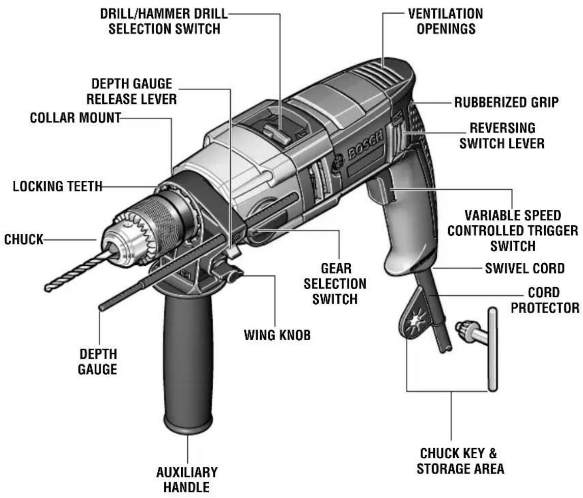
Hammer Drill
FIG. 1
text_image
DRILL/HAMMER DRILL SELECTION SWITCH DEPTH GAUGE RELEASE LEVER COLLAR MOUNT LOCKING TEETH CHUCK DEPTH GAUGE AUXILIARY HANDLE VENTILATION OPENINGS RUBBERIZED GRIP REVERSING SWITCH LEVER VIGEL CORD CORD PROTECTOR WING KNOB GEAR SELECTION SWITCH VARIABLE SPEED CONTROLLED TRIGGER SWITCH CHUCK KEY & STORAGE AREA| Model number HD | 18-2 |
| No load speed 1 n | 0 0-1,200/min |
| No load speed 2 n | 0 0-3,200/min |
| Impact rate 1 0-19 | 200 BPM |
| Impact rate 2 0-51 | 200 BPM |
| Chuck capacity 1/2" | |
| Drilling capacities | ||
| Low Speed (#1) | High Speed (#2) | |
| Concrete / Masonry | 3/4" 5/8" | |
| Steel | 1/2" 1/4" | |
| Wood | 1-9/16" 1" | |
NOTE: For tool specifications refer to the nameplate on your tool.
Assembly
WARNING
Disconnect the plug from the power source
before making any assembly, adjustments or changing accessories. Such preventive safety measures reduce the risk of starting the tool accidentally.
INSERTING BIT
For small bits, open jaws enough to insert the bit up to the flutes. For large bits, insert the bit as far as it will go. Center the bit as you close the jaws by hand. This positions the bit properly, giving maximum contact between the chuck jaws and the bit shank.
To tighten chuck, insert key into each of the three key holes in succession and tighten
clockwise firmly. The chuck can be released by using one hole only (Fig. 2).
FIG. 2
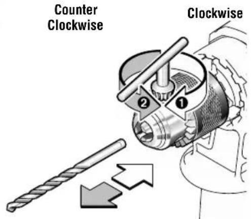
text_image
Counter Clockwise ClockwiseAUXILIARY HANDLE
The tool must be supported with the auxiliary handle, which can be swiveled and locked into 12 positions 360° around the collar mount.
To reposition and/or swivel the handle, rotate wing knob counterclockwise and push handle forward until it disengages from locking teeth in the collar mount, move handle to the desired position and push handle inward until it engages into desired position, then securely tighten wing knob (Fig. 3).
DEPTH GAUGE
Your drilling depth can be pre-set and/or repeated by using the depth gauge.
Setting depth: After the auxiliary handle is installed, make sure the accessory has been fully inserted into the chuck before setting the depth gauge (Fig. 3).
To adjust depth, push down on the depth gauge release lever, slide the depth gauge to
desired depth and release pressure on lever to lock the depth gauge in place (Fig. 3).
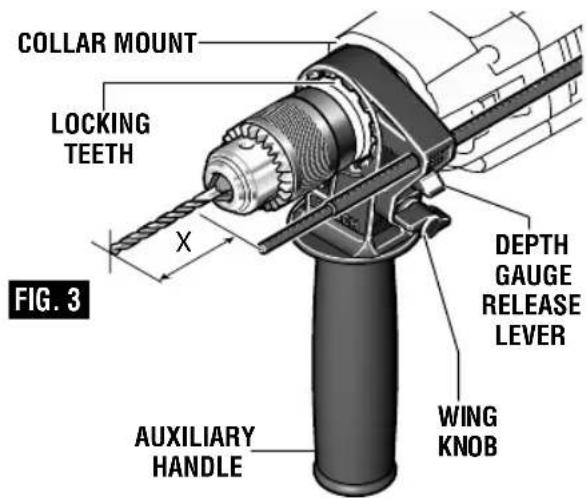
text_image
COLLAR MOUNT LOCKING TEETH X FIG. 3 DEPTH GAUGE RELEASE LEVER WING KNOB AUXILIARY HANDLEOperating Instructions
VARIABLE SPEED CONTROLLED TRIGGER SWITCH
be adjusted from the minimum to maximum nameplate RPM by the pressure you apply to the
Your tool is equipped with a variable speed trigger trigger. Apply more pressure to increase the switch. The tool can be turned "ON" or "OFF" by speed and release pressure to decrease speed squeezing or releasing the trigger. The speed can (Fig. 1).
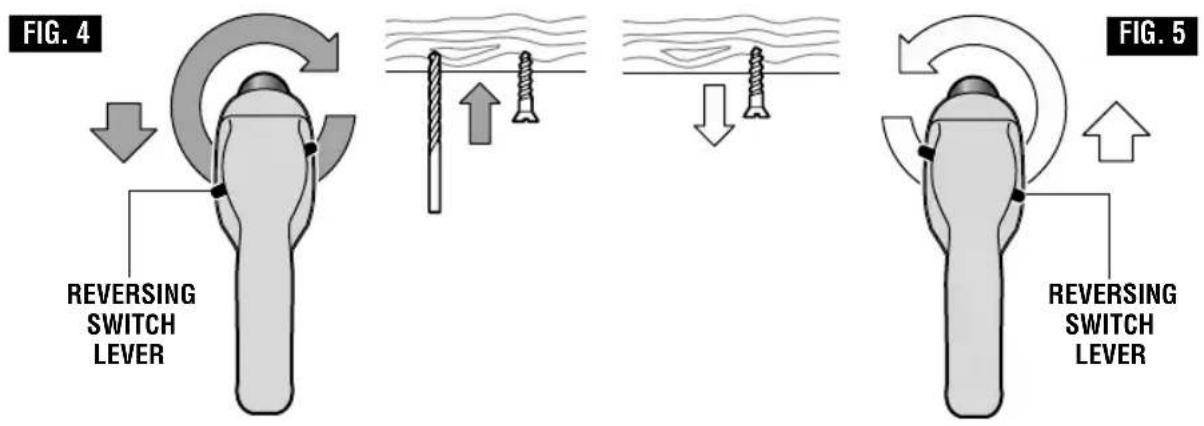
REVERSING SWITCH LEVER
This tool is equipped with a rotating brush reversing system. This results in longer tool life while maximizing power in both forward and reverse directions. The reverse switch can be operated from either the right or left side of the tool.
FOR FORWARD ROTATION: slide switch to arrow marked forward (Fig. 4).
FOR REVERSE ROTATION: slide the slide switch to arrow marked reverse. NOTE: Tool will not operate in middle position (Fig. 5).
text_image
FIG. 4 REVERSING SWITCH LEVER FIG. 5 REVERSING SWITCH LEVERDRILL/HAMMER DRILL SELECTION SWITCH
The selector switch allows the tool to be set for various drilling/hammer drilling applications. Move the selector switch right or left depending on the below applications (Fig. 1).
CAUTION Do not operate the selection switch until the
tool comes to a complete stop. Shifting during rotation of the chuck can cause damage to the tool.
Drill only action: For drilling in woods, metals, plastics or other non concrete materials.

Drill with hammer action: For drilling in masonry, asphalt, tile or other similar hard materials.
GEAR SELECTION DIAL
Gear selection: The proper gear selection is directly related to the speed and torque required for various jobs. The following should be adhered to when selecting the proper gear:
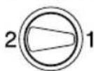
Speed 1 = low speed with high torque

Speed 2 = high speed with low torque
Changing gears: Change gear position only with the motor at a complete standstill. To change gears rotate the gear selection dial. If you have difficulties changing from one gear to the other, turn the chuck by hand until the gears engage (Fig. 1).
CHUCK KEY & STORAGE AREA
Your tool is equipped with a chuck key that is conveniently located on the cord protector
where it is always handy and unlikely to get lost or misplaced.
Operating Tips
You will extend the life of your bits and do neater work if you always put the bit in contact with the work before pulling the trigger. During the operation, hold the tool firmly and exert light, steady pressure. Too much pressure at low speed will stall the tool. Too little pressure will keep the bit from cutting and cause excess friction by sliding over the surface. This can be damaging to both tool and bit.
DRILLING WITH VARIABLE SPEED
The trigger controlled variable speed feature will eliminate the need for center punches in hard materials. The variable speed trigger allows you to slowly increase RPM. By using a slow starting speed, you are able to keep the bit from “wandering”. You can increase the speed as the bit “bites” into the work by squeezing the trigger.
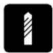
DRILL BITS
Always inspect drill bits for excessive wear. Use only bits that are sharp and in good condition.
TWIST BITS: Available with straight and reduced shanks for wood and light duty metal drilling. High speed bits cut faster and last longer on hard materials.
CARBIDE TIPPED BITS: Used for drilling stone, con crete, plaster, cement and other unusually hard nonmetals. Use continuous heavy feed presure when employing carbide tip bits.
DRILLING WOOD
Be certain workpiece is clamped or anchored firmly. Always apply pressure in a straight line with the drill bit. Maintain enough pressure to keep the drill "biting".
When drilling holes in wood, twist bits can be used. Twist bits may overheat unless pulled out frequently to clear chips from flutes.
Use a “back-up” block of wood for work that is likely to splinter, such as thin materials.
You will drill a cleaner hole if you ease up on the pressure just before the bit breaks through the wood. Then complete the hole from the back side.
DRILLING METAL
There are two rules for drilling hard materials. First, the harder the material, the greater the pres sure you need to apply to the tool. Second, the harder the material, the slower the speed. Here are a couple of tips for drilling in metal. Lubri cate the tip of the bit occasionally with cutting oil except when drilling soft metals such as alu minum, cop per or cast iron. If the hole to be drilled is fairly large, drill a smaller hole first, then enlarge to the required size, it's often faster in the long run. Main tain enough pressure to assure that the bit does not just spin in the hole. This will dull the bit and greatly shorten its life.
DRILLING MASONRY
Use carbide-tipped masonry bit for cinder block, mortar, common brick, soft stone and other materials. The amount of pressure to be used is dependent upon the type of material being drilled. Soft materials require less pressure while the hard materials need more pressure to prevent the drill bit from spinning.
Dust Extraction
For selection of dust collection systems and operating instructions, see the Operating / Safety Instructions for 'Dust Extraction
Attachments for Hammers and Hammer Drills' included with your tool or with the dust extraction attachment.
Maintenance
Service
WARNING
Preventive maintenance performed by
unauthorized per so n nel may result in misplacing of internal wires and components which could cause serious hazard. We recommend that all tool service be performed by a Bosch Factory Service Center or Autho rized Bosch Service Station.
TOOL LUBRICATION
Your Bosch tool has been properly lubricated and is ready to use. It is recommended that tools with gears be regreased with a special gear lubricant at every brush change.
CARBON BRUSHES
The brushes and commutator in your tool have been engineered for many hours of dependable service. To maintain peak efficiency of the motor, we recommend every two to six months the brush es be examined. Only genuine Bosch replace ment brushes specially designed for your tool should be used.
BEARINGS
After about 300-400 hours of operation, or at every second brush change, the bearings
should be replaced at Bosch Factory Service Center or Authorized Bosch Service Station. Bearings which become noisy (due to heavy load or very abrasive material cutting) should be replaced at once to avoid overheating or motor failure.
Cleaning
WARNING
To avoid accidents always dis connect the
tool from the power supply before cleaning or performing any main tenance. The tool may be cleaned most effectively with compressed dry air. Always wear safety goggles when cleaning tools with compressed air.
Ventilation openings and switch levers must be kept clean and free of foreign matter. Do not at tempt to clean by inserting pointed objects through openings.
CAUTION
Certain cleaning agents and sol vents damage
plastic parts. Some of these are: gasoline, carbon tetrachloride, chlorinated cleaning solvents, ammonia and house hold detergents that contain ammonia.
Extension Cords
WARNING
If an extension cord is necessary, a cord with adequate size conductors that is capable of carrying the current necessary for your tool must be used. This will prevent excessive voltage drop, loss of power or overheating. Grounded tools must use 3-wire extension cords that have 3-prong plugs and receptacles.
NOTE: The smaller the gauge number, the higher the cord capacity.
RECOMMENDED SIZES OF EXTENSION CORDS 120 VOLT ALTERNATING CURRENT TOOLS
| Tool's Ampere Rating | Cord Size in A.W.G. | Wire Sizes in mm ^2 | ||||||
| Cord Length In Feet | Cord Length In Meters | |||||||
| 25 | 50 | 100 | 150 | 15 30 | 60 | 120 | ||
| 3-6 | 18 | 16 | 16 | 14 | 0.75 | 0.75 | 1.5 | 2.5 |
| 6-8 | 18 | 16 | 14 | 12 | 0.75 | 1.0 | 2.5 | 4.0 |
| 8-10 | 18 | 16 | 14 | 12 | 0.75 | 1.0 | 2.5 | 4.0 |
| 10-12 | 16 | 16 | 14 | 12 | 1.0 | 2.5 | 4.0 | — |
| 12-16 | 14 | 12 | — | — | — | — | — | — |
Accessories
* Auxiliary handle
* Chuck key
* Depth gauge
(^* = standard equipment)
(**= optional accessories)
Robert Bosch Tool Corporation ("Seller") warrants to the original purchaser only, that all BOSCH portable and benchtop power tools will be free from defects in material or workmanship for a period of one year from date of purchase. SELLER'S SOLE OBLIGATION AND YOUR EXCLUSIVE REMEDY under this Limited Warranty and, to the extent permitted by law, any warranty or condition implied by law, shall be the repair or replacement of parts, without charge, which are effective in material or workmanship and which have not been misused, carelessly handled, or misrepaired by persons other than Seller or Authorized Service Station. To make a claim under this Limited Warranty, you must return the complete portable or benchtop power tool product, transportation prepaid, to any BOSCH Factory Service Center or Authorized Service Station. For Authorized BOSCH Power Tool Service Stations, please refer to your phone directory.
THIS LIMITED WARRANTY DOES NOT APPLY TO ACCESSORY ITEMS SUCH AS CIRCULAR SAW BLADES, DRILL BITS, ROUTER BITS, JIGSAW BLADES, SANDING BELTS, GRINDING WHEELS AND OTHER RELATED ITEMS.
ANY IMPLIED WARRANTIES SHALL BE LIMITED IN DURATION TO ONE YEAR FROM DATE OF PURCHASE. SOME STATES IN THE U.S., SOME CANADIAN PROVINCES DO NOT ALLOW LIMITATIONS ON HOW LONG AN IMPLIED WARRANTY LASTS, SO THE ABOVE LIMITATION MAY NOT APPLY TO YOU.
IN NO EVENT SHALL SELLER BE LIABLE FOR ANY INCIDENTAL OR CONSEQUENTIAL DAMAGES (INCLUDING BUT NOT LIMITED TO LIABILITY FOR LOSS OF PROFITS) ARISING FROM THE SALE OR USE OF THIS PRODUCT. SOME STATES IN THE U.S. AND SOME CANADIAN PROVINCES DO NOT ALLOW THE EXCLUSION OR LIMITATION OF INCIDENTAL OR CONSEQUENTIAL DAMAGES, SO THE ABOVE LIMITATION OR EXCLUSION MAY NOT APPLY TO YOU.
THIS LIMITED WARRANTY GIVES YOU SPECIFIC LEGAL RIGHTS, AND YOU MAY ALSO HAVE OTHER RIGHTS WHICH VARY FROM STATE TO STATE IN THE U.S., PROVINCE TO PROVINCE IN CANADA AND FROM COUNTRY TO COUNTRY.
THIS LIMITED WARRANTY APPLIES ONLY TO PORTABLE AND BENCHTOP ELECTRIC TOOLS SOLD WITHIN THE UNITED STATES OF AMERICA, CANADA AND THE COMMONWEALTH OF PUERTO RICO. FOR WARRANTY COVERAGE WITHIN OTHER COUNTRIES, CONTACT YOUR LOCAL BOSCH DEALER OR IMPORTER.
GARANTIE LIMITÉE DES OUTILS ÉLECTRIQUES PORTATIFS ET D'ÉTABLI BOSCH
© Robert Bosch Tool Corporation 1800 W. Central Road Mt. Prospect, IL 60056-2230
Exportado por: Robert Bosch Tool Corporation Mt. Prospect, IL 60056-2230, E.U.A.
text_image
Black and white barcode image with vertical lines and dots, no readable text or symbols2610048705


