
KM 120250 R D Classic - Sweeper Kärcher - Free user manual and instructions
Find the device manual for free KM 120250 R D Classic Kärcher in PDF.



| Brand | Kärcher |
| Model | KM 120250 R D Classic |
| Product type | Self-propelled thermal sweeper |
| Usage | Cleaning of industrial surfaces (parking lots, warehouses, sidewalks) |
| Dimensions (L × W × H) | 2082 × 1250 × 1450 mm |
| Empty weight | 880 kg |
| Maximum permissible weight | 1329 kg |
| Engine | Yanmar 3TNV76A 3-cylinder diesel engine, 15.8 kW (21.5 hp) |
| Fuel tank capacity | 16 L (diesel) |
| Sweeping width (with side brushes) | 1200 mm |
| Sweeping width (without side brushes) | 900 mm |
| Dust bin volume | 250 L |
| Forward speed | 9 km/h |
| Maximum incline | 18% (direction of travel) |
| Filtration system | Dust filter with manual cleaning |
| Tires front/rear | 15-4.5x8 (solid rubber) |
| Parking brake | Yes, mechanical |
| Seat safety contact | Yes (stops if driver leaves seat) |
| Routine maintenance | Daily check of fluid levels, brushes, filters |
| Warranty | According to distributor conditions |
Frequently Asked Questions - KM 120250 R D Classic Kärcher
User questions about KM 120250 R D Classic Kärcher
0 question about this device. Answer the ones you know or ask your own.
Ask a new question about this device
Download the instructions for your Sweeper in PDF format for free! Find your manual KM 120250 R D Classic - Kärcher and take your electronic device back in hand. On this page are published all the documents necessary for the use of your device. KM 120250 R D Classic by Kärcher.
USER MANUAL KM 120250 R D Classic Kärcher
1 Hydraulic pumps 2 Key
3 Nut
Director Regulatory Affairs & Certification
H. Jenner Chairman of the Board of Ma
71364 Winnenden (Germany)
Tel.: +49 7195 14-0
Fax: +49 7195 14-2212
Winnenden, 2020/01/01
General notes EN 1
Environmental protection EN 1
Warranty EN 1
Accessories and Spare Parts EN 1
Symbols in the operating instructions EN 1
Symbols on the machine EN 1
Symbols on the machine
Proper use. EN 2
Foreseeable misuse. EN 2
Suitable surfaces. EN 2
Safety instructions EN 2
Safety instructions concern
ing the operation. EN 2
Safety information concerning
the driving operation. EN 2
Appliances with combustion
engine EN 2
Appliances with high empty
ing system. EN 2
Devices with overhead guard EN 2
Safety information concerning
the transport of the appliance EN 3
Safety information concerning
maintenance and care . . EN 3
Function. EN 3
Unloading tips EN
Operating and Functional Ele
ments. EN 4
Illustration of sweeper.. EN 4
Operating field EN 4
Pedals EN 4
Indicator lamps and display EN 4
Before Startup EN 5
Lock/ release parking brake EN 5
Moving sweeper without en
gaging self-propulsion . . EN 5
Start up EN 5
General notes EN 5
Inspection and maintenance
work EN5
Refuelling. EN 5
Operation. EN 5
Adjusting driver's seat.. EN 5
Starting the machine . . . EN 5
Drive the machine . . . . EN 5
Sweeping mode EN 6
Emptying waste container EN 6
Turn off the appliance . . EN 6
Transport. EN7
Storage/decommissioning . . . EN 7
Care and maintenance . EN 7
General notes EN 7
Cleaning. EN 7
Maintenance intervals.. EN 7
Maintenance Works . . . EN 7
Troubleshooting. EN 13
Technical specifications. . EN 14
EU Declaration of Conformity. EN 15
Please read and comply with these original instructions prior
to the initial operation of your appliance and store them for later use or subsequent owners.
General notes
Your sales outlet should be informed about any transit damage noted when unpacking the product.
- Warning and information plates on the machine provide important directions for safe operation.
- In addition to the information contained in the operating instructions, all statutory safety and accident prevention regulations must be observed.
Environmental protection

The packaging material can be recycled. Please do not throw the packaging material into household waste; please send it for recycling.

Old appliances contain valuable materials that can be recycled. Please arrange for the proper recycling of old appliances. Please dispose your old appliances using appropriate collection systems.
Engine oil, diesel and petrol must not be released into the environment. Protect the ground and dispose of used oil in an environmentally responsible way.
Notes about the ingredients (REACH)
You will find current information about the ingredients at:
www.kaercher.com/REACH
Warranty
The warranty terms published by the relevant sales company are applicable in each country. We will repair potential failures of your appliance within the warranty period free of charge, provided that such failure is caused by faulty material or defects in manufacturing. In the event of a warranty claim please contact your dealer or the nearest authorized Customer Service center. Please submit the proof of purchase.
Accessories and Spare Parts
△DANGER
To avoid risks, all repairs and replacement of spare parts may only be carried out by authorized customer service personnel.
- Only use accessories and spare parts which have been approved by the manufacturer. The exclusive use of original accessories and original spare parts ensures that the appliance can be operated safely and trouble free.
- For additional information about spare parts, please go to the Service section at www.kaercher.com.
Symbols in the operating
instructions
DANGER
Warns about immediate danger which can lead to severe injuries or death.
WARNING
Warns about possible danger which could lead to severe injuries or death.
CAUTION
Points out a possibly dangerous situation which can lead to light injuries or property damage.
ATTENTION
Pointer to a possibly dangerous situation, which can lead to property damage.
Symbols on the machine
| Risk of burns on account of hot surfaces! Allow the ex-haust to cool down sufficient-ly before starting work on the machine. | |
| Always use appropriate gloves while working on the device. | |
| Risk of getting squeezed on account of getting jammed between vehicle parts. | |
| Risk of injury on account of moving parts. Do not reach in. | |
| Risk of fire. Do not vacuum up any burning or glowing objects. | |
| Chain pick-up / crane point | |
| Intake points for the jack | |
| Maximum decline of ground when driving with the waste container raised. | |
| The gradient in the direction of travel should not exceed 18%. | |
| Risk of damage! Do not rinse out the dust fil-ter. |
Proper use
The sweeper is intended for cleaning floor surfaces for commercial use and e.g. for the following fields of application:
Car parks, production facilities, logistics areas, hotel, retail industry, storage areas, walkways. Use this sweeper only as directed in these operating instructions.
Any use extending beyond this is not considered as proper use. The manufacturer is not liable for any losses resulting from this; the user alone bears the risk for this.
The machine may not be modified. The sweeper is only suitable for use on the types of floor areas specified in the operating instructions. The machine may only be operated on the surfaces approved by the company or its authorised representatives. The following applies in general: Keep highly-flammable substances away from the appliance (danger of explosion/fire).
Foreseeable misuse
-> Never vacuum up explosive liquids, combustible gases or undiluted acids and solvents. This includes petrol, paint thinner or heating oil which can generate explosive fumes or mixtures upon contact with the suction air. Acetone, undiluted acids and solvents must also be avoided as they can harm the materials on the machine. -> Never sweep/vacuum up reactive metal dusts (e.g. aluminium, magnesium, zinc), as they form explosive gases when they come in contact with highly alkaline or acidic detergents. -> Do not sweep/vacuum up any burning or glowing objects. The appliance is not suitable for sweeping off hazardous substances. The appliance should not be used in closed rooms. The machine may not be used or stored in hazardous areas. It is not allowed to use the appliance in hazardous locations. It is strictly prohibited to take co-passengers. Pushing/pulling or transporting objects by means of this appliance is prohibited.
Suitable surfaces
Asphalt Industrial floor Screed Concrete Paving stones
Safety instructions
Safety instructions concerning the operation
-> (Applicable for Finland only) The device may not be used at low ambient temperatures (below 0°C) if it is equipped with a PVC hose line. Contact Kärcher if should have questions regarding your device. The machine with working equipment must be checked to ensure that it is in proper working order and is operating safely prior to use. Otherwise, the appliance must not be used. If the appliance is used in hazardous areas (e.g. filling stations) the corresponding safety provisions must be observed. It is not allowed to use the appliance in hazardous locations.
△DANGER
Risk of injury!
Do not use the appliance without an overhead guard in areas where the operator might get hit by falling objects. The operator must use the appliance properly. The person must consider the local conditions and must pay attention to third parties, in particular children, when working with the appliance. It is important to follow all safety instructions, rules and regulations applicable for driving motor vehicles. Prior to starting work, the operator must ensure that all protective devices are properly installed and function correctly. The operator of the appliance is liable for accidents with other individuals or their property. Ensure that the operator wears tight-fitting clothes. Wear sturdy shoes and avoid wearing loose-fitting clothes. Check the immediate vicinity prior to starting (e.g. children). Ensure sufficient visibility! Never leave the machine unattended so long as the engine is running. The operator may leave the appliance only when the engine has come to a standstill, the appliance has been protected against accidental movement, and the key has been removed. Please remove the key, when not in use, to avoid unauthorized use of the appliance. The appliance may only be used by persons who have been instructed in handling the appliance or have proven qualification and expertise in operating the appliance or have been explicitly assigned the task of handling the appliance. This appliance is not intended for use by persons (including children) with limited physical, sensoric or mental capacities or lack of experience and/or skills, unless such persons are accompanied and supervised by a person in charge of their safety or if they received precise
instructions on the use of this appliance. Children should be supervised to prevent them from playing with the appliance.
CAUTION
Risk of damage! Do not sweep up straps, strings or wires as these may wrap around the brush roller.
Safety information concerning the driving operation
DANGER
Risk of injury! Verify the stability of the ground prior to driving on it.
DANGER
Risk of accident, risk of injury!
The travel speed must be adapted to the existing conditions. Danger of tipping if gradient is too high. The gradient in the direction of travel should not exceed 18%. Danger of tipping on unstable ground. Only use the machine on sound surfaces.
Danger of tipping with excessive sideways tilt. The gradient perpendicular to the direction of travel should not exceed 10%.
Appliances with combustion engine
Do not use the device at elevations of over 1200m
Danger
Risk of injury!
Do not close the exhaust. Do not bend over the exhaust or touch it (risk of burns). Do not touch the drive motor (risk of burns). Exhaust gases are poisonous and hazardous to health, do not inhale them. The engine requires approx. 3-4 seconds to come to a standstill once it has been switched off. During this time, stay well clear of the working area.
Appliances with high emptying system
DANGER
Risk of injury!
When working on the high emptying system, completely lift and secure the waste container. Perform the safeguarding only from outside the hazard zone.
Devices with overhead guard
NOTICE
The overhead guard (optional) protects the driver against larger falling objects. However, it does not provide rollover protection!
Check the overhead guard for damage daily. If the overhead guard, as well as individual elements, should be damaged, replace the entire overhead guard. Any modification of the overhead guard and installation of elements, components and assemblies other than those approved by Karcher is not permitted
and may limit the function of the overhead guard.
Safety information concerning the transport of the appliance
Observe the net weight (transport weight) of the device during transport on trailers or vehicles. Disconnect the battery and securely fasten the device for transport.
Safety information concerning maintenance and care
First switch off the appliance and remove the key before performing any cleaning or maintenance tasks on the appliance, replacing parts or switching over to another function. Always disconnect the battery when working on the electrics. To do this, first disconnect the negative terminal and then the positive terminal. Reconnection is performed in reverse sequence. Connect the positive terminal first, then connect the negative terminal. Do not clean the appliance with a water hose or high-pressure water jet (danger of short circuits or other damage). Maintenance work may only be carried out by approved customer service outlets or experts in this field who are familiar with the respective safety regulations. Please observe the local safety regulations regarding portable commercially used appliances. Always use appropriate gloves while working on the device.
Function
The sweeper operates using the sweepshovel principle.
- The rotating roller brush moves the dirt directly into the waste container.
- The side brush cleans the corners and edges of the surface and moves dirt and debris into the path of the roller brush.
- The fine dust is sucked in via the dust filter through the suction blower.
Unloading tips
DANGER
Risk of personal injury or damage!
Observe the weight of the appliance when you load it! Do not use a fork lift, the appliance could get damaged.
Net weight (transport weight) 880 kg*
- If upgrade kits are installed, the weight is respectively higher. Use a suitable ramp or a crane to load the appliance! Observe when using a ramp: Ground clearance 70 mm. If the machine is delivered on a pallet, you must create an unloading ramp using the boards provided.
You will find the instructions for this procedure on page 2 (inside of cover). Important instruction: every board must be attached with at least 2 screws.
Operating and Functional Elements
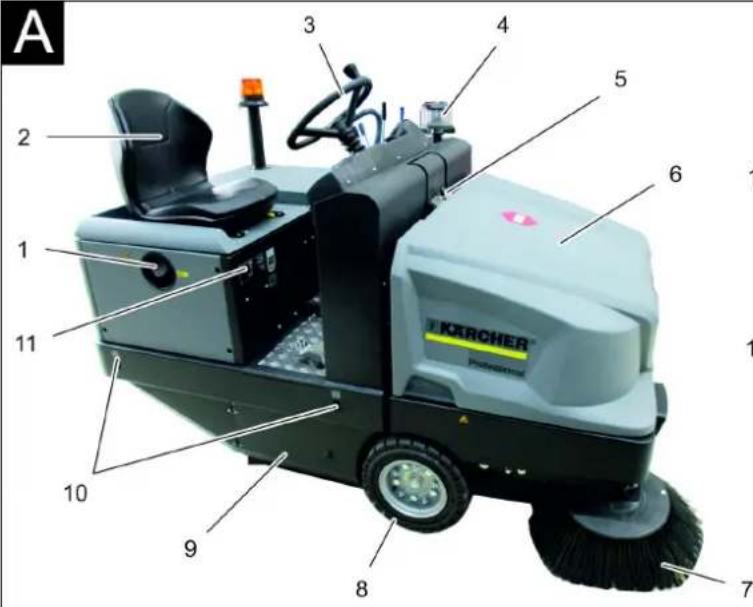
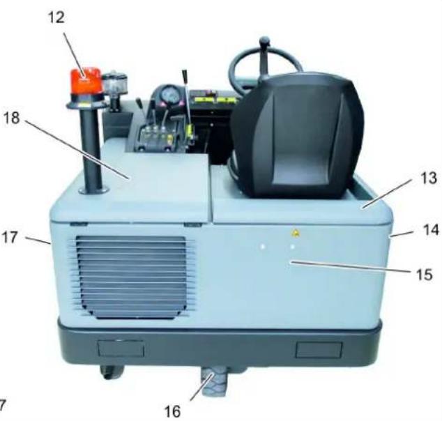
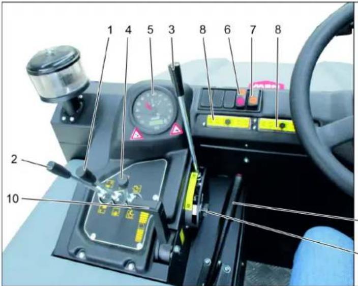
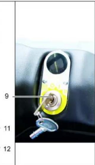
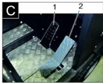
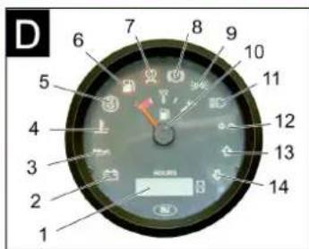
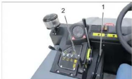
Illustration of sweeper Operating field
Illustration A
1 Tank lid 2 Seat (with seat contact switch) 3 Steering wheel 4 Centrifugal separator 5 Lock of appliance hood 6 Cover 7 Side brush, right 8 Front wheel 9 Roller brush access 10 Lashing point 11 Nameplate 12 Beacon lamp 13 Appliance cover right side 14 Cover, right 15 Tail panel 16 Rear wheel 17 Cover, left 18 Bonnet left side (engine bonnet)
Illustration 6
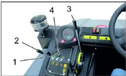
1 Roller brush and side brush control lever
Lever
Lever forwards: Switches the roller brush on and lowers and switches the side brushes on.
Lever backwards: Switches the roller brush on
2 Control lever waste container
Raise/ lower waste container
3 Roller brush control lever
Raises and lowers the roller brush
4 Control lever container flap
Open/close container lid
5 Indicator lamps and display
6 Switch blower and filter cleaning Position centred: Filter cleaning and blower off
Rear position: Blower on
Front position: Filter cleaning on
7 Horn switch 8 Fuses 9 Ignition lock
Filament symbol: Pre-heat
Position 0: Switch off engine
Position 1: Ignition on
Position 2: Start the engine
10 Motor speed adjustment Gas lever 11 Parking brake 12 Roller brush wear adjustment / sweeping area setting
Pedals
Illustration
1 Brake pedal 2 Accelerator pedal forward / reverse
Indicator lamps and display
Illustration
1 Operating hour counter 2 Charge warning lamp 3 Oil pressure warning lamp 4 Cooling water temperature warning lamp 5 Motor suction air 6 Warning lamp fuel reserve 7 Preglow indicator light 8 Indicator lamp (not connected)
9 Indicator light parking light/low beam (option) 10 Tank indicator 11 Without function, only illuminates during start-up of the motor (self-test) 12 Without function 13 Without function 14 Without function
Before Startup
Lock/ release parking brake
Loosen parking brake; press brake pedal at the same time. Activate the parking brake; press brake pedal at the same time.
Moving sweeper without engaging self-propulsion
Note
This procedure is necessary if the device needs to be pushed off the palette or towed away, or must be moved onto a transport vehicle without its own drive.
ATTENTION
Do not move the machine for long distances without engaging self-propulsion; a speed of 10 km/h should not be exceeded.
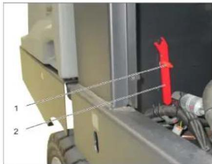
1 Screw 2 Key Unscrew the screw. Remove the spanner.
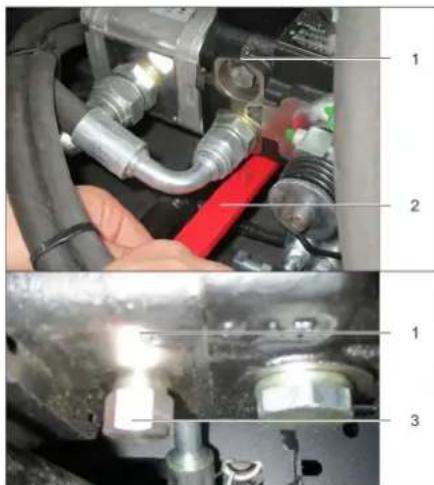
1 Hydraulic pump
2 Key 3 Nut Loosen the nut using the spanner (open freewheel) until the device can be pushed. IMPORTANT: Once pushed, reclose the nut (close freewheel = drive position).
Start up
General notes
Read the operating instructions of the engine manufacturer before start-up and follow the safety instructions carefully. Park the sweeper on an even surface. Remove ignition key. Lock parking brake.
Inspection and maintenance work
Daily before starting operations
Check fill level of fuel tank. Check engine oil level. Check the filling level in the coolant expansion tank. Check the sweeping roller and the side brush for wear and wrapped belts. Check the wheels for tied up belts. Check the centrifugal separator and the air filter, clean if required. Check function of all operator control elements. Check appliance for damages. Clean the dust filter with the filter cleaning button.
Note: For description, see section on Care and maintenance.
Refuelling
△DANGER
Risk of explosion!
Only use the fuels specified in the Operations Manual. Do not refuel the machine in enclosed spaces. Smoking and naked flames are strictly prohibited. Ensure that no fuel reaches the hot open surfaces. Check fuel level via the tank indicator. Switch off engine. Open fuel filler cap. Fill in diesel. Wipe off any spilt fuel and close fuel filler cap.
Operation
Adjusting driver's seat
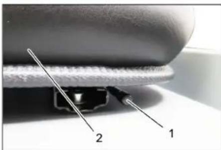
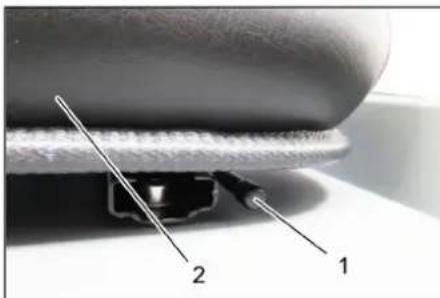
1 Lever for seat adjustment
2 Driver seat
Pull seat adjustment lever outwards. Slide seat, release lever and lock in place. Check that the seat is properly locked in position by attempting to move it backwards and forwards.
Starting the machine
Note: The machine is equipped with a seat contact switch. If the driver's seat is vacated, the machine is switched off.

1 Parking brake
2 Motor speed adjustment. Sit on the driver's seat. Lock parking brake. Engine speed adjustment - push forward by 1/3.
Pre-heat
Insert the ignition key into the ignition switch. Turn the ignition key to position "Filament".
Pre-heat lamp glows.
Start the engine
Press the brake pedal in order to start the engine. When the pre-heating lamp goes off, turn the ignition key to position "I". If the machine starts, release the ignition key.
Note: Never operate the starter motor for longer than 10 seconds. Wait at least 10 seconds before operating the starter motor again.
Drive the machine
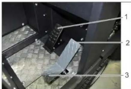
1 Brake pedal 2 Accelerator pedal, "forwards" 3 Accelerator pedal, "reverse"
Push the motor speed adjustment all the way to the front (operating speed). Press brake pedal and keep it depressed. Release parking brake.
Drive forward
Press slowly the accelerator pedal "forward".
Reverse drive
DANGER
Risk of injury!
When reversing, there must not be any risk for third parties, have somebody marshal the driver if necessary. Press slowly the accelerator pedal "reverse".
Driving method
The accelerator pedal can be used to vary the driving speed infinitely. Avoid sudden operation of the pedal as this may damage the hydraulic system. In the event of power loss on inclined surfaces, slightly reduce the pressure on the accelerator pedal.
Brakes
Release the accelerator pedal, the machine brakes automatically and stops.
Note: The braking effect can be supported by pressing the brake pedal.
Driving over obstacles
Driving over fixed obstacles which are 70 mm high or less:
Drive forwards slowly and carefully. Driving over fixed obstacles which are more than 70 mm high: Only drive over these obstacles using a suitable ramp.
Sweeping mode
ATTENTION
Do not sweep up packing strips, wire or similar objects as this may damage the sweeping mechanism.
Note: To achieve an optimum cleaning result, the driving speed should be adjusted to take specific situations into account.
Note: During operation, the dust filter should be shaken off and cleaned at regular intervals.
Note: When frequently working in areas with fine dust, the filter must be cleaned more often.
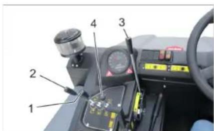
Control lever
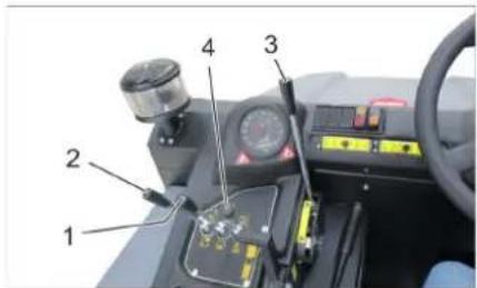
1 Roller brush and side brush control lever
2 Control lever waste container 3 Roller brush control lever 4 Control lever container flap
Roller brush and side brush control lever
Control lever (1) forwards: Switches the roller brush on and lowers and switches the side brushes on. Control lever (1) backwards: Switches the roller brush on.
Control lever waste container
Control lever waste container (2) to the front: Waste container is lowered.
Control lever waste container (2) to the back: Waste container is raised.
Control lever roller brush
Roller brush control lever (3) forwards: Raises the roller brush. Roller brush control lever (3) backwards: Lowers the roller brush.
Control lever container flap
Control lever container flap (4) to the front: The container flap of the waste container opens. Control lever container flap (4) to the back: The container flap of the waste container closes.
Sweeping dry floors
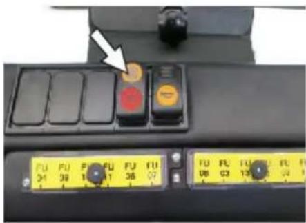
Switch on the blower. With surface cleaning:
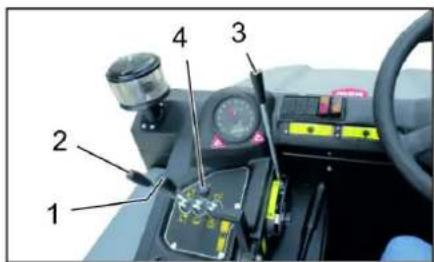
Roller brush and side brush control lever (1) backwards: Switches the roller brush on.
Roller brush control lever (3) backwards: Lowers the roller brush.
Control lever container flap (4) to the front: Container flap opens. With cleaning of side edges:
Roller brush and side brush control lever (1) forwards: Switches the roller brush on, switches the side brushes on and lowers them.
Roller brush control lever (3) backwards: Lowers the roller brush.
Sweeping damp or wet floors
Switch off the blower. For surface cleaning:
Roller brush and side brush control lever (1) backwards: Switches the roller brush on. Roller brush control lever (3) backwards: Lowers the roller brush. Control lever container flap (4) to the front: Container flap opens.
For cleaning of side edges:
Roller brush and side brush control lever (1) forwards: Switches the roller brush on, switches the side brushes on and lowers them. Roller brush control lever (3) backwards: Lowers the roller brush.
Emptying waste container
DANGER
Risk of injury!
During the emptying process, persons and animals must not stay within the swivelling range of the waste container. Danger of tipping! Place the device on an even surface during the emptying process.
WARNING
Risk of crushing!
Never reach into the rod assembly for the drainage mechanism. Do not stay under the raised container.
ATTENTION
Risk of personal injury or damage! Material of the rotating roller brush may be catapulted off during the emptying process. Keep an appropriate distance.
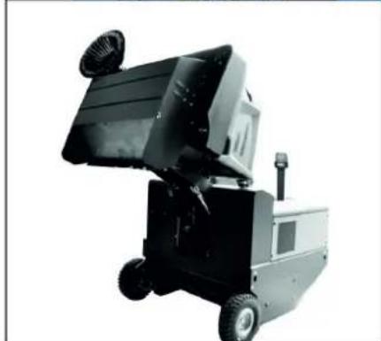
Raise the roller brush and side brushes using the control levers: Control lever 1 to middle position and control lever 3 forwards. Close the container flap, in order to do so, move the control lever (4) to the back. Raise the container flap, in order to do so, move the waste container control lever (2) to the back. Slowly drive towards the collection container. Lock parking brake. Open the container flap, in order to do so, push the container flap operating lever (4) to the front and empty the waste container. Close the container flap, in order to do so, push the container flap operating lever (4) to the back until it is tipped inwards in the end position. Release parking brake. Drive away the collection container slowly. Lower the waste container into the end position, in order to do so, move the waste container control lever (2) to the front.
Turn off the appliance
Raise the roller brush and side brushes using the control levers: Control lever 1 to middle position and control lever 3 forwards. Close the container flap, in order to do so, move the control lever (4) to the back.
Pull the motor speed adjustment all the way to the back. Press brake pedal and keep it depressed. Lock parking brake. Turn ignition key to "0" and remove it.
Transport
DANGER
Transport damage!
Observe the net weight (transport weight) of the device during transport on trailers or vehicles. When transporting in vehicles, secure the appliance according to the guidelines from slipping and tipping over. Turn ignition key to "0" and remove it. Lock parking brake. Secure the appliance at the lashing points (4x) using tension belts, ropes or chains. Secure the wheels of the machine with wheel chocks. Disconnect the battery of the sweeper during transport.
Storage/decommissioning
DANGER
Risk of injury and damage! Note the weight of the appliance in case of storage.
Park the sweeper on a level surface in a dry, frost protected area. Protect it against dust by means of covering material. Raise the roller brush and the side brushes to prevent the bristles from being damaged. Close the container flap. Turn ignition key to "0" and remove it. Lock parking brake. Lock the sweeper to ensure that it does not roll off.
Additionally observe the following points if the sweeper is not used over a longer period of time:
Change engine oil. Drain off the cooling water if frost is expected and check whether there is adequate anti-frosting agent. Clean the inside and outside of the sweeper. Disconnect battery. Charge battery and recharge it approx. every 2 months.
Care and maintenance
General notes
ATTENTION
Risk of damage!
Do not rinse out the dust filter. Maintenance work may only be carried out by approved customer service outlets or experts in this field who are familiar with the respective safety regulations. Mobile appliances used for commercial purposes are subject to safety inspections according to VDE 0701. Park the sweeper on an even surface.
Turn ignition key to "0" and remove it. Lock parking brake.
Cleaning
CAUTION
Risk of damage! Do not clean the appliance with a water hose or high-pressure water jet (danger of short circuits or other damage).
Cleaning the inside of the machine
DANGER
Risk of injury!
Wear dust mask and protective goggles. Clean machine with a cloth. Blow through machine with compressed air.
External cleaning of the appliance
Clean the machine with a damp cloth that has been soaked in mild detergent.
Note: Do not use aggressive cleaning agents.
Maintenance intervals
Note: The elapsed-time counter shows the timing of the maintenance intervals.
Maintenance by the customer
Note: Where maintenance is carried out by the customer, all service and maintenance work must be undertaken by a qualified specialist. If required, a specialised Kärcher dealer may be contacted at any time.
Daily maintenance:
Check the fill level of the fuel tank. Check the engine oil level. Check the filling level in the coolant expansion tank. Check the sweeping roller and the side brush for wear and wrapped belts. Check the fuel filter. Check the centrifugal separator and the air filter, clean if required. Check the function of all operator control elements.
Check the appliance for damages.
Weekly maintenance:
Clean the water cooler. Clean the hydraulic oil cooler. Check the hydraulic unit. Check the hydraulic oil level. Check the brake fluid status. Check the pad for wear, replace if required. Check the container lid and lubricate it.
Maintenance to be carried out every 50 operating hours:
Drain the water from the diesel/water separator.
Maintenance following wear:
Replace sealing strips. Readjust the side seals or replace them. Replace the roller brush. Replace the side brush.
Note: For description, see section on Maintenance work.
Maintenance by Customer Service
Note: In order to safeguard warranty claims, all service and maintenance work during the warranty period must be carried out by the authorised Kärcher Customer Service in accordance with the maintenance booklet.
Maintenance to be carried out after 50 operating hours:
Have the first maintenance performed by the customer service in accordance with the inspection check list.
Maintenance after 250/500/1000/1500/2000 operating hours:
Have the maintenance performed by the customer service in accordance with the inspection check list.
Maintenance Works
Preparation:
Park the sweeper on an even surface. Turn ignition key to "0" and remove it. Lock parking brake.
General notes on safety
DANGER
Risk of injury!
Always apply the safety rod when the waste container is raised. Perform the safeguarding only from outside the hazard zone.
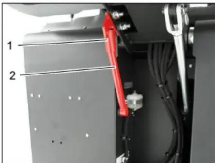
1 Holder of safety rod 2 Safety rod. Fold the safety rod for the high emptying up and insert it into the holder (secured).

Please do not release engine oil, fuel oil, diesel, or petrol into the environment. Protect the ground and dispose of used oil in an environmentally-clean manner.
Safety notes regarding the batteries
Please observe the following warning notes when handling batteries:

Observe the directions on the battery, in the instructions for use, and in the vehicle operating instructions!

Wear an eye shield!

Keep children away from acid and batteries!
| Risk of explosion! | |
| Fire, sparks, open light, and smoking not allowed! | |
| Danger of causticization! | |
| First aid! | |
| Warning note! | |
| Disposal! | |
| Pb | Do not throw the battery in the dustbin! |
DANGER
Risk of explosion!
Only use batteries with terminal cover. Restore terminal cover in the event of loss.
DANGER
Risk of explosion!
Do not place tools or similar items on the battery. Risk of short-circuit and explosion.
DANGER
Risk of injury!
Ensure that wounds never come into contact with lead. Always clean your hands after working on batteries.
DANGER
Risk of fire and explosion! Smoking and naked flames are strictly prohibited. Rooms where batteries are charged must have good ventilation because highly explosive gas is emitted during charging.
Smoking and naked flames are strictly prohibited. Rooms where batteries are charged must have good ventilation because highly explosive gas is emitted during charging.
Danger of causticization! Rinse thoroughly with lots of clear water if acid gets into the eye or comes in contact with the skin. Then consult a doctor immediately. Wash off the acid if it comes in contact with the clothes.
Installing and connecting the battery
Rinse thoroughly with lots of clear water if acid gets into the eye or comes in contact with the skin. Then consult a doctor immediately. Wash off the acid if it comes in contact with the clothes.
1 Positive terminal
Normally, the machine is equipped with a maintenance-free battery.
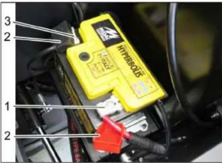
3 Negative terminal
Insert battery in battery mount. Screw on mounts on battery base. Connect pole terminal (red cable) to positive pole (+). Connect pole terminal to negative pole (-). Attach the pole covers. Check that the battery poles and pole terminals are adequately protected with pole grease.
Check and correct the fluid level of the battery (only with low-maintenance battery with cell caps)
Insert battery in battery mount. Screw on mounts on battery base. Connect pole terminal (red cable) to positive pole (+). Connect pole terminal to negative pole (-). Attach the pole covers. Check that the battery poles and pole terminals are adequately protected with pole grease.
Check and correct the fluid level of the battery (only with low-maintenance battery with cell caps)
CAUTION
Risk of damage!
Regularly check the fluid level in acid-filled batteries. Unscrew all cell caps. Take a sample from each cell using the acid tester. The acid in a fully charged battery has a specific weight of 1.28 kg/l at a temperature of 20°C. The acid in a partially discharged battery has a specific weight between 1.00 and 1.28 kg/l. The specific weight of the acid must be uniform in all cells. Put the acid sample back into the same cell. Where fluid level is too low, top up cells to the mark provided with distilled water. Then charge the battery. Screw in cell caps.
Charging battery
DANGER
Risk of injury! Comply with safety regulations on the handling of batteries. Observe the directions provided by the manufacturer of the charger.
DANGER
Risk of damage!
Charge the battery only with an appropriate charger.
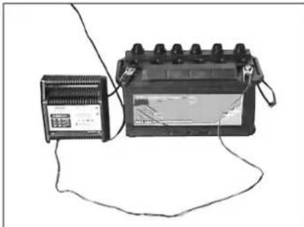
Unscrew all cell caps. (only with low-maintenance battery) Connect positive terminal cable from the charger to the positive pole connection on the battery. Connect negative terminal cable from the charger to the negative pole connection on the battery. Plug in mains connector and switch on charger. Charge battery using lowest possible level of charging current. When the battery is charged, first remove the charger from the mains and then disconnect it from the battery. Screw in cell caps. (only with low-maintenance battery)
Remove the battery
Disconnect pole terminal to negative pole (-). Disconnect pole terminal to positive pole (+). Loosen the mounts on battery base. Remove the battery from the battery holder. Dispose of the used battery according to the local provisions.
Checking the brake fluid level and topping up brake fluid
DANGER
Risk of injury!
Always apply the safety rod when the waste container is raised. Perform the safeguarding only from outside the hazard zone.
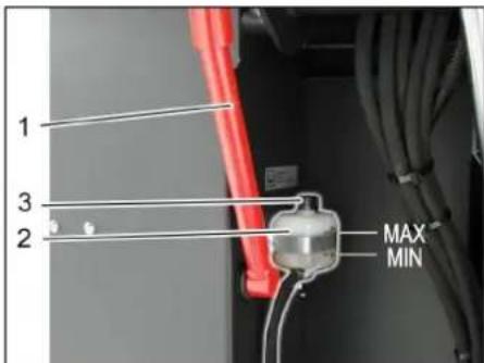
1 Holder of safety rod 2 Brake fluid container 3 Closing head Move up the waste container and secure it by means of the safety rod, see Chapter "Emptying the waste container". Check if there is enough brake fluid in the brake fluid reservoir. Note
The filling level has to be between Min. and Max.
If necessary, refill DOT brake fluid currently commercially available.
Check engine oil level and top up, if required
△DANGER
Risk of burns!
→ Allow engine to cool down. Wait for at least 5 minutes after switching off the engine before checking the engine oil fill level.
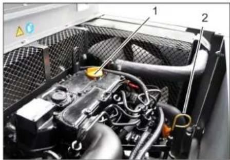
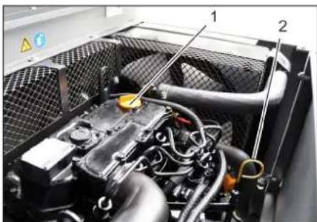
1 Oil cap (engine) 2 Oil dipstick Pull out oil dipstick. Wipe off oil dipstick and insert. Pull out oil dipstick. Read the value of the oil level. Insert the oil dip again.
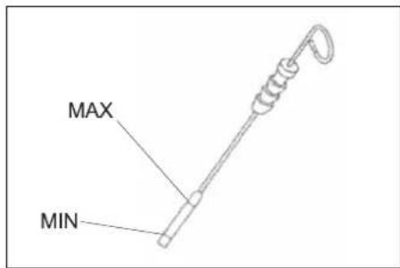
The oil level must lie between "MIN" and "MAX" marking. - Add motor oil if the oil level is below the "MIN" marking. - Do not fill oil above the "MAX" marking. → Remove oil cap. → Fill in motor oil.
For oil type refer to Chapter "Technical specifications".
→ Close oil cap. Wait at least 5 minutes. Check engine oil level.
Change the motor oil and the oil filter CAUTION
Risk of burns due to hot engine oil! → Allow engine to cool down. Prepare a collection container for at least 6 litres of engine oil. → Allow engine to cool down.

Unscrew oil drain plug. → Remove oil cap. Drain off oil.
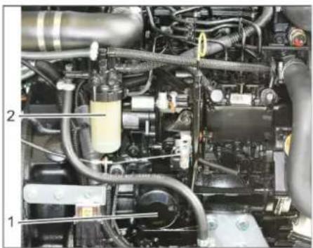
1 Engine oil filter
2 Fuel filter
Unscrew the oil filter. Clean the intake and sealing areas. Coat the washer of the new oil filter with oil before fitting it. Fit in the new oil filter and tighten it by hand. Screw in the oil drain screw along with the new washer.
Tightening torque: 25 Nm
Fill in motor oil.
For oil type and filling quantity refer to Chapter "Technical specifications".
Close oil cap. Let the motor run for approx. 10 seconds. Check engine oil level.
Check fuel filter
Check the fuel filter for soiling. Clean the fuel filter and filter casing as needed; replace the fuel filter if necessary.
Replace the fuel filter
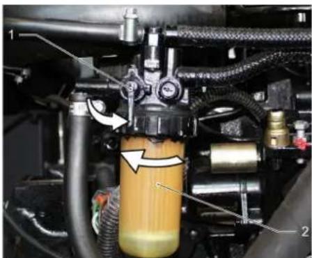
1 Fuel cock 2 Fuel filter. Close fuel cock. Unscrew the fuel filter and replace it.
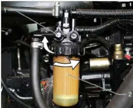
1 Fuel cock 2 Fuel filter
NOTICE
Fill the fuel filter with diesel fuel prior to installing it.
Screw the new fuel filter in. Torque the fuel filter to 20 Nm. Open fuel cock.
Draining the condensation water from the diesel water separator
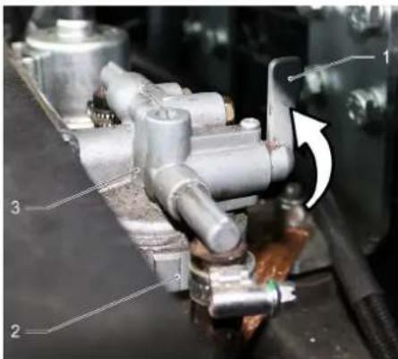
1 Fuel cock
2 Separator cup 3 Water separator
Close the fuel cock. Unscrew the separator cup and empty it. Screw on the separator cup. Open the fuel cock.
Check hydraulic oil level and refill hydraulic oil
NOTICE
The waste container must not be raised. Open the engine cover.
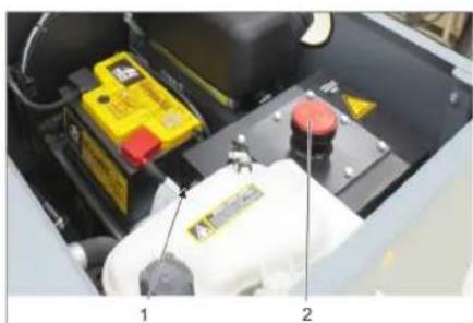
1 Hydraulic oil sight glass 2 Screw cap, oil fill opening. Check the hydraulic oil level in the sight glass. The oil level must lie between the "MIN" and "MAX" markings. Add hydraulic oil if the oil level is below the "MIN" marking.
Loosen the closing cap of the oil filling opening. Clean the filling area. Refill hydraulic oil. For oil type, refer to Chapter "Technical specifications". Replace and tighten the closing cap of the oil filling opening.
Check hydraulic unit
NOTICE
Only Kärcher Customer Service is authorised to carry out maintenance tasks on the hydraulic unit.
Lock the parking brake. Start the motor. Check all hydraulic hoses and connections and ensure that they are leak-proof.
Check coolant level 1 Coolant expansion tank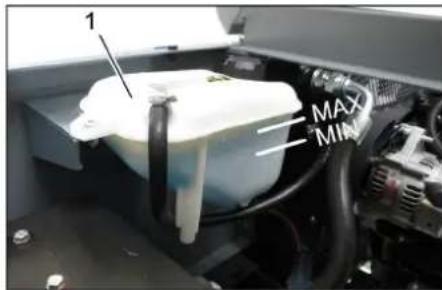
Check the filling level while the motor is cold. Check the filling level in the coolant expansion tank. The correct coolant level has to be between MIN and MAX.
Checking and cleaning water/hydraulic oil cooler
DANGER
Risk of burning and scalding!
Allow the water cooler to cool down for at least 20 minutes. The coolant level of the water cooler is checked at the coolant expansion tank. See chapter "Checking the cooling water level". Clean cooler lamella. Remove soiling by means of a soft brush, compressed air or low water pressure. Check cooler hoses and connections and ensure that they are leak-proof. Clean the fan.
Checking roller brush
Start the motor. Raise the waste container up to the end-position. Switch off engine. Lock parking brake. Use the safety bar for emptying from a height. Remove belts or cords from roller brush. Remove the safety bar. Start the motor. Lower the waste container up to the end-position. Switch off engine.
Replacing roller brush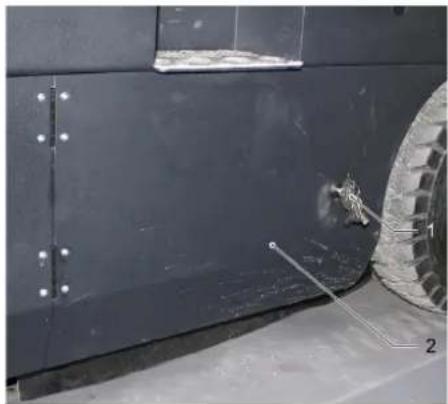
1 Key
2 Side panels
Drive the waste container up and support it with the safety rod. Open the side covers using a key.
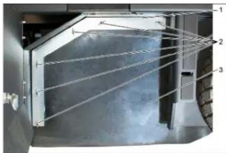
1 Holding bow
2 Wing nut
3 Side seal
Unscrew the wing nuts. Remove the retaining clamp. Flip the side seal out. Unscrew the retaining screw of the roller brush intake, and swing the intake to the outside. Pull out roller brush.
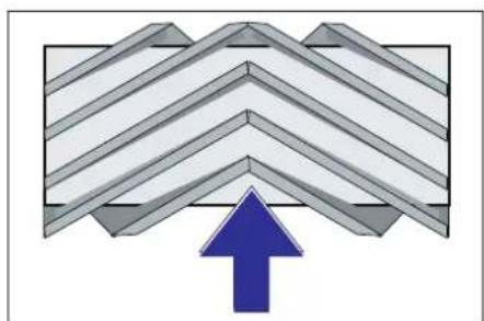
Installation position of roller brush in direction of travel (top view)
Note: When installing the new roller brush, ensure correct positioning of the bristle assembly.
Install new roller brush. The nuts of the roller brush must be inserted on the notches of the opposite crank.
Note: Once the new roller brush has been installed, the sweeping track must be readjusted.
Check and adjust roller brush sweeping track
Note: The sweeping track is factory-set to 80mm ; it is steplessly adjustable if the brush roller wears down.
Check tyre pressure. Switch off suction blower.
→ Drive sweeper on to a smooth, even surface covered with a visible layer of dust or chalk. → Roller brush and side brush control lever (1) backwards: Switches the roller brush on. Roller brush control lever (3) backwards: Lowers the roller brush. → Allow the roller brush to run for approx. 10 seconds. → Roller brush and side brush control lever (1) to middle position. Roller brush control lever (3) forwards: Raises the roller brush. Drive machine backwards. Check sweeping mirror.
The sweeping track should have an even rectangular shape which is 80 - 85mm wide.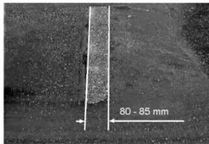
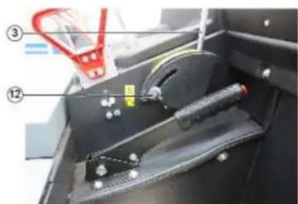
→ Undo and adjust the stop screw for wear adjustment (12). Stop screw at the top: narrow sweeping area. Stop screw at the bottom: broad sweeping area. → Tighten the stop screw again. Check the sweeping area of the roller brush again as described.
Check and adjust sweeping track of the side-brush
The side-brushes lift up. → Drive sweeper on to a smooth, even surface covered with a visible layer of dust or chalk. Lower the side brushes using the control lever and allow them to run for approx. 10 seconds. The side-brushes lift up. → Drive machine backwards. Check sweeping mirror.
The width of the sweeping track should lie between 40-50 mm.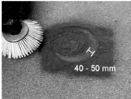
Set the sweeping track using the two adjusting screws. Check sweeping mirror.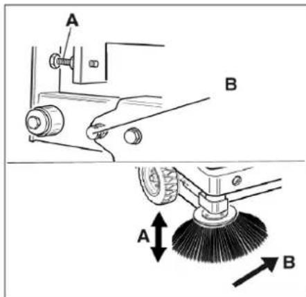
Adjust the side seals
△DANGER
Risk of injury!
Always apply the safety rod when the waste container is raised. → Perform the safeguarding only from outside the hazard zone. Drive the waste container up and secure it with the safety rod. → Fold the safety rod for the high emptying up and insert it into the holder (se-cured).
1 Holder of safety rod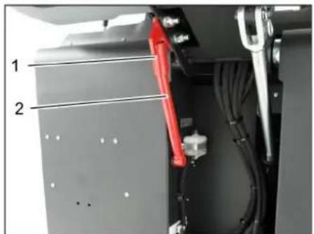
2 Safety rod
Open the side cover as described in Chapter "Replace brush roller". Release the 6 wing nuts on the side holding plate. Loosen 3 nuts (SW 13) on the front holding plate. Press the side seal down (elongated hole) until it is about 1 to 3 mm to the floor. Screw in the holding plates.
Repeat the procedure on the other side of the appliance.
Manually clean the dust filter
Switch on manual filter shake off.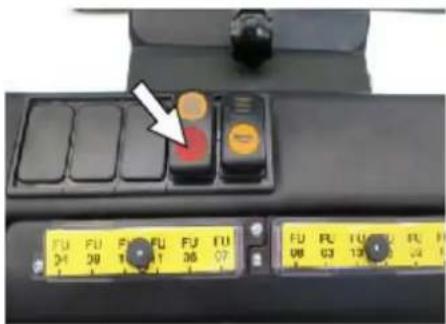
Check/replace dust filter
WARNING
Risk of injury!
Wear a dust mask when working around the dust filter. Observe safety regulations on the handling of fine particles. Clean the dust filter with the filter cleaning button. Empty waste container.
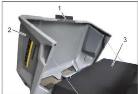
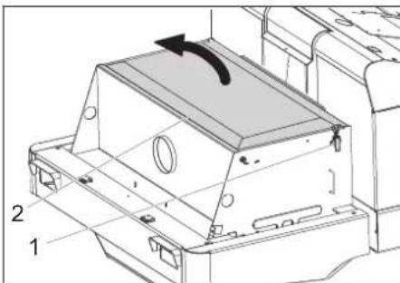
1 Lock of appliance hood 2 Cover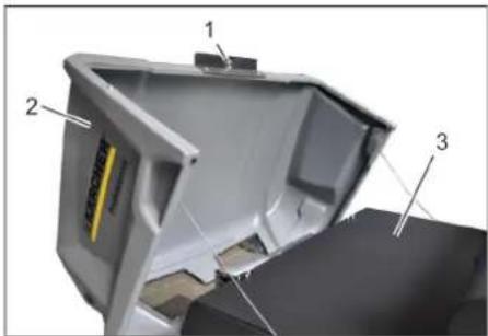
3 Filter cover
Open the lock, remove the star grip screw to do this. Fold cover forwards.
1 Lock, filter cover (2x) 2 Filter cover. Open the lock. Open filter cap.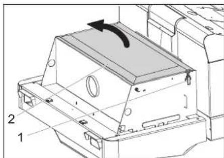
1 Cross struts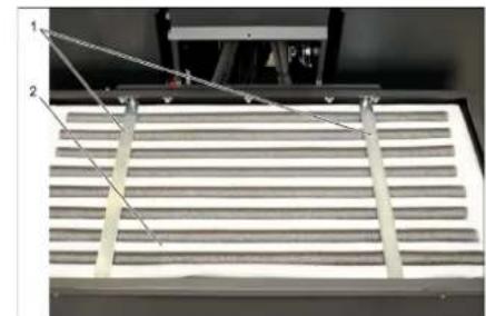
2 Dust filter
Check the dust filter, clean or replace if necessary.
Note
The dust filter may only be replaced by Karcher Customer Service. Insert and lock the filter cover.
Check and adjust the V-Belt
The V-Belt must deflect approx. 7-9 mm at a pressure of 10 kg. Get the V-belt tension adjusted by an authorized customer service.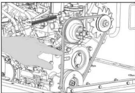
Check air filter and replace, if necessary
1 Lock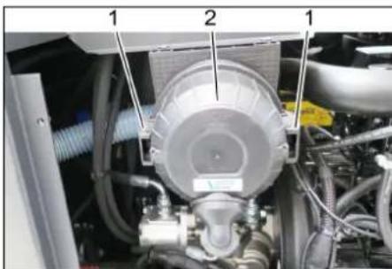
2 Air filter housing
Remove side panel. Remove the air filter housing. Replace the air filter insert. Note: Installation position with blowout opening pointing down (see illustration).
Clean the centrifugal separator
1 Wing nut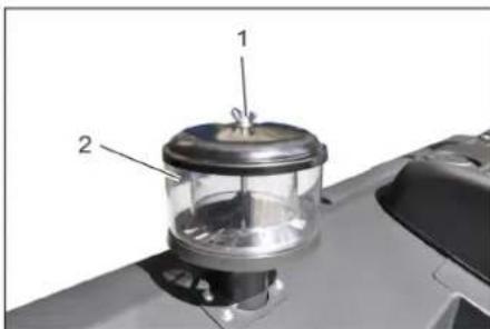
2 Centrifugal separator. Unscrew the wing nut from the centrifugal separator. Clean the centrifugal separator.
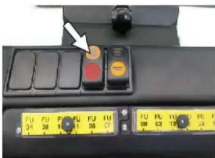
Replacing fuses
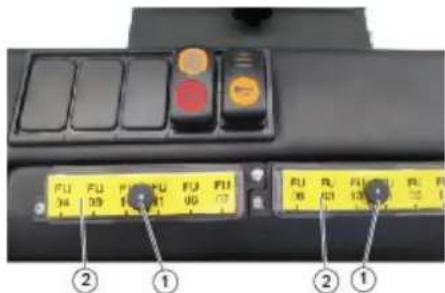
1 Lock nut
2 Cover fuse box
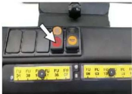
Unscrew the knurled nut. Open the cover on the fuse box. Check the fuses. Replace defective fuses.
Note: Only use fuses with identical safety ratings.
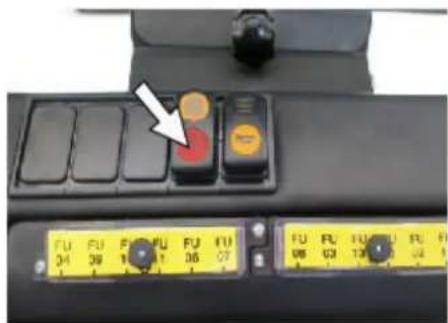
Note: The fuse FU 01 is located in the engine compartment.
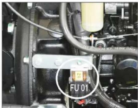
| FU 01* Main fuse 60 A | |
| FU 02 Horn 25 A | |
| FU 03 Safety relay Multifunction display | 10 A |
| FU 04 Beacon lamp 5 A | |
| FU 05 Safety relay Time delay | 25 A |
| FU 06 Driver cabin (optional) Wiper | 10 A |
| FU 07 Fuel pump 10 A | |
| FU 08 Starter 3 A | |
| FU 09 Left lighting 7.5 A | |
| FU 10 Right lighting 7.5 A | |
| FU 11 Working light 10 A | |
| FU 12 Vibrator system Suction blower | 25 A |
| FU 13 Backup signal 5 A |
- These fuses may only be changed by Customer Service, as it is necessary to check the device for potential faults.
Troubleshooting
| Fault Remedy | |
| Appliance cannot be started | Sit on the driver seat, the seat contact switch gets activated. |
| Press the brake pedal in order to start the engine. | |
| Charging or replacing battery | |
| Fill in fuel,deaerate the fuel system | |
| Change fuel filter | |
| Check fuel pipes,connections and joints and maintain them if required | |
| Inform Kärcher Customer Service. | |
| Engine is running erratically | Clean air filter or change filter cartridge. |
| Check fuel pipes,connections and joints and maintain them if required | |
| Inform Kärcher Customer Service. | |
| Engine is overheated Refill coolant | |
| Rinse cooler | |
| Tighten V-Belt | |
| Inform Kärcher Customer Service. | |
| Engine is running but machine is only moving slowly or is not moving at all | Release parking brake |
| Close freewheel (drive position) | |
| Move the gas lever all the way to the front (high speed). | |
| Check for trapped ribbons and strings. | |
| Inform Kärcher Customer Service. | |
| Whistling sound in the hydraulic system | Refill hydraulic fluid |
| Inform Kärcher Customer Service. | |
| Brushes are rotating slowly or not at all | Move the gas lever all the way to the front (high speed). |
| Check for trapped ribbons and strings. | |
| Inform Kärcher Customer Service. | |
| Too little or no suction power in the brush area | Check dust filter,clean or replace. |
| Inform Kärcher Customer Service. | |
| Dust gathers in the machine Adjust | the side seals |
| Switch on blower | |
| Check dust filter,clean or replace. | |
| Replace filter washers | |
| Open the container flap of the waste container. | |
| Inform Kärcher Customer Service. | |
| Sweeping unit does not pick up waste | Empty waste container |
| Check dust filter,clean or replace. | |
| Replacing roller brush | |
| Adjust sweeping track | |
| Replace sealing strips of the waste container | |
| Remove the blocking of the brush roller | |
| Open the container flap of the waste container. | |
| Inform Kärcher Customer Service. | |
| Waste container does not raise or lower | Move the gas lever all the way to the front (high speed). |
| Remove the locking support from the waste container | |
| Inform Kärcher Customer Service. | |
| The container flap of the waste container does not open. | Inform Kärcher Customer Service. |
| Operation problems with hydraulic movement parts | Inform Kärcher Customer Service. |
| Technical specifications | ||
| KM 120/250 R D Classic | ||
| Machine data | ||
| Drive speed, forward km/h 9 | ||
| Drive speed, reverse km/h 4 | ||
| Climbing capability (max.) % 18 | ||
| Surface cleaning performance without side brushes m | 2/h 8100 | |
| Surface output with side-brush m | 2/h 10800 | |
| Working width without side brushes mm 900 | ||
| Working width with side-brush mm 1200 | ||
| Protection type, drip-proof -- IPX 3 | ||
| Usage duration when tank is full h 4 | ||
| Engine | ||
| Type | -- YANMAR 3TNV76A | |
| Type | -- 3-Cylinder 4-stroke diesel engine | |
| CO2Emission according to the measurement procedure of EU regulation 2016/1628 (level V) | g/kWh | 932,0 |
| Cooling type | -- Water cooling | |
| Rotation direction | -- Anticlockwise direction | |
| Holes | mm 70 | |
| Hub | mm 82 | |
| Cylinder capacity | cm³ | 1116 |
| Amount of oil | l | 3.5 |
| Operating speed | 1/min | 2500 |
| Max. speed | 1/min | 2500 |
| Dry run speed | 1/min | 1300 |
| Max. power | kW/PS | 15.8 / 21.5 |
| Maximum torque at 2100 rpm | Nm | 67.9 |
| Oil filter | -- Filter cartridge | |
| Suction air filter | -- | Internal filter cartridge, external filter cartridge |
| Fuel filter | -- Filter cartridge | |
| Electrical system | ||
| Battery | V, Ah | 12.60 |
| Generator, rotary current | V, A | 12.55 |
| Starter | -- Electrical starter | |
| Hydraulic system | ||
| Oil quantity in the entire hydraulic system | l | 26.5 |
| Oil quantity in hydraulic tank | l | 21.2 |
| Oil grades | ||
| Engine (above 25 °C) | -- | SAE 30, SAE 10W-30, SAE 15W-40 |
| Engine (0 to 25 °C) | -- | SAE 20, SAE 10W-30, SAE 10W-40 |
| Engine (below 0 °C) | -- SAE 10W, SAE 10W-30, SAE 10W-40 | |
| Hydraulics | -- HV 46 | |
| Waste container | ||
| Max. unloading height | mm 1400 | |
| Volume of waste container | l | 250 |
| Roller brush | ||
| Roller brush diameter | mm 300 | |
| Roller brush width | mm 900 | |
| Speed | 1/min | 350 |
| Sweeping track | mm 80 | |
| Side brushes | ||
| Side brush diameter | mm 600 | |
| Speed (continuous) | 1/min | 0 - 60 |
| KM 120/250 R D Classic | ||
| Solid rubber tyres | ||
| Size, front -- 15-4.5x8 | ||
| Size, rear -- 15-4.5x8 | ||
| Brake | ||
| Front wheels -- mechanical | ||
| Rear wheel -- hydrostatic | ||
| Filter and vacuum system | ||
| Type - Pocket filter | ||
| Speed 1/min 2800 | ||
| Filter surface area, fine dust filter m | 2 | 6.0 |
| Nominal vacuum, suction system mbar 15.5 | ||
| Nominal volume flow, suction system m | 3/h 800 | |
| Vibrator system | -- Electric motor | |
| Working conditions | ||
| Temperature °C -5 and +40 | ||
| Air humidity, non-condensing | % | 0 - 90 |
| Values determined as per EN 60335-2-72 | ||
| Noise emission | ||
| Sound pressure level Lpa | dB(A) | 80 |
| Uncertainty KpA | dB(A) | 3 |
| Sound power level Lwa + Uncertainty KwA | dB(A) | 99 |
| Machine vibrations | ||
| Hand-arm vibration value | m/s2 | <2.5 |
| Seat | m/s2 | 0.8 |
| Uncertainty K | m/s2 | 0.1 |
| Dimensions and weights | ||
| Length x width x height | mm | 2082x1250x1450 |
| Right turning radius | mm | 1350 |
| Left turning radius | mm | 1350 |
| Unladen weight | kg | 880 |
| Permissible overall weight | kg | 1329 |
| Permissible front axle load | kg | 785 |
| Permissible rear axle load | kg | 543 |
| Capacity of fuel tank, diesel | l | 16 |
| Subject to technical modifications! | ||
EU Declaration of Conformity
We hereby declare that the machine described below complies with the relevant basic safety and health requirements of the EU Directives, both in its basic design and construction as well as in the version put into circulation by us. This declaration shall cease to be valid if the machine is modified without our prior approval.
Product: Ride-on vacuum sweeper
Type: KM 120/250 R D
1.186-000.0
Relevant EU Directives
2006/42/EC (+2009/127/EC)
2014/30/EU
2000/14/EC
Applied harmonized standards
EN 60335-1
EN 60335-2-72
EN 55012: 2007 + A1: 2009
EN 61000-6-2: 2005
EN 62233: 2008
Applied conformity evaluation method
2000/14/EC: Appendix V
Sound power level dB(A)
Measured: 97
Guaranteed: 99
The signatories act on behalf of and with the authority of the company management.
H.Jenner
Chairman of the Board of Management
S. Reiser
Director Regulatory Affairs & Certification
Documentation supervisor:
S. Reiser
Alfred Kärcher SE & Co. KG
71364 Winnenden (Germany)
Tel.: +49 7195 14-0
Fax: +49 7195 14-2212
Winnenden, 2020/01/01
www.kaercher.com/REACH
Warranty
Hydraulic installation
Environmental conditions
Temperature
2006/42/EC (+2009/127/EC)
2014/30/EU
2000/14/EC
Chairman of the Board of Management Director Regulatory Affairs & Certification
Responsible for documentation:
S. Reiser
Alfred Kärcher SE & Co. KG
71364 Winnenden (Germany)
Tel.: +49 7195 14-0
Fax: +49 7195 14-2212
Winnenden, 2020/01/01
www.kaercher.com/REACH
Warranty
Chairman of the Board of Management
Director Regulatory Affairs & Certification
71364 Winnenden (Germany)
Tel.: +49 7195 14-0
Fax: +49 7195 14-2212
Winnenden, 2020/01/01
www.kaercher.com/REACH
Warranty
Chairman of the Board of Management
Director Regulatory Affairs & Certification
71364 Winnenden (Germany)
Tel.: +49 7195 14-0
Fax: +49 7195 14-2212
Winnenden, 2020/01/01
www.kaercher.com/REACH
Warranty
2006/42/EC (+2009/127/EC)
2014/30/EU
2000/14/EC
Chairman of the Board of Management
S. Reiser
Director Regulatory Affairs & Certification
Documentation manager:
S. Reiser
Alfred Kärcher SE & Co. KG
71364 Winnenden (Germany)
Tel.: +49 7195 14-0
Fax: +49 7195 14-2212
Winnenden, 2020/01/01
www.kaercher.com/REACH
Warranty
Adjust the driver's seat
2006/42/EC (+2009/127/EC)
2014/30/EU
2000/14/EC
71364 Winnenden (Germany)
Tel.: +49 7195 14-0
Fax: +49 7195 14-2212
Chairman of the Board of Management
S. Reiser
Director Regulatory Affairs & Certification
www.kaercher.com/REACH
Warranty
Position 1: Ignition on
Position 2: Start the engine
10 Engine speed adjustment throttle 11 Stop brake 12 Wear adjustment / sweeping path adjustment sweeping roller
Pedals
Figure
1 Brake pedal 2 Drive pedal forward / reverse
Service after 50 drift timer:
Have customer service perform the first maintenance according to the checklist.
2006/42/EC (+2009/127/EC)
2014/30/EU
2000/14/EC
Chairman of the Board of Management
S. Reiser Director Regulatory Affairs & Certification
71364 Winnenden (Germany)
Tel.: +49 7195 14-0
Fax: +49 7195 14-2212
Winnenden, 2020/01/01
General notes.. NO 1
Environmental protection . . . . . . . . . . . . . . . . . . . . . . . . . . . . . . . . . . . . . . . . . . . . . . . . . . . . . . . . . . . . . . . . . . .
Warranty . NO 1
www.kaercher.com/REACH
Warranty
Instructions for use
△DANGER
Danger of burns!
→ Let the engine cool down. → Check at the earliest 5 minutes after the engine has been stopped
Clean the dust filter manually
2006/42/EC (+2009/127/EC)
2014/30/EU
2000/14/EC
Chairman of the Board of Management
Director Regulatory Affairs & Certification
71364 Winnenden (Germany)
Tel.: +49 7195 14-0
Fax: +49 7195 14-2212
Winnenden, 2020/01/01
General references . . . . . SV 1
Environmental protection .SV 1
Warranty . SV 1
www.kaercher.com/REACH
Warranty
Chairman of the Board of Management
S. Reiser
Director Regulatory Affairs & Certification
Authorized documentation representative:
S. Reiser
Alfred Karcher SE & Co. KG
71364 Winnenden (Germany)
Tel.: +49 7195 14-0
Fax: +49 7195 14-2212
Winnenden, 2020/01/01
www.kaercher.com/REACH
Warranty
Chairman of the Board of Management
Director Regulatory Affairs & Certification
71364 Winnenden (Germany)
Tel.: +49 7195 14-0
Fax: +49 7195 14-2212
Winnenden, 2020/01/01
Declaration of Conformity EL 1
Environmental Protection EL 1
Warranty EL 1
www.kaercher.com/REACH
Warranty
The warranty conditions of the relevant Karcher company apply to all countries. We will repair potential defects of your appliance free of charge within the warranty period, provided that such defects are caused by material or manufacturing faults. In case of a warranty claim, please contact your dealer or the nearest authorized Karcher customer service center with the purchase receipt.
Please note: The warranty will be void if the appliance is not operated and maintained according to the instructions in the operating and maintenance manual, or if repairs are carried out by unauthorized service centers.
Maintenance and care 50 specs operation:
→ Maintenance of the device must be carried out by authorized customer service personnel. Maintenance of the device at 250/500/1000/1500/2000 specs operation: → Maintenance of the device must be carried out by authorized customer service personnel.
Maintenance work
Preparation:
Chairman of the Board of Management

S. Beiser
Director Regulatory Affairs & Certification
Head of Regulatory Affairs and Certification
S. Reiser
Alfred Kärcher SE & Co. KG
71364 Winnenden (Germany)
Tel.: +49 7195 14-0
Fax: +49 7195 14-2212
Winnenden, 2020/01/01
Environmental protection TR 1
Warranty TR 1
www.kaercher.com/REACH
Warranty
Before starting work, every day
Chairman of the Board of Management
S. Reiser
Director Regulatory Affairs & Certification
71364 Winnenden (Germany)
Tel.: +49 7195 14-0
Fax: +49 7195 14-2212
Winnenden, 2020/01/01
Указания по охране окружающей среды RU 1
Защита окружающей среды RU 1
Гарантия RU 1
Symbols in the operating manual RU1
Operating manual RU1
Symbols on the device RU1
Intended use RU2
Deliberate incorrect use RU2
πριμηνενησι .RU 2
Surfaces RU2
Safety instructions RU2
CTN RU2
Safety instructions during operation RU2
Safety instructions in
driving mode RU3
Engine start
Devices with a container lifting mechanism.
Device with a protective canopy for the container.
Safety instructions for transporting the machine.
Safety instructions for maintenance and technical service.
Purpose.
Instructions for unloading.
Description of control elements.
And the rightness of the units.
Image of the lifting platform.
Of the machine.
Control panel.
Repairs.
Control indicators and displays.
Before starting work.
Adjust/release the brake sides...RU5
Prevention of contamination of the machine's own wiring...RU 5
Start of work. RU 5
General instructions RU5
Work on checking and technical
maintenance..RU5
Refueling RU5
Operation U5
Adjust the position of the welding...RU5
Starting the device. .RU 6
Adjustment on the device RU 6
Adjustment RU6
Empty the reservoir for
collecting debris .RU7
Switching off the device.. RU 7
Transport RU7
Storage/Removal from service. RU7
Maintenance and technical service. RU7
General instructions RU7
Cleaning RU8
Frequency of technical service. RU8 Work on technical service. RU8 Assistance in case of malfunction. RU14 Technical data. RU15 Declaration of Conformity EU RU16
Before first use of the device, read
this original instruction manual, then act accordingly and keep it for future use by the next owner.
General instructions
If damage is found during unpacking of the device, damage resulting from transport, you should immediately contact the trade organization that sold this product.
- The warning and information labels attached to the device contain important information necessary for safe operation of the device.
- In addition to the safety instructions contained in the operating manual, you must also comply with the more general provisions of safety legislation and accident prevention.
Environmental protection

Packaging materials are suitable for recycling. Please do not throw the packaging away with household waste, but take it to one of the recycling collection points.

Old devices contain valuable recyclable materials that must be taken to a recycling collection point. Therefore, dispose of them through the appropriate waste collection system.
Do not dispose of engine oil, fuel and petrol in the environment. Please, take care of the environment and dispose of used oil properly.
Instructions for use of components (REACH)
Current information on components can be found on the following website:
www.kaercher.com/REACH
Warranty
In each country, the warranty conditions published by our authorized distributor apply. Possible malfunctions of the device during the warranty period are repaired free of charge, provided that they are due to material defects or manufacturing errors. In case of complaints during the warranty period, please contact your dealer or the nearest authorized customer service center, presenting the proof of purchase.
The date of manufacture is indicated on the type plate in coded form.
The digits have the following meaning:
Example: 30190
3 = year of manufacture (2013), 0 = decade of manufacture, 1 = first digit of month, 9 = second digit of month, 0 = day of manufacture
Thus, in this example, the code 30190 means the date of manufacture 09/2013.
Spare parts
DANGER
To avoid danger, repairs and installation of spare parts must only be carried out by authorized service centers.
Spare parts that have not been approved by the manufacturer are not covered by the warranty. Use of original accessories and original spare parts guarantees safe and reliable operation of the device. Further information on spare parts can be found on the website www.kaercher.com in the Service section.
Symbols in the operating instructions
DANGER
Warning of an imminent danger that may lead to severe injuries or even death.
WARNING
Warning of a potentially dangerous situation that may lead to severe injuries or even death.
CAUTION
Indication of a potentially dangerous situation that may lead to minor injuries or damage to property.
ATTENTION
Indication of a potentially dangerous situation that may lead to damage to property.
Symbols on the device

Danger of electric shock from contact with live parts! Before starting work on the device, the mains plug must be disconnected.
Before starting work
Lock/release the parking brake
Release the parking brake by pressing the brake pedal. Lock the parking brake by pressing the brake pedal.
Moving the machine without its own drive
Instruction
This procedure is necessary when the device must be moved, fixed, or locked onto a transport vehicle without using its own drive.
WARNING
Do not move the machine over longer distances or faster than 10 km/h.
1 Screw 2 Wrench Unscrew the screw. → 3 Wrench.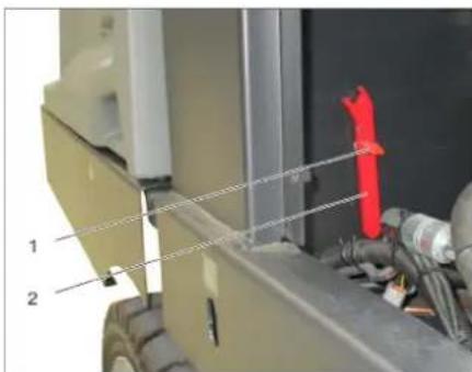
1 Hydraulic pump 2 Wrench 3 Tank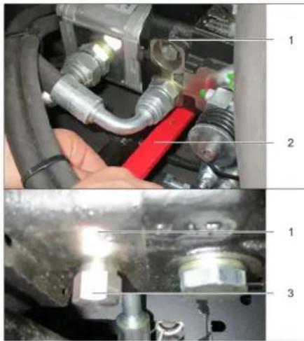
Loosen the lock with the wrench (open the free travel) until the device can be moved. → IMPORTANT: after moving, lock the lock again (close the free travel = driving position).
Before starting work
General instructions
→ Before operation, read the manufacturer's manual and follow the safety rules. Place the machine on a level surface. Pull out the ignition key. Engage the parking brake.
Inspection and maintenance work
Daily before starting work
→ Check the fuel tank level. Check the oil level in the engine. → Check the level of the expansion tank for radiator coolant. Check the rubber rollers and side brushes for wear and the presence of tangled threads. → Check the wheels for tangled threads. → Check the centrifugal separator and air filter, clean if necessary. Check the correct condition of all control elements. → Check the device for damage. → Clean the dust filter using the filter cleaning button.
Note: Description see in chapter "Care and Maintenance".
Danger of ignition!
→ It is allowed to use only the fuel specified in the operating manual. → Operation of the machine in closed rooms is not allowed. → Ensure ventilation and open flame is not present. → Make sure that fuel does not get on hot surfaces. Check the fuel level with the fuel tank indicator. Turn off the engine. Open the fuel tank cap. Pour in fuel → Wipe off spilled fuel and close the fuel tank cap.
Operation
Adjusting the seat position
1 Seat adjustment lever 2 Seat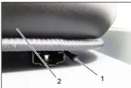
→ Pull the seat adjustment lever to the side. → Move the seat, release the lever and let it lock. → By moving the seat back/forward, check its locking.
Starting the device
Note: The device is equipped with a contact switch on the seat. When the seat is vacated, the device switches off.
1 Parking brake
2 Engine speed regulator
Take a seat on the operator's seat. Engage the parking brake. → Move the engine speed regulator forward by 1/3.
Preheating
Insert the key into the ignition lock. → Turn the ignition key to the "Preheating" position. The preheating lamp lights up.
Turn the ignition key to start the engine. After the preheating lamp goes out, turn the key to position II. After the device has started, release the ignition key.
Do not press the starter for more than 10 seconds. Before re-engaging the starter, wait at least 10 seconds.
Movement of the device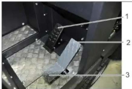
1 Brake pedal
2 Pedal "Forward" 3 Pedal "Reverse"
Fully depress the clutch pedal (working clutch). Press and hold the brake pedal. Release the parking brake.
Moving forward
Press the accelerator pedal smoothly.
Moving backward
DANGER
Danger of injury!
When moving in reverse, there should be no danger to people; if necessary, provide instructions. Press the accelerator pedal smoothly.
Nature of movement
With the accelerator pedal, it is possible to continuously adjust the speed of movement. Avoid sudden pressing of the pedal, as in this case the hydraulic system may be damaged. When driving over bumps, reduce the pressure on the accelerator pedal.
TopMoxeHne
→ When releasing the parking brake, the machine automatically brakes and stops.
Note: The brake action can be intensified by pressing the foot brake.
Overcoming obstacles
Overcoming fixed obstacles up to 70 mm high: → Obstacles should be overcome carefully, moving forward at a slow speed.
Overcoming fixed obstacles higher than 70 mm:
→ Such obstacles should only be overcome using the lifting frame.
Maintenance
CAUTION
Do not allow packaged items, wire, etc. to enter the machine, as this may damage the lifting mechanism.
Note: To achieve optimal performance, it is necessary to adjust the travel speed to the local conditions.
Note: During operation, the air filter should be cleaned regularly.
Note: When working in particularly dusty conditions, the air filter should be cleaned more often.
Control lever
1 Control lever for hydraulic side brushes 2 Control lever for waste container hopper
3. Cylinder lock control lever
4. Hopper cover control lever. Cylinder and side brush control lever.
→ Control lever (1) forward: cylinder brush engages, side brush engages and lowers. → Control lever (1) backward: cylinder brush disengages.
Debris hopper control lever
→ Debris hopper control lever (2) forward: debris hopper lowers. → Debris hopper control lever (2) backward: debris hopper raises.
Roller brush control lever
→ Cylinder brush control lever (3) forward: cylinder brush raises. → Cylinder brush control lever (3) backward: cylinder brush lowers.
Hopper cover control lever
Hopper cover control lever (4) forward: debris hopper cover opens. → Hopper cover control lever (4) backward: debris hopper cover closes.
Dry sweeping
Turn on the machine. → On flat surfaces: Control lever for cylinder and side brushes (1) backward: engage cylinder brush. Control lever for cylinder brush (3) backward: cylinder brush lowers. → Hopper cover control lever (4) forward: hopper cover opens. → On edges: Control lever for cylinder and side brushes (1) forward: cylinder brush engages, side brush engages and lowers. Control lever for cylinder brush (3) backward: cylinder brush lowers.
Sweeping wet or damp floors
Turn off the machine. → On flat surfaces: Control lever for cylinder and side brushes (1) backward: engage cylinder brush. Control lever for cylinder brush (3) backward: cylinder brush lowers. → Hopper cover control lever (4) forward: hopper cover opens. → On edges: Control lever for cylinder and side brushes (1) forward: cylinder brush engages, side brush engages and lowers. Control lever for cylinder brush (3) backward: cylinder brush lowers.
Empty the debris collection hopper
DANGER
Danger of tipping!
During removal of the contents from the waste collection hopper, people and animals must not be in the movement area of the hopper. Danger of tipping! During removal of the contents from the waste hopper, the machine must be on a level surface.
DANGER
Danger of crushing! Do not touch the movable mechanism of the emptying device of the reservoir. Do not put your hands under the hopper.
WARNING
Danger of injury and damage! During the emptying process, material may be ejected. Keep a sufficient distance.
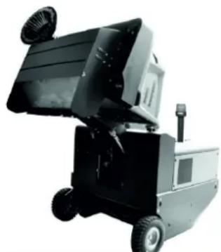
→ To open the hopper lid, move the hopper lid control lever (4) forward. → To close the hopper lid, move the hopper lid control lever (4) backward. → To raise the hopper lid, move the hopper control lever (2) backward. → Slowly drive up to the dust collection reservoir. Engage the parking brake. → To open the hopper lid, move the hopper lid control lever (4) forward. → To empty the waste hopper, move the waste hopper control lever (2) forward. → To close the hopper lid, move the hopper lid control lever (4) backward to the end position. Release the parking brake. Slowly drive away from the dust collection reservoir. → To empty the waste hopper into the end position, move the waste hopper control lever (2) forward.
Switching off the machine
→ To open the hopper lid, move the hopper lid control lever (1) to the center and the control lever (3) forward. → To close the hopper lid, move the control lever (4) backward. → Fully pull out the engine speed regulator. Press the brake pedal. Engage the parking brake. → Turn the ignition key to position "0" and remove it from the lock.
Transport
DANGER
Injury during transport!
→ Observe the machine's own weight (transport weight) when transporting on a trailer or truck. → When transporting the machine in transport vehicles, observe the applicable local government regulations aimed at preventing tipping. Turn the ignition key to position "0" and remove it from the lock. Engage the parking brake. → Secure the machine to stable attachment points (4x) using tension belts, ropes, or chains. Secure the machine by placing wedges under its wheels. → Before transporting, disconnect the battery terminals.
Storage / Taking out of operation
DANGER
Danger of injury! When storing, pay attention to the weight of the device.
→ Install the spreading machine on a level surface in a dry, frost-protected room. Cover it to protect against dust. → Lower the side supports so they are not damaged. Close the hopper lid. Turn the ignition key to position "0" and pull it out of the lock. Engage the parking brake. → Take measures against unauthorized use of the spreading machine.
If the spreading machine is not used for an extended period, the following must be observed additionally:
Change the engine oil. → Drain the coolant and check that there is enough antifreeze in the cooling system. Clean the spreading machine inside and out. Disconnect the battery cables. → The battery should be charged, and then recharged every two months.
Maintenance and service
General instructions
CAUTION
Danger of injury!
→ The dust filter does not need to be washed. → Repair work may only be carried out by authorized service centers and specialists in this field who are familiar with the relevant safety regulations. → Repaired devices must undergo a safety check in accordance with VDE 0701. → Place the spreading machine on a level surface. Turn the ignition key to position "0" and pull it out of the lock. Engage the parking brake.
Cleaning
CAUTION
Danger of damage!
→ It is not permitted to clean the device with a water hose or a high-pressure water jet (risk of short circuit and other damage).
Cleaning the device from the inside
Onachocmb noJyueHua mpaem!
Hocumb 3auumHyIO Macky npomue nblu u 3auumHbIe OQU. → PpoTepeTb annapaT prnkoi. O6dytb annapat cKaTbIM BO3dyxOM.
YncTka annapaTa chapyKu
OuHCTb annapaT, nCNoB3yA DnA 3TOBO BnaXHyIO Tprkky, npOnNTaHHyIO MRAKIM UeJeONyHbIM pACTBOPOM.
Yka3aHne: NcnoB3oBaHne arpeccnBbIX MOIOUIN CpeCDTB He DOnyckaetCra.
PepnoDnUHocTbTexHnueckoro 06cnyXnBaHn
Yka3aHHe: CyeTnK pa6OuNX yacOB coo6-uaeT O MOMeHTe npoBeHnRA 0cCnyXnBa-HNIA.
Texnueckoe 6cbnykBaHne, OcyuectBJIaEmoe KHeHTOM
Yka3aHHe: Bce pa6oTbI no TEXHnueckomy o6cIyKuBaHnIO CO cToPOHb KIneHTa DOJHXbI IPOBODITCBc KBaINOpCuPBOHaHbIM CNEUAnNCtOM. B cNYae Heo6XOnMocTN B IHO6OI MOMENT MOKHO O6paNTbC 3a NOMOuBIO CNEUAN3NpOBaHHyTO TropBOyO opraHn3aUΦnpMbI Karcher.
ExeHHeBHOeTexnueckoe 06cnyKbHaHne:
→ PpOBepntb 3aONHeHne TOnJIINBHO6aka. PpOBePntb ypoBeHb Macna B DnBraTe- ne. → PpOBepuMb ypoBeHb HAnOpHeHnKOMneHcaUOnHHoro 6aKa paDnAtopa XndKOCTHOO OxJaXKeHn. → PpOBepntb MeTyuIN BaJIHK N 6OKOBbie UeTKN Ha I3HOC IN HAIuHne HAmOTaB- WIXCJ JeHT. PPOBepuTb TOnJIINBHyI QnIbTp. → PpOBepntb ueHTpoBExKhbl cenapaTOp n BO3dyHbI ΦnIbTp, npn Heo6xoDn-MOCTN OCHNTb. PpOBepuNb uCnpaBHOe COCTOHNBEcx 3JemeHToB ynpabJeHnA. → PpOBepuTb np6op Ha npEMeT noBpeKdHn.
ExeHeIbHoeTexnueckoe 06cnyKuBaHne:
OuHCTb BOJHOH paHaTOp. OuHCTnTb rnpabNueckm MacnHbIpaHaTOp. → PpOBepntb rnpabnueckyU yCTaHOB-ky. PPOBepntb ypoBeHb Macla B rnpabNueeCKO CNCTeme, → PpoBepuTb ypoBeHb TOPMO3HOJ XnID-KoCTN.
→Пюверпь ИЗСОуПОТнITeNBbIX HAKПадOK,пИН HeOБхОДМОCTN 3amEHNITb →Поверпьисma3аькрblkype3epByapa.
Texnueckoe 06cnykBaHne KaKdble 50 yacob pa6oTbI:
→ Engine oil (diesel engine)
Maintenance of wearing parts:
Replace worn seals. Adjust or replace valve clearances. Replace damaged shafts. Replace side brushes.
Note: See description in chapter "Maintenance Work".
Maintenance performed by customer service
Note: To maintain the warranty, all maintenance and repair work during the warranty period must be carried out by an authorized Karcher customer service in accordance with the maintenance booklet.
Maintenance after 50 operating hours:
→ Perform the first maintenance in accordance with the maintenance schedule of the customer service.
Maintenance after 250/500/1000/1500/2000 operating hours:
→ Perform maintenance in accordance with the maintenance schedule of the customer service.
Maintenance work
Preparation:
→ Place the sweeping machine on a level surface. → Turn the ignition key to position "O" and remove it. Secure the parking brake.
General safety information
DANGER
Danger! Injury hazard!
Always install protective shields when working under the reservoir for waste collection. Work may only be performed outside the danger zone.
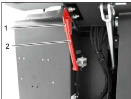
1 Protective shield
2 Protective shield
Fold up the protective shield over the reservoir and insert it into the holder (protective shield).

Please do not allow motor oil, diesel fuel, heating oil, or gasoline to enter the environment. Please collect used oil and dispose of it properly, without harming the environment.
Safety instructions for handling accumulators
When handling accumulators, the following safety instructions must be observed:
Installation of accumulators DANGER
Danger of injury!
Always install protective shields when working under the reservoir for waste collection. Work may only be performed outside the danger zone. → Fold up the protective shield over the reservoir and insert it into the holder (protective shield).
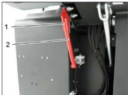
1 Protective shield 2 Protective shield
Open the side panel as described in the chapter 'Replacing the filter element' above. Loosen the six bolts on the side locking plate. Loosen the screw (SW13) on the front locking plate. Press the side seal down (long hole) until its edge is at a distance of 1-3 mm from the floor. → Tighten the locking plate. → Repeat the sequence for the other side.
Clean the dust filter manually
→ Switch on the manual filter cleaning, check/replace the dust filter
The machine has been received!
When working with the filter unit, wear a dust mask. Follow the safety instructions for handling fine dust. → Clean the dust filter using the filter cleaning tool. Empty the container for collecting debris.
1 Locking the device cover
2 Device cover 3 Filter cover Open the lock. To do this, turn the screw with a star-shaped head. Fold the device cover forward.
1 Lock, filter cover (2x) 2 Filter cover Open the lock. → Open the filter cover.
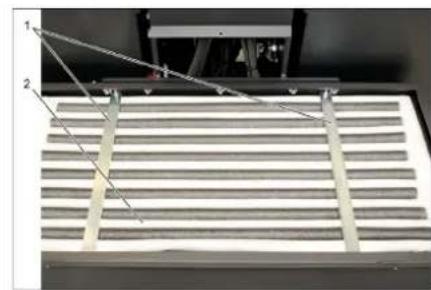
1 Replaceable filters 2 Dust filter → Check the dust filter, if necessary clean or replace it.
Note
Replacing the dust filter may only be carried out by Karcher service staff. Secure the filter cover.
Checking and adjusting the V-belt
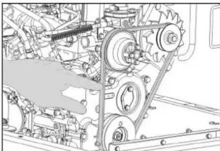
The V-belt at a pressure of 10 kg should sag approx. 7-9 mm. → The V-belt tension is set by trained service personnel.
Checking and replacing the air filter
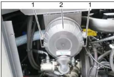
1 Cover 2 Air filter housing
→ Remove the side panel. → Remove the air filter housing. Replace the air filter cartridge.
Note: Installation position - the ventilation opening points downward (see figure).
Centrifuge separator cleaning
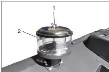
1 Drum sieve
2 Centrifuge separator
Remove the drum sieve on the centrifuge separator. Clean the centrifuge separator.
Replacing the fuses
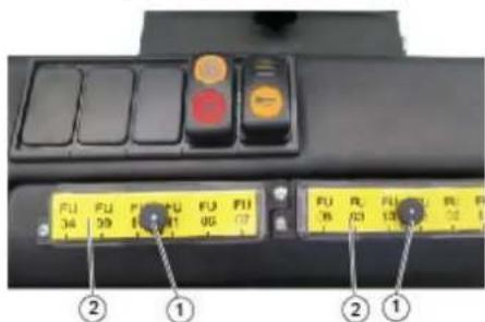
1 Cap with knurled nut 2 Fuse box cover Unscrew the cap with the knurled nut. Open the cover on the fuse box. Check the fuses. Replace defective fuses.
Note: Use only fuses with the same rating.
Note: The fuse FU 01 is located in the control cabinet.
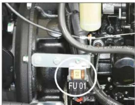
Chairman of the Board of Management
S. Reiser
Director Regulatory Affairs & Certification
Authorized employee for document management:
S. Reiser
www.kaercher.com/REACH
Warranty
Chairman of the Board of Management
Director Regulatory Affairs & Certification
71364 Winnenden (Germany)
Tel.: +49 7195 14-0
Fax: +49 7195 14-2212
Winnenden, 2020/01/01
www.kaercher.com/REACH
Warranty
Symbol of glow plug: Preheating
2006/42/EC (+2009/127/EC)
2014/30/EU
2000/14/EC
Harmonized standards used
EN 60335-1
EN 60335-2-72
EN 55012: 2007 + A1: 2009
EN 61000-6-2: 2005
EN 62233: 2008
Conformity assessment procedure used:
2000/14/EC: Annex V
Chairman of the Board of Management
Director Regulatory Affairs & Certification
Authorized person for compiling the technical documentation:
S. Reiser
Alfred Karcher SE & Co. KG
71364 Winnenden (Germany)
Tel.: +49 7195 14-0
Fax: +49 7195 14-2212
Winnenden, 2020/01/01
General instructions. SL 1
Environmental protection .SL1
Warranty .SL 1
Accessories and spare parts SL 1
Symbols in the operating instructions SL 1
Symbols on the device . . . . SL 1
Intended use..SL 2
www.kaercher.com/REACH
Warranty
Relevant EU directives:
2006/42/EC (+2009/127/EC)
2014/30/EU
2000/14/EC
Chairman of the Board of Management
S. Reiser Director Regulatory Affairs & Certification
Authorized person for documentation:
S. Reiser
Alfred Kärcher SE & Co. KG
71364 Winnenden (Germany)
Tel.: +49 7195 14-0
Fax: +49 7195 14-2212
Winnenden, 2020/01/01
www.kaercher.com/REACH
Warranty
2006/42/EC (+2009/127/EC)
2014/30/EU
2000/14/EC
Chairman of the Board of Management
S. Reiser Director Regulatory Affairs & Certification
Documentation administrator:
S. Reiser
Alfred Kärcher SE & Co. KG
71364 Winnenden (Germany)
Tel.: +49 7195 14-0
Fax: +49 7195 14-2212
Winnenden, 2020/01/01
Weight in empty state (transport weight) 880 kg*
EU Directives complied with:
2006/42/EC (+2009/127/EC)
2014/30/EU
2000/14/EC
Harmonized standards used:
EN 60335-1
EN 60335-2-72
EN 55012: 2007 + A1: 2009
EN 61000-6-2: 2005
EN 62233: 2008
Chairman of the Board of Management
Director Regulatory Affairs & Certification
71364 Winnenden (Germany)
Tel.: +49 7195 14-0
Fax: +49 7195 14-2212
Winnenden, 2020/01/01
General Instructions SK1
Control panel. SK 4
Pedal SK 4
Indicator lamps and display SK 4
Before commissioning. SK 5
2006/42/EC (+2009/127/EC)
2014/30/EU
2000/14/EC
Applied harmonized standards:
EN 60335-1
EN 60335-2-72
EN 55012: 2007 + A1: 2009
EN 61000-6-2: 2005
EN 62233: 2008
Applied conformity assessment procedures:
2000/14/EC: Annex V
Chairman of the Board of Management
71364 Winnenden (Germany)
Tel.: +49 7195 14-0
Fax: +49 7195 14-2212
Winnenden, 2020/01/01
Warranty HR 1
www.kaercher.com/REACH
Warranty
In every country, the warranty conditions issued by our responsible distribution organization apply. We will repair any faults on the machine free of charge during the warranty period, provided that the cause is a material or manufacturing defect. In the event of a warranty claim, please contact your dealer or the nearest authorized service center, presenting the proof of purchase.
2006/42/EZ (+2009/127/EZ)
2014/30/EU
2000/14/EZ
Applied harmonized standards:
EN 60335-1
EN 60335-2-72
EN 55012: 2007 + A1: 2009
EN 61000-6-2: 2005
EN 62233:2008
H.Jenner Chairman of the Board of Management
S. Reiser Director Regulatory Affairs & Certification
71364 Winnenden (Germany)
Tel.: +49 7195 14-0
Fax: +49 7195 14-2212
Winnenden, 2020/01/01
General notes. SR 1
Environmental protection. SR 1
Warranty. SR 1
Accessories and spare parts. SR 1
Symbols in the operating instructions SR 1
Symbols on the device. SR 1
Intended use SR 2
Foreseeable misuse SR 2
www.kaercher.com/REACH
Warranty
In every country, the warranty conditions issued by our responsible distribution organization apply. We will rectify any faults on the device free of charge during the warranty period, provided that the cause is a material or manufacturing defect. In the event of a warranty claim, please contact your dealer or the nearest authorized service center with your proof of purchase.
Accessories and spare parts
DANGER
To prevent hazards, repairs and installation of spare parts may only be carried out by authorized service personnel.
Only use accessories and spare parts approved by the manufacturer. Original accessories and original spare parts guarantee that the device can operate safely and without interference.
You will receive additional information about spare parts at www.kaercher.com in the Service section.
Symbols in the operating instructions
DANGER
Indicates an imminent threat of danger that leads to serious bodily injury or death.
WARNING
Indicates a potentially dangerous situation that could lead to serious bodily injury or death.
CAUTION
Indicates a potentially dangerous situation that could lead to minor bodily injury or cause material damage.
ATTENTION
Note that indicates a potentially dangerous situation that could cause material damage.
Symbols on the device
| Opasnost od opekotina na vrelim površinamal! Pre obavljanja radova na urežaju treba sačekati da se izduvni sklop dovoljno ohladi. | |
| Radove na urežaju uvek obavlajte noseci odgovarajuće rukavice. | |
| Opasnost od prignječenja uvlačenjem meduPokretne delove vozila | |
| Opasnost od povredaPokretnim delovima. Zabranjeno zahvatanje rukama. | |
| Opasnost od požara. Ne usisavajte zapljene ili uzarene predmete. | |
| Prihvatnik lanca i mesto oslananja krana | |
| Prihvatna mesta za autodizalicu | |
| Maksimalan nagib podloge prilikom vožnji s izdignutom posudom za prljavstinu. | |
| Dopušteno je savladavati samo uspone do 18% u smeru vožnje. | |
| Opasnost od oštećenja! Filter za prăsinu ne sme da se pere u vodi. |
Name of the manufacturer
2006/42/EC (+2009/127/EC)
2014/30/EU
2000/14/EC
Harmonized standards applied:
EN 60335-1
EN 60335-2-72
EN 55012: 2007 + A1: 2009
EN 61000-6-2: 2005
EN 62233: 2008
Chairman of the Board of Management
S. Reiser
Director Regulatory Affairs & Certification
71364 Winnenden (Germany)
Tel.: +49 7195 14-0
Fax: +49 7195 14-2212
Winnenden, 2020/01/01
General safety instructions. Designated use. Spare parts. Symbols used. Symbols on the device.
Intended use. Improper use. . Required personnel qualifications.
Safety instructions... Safety instructions for maintenance... Safety instructions for operation... Devices with internal combustion engine... Devices with high pressure... Devices with water protection cover... Safety instructions for transport of the device... Safety instructions for maintenance and technical service...
Function.
Instructions for unpacking.
Maintenance. Functional elements. Device overview. Maintenance.
Repairs.
Control lamps. LEDs.
Before starting operation. Locking/unlocking the locking mechanism. .
Starting the device without its own starting device.
Starting operation. General instructions. Checking the tightness. Filling.
Operation. Setting the water quantity. Starting the device. Stopping the device. Operation. Emptying the reserve water tank. Switching off the device.
Transport.
Storage/Disposal .BG7
Maintenance BG7 General instructions BG7 Maintenance intervals BG7 Maintenance activities BG
Troubleshooting..BG 14 Technical data BG 15 EC Declaration of Conformity BG 16
Before first use of your device, read through the original operating instructions and follow them. Keep them for
better use and for future reference.
General instructions
If transport damage is detected during unpacking, notify the dealer from whom you purchased the product.
The instructions in the operating manual must be followed, as well as the general safety and accident prevention regulations.
Environmental protection

Packaging materials can be recycled. Do not dispose of packaging with household waste, but hand it over to secondary raw materials for reuse.

Old devices contain recyclable materials that can be reused. Therefore, dispose of old devices through appropriate collection systems.
Motor oil, diesel fuel, and gasoline must not enter the environment. Dispose of used oils and fuels in an environmentally friendly manner.
Instructions on components (REACH)
Current information on components can be found at:
www.kaercher.com/REACH
Tapaanu
The warranty conditions issued by our authorized distributor apply. Damage to your device will be repaired free of charge within the warranty period, provided it is due to defects in materials or manufacturing. In the event of a warranty claim, please contact your distributor or the nearest authorized service center, presenting the proof of purchase.
Spare parts
DANGER
To avoid hazards, repairs and replacement of spare parts must only be carried out by authorized service personnel.
Only use accessories and spare parts approved by the manufacturer. Original accessories and original spare parts guarantee safe and trouble-free operation of the device.
Further information on spare parts can be found at www.kaercher.com in the service section.
Symbols on the device
DANGER
Warning of immediate danger that can lead to serious injuries or death.
WARNING
Warning of a potentially dangerous situation that could lead to serious injuries or death.
CAUTION
Indication of a potentially dangerous situation that could lead to minor injuries or damage to property.
Warning about possible dangerous situation that may lead to material damage.
Warning symbol
Safety instructions
Safety instructions for maintenance
→ (See chapter on safety) If the device is equipped with a PVC hose, it must not be used at low ambient temperatures (below 0°C). For any questions regarding your device, please contact Karcher. → The device must be checked for perfect condition and operational safety before use. If the device is not in perfect condition, its use is prohibited. → The safety instructions must be observed when working with the device in hazardous areas (e.g., petrol stations). Work in potentially explosive areas is prohibited.
DANGER
Danger of injury!
Do not use the device without protective covers against falling objects in areas where there is a risk of falling objects for operating personnel. → The operator must use the device according to the instructions. During work, the device must be kept at a safe distance from surrounding objects and attention must be paid to third parties, especially children. The basic safety measures, rules, and regulations applicable to motor vehicles must be observed. → Before starting work, the operator must ensure that all protective devices are correctly installed and functioning. → The operator of the device is responsible for accidents involving other persons or their property. → The operator must wear appropriate protective clothing. Wear sturdy shoes and avoid loose clothing. → Check the device before starting work (e.g., for damage). Ensure good visibility! → The device must never be left unattended while the motor is running. The operator can
start the device only when the motor is switched off, the device is secured against unintentional movement, and the key is removed.
To avoid improper use of the device, the key must be removed. → The device may only be used by persons who have been trained in its operation and have demonstrated their ability to work with it, and who have been explicitly instructed in its use. This device is not intended to be used by persons (including children) with reduced physical, sensory, or mental capabilities, or lack of experience and/or knowledge, unless they are under the supervision of a person responsible for their safety or have received instructions on how to use the device. → Children must be supervised to ensure they do not play with the device.
CAUTION
Danger of injury! Do not touch the nozzle, hose, or other parts, as they may become hot during operation.
Safety instructions for driving
DANGER
DANGER! Check the load capacity on the basis before proceeding further.
DANGER
Danger of tipping, danger of falling!
→ The speed of movement must be adapted to the relevant conditions. Danger of overturning on hard slopes. → Travel only on slopes up to 18% in the direction of travel. Danger of overturning on unstable ground. → Ensure that you are always on a stable base.
Danger of overturning on hard, sloping ground.
→ The direction of travel must only be on slopes up to a maximum of 10%.
Devices with internal combustion engine
Do not use the machine at altitudes above 1200 m.
Danger
Danger of falling!
→ The gas cylinder compartment must not be closed. Do not lean on the exhaust gas outlet and do not touch it with your hand (danger of burns). → Do not touch or smell the engine (danger of burns).
Exhaust gases are toxic and harmful to health; they must not be inhaled. → The engine continues to run for approx. 3-4 seconds after switching off. During this period, do not touch the hot engine parts.
Devices with high lift
DANGER
Danger of falling!
Perform work on the high-pressure nozzle only after the nozzle has been removed and the device has been switched off. Remove the safety device from the danger zone only after it has been switched off.
Device with protective cover for water
INSTRUCTIONS
The protective cover for water (optional) provides protection against coarse dirt and parts. The device does not provide protection against water jets!
Check the protective cover for damage daily. If the protective cover or individual parts of it are damaged, the protective cover must be replaced. It is not permitted to repair or modify the protective cover, nor to install parts, components, or modules not approved by Kärcher, and this may limit the function of the protective cover under certain circumstances.
Safety instructions for transporting the device
Take into account the weight of the device (without accessories) when transporting it with a trailer or vehicle. For transporting the device, remove the battery and secure the device securely.
Safety instructions for maintenance and servicing
Before cleaning and servicing the device, switch off the device and remove the battery. When working on electrical equipment, the battery must be disconnected.
For the battery, first disconnect the negative pole, then the positive pole. When reconnecting, reverse the order. First connect the positive pole, then the negative pole. Do not clean the device with a hose or high-pressure water jet (risk of short circuit or other damage).
Repairs must only be carried out by authorized service or by specialists in this field who are familiar with all relevant safety regulations. The device must be checked for safety and proper functioning in accordance with the relevant regulations after any repair. Perform work on the device only with the battery removed.
Function
The washing machine works by means of the washing nozzles.
The washing nozzles are adjusted to the height of the water reservoir for the washing process. The washing process cleans the nozzles and the surfaces to be washed. The dirt is sucked through the dirt filter with the help of the suction nozzle.
Disposal instructions
WARNING: Before operating and adjusting!
→ When operating, keep the device in mind! Do not use sharp objects, as the device may be damaged.
| Tero no 63 tobap (Tero no prn TpaHcnpor) | 880 kg* |
| * Ako ca MOHTIpaHn npNCtABKn, TeroIto e oOe NO-BVCOKO. | |
→ When operating the device, use the frame or crane! → When using the frame, pay attention: Free space of at least 70 mm. If the device is delivered on a pallet, the lowering frame is included as an accessory.
The instructions are on page 2 (inside cover of the box).
Important note: The device must be properly secured with 2 screws.
A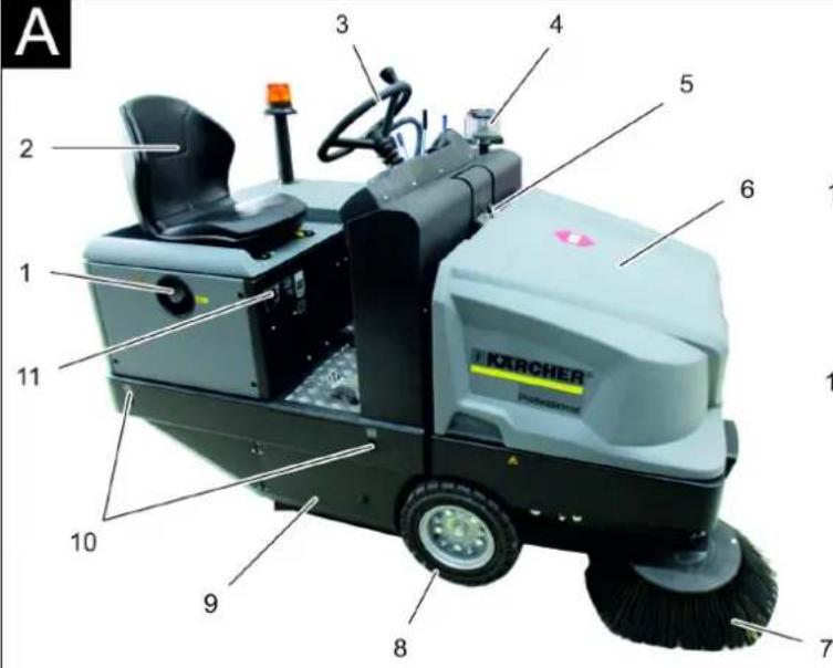
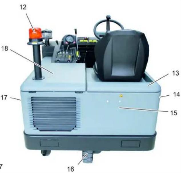
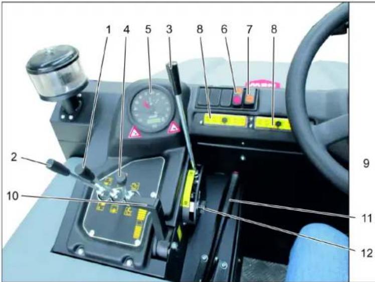
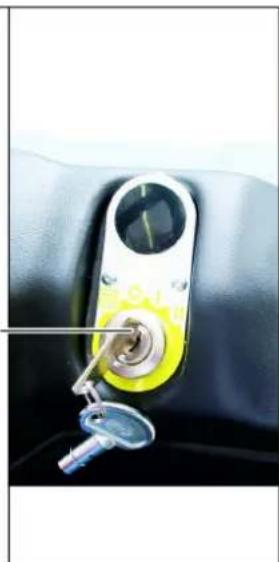
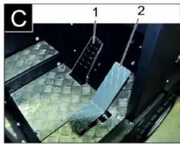
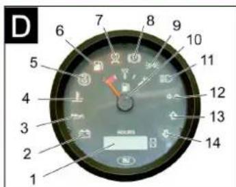
Machine image for adjustment
Figure A
1. Cap for filling 2. Seat (with contact for seat heating) 3. Water 4. Centrifugal pump 5. Blocking of the device channel 6. Device channel 7. Drain hose, separate 8. Pre-knee 9. Post 10. Adjustment foot for fixing 11. Body tube 12. Drain hose for the outlet 13. Device channel outlet 14. Cover, separate 15. Covering of the occupied part 16. Rear knee 17. Cover, right 18. Outlet channel (drain hose)
Service area
Figure
1. Adjustment of the drain hose
Drain hose and drain hose
Post adjustment: Drain hose connection, etc.
TABLE OF CONTENTS
1. Introduction: Metal balancer.
2. Maintenance of the reservoir for the changed
Reservoir for the changed lifting/
LOWERING
3. Control of the metal balancer
JACK
Lifting and lowering of the metal
BAR
4. Maintenance of the hook of the reservoir
Opening/closing of the hook of the
reservoir
5. Control of the lamp and the fuse
6. Request for the ventilator and cleaning of the filter
Control of the surface and the thickness
Before starting operation
→ Check the fuel level in the fuel tank. → Check the engine oil level. Check the oil level and top up if necessary. → The air filter must be checked for dirt and damage. Check the filter element and replace if necessary. → Check the centrifugal clutch and the drive belt; if necessary, replace them. → Check the function of all service elements. Check for wear and tear. → Replace the air filter with a new one for filter maintenance.
Note: The description is given in the operating instructions.
Refueling
DANGER
Danger of explosion!
→ It is forbidden to use the machine without following the operating instructions. → Do not refuel in enclosed spaces. Smoking and open flames are prohibited. → Avoid fuel spillage on hot surfaces. Check the fuel tank cap for tightness. → Turn off the engine. Open the fuel tank cap. Refuel with diesel fuel. → Wipe up any spilled fuel and close the fuel tank cap.
Operation
Adjusting the water nozzle
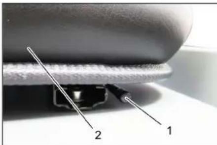
1. Loosen the nozzle. 2. Water nozzle → Pull out the nozzle for adjustment. → Move the nozzle and fix it in position. → Check by moving forward and backward that the nozzle is adjusted.
Starting the device
Note: The device is equipped with a contact switch and a water nozzle interlock. When the water nozzle is released, the device switches off.
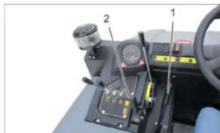
1. Locking lever 2. Engine speed control lever on the water nozzle. The locking lever must be locked. → Move the speed control lever on the handlebars 1/3 forward.
Preheating
→ Insert the key into the ignition lock. Turn the key to the "Preheating" position. The preheating indicator lamp lights up.
Starting the engine
To start the engine, press the brake pedal. → The preheater lamp lights up. Turn the key to the "start" position. → When the engine starts, release the key.
Note: Never operate the starter for more than 10 seconds. If the engine does not start after 10 seconds, wait before trying again.
Driving the vehicle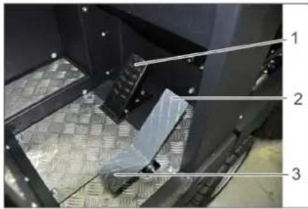
1. Press the clutch pedal. 2. Select forward or reverse gear. → Adjust the engine speed with the throttle (working lever). → Press the brake pedal and release the clutch. Release the parking brake.
Driving forward
Press the "forward" pedal for movement.
Driving forward
DANGER
Danger of crushing! → When driving in reverse, there is a risk to people. If necessary, have someone give you directions. → Press the "reverse" pedal for movement.
Behavior when driving
→ The travel speed during driving can be adjusted steplessly. → Always operate the pedals carefully, as the steering may be abrupt. → When applying full power, the travel pedal may be difficult to press.
Brakes
→ When the travel pedal is released, the vehicle brakes automatically and comes to a stop.
Note: The brake can be applied by pressing the brake pedal.
Adjusting the obstacles
Adjusting above the stand in place of obstacles up to 70 mm:
→ Set it carefully in the direction of the arrow. Adjusting above the stand in place of obstacles over 70 mm: Can be adjusted above the obstacles only with the help of a suitable ramp.
Mowing mode
WARNING
Do not change the settings for the blades, knives or similar, as this may lead to damage to the mower mechanism.
Note: To achieve optimal results when mowing, the speed of the mower must be adjusted to the conditions.
Note: The grass catcher bag must be emptied regularly.
Note: When working in areas with grass, the mower must be set lower.
Maintenance positions
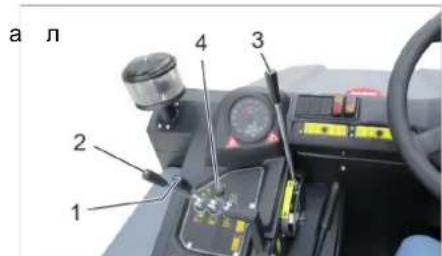
1. Maintenance position for the cutting deck 2. Maintenance position for the grass catcher tank 3. Maintenance position for the cutting deck 4. Maintenance position for the grass catcher tank
Maintenance position for the cutting deck
Maintenance position (1) Forward: Cutting deck up, lowering and lifting the cutting deck. Maintenance position (1) Back: Cutting deck up.
Maintenance position for the grass catcher tank
→ Maintenance position for the grass catcher tank (2) Forward: The grass catcher tank is lowered. → Maintenance position for the grass catcher tank (2) Back: The grass catcher tank is raised.
After controlled lowering of the metal roller (3): the metal roller is lowered. After control of the metal roller (3) back: the metal roller is raised.
After servicing the reserve tank valve
After servicing the reserve tank valve (4) forward: the reserve tank valve opens for changing the water. After servicing the reserve tank valve (4) back: the reserve tank valve closes for changing the water.
Removing dry floors
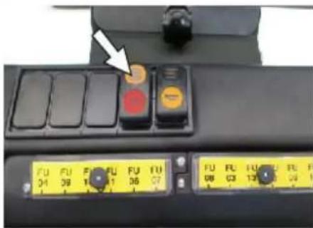
Turn on the ventilator. → For cleaning the surfaces: After controlled lowering of the metal roller and the side brush (1) forward: the metal roller is on. After controlled lowering of the metal roller (3) forward: the metal roller is lowered. → After servicing the reserve tank valve (4) forward: the reserve tank valve opens. → For cleaning the side brushes:
After control of the metal roller and the side brush (1) forward: the metal roller is on, the side brush is on and lowered.
After control of the metal roller (3) back: the metal roller is raised.
Removing wet and damp floors
→ Turn off the ventilator. → For cleaning the surfaces: After control of the metal roller and the side brush (1) back: the metal roller is off.
After control of the metal roller (3) back: the metal roller is raised.
→ After servicing the reserve tank valve (4) forward: the reserve tank valve opens. → For cleaning the side brushes:
After control of the metal roller and the side brush (1) forward: the metal roller is on, the side brush is on and lowered.
After control of the metal roller (3) back: the metal roller is raised.
To drain the reserve tank for changing the water.
DANGER!
Danger of injury!
Danger of injury!
Danger of injury!
Danger of injury!
Never reach into the moving mechanism. Do not force the belt grinder.
CAUTION
Danger of injury and damage!
Material may be ejected from the rotating belt during the grinding process. Keep sufficient distance.
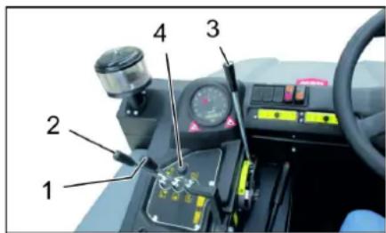
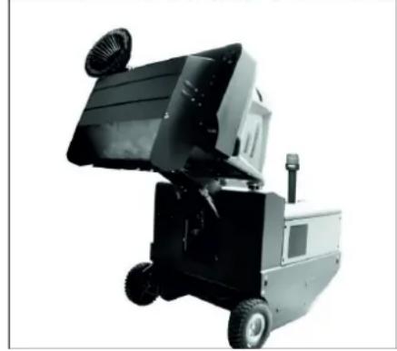
→ Move the belt grinder to the working position: working position 1 in the middle, working position 3 forward. Close the reservoir valve, so that the service position (4) is at the rear. → Move the reservoir valve for the removed material, so that the service position of the reservoir for the removed material (2) is at the rear. → Empty the collection reservoirs. → Block the locking slide. → Open the reservoir valve, so that the service position of the reservoir valve (4) is forward and empty the reservoir for the removed material.
Close the reservoir valve, so that the service position of the reservoir valve (4) is at the rear, until it tilts to the extreme position. Release the locking slide. Empty the collection reservoirs. Lower the reservoir for the removed material to the extreme position, so that the service position of the reservoir for the removed material (2) is at the rear.
Switch off the device
→ Move the belt grinder to the working position: working position 1 in the middle, working position 3 forward. Close the reservoir valve, so that the service position (4) is at the rear. → Turn the motor switch to the off position. → Press the locking slide and hold it pressed. → Block the locking slide. Turn the key to "0" and remove the key.
Transport chains!
Take into account the weight of the device without goods (empty during transport) on the axle during transport with a trailer or self-propelled. → When transporting by car, secure the device according to the relevant directives for loading and unloading. → Turn the key switch to "0" and remove the key. → Lock the parking brake. Secure the device at the fixing points (4x) with tension belts, chains, or ropes. → The device must be secured with wheel chocks. → For transport on a machine, observe the instructions for the battery.
Storage/Shutdown
Danger of tipping and injury! When storing, keep the weight of the device in mind.
→ Place the machine on a level surface in a dry, frost-protected environment. Protect from dust with a covering material. → Lift the metal parts of the machine so that the brushes are not damaged. Close the tank cap. Turn the key switch to "0" and remove the key.
→ Lock the parking brake. → The machine must be secured against unintentional movement.
If the machine is to be out of use for a longer period, additionally observe the following:
→ Change the engine oil. → When expecting frost, drain the cooling water and check that there is sufficient antifreeze. → Clean the machine from the inside. → Disconnect the battery. → Charge the battery and recharge it every 2 months.
Maintenance
General information
Danger of injury! Do not clean the dust filter. → Repairs must be carried out only by authorized service or by specialists in this field who are familiar with all safety regulations. → Replacement of parts on the device is subject to safety inspection according to VDE 0701. → Place the machine on a level surface. → Turn the key switch to "0" and remove the key. → Lock the parking brake.
__SUPPIMER__
Maintenance intervals
Note: The hours of operation determine the maintenance intervals.
Maintenance work
Note: All service and maintenance work on the device must be carried out by a qualified specialist. If necessary,
a Karcher specialist can be called at any time.
Daily maintenance:
→ Check the fuel level in the fuel tank. → Check the engine oil level. → Check the coolant level in the expansion tank for antifreeze. → Check the metal strainer for leaks and damage. → Check the fuel filter. → Check the centrifugal air filter, clean if necessary. → Check the function of all service elements. Check the belts for wear.
Weekly maintenance:
→ Clean the water cooler. → Clean the hydraulic oil cooler. Check the hydraulic system. → Check the hydraulic oil level. → Check the coolant level. → Check the sealing parts for wear, replace if necessary. → Check the hose connections and the reservoir.
Maintenance every 50 operating hours.
→ Drain the water from the diesel water separator.
Maintenance according to wear:
→ Replace the sealing parts. Adjust the sealing strips or replace them.
→ CmHa Ha MeTuaBnBaJnK. →CMraHa Ha CtpaHnHHTe MeTNI.
Yka3aHHe: OINcAHHeTO BIXTe B rIJaBa DeiHOCTn no NOIDpBxKkata.
Ioppbjka ot ctpaHa Ha cepBn3HOTO 06cnykbahe Ha KIneHTN
Yka3aHHe: 3a da ce 3ana3r rapaHTnHnTe IpeTeHnI, NO Bpeme Ha nepnoDa Ha rapaHnra BCnKn CepBn3n H N OndbpxaUu DeHocTn Tpa6Ba Da ce n3BbPWBat OT OToPi3npaH cepBn3 Ha Karcher cbrnaCHO KNKKkata 3a TEXnuecko o6cnyKahe.
Poaepbka cne5 50 pa6oTHn yaca:
→ AnraknpaIte cepBn3a c nbpba noId-pbXka Ha ypeDa cbrnaCHO Yeknicta 3a uHcneKUIN.
Ioppbkca cJe2 250/500/1000/1500/ 2000 pa6oTHn yaca:
→ AnraKpaIte cepBn3a c NoIpbXka HaypeJa CbIpaCHO YeKInCTa 3a INHcneKuIN.
DneHoctn no noOpdpKkata
IoproTOBka:
→MetaHaTamaHnHaCeNoCTaBbPxy paBHnIOCKOCT. → KIIOU 3aIaIbAHe Da Ce 3aBbPtn Ha "0" I Da Ce IN3BaIIN KIIIOu. → Da ce 6noknpa 3actonopraBaata cnpaqka.
067u kazanna 3a cnpypnoct
ONACHOCT
Onachocm om HapaHaahe!
→ BuHaZu nocMaerIme npedn3Hama uHaHa npu noBouHam pe3epoap 3a u3MemeHOMO. → U38bpuweaume o6e3oanacraeaHemoHa onachama 30ha camo om6bH.
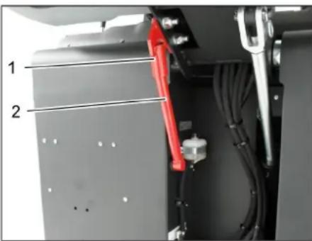
1. Insert the battery. 2. Insert the battery.
Close the battery compartment until it clicks into place.

Do not allow motor oil, fuel, or gasoline to enter the battery compartment. If you are not using the device, remove the batteries to protect the battery compartment.
Battery safety instructions
When working with batteries, always follow the safety instructions below:

Follow all instructions for the battery, including the user manual and operating instructions for the vehicle!

Wear protective goggles!

Keep children away from acid and batteries!

Explosion hazard!

No fire, sparks, open flames, or smoking!

Risk of burns!

Seek help!

Instruction manual!

Recycle!
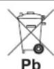
Do not dispose of batteries in the trash!
DANGER
Danger of explosion!
→ Do not charge batteries with uncovered poles. If the cover is lost, replace it.
DANGER
Danger of explosion!
Do not place tools on the batteries. Short circuit and danger of explosion.
DANGER
Danger of injury!
Never allow the arms to touch the poles. Always wear protective gloves when working on batteries.
DANGER
Danger of fire and explosion!
Smoking and open flames are prohibited. → Batteries that are being charged must be well ventilated, as highly explosive gases are produced during charging.
DANGER
Danger of burns!
→ Battery acid can cause burns on the skin. Rinse with clean water. → After that, consult a doctor immediately. → Contaminated clothing must be washed with water.
The equipment is a series of accumulators that do not require maintenance.
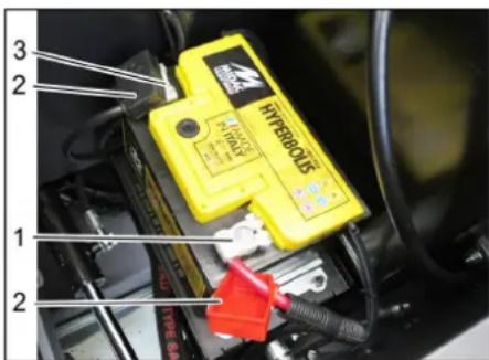
1 Positive terminal 2 Cover 3 Negative terminal
→ Place the accumulator in the compartment for the accumulator. → Make sure the base of the accumulator is held firmly. → Connect the positive cable (red cable) to the positive terminal (+). → Connect the negative cable to the negative terminal (-). → Install the cover.
→ Check the accumulator and the terminals to ensure they are sufficiently protected with protective grease.
Check the acid level of the accumulator and correct it (only for accumulators that require a small adjustment with the cap of the cells).
DANGER
Danger of burns!
→ Before filling the accumulator with acid, regularly check the acid level. Remove all caps of the cells. Take a sample from each cell with a hydrometer. - The acid of a fully charged accumulator at 20°C has a specific gravity of 1.28 kg/l. - The acid of a partially charged accumulator has a specific gravity between 1.00 and 1.28 kg/l. - In each cell, the specific gravity of the acid must be the same. The acid sample must be returned to the same cell. → Acid level of the cells: Fill the cells with distilled water up to the marking. Charge the accumulator. Replace the caps on the cells.
Charge the accumulator
DANGER
Danger of explosion!
→ Follow the safety instructions when handling accumulators. Follow the instructions for use of the charging device manufacturer.
DANGER
Danger of burns! → The accumulator must be charged with a suitable charging device.
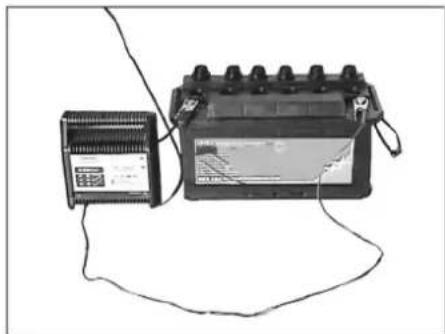
Connect the cable to the battery terminal. (Only for batteries with low self-discharge) Connect the positive cable of the charging device to the positive terminal of the battery. Connect the negative cable of the charging device to the negative terminal of the battery.
Set the charging current switch and turn on the charging device. Charge the battery with the lowest possible charging current. When the batteries are charged, the charging device switches off automatically. Then disconnect from the battery. (Only for batteries with low self-discharge)
Removal of the battery
Disconnect the terminal clamp from the negative terminal (-). Disconnect the terminal clamp from the positive terminal (+). Release the battery hold-down. Remove the battery from the battery tray. Dispose of the used battery in accordance with the applicable regulations.
Check the level of the brake fluid. Brake fluid level danger
Danger of burns!
The device becomes hot during operation. Allow the danger zone to cool down before touching it.
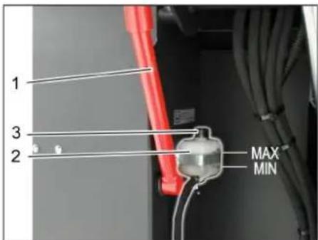
1 Filler neck
2 Reservoir for brake fluid 3 Cap. Slide the reservoir for brake fluid upward to the stop and secure it with the cap. For this question, see chapter "Adjusting the brake fluid reservoir". Check that the brake fluid reservoir has sufficient brake fluid.
Note
The fluid level must be between the Min. and Max. markings.
If necessary, add brake fluid. You can purchase it from the dealer.
Check the engine oil level and add oil
DANGER
Danger of burns! The engine may be hot. Allow it to cool down. Check the engine oil level at the earliest 5 minutes after switching off the engine.
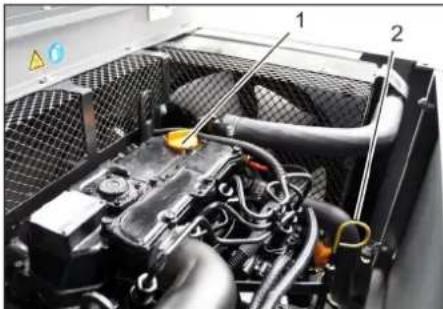
1. Oil dipstick (for checking oil level)
2. Checking the oil level. → Pull out the oil dipstick and wipe it. → Insert the oil dipstick. → Pull out the oil dipstick. Read the oil level. → Insert the oil dipstick again.
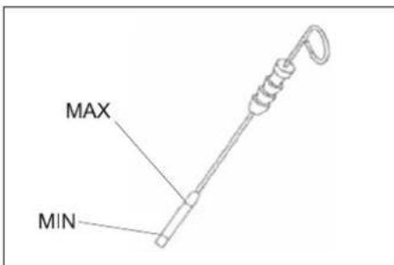
The oil level must be between the MIN and MAX marks. If the oil level is below the MIN mark, add engine oil. The engine must not be running above the MAX mark. Open the oil filler cap. → Fill with engine oil. See the technical data chapter for the oil type and quantity. Close the oil filler cap. → Let the engine run for at least 5 minutes. → Check the engine oil level.
Engine oil level, engine oil change, precautions
Danger of burns from hot oil!
→ Let the engine cool down. → Place a suitable container under the engine. → Let the engine cool down.
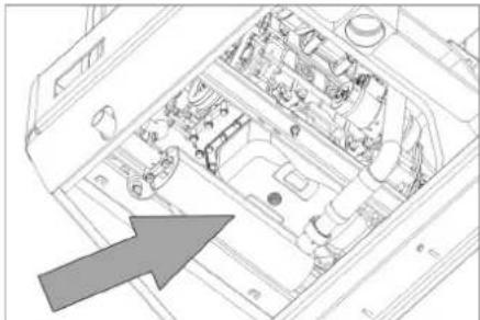
Remove the oil drain plug. Open the oil filler cap. Drain the oil.
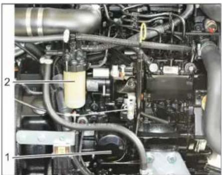
1. Oil filter on the engine 2. Oil filter wrench. Remove the oil filter. → Clean the mounting surface and the sealing surface. → Lubricate the gasket of the new oil filter with oil before installation. → Install the new oil filter and tighten it by hand. Tighten the oil drain plug together with the new gasket. Tightening torque: 25 Nm → Fill with engine oil. See the technical data chapter for the oil type and quantity. Close the oil filler cap. Let the engine run for about 10 seconds. Check the oil level.
Checking the fuel filter
→ Check the fuel filter for clogging. → If necessary, clean or replace the fuel filter.
Replacing the fuel filter
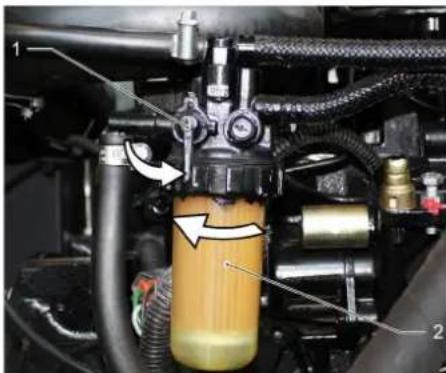
1. Fuel shut-off valve
2. Fuel filter
Close the fuel shut-off valve. Remove the fuel filter and replace it.
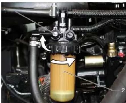
1. Fuel shut-off valve
INSTRUCTIONS
Before starting the engine, check the fuel level.
Turn the fuel valve to the ON position. → Turn the fuel valve to the ON position at the moment of starting. Open the fuel tap.
Drain the condensate water from the fuel filter.
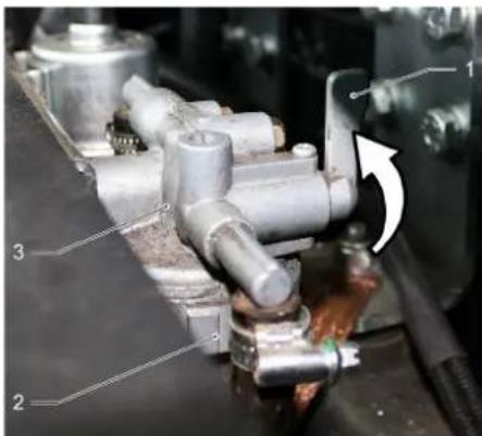
1 Fuel tap 2 Fuel filter 3 Water separator. Close the fuel tap. Unscrew and drain the fuel filter. Tighten the fuel filter. Open the fuel tap.
Checking the level of hydraulic oil. Topping up hydraulic oil.
INSTRUCTIONS
The reservoir must not be completely empty. Open the filler cap.
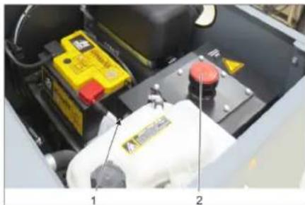
1 Oil dipstick for hydraulic oil 2 Filler cap for hydraulic oil. → Check the level of the hydraulic oil through the sight glass. The oil level must be between the marks "MIN" and "MAX". If the oil level is below the "MIN" mark, top up the hydraulic oil. Unscrew the filler cap. → Clean the filler neck. → Top up the hydraulic oil. See the oil type in the technical data. Tighten the filler cap.
Checking the hydraulic system. INSTRUCTIONS
The hydraulic system may only be serviced by Kärcher service.
→ The locking screw must be blocked. Starting the engine. Check all hydraulic connections for leaks.
Checking the level of the coolant.
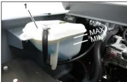
Antifreeze connection
Check the oil level regularly. → Check the oil level in the compensator for antifreeze. The correct oil level of the antifreeze must be between the MIN and MAX marks.
Check the water cooling and the cooling of the hydraulic oil
DANGER
Danger of burns from hot parts!
Let the water pump cool down for at least 20 minutes. The water cooling level is checked on the compensator for antifreeze. Open the cover, check the coolant level. → Clean the cooler. Remove any blockages with a soft brush, air under pressure, or low water pressure. → Check the cooler fins and the water source for tightness. → Clean the fan.
Check the metal jacket
Start the motor. → Move the lever to the end position. → Turn off the motor. → Lock the safety catch. Then set the pre-set height for high lifting. Remove the centering pins from the metal jacket. → Take the pre-set channel. Start the motor. → Lower the lever to the end position. → Turn off the motor.
Replace the metal jacket
1 Key 2 Side cover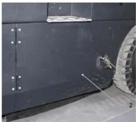
→ Lift the lever for the pre-set channel. Open the side cover with the key.
1 Retaining bracket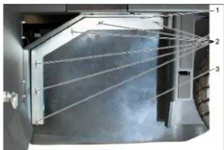
2 Wing nut
3 Side reinforcement
Unscrew the wing nuts. → Remove the retaining bracket. Turn the side reinforcement outward. Unscrew the fastening of the metal jacket and tilt the fastening outward. → Remove the metal jacket.
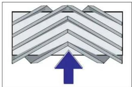
Mounting position of the metal jacket relative to the direction of travel (arrow on the cover) Note: When mounting a new metal jacket, pay attention to the position of the complete set of the mesh.
Mounting the new metal bank. Before mounting the metal bank, you must place it in the supports of the metal bank on the middle floor slab.
Note: After mounting the new metal bank, the reflector for the meter must be adjusted.
Checking the adjustment of the reflector for the meter on the metal bank
Note: The reflector for the meter is factory-set at 80 mm, but it can be adjusted steplessly during wear of the metal bank.
Check the pressure on the hoses. → Disconnect the suction hose. → The metal machine must be placed on a flat and solid surface, covered with dust or debris, so that it can be seen. Adjust the metal bank control lever (1) backwards: the metal bank lowers.
Control lever for the metal bank (3) backwards: the metal bank lowers.
Leave the metal bank to work for about 10 seconds. → Control lever for the metal bank and the side metal (1) in the middle.
Control lever for the metal bank (3) forward: the metal bank rises.
→ Drive the unit on a flat surface. → Check the reflector for the meter.
The shape of the reflector for the meter must form a right rectangle with a width of 80-85 mm.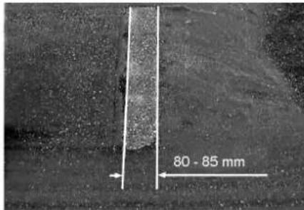
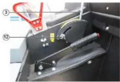
Open and adjust the limit switch for the wear adjustment (12).
Limit switch up: tighter reflector for the meter.
Limit switch down: wider reflector for the meter.
Close the limit switch again. → Check the reflector for the meter on the metal bank again, as described.
Checking the adjustment of the reflector for the meter on the side metal
→ Move the page guides. → Place the machine on a flat surface, covered with dust or similar, so that it does not wobble. The page guides are used for control and should remain in operation for 10 seconds. → Move the page guides. Turn the knob to the rear. Check the metal detector.
The width of the metal detector reflector must be between 40-50 mm.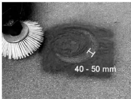
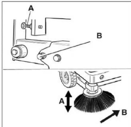
Correct the metal detector reflector with the adjusting bolt. Check the metal detector.
Adjusting the page guides
DANGER
Danger of electric shock!
2 Air filter housing
→ Remove the page cover. → Remove the air filter housing. → Replace the air filter element.
Note: Possible clogging of the air outlet (see illustration).
Removing the centrifugal fan
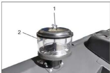
1 Wing nut 2 Centrifugal fan
Unscrew the wing nut from the centrifugal fan. Remove the centrifugal fan.
Replacing the fuse
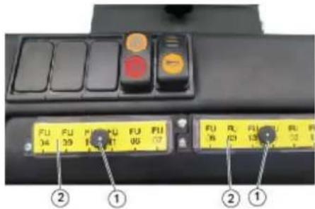
1 Fuse holder 2 Fuse cover. Unscrew the fuse holder. Open the fuse cover. Check the fuse → Replace defective fuses. Note: Use only fuses with the correct fuse rating.
Note: The fuse FU 01 is located in the device compartment.
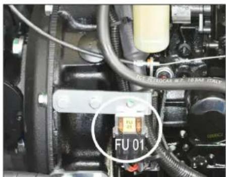
| FU 01* Паловни рedingимпел 60 A | |
| FU 02 Клakson 25 A | |
| FU 03 Рредно рelen Мулиchosункоюнада Индikацяя | 10 A |
| FU 04 Аварийся ламма за Сбетене наокою | 5 A |
| FU 05 Рредно рelen Забавке въь врeme- TO | 25 A |
| FU 06 Кынна на ворача (on- цяя) Чистачка на съknata | 10 A |
H.Jenner Chairman of the Board of Management
Director Regulatory Affairs & Certification
S. Reiser
Alfred Karcher SE & Co. KG
71364 Winnenden (Germany)
Tel.: +49 7195 14-0
Fax: +49 7195 14-2212
Winnenden, 2020/01/01
www.kaercher.com/REACH
Warranty
Position 0: Switch off the engine
Position 1: Switch on
Position 2: Start the engine
10 Engine speed adjustment Throttle cable 11 Parking brake 12 Wear adjustment / blow-off area setting on side brush
Pedals
Figure
General safety instructions
△DANGER
Risk of injury!
Product: Vacuum-sweeper with seat
Type: KM 120/250 RD 1.186-000.0
H. Jenner Chairman of the Board of Management
S. Reiser
Director Regulatory Affairs & Certification
71364 Winnenden (Germany)
Tel.: +49 7195 14-0
Fax: +49 7195 14-2212
Winnenden, 2020/01/01
www.kaercher.com/REACH
Warranty
H. Jenner Chairman of the Board of Management
S. Reiser
Director Regulatory Affairs & Certification
Authorized to compile the documentation:
S. Reiser
Alfred Karcher SE & Co. KG
Alfred-Karcher-Straße 28-40
71364 Winnenden (Germany)
Tel.: +49 7195 14-0
Fax: +49 7195 14-2212
Winnenden, 2020/01/01
General instructions. LT 1
www.kaercher.com/REACH
Warranty
Winnenden, 2020/01/01
Table of contents UK 1
Environmental protection UK 1
Introduction. UK 1
Warranty. UK 1
Maintenance and spare parts UK 1
Parts. UK 1
Symbols in the manual . . . UK 1
Symbolic device..UK1
Proper use. UK 2
Improper use
Proper use UK 2
Surface treatment...UK 2
Safety rules UK 2
Power supply. UK 3
Instructions for installation of the UK 3
Control element
Keyboard. UK 4
Assembly of the printing
machine UK 4
Control panel. UK 4
Real UK 4
Control indicators and
displays. UK 5
Preparing for operation. UK 5
Lock/Release
standby mode. UK 5
Pressing the initial
machine without power
BODa. UK 5
BBeHnB E KcNlyatauio UK 5
3araJIbHI Bka3iBKN .UK 5
Ipebeipka i texhiye 6cbny
roByBaHHa UK 5
3anpaBka. UK 5
Ekcnnyataia. UK 5
HaCTpoITnIonoXeHHa
CnDINHBAODIy. UK 5
3anyctntnpncptpi. UK 5
PepecyBaHHHa npHai UK 6
PiimitaHHa. UK 6
CnpoKHTn pe3epByap
ДЯ CMITТ... UK 6
BmKHyTn npntpiuUK 7
Transportation UK 7
Storage and commissioning
Operation. UK 7
Maintenance and technical
service. UK 7
General instructions. UK 7
UK 7
Maintenance frequency UK 7 Preventive maintenance. UK 8 Troubleshooting. UK 14 Technical specifications. 15 Declaration of conformity...UK 16

Before using your device, read
the original operating instructions, follow them strictly, and keep them for future use and for subsequent owners.
General instructions
If any damage occurred during transportation, notify the store where you purchased the device.
The marking of the device, warning signs, and data plates contain important instructions for safe operation of the device. Together with the instructions in this manual, general safety rules and regulations for the prevention of accidents by legislative bodies must be observed.
Environmental protection

Materials are recyclable and can be reused. Please do not dispose of packaging materials with household waste; hand them in for recycling.
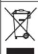
Old devices, materials, and accessories that can be recycled should be handed over to a collection point for secondary raw materials. Therefore, please dispose of old devices through specialized collection systems.
Do not allow engine oil, grease, or gasoline to enter the soil or water. Protect the environment and dispose of used oil in an environmentally friendly manner.
Instructions for use of components (REACH)
Current information on components is available on the website at:
www.kaercher.com/REACH
Warranty
In each country, the warranty terms published by the responsible sales company apply. We will eliminate any malfunctions of the device free of charge within the warranty period, provided they are caused by material defects or manufacturing errors. In the event of a warranty claim, please contact the dealer or the nearest authorized service center with proof of purchase.
Accessories and spare parts
DANGER
To avoid danger, repair and installation of spare parts must only be carried out by authorized service centers.
Only use accessories and spare parts approved by the manufacturer for use with the device. Original accessories and original spare parts guarantee that the device will operate safely and correctly. Further information on spare parts can be found on the website www.kaercher.com in the Service section.
Symbols in the manual
DANGER
Warning about immediate danger that can lead to serious injuries or death.
WARNING
Danger of electric shock! Improper use may result in minor injuries.
DANGER
Warning about potential dangerous situation that may lead to minor injuries or material damage.
WARNING
Warning about a potentially dangerous situation that may cause material damage.
Symbols on the device
| SSS | Hebezeileka oniky ob zapary noeepxHIO!! Paped noyam- kom ocbnyzoeyehnna npuna- dy cniD damu buxnonhi mpybi oxolodumcib. |
| Pobomu i3 pucmpoem cniD 3aBXdu npobodmu minbku y eidiNoeiedhux 3axuchux py- kauzix. | |
| Hebezeileka zamuckanha pyxNubUmu demalmaMu ab- momobiln | |
| Hebezeileka odepXaHnna mpaemu biD pyxNubux ya- cmun. He mopkamucj. | |
| Hebezeileka nOgeki. He do- nyckamu ECMokmyeaHnna na- laiochux abo mniouchux ppeD- memie. | |
| 3amuck dne naHcuOza / moy- ka pozmawyeahnna kpaHy | |
| Tochu niDiyomy dne domkpa- ma | |
| Мakcumальнихши по- верхни р pu руci 3 ni diямUM Буннером. | |
| У наразмку руху доч- саemsberя зда по схлaxdo 18%. | |
| Небезпека поковоженя! Пионец у сільчрп ром uea- MU He nompiбно. |
Correct use
The cleaning machine is intended for professional use and for cleaning surfaces, for example, in the following areas:
Parking lots, building sites, gas stations, hotels, retail areas, warehouse areas, sidewalks. Use the cleaning machine only in accordance with the operating instructions. Any other use is considered improper. The manufacturer is not liable for damage caused by improper use; the user bears the risk. It is forbidden to make modifications to the device. The cleaning machine is intended only for work on surfaces specified in this operating manual. The machine may only be moved on surfaces approved for use of cleaning machines by the manufacturer or its representative. The following rule applies: do not allow the device to come into contact with easily flammable materials (danger of fire/explosion).
Improper use
It is forbidden to vacuum/use explosive or flammable gases, undiluted acids and solvents! This applies to gasoline, paint thinners and fuel oil, which can form explosive or flammable vapors when mixed with vacuumed air, as well as acetone, undiluted acids and solvents, as they corrode device materials. It is forbidden to vacuum/use reactive metal dust (e.g., aluminum, magnesium, zinc) in combination with alkaline or acidic agents.
Do not vacuum/use hot or glowing objects. The device is not intended for collecting substances hazardous to health. It is forbidden to operate the device in enclosed rooms. It is forbidden to store the device in hazardous areas. It is forbidden to use the device in potentially explosive atmospheres. It is not allowed to take along accompanying persons. It is not allowed to push, pull, or transport objects with this device.
Surface cleaning
Brush head for cleaning floors (standard)
Safety rules
→ During installation and operation, the device must be protected from frost. It is forbidden to use it at ambient temperatures below 0°C. In case of device malfunction, contact your Karcher service center. → Before use, check the device and accessories for proper condition and safety. If the accessories are in unsatisfactory condition, the device must not be used. → When using the device in unsafe conditions (e.g., near flammable materials), it is necessary to follow the relevant safety instructions. It is forbidden to use the device in explosive atmospheres.
SAFETY
Danger of injury!
Do not use the device without the protective cover in areas where there is a risk of falling objects on the operator. The user must use the device only in accordance with the instructions. The instructions take into account the operator's safety, but when working with the device, attention must be paid to third parties, especially children. → It is also necessary to comply with all rules and regulations regarding transport vehicles. → Before starting work, the operator must ensure that all necessary devices are in place and functioning properly.
The operator of the device is responsible for accidents involving third parties or property. → Ensure that the operator wears appropriate clothing. Loose clothing should be avoided. → Before each use, check the device for damage (e.g., on the housing). Ensure sufficient visibility! Do not operate the device without proper lighting while the motor is running. Maintenance personnel are allowed to operate the device only after it has been switched off, the device has been secured against accidental restart, and the key has been removed. → To avoid unintentional use of the device, remove the key. → The device must only be used as described in the instructions for its intended use, and any other use is prohibited. → This device is not intended for use by persons (including children) with reduced physical, sensory, or mental capabilities, or lack of experience and knowledge, unless they are supervised or instructed by a person responsible for their safety. Children must be supervised to ensure they do not play with the device.
CAUTION
Danger of electric shock! Do not allow the device to come into contact with water or moisture, as this may cause a short circuit.
Safety instructions for driving mode
SAFETY
Danger of tipping! Check the stability of the surface before driving.
CAUTION
Danger of accident, danger of electric shock!
→ The speed of movement must be adapted to the prevailing conditions. Danger of tipping when driving on steep slopes. → When driving, descending slopes of up to 18% is permitted. Danger of tipping on unstable ground. → It is allowed to move the device only on designated routes.
Danger of tipping over when using the appliance on steep slopes. → In directions perpendicular to the direction of travel, tilting of the device is only permitted on slopes up to max. 10%
Risk of injury from internal combustion engine
→ Do not use the device at altitudes above 1200 m.
△Caution!
Danger of injury!
Exhaust gases must not be blocked. Do not cover the exhaust opening and do not touch it (danger of burns). → Do not touch or hold the drive cables (danger of burns). Exhaust gases are toxic and harmful to health; inhaling them is prohibited. → After switching off the engine, wait 3-4 seconds before touching it. During this time, stay away from the drive area.
Machines with forklift pockets
DANGER
Danger of injury!
→ When working with the forklift pockets, they must be fully inserted and secured. Perform work only outside the danger zone.
Risk from protective water shield
NOTICE
The protective shield (water) protects the device from falling large objects. But it cannot protect against tipping over!
→ Before each use, check the protective shield for damage. → In case of damage to the protective shield, even to individual components, the entire protective shield must be replaced. → Any modification of the protective shield and installation of components not approved by Kärcher is not permitted and may impair the function of the protective shield.
Safety instructions for transporting the machine
Remove the device from the charger or from the vehicle's power outlet before cleaning. → When transporting the device, disconnect the battery terminals and securely close the device.
Safety instructions and maintenance
→ Before cleaning and performing maintenance, removing parts or replacing components, the device must be switched off and the plug removed. → When working with electrical equipment, it is necessary to disconnect the battery.
First disconnect the negative terminal, then the positive terminal.
Connection is made in the reverse order. First connect the positive terminal, then the negative.
→ Do not allow the device to be exposed to water jets or high-pressure cleaners (risk of short circuit and other damage). → Repair work may only be carried out by authorized service centers or specialists familiar with all important safety rules. → Perform a safety check in accordance with local regulations for stationary devices used in industry. → Work with the device must be carried out in special gloves.
Purpose
The machine that pumps directs the oil directly into the oil collection reservoir.
- The pump directs the oil directly into the oil collection reservoir. - The pump pumps oil from the surface of the oil being pumped and leaves the oil zone of the pump's working area, which is being pumped. - The pump is equipped with a filter for the oil.
Instructions for unpacking
DANGER
Danger of injury and damage!
→ When unpacking, pay attention to the device. → Do not use force, as the device may be damaged.
Empty weight (transport weight) 880 kg*
- With the installation kit installed, the device weight becomes, accordingly, significant.
→ Before using the device, use a suitable ladder or crane. → When using the ladder, pay attention to the following: empty passage 70 mm → The device is installed on the floor; it is necessary to build a frame from the supplied boards for the ladder. The instruction sign is on the inside of the cover.
Important: Each board must be secured with 2 screws.
Remove the right and functional unit
A
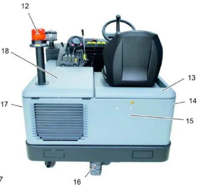
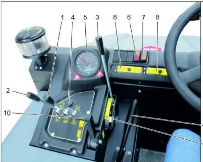
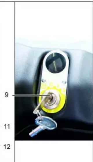
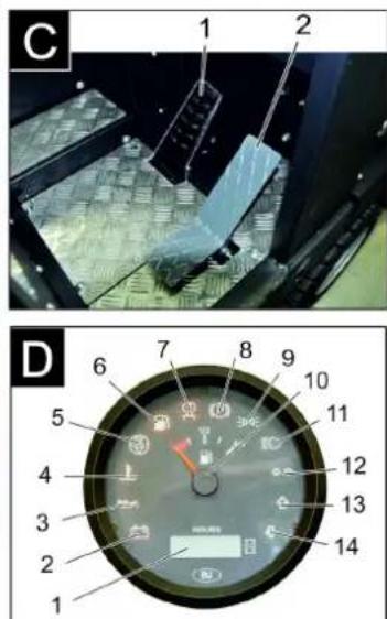
Image of the washing machine control panel
Figure A
1 Tank lock 2 Drain hose (with contact switch) 3 Control wheel 4 Centrifugal separator 5 Locking of the device cover 6 Device cover 7 Outlet hose, right 8 Front wheel 9 Inlet hose, supply 10 Mounting bracket 11 Factory plate 12 Ribbed hose 13 Device cover right 14 Cover, right 15 Rear housing 16 Rear wheel 17 Cover, left 18 Left cover (left cover)
Figure
1 Control lever for the cylinder and the piston rod. Lever forward: cylinder rod extends and lever backward: cylinder rod retracts 2 Control lever for the tank for collecting waste. Raise/lower the waste collection container 3 Control lever for the cylinder rod. Extend/retract the cylinder rod 4 Control lever for the tank cover. Open/close the tank cover 5 Control and indicator lamps 6 Filter cleaning and emptying
Middle position: Filter cleaning and pump on.
Rear position: Pump on.
Front position: Filter cleaning pump on.
7 Sound signal switch 8 Spare parts 9 Spare parts lock
Operating conditions for commissioning: Preliminary run
Position: Pump on
10 Regulator of the number of revolutions of the drive engine 11 Stop signal lamp 12 Regulator of the value / level of the hydraulic fluid
Handle
Handle
1 Pedal brake 2 Pedal accelerator forward/reverse
Control indicators and lamps
Handle D
1 Working headlight 2 Signal lamp for parking brake 3 Signal lamp for oil pressure 4 Signal lamp for water temperature, coolant 5 Fuel tank 6 Signal lamp for fuel reserve 7 Control indicator for opening 8 Control indicator (not connected) 9 Control indicator for parking/brake lights (optional) 10 Indicator for faults 11 Not working, lights up only when starting the engine (self-diagnosis) 12 Fuse 13 Fuse 14 Fuse
Before starting work
Lock/Release the parking brake
Release the parking brake by pressing the brake pedal. Lock the parking brake by pressing the brake pedal.
Towing the washing machine without its own drive
Instruction
The procedure is necessary when the device needs to be moved, transported, or loaded onto a transport vehicle without using its own drive.
Attention
It is forbidden to use the device without reading the instructions, at a distance of less than 10 km/h.
Turn the key to the right → turn it on. Turn it off.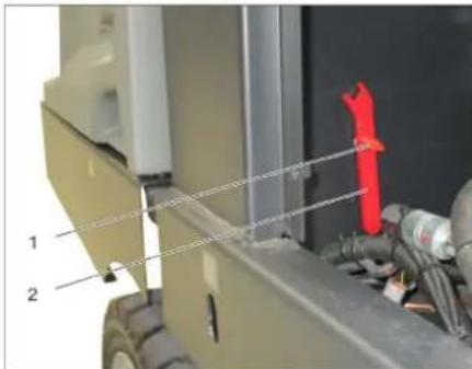
Adjusting the key from the tank
→ Loosen the nut with a wrench (open the free stroke), until the device can be moved easily. → IMPORTANT: after moving, tighten the nut again (close the free stroke) to the position.
Commissioning
General instructions
→ Before commissioning, read the manufacturer's operating instructions for the device and take into account the safety instructions. Install the device on a flat, clean surface. → Turn the key to the off position. Secure the column to the floor system.
Inspection and maintenance
Control lever for the hydraulic cylinder (3) down: the hydraulic cylinder lowers.
Control lever for the reservoir valve (4) open: the reservoir valve opens. → Close the valve:
Control lever for the hydraulic and pneumatic cylinders (1) forward: the hydraulic cylinder extends, the pneumatic cylinder extends and lowers.
Control lever for the hydraulic cylinder (3) up: the hydraulic cylinder raises.
Empty the reservoir of the compressor
SAFETY
Safety during operation
→ Emptying the collection tank: Danger of tipping! → Emptying the tank should be done on a level surface.
△DANGER
Danger of tipping!
Never tilt the machine or the emptying system. Do not stand under the raised tank.
WARNING
Danger of injury and damage!
→ When emptying, material may splash. Wear appropriate protective clothing.
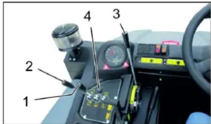
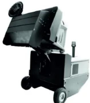
→ To raise the cylinder: Move control lever 1 to center and control lever 3 forward. → To close the tank lid, move control lever (4) back. → To lower the tank for collecting waste, move control lever for collecting waste (2) back. → To approach the waste collection tank, secure the parking brake. → To open the tank lid, move control lever for tank lid (4) forward, empty the waste tank. → Close the tank lid, move control lever for tank lid (4) back to the end position. Release the parking brake. → To move away from the waste collection tank. → To lower the waste collection tank to the end position, move control lever for waste collection tank (2) forward.
Switch off the device
→ To raise the cylinder: Move control lever 1 to center and control lever 3 forward. → To close the tank lid, move control lever (4) back. → Fully move the adjusting knob for the drum speed back. → Press and hold the brake pedal. Secure the parking brake.
→ Turn the ignition key to position "0" and remove it from the lock.
Transport
DANGER
Risk of injury during transport!
Secure the device with suitable lashing straps (transport straps) for transport or on transport vehicles. → When transporting the device on transport vehicles, observe the applicable national regulations for securing loads. The ignition key must be turned to position "0" and removed from the lock. Secure the parking brake. → Fasten the device to the provided attachment points (4 points) using suitable tensioning devices. Secure the device by placing chocks under the wheels. → During transport, the battery must be disconnected from the main switch.
Maintenance and repair
General instructions
ATTENTION
Danger of injury!
→ The type of filter must not be cleaned. → Repair work may only be carried out by authorized service personnel or specialists who are familiar with all important safety regulations. → Devices used commercially in accordance with local regulations require safety inspections according to VDE 0701. Install the device on a level surface. → Insert the mains plug into the "0" position and pull it out of the lock. Lock the stand column system.
DANGER
SURFACE
Danger of injury!
→ Do not allow the device to be exposed to rain or water jets under high pressure (danger of short circuit or injury).
Inside the device
DANGER
Danger of injury!
→ Wear protective mask against dust and protective goggles. Check the device for leaks. → Operate the device only under pressure.
Outside the device
Clean the device using a dry cloth and a soft brush.
Note: The use of personal protective equipment is mandatory.
Maintenance frequency
Note: The operating hours counter indicates when maintenance is due.
Maintenance performed by the customer
Note: All maintenance work on the customer side must be carried out by qualified specialists. If any issues arise at any time, you can contact the specialized trade organization of the Kärcher company.
Maintenance work:
→ Check the fuel tank for damage. → Check the oil level in the engine. → Check the coolant level in the radiator.
→ Check that the belts are tensioned and show no signs of wear. → Check the fuel filter. → Check the centrifugal separator and the air filter, clean if necessary. → Check the condition of all control elements. → Check the device for damage.
Detailed maintenance
Clean the water radiator. Clean the oil radiator. → Check the oil level. → Check the pressure in the hydraulic system. → Check the hydraulic oil level. → Check the V-belts for wear and replace if necessary. → Check and lubricate the reservoir cover.
Maintenance after 50 operating hours:
→ Drain the water from the water separator (if equipped).
Maintenance work that is required:
Replace the V-belts. Adjust or replace the belts. Replace the fuel filter. Replace the air filter.
Note: For detailed information, see the "Maintenance" section.
Maintenance and servicing is carried out by the service department.
Insert: To preserve rights and warranty servicing, work on technical and professional maintenance during the warranty period must be performed consistently by the Karcher service department in accordance with the maintenance instructions.
Maintenance after 50 hours of operation:
→ Technical maintenance must be performed in accordance with the technical inspection schedule of the service department.
Technical maintenance after 250/500/1000/1500/2000 hours of operation:
→ Technical maintenance must be performed in accordance with the technical inspection schedule of the service department.
Professional work
Preparation:
Install the machine, switch off the engine, clean the surfaces. → Turn the ignition key to position "0" and pull out the lock. Secure the parking brake system.
General safety instructions DANGER
Danger of injury!
→ When working with the reserve tank for collecting dirt, use protective equipment. Perform protective measures outside the danger zone.
1 Hold the reserve tank handle from below and lift it up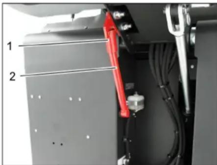
→ Lift the reserve tank upward to empty the dirt tank and insert it into the holder (reserve tank).

Be careful, do not allow motor oils, lubricants, diesel fuel, and gasoline to enter the environment. Be careful, protect the soil and dispose of used oils properly, without polluting the environment.
Battery safety warnings
When working with batteries, follow the following safety instructions:

Follow the instructions on the battery and in the user manual for the device!

Wear eye protection!

Do not allow children to access batteries!

Explosion hazard!

Prohibited: short-circuiting, igniting, disassembling, or puncturing batteries, and exposing them to heat sources!

Chemical burn hazard!

First aid!

Check the marking!

Dispose of properly!

Do not dispose of batteries in household waste!
DANGER
Explosion hazard!
Use only batteries with protective covers. The cover protects in case of damage.
DANGER
→ Do not place tools or similar objects on the battery. Danger of short circuit.
DANGER
Danger of electric shock!
→ Do not allow contact with the battery terminals. After working with the charger, wash your hands.
DANGER
Danger of fire and explosion!
It is forbidden to charge the battery in an explosive atmosphere. The room where the batteries are charged must be well ventilated, so when charging, gases are released that can explode.
DANGER
Danger of chemical burns!
→ If electrolyte comes into contact with eyes or skin, rinse with plenty of clean water. → After that, consult a doctor immediately. Both actions are mandatory.
Install the battery and connect the charger
The device is supplied with a battery, but it is not charged.
1 Positive pole 2 Pole cap 3 Negative pole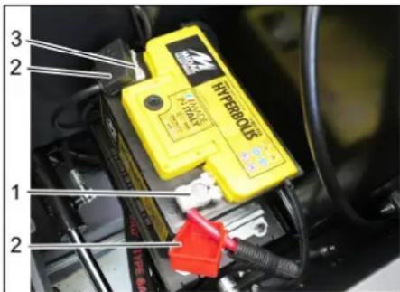
Connect the charger to the battery terminals. Then place the battery on the battery tray. Connect the red cable to the positive (+) terminal. Connect the black cable to the negative (-) terminal. Install the terminal caps. Check that the battery is securely fastened in the tray and terminals.
Check the electrolyte level in the battery and correct it (only in batteries that do not require maintenance with plugs for battery cells).
CAUTION
Risk of injury!
Batteries that contain acid: carefully check the acid level. Check the battery cells. Use a hydrometer to take a sample from each cell. The electrolyte density of a fully charged battery is 1.28 kg/l at 20°C. The electrolyte density of a partially charged battery is between 1.00 and 1.28 kg/l. In all cells, the electrolyte density must be the same. Test the electrolyte in all cells. If the acid level is too low, fill the cells with distilled water to the mark. Charge the battery. Tighten the battery cell plugs.
Charging the battery
DANGER
Danger of injury! When working with batteries, follow the safety rules. Follow the operating instructions of the charger.
DANGER
Risk of injury! Charge the battery only with a suitable charger.
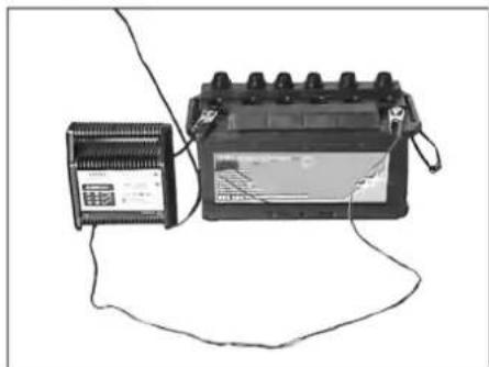
Remove all battery cell plugs (only for batteries that are not maintenance-free). Connect the red cable (+) of the charger to the positive terminal of the battery. Connect the black cable (-) of the charger to the negative terminal of the battery. Insert the mains plug into the socket and switch on the charger. The battery should be charged with a charger with a low current.
After charging the battery, disconnect the charger from the mains first, then from the battery. Tighten the battery cell plugs (only for batteries that are not maintenance-free).
Removing the battery
Disconnect the negative terminal first, then the positive terminal. Place the battery on the battery tray. Remove the battery from the battery tray. Dispose of the battery according to local regulations.
Check the brake fluid level and top up if necessary.
Danger! Direct current!
→ When working with the reserve tank, follow the safety instructions. Perform protective measures in the danger zone.
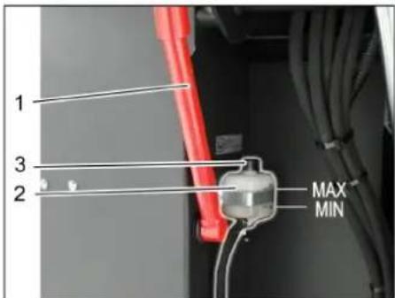
1 Reserve tank cap 2 Reserve tank for coolant 3 Filler neck →Unscrew the reserve tank cap for collecting coolant, see chapter, Draining the reserve tank for collecting coolant → Check that the coolant level in the reserve tank is sufficient. Indicator
The coolant level should be between the MIN (min.) and MAX (max.) marks.
→ If necessary, top up with coolant, which is available as an accessory.
Checking the oil level
Danger of burns! → Let the engine cool down. → Check the oil level in the engine only after the engine has been switched off for a few minutes.
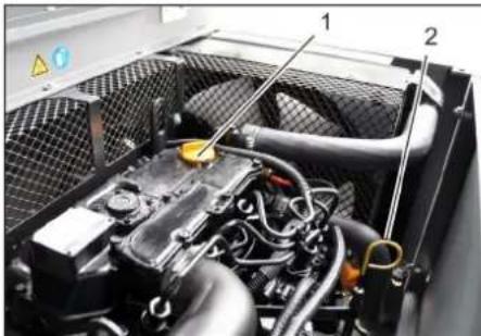
1 Oil filler cap (engine)
2 Oil level indicator
Pull out the oil dipstick. → Wipe the indicator and insert it again. → Pull out the oil level indicator. Read the oil level. Insert the oil level indicator again.
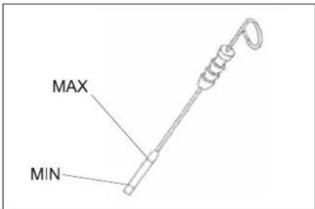
-The oil level must be between the "MIN" and "MAX" marks. - If the oil level is below the "MIN" mark, top up with oil - Do not fill oil above the "MAX" mark. → Unscrew the oil filler cap. Add engine oil. See chapter "Technical data". Close the oil filler cap. Wait at least 5 minutes. → Check the oil level in the engine.
Changing the engine oil and filter. OVERVIEW
Danger of burns from hot oil!
→ Let the engine cool down. → Drain the oil from the engine for at least 6 minutes. → Dispose of the oil properly.
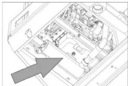
→ Turn the oil filler cap. → Remove the oil filler cap. Remove the oil.
1 Oil filter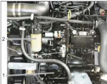
2 Fill with oil
Remove the oil filter. Clean the sealing surfaces. → Before installing a new oil filter, lubricate the new oil filter gasket with oil. Install the new oil filter and tighten it by hand. Tighten the filler cap. Fill with engine oil. The oil type and level are specified in the "Technical Data" chapter. Close the oil filler cap. → Run the engine for approximately 10 seconds. → Check for leaks.
Check the oil level.
→ Check the oil level for contamination. → If necessary, clean the oil filter and the filter housing, and replace the oil filter if necessary.
Replacing the fuel filter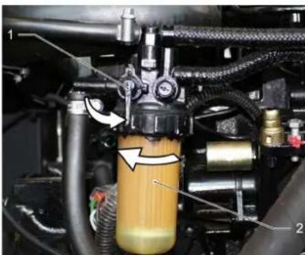
1 Fuel shut-off valve 2 Fuel filter Close the fuel shut-off valve. Remove and replace the fuel
01 Maintenance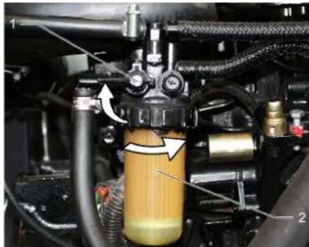
2 Fuel filter replacement
Before replacing the fuel filter, drain the diesel fuel.
→ Install the new fuel filter. Tighten the fuel filter by hand with a torque of 20 Nm.
Open the fuel shut-off valve
Drain condensate from the water separator of the diesel fuel
1 Fuel shut-off valve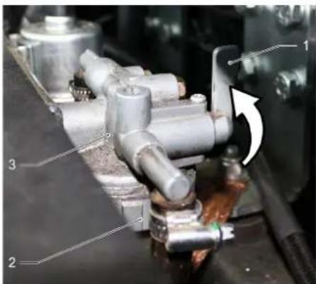
3. Coolant
Close the drain valve. Turn the filler cap and remove it. → Remove the filler cap. Open the drain valve.
Checking the brake fluid level and topping it up
WARNING
The fluid reservoir must not be empty.
Open the filler cap.
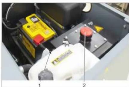
1. Brake fluid reservoir 2. Cap, brake fluid filler opening → Check the brake fluid level in the visible window. - The fluid level must be between the "MIN" and "MAX" marks.
- If the fluid level is below the "MIN" mark, top up the fluid. Unscrew the filler cap for the fluid. Clean the filler opening. → Top up with the correct brake fluid. The fluid type is specified in the "Technical Data" section. → Screw on the filler cap for the fluid.
Checking the correct installation of the warning
Technical maintenance of the brake system may only be carried out by a service center.
Secure the brake system. Start the engine. → Check the brake lines and connections for leaks.
Checking the coolant level
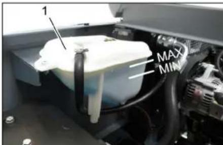
1. Coolant expansion tank
Check the coolant level through the viewing window. → Check the coolant level in the expansion tank.
Check the coolant level in the radiator (min.) and max.
Check the radiator and the coolant level. Safety
Danger of burns from hot surfaces and danger of burns from steam!
The radiator must be cleaned at least every 20 hours. The coolant level in the radiator is checked on the compensation tank of the cooling system. See the chapter "Checking the coolant level". Clean the radiator parts. Remove any dirt with a soft brush, compressed air, or a low-pressure water jet. → Check the radiator and the coolant level. → Clean the fan.
Check the oil level
Start the engine. → Open the drain valve for the oil collection tray. Close the drain valve. Secure the drain valve.
Install the drain plugs for emptying the oil collection tray. → Remove the drain plug, the oil filter, the rope, and the gasket. Install the drain plugs. Start the engine. → Open the drain valve for the oil collection tray. Close the drain valve.
Oil level
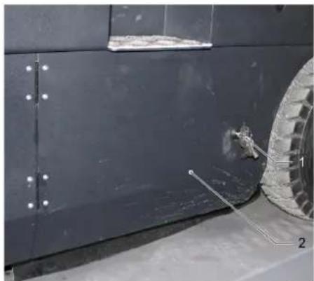
1 Oil filler cap
2 Side cover
→ Lift the oil collection tray and the oil filter using the lifting device. → Open the side cover using the key.
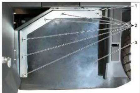
1 Oil filter
2 Union nut with union. Remove the union nuts. Remove the oil filter bracket. Disconnect the electrical connection. → Remove the fastening screws of the oil filter housing, the oil filter, and the gasket. Remove the oil filter.
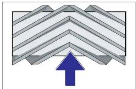
Rotating the oil filter when installing in the direction of rotation (from above)
Note: When installing a new oil filter, pay attention to the position of the chain.
INSTALLATION OF THE NEW VALVE, 10 MINUTES. After installing the new valve, 10 minutes, the new valve must be adjusted.
Indication: After installing the new valve, it is necessary to re-adjust the valve lift.
Checking and adjusting the valve lift for the valve that lifts
Indication: The height of the valve plane is set to 80 mm. The height can be adjusted using the adjusting screw of the valve.
→ Check the pressure in the tires. Turn off the compressor. → Place the machine that lifts on a flat surface, cover the lifting mechanism with a layer of oil or grease. The control lever for the hydraulic and pneumatic cylinders (1) back: the hydraulic cylinder is lowered.
The control lever for the hydraulic cylinder (3) back: the hydraulic cylinder is lowered.
→ Give the hydraulic system time to warm up for about 10 seconds. The control lever for the hydraulic and pneumatic cylinders (1) is set to the center:
The control lever for the hydraulic cylinder (3) forward: the hydraulic cylinder is raised.
→ Give the device time to work. → Check the lifting height.
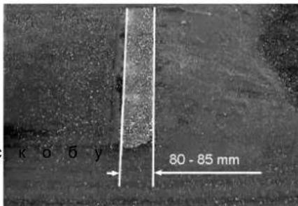
The lifting height must be a uniform rectangle with a width of 80-85 mm.
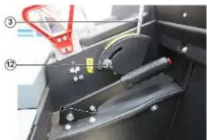
Open and adjust the stop screw of the lowering adjustment device (12).
Stop up: reduces the lifting height.
Stop down: increases the lifting height.
Tighten the screw again. Check the lifting height as described above.
Checking and adjusting the lifting profile for the valve that lifts
→ Press the filter cleaning button. → Install the filter, 10 minutes, with the filter cover, covered with a protective film or copper. Lower the filter and let it work for 10 seconds. → Press the filter button. → Give the rear part a push. → Check the filter area.
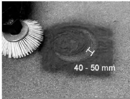
The filter should be cleaned thoroughly with water at 40-50 mm.
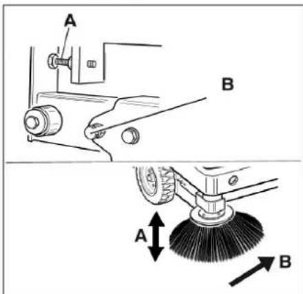
Adjust the position of the filter using the two adjusting screws. → Check the filter area.
Install the filter housing
DANGER
Danger of electric shock!
When working with the condensate collection tank, use protective gloves. Perform work only in the danger zone. → Pull the condensate collection tank upward and secure it with the locking lever. Pull the locking lever upward to release the tank and remove it from the device (locking lever).
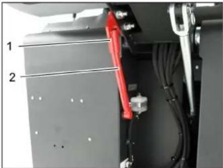
1. Locking lever of the locking lever. 2. Locking lever open. Press the lever, as described in the chapter "Replacing the filter" above. Loosen the two screws on the front plate of the washer. Loosen the screw (SW13) on the front plate of the washer. → Press the filter housing down (surface), until its edge is visible 1-3 mm from the bottom. → Tighten the front plate of the washer. → Repeat on the other side of the device.
Cleaning the filter for the pump
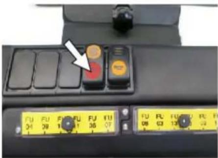
→ Press the filter cleaning button: Check/replace the filter for the pump △ WARNING
Danger of electric shock!
→ When working with the filter unit, wear a mask to protect against dust. Follow the prescribed safety regulations regarding work with dust. → Clean the filter for the pump using the filter cleaning knob. → Drain the condensate collection tank.
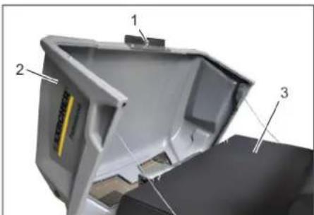
1. Locking the device cover 2. Cover of the device 3. Locking lever
Open the lock. For the device, turn the locking lever clockwise. → Pull the device cover forward.
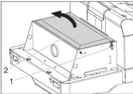
1. Lock, filter cover (2x) 2. Locking lever. Open the lock. Open the filter cover.
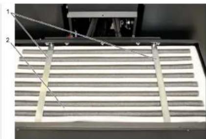
__SUPPIMER__
→ Check the filter, if necessary clean or replace.
Instructions
Replacing the filter may only be carried out by Karcher service technicians. Install and secure the filter hook.
Check and adjust the V-belt
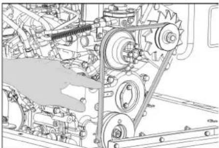
The V-belt at a pressure of 10 bar should deflect approximately 7-9 mm. → Adjustment of the V-belt is carried out by the authorized service center.
Check and replace the air filter
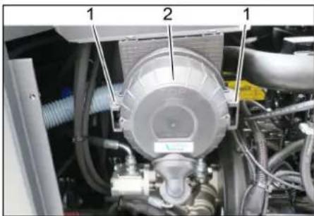
1 Air filter cover
2 Air filter housing
Remove the cover. Remove the air filter housing. Replace the air filter cartridge.
Note: Installation position - ventilation opening facing downwards (see arrow).
Clean the cyclone separator
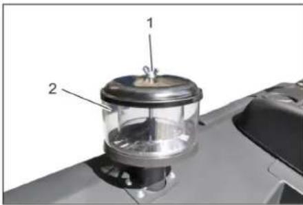
1 Union nut 2 Cyclone separator → Unscrew the union nut on the cyclone separator. Clean the cyclone separator.
Replace the safety valve
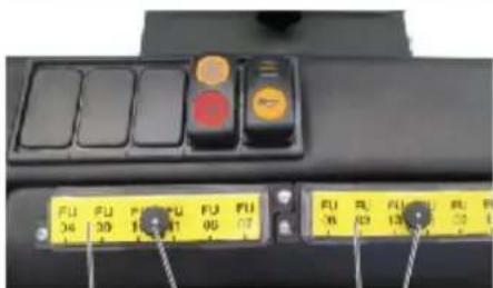

→ Turn such a block with the required torque. Tighten the locking screw on the fuse block. → Check the fuses. Replace defective fuses. Note: Use fuses with the same rating.
Note: Fuse FU 01 is located in the control cabinet.

71364 Winnenden (Germany)
Tel.: +49 7195 14-0
Fax: +49 7195 14-2212
Winnenden, 2020/01/01
Persons who have signed below are authorized to represent the management.
H. Jenner
Chairman of the Board of Management
S. Reiser
Director Regulatory Affairs & Certification
Authorized representative for management
Document:
S. Reiser
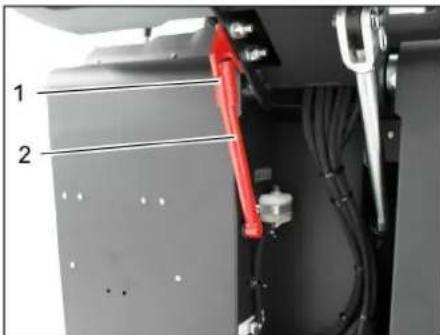
1
2
__SUPPIMER__
Therefore a + b = 3
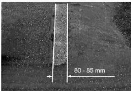
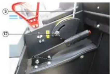
.
E
<.
<.Jx
←jiej
<.
mss10s
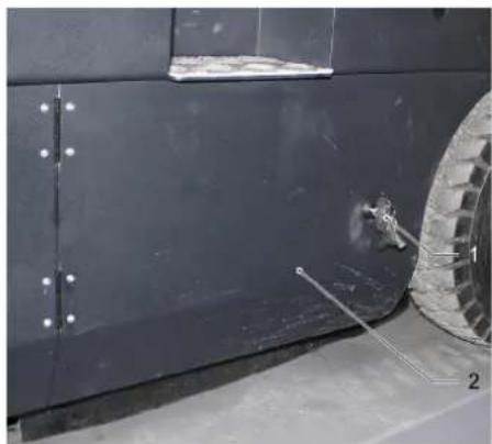
1>laolll 2aui>og
aai aaiyaaag aoalall jgj
2.210 plxuWuy aWbJgwsJz
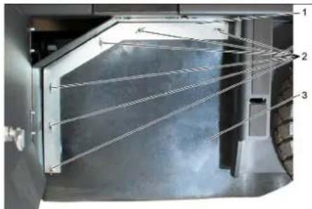
1a
aizoll algoall 2
ai + 1 > a 啄辑
a22all Jolgall 6
.aaolaej
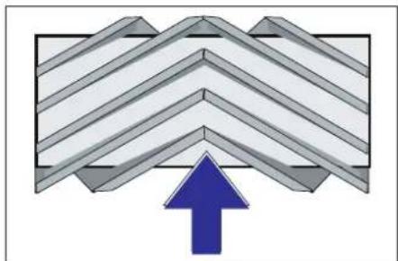
v 1( a 1b 1 + a 2b 2) = v 1b2
BΔ
10/10/10/10/g,( 1/2) > 1/1,( 1/2) < 1/1
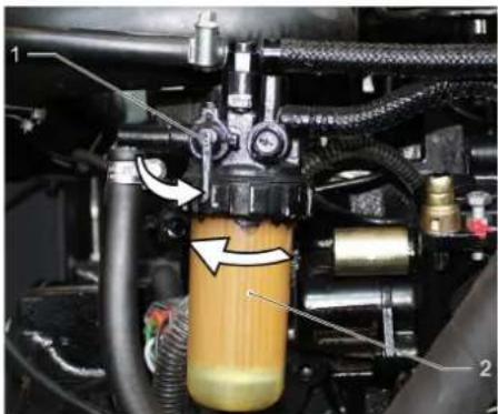
2g9g//µz.
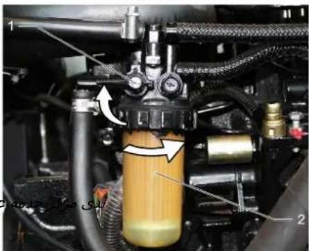
2g3g11 mm 1 °
2
Jow
501
2g 2g 2g 2g 2g
jlaclall Jala aiaaiaaiaaa
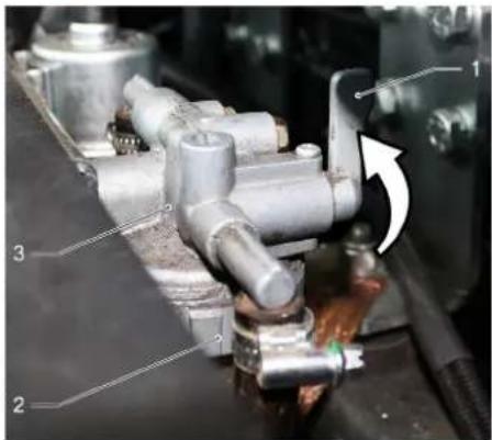
19g 的 mg 之
all 3
g9g11 20 g1c
a2y 9g Jolal j
Jolalwlsb
..g|<
JoJIoSawgSglgjjgjoo>jo
Jll
Jew
10gfoaolaoell Ugsy
y1(x) = y1(1-x)(1-x)
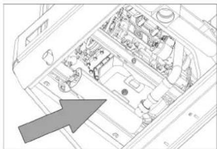
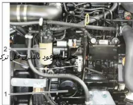
1
ggl 2
jill9 clp
p>yl bawg cunll gogogabaiy p< wjllwcljllp>laic
45j
aabpa>lg221cjjj
1a a24 la 111
∴ a 2 > a 1 > 0 a3 < 0
25:JgJ 1
Jzj jai Jai aasg jjj aeg jaj. aill alol gall
<.wjll
<.J>
2ggljx

\left\{1,2,3\right\}, \left\{1,4,5\right\}, \left\{1,6,7\right\}
ab b2b
Therefore, \(\sin \alpha < 0\), \(\cos \alpha < 0\), \(\tan \alpha > 0\)
Therefore, in right triangle ABD:
- 0 < (x - 2) x > 0. Since x > 1
.
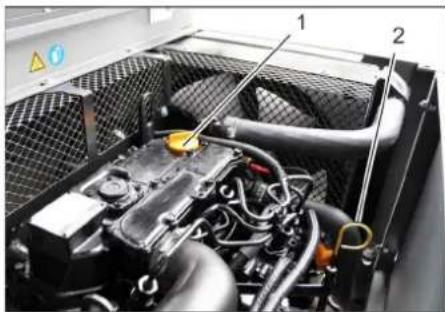
(continued) part 1
part 2
.
.0jll sgswwo wlaLac 2
jll sgwoljawly
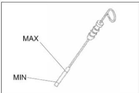
a 1
MAXJILALALc9MIN
.
211 aale 2aay y cuy cuy jy Jyol
MAX
cJlJo eJbE Jg
aJ 1 a000000000
jllss jalal
aOxell jbao slkll Jo Josui
aJlljw←
aJlllsh
4a
1.101111
4b ≥ Δ
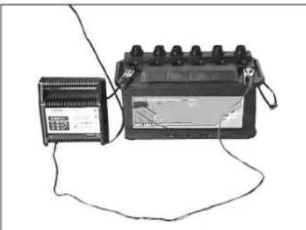
(a)
y 1( 1,2) = 1,y 2( 2)
2ab ≥ 3a
y 1( x) = y 1( 1 - x2)
y1( 1,2) = 1.4,1.6
2011.4.15 2011.4.16
l切l 20 . a 1 · ( b 2 + b1)
k2 = 1/2
y 1| x 22| y 2x 1
b2 + 1 > 3
y 1( x 2 + 1) = y 1( x 2)
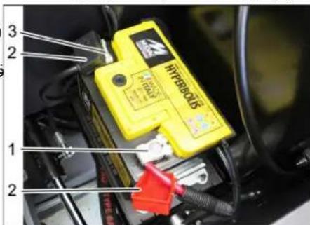
0
.
a 15
"0" 0000000000000000000000000000000000000
ba : Δ
Therefore, m = 3/11
Therefore, m = 3/11
Therefore m = 3/11
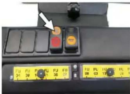
- {a : a ∈ A}
Therefore, angle 1 equals angle 2.
y| {l}_{2} > | {a,b}| < 1
Therefore, a_{i+1} = 1/(2 - a_i) = 2/3, b_{i+1} = 1/(2 - b_i) = 3/4, c_{i+1} = 1/(2 - c_i) = 4/5
A_4^\circ
Therefore, y1(x) = y1(x0) = k0 / (2(k0 + 1))
..
JjJJIg9gJgJU p
Jzll 0
#
glll 100
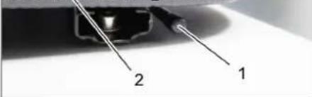
aaal bao gjz 1
jilwll 2
1
aagg jlljol aaoall jx
pLdU asNn no aannnnn n
.
JswjL
gagol jolr
Jolalawgs Jc baoi
←y
10 10
JdJd
abg>do
jgljll jjlojjolilid
aJill aJl Joo 1gJ aJoo w oJ looc g J a>gl
Jaill aJc no aJl
4
y1
yacagalgbolguljllgvlJc
∴ aC = 1/ρs10 d
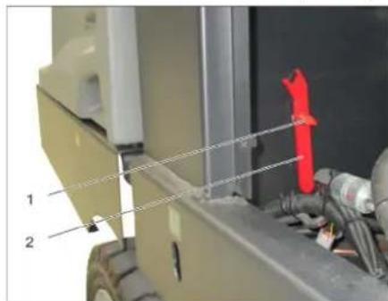
1
2
jawal
.1jj
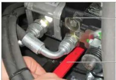
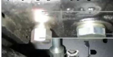
a 1 = 2/3,b 2 = - 4/3,b 3 = 5/8,b 4 = - 7/8
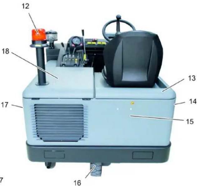
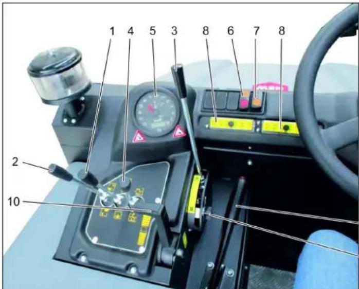
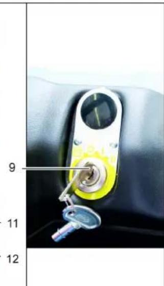

k2 > Δ
a 1 = 1/2,b 2 = - 1/2
( + ) + + = 0
∴ ( 9/a + 9/b - 9/c) y/1 - x = 9/a + 9/b - 9/c
k2 = 2
∴ b 1 = 3/2,b 2 = - 1/2
Therefore, k > 1
Therefore, the area of triangle APQ equals the area of triangle AOB plus the area of triangle OBC.
Therefore, a + b = 3
y
9 111
L 1
g> 111111111
K
Therefore, the area of triangle OBC equals the area of triangle COD plus the area of triangle BOC.
Therefore, j2 > j1.
www.kaercher.com/REACH
Register your product and benefit from many advantages.
www.kaercher.com/welcome ★★★★★
Rate your product and tell us your opinion.
www.kaercher.com/dealersearch
Alfred Kärcher SE & Co. KG
Alfred-Karcher-Str. 28-40
71364 Winnenden (Germany)
Tel.: +49 7195 14-0
Fax: +49 7195 14-2212

- GENERAL NOTES
- ENVIRONMENTAL PROTECTION
- WARRANTY
- ACCESSORIES AND SPARE PARTS
- △DANGER
- SYMBOLS IN THE OPERATING
- INSTRUCTIONS
- DANGER
- WARNING
- CAUTION
- ATTENTION
- SYMBOLS ON THE MACHINE
- PROPER USE
- FORESEEABLE MISUSE
- SUITABLE SURFACES
- SAFETY INSTRUCTIONS
- SAFETY INSTRUCTIONS CONCERNING THE OPERATION
- SAFETY INFORMATION CONCERNING THE DRIVING OPERATION
- APPLIANCES WITH COMBUSTION ENGINE
- APPLIANCES WITH HIGH EMPTYING SYSTEM
- DEVICES WITH OVERHEAD GUARD
- NOTICE
- SAFETY INFORMATION CONCERNING THE TRANSPORT OF THE APPLIANCE
- SAFETY INFORMATION CONCERNING MAINTENANCE AND CARE
- FUNCTION
- UNLOADING TIPS
- OPERATING AND FUNCTIONAL ELEMENTS
- ILLUSTRATION OF SWEEPER OPERATING FIELD
- ILLUSTRATION A
- ILLUSTRATION
- PEDALS
- INDICATOR LAMPS AND DISPLAY
- BEFORE STARTUP
- LOCK/ RELEASE PARKING BRAKE
- MOVING SWEEPER WITHOUT ENGAGING SELF-PROPULSION
- NOTE
- START UP
- INSPECTION AND MAINTENANCE WORK
- DAILY BEFORE STARTING OPERATIONS
- REFUELLING
- OPERATION
- ADJUSTING DRIVER'S SEAT
- STARTING THE MACHINE
- PRE-HEAT
- START THE ENGINE
- DRIVE THE MACHINE
- DRIVE FORWARD
- REVERSE DRIVE
- DRIVING METHOD
- BRAKES
- DRIVING OVER OBSTACLES
- SWEEPING MODE
- CONTROL LEVER
- ROLLER BRUSH AND SIDE BRUSH CONTROL LEVER
- CONTROL LEVER WASTE CONTAINER
- CONTROL LEVER ROLLER BRUSH
- CONTROL LEVER CONTAINER FLAP
- SWEEPING DRY FLOORS
- SWEEPING DAMP OR WET FLOORS
- EMPTYING WASTE CONTAINER
- TURN OFF THE APPLIANCE
- TRANSPORT
- STORAGE/DECOMMISSIONING
- CARE AND MAINTENANCE
- CLEANING
- CLEANING THE INSIDE OF THE MACHINE
- EXTERNAL CLEANING OF THE APPLIANCE
- MAINTENANCE INTERVALS
- MAINTENANCE BY THE CUSTOMER
- DAILY MAINTENANCE
- MAINTENANCE TO BE CARRIED OUT EVERY 50 OPERATING HOURS
- MAINTENANCE FOLLOWING WEAR
- MAINTENANCE BY CUSTOMER SERVICE
- MAINTENANCE TO BE CARRIED OUT AFTER 50 OPERATING HOURS
- MAINTENANCE AFTER 250/500/1000/1500/2000 OPERATING HOURS
- MAINTENANCE WORKS
- PREPARATION
- GENERAL NOTES ON SAFETY
- SAFETY NOTES REGARDING THE BATTERIES
- DANGER OF CAUSTICIZATION! RINSE THOROUGHLY WITH LOTS OF CLEAR WATER IF ACID GETS INTO THE EYE OR COMES IN CONTACT WITH THE SKIN. THEN CONSULT A DOCTOR IMMEDIATELY. WASH OFF THE ACID IF IT COMES IN CONTACT WITH THE CLOTHES
- POSITIVE TERMINAL
- CHECK AND CORRECT THE FLUID LEVEL OF THE BATTERY (ONLY WITH LOW-MAINTENANCE BATTERY WITH CELL CAPS)
- CHARGING BATTERY
- REMOVE THE BATTERY
- CHECKING THE BRAKE FLUID LEVEL AND TOPPING UP BRAKE FLUID
- CHECK FUEL FILTER
- REPLACE THE FUEL FILTER
- DRAINING THE CONDENSATION WATER FROM THE DIESEL WATER SEPARATOR
- CHECK HYDRAULIC OIL LEVEL AND REFILL HYDRAULIC OIL
- CHECK HYDRAULIC UNIT
- CHECKING AND CLEANING WATER/HYDRAULIC OIL COOLER
- CHECKING ROLLER BRUSH
- KEY
- HOLDING BOW
- CHECK AND ADJUST ROLLER BRUSH SWEEPING TRACK
- CHECK AND ADJUST SWEEPING TRACK OF THE SIDE-BRUSH
- ADJUST THE SIDE SEALS
- MANUALLY CLEAN THE DUST FILTER
- CHECK/REPLACE DUST FILTER
- CHECK AND ADJUST THE V-BELT
- CHECK AIR FILTER AND REPLACE, IF NECESSARY
- CLEAN THE CENTRIFUGAL SEPARATOR
- REPLACING FUSES
- EU DECLARATION OF CONFORMITY
- ENVIRONMENTAL CONDITIONS
- WWW.KAERCHER.COM/REACH
- ADJUST THE DRIVER'S SEAT
- FIGURE
- SERVICE AFTER 50 DRIFT TIMER
- INSTRUCTIONS FOR USE
- CLEAN THE DUST FILTER MANUALLY
- THE WARRANTY CONDITIONS OF THE RELEVANT KARCHER COMPANY APPLY TO ALL COUNTRIES. WE WILL REPAIR POTENTIAL DEFECTS OF YOUR APPLIANCE FREE OF CHARGE WITHIN THE WARRANTY PERIOD, PROVIDED THAT SUCH DEFECTS ARE CAUSED BY MATERIAL OR MANUFACTURING FAULTS. IN CASE OF A WARRANTY CLAIM, PLEASE CONTACT YOUR DEALER OR THE NEAREST AUTHORIZED KARCHER CUSTOMER SERVICE CENTER WITH THE PURCHASE RECEIPT
- MAINTENANCE WORK
- BEFORE STARTING WORK, EVERY DAY
- GENERAL INSTRUCTIONS
- SPARE PARTS
- SYMBOLS IN THE OPERATING INSTRUCTIONS
- SYMBOLS ON THE DEVICE
- BEFORE STARTING WORK
- LOCK/RELEASE THE PARKING BRAKE
- MOVING THE MACHINE WITHOUT ITS OWN DRIVE
- INSTRUCTION
- DAILY BEFORE STARTING WORK
- ADJUSTING THE SEAT POSITION
- STARTING THE DEVICE
- PARKING BRAKE
- PREHEATING
- BRAKE PEDAL
- MOVING FORWARD
- MOVING BACKWARD
- NATURE OF MOVEMENT
- TOPMOXEHNE
- OVERCOMING OBSTACLES
- MAINTENANCE
- HOPPER COVER CONTROL LEVER. CYLINDER AND SIDE BRUSH CONTROL LEVER
- DEBRIS HOPPER CONTROL LEVER
- ROLLER BRUSH CONTROL LEVER
- HOPPER COVER CONTROL LEVER
- DRY SWEEPING
- SWEEPING WET OR DAMP FLOORS
- EMPTY THE DEBRIS COLLECTION HOPPER
- SWITCHING OFF THE MACHINE
- STORAGE / TAKING OUT OF OPERATION
- MAINTENANCE AND SERVICE
- CLEANING THE DEVICE FROM THE INSIDE
- YNCTKA ANNAPATA CHAPYKU
- PEPNODNUHOCTBTEXHNUECKORO 06CNYXNBAHN
- TEXNUECKOE 6CBNYKBAHNE, OCYUECTBJIAEMOE KHEHTOM
- EXEHEIBHOETEXNUECKOE 06CNYKUBAHNE
- TEXNUECKOE 06CNYKBAHNE KAKDBLE 50 YACOB PA6OTBI
- MAINTENANCE OF WEARING PARTS
- MAINTENANCE PERFORMED BY CUSTOMER SERVICE
- MAINTENANCE AFTER 50 OPERATING HOURS
- GENERAL SAFETY INFORMATION
- PROTECTIVE SHIELD
- SAFETY INSTRUCTIONS FOR HANDLING ACCUMULATORS
- INSTALLATION OF ACCUMULATORS DANGER
- → SWITCH ON THE MANUAL FILTER CLEANING, CHECK/REPLACE THE DUST FILTER
- CHECKING AND ADJUSTING THE V-BELT
- CHECKING AND REPLACING THE AIR FILTER
- CENTRIFUGE SEPARATOR CLEANING
- DRUM SIEVE
- REPLACING THE FUSES
- NAME OF THE MANUFACTURER
- INSTRUCTIONS ON COMPONENTS (REACH)
- TAPAANU
- WARNING SYMBOL
- SAFETY INSTRUCTIONS FOR MAINTENANCE
- SAFETY INSTRUCTIONS FOR DRIVING
- DEVICES WITH INTERNAL COMBUSTION ENGINE
- DEVICES WITH HIGH LIFT
- DEVICE WITH PROTECTIVE COVER FOR WATER
- SAFETY INSTRUCTIONS FOR TRANSPORTING THE DEVICE
- SAFETY INSTRUCTIONS FOR MAINTENANCE AND SERVICING
- DISPOSAL INSTRUCTIONS
- MACHINE IMAGE FOR ADJUSTMENT
- FIGURE A
- SERVICE AREA
- CONTROL OF THE SURFACE AND THE THICKNESS
- BEFORE STARTING OPERATION
- REFUELING
- ADJUSTING THE WATER NOZZLE
- STARTING THE ENGINE
- DRIVING FORWARD
- BEHAVIOR WHEN DRIVING
- ADJUSTING THE OBSTACLES
- MOWING MODE
- MAINTENANCE POSITIONS
- MAINTENANCE POSITION FOR THE CUTTING DECK
- MAINTENANCE POSITION FOR THE GRASS CATCHER TANK
- REMOVING DRY FLOORS
- REMOVING WET AND DAMP FLOORS
- TO DRAIN THE RESERVE TANK FOR CHANGING THE WATER
- SWITCH OFF THE DEVICE
- STORAGE/SHUTDOWN
- GENERAL INFORMATION
- SUPPIMER
- WEEKLY MAINTENANCE
- MAINTENANCE EVERY 50 OPERATING HOURS
- MAINTENANCE ACCORDING TO WEAR
- IOPPBJKA OT CTPAHA HA CEPBN3HOTO 06CNYKBAHE HA KINEHTN
- POAEPBKA CNE5 50 PA6OTHN YACA
- IOPPBKCA CJE2 250/500/1000/1500/ 2000 PA6OTHN YACA
- DNEHOCTN NO NOOPDPKKATA
- IOPROTOBKA
- U KAZANNA 3A CNPYPNOCT
- ONACHOCT
- INSERT THE BATTERY. 2. INSERT THE BATTERY
- BATTERY SAFETY INSTRUCTIONS
- CHARGE THE ACCUMULATOR
- REMOVAL OF THE BATTERY
- CHECK THE LEVEL OF THE BRAKE FLUID. BRAKE FLUID LEVEL DANGER
- CHECK THE ENGINE OIL LEVEL AND ADD OIL
- ENGINE OIL LEVEL, ENGINE OIL CHANGE, PRECAUTIONS
- CHECKING THE FUEL FILTER
- REPLACING THE FUEL FILTER
- DRAIN THE CONDENSATE WATER FROM THE FUEL FILTER
- CHECKING THE LEVEL OF HYDRAULIC OIL. TOPPING UP HYDRAULIC OIL
- CHECKING THE HYDRAULIC SYSTEM. INSTRUCTIONS
- CHECKING THE LEVEL OF THE COOLANT
- CHECK THE WATER COOLING AND THE COOLING OF THE HYDRAULIC OIL
- CHECK THE METAL JACKET
- REPLACE THE METAL JACKET
- CHECKING THE ADJUSTMENT OF THE REFLECTOR FOR THE METER ON THE METAL BANK
- CHECKING THE ADJUSTMENT OF THE REFLECTOR FOR THE METER ON THE SIDE METAL
- ADJUSTING THE PAGE GUIDES
- REMOVING THE CENTRIFUGAL FAN
- REPLACING THE FUSE
- GENERAL SAFETY INSTRUCTIONS
- SYMBOLS IN THE MANUAL
- CORRECT USE
- IMPROPER USE
- SURFACE CLEANING
- SAFETY RULES
- SAFETY
- SAFETY INSTRUCTIONS FOR DRIVING MODE
- RISK OF INJURY FROM INTERNAL COMBUSTION ENGINE
- △CAUTION
- MACHINES WITH FORKLIFT POCKETS
- RISK FROM PROTECTIVE WATER SHIELD
- SAFETY INSTRUCTIONS FOR TRANSPORTING THE MACHINE
- SAFETY INSTRUCTIONS AND MAINTENANCE
- PURPOSE
- INSTRUCTIONS FOR UNPACKING
- REMOVE THE RIGHT AND FUNCTIONAL UNIT
- IMAGE OF THE WASHING MACHINE CONTROL PANEL
- HANDLE
- CONTROL INDICATORS AND LAMPS
- HANDLE D
- TOWING THE WASHING MACHINE WITHOUT ITS OWN DRIVE
- COMMISSIONING
- INSPECTION AND MAINTENANCE
- EMPTY THE RESERVOIR OF THE COMPRESSOR
- MAINTENANCE AND REPAIR
- SURFACE
- INSIDE THE DEVICE
- OUTSIDE THE DEVICE
- MAINTENANCE FREQUENCY
- MAINTENANCE PERFORMED BY THE CUSTOMER
- DETAILED MAINTENANCE
- MAINTENANCE WORK THAT IS REQUIRED
- MAINTENANCE AND SERVICING IS CARRIED OUT BY THE SERVICE DEPARTMENT
- MAINTENANCE AFTER 50 HOURS OF OPERATION
- TECHNICAL MAINTENANCE AFTER 250/500/1000/1500/2000 HOURS OF OPERATION
- PROFESSIONAL WORK
- GENERAL SAFETY INSTRUCTIONS DANGER
- BATTERY SAFETY WARNINGS
- INSTALL THE BATTERY AND CONNECT THE CHARGER
- CHARGING THE BATTERY
- REMOVING THE BATTERY
- CHECK THE BRAKE FLUID LEVEL AND TOP UP IF NECESSARY
- CHECKING THE OIL LEVEL
- CHANGING THE ENGINE OIL AND FILTER. OVERVIEW
- FILL WITH OIL
- CHECK THE OIL LEVEL
- FUEL FILTER REPLACEMENT
- DRAIN CONDENSATE FROM THE WATER SEPARATOR OF THE DIESEL FUEL
- CHECKING THE BRAKE FLUID LEVEL AND TOPPING IT UP
- CHECKING THE CORRECT INSTALLATION OF THE WARNING
- CHECKING THE COOLANT LEVEL
- CHECK THE RADIATOR AND THE COOLANT LEVEL. SAFETY
- OIL LEVEL
- OIL FILLER CAP
- OIL FILTER
- CHECKING AND ADJUSTING THE VALVE LIFT FOR THE VALVE THAT LIFTS
- CHECKING AND ADJUSTING THE LIFTING PROFILE FOR THE VALVE THAT LIFTS
- INSTALL THE FILTER HOUSING
- CLEANING THE FILTER FOR THE PUMP
- → PRESS THE FILTER CLEANING BUTTON: CHECK/REPLACE THE FILTER FOR THE PUMP △ WARNING
- CHECK AND REPLACE THE AIR FILTER
- CLEAN THE CYCLONE SEPARATOR
- REPLACE THE SAFETY VALVE
- GLLL
- JSWJL
- GAGOL JOLR
Brand : Kärcher
Model : KM 120250 R D Classic
Category : Sweeper