KM 170600 R D Classic - Sweeper Kärcher - Free user manual and instructions
Find the device manual for free KM 170600 R D Classic Kärcher in PDF.
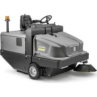
| Product type | Ride-on sweeper with seated operator |
| Brand | Kärcher |
| Model | KM 170600 R D Classic |
| Dimensions (L × W × H) | 2742 × 1904 × 2213 mm |
| Empty weight | 1 695 kg |
| Total permissible weight | 2 701 kg |
| Power supply | 4-stroke diesel engine Kubota V1505 (E4B), 1 498 cm³, 18.5 kW (24.8 PS) at 2 300 rpm |
| Fuel tank capacity | 26 L (diesel) |
| Battery | 12 V, 72 Ah |
| Maximum speed (forward and reverse) | 14 km/h |
| Maximum gradient (direction of travel) | 18 % |
| Maximum lateral gradient | 10 % |
| Sweeping width (without / with 1 / with 2 side brushes) | 1 344 mm / 1 700 mm / 2 000 mm |
| Max. sweeping capacity | 28 000 m²/h (with 2 side brushes) |
| Dust bin volume | 600 L |
| Bin discharge height | 1 540 mm |
| Rotary brush diameter | 400 mm |
| Side brush diameter | 650 mm |
| Filter area (fine dust filter) | 9.1 m² |
| Brakes | Mechanical (front wheels) + hydrostatic (rear wheel) |
| Tire pressure (front and rear) | 8 bar |
| Maintenance | Daily: check levels, tire pressure, filter cleanliness; weekly: clean radiator, check hydraulic oil; maintenance by authorized service center according to operating hours |
| Spare parts and repairability | Original Kärcher parts available; repairs by authorized service center; warranty according to country conditions |
| Safety | Parking brake, seat safety contact, ignition key, rollover protection (slopes), automatic engine stop if driver leaves seat |
| General information | Outdoor use only; do not use in explosive atmosphere or to vacuum flammable liquids; road traffic approval depending on option |
Frequently Asked Questions - KM 170600 R D Classic Kärcher
User questions about KM 170600 R D Classic Kärcher
0 question about this device. Answer the ones you know or ask your own.
Ask a new question about this device
Download the instructions for your Sweeper in PDF format for free! Find your manual KM 170600 R D Classic - Kärcher and take your electronic device back in hand. On this page are published all the documents necessary for the use of your device. KM 170600 R D Classic by Kärcher.
USER MANUAL KM 170600 R D Classic Kärcher
Chairman of the Board of Management

S. Reiser
Director Regulatory Affairs & Certification
71364 Winnenden (Germany)
Tel.: +49 7195 14-0
Fax: +49 7195 14-2212
Winnenden, 2022/02/01
Please read and comply with these original instructions prior
to the initial operation of your appliance and store them for later use or subsequent owners.
Contents
Contents EN 1
Safety instructions EN 1
Symbols in the operating instructions EN 1
Symbols on the machine EN 1
General notes . EN 1
Environmental protection. . . . . EN 2
Warranty. EN 2
Function. EN 2
Proper use. EN 2
Suitable surfaces . EN 2
Operating and Functional Ele
ments. EN 3
Illustration of sweeper.. EN 3
Operating elements . . . EN 3
Before Startup EN 4
Lock/ release parking brake EN 4
Moving sweeper without en
gaging self-propulsion . . EN 4
Moving sweeper by engag
ing self-propulsion . EN 4
Start up EN 4
General notes EN 4
Inspection and maintenance
work EN4
Operation. EN 4
Adjusting driver's seat . . EN 4
Starting the machine . . . EN 4
Drive the machine . EN 5
Sweeping mode . EN 5
Emptying waste container EN 5
Turn off the appliance . . EN 6
Transport EN6
Storage/decommissioning . . . EN 6
Care and maintenance . EN 6
General notes EN 6
Cleaning. EN 6
Maintenance intervals . EN 6
Maintenance Works . . . EN 7
EU Declaration of Conformity. EN 11
Declaration of Conformity. EN 11
Troubleshooting. EN 12
Technical specifications. . EN 13
Safety instructions

Risk of hearing impairment.
Wear ear-protection aids.
Symbols in the operating instructions
△DANGER
Immediate danger that can cause severe injury or even death.
WARNING
Possible hazardous situation that could lead to severe injury or even death.
CAUTION
Possible hazardous situation that could lead to mild injury to persons or damage to property.
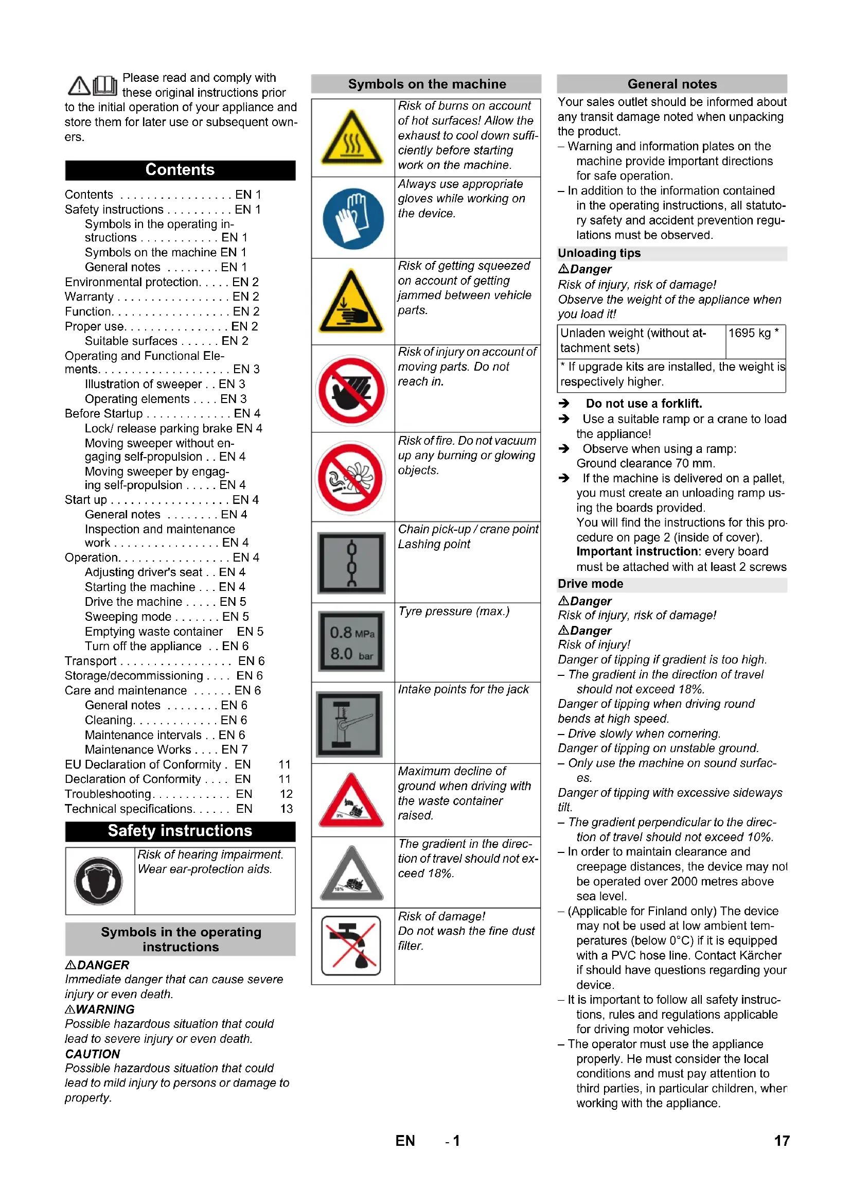
Symbols on the machine
General notes
| Risk of burns on account of hot surfaces! Allow the exhaust to cool down sufficiently before starting work on the machine. | |
| Always use appropriate gloves while working on the device. | |
| Risk of getting squeezed on account of getting jammed between vehicle parts. | |
| Risk of injury on account of moving parts. Do not reach in. | |
| Risk of fire. Do not vacuum up any burning or glowing objects. | |
| Chain pick-up / crane point Lashing point | |
| Tyre pressure (max.) | |
| Intake points for the jack | |
| Maximum decline of ground when driving with the waste container raised. | |
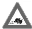
| The gradient in the direction of travel should not exceed 18%. | |
| Risk of damage! Do not wash the fine dust filter. |
Your sales outlet should be informed about any transit damage noted when unpacking the product.
-
Warning and information plates on the machine provide important directions for safe operation.
-
In addition to the information contained in the operating instructions, all statutory safety and accident prevention regulations must be observed.
Unloading tips
Danger
Risk of injury, risk of damage!
Observe the weight of the appliance when you load it!
| Unladen weight (without attachment sets) | 1695 kg * |
| * If upgrade kits are installed, the weight is respectively higher. | |
Do not use a forklift.
Use a suitable ramp or a crane to load the appliance!
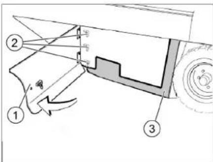
Observe when using a ramp:
Ground clearance 70~mm
If the machine is delivered on a pallet, you must create an unloading ramp using the boards provided.
You will find the instructions for this procedure on page 2 (inside of cover). Important instruction: every board must be attached with at least 2 screws
Drive mode
Danger
Risk of injury, risk of damage!
Danger
Risk of injury!
Danger of tipping if gradient is too high.
The gradient in the direction of travel should not exceed 18% .
Danger of tipping when driving round bends at high speed.
- Drive slowly when cornering.
Danger of tipping on unstable ground.
- Only use the machine on sound surfaces.
Danger of tipping with excessive sideways tilt.
The gradient perpendicular to the direction of travel should not exceed 10% .
In order to maintain clearance and creepage distances, the device may not be operated over 2000 metres above sea level.
- (Applicable for Finland only) The device may not be used at low ambient temperatures (below 0^ ) if it is equipped with a PVC hose line. Contact Kärcher if should have questions regarding your device.
- It is important to follow all safety instructions, rules and regulations applicable for driving motor vehicles.
- The operator must use the appliance properly. He must consider the local conditions and must pay attention to third parties, in particular children, when working with the appliance.
- The appliance may only be used by persons who have been instructed in handling the appliance or have proven qualification and expertise in operating the appliance or have been explicitly assigned the task of handling the appliance.
- The appliance must not be operated by children, young persons or persons who have not been instructed accordingly.
- It is strictly prohibited to take co-passengers.
- Ride-on appliances may only be started after the operator has occupied the driver's seat.
Please remove the ignition key, when not in use, to avoid unauthorised use of the appliance.
Never leave the machine unattended so long as the engine is running. The operator may leave the appliance only when the engine has come to a standstill, the appliance has been protected against accidental movement, if necessary, by applying the immobilization brake and the ignition key has been removed.
Appliances with combustion engine
Danger
Risk of injury!
- Do not close the exhaust.
- Do not bend over the exhaust or touch it (risk of burns).
- Do not touch the drive motor (risk of burns).
- Exhaust gases are poisonous and hazardous to health, do not inhale them.
- The engine requires approx. 3-4 seconds to come to a standstill once it has been switched off. During this time, stay well clear of the working area.
Machines with driver cabin
- In emergencies, destroy the windows with a hammer.
NOTICE
The emergency hammer is located in the foot area, underneath the driver seat.
Accessories and Spare Parts
- Only use accessories and spare parts which have been approved by the manufacturer. The exclusive use of original accessories and original spare parts ensures that the appliance can be operated safely and trouble free.
- For additional information about spare parts, please go to the Service section at www.kaercher.com.
Environmental protection
| The packaging material can be recycled. Please do not throw the packaging material into household waste; please send it for recycling. | |
| Old appliances contain valuable materials that can be recycled; these should be sent for recycling. Batteries, oil, and similar substances must not enter the environment. Please dispose of your old appliances using appropriate collection systems. |
Notes about the ingredients (REACH)
You will find current information about the ingredients at:
www.kaercher.com/REACH
Warranty
The warranty terms published by the relevant sales company are applicable in each country. We will repair potential failures of your appliance within the warranty period free of charge, provided that such failure is caused by faulty material or defects in manufacturing. In the event of a warranty claim please contact your dealer or the nearest authorized Customer Service center. Please submit the proof of purchase.
Function
The sweeper operates using the sweepshovel principle.
- The rotating roller brush moves the dirt directly into the waste container.
- The side brush cleans the corners and edges of the surface and moves dirt and debris into the path of the roller brush.
- The fine dust is sucked in via the dust filter through the suction blower.
Proper use
Use this sweeper only as directed in these operating instructions.
The machine with working equipment must be checked to ensure that it is in proper working order and is operating safely prior to use. Otherwise, the appliance must not be used.
- This sweeper has been designed to sweep dirt and debris from outdoor surfaces.
- The appliance should not be used in closed rooms.
- Ride-on machines that are not equipped with the proper equipment (option ex factory) are not approved for public transport.
- The appliance can be used on public roads only after an individual acceptance by an official regulatory body.
- All device hoods may only be opened in water-protected areas.
- The machine is not suitable for vacuuming dust which endangers health.
- The machine may not be modified.
- Never vacuum up explosive liquids, combustible gases or undiluted acids and solvents. This includes petrol, paint thinner or heating oil which can generate explosive fumes or mixtures upon contact with the suction air. Acetone, undiluted acids and solvents must also be avoided as they can harm the materials on the machine.
- Do not sweep/vacuum up any burning or glowing objects.
- The machine is only suitable for use on the types of surfaces specified in the operating instructions.
- The machine may only be operated on the surfaces approved by the company or its authorised representatives.
- The machine may not be used or stored in hazardous areas. It is not allowed to use the appliance in hazardous locations.
- The following applies in general: Keep highly-flammable substances away from the appliance (danger of explosion/fire).
Suitable surfaces
△DANGER
Risk of injury! Verify the stability of the ground prior to driving on it.
Asphalt
-Industrial floor
- Sreed
Concrete
- Paving stones
CAUTION
Risk of damage! Do not sweep up straps, strings or wires as these may wrap around the brush roller.
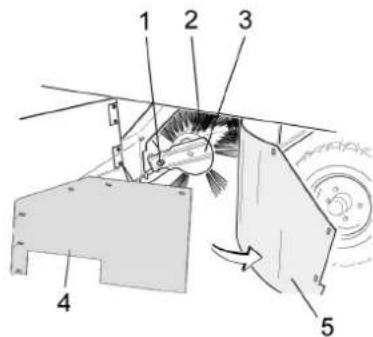
Operating and Functional Elements
A
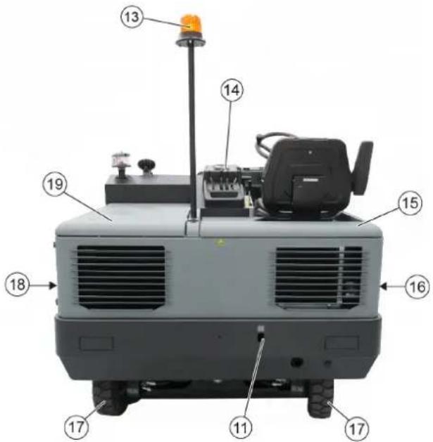
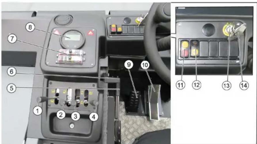
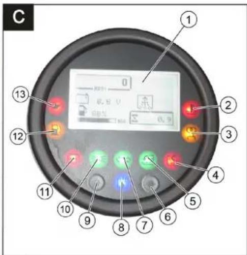
Illustration of sweeper Operating elements
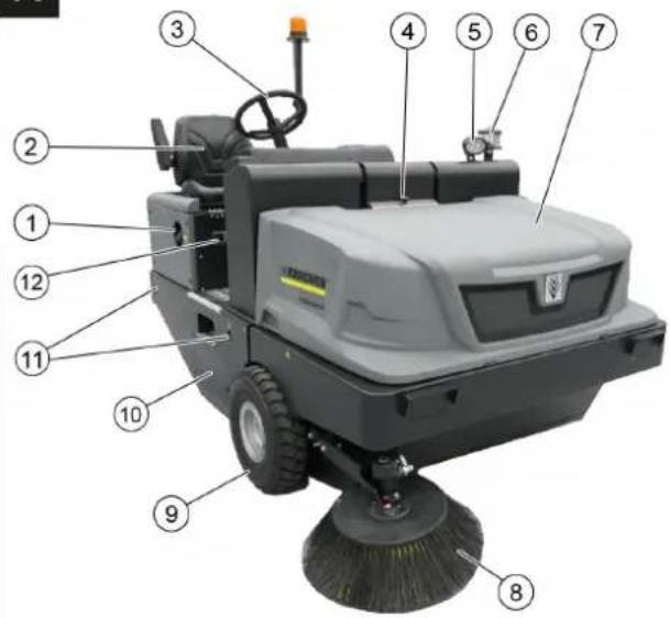
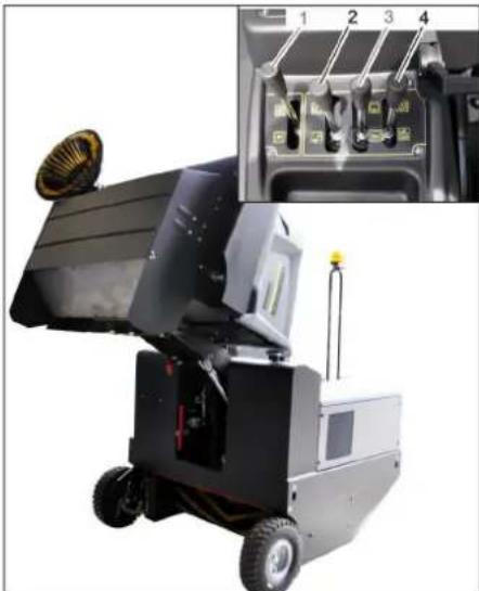
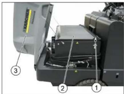
Illustration A
1 Reservoir cover
2 Seat (with seat contact switch)
3 Steering wheel
4 Lock of appliance hood
5 Blue Spot (optional)
6 Centrifugal separator
7 Cover
8 Side brush, right
9 Front wheel
10 Roller brush access
11 Lashing point
12 Nameplate
13 Beacon lamp
14 Control elements
15 Appliance cover right side
16 Cover, right
17 Drive wheel
18 Cover, left
19 Bonnet left side (engine bonnet)
Illustration 3
1 Roller brush control lever On/Off
2 Control lever waste container raise / lower
3 Control lever side brush raise / lower
4 Control lever container flap open/close
5 Parking brake
6 Motor speed adjustment Gas lever
7 Fuses
8 Indicator lamps and display
9 Brake pedal
10 Accelerator pedal forward / reverse
11 Switch blower and filter cleaning Position centred: Filter cleaning and blower off Front position: Blower on Rear position: Filter cleaning On
12 Horn switch
13 Ignition lock Position 0: Switch off engine Position 1: Ignition on Position 2: Start the engine
14 Key for roller brush access
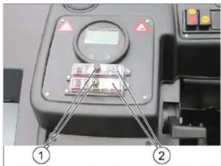
Indicator lamps and display
Illustration
1 Display
Motor speed
Filter cleaning active
Battery capacity
Operating hour counter
Tank indicator
2 Cooling water temperature warning lamp
3 Preglow indicator light
4 Indicator light for closed waste container-flap
5 Warning light for open waste container flap
6 not assigned
7 Indicator lamp for direction indicator not assigned
8 Suction fan display on
9 not assigned
10 Working light indicator light not assigned
11 Battery control lamp
12 Warning lamp fuel reserve
13 Oil pressure warning lamp
Before Startup
Lock/ release parking brake
Loosen parking brake; press brake pedal at the same time.
Activate the parking brake; press brake pedal at the same time.
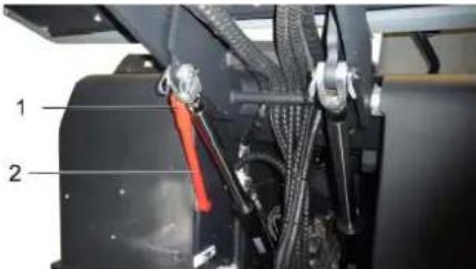
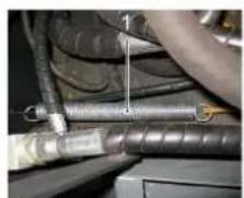
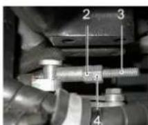
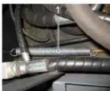
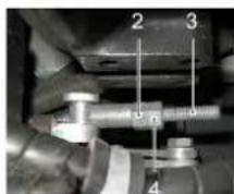
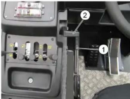
Moving sweeper without engaging self-propulsion
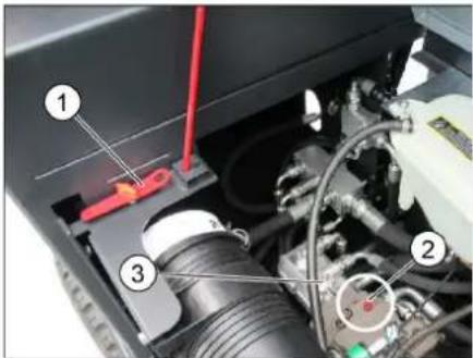
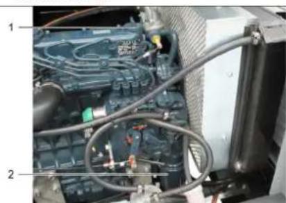
1 Special tool
2 Screw for freewheeling
3 Hydraulic pump
Open engine cover.
Turn the screw for freewheel (red) of the hydraulic pump by 180^ (anti-clockwise).
Use special tools.
NOTICE
The special tool (red screwdriver) is located in a holder in the vehicle frame, next to the freewheel.
CAUTION
Do not move the machine for long distances without engaging self-propulsion; a speed of 10km / h should not be exceeded.
Turn back the freewheel of the hydraulic pump in a clockwise direction up to the stop after moving the machine.
Moving sweeper by engaging selfpropulsion
Turn back the freewheel of the hydraulic pump in a clockwise direction up to the stop after moving the machine. Use special tools.
Start up
General notes
Read the operating instructions of the engine manufacturer before start-up and follow the safety instructions carefully.
Park the sweeper on an even surface.
Remove ignition key.
Lockparkingbrake.
Inspection and maintenance work
Daily before starting operations
Check fill level of fuel tank.
Check engine oil level.
Check cooler water level.
Check tyre pressure.
Check the sweeping roller and the side brush for wear and wrapped belts.
Check the wheels for tied up belts.
Check the centrifugal separator and the air filter, clean if required.
Check function of all operator control elements.
Check appliance for damages.
Clean the dust filter with the filter cleaning button.
Note: For description, see section on Care and maintenance.
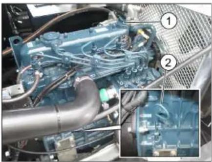
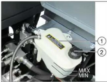
Frost protection
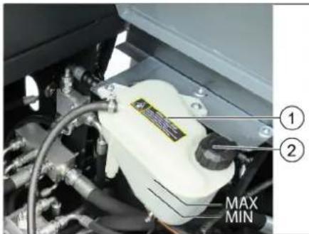
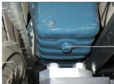
1 Coolant expansion tank
2 Closing head
If frost is expected, check whether there is enough anti-frosting agent in the cooling water.
Refuelling
△Danger
Risk of explosion!
- Only use the fuels specified in the Operations Manual.
- Do not refuel the machine in enclosed spaces.
Smoking and naked flames are strictly prohibited.
- Ensure that no fuel reaches the hot open surfaces.
Switch off engine.
Open the tank lock.
Fill in diesel. Below exterior temperatures of 6^, only Winter diesel must be used, as there might be problems with operating due to the flocking of diesel components.
Wipe off any spilt fuel and close fuel filler cap.
Close the tank door.
Operation
Adjusting driver's seat
Pull seat adjustment lever outwards.
Slide seat, release lever and lock in place.
Check that the seat is properly locked position by attempting to move it backwards and forwards.
Starting the machine
ATTENTION
Ensure that the brushes are raised up.
All four control levers must be in middle position.
Do not press the accelerator pedal when starting up!
The machine is equipped with a seat contact switch If the driver's seat is vacated, the machine is switched off.
The fine dust filter is automatically cleaned when the ignition is switched on.
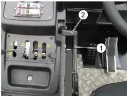
1 Parking brake
2 Motor speed adjustment Gas lever
Sit on the driver's seat.
Activate parking brake.
Set motor speed to approx. 75% of the maximum speed.
Insert the ignition key into the ignition switch.
Turn the ignition key to ignition on (position I). Diesel motor: The preglow indicator light lights up.
If the preglow indicator light goes out, turn the ignition key to Position II (Start motor) and hold it until the motor has started (max. 10 seconds).
Release the ignition key. The ignition key turns to position I.
At ambient temperatures below 0^ : A low the motor to warm up at a low motor speed before beginning work.
Note
If the motor does not start, repeat the startup process.
Drive the machine
DANGER
Risk of accident!
It is prohibited to drive with the waste container raised!
CAUTION
Risk of damage!
Let the motor warm up sufficiently prior to driving or loading the vehicle.
Always press the accelerator pedal carefully and slowly. Do not jerkily change from reverse to forward drive or vice versa.
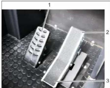
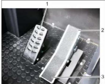
1 Brake pedal
2 Accelerator pedal, "forwards"
3 Accelerator pedal, "reverse"
Push the motor speed adjustment all the way to the front (operating speed).
Press brake pedal and keep it depressed.
Release parking brake.
Press accelerator pedal down slowly.
Control the driving direction with the steering wheel.
Drive forward
Press slowly the accelerator pedal "forward".
Reverse drive
△DANGER
Risk of injury!
When reversing, there must not be any risk for third parties, have somebody marshal the driver if necessary.
Press slowly the accelerator pedal "reverse".
Driving method
The accelerator pedal can be used to vary the driving speed infinitely.
Avoid sudden operation of the pedal as this may damage the hydraulic system.
In the event of power loss on inclined surfaces, slightly reduce the pressure on the accelerator pedal.
Braking / stopping
Release the drive pedal, the machine brakes automatically and stops.
For a stronger braking effect or in case of an emergency, actuate the brake pedal.
Driving over obstacles
ATTENTION
Objects or loose obstacles may not be run over or pushed. Driving over fixed obstacles which are more than 70~mm high:
Stationary obstacles may be driven over only when a suitable ramp is used. Driving over fixed obstacles which are 70 mm high or less:
Drive forwards slowly and carefully.
Sweeping mode
CAUTION
Do not sweep up packing strips, wire or similar objects as this may damage the sweeping mechanism.
Note: To achieve an optimum cleaning result, the driving speed should be adjusted to take specific situations into account. Note: The fine dust filter is automatically cleaned every 10 minutes.
Note: When working frequently in the fine dust area, the filter must be cleaned more often. This means manually cleaning the fine dust filter from time to time.
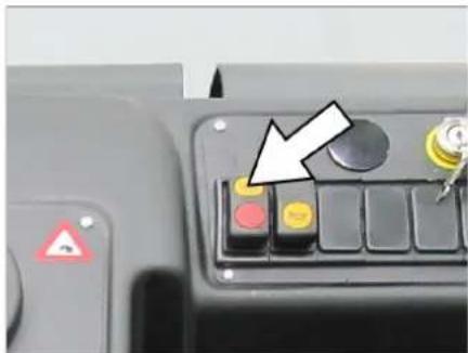
Cleaning the fine dust filter manually
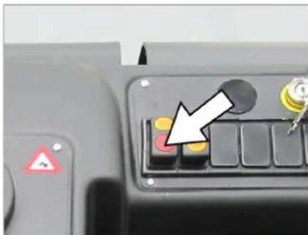
Clean the fine dust filter with the filter cleaning button.
Control lever
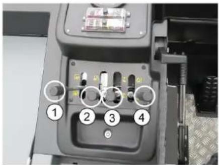
1 Switch on and lower roller brush (to the front)/switch off and raise (to the rear)
2 Lower the waste container (to the front)/ raise (to the rear)
3 Lower side brushes (to the front)/raise (to the rear)
4 Open container flap (to the front)/close (to the rear)
Sweeping dry floors
Switch on the blower.
Control lever container flap (4) to the front: Container flap opens. Note: The green indicator lamp must light up.
With surface cleaning: Roller brush control lever (1) forwards: Roller brush switches on and lowers them.
With cleaning of side edges: Control lever side brush (3) to the front: Side brush is lowered.
Sweeping damp or wet floors
Switch off the blower.
Control lever container flap (4) to the front: Container flap opens. Note: The green indicator lamp must light up.
With surface cleaning: Roller brush control lever (1) forwards: Roller brush switches on and lowers them.
With cleaning of side edges: Control lever side brush (3) to the front: Side brush is lowered.
Emptying waste container
△DANGER
Risk of injury!
During the emptying process, persons and animals must not stay within the swivelling range of the waste container.
△DANGER
Risk of crushing!
Never reach into the rod assembly for the drainage mechanism. Do not stay under the raised container.
△DANGER
Danger of tipping!
Place the device on an even surface during the emptying process.
ATTENTION
Risk of personal injury or damage!
Stones may be catapulted off by the rotating roller brush during the emptying process.
Raise the roller brush and side brush by means of the control levers, in order to do so, pull the control levers (1 and 3) to the back.
Close the container flap, in order to do so, move the control lever (4) to the back:
Note: The red indicator lamp must light up.
Raise the container flap, in order to do so, move the waste container control lever (2) to the back:
Slowly drive towards the collection container.
Lockparking brake.
Open the container flap, in order to do so, push the container flap operating lever (4) to the front and empty the waste container.
Note: The green indicator lamp must light up.
Close the container flap, in order to do so, push the container flap operating lever (4) to the back until it is tipped inwards in the end position.
Note: The red indicator lamp must light up.
Release parking brake.
Drive away the collection container slowly.
Lower the waste container into the end position, in order to do so, move the waste container control lever (2) to the front
Turn off the appliance
Raise the roller brush and side brush by means of the control levers, in order to do so, pull the control levers (1 and 3) to the back.
Close the container flap, in order to do so, move the control lever (4) to the back:
Pull the motor speed adjustment all the way to the back.
Press brake pedal and keep it depressed.
Lockparkingbrake.
Turn ignition key to "0" and remove it.
Transport
△DANGER
Risk of injury and damage! Observe the weight of the appliance when you transport it.
Turn ignition key to "0" and remove it.
Lockparkingbrake.
Secure the appliance at the lashing points (4x) using tension belts, ropes or chains.
Secure the wheels of the machine with wheel chocks.
When transporting in vehicles, secure the appliance according to the guidelines from slipping and tipping over.
Storage/decommissioning
△DANGER
Risk of personal injury or damage!
Consider the weight of the appliance when storing it.
Park the device on a level surface in a dry, frost protected area. Protect it against dust by means of covering material.
Raise the roller brush and the sidebrushes to prevent the bristles from being damaged.
Turn ignition key to "0" and remove it.
Lockparking brake.
Lock the sweeper to ensure that it does not roll off.
Drain off the cooling water if frost is expected and check whether there is adequate anti-frosting agent.
If the vehicle is not used for a longer period of time, observe the following points:
Clean the inside and outside of the vehicle.
Change engine oil.
Disconnect the negative terminal of the battery if the appliances is not used for more than 4 weeks.
Charge battery approx. every 2 months.
Cover the battery and protect it from short circuit.
Care and maintenance
General notes
CAUTION
Risk of damage!
Do not wash the fine dust filter.
All device hoods may only be opened in water-protected areas.
Maintenance work may only be carried out by approved customer service outlets or experts in this field who are familiar with the respective safety regulations.
Mobile appliances used for commercial purposes are subject to safety inspections according to VDE 0701.
Park the sweeper on an even surface.
Turn ignition key to "0" and remove it.
Lockparkingbrake.
Cleaning
CAUTION
Risk of damage! Do not clean the appliance with a water hose or high-pressure water jet (danger of short circuits or other damage).
Cleaning the inside of the machine
Danger
Risk of injury! Wear dust mask and protective goggles.
Clean machine with a cloth.
Blow through machine with compressed air.
External cleaning of the appliance
Clean the machine with a damp cloth which has been soaked in mild detergent.
Note: Do not use aggressive cleaning agents.
Maintenance intervals
Note: The elapsed-time counter shows the timing of the maintenance intervals.
Maintenance by the customer
Note: Where maintenance is carried out by the customer, all service and maintenance work must be undertaken by a qualified specialist. If required, a specialised Kärcher dealer may be contacted at any time.
Daily maintenance:
Check fill level of fuel tank.
Check engine oil level.
Check cooler water level.
Check tyre pressure.
Check the sweeping roller and the side brush for wear and wrapped belts.
Check the wheels for tied up belts.
Check the centrifugal separator and the air filter, clean if required.
Check function of all operator control elements.
Check appliance for damages.
Clean the dust filter with the filter cleaning button.
Weekly maintenance:
Check fuel filter.
Clean the water cooler.
Clean the hydraulic oil cooler.
Check hydraulic unit.
Check the hydraulic oil level.
Check brake fluid status.
Check the pad for wear, replace if required.
Check the container lid and lubricate it. Maintenance following wear:
Replace sealing strips.
Readjust the side seals or replace them.
Replace roller brush.
Replace side brush.
Note: For description, see section on Maintenance work.
Maintenance by Customer Service
Maintenance to be carried out after 50 operating hours:
Have the first maintenance performed by the customer service in accordance with the inspection check list.
Maintenance after 250/500/1000/1500/ 2000 operating hours:
Have the maintenance performed by the customer service in accordance with the inspection check list.
Note: In order to safeguard warranty claims, all service and maintenance work during the warranty period must be carried out by the authorised Kärcher Customer Service in accordance with the maintenance booklet.
Maintenance Works
Preparation:
Park the sweeper on an even surface.
Turn ignition key to "0" and remove it.
Lockparking brake.
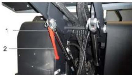
General notes on safety DANGER
Risk of injury! Always apply the safety bar when the waste container is raised.
1 Holder of safety rod
2 Safety rod
Fold the safety rod for the high emptying up and insert it into the holder (se-cured).
Safety notes regarding the batteries Please observe the following warning n when handling batteries:
| Observe the directions on the battery, in the instructions for use and in the vehicle operat-ing instructions! |
| Wear an eye shield! |
| Keep away children from acid and batteries! |
| Risk of explosion! |
| Fire, sparks, open light, and smoking not allowed! |
| Danger of causticization! |
| First aid! |
| Warning note! |
| Disposal! |
| Do not throw the battery in the dustbin! |
Danger
Risk of explosion! Do not put tools or similar on the battery, i.e. on the terminal poles and cell connectors.
Danger
Risk of injury! Ensure that wounds never come into contact with lead. Always clean your hands after having worked with batteries.
△DANGER
Risk of fire and explosion!
Smoking and naked flames are strictly prohibited.
Rooms where batteries are charged must have good ventilation because highly explosive gas is emitted during charging.
Danger
Danger of causticization!
Rinse thoroughly with lots of clear water if acid gets into the eye or comes in contact with the skin.
- Then consult a doctor immediately.
- Wash off the acid If it comes in contact with the clothes.
Installing and connecting the battery
Insert battery in battery mount.
Screw on mounts on battery base.
Connect pole terminal (red cable) to positive pole (+).
Connect pole terminal to negative pole (-).
Note: Check that the battery pole and pole terminals are adequately protected with pole grease.
Check fluid level in the battery and adjust if required
CAUTION
Regularly check the fluid level in acid-filled batteries.
The acid in a fully charged battery has a specific weight of 1.28kg / l at a temperature of 20^ .
The acid in a partially discharged battery has a specific weight between 1.00 and 1.28kg / l
- The specific weight of the acid must be uniform in all cells.
Unscrew all cell caps.
Take a sample from each cell using the acid tester.
Puthe acid sample back into the same cell.
Where fluid level is too low, top up cells to the mark provided with distilled water.
Charge battery.
Screw in cell caps.
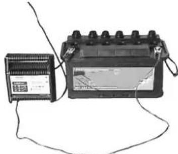
Charging battery
Danger
Risk of injury! Comply with safety regulations on the handling of batteries. Observe the directions provided by the manufacturer of the charger.
Danger
Charge the battery only with an appropriate charger.
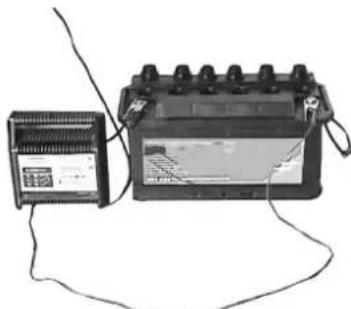
Unscrew all cell caps.
Connect positive terminal cable from the charger to the positive pole connection on the battery.
Connect negative terminal cable from the charger to the negative pole connection on the battery.
Plug in mains connector and switch on charger.
Charge battery using lowest possible level of charging current.
Note: When the battery is charged, first remove the charger from the mains and then disconnect it from the battery.
Remove the battery
Disconnect pole terminal to negative pole (-).
Disconnect pole terminal to positive pole (+)
Loosen the mounts on battery base.
Remove the battery from the battery holder.
Dispose of the used battery according to the local provisions.
Check engine oil level and top up, if required
Danger
Risk of burns!
Allow engine to cool down.
Wait for at least 5 minutes after switching off the engine before checking the engine oil fill level.
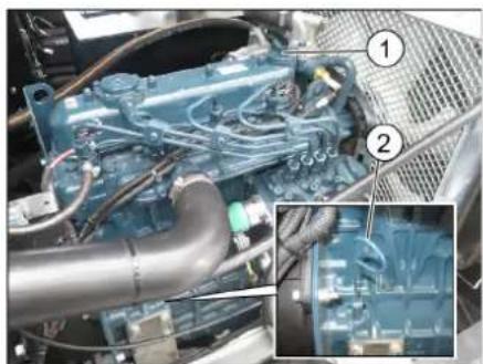
1 Screw cap, oil fill opening
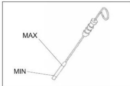
2 Oil dipstick
Pull out oil dipstick.
Wipe off oil dipstick and insert.
Pull out oil dipstick.
Read the value of the oil level.
Insert the oil dip again.
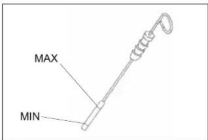
- The oil level must lie between "MIN" and "MAX" marking.
- Add motor oil if the oil level is below the "MIN" marking.
- Do not fill oil above the "MAX" marking.
Loosen the screw cap of the oil filling opening.
Fill in motor oil. Oil grade: see Technical Data
Close oil filler opening.
Wait at least 5 minutes.
Check engine oil level.
Change the motor oil and the oil filter WARNING
Risk of burns!
To change the motor oil and motor oil filter, allow the vehicle to cool down until there is no longer a risk of burns.
Note
A warm motor facilitates the draining of the motor oil.
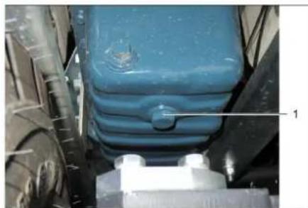
1 Oil drain screw
Prepare a collection container for at least 10 litres of oil.
Switch off engine.
Remove oil cap.
Unscrew oil drain plug.
Drain off oil.
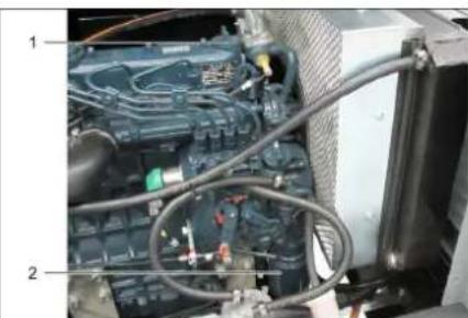
1 Oil filler cap
2 Engine oil filter
Unscrew the oil filter.
Clean the intake and sealing areas.
Coat the washer of the new oil filter with oil before fitting it.
Fit in the new oil filter and tighten it by hand.
Screw in the oil drain plug with the new seal.
Tightening torque: Nm
Fill in motor oil. For oil type and filling quantity refer to Chapter "Technical specifications".
Close oil cap.
Let the motor run for approx. 30 seconds.
Wiat least 5 minutes.
Check engine oil level.
Check for leaks.
Deliver the old oil to the respective collection centres.
Cleaning and replacing the air filter
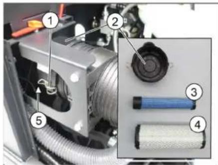
1 Locking
2 Air filter housing
3 Safety cartridge
4 Filter cartridge
5 Blowout opening pointing downwards
Open the lock.
Remove the air filter housing.
Remove the filter cartridge.
Clean the interior of the air filter reservoir.
Only remove the safety cartridge if it is being replaced.
Clean the filter insert: Tap out the dust on a hard surface, blow out from inside to outside with compressed air at max. 30 psi (2 bar).
The seal face and filter insert must be clean and free of damage upon installation.
Insert the cleaned filter insert. Important: A severely contaminated or damaged filter insert must be replaced.
If the filter insert is being replaced, replace the safety cartridge too. Important: No dust is allowed to enter through the suction opening when replacing the filter insert and safety cartridge
Note: Installation position with blowout opening pointing down (see illustration).
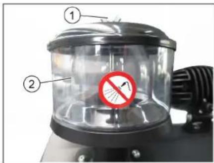
1 Wing nut
2 Centrifugal separator
Unscrew the wing nut from the centrifugal separator.
Clean the centrifugal separator.
Check hydraulic oil level and refill hydraulic oil
NOTICE
The waste container must not be raised.
Open engine cover.

1 Hydraulic oil sight glass
2 Manometer
3 Screw cap, oil fill opening
Check hydraulic oil level in the looking glass.
The oil level must lie between "MIN" and "MAX" marking.
- Add hydraulic oil if the oil level is below the "MIN" marking.
Loosen the closing cap of the oil filling opening.
Clean the filling area.
Refill hydraulic oil.
Oil grade: see Technical Data
Replace and tighten the closing cap of the oil filling opening.
NOTICE
If the pressure gauge shows an increased hydraulic oil pressure, the hydraulic oil filter must be replaced by Karcher customer service.
Check hydraulic unit
NOTICE
Only Kärcher Customer Service is authorised to carry out maintenance tasks on the hydraulic unit.
Lockparkingbrake.
Start the motor.
Check all hydraulic hoses and connections and ensure that they are leak-proof.
Check water cooler and maintain it △Danger
Danger of scalding by boiling water! Let the cooler cool down for at least 20 minutes.
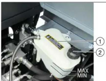
1 Coolant expansion tank
2 Closing head
Check the cooling water level on the balance reservoir (water level between MIN and MAX).
Clean cooler lamella.
Check cooler hoses and connections and ensure that they are leak-proof.
Checking roller brush
Start the motor.
Raise the waste container up to the end-position.
Switch off engine.
Lockparkingbrake.
Use the safety bar for emptying from a height.
Remove belts or cords from roller brush.
Remove the safety bar.
Start the motor.
Lower the waste container up to the end-position.
Switch off engine.
Replacing roller brush
With the waste container lowered.
1 Side panel, right
2 Wing nut
3 S i d e s e a l
Open right side panel with key.
Unscrew the wingnuts from the holding plate side seals and remove the holding plate.
1 Fastening screws of the roller brush intake
2 Roller brush
3 Roller brush intake
4 Holding plate for side seal
5 S i d e s e a l
Flip the side seal out.
Uncscrew the retaining screw of the roller brush intake, and swing the intake to the outside.
Pull out roller brush.
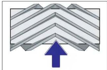
Installation position of roller brush in direction of travel (top view)
Note: When installing the new roller brush, ensure correct positioning of the bristle assembly.
Install new roller brush. The nuts of the roller brush must be inserted on the notches of the opposite crank.
Note: Once the new roller brush has been installed, the sweeping track must readjusted.
Check and adjust roller brush sweeping track
Check tyre pressure.
Switch off suction blower.
Drive sweeper on to a smooth, even surface covered with a visible layer of dust or chalk.
Lower the roller brush by means of the control lever and let it run (approx. 10 s).
Raise roller brush.
Drive machine backwards.
Check sweeping mirror.
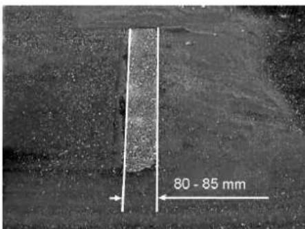
The sweeping track should have an even rectangular shape which is 80 - 85mm wide. Adjusting the sweeping level
1 Sprin g
2 Rating nut
3 L o c k n u t
4 Threaded rod
Adjust the sweeping track position by adjusting the adjustment screw.
Check sweeping mirror.
Check and adjust sweeping track of the side-brush
Check tyre pressure.
Raise the roller brush and side brushes using the control levers.
Drive sweeper on to a smooth, even surface covered with a visible layer of dust or chalk.
Control lever side brush (3) to the front: Side brush is lowered.
Allow the side brushes to run for approx. 10 seconds.
The side-brushes lift up.
Drive machine backwards.
Check sweeping mirror.
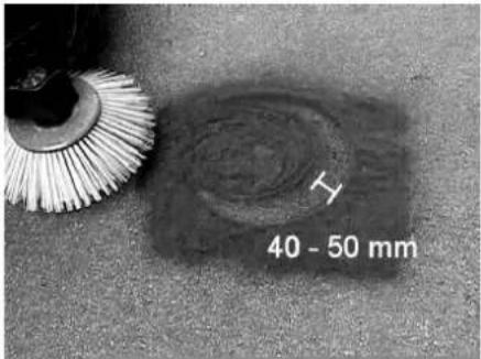
The width of the sweeping track should lie between 40-50 mm.

Set the sweeping track using the two adjusting screws.
Check sweeping mirror.
Adjust the side seals
Check tyre pressure.
Drive the waste container up and secure it with the safety rod.
DANGER
Risk of injury! Always apply the safety bar when the waste container is raised.
Fold the safety rod for the high emptying up and insert it into the holder (se-cured).
1 Holder of safety rod
2 Safety rod
Open the side cover as described in Chapter "Replace brush roller".
Release the 6 wing nuts on the side holding plate.
Loosen 3 nuts (SW 13) on the front holding plate.
Press the side seal down (elongated hole) until it is about 1 to 3mm to the floor.
Screw in the holding plates.
Repeat the procedure on the other side of the appliance.
Check the tyre pressure
Park the sweeper on an even surface.
Connect air pressure testing device to tyre valve.
Check air pressure and adjust if required.
For permissible tyre air pressures see "Technical data".
Checking/changing the fine dust filter WARNING
Risk of injury!
Wear a dust mask when working around the dust filter. Observe safety regulations on the handling of fine particles.
Clean the fine dust filter with the filter cleaning button.
Empty waste container.
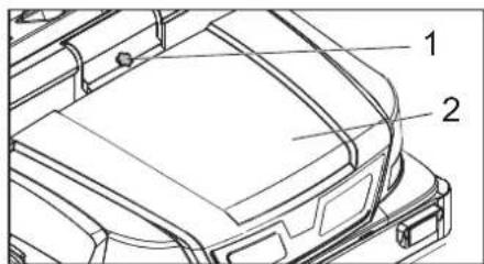
1 Lock of appliance hood
2 C o v e r
Open the lock, remove the star grip screw to do this.
Fold cover forwards.
1 Lock, filter cover (2x)
2 Filter cover
3 Cover
Opn filter cap.
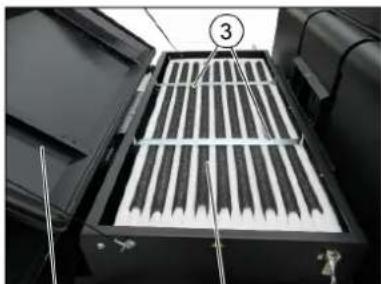
② ①
1 Fine dust filter
2 Filter cover
3 Cross struts
Open filter cap.
Check the fine dust filter, clean or replace if necessary.
Note
Exchanging the fine dust filter may only be done by Karcher Customer Service.
Insert and lock the filter cover.
Check and adjust the V-Belt
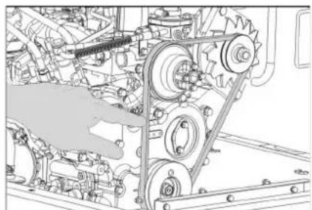
The V-Belt must deflect approx. 7-9 mm at a pressure of 10kg
Get the V-belt tension adjusted by an authorized customer service.
Replacing fuses
1 Lock n u t
2 Cover fuse box
Unscrew the knurled nut.
Open the cover on the fuse box.
Check the fuses.
Replace defective fuses.
Note: Only use fuses with identical safety ratings.
Check the fuses.
| FU 01 Ignition 10 A |
| FU 02 Pre-heat 5 A |
| FU 03 Multifunction display 5 A |
| FU 04 Vibrator system 20 A |
| FU 05 Reverse warning system and flap indicator |
| FU 06 Cabin lighting Windshield wiper (option) |
| FU 07 Lights Blinker (option) |
| FU 08 Lights Blue Spot (option) |
| FU 09 Rear position lights (op-tion) |
| FU 10 Dipped beam (option) 10 A |
| FU 11 Front position lights (op-tion) |
| FU 12 Hydraulic cooler 25 A |
| FU 13 Main fuse 60 A |
| FU 15 Spark plugs 70 A |
| FU 20 Fan (option) 20 A |
| FU 21 Fan cabin (option) 25 A |
| FU 22 Compressor (option) 7,5 A |
Replace defective fuses.
Note: Only use fuses with identical safety ratings.
EU Declaration of Conformity
We hereby declare that the machine described below complies with the relevant basic safety and health requirements of the EU Directives, both in its basic design and construction as well as in the version put into circulation by us. This declaration shall cease to be valid if the machine is modified without our prior approval.
Product: Ride-on vacuum sweeper
Type: 1.186-145.0
Relevant EU Directives
2006/42/EC (+2009/127/EC)
2014/30/EU
2000/14/EC
Applied harmonized standards
EN 60335-1
EN 60335-2-72
EN 55012: 2007 + A1: 2009
EN 61000-6-2: 2005
EN 62233: 2008
Applied national standards
Applied conformity evaluation method
2000/14/EC: Appendix V
Sound power level dB(A)
Measured: 100
Guaranteed: 103
The signatories act on behalf of and with of the authority of the company management.

Chairman of the Board of Management
S. Reiser
Director Regulatory Affairs & Certification
Documentation supervisor:
S. Reiser
Alfred Kärcher SE & Co. KG
71364 Winnenden (Germany)
Tel.: +49 7195 14-0
Fax: +49 7195 14-2212
Winnenden, 2022/02/01
Declaration of Conformity
We hereby declare that the product described below complies with the relevant provisions of the following UK Regulations, both in its basic design and construction as well as in the version put into circulation by us. This declaration shall cease to be valid if the product is modified without our prior approval.
Product: Ride-on vacuum sweeper
Type: 1.186-145.0
Currently applicable UK Regulations
S.I. 2008/1597 (as amended)
S.I. 2016/1091 (as amended)
S.I. 2001/1701 (as amended)
Designated standards used
EN 60335-1
EN 60335-2-72
EN 55012: 2007 + A1: 2009
EN 61000-6-2: 2005
EN 62233: 2008
Applied national standards
Applied conformity assessment procedure
S.I. 2001/1701 (as amended): Schedule 8
Sound power level dB(A)
Measured: 100
Guaranteed: 103
The signatories act on behalf of and with of the authority of the company management.
H.Jenner
Chairman of the Board of Management
S. Reiser
Director Regulatory Affairs & Certification
Documentation supervisor:
S. Reiser
Alfred Kärcher SE & Co. KG
71364 Winnenden (Germany)
Tel.: +49 7195 14-0
Fax: +49 7195 14-2212
Winnenden, 2022/02/01
| Troubleshooting | |
| Fault Remedy | |
| Appliance cannot be started | Sit on the driver seat, the seat contact switch gets activated. |
| Charging or replacing battery | |
| Fill in fuel,deaerate the fuel system | |
| Change fuel filterReplace fuel prefilter | |
| Check fuel pipes,connections and joints and maintain them if required | |
| Inform Kärcher Customer Service. | |
| Engine is running erratically | Clean air filter or change filter cartridge. |
| Check fuel pipes,connections and joints and maintain them if required | |
| Inform Kärcher Customer Service. | |
| Engine is overheated Refill coolant | |
| Rinse cooler | |
| Tighten V-Belt | |
| Inform Kärcher Customer Service. | |
| Engine is running but machine is only moving slowly or is not moving at all | Release parking brake |
| Check for trapped ribbons and strings. | |
| Inform Kärcher Customer Service. | |
| Whistling sound in the hydraulic system | Refill hydraulic fluid |
| Inform Kärcher Customer Service. | |
| Brushes are rotating slowly or not at all | Move the gas lever all the way to the front (high speed). |
| Check for trapped ribbons and strings. | |
| Inform Kärcher Customer Service. | |
| Too little or no suction power in the brush area | Clean filter |
| Inform Kärcher Customer Service. | |
| Dust gathers in the machine Adjust | the side seals |
| Switch on blower | |
| Clean dust filter | |
| Replace filter washers | |
| Inform Kärcher Customer Service. | |
| Sweeping unit does not pick up waste | Empty waste container |
| Close the waste container completely. | |
| Clean dust filter | |
| Replacing roller brush | |
| Adjust sweeping track | |
| Replace sealing strips of the waste container | |
| Remove the blocking of the brush roller | |
| Inform Kärcher Customer Service. | |
| Waste container does not raise or lower | Remove the locking support from the waste container |
| Inform Kärcher Customer Service. | |
| Waste container is rotating slowly or not at all | Inform Kärcher Customer Service. |
| Operation problems with hydraulic movement parts | Inform Kärcher Customer Service. |
Technical specifications
| KM 170/600 R D Classic | ||
| Machine data | ||
| Drive speed, forward km/h 14 | ||
| Drive speed, reverse km/h 14 | ||
| Climbing capability (max.) -- 18% | ||
| Surface cleaning performance without side brushes m | 2/h 18800 | |
| Surface cleaning performance with 1 side brushes m | 2/h 23800 | |
| Surface cleaning performance with 2 side brushes m | 2/h 28000 | |
| Working width without side brushes mm 1344 | ||
| Working width with 1 side brushes mm 1700 | ||
| Working width with 2 side brushes mm 2000 | ||
| Protection type, drip-proof -- IPX 3 | ||
| Usage duration when tank is full h 4,5 | ||
| Engine | ||
| Type | -- Kubota | V1505 (E4B) |
| Type | -- 4-cylinder 4-stroke diesel engine | |
| CO2Emission according to the measurement procedure of EU regulation 2016/1628 (level V) | g/kWh | 1018,0 |
| Cooling type | -- Water cooling | |
| Rotation direction | -- Anticlockwise direction | |
| Cylinder capacity | cm³ | 1498 |
| Max. power | kW/PS | 18,5/24,82300 1/min |
| Battery | V, Ah | 12, 72 |
| Fuel | ||
| Engine oil volume | I | 6 |
| Engine oil type | >25 °C | SAE30, SAE10W-30, SAE15W-40 |
| 0 - 25 °C | SAE20, SAE10W-30 | |
| < 0 °C | SAE10, SAE10W-30 | |
| Hydraulic oil | -- Renol HV 46 | |
| Hydraulic oil volume | I | 37 |
| Coolant (SAE J814C) | -- Stilmoil Antifrost | |
| For points to be lubricated manually | Multi-purpose grease | |
| Waste container | ||
| Max. unloading height | mm 1540 | |
| Volume of waste container | I | 600 |
| Roller brush | ||
| Roller brush diameter | mm 400 | |
| Roller brush width | mm 1344 | |
| Speed | 1/min | 340 |
| Sweeping track | mm 80 | |
| Side brushes | ||
| Side brush diameter | mm 650 | |
| Speed (continuous) | 1/min | 0 - 63 |
| Tyres | ||
| Size, front | -- 6.00-8 | |
| Air pressure, front | bar | 8 |
| Size, rear | -- 5.00-8 | |
| Air pressure, rear | bar | 8 |
| Brake | ||
| Front wheels | -- mechanical | |
| Rear wheel | -- hydrostatic | |
| Filter and vacuum system | ||
| Type -- Flat fold filter | ||
| Speed 1/min 2900 | ||
| Filter surface area, fine dust filter m | 2 | 9,1 |
| Nominal vacuum, suction system mbar 18,5 | ||
| Nominal volume flow, suction system m | 3/h 1650 | |
| Vibrator system -- Electric motor | ||
| Working conditions | ||
| Temperature °C -5 and +40 | ||
| Air humidity, non-condensing % 0 - 90 | ||
| Values determined as per EN 60335-2-72 | ||
| Noise emission | ||
| Sound pressure level LpA | dB(A) 82 | |
| Uncertainty KpA | dB(A) 3 | |
| Sound power level LwA + Uncertainty KwA | dB(A) 103 | |
| Machine vibrations | ||
| Hand-arm vibration value | m/s2 | 0,7 |
| Uncertainty K | m/s2 | 0,2 |
| Seat | m/s2 | 0,5 |
| Uncertainty K | m/s2 | 0,1 |
| Dimensions and weights | ||
| Length x width x height | mm | 2742 x 1904 x 2213 |
| Right turning radius | mm | 2525 |
| Left turning radius | mm | 2490 |
| Unladen weight (without attachment sets) | kg | 1695 |
| Permissible overall weight | kg | 2701 |
| Permissible front axle load | kg | 1703 |
| Permissible rear axle load | kg | 998 |
| Capacity of fuel tank, diesel | l | 26 |
| Subject to technical modifications! | ||

2 Pedale "marche avant"
3 Pedale "marche arrriere"
2006/42/CE (+2009/127/CE)
2014/30/UE
2000/14/CE
71364 Winnenden (Germany)
Tel.: +49 7195 14-0
Fax: +49 7195 14-2212
Winnenden, 2022/02/01
2006/42/CE (+2009/127/CE)
2014/30/UE
2000/14/CE
Chairman of the Board of Management
S. Reiser
Director Regulatory Affairs & Certification
71364 Winnenden (Germany)
Tel.: +49 7195 14-0
Fax: +49 7195 14-2212
Winnenden, 2022/02/01
www.kaercher.com/REACH
Garantie
71364 Winnenden (Germany)
Tel.: +49 7195 14-0
Fax: +49 7195 14-2212
Winnenden, 2022/02/01
www.kaercher.com/REACH
Garantia
2006/42/CE (+2009/127/CE)
2014/30/UE
2000/14/CE
71364 Winnenden (Germany)
Tel.: +49 7195 14-0
Fax: +49 7195 14-2212
Winnenden, 2022/02/01
Ajustar o assento do conductor
2006/42/CE (+2009/127/CE)
2014/30/UE
2000/14/CE
71364 Winnenden (Germany)
Tel.: +49 7195 14-0
Fax: +49 7195 14-2212
Winnenden, 2022/02/01
www.kaercher.com/REACH
Garanti
Korsel over forbindinger
BEMARK
2006/42/EF (+2009/127/EF)
2014/30/EU
2000/14/EF
H.Jenner Chairman of the Board of Management
S. Reiser
Director Regulatory Affairs & Certification
71364 Winnenden (Germany)
Tel.: +49 7195 14-0
Fax: +49 7195 14-2212
Winnenden, 2022/02/01
Festepunkt for surring
Dekktrykk (maks)
Loftepukt for jekk
Anvising for avlossing
△Fare
Fare for personskade, fare for materiell skade!
www.kaercher.com/REACH
Garanti
Fare for forbrenning!
Fare for forbrenning!
Still inn feiemnster
1Fjae r
2 Reguleringsmutter
3 Kontramutter
4 Gengeboht
2006/42/EF (+2009/127/EF)
2014/30/EU
2000/14/EF
Anvende overensstemmende normer
EN 60335-1
EN 60335-2-72
EN 55012: 2007 + A1: 2009
EN 61000-6-2: 2005
EN 62233: 2008
S.Reiser Director Regulatory Affairs & Certification
71364 Winnenden (Germany)
Tel.: +49 7195 14-0
Fax: +49 7195 14-2212
Winnenden, 2022/02/01
www.kaercher.com/REACH
Garanti
71364 Winnenden (Germany)
Tel.: +49 7195 14-0
Fax: +49 7195 14-2212
Winnenden, 2022/02/01
www.kaercher.com/REACH
Takuu
2 Ajopoljin "eteenpain"
3 Ajopoljin "taaksepain"
H.Jenner Chairman of the Board of Management
S. Reiser
Director Regulatory Affairs & Certification
71364 Winnenden (Germany)
Tel.: +49 7195 14-0
Fax: +49 7195 14-2212
Winnenden, 2022/02/01
-Obnyeirapya otic stpopoeC.
Kivouos avatponc, otav to edeltaoic iva aotahec.
- O\nyeirTo\mu \eta \chi \acute{\mathbf{a}}\nabla \eta \mu$ a mOvo 6E 0rAePo Edeltaapoc.
Kivouos avatpoTnC, otav n kion ota akpa eivai
H avoBikn kAion, yKapoiia TPOc TNI EiU-ooan mKivnoS, MTOpei va Eiva movo EwS 10%.
-Aoyw trpno ts ciaopounc aepa kai biappo, to uynxavnua dev etiipertietai va aleioupe i e uouetpo tavw ato 2000.
- (IoXuei movo yia tnPhiVavbia)Av to unxavnaexEe EoTIAOTe ie EukamTTOswanva aTTO PVC,EvETITPETeIa xpanoHTIOEETAI eXaunAeS Bepuokpaoies TepiBALovTOG (KATw aTO Touc 0^ ).IgEPWTNEIC OXTIKa ME To unxavnua oac ETIKOHvwnote ME Tny Karcher.
- Pétéi Ka tá βaon va tnpouvta ta μεtpa Tpopoúλαης, oikavovioμoi kai o i diataεic Tnou ixóuoy ia to oxŋua
-O xeiipiotns ts ouokueus tpeie va tvxpnaiottoie oukpuva u touc kavovioouc O xeiipotnc kat a tv odnyon tpeTTEVAEXI UTOYN TOTIKEC UUVHKeC KA KATA TV Epyaia TpeTEVA DIVEI PPOOxN OE aaataoja Ka Idaitepa e Taiaia
-H oukeun etipetetai va xonoiotoiel tai mvo atro atopa, ta otioia exouv yw- on tou xeiipou n exouv attoedei tny IKavotnta touc via xeiipuo kai exouv la- 8eipnT Evtoh ia thxpon Tns ouakeu- nS.
-Houkeun 6ev EITITPEETAI va xpoiIO TIOIEIa ITOIaIa Ieap aToua
-DevETIPTETAIvaETIIBaCovTAl aa atoua otn unxavn
-Mnxavcs eKaioja EITnPETeTVA Ooynouvtai mvo atn T hEon tou Kaigatos
→ Γινα αποφύγετε Tuxóν μη εξουσιδόθημένη χρόη, μην αφήνετε οΚλείδι πάνω στήμχανή.
EV EITIPTETAI TOTe VA EYkataaleTTETe Tn OoKEun avetIIaETTN, EPOOov BpiOcEaTAE LEIoupyia O KIVNTnpac O XeiPiotnc EITIPTETAI VA EYkataAnei Tn Unxavn MVO EPOOov akivnttoioaei TOV KIVNTnpa, aQaAIOeTn mXavn EvAVTI aEaNTuv KIVnoewv, EV avaykn EvyTOIOAEI TO Ppevo AKIVNTTOIOngs KAI apaipeoei To KkEoi Tns piac
www.kaercher.com/REACH
Eyyunon
Avitayetikn Tpootaiia
PuroiOn kaOioaToC oSyou
Apwn uypw n Bpeyevw Sw
ATeVEpyoToinoteTovavEoiTnpa.
MoXlOc XeipiooKaTakIOo Doxeiou (4) EITPOc: To KaTAKI TOU Doxeiou avoiyei. YTOBcH Tpaoivn EvOeIKTKn Auxvia TpeTEIvaavuei.
→Tia kaθapiμo επiφαειων: Moxλολειουργας ρολο σκούτας (1) προς τα εμπρός: Tο ρολο σκούτας απενεργοτοιειται καὶχαμηλωει.
Kata tov kathetaiog TAEupikw Avkpw MoXoC xieipouu TAEupikou apow-0pu (3) eptoc: To TAEupiko oapw-0po xaunawvei.
Chairman of the Board of Management
S. Reiser
Director Regulatory Affairs & Certification
Ytuebvooc yypapw Teknpiwns S.Reiser
Alfred Karcher SE & Co. KG
71364 Winnenden (Germany)
Tel.: +49 7195 14-0
Fax: +49 7195 14-2212
Winnenden, 2022/02/01
www.kaercher.com/REACH
Garanti
Calismaya baslamadan once her gun
Chairman of the Board of Management

Director Regulatory Affairs & Certification
71364 Winnenden (Germany)
Tel.: +49 7195 14-0
Fax: +49 7195 14-2212
Winnenden, 2022/02/01
Arizalarda yardim
3aФнсрOBaTb/OTNyCTnTb
CTOHOHbI TopMo3...RU5
IpeepBnKeHne nOpaTaHO
MaaHbI 6e3 co6CTBeH
Horo npBOna. .RU 5
IpeBvIXeHHe NOIMetaO
MauHHbC NOMOJIbIO
co6CTBENHOro npnBOda.RU5
Hauano pa60tbl. RU 5
O6uyeykaaHaR .RU5
Pa6oTbI npOBepeKe nTexHn-
YeCKOMy 6cIyKnBaHHU RU5
3KcnnyatauR U5
HactpoNTb noJoxHe nC
ДeньВОДИТЕЛ.RU5
3anyck npnbopa. .RU 5
IpepeBnkeHne Ha annpa
Te RU 6
PonmetaHne RU6
Onopokhntb pe3epByap
Дясбopa мycopa..RU7
BbIKIIOHeHne np60pa..RU7
TpaHcnpOpTuPoBka RU7
XpaHeHHe/BbIOd n3 3KcNpyata
U7
YxOaI TeXHmHeCKoe 06cJyKu
BaHne. RU 7
06uyeyka3aHRA7
U7
IepnoDnHocTbTexHnue
CKoro 06cnyKBAHnRAu7
Pa60TbI no TeXHnueckOMy
06cJyKnBaHIO 1R8
3aBHeHne o COOTBeTCTBn EURU 13
Iomoub B cnyae HenoJaok. RU 14
TexHHueckne daHHbIe .RU 15
Yka3aHnno TExHnke
6e3onachoctn

Onachocmb HapyuueHua cnya. Hocumb cnyxooyu 3auumy.
CnMBOJbI B pykoBoDCTBe no
3KcnnyatauH
ONACHOCTb
Ia HnocpecmeHno apo3ueo ona- chocmu, Komopar npueodum K mxebeny MyeeybM UUNK Cmepmu.
△PENEUPPEKDEHNE
Igno3MOxHou nomeuuaBHO onachou cumyaauu, Komopar MOXem npueecmu K mxebIM yeeyam UnK Cmepu.
OCTOPOXHO
ДявбоэмхониnomeцuaьнОасhoU cumyaцu,komopая можemnpueecmu K neakummpaBmamUuNoBneYbMamepuaIbHbIyuep6.
CmboJIbHa np6ope
Onachocmb nonyuenu oko2oe, 20pue noepxnocm! PpeoedeHuem paobn ha npubope ebIXIOnna Cucmema doJxha ocmbimb.

Pabomblc npubopom cne- dyem ece2da npoeodumb monko 8 coombemcyuux 3auumhbyx pykaeuaqax.
Onachocmb 3aueemlenu HnoobxkbIMU demanmu aemomobun.

Onachocmb nojutyehnma pmaemb om noobxhbx yacmeu. He npukacambc.
Onachocmb nokapa. He donyckamb bcacbbaunur 2opraux unu mneouux npedmemoe.
3axum dny cenu / moyka pacnoloxhenya kpaHa Ycmouueoe Mecmo KpeJIeHua
Даьненue 803dyxa 6 no-KpbIuKe (MaKc.)
Touku nobema oJra oMkpama
MaKcumajbHbI HAKIOH noBepxHocmu npu dbuxKeHuU C NOoHmblM bYHKePOM.
B HanpaBneHuu dbxueHua donyckaemc e3da noCKNoHAM do 18%.
Onachocmb noepkdeHura!He npombteaumefumbp drr moHKou nIu.
06uine yka3aHn
PnObHApUKeHN BO BpeM paCnakOBbIBaHnAannapata NOBpeXdEHN, NOyueHbIX B pe3yNbTaTe TpaHCnOpTnpOBKn, CneDyeT HemeJeHHo O6paTntbcraB ToproByo opraHn3aunIO, npoabuYIO Bam daHHoe n3dJIe.
-
PpeDynpneDnteNBhIe N yKa3aTeNBhIe TaBnUck, npKpEnJIeHbIe K np6Opy, CoepKAT BaJHyIO INΦOpMaUIO, Heo6xOdMMyIO DnIg 6e3onacHOJ 3KcNPyTaun np6Opa.
-
Hapany cy kya3aHnIyMn no TexHnke 6e3-ONaCHOCTN, coDePkaUIMMnC B pykoBODCTBE NO 3KcNlpyatauHn, Heo6xOIMo TaKKe Co6bIaDt b O6Une NoIOnKeHnra3aKOHOdaTeNbCTBa No TexHnke 6e30NaCHOCTN n IpeIoTbpaueHnHo HeChactThbIX ClyuaeB.
Yka3aHn npa pa3rpy3ke
Onachocmb
Onachocmb dny 3doopoeb, onachocmb noepexkdeHua!
Ipu no2py3ke cneyem o6pammb HMaHue Ha eec ycmpoucmea.
Bec B npoJHem COCTOHH (6e3 HaeCHOrO obopydoBa- Hnra) 1695 kg
*C yCTaHOBJIeHHbIM MOHTaXHbIM KOMnJIeKToM BEc YcTpoIcTba, COOTBeTcTBHeHcHO, CTaHOBITcRe eIe 6OJee 3HaUHTeJIb-HbIM.
He nCnoJIb3OBAbTB BnIOuHbI no- rpy3uK.
→Пи norpy3ke yctpoiCTBa nCIOJIb3OBAtB COOTBTCTBYIOUINCE CXODH INI KpaH.
→ПиИСЮЛБЗОВАнМСхОДЕНБ HeOБxOДИ-MOOBpaTHTB BHIMMaHHeHa CJIeDyHOUeE:ДороЖьI ПОСВET70 MM.
→ EcIn yctpoictBO nocTabIaReTcH aNoIdoHe, Heo6xOIMo COOpyIINb I3 npNIOXeHHbIX DOOCPamTy DnI Cbe3da. INCTpyKlMm MOKHO HaITN Ha cTp.2 (Ha BHTpeHHe CTOpOHe KpbIuKn).
BaxHoe yka3aHHe:KaKdA DOCKdoJHKHa 6bITb 3akpenHe h C NOMOJIbHO 2 BnHTOB.
Pexm DnHexHn PnpbC DnRaTeMaBn BHyTpeHero
Onachocmb
Onachocmb
Onachocmb dna 3doopobb, onachocmb noepexdeHua!
Onachocmb nonyuehura mpaem! Onachocmb onpokubihua npubopa ha cIuukOM Kpymbix CKJHOx.
B Hanpaenhuu deuxehua donyckaem- cya no cknoham do 18%.
Onachocmb onpokudbaHua npu 6bIcmpou e3e Ha noeopomax.
Ha noeopomax cneedyem 3aemednmbckopocmb deuxehura.
Onachocmb onpokubbaHua Ha Hecma6bHOM apyHme.
Pa3pewaemcrepeemawamb npubop molbKO no npoHOMO ochoeaHIO.
Onachocmb onpokubheaun npubopa npu 60lbwom bokobom yknone.
B HanpaenHuX, nonepuhix K HanpaenHko deuxKeHua, donyckaemc nepedeuxKeHue annapama monbko no cknoham do MaKc. 10%.
-ДЯ co6IIOeHnna napAmetpoB Bo3Dyxa nIpyTeYteuKYNCTPOINCTBO 3aPpeJeHO 3KcNlyaTnpOBaTB Ha BbICOTE BbIe 2000 MetpoB HAD YPOBHEM MOpJ.
-(DnCTBnTeNbHO TOnbKO DnAΦnHnHnn)Ecnn yctpOCTBO OcHaSeHo ⅢaHrom n3 PBX,e7ro 3anpeuEO nCnONb3OBaTb npn Hn3Knx TemnpaTypaX OKpykaIOUeI cpebl (HnKe 0°C).B Cnyae BO3NKnHOBHeNBA BOpocOB OT-HOCHTBeHO yCTpoICTBa 06paTaBCB KOMNaHHo Karcher.
-TaKKe CnEpyet cO6IIOdaTb BCE npednncaHn, npabuHa HOpMbI OTHoWeHH TpaHCnOPTbIx CpeCTB.
-ObnykBAOuN nepcoHaN ob3aH nONb3OBaTb np6Op B COOTBETCBn C Ha3HaueHHeM.Bo BpEm e3bl OH DOJIKeH yUHTbIbA Tb MeCTbIe Oo6eHNocHTn I npn paOte C np6Opom CneDNTb 3a DpyrMM NuaamH, HaxoJaMNcR NO6JN3OCTn,OCo6EHH DeTBM.
-Pa60TaTb c np6Opom pa3pe7aetcnaKKnIOuHTeJIbHO JINUAM, KOTOpBIE npOUsn INHCTpyKTax NO 3KcnNyaTaunnn NnNOITBepDnN CBOO KBaIINFkaCUNo NO O6CNyJNABaHN IO Ha KOTOpBX BO3NoKeHO nCOnJb3OBaHne np6Opa.
-3Kcnnyataa npnbopa Detbmy HecOBepueHHoHTHMn 3anpeaaetca.
-He pa3pewaaetc6paTb c co6oB co-npoBoXdaIounx nU.
-Пиборьсснденимлгобукьанцero nepcohaJa DoJxHbI npBO-DNTbCABDINKHeHToJIbKO C3TOrO cNDEHb.
Bo n36exaHHe HecaHKUHOHPoBaHHOrTo NcNoB3OBAHnI np6opa CneJyET BbIHMaTb KIOU 3aKHaHnI.
3anpeaetc0ctabTb63 npncmToTpa np6op c pa6oTaUIM DnuratEm.ObcykBaOuemy nepcoany pa3peaetcNOKndaTb np6Op TOnbKO nocTe TOR, KaK DBuratEnb 6ydet octahOBHe, np6Op 6yDet 3auuueHOT CnyuHaHOro nepemeueHn B Cnyuae Heo6xOumoctn np6Op 6yDet noCTaBHe Ha CTorHOHyb TopMo3,a KIOU 3axnraHn 6yDet BbHyT.
cropaHn
Onac hocmb
Onachocmb noIyueHua mpaem!
Henb3a3kpbsamb6bixnonhoe om-epcmue.
He haknohurnmecb K bixnonHomy om- bepcmuu u He npukacui mecb K hemy (onachocmb nonyehue oxo208).
He npukacaumecb u He 6epumecb 3a npubodho dbuzamenb (onachocmb nonyuheue oxo208).
BbIXnonHbIe 2a3bI rdoumbu u epehbl 0nra 3doopob8a, ux 3anpeueho 6dbixamb.
Iocne bkiouhena deuzamelb epaumcnae 3-4 ckyhno uhepuu. B 3mo epemcnedyem omaabmbca 6he 30hbl npueoda.
YcTpoiCTBa C Ka6HNoB BoDInTeJia
-BKCTpeHHbIX Cnyuayx pa36ntb DnCKN C NOMOUBMOJOTKa Ha Cnyaah aBa-pnn.
YBELOMEHNE
Monomok haxodumc8 obnacmu npocmpaehma da Hoe, noo cudehuem boudmen.
PnHaJnxKHOCTN 3aNaChbIe DeTaN
-Pa3peuaaetcNcNOIb3OBaTb NCKJIOUHTeNbHO Te npHnADJIeXHOCTN 3anaCHbIe DeTaN,NCNOJIb3OBaHHe KOToPbIX 6blIO OoObeHo n3rTOBHTeJIem.1CNoJIb3OBaHHe opnHaJIbHbIX npHnADJIeXHOCTeNOpnHaJIbHbIX 3anaChbIX DeTaNer rapaHTnpyET Bam HAdExHyO pa60Ty np60pa.
-Даьншуинфopmaио 3anyaCTaX BbI HauTe Ha caTte www.kaercher.com B pa3dene Service.
3aunta okpykaiouei cpebl

YnakoOuHbIe MaTePnAbl npiroDnbl DnB TOpunHOn nepepa-60TK. PoxanyiCTa, He BbIbpa-cbBaIte ynakoBky BmecTe C6bTOBBIMOTXDAMM, aCdaTte ee B OINH N3 NyHKTOB npiema BTOPHORO cbipbra.
CTapbIe npnbopbl codepkataeHHbIe nepepa6aTbIbAemblMaTePnAbIbI,IOJNExKaUne nepeJaue BnyKbI pnpEmKn BTOpHOrO cbIpB.AKKymyIaToPbI,MacNo INhble noo6hbleMaTePnAbIbHe DOnJKHbI nonaDaTb B OkpyKaHOu cyPeDy.Po3tOMy yTuINs3npyIte CTapbIe npnbopbl uepe3 COOTBeTCTByIOuNE CnCTeMbI npMeKN OTXo-DOB.
HCTpyKnn no npmHeHHIO KOMno- HENTOB (REACH)
AkyaIbHbIe CBeHeHnO KOMnHOENTax npBHeHbI Ha Be6-y3ne no CnEduuemy aDpecy:
www.kaercher.com/REACH
TapaHTn
B kaskdoi ctpahe DeiCTbYOT COOTBeTcTBeHHo rapaHTnHbIe ycIOBnA, n3daHHbIe yNOJHOMOeHHo oprAHn3aUne mCbItaHaWei npOdyKuIN B daHHo i ctpaHe.Bo3MOXHbIe HncnpaBHOCTn np6bopa B TeueHne rapaHTnHORo CpokaMbIyCTpaHReMBeCNIaTHo, ecN pnuHn 3akIIouaETcBDeΦeKTax MaepnAnOB nHn OUn6kax npnN3rTOBJIeHN.B Cnyae BO3HKnHOBEHnIPpeTeH3n B TeueHne rapaHTnHORo Cpoka npoc6b6a Obpaatbc, Imer npn Cebe YOKynke, B TopROByO prAHn3aUIO, npOdaBHyIO Bam np6Op nIN B 6bnxKaunyOyIOHOMOeHHyO cnjx6by cepBnCHoro 06CNYKBaHH.
Data Bbinycka OTo6pkaaetcHa 3aBOncko Ta6nueke B3akOInpoBaHHom BnE.
Pn3OMOTdEhBHeuHpbl HMeIOT CNeDyUoee 3HaueHHe:
Приимер: 30190
3 roBbInycka
0 CToneTne Bbinycka
1 DecTnIeTne BbInycka
9 BTOPa CnΦpa MeCraa BbInycka
0 nepbaa unppa mecaa Bbinycka
TakIM O6pa3OM, B DaHHom npMpe KoI 30190 03Haayet DaTy BbInycka 09/(2)013.
Ha3haueHne
PnHnny COBA.
-BpaaouinCnoMeaoun Ban HapabTneT Mycop HanpMyoB peepByap nIc6opa mycopa.
-6OKOBaIeTKa NOIMetaYrbln KpaNIOIMetaMOnNOBepxHOCTnIOCTABJIaET MyCOP B 3OHy paBoTbI NOIMTeHIOUeBOBana.
-Menka nblb BcacbBaetc BcacbBaIOUIM BEHTNJrTOpOM uepe3 fJIbTp DnI pJIN.
IcnoJb3OBAHne nHa3HaueHnIO
NcnoB3ynte 3Ty NpMDetaUO MaunHy NCKHouNTeNbHO B COOTBETCTBn C yka3a-HnA M DaHHoro pyKOBOcTBa No kCnIya-taun.
→ IpeH hauaIom pa6oTbI annapat n pa- 6oOue npncnocobneHna CneyET npoBepntb Ha Hx HndnxkaUee COCTOHNHe INX COOTBEcTBNe Tpe6oBaHnM 6e3OnacHocTN. EcIn CoCTOHNHe np6opa He ABJAEcTc6e3ynpueHbIM, NcNoJIb3OBaTb erO He pa3pe7aEcTc.
-Данная пометаюшая Машина пedingунза3нayehа Дяп пометаюгьзагрз-небых поверхноcteи по OTКpbITbIM He60m.
-3KcNJIyataZnI np60paB 3aMKHytbIX NOMeUeHnX 3anpeucaTc.
-AnnapaTbCnDHeHem63NoDxOJa 1ueoCnactKn(yCTaHaBnBaEmoHa 3aBoDe)HeOnyckAOTcIpaPboTbBy cnoBnxDopoxkHorOBnKeHn.
-ycpoiCTBOMOKET6bITbHCNOb3OBAHOHaipoe3KxDoporaxTOJIbKOIOcNeIpeDBapNTeHbONHINDNBnDyAJIbHOIpneMKnOfNtuaNbHbIM KOHTPOJnpuyIOUOMoprHOM.
-Bce KpbIuKn ycTpoNCTBa MoXHO OTKpbIBA Tb TOnbKO B 3aUuUeHHbIX OT BOdbIMecTax.
-Пибор He npeHa3HauenДЯсбopa onaCHOДЯЗdOpOBbЯпЛИ.
-3anpeaetcBHOCTbN3MeHeHnB np6op.
- HNKOrJa He BbINOJIHЯTe NOmEtAHnI/ BCaCbIBaHnI npN6OpOM B3PbIBOOna- ChbIX KxNkOcTei, rOpUQHX Ra3OB, a TAKKe KOHcHTpnpoBAHHbIX KNCLOT n pactBopntenei!
-He donyckaT noDMetaH/BCaBHa HnI np6opom ropuix nIIN TneOux npedmetOB.
-ПиборпрднэнгToькДяразыHa nobepxHocTЯ,уka3aHHbIXВданHom pykoOcTBeNo 3KcnIyatau.
-Пибор может поедьогатс только NO NOBepxHOCTЯ,ДОпушени PMKOBODCTBOM ПрдпггТИ ИЛ X П徳-CTABITeIEM ДЯ ИСПОЛБОВАнЯ NOД-METaTeNbHbIX Maшин.
-3anpeueHnaxoNDtcbnBOnaCH03OHe.3Kcnpyataun npnbopa BO B3pboBOONaChbIX 3OHAX 3anpeuaTcra.
-BkaueCTBe 06Iero noIOKeHnIeNCTByET CneIyOooE npaBnIo: HeOnyCKaTb CoPnKOCHOBHeN Inp6oPa CJIerKOBocnIaMeHnIouImmCBeUeCTBaMn (OnaCHOCTb B3pbIb/IOxapa).
PoaXoAunne noBepxHocTn
ONACHOCTb
Onachocmb nolyueHnmaPmEepumb HecuyuO cnocobocmb apyHma neped e3oU.
-AcdaanbT
-Помьшлениные NOЛы
EkeHHeBHO npeH NaJom pa60TbI
→ PpOBepntb 3aONHeHne TOnJIINBHO6aka.
PpOBePbTyPoBeHbMaCnBaBDburatene.
PpOBeepb ypoBHe b oxnaKdaioe BODbl.
PpOBeepnt DaBHeHne B uHHax
PpOBepntb MeTyuBn BaJIn K 6OKOBBeIeTKHa H3Hoc N HaJIHyne HAmOTaB-XXCJIeHT.
→ PpOBepntb Koneca Ha HAnuYne HAMOTABWIMXCJNEHT.
→ PpOBepntb ueHTpo6Exhbl cenapaTOp N BO3dyHbI fNtBtp, pni Heo6xOIMOCTN OCHNTb.
→ PpoBepntb nCnpaBHOe COCTOHNBECEX 3JEMEHTOB ynpabJeHn.
→Поверпь пибор на пpeдmet nobpeKdEHn.
→ BbINOHNHTb YNCTKy QINbTpA DnI NbIN C NOMOIOH KOHNK ONUCTKn QINbTpA.
Yka3aHHe: OnncAHne cm. B rnaBe "yXoI nTexHnueckoe o6cnyKnbAHne".
3aunra ot 3amep3aHn
1 KomneHcauOnHHb 6aOH paHaTopa KINDKOCTHO OXJaXDeHn
2 3anopnna Kpbiioka
→ Pn onacHocn 3amop03KOB npoBePnTB, DCaTOHO nAHTNΦpN3a CODePKNTCB OXNAJdaIOue BOe.
3anpaBka
Onachocmb
Onachocmb 63pb16a!
Pa3pewaemcaucnoh3o6ammbonbko monnubO,yka3aHHOeEpyko8o0cmoe no 3Kcnnyamauu.
3anpaKaMaunHb63akpbmbix nome-ueHuX He donyckaemc.
3aPpeuaemcKypeHue u pa3eedeHue omKpbimo0o oHa.
Cneodume 3a mem, ymo6bmonnue Ho nonadano Ha 20p4ue noBepxHocmu.
BbIKHIOHTb DBIraTeINb.
3akpbTb 3anopHoe yCTpOncTBo pe3epByapa.
3aHb dH3eHbHOE TONNBO.
Ppu HapyKHO Memnepamype Hxke 6 C cneDeyem uonnb308ammb monko 3umhee du3eHbHOe monnueo, unae U3-3a KOaaynauu KOMnoHeHMo8 mo nnaea eo3Hukaiom npo6nmb npu e60de 6Kcnnyaamauo.
→ BbIepeTb npoINBWeecr TOnnBO n 3a-KpbItkpbIwky6aka.
3aKpbTb Klaanah pe3epByapa.
3Kcnnnyatauia
Hactpontb noJoxeHne cndeHbB BOINTEJI
→ NotarytB CTOPOHy pbHar perynipoe KIN CNDehra.
→ PpeBnHyt b CnHe, OTnyCTnTb pbH yar n DaTb emy 3aФнкupOBaTBc.
→ 耹蒙贝HnEM CnEHeBnepd/Ha-3a npOBepntb ero Kcauio.
3anyck npn6opa
BHIMAHNE
Ybodumbcya mo zemku noHmbl.
Bce 4 phaa ynpaeHnueoKbHaXoDumbc8 cpeHem noJoxeHu.
Bo epem 3anyca He haxumamb ne-danb akcenepamopa!
Annapam ochaueh KOHmKHO Ha-cmunkou cudeh. Ipu ecmabaHc cudehba boudemra annapam omknio-yaemca.
Phunbp monkou oucmu aemomamueeku ouuzaemca npu 6knquehuu3axuaaHua.
1 CToaHouHbI TopMo3
2 PerynTOp YncJa o6oPoTOB DnIraTeN JaocceJbHbI pbHa
3aHbMeCToB CnDHebe OpePaTopa.
HaxKaTb CToaHOuHbI TOpMo3.
→ YnCNO 06oPoTOB DnBaTaeJeYcTaHOBnTB npn. Ha 75% MaKcMaJIbHOrO YnCna 06oPoTOB.
BCTABNTB KIOUy B 3aMOK 3axnraHna.
→ NObepHyTB KINIOU3aKunraHnB NOIOKe Hne BKNIOUeHn3aKunraHnA (NOIOKeHneI). DIn3eJbHbIM DBIRatEnb: KOHTpOJIbHbIM INHNKaTOp CBETNTCRA.
Kak tonbko KOHTPOBHBn INHnKaToppa3OrpeBa noracHet, noBepHyTBnydepXnBaTb KIOU 3axnraHn B NOJoxHe 3anyckDnRaTeN, noka DnIraTeJI He 3anyCTNTcR (MaKC.10cekyHd).
OTnyctntb KIOU 3aKunraHn. KIOU 3aKunraHn NOBOPaUNBaETC B NONOKeHne I.
→Пи Tempepatye Okpykaioe cpei Hnke 0^ C:прждчem Haayatb pa6oTy, nporpetb Dniratelb Ha Hn3kx o6o-potax.
Yka3aHne
EcnI BnIraTeIb He 3aNyckaTcR, Heo6xoDIMMO NOBTOpITb IpOceC 3aNycka.
IpepeBnKHeHa annapaTe
ONACHOCTb
Onachocmb hecyaembix cnyuaeie!
→ДБuxeHue c noDnHmbl6bHKePOM 3a-npeuEHO!
△OCTOPOXHO
Onachocmb nopejdeHnra!
→Ppekde, Yemmpohymbcerc Meema unu Haay3mb MaunHy, damb deuaamelio docmamoHnpoaspembcr.
→ Neda hacenepamopa cnedyem 6ce2da haxummb ocmopoxho u MeHHeHo. He pa3pewaemc pe3ko u3MeHnMb HapnaenHeue obxKeHu c 3aHHezo xoda Ha nepeDhu u Haoboporom.
1 PndaIb TOpMo3a
2 PegaJIb "PepdHnXoD"
3пебаль"3аднйхoД"
→ PONHOCTbBO BbIDBHyTb peryIaTOp cnca o6oPoTOB DBnraTeTn (pa6Oee nCNO o6oPoTOB).
Hakatb H depkaTb HakaToI neaJIb Topmo3a.
OTnyCTnte cTOnHOHybI TcPMo3.
→Пиавно Нжать На падь akcepepa-Topa.
→ YnpaBHeHne HappaBHeHem DnHexeHNr C NOMOu bO pyra.
IpepeBnKeHne BnpePe
Yka3aHne:IcnoB3ObaHne arpeCCNBbIX MOUuIN CpeDCTB He Donyckaetca.
PepnoDnHocTbTexHnueckoro 06cnyXnBaHHa
Yka3aHHe: CyeTnK pa6OuNX YacOB COoB- ⅢaETo OMoeHTe npOBeHnO bcnyXnBa-HnI.
Texnueckoe 06cnykubHne, OcyuectBJIReMeOE KnHeHToM
Yka3aHHe: Bce pa6oTbI no Texnueckomy 06cnykBaHHco CTopoHb KIneHTa DOJXKbI PNOBODtCB KaBAnOpuBaH HbIM CneuaNACmT. B cNyae Heo6xOIMOCTN B IIO6OI MOMENT MOKHO OpaTbC 3a NOMOuBIO CneuaNIm3npOBaHHyTO TropBOyO opraHn3auHΦnpMbI Karcher.
ExeHHeBHOeTexHnueckoe 06cnyKnBaHne:
→Поверпь 3аолненгп TONINBHorO 6aka.
PpOBepNTb yPOBeHb Macna B DnBraTe- ne.
→ PpoBepuTb ypoBeHb oxnaKdaUoSei BODbI.
PpOBePbT DaBHeHne B WnHaX.
→ PpOBepntb MeTyuN BaIIn K 6OkoBbie UeTKn Ha H3HOC N HAJIyHe HaMOTab- WIXCJ JENT.
→ PpoBepuTb Koneca Ha HajiUyHe HAMOTaBwIXcJHeHT.
→ PpOBepuTb ueHtpo6eKhbI cenapaTop n BO3dyHbI pNtBtp, npn Heo6xOIMOCTH OCHCTNTb.
→ПоверпьИСправhoe COCTOHRBECEX 3JIeMeHToB yIpaBHeHn.
→Поверпь пибор на пpeдmet поржdeн.
→ BbINONHHTb YNCTKy QnNbTpa DnIy Nbln C NOMOUIK HONIKN ONUCTKn QnNbTpa.
ExeHeIbHoeTexHueeckoe 06cnyKnBaHne:
PPOBepntbTOnnINBHybHbNtp.
OuHCTnTB BOJRAHOI paDnAToP.
OuNTb rnpaBnueckm MacnHbip aHaTOp.
→ PpOBepnTb rnpaBnueckyU yCTaHOB- KY.
→ PpOBepnTb ypoBeHb Macna B rnpabNueeCKo CNTMe,
→ PpOBepuTb ypoBeHb TOpMO3HOJ KNDKoCTN.
→ PpOBepntb N3HOC yNtHTnTeNbHbIX HaKnlaDOK, npn Heo6xOuMoCTn 3aMeHNTb
→ PpOBepuTb n Cma3aTb KpbIuKy pe3epByapa.
Texnueckoe 06cnyxBaHne n3HaunBaOuXxCaCTeI:
3aMeHHTb yNNoTHnTeNbHbIe nHaHKn.
OtperynipoBaTbnn3aMeHnTB6okOBBIEyNIOTHEHNA.
3aMeHb IOdMeTaOuN BaJ.
3aMeHHTb 6OKOBbie IETKN.
Yka3aHne: Onncahne cm. B rnaBe "Pa60TbI NO TEXHnueckOMy 06cJtKuBaHnIO".
Texnueckoe obcnykBaHne, ocyeeCTBnaemoe cepBncHO cnky60i
06cnykBaHne yepe3 50 yacOB pa6oTbI:
→ PnpoBeCTn nepBoe TexHnueckoe 06cnyKINBaHne B COOTBeTCTBUN CΦopMyIpaPOM TexHnueckoO OCMOTpa cepBnchoi CJyKbI.
Texnueckoe 6cnykBaHne yepe3 250/500/1000/1500/2000 yacob pa6oTbI:
→ PpOBecTn TexHnueCKoe 06cnyKnBaHne B COOTBeTCTBnC cOpMyIrpom TexHnueCKOEO CmOTpa CepBnCHoN CnyKbI.
Yka3aHne: IJIra coXpaHeHn npaba Ha rapaHTnHoe 06cnyKbAHne BCE pa6oTbI noTexHueCKOMy INpOoPnIakTNueCKOMy 06cLyKbAHIO IN B TeUeHne rapaHTnHoroCpoka DOJXHbI NPOBOIDtbcra yNOIHOmeHHo CepBnCHOH cNyKbo fnpMbI Karcher B COOTBeCTBnC 6poWIpopoNo TexHueCKOMy 06cLyKbAHIO.
Pa60tblnoTexHnueckomy 06cnykBaHHIO
NoIroTobka:
→ NocTabntb NOmTaiou MaunHy ha pOBHn NOBepxHOCTN.
→ KJIIOU 3aXnIraHnI NOBepHyb B No3IuNIO "0" N BBItaunTb eO n3 aMka.
3aФнксypyIte cTOrHOnHbI TOpMo3.
Obune CBeDeHnNo TeXnKe 6e3oNaChocTu
ONACHOCTb
Onachocmb nonyueHnmae! Bce2da npu noDnHmOM pe3epeyape dno c6opa Mycopa ycmahaenbamb npedoxpanumnbHbIe omahzu.

1ДержateьпpeoxpaHHTeBJHOI Wtahn
2IpeoXpaHHTeJIbHaJ WtAnHa
OTKnHyTb HabePx npdeoxpAHNTB-HyU WtAHry IIN OnpoXHeHn NOHr-Toro pe3epByapa n BCTaBnTb ee B dep-XaTeJb (npdeoxpAHNTeHBnI)

PoxkanyiCTa,He DonyckaiTe PnonadaHnMaTOpHOro MaCna, Ma3yTa,IM3eJIbHOrO ToPImBa n 6eH3nHa B OKpykaIOuIcpeNy. PoxkanyiCTa, Oxpahn-Te NocBy uYtIN3nPyuIte OTpa60taHHoe MacNo, He HauOCh yUepeBa OKpykaIOuE cpeDe.
Yka3aHnno TExHnke 6e3oNaChOCTn no o6paueHHIO cakkymyIaTOpamn
PnO6paueHnCakKymJrTopamn CneI dyET co6JIOnaTb CneDyUOuNe npEynpeIeNTbHbIe yKa3aHnI:
IpoBepka N KoppeKtnpOBka ypOBHnKnDkoCTN BAKkymyITope
OCTOPOXHO
Bakkymnnapax, B komopbte 3aueaemc Kucnoma, cneyem peaynpno npoeepmby ypoeheKudkocmu.
-П notHocTb 3JekTpOInTa noNHOctbIO 3apXeHHoro aKKyMnyTopa paBHa 1,28 Kr/n npn Tempeatype 20^
-П nothoctb 3neKtpoInta yactuH0 3apxkeHHoro aKKyMyIpyopa paBHa ot1.00do1,28kr/π.
-Bo Bcex 3IeMeHTax IIOHTHOCTb 3JIeK TPOJNTA DOJXHa 6bITb OINHAKOBO.
→ BbIBHTnTb BCE npo6Kn aKKymyIaTOPHbIX 3JIEMEHTOB.
KNCIOJOTOMePOM B3rTb npo6bl n3 KaXdo- rO 3neMeHTa.
→ Ppo6bl 3JNEKtpoNTb1 BblNTb B Te Jc camble anemehtbl.
→PnCNIUKOM HN3KOM yPOBHe JNIO-CTN 3aNTb B3JIeMeHTbl DnCTuINIpoBAHHYIO BOY DO OTMETKN.
3apnBtakMyTApOp.
→ 3aBnHTntb npo6Kn aKKyMyrTOpHbIX 3nEMeHTOB.
3apraKa aKKymyITopa
Onachocmb
Onachocmb noluyehnmaepm! Ppu obaaueenu c akkyumnapamu co6niodambnpauna mexhuku 6e0nacocmu. Co6niodam uHcmpykuio no 3Kcnnyamauu, u3daHHUo U3eOmoBumeem 3apdHO20 npubopa.
Onachocb
3apxamb akkymnymop monko c nomouco coomeemcmeyuoeo 3apdnoyoympoucmea.
→ BbIBnHTnTB BCE npo6n akkymyIaTOpHbIX 3JIEMeHTOB.
CoeHNHTb NOIOXHTeHbHn npoBOD (+) 3aprHOrO npnbopa C NOIOXHTeHbHbIM NOIIOCOM AKKyMnyTota.
CoeDHHbOtpuataTeBHyI npOBoD (-) 3apdHoro npbopa c OTPuaTeBHyIM NOJIOCOM aKKMyJrTopa.
→ BkIIOUHTb B CeTb WTeNCEJIbHyIO BNIKy IN BkIOUHTb 3apAHyB npNoop.
→ AkkymyIyTop CneIyET 3apJxKaTb 3a-paIhblm TOKOM CMHIMaJIbHOI CNIOI TOKA.
Yka3aHHe: Iocne 3apJKn aKKMyJnTopa OTOeDHHtB 3apJnHOe yCTpOJCTBO CHaJa OT CEtN, 3aTeM OT aKKMyJnTopa.
BbHyt bakkymyIaTOp
OTKINHHTB NNOCHBIM 3aXHM OT OTPNUATENBHO NOJIOCA (-).
OTKINHOHTbNONHOCHBIM3aXHMOTNIO-XHNTeJIbHOHOIPOCA (+)
OcnaBtBΦKCaTopbHa dHnue aKKMyJrToPa.
BbHytbakymyIaTOpn3dpeKxateJra.
→ NcnoIb3OBAHHb aKKyMyJrTOp cJeNy-et yTNIN3nPOBaTb cornaCHO DeNCTByIOUIM PpeDnucAHm.
PpOBepka ypoBnI DoJNBkMaCna
Onachocmb
Onachocmb oxoza!
→ DaTb DBNrTaTeJIIO OCTbITb.
PPOBepky ypoBH MaCnBa B DmIraTeNe OcyuecTBnTb, camoe paHHee, uepe3 5 MHHVT NOCNE BBKIOUChNBA DmIraTeN.
1 KpbIka, OTBepCTne 3aINBkMaCna
2 Yka3aTeJIb yPOBnMaCJa
BbIyHyb yka3aTeb ypOBH MaCJa.
BbItepeTb yka3aTeNb N BCTaBNt b ero CHOba.
BbIyHyb yka3aTeNb ypOBH MaCna.
CHrTB noka3aHHe ypoBHa MacJa.
CHOBA BCTaBNTb MaCJIHbI uyn.
- YpoBHeb Macna DoJIkeH HaxOHTbc8cMeKdy OTMeTKamn "MIN" n "MAX".
-EcInypoBeHbMacnHaHKeOTMeTKN MIN,DOINTBMACNO.
-He 3aINBaTb MacNo Bblue OTMeTKN MAX".
OTKpyTb3aOpHbBnHT OTBepCTN 3aINBKM Macna.
3aITb MOTOPHOe MaNo. Bua Macna:cm."TexHueckne daHHeIe".
3akpbntb OTBepctne dna 3aHnBa Macna.
→ IOnOxJaTb, KaK MmHmMyM, 5 MmHYT.
PpOBepuB yPOBEH MaCna B DnRrAteNe.
3aMeHnTb MacNo DnBraTeIeN MaCnHaHbIΦnIbTp
△PENDyINPEXDEHNE
Onachocmb oxoza!
→ДЯЗAMeHbI MOMOPHOO Macna UФИьmpa DЯ MOMOPHOO MacnaDamb MaUHe OcMbIm, YMo6JI He6bINO ONaCHOCMu OXo2o8.
Yka3aHne
TENbI DnBraTeNb ObnErcaET CnVB MToPHorO Macna.
1 Pe3b6oBaI npo6ka MacIOcINBHOrO OT-BEPCTNIA
→IOnIOrTOBnTB MaCnOc6OpHnK ObEmON He MeHee 10 n.
BbIKHIOHTb DBNrTaTeJIb.
OTBnHTntb KpbIuKy MaCNoHaINBHOI ROPIOBNHbl.
BbIBHHTnbpe3b60ByIO np06ky.
CJNTbMaCNo.
1 Kpbiuka MacloHaBnHO OTBepCTna
2 Filter motornog ulja
OTKpyTbMaCnHbIΦnTp.
OuHCTMb 3aKMM N yNIOHTeJIbHbIe NOBepxHOCTn.
→ Πepey yctahOBKOcMa3aTb MaCJOM yNIOHTHEHHe HOBOr MaCJIrHOrФnIb- Tpa.
BCTaBnTb IN BpyHyIO 3aTMyHOBbIMacnRbIyΦnIbTp.
3akpyntb npo6ky-3aflnyuky dna cInBa macna C HObbim yNIOTHEHnEM. Moemr 3aT8KK: ...HM
3aINb MOTOPHOE MacNo. BnI KOJIYeCTBO MaCna yKa3aHbI B rnaBe "TexHueckne daHHbe".
3aKpbItb KpbIuKy MaCNoHaNMBHO rOpIOBnHbI.
→ДаьдИгATEIIO npa6oTaBВteHne npimepHO 30 ckyHd.
→ NdoJKaMmHmMy,5MHHT.
PpOBeHb yPoBHeMb MacBa B DnRaTeNe.
PpOBepntbHa repMeTnHOCtB.
→ ΠepeaTb OTPa6oTaHHe MaCNo B coOTBETCTByUOuI NyHKT c6opa.
IpoBepka 3aMeHa BO3dUHOrO fNbTa

1 Bnok npobka
2 Kopnyc Bo3duHoro qnIbItpa
3IpeoXpaHnteJbHbI natpoH
4 KaptpnixkФmIbItpa
5 BbIyBHOe OTBepCTne BnH3
OTKpbItb6nokpObky.
→ CHaTb KOpnyc Bo3dyuHoro fNtpa.
→ CHaTb KaTpIaXΦnIbTa.
OuNTb BHTpeHHIO CTOpOHy KOpnyCa BO3DyHNO FInbTpTa.
PpeoXpaHnteHbHnTaPoH ChMaTb TObKO B CUYae ERO 3aMeHbl.
OuHCTnTbΦnIbTPOBaJIbHyIO BCTaBky: Ha TBePDoI NOBepxHOCTN Bbl6HTb NtIb I npOyTb CkA TbIM BO3dYXOM N3-HyTpHApKy NOI daBHeHem MaKc. 30 psi (2 6ap).
→ДЯ MOHTaKa yNtOHTeJIbHbIe NOBepXHOCTn NΦINbTpOBaJIbHaB CbTaBKa DOJIKHbI 6bITbYcTbIMN HENOBpeKdEHHbIMN.
BCTaBnTb OuHcEHbI NaTPOH cHJIb- Tpa.
BaxHo: cInbHo 3aIrp3HeHHyIO nIOBpeXeHnHyO fNtPoBaJbHyIO BCTABky Heo6xOuMo 3aMeHHTb.
→ Pn 3aMeHe pnbTpoBaHbHO BCTaBKn 3aMeHHTb TaKKe npedeoxpaHNTbHbI nATPOH.
BaxHo: Pn3aMeHe fHbTpoBaJIbHO BCTaBKN HnpEdoxpaHHTeJIbHO rA- TPOHa Nblb HN B KOem Cnyuae He DOJXHa IOnAcTb BO BCacbIbAOUoe OT-BepCTne.
Yka3aHue: MoHmaxHoe nONoXeHue - eeH mUrauOHHe oMeepcMue HappaEno BHu3 (CM. pucyHok).
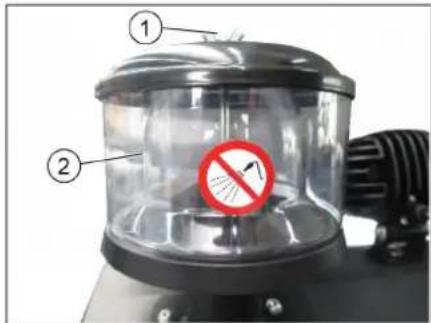
1Баразковаярака
2 LéHTpO6eXhBc cenapatop
OTBnHTntb 6apaUkoByo raKy Ha ueHtpo6exHom cenapatope.
OuHCTnTb ceHTpo6exKbIcenapaTop.
PpOBepntb ypoBeH ndoJIHTb MaIOnDnI rnpaBnuecknx CnCTEm
YBEIDOMJIENHE
Pe3epeyap dna c6opa mycopa He doJxeh 6bimb npunoohm.
OTKpbItbKOxQyX DBnIaTeNa.
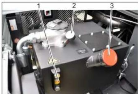
1 Macromephoe cTeKnIO dIg IuapBnIueckoro macna
2 MaHometp
3 KpbIka,OTBepCTne ⅡAJIINBkn MaCna
PpOBepnTy yPOBeHb MacnaB rIpaBnnHeCKO CNCTeME B CMOTPOBM OKHe.
-уpoBeHb Macna DoJIkeH HaxOuTbcra MeKdy OTMeTKamn MIN" n "MAX".
-EcIn ypoBeHb MacnHa HnKe OTMeTKN "MIN",doNTbMacNo.
OTKpyTtB 3anOpHyk KpbIuKy OTBepCTNA Jn3aINBKn MaCna.
OuNCTb 06NaTb 3aJIINBKN.
3aINITb MacNo DnA rnpabnnuecknx CNTeM.
BnD macna: cm. "TexHnueckne daHhble".
3akpyTtB 3anopHyKpbIuKy OTbepCTN DnR 3aJIbKn MaCna.
YBEIDOMJIENHE
Ecnu MaHomemp yka3bIeaem Ha noBbiweHue daBneHua zuopaenueckoO macna, Heo6xodumo o6paumbc8 e cepuechyo cnYk6y Karcher no 60npocy 3aMehbl pfunbmpa dna zuopaenueckoO macna.
PpOBepntb rnpaBnueckyO yCTaHObky
YBELOMNEHNE
Pemohm zuopauneckou ycmahoeku npoeodmb molko cnpueeneh em cepucho cnjkblupmbk Karcher.
3aФнсугTe CTOrHouHbI TOpM03.
3anyctntbDnrtaeJIb.
→ PpOBepnTb repMeTnHocTb Bcex 6e3 NCKJIQUHeHrI rNpaBnueCckNX IJNaHROB n COeINHeHn.
PpOBepKa n o6cnyKuBaHne BODaHoropaHaTopa
Onachocmb
Onachocmb obepubuaHua Kunuee bdo! Damb paduamopy ocmbimb meehue He Mehee 20 Muhym.
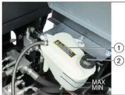
1 KomnHcauHnhb 6aok paHaTopaXIKKOCTHORO OXJaXKeHn
23anopnKa Kpbilka
PPOBepntb ypoBeHb oxnaJdaHOuei BOdbI B KOMNeHcauHOnHOM 6ake (ypoBeHb BOdbI Mekdy OTMeKamM MNH mAKC).
OuNTb nlaCTnHb paHaTopa.
PpOBePnTb repMeTuHOCtB uHaHra paNaTopa n CoeINHeHn.
PpOBepKa nOdMeTaIoue RoBa
3anyTntb DBnraTeB.
→ PtoHnTb do ynpa peepByap dna c6pa mycopa.
BbIKNIOHTbDnIraTeJIb.
3aФнкуTe CTORHouHbI TopMo3.
YcTaHOBnTb PpeOxpaHnTeIbHbIe ⅢTaHn DnA ONOpOXHeHn NOdHrTOr pe3epByapa.
→ YdaNTb C NOdMetaIOUeBO Bana HAMo TaBnecr HeHTb N BepeBKN.
BbHyTb npedoxpaHntbHbIe WtAHn.
3anyctntb DnBraTeIb.
Onycntbpe3epByapnla c6opa MycopaB HauaJIbHoe NOIoxKeHne.
BbIKIOHTb DBnraTeIb.
3aMeHa nOMeTaIooJero BaJa
C onyueHHbIM 6yHKePOM dIa Mycopa.
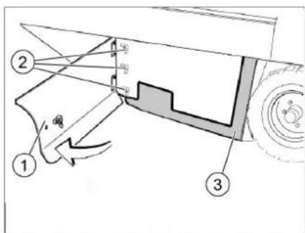
1 BoKoBa nHaHb, npaBa
2BapauKOBa rKa
3 BoKOBoe ynNoTHeHne
OTKpoTe npabyIO 60KOByIO nAHeIb c NOMOJIbIO KIOVA.
OTBnHTb 6apaWkoBbIe raIKn, pacno- NOXKeHHBe Ha NIOCKoI CTOnOPHOI Wai6e,OT 60KOBOr yNtHEnHn CHaTb NIOCKyIO CTOnOPHyIO wai6y.
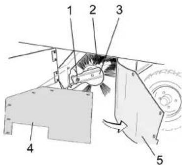
1 Kpenexhbl BnHT depkaTeI naMe-taOueroBaJa
2 MetyuBan
3 DepekateIb noMeTaOuIeRo BaIa
4ПпockасторнаяшайббokoboroynnotheHn
5 BoKOBoe yIIOThHeHne
OTKHyTb HApKy 6okOBoe yIIOThHeHne.
→ BbIBHNTnTB KpENeKHeB BnHT DepKaTe- nIOmTaHOUero Bana N NOBepHyTb HApxyI npEmHOE yCTPOINCTBO.
BbHyTb noDMTeAIOUaI Bn.
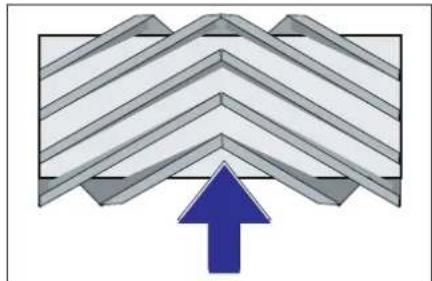
PacnoIoxKeHne noMTeaUoJero Bana npu yctaHOBKe nHaNPaBNeHIO DnXeHn (BND CBepxy)
Yka3aHHe: Pn yCTaHOBKe HOBOr NOIMTeAIOUero Bana CneINb 3a NIOXKeHNEM UeTINbI.
YcTaHOBnTb HOBbI NOmTeaHcNl BAN. Na3bI NOmTeaHcero Bana dOJIK HbI COBNaCTb C BbICTyamn 6aHaCnpa.
Yka3aHHe: Iocne yctaHOBKn HOBOr NOmTaKUcero Bana Heo6xOIMO CHOBa OTpeRyIINPOBaT NIOCKOCTb NOMTeAHH.
PpOBepka N KoppeKTHIpOBKa NIOCKOCTN NOMTeHnI DnI NOMTeAooero BaJa
PpOBepntb DABBHeHne B uHHax.
→ BbIKIOHTb BCacbIBaIOUIN BEHTUNA-TOP
→ NocTABNTb NOMTaIOUyMoAUNHy HaPOBbI rJaDKN NON, NOKpbITbI BUNMmICNOEM bINN INMeJ.
→ C nOMOuBIO pbyHara ynpaBHeHnO nOyCTNTb NOmTaHOUsn BaNk N DaTb emNy npa6oTaTb (ok. 10 c).
→ NpOHTb NpOMTaHouu BaJ.
→ TaTb annapaty 3aHnXoD.
PpoBepntb nIOCKoCTb noDMaTHnA.
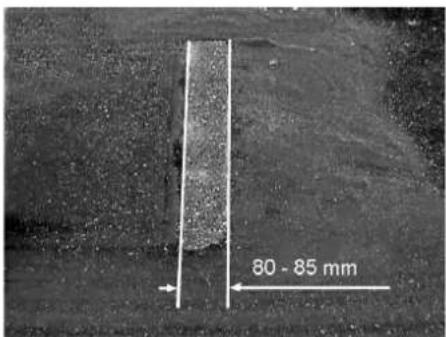
PpOINbIOmMetAHnIOnJxHcNMeTbBVD paBHOMePHOro pRMOyrolhNka WnPNHO 80-85 MM.
Perynpobka npoФиЯ noDmetaHn
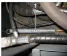
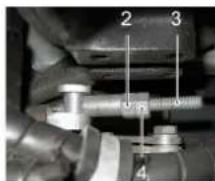
1 p y x n h a
2 Perylnipobouhra raika
3 KɔntpɑnKa
4 Pe3b6oBOI uTOK
→ OtperynnpoBaTb noJoxKeHne npOphnna NOmTaHnIyTeM nepeCTaHOBKn YCTaHOBOHOrO BnHTa.
PpOBePbIPOCKoCTb NOMeTaHnA.
IpoBepka n KoppeKTHnpOBka npoФnna IOdMeTaHnДЯбOKOBbIX ueTOK
PpOBepntb DaBHeHne B uHHax.
→ ΠΟΥΠΜΙΝΕ ΣΟΥΑΜΙ ΣΟΥΑΜΙ ΣΟΥΑΜΙ ΣΟΥΑΜΙ ΣΟΥΑΜΙ ΣΟΥΑΜΙ ΣΟΥΑΜΙ ΣΟΥΑΜΙ ΣΟΥΑΜΙ ΣΟΥΑΜΙ ΣΟΥΑΜΙ ΣΟΥΑΜΙ ΣΟΥΑΜΙ ΣΟΥΑΜΙ ΣΟΥΑΜΙ Ανραβλημ.
→ NocTABNTb NOIMetaUOyMaUNHy HApOBHbI rJaKnI Non, NOKpbITbI BNDMBIM CNOEM nbINnMeJa.
→ Pyhar ynpabHeHn6oKOBbIMn 8eTKa-Mn (3) Bnepei: BoKOBaI 8eTKa onycka-etcra.
→ДаиTe 6OKOBoi ueTke npa6oTaB TeueHne np6JI.10 ckyHd.
→PnnoHrB6okOBbIe 1eTkn.
→ TaTb annapaty 3aHnXoA.
PPOBepntb nIOCKOCTb NOIMTaHnA.
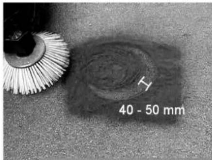
HnHa npoФnI npOMeTAHnI DOnKHa COCTaBnTb OT 40 Do 50 MM.
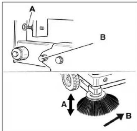
→ OtperynipoBaTb nIOJoxHeHne nIOCKoCTN NOIMTeHaHc NOMOUsIbO DByX yCTaHOBOUHbIX BHTOB.
PPOBepNTb NIOCKOCTb NOmTaHnA.
yctahOBt60KObBle yNIOTHEHn
PioBepntb DaBneHne B uHaX.
→Понгь Вьерх pe3epByap Дясбopa Mycopaи 3аФИКСИРОВытс NOMOUIbI npdeoxpaHHTeBHOJ uTaHn.
ONACHOCTb
Onachocmb nonyeHnmpaB! Bce2da npu noohmom pe3epeyape dna c6opa Mycopa ycmaHaenueamb npedoxpahumenb Hbie omaneu.
OTKINHTb HabePx npdeoxpAHNTeHHyIO WtAHry IaI ONOPOXHEHnI NOHrTOro pe3epByapa N BCTaBnTbe B depXaTeNb (npdeoxpAHNTeHbH)
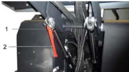
1 DepeKateJI npedeoxpaHHTeJIbHOI 7TaHn
2 PpeoXpaHnteBnaa TaHa
OTKpbItb 60KOByHnaneHb, KaK OINcaHO Brrabe ,3aMeHa NODMaTOUeroBana" Bblwe.
Ocna6b6apawkoBbIXraekHa60-KOBoI pnocko CTOnOpHoi waiBe.
OcnaBntb 3 raKn (SW 13) Ha nepeDHei nnocko CTOnOpHO WaiBe.
Hakimatb60koBoe yNIOHTHeHne BHN3 (npoOnbHOE OTBepCTne) Do tex nop, NOKa eRcKpaH He OKaKeTcHa paCTo- RHN1-3MMOTnOJa.
→PnBnHTnTb nIOCKyIO CTONOPHyO wai-6y.
→ NOBTOPNBIOCEIOBATENBHOCTbIpyoCtPOHOYyCTPOHCTBA.
HeicnpaBbIe npedoxpaHHTeIN 3ameHNTb.
Yka3aHne: NcOnb3ObaT TOJIbKO npedoxpaHHTEN COnHaKOBbIM 3HaueHnEM.
3aayBneHne o COOTBeTCTBn EU
HactoM Mbl 3aBnem, yTo HxkeyKa-3aHHb Pn6bp NO CBOe KOHcENuN KOHCTpyKUn, a TAKKe B OcyueCTBHeHOM N DOnyUeHHOM HAMN K PPOdaXe NCIOJIHeHN OTBeaet COOTBeTCTBYUUM OCHOBHbIM Tpe6ObaHnM IO 630NaChOCTN IN 3DopOBbIO cornaCHO DupeKTHBaM EU. PnBHeCENN N3MeHEN, He CoTlacOBaHHbIX C HAMN, DaHHOe 3aBHeHne TepaET CBOK CNJy.
PpOdyKT PpOMeTaHua MaunHa C MECTOM DnB ODoNTeN
Tun: 1.186-145.0
OCHOBHbIe dIpeKTHBbI EU
2006/42/EC (+2009/127/EC)
2014/30/EC
2000/14/EC
PpIMMeHHbIe rapMOHn3npoBaHHbIe HopMbI
EN 60335-1
EN 60335-2-72
EN 55012: 2007 + A1: 2009
EN 61000-6-2: 2005
EN 62233: 2008
IpIMHeHHbIe BHyTpnurocydapCTBeH HbIe HopMbI
PpmeHHbI NopdOK OeHKn COOTBETCTB
Chairman of the Board of Management

S. Reiser
Director Regulatory Affairs & Certification
YIOJHOMOueHHbI COtpyDnIK NO BeDeEHIO DOKymeHToo6oPota:
S. Reiser
Alfred Kärcher SE & Co. KG
71364 Winnenden (Germany)
Tel.: +49 7195 14-0
Fax: +49 7195 14-2212
Winnenden, 2022/02/01
Pomoub B cnyae HenoJaok
www.kaercher.com/REACH
Garancia
71364 Winnenden (Germany)
Tel.: +49 7195 14-0
Fax: +49 7195 14-2212
Winnenden, 2022/02/01
www.kaercher.com/REACH
Záruka
2006/42/ES (+2009/127/ES)
2014/30/EU
2000/14/ES
2000/14/ES: Přloha V
71364 Winnenden (Germany)
Tel.: +49 7195 14-0
Fax: +49 7195 14-2212
Winnenden, 2022/02/01
Pomoc pri poruchach
www.kaercher.com/REACH
Garancija
Zadevne directive EU:
2006/42/ES (+2009/127/ES)
2014/30/EU
2000/14/ES

Chairman of the Board of Management
Director Regulatory Affairs & Certification
71364 Winnenden (Germany)
Tel.: +49 7195 14-0
Fax: +49 7195 14-2212
Winnenden, 2022/02/01
www.kaercher.com/REACH
Gwarancja
2006/42/WE (+2009/127/WE)
2014/30/UE
2000/14/WE
H. Jenner Chairman of the Board of Management
S. Reiser
Director Regulatory Affairs & Certification
Administrator dokumentaci:
S. Reiser
Alfred Karcher SE & Co. KG
71364 Winnenden (Germany)
Tel.: +49 7195 14-0
Fax: +49 7195 14-2212
Winnenden, 2022/02/01
Usuwanie usterek
www.kaercher.com/REACH
Garantie
Verificarea presiunii in envelope
Directive UE respectate:
2006/42/CE (+2009/127/CE)
2014/30/UE
2000/14/CE
Norme armonizate utilizezate:
EN 60335-1
EN 60335-2-72
EN 55012: 2007 + A1: 2009
EN 61000-6-2: 2005
EN 62233: 2008
Norme de aplicare nationale:
71364 Winnenden (Germany)
Tel.: +49 7195 14-0
Fax: +49 7195 14-2212
Winnenden, 2022/02/01
www.kaercher.com/REACH
Záruka
Udrzbapop50prevdzkovychodinach:
2006/42/ES (+2009/127/ES)
2014/30/EU
2000/14/ES
2000/14/ES: Priloha V
71364 Winnenden (Germany)
Tel.: +49 7195 14-0
Fax: +49 7195 14-2212
Winnenden, 2022/02/01
www.kaercher.com/REACH
Jamstvo
U svakoj zemplji vaze jamstveni uvjeti koje je izdala naša nadlezna organizacija za distribuciju. Eventualne smetnje na stroju za vrijeme trajanja jamstva uklanjamo besplatno ukoliko je uzrok greška u materijalu ili proizvodnji. U slučaju koji podliježe garanciji obratite se, uz prilaganje potvrde o kupnjni, Vašem prodavacu ili njblžoj ovlastenoj servisnoj službi.
Funkija
Stroj za metenje radi na principu lopatica za skupljanje prljavstine.
- Rotirajuči valjak za metenje prenosi priljavžtinu izravno u za to predvideni spremnik.
- Bočna metla skuplja prljavstinu iz kutova i s rubova povrsine koja se cisti i prošljeduje je u stazu kojom se kreće valjak za metenje.
- Usisni ventilator usisava finu prasinu kroz odgovarajuci filtrar.
2006/42/EZ (+2009/127/EZ)
2014/30/EU
2000/14/EZ
Primijenjene uskladene norme:
EN 60335-1
EN 60335-2-72
EN 55012: 2007 + A1: 2009
EN 61000-6-2: 2005
EN 62233: 2008
Primijenjeni nacionalni standardi:
Chairman of the Board of Management
S. Reiser
Director Regulatory Affairs & Certification
Opunomoćeni za izradu dokumentacije: S. Reiser
Alfred Kärcher SE & Co. KG
71364 Winnenden (Germany)
Tel.: +49 7195 14-0
Fax: +49 7195 14-2212
Winnenden, 2022/02/01
www.kaercher.com/REACH
Garancija
2006/42/EZ (+2009/127/EZ)
2014/30/EU
2000/14/EZ
Primenjene uskladene norme:
EN 60335-1
EN 60335-2-72
EN 55012: 2007 + A1: 2009
EN 61000-6-2: 2005
EN 62233: 2008
71364 Winnenden (Germany)
Tel.: +49 7195 14-0
Fax: +49 7195 14-2212
Winnenden, 2022/02/01
| Otklanjanje smetnji | |
| Smetnja Otklanjanje | |
| Urežaj se ne mozePokrenuti | Sedite na sedište vozača, kontaktni prekidača sedišta vozača se aktivira. |
| Punjenje ili zamena akumuladora | |
| Ulije gorivo, ispustite vazduh izsystema goriva | |
| Zamena filtera za gorivo | |
| Zamena predfiltera za gorivo | |
| Proverite i po potrebi popravite system vodova za gorivo, priključke i spojeve. | |
| Obavestite Kärcher servisnu službu. | |
| Motor radi neravnomero | Očistite filter za vazduh ili zamenite filterski uložak. |
| Proverite i po potrebi popravite system vodova za gorivo, priključke i spojeve. | |
| Obavestite Kärcher servisnu službu. | |
| Pregrejan motor Dopunite rashladn | sredstvo |
| Isperite hladnjak | |
| Zategnite klinasto remenje | |
| Obavestite Kärcher servisnu službu. | |
| Motor radi, ali se urežaj kreće sporo ili nikako | Otokočite pozicionu kočnicu |
| Proverite da nema upleteni traka ili petlji. | |
| Obavestite Kärcher servisnu službu. | |
| Pišteci zvuk u hidraulici Sipajte hidral | aulicku tečnost |
| Obavestite Kärcher servisnu službu. | |
| Četke se vrte polako ili se uopšte ne vrte | Papučicu za gas postavite sasvim prema napred (visok broj obrtaja). |
| Proverite da nema upleteni traka ili petlji. | |
| Obavestite Kärcher servisnu službu. | |
| U prostoru Četki je usisna snaga mala ili je uopšte nema | Čišćenje filtera |
| Obavestite Kärcher servisnu službu. | |
| Urežaj diže prašinu Podešavanje b | pčihn zaptivki |
| Ukliguje ventilator. | |
| Očistite filter za prašinu | |
| Zamenite filterske zaptivke | |
| Obavestite Kärcher servisnu službu. | |
| Jedinica za Čišćenje ostavlja priljavžtinu da leži | Ispraznite posudu za nakupljenu priljavžtinu |
| Sasvim zatvorite posudu za priljavžtinu. | |
| Očistite filter za prašinu | |
| Zamenite valjak za metenje. | |
| Naknadno podesite profil metenja | |
| Zamenite zaptivne trake na posudu za priljavžtinu | |
| Uklonite strana tela koja blokiraju valjak za metenje | |
| Obavestite Kärcher servisnu službu. | |
| Posuda za priljavžtinu ne moze da se podigne ili spusti | Ukloniti saigurnosni podupirac sa posude za nakupljenu priljavžtinu |
| Obavestite Kärcher servisnu službu. | |
| Posuda za priljavžtinu se vrti presporo ili se uopšte ne vrti | Obavestite Kärcher servisnu službu. |
| Smetnje u radu s hidraulickimPokretnim delovima | Obavestite Kärcher servisnu službu. |
| Teknički podaci | ||
| KM 170/600 R D Classic | ||
| Podaci urežaja | ||
| Brzina vožnje prema napred km/h 14 | ||
| Brzina vožnje unazad km/h 14 | ||
| Savladavanje uspona (maks.) -- 18% | ||
| Površinski učinak bez bočnih metli m | 2/h 18800 | |
| Površinski učinak sa 1 bočnom metlom m | 2/h 23800 | |
| Površinski učinak sa 2 bočne metle m | 2/h 28000 | |
| Radna širina bez bočne metle mm 1344 | ||
| Radna širina sa 1 bočnom metlom mm 1700 | ||
| Radna širina sa 2 bočne metle mm 2000 | ||
| Stepen zašite, zašićeno od kapajuće vode -- IPX 3 | ||
| Trajanje primene sa punim rezervaorom h 4,5 | ||
| Motor | ||
| Tip | -- Kubota | V1505 (E4B) |
| Tip | -- 4-cilindrični | četvorotaktni dizel motor |
| CO-Emisija u skladu sa postupkom merenja EU odredbe 2016/1628 (stepen V) | g/kWh | 1018,0 |
| Način hlăjenja | -- Hlaadenje vodom | |
| Smer obrtanja | -- Suprotno smeru kazaljke sata | |
| Radna zapremina | cm³ | 1498 |
| Maks. snaga | kW/PS | 18,5/24,8 2300 1/min |
| Akumulator | V, Ah | 12, 72 |
| Radni mediji | ||
| Količina motornog ulja | I | 6 |
| Tip motornog ulja | >25 °C | SAE30, SAE10W-30, SAE15W-40 |
| 0 - 25 °C | SAE20, SAE10W-30 | |
| < 0 °C | SAE10, SAE10W-30 | |
| Hidrauličko ulje | -- Renol HV 46 | |
| Količina hidrauličkog ulja | I | 37 |
| Rashladno sredstvo (SAE J814C) | -- Stilmoil Antifrost | |
| Za mesta podmazivanja koja treba ručno podmazati | Višanamensko mazivo | |
| Posuda za nakupljenu prljavštinu | ||
| Maksimalna visina pražnjenja | mm 1540 | |
| Zapremina posude za prljavštinu | I | 600 |
| Valjak za metenje | ||
| Prečnik valjka za metenje | mm 400 | |
| Širina valjka za metenje | mm 1344 | |
| Broj obrtaja | 1/min | 340 |
| Profil metenja | mm 80 | |
| Bočna metla | ||
| Prečnik bočnih metli | mm 650 | |
| Broj obrtaja (kontinualno) | 1/min | 0 - 63 |
| Gume | ||
| Veličina napred | -- 6.00-8 | |
| Pritisak vizduha napred | bar | 8 |
| Veličina pozadi | -- 5.00-8 | |
| Pritisak vizduha pozadi | bar | 8 |
| Kočnica | ||
| Prednji točkovi | -- mehanička | |
| Zadnji točak | -- hidrostaticka | |
| Filterski i usisni sistem | ||
| Tip - Pljosnati naborani filter | KM 170/600 R D Classic | |
| Broj obrtaja 1/min 2900 | ||
| Površina filtera za finu prašinu m | 2 | 9,1 |
| Nominalni podpritsisak usisnog systemd mbar 18,5 | ||
| Nominalni zapreminski protok usisnog systemd m | 3/h 1650 | |
| Vibracioni system -- Elektromotor | ||
| Okolni uslovi | ||
| Temperatura °C -5 do +40 | ||
| Vlažnost vazduha, bez stvaranja kondenzata % 0 - 90 | ||
| Izračunate vrednosti prema EN 60335-2-72 | ||
| Emisija buke | ||
| Nivo zvučnog pritiska LpA | dB(A) | 82 |
| Nepouzdanost KpA | dB(A) | 3 |
| Nivo zvučne snage LWA + nepouzdanost KWA | dB(A) | 103 |
| Vibracije urežaja | ||
| Vrednost vibracije na ruci | m/s2 | 0,7 |
| Nepouzdanost K | m/s2 | 0,2 |
| Sedište | m/s2 | 0,5 |
| Nepouzdanost K | m/s2 | 0,1 |
| Dimenzije i težine | ||
| Dužina x širina x visina | mm | 2742 x 1904 x 2213 |
| Poluprečnik okretanja udesno | mm | 2525 |
| Poluprečnik okretanja ulevo | mm | 2490 |
| Prazna težina (bez dodatnih sklopova) kg 1695 | ||
| Dozvoljena ukupna težina | kg | 2701 |
| Dozvoljeno opterećenje prednje osovine | kg | 1703 |
| Dozvoljeno opterećenje zadnje osovine | kg | 998 |
| Zapremina rezervaora za gorivo, dizel | l | 26 |
| Zadržavamo pravo na tehnicke promene! | ||

IpeNn PbBTO N3N013BaHe Ha Baunya ypei npoTeTe TOBA
opnHnHaHNO nHCTpyKcyy 3a pa6oTa,
IeNCTBaIte CnpoeI Hero I ro 3ana3eTe 3a
IO-KbCHO n3noJ3BaHe nJIn 3a CneDbaun
npTeKaTeI.
CbDpbXaHne
Yka3aHna 3a 6e3oNaChocT...BG1
CmboJn Ha YnbTbaHeto 3a
ynoTpe6a .BG1
CnmboHnHa ypea...BG1
067uka3aHnB .BG1
Ona3BaHe Ha OKoJHaTa CpeDa BG 2
TapaHua. BG 2
Функць BG2
YnoTepe6a no npedHa3NaueHne BG 2
PoiXoJraHnHaCTnIKN..BG2
ObnykBaunn yHKUHOHaHn
eJIeMeHTn BG 3
1306paXeHHe Ha MaunHaTa
3a MeTeHe BG 3
06cnyxbaaenueMeHTN BG3
PpeDn nyckaHe B eKcnIIOaTa-
L. BG 4
Блokиран/ocвбождава-
He Ha 3actonopraaata
CnnpaKa .BG4
3aDnBxKBaHe Ha MeTaHaTa
MaunHa 6e3 CO6CTBeHo
3aDnKBaHe. BG4
3aDnBxKBaHe Ha MeTaHaHaTa
MaunHa Cbc Co6CTBEN XoB BG4
Iyckahe B eKcnnoatauia .BG4
06u yka3aHnB .BG4
KoHTpOJIHHIIOIDbPjKaaui
DeHocTn BG 4
Eknoataa BG 4
Ia ce HacTpon cedankata
HaBoaa..BG 4
CTapTnpaHe Ha ypea..BG4
TbTuBaHeHa ypea. . . BG 5
PexMM MeTeHe. BG 5
Da ce n3npa3Hn pe3epBoapa
3a 13MeTeHOTo. .BG 5
I3knHouTe ypeHa... BG 6
TpaHcnpT. BG 6
CbxaheHne/CnnpaHe .BG 6
IpnKn n npDpBxKa .BG 6
06u yka3aHnB .BG 6
Почистван. BG 6
INTepBaHnHaNoDpBjKbBG 6
IeHocn no noDpBkKaTbG 7
ECДeKnapaua 3a cBoTBeT-
CTBNE. BG 11
IOMOu npn HEn3npaBHOCTN..BG 12
Texnueckn daHHN BG 13
Ykaahna 3a6e3onachocT

Onachocm om yxpexdahe Ha cnlyxa. Tpbea da ce hocu 3auuma 3a cnlyxa.
CnmboHnHa YnbTbaHeTo 3a ynotpe6a
ONACHOCT
3a HenocpeodcmeeHO 2pO3uO anacHocm, KOmo bdu do meKu meLecHu nopeDu Unu do cMbpm.
△PENEYNPEXKDEHNE
3a 3MOxHa onachacumyaucu, KOmo 6u moana da doeede do mexku menechu noepedu uU cmbpm.
PPEIIA3NIOBOCT
3a 6b3MOxHa onacha cumyaun, Koymo 6u moJana da doBeDe do neku meJeCHu noepeDu unu MamepuanHu uemu.
CnmboHa ypea
Onachocm om u3eapnHe npadu zoepu noBpHnocmu!PpeDu paBoma no ypeDa, ype6bama Ha aycnyxa da ce ocmaeu da ce oxlaDu docmambHo.

U38bpuwaume paobomama no ypeda c noxdoxoou pkaeuu.
Onachocm om npuunbea He nopadu zakleuebahe Mexdy nodBxku h yacmu Ha npeo3Hmo cpe-cmeo.

Onachocm om HapaHreaHe npadu noduXku yacMu. He 6bpkaume bvmpe.
Onachocm om noxap. He 3acmykaume aopu unu mneeu npedmemu.
3aKpenBaHe Ha eepuzama /moKa 3a OkauBaHe Ha KpaH uKupaHa moKa 3a 3aKpeneaHe
HaIyahe Ha zymume (MaKc)
Tooku 3a 3ax6aune Ha aemomobunnua KpuK
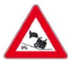
MaKcUmaJIeH NaIIOH Ha OChObAma npu npuDuxKeaHe c noBdu2Ham pe3ep-oeap 3a u3MeMeHomo.
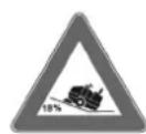
No nocoka Ha deuxkehuemo npemuhaaume camo no hakoHou do 18%
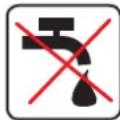
Onachocm om noepeda! He muimte fummbpa 3a fun npax.
06uynka3aHn
Ako npi pa30nakOBAhe yCTaHOBtE TpaHCnopTHa NOBpeHa, yBeDomete MaRa3HHa, OTO CTe 3aKynnnypeHa.
-Пудунпсдгннчу yka3aTeHnHTe Ta6eJHKHa ypeJa DaBaT BaxHn HaNbTCTBn 3a 6e3oNa cHa pa6To.
OcBeH yKa3aH 3aeknloataun Tpr6Ba Da ce cna3- BAt N O6uNTe HOpMaTHBn INpeDnncA Hn 3a 6e3oNaCHOCT IN ppeDn3BaHe OT 3IOnOJyKn.
Yka3aHn3a pa3TOBaPaBaHe
Onachocm
Onachocm om HapaHraVeHe, onachocm om yepexkahe!
Ppu pa3moBaepahe umaume nped bud meJnomo ha ypeda!
www.kaercher.com/REACH
Fapancy
Bb BcKa cTpaHa BaKaT rapaHcIOHNHTe YcIOBn, Np6IkyBaHn OT OTOPI3npaHata OT Hac DNCTPb6yTopcKaΦnpMa. EBeHTy- aHn NOpeu Ha Baun ypei ue OTcpanHM B pAMKNTe Ha rapaHcIOHnC pOK 6e3PiAtHO, Ako CE Kacae 3a DeΦeKT B MaTePNaNTE nn npn npOn3BOvctBO. B rpaHcIOHEn CnyaH CE ObpHeTe KbM DCtPb6yTopa NN Na-6JI3KNr OTOpN3npaH cepBn3, KaTo npeDcTaBnTe kacOBaTa 6eJexkka.
Функця
MaunHata 3a MeTeHe pa6OTn IIO npHnCuHa Ha JONaTATA 3a MeTeHe.
-BbptraunrCTceMeTnBaalkN3npaMa MPbcOTnTa DnpeKTHo B pe3epBoapa 3a N3METEHOTO.
-CTpaHnHnata Metna NOUHCTBa BrInTe N KaHTOBETe Ha NOBbPxHOCTTa 3a MeTeHE HnIaPaaMpbCOTnTbByNeHa METAUNBAJAK.
-ФИнгЯТ npax ce 3acmykBa npe3 ФинТьра 3a npax C NOMOHTa Ha CMykaTeJHnY yNoBNTeJ.
Ynotpe6a no
PpeDHa3HaueHHe
N3IOI3BaIte Ta3n MetaHa MaUNHa CAMOB CbOTBETCTBNE CbC 3aDaHTe B HACTOyTbTBAHe 3a EKcNIOaTAuJ.
YpeBt C npncnoc6neHnraTa 3a pa6o Ta npeN u3NONBaHe Da ce npOBepu 3a 6e3ynpueHo cBCTOHRHe u EKcNIO-ataaONHa cnrypHOct. Ako ypeBt He e B OTJNUHc bCToHne, u3NONBaHeto My e 3a6paHeHO.
-Ta3n MeTaUHa MaSiHa e npEiHa3Ha-yeHa 3a MeTeHe Ha 3aMbpcHn NO-BbpxHOCTN HABhN.
-He ce no3B0nlaBa n3noJ3BaHeto Haypea B 3aTBOpEn NOMOSeHHN.
- Ypeinte, Bbpxy KOnTo ce cedn, 6e3 PNOxOJaIIO OobpyDbaHe (pa6pnuHa ONiHa) He ce donyckat B objcctBeha-Ta PbTHa Mpeka.
-YpeMaMOKeJaCeN3NON3BaJaDINBIXeHHeIOObIeCTBeHN TpaHCnOpTHINbTNIUcCaMoCJIeIHINDbNIDyAJIHOPiMeMaHEOT CNYKeBEN KOHTpONeH OprAH.
-BCnKn KanaHn Ha ypeHa Tpr6Ba Da ce OTBaprT cAmO B 3aunTeH N OT B0Da 3OH.
- YpeBbT He e IIOxOJaI 3a I3cMcyKbaHe Ha 3actpaawabaun 3npabeto npaxOBe.
-No ypeHa He Tp86Ba Da ce npednpne-MaT npomeHn.
- HnKora He n3mTaTHe/3acMykBaHTe EKCnIO3NBHN TeuHOCTN, Bb3PiJaMeHa-Emr Ra3OBe, KaTO H He pa3peDeH NKeCenHn Pa3TBOpHTeH! KbM Tx npHaJnEkaT 6eH3Hn, pa3peNTeH 3a 60 Hnn Ma3yT, KOTo np3 aBnXpHRe C Bb3Dyxa 3a BCMyKBAHe Moar Da O6pa3yBaT EKCnIO3NBn Napu Nn CMecn, OCBeH TOBa aUeToH, He pa3peDEH KcEINHn N pa3TBOpHTeN, Tb KATO Te aTakyBat N3NoN3BaHnTe 3a ypeDa MaTePnAIn.
-He n3mntaIte/3acmykBaIte ropaun nn Tneeus npedmetn.
- YpeBt e noxOraIc amo 3a onncAHTe B YntbTaHeto 3a ekcnnoatauia no-KpTna.
-Morat da ce MInaba cAmo no nobpx-HOCTn, N03BOJEnH OT npednpemau HINHEROBITE yNbHOMOueHN JIua 3a H3NOJ3BaHe Ha MaunHNTe.
-3a6paHbBa ce npceToB bOnachn Obnactn. 3a6paHeHa e pa6oTaTa BbB B3pNBOONACH NOMeUeHn.
- P O n p H u n B TepnnaIa ce Ibprkat daneye ot ypeia (OnachocT OT EKcnnO3n/ noxap).
IopxoadyHnactnkn
ONACHOCT
Onachocm om hapaHaahe! Ppoeepem mobapohocumocmmha ochoema, npedu da npemuHeme no He.
-Acpaant
- INHducptpnaJIHnI IOdoBe
-UMMeHTOBINIOBOBE
- B e T o H
- Па вета
IPEDA3NBOCT
Onachocm om yepexdahe! He uzmumaume lehmu, uhyoee unu men, 3aouomeme Mozam da ce 3aeum okono Memuaea bajk.
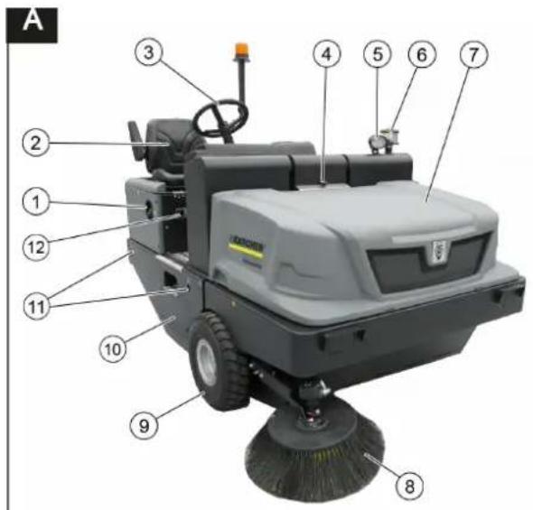
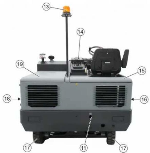
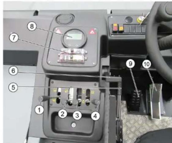
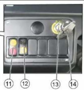
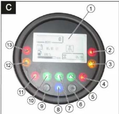
H3o6paXeHne Ha MaunHaTa 3a MeTeHe
Phiaypa A
1 Kanak Ha pe3epBoapa
2 CeDAnKa (c KOHTaKTeH npeKbcBaHu Ha ceDAnKaTAt)
3BoJahN
4БлokировkaHaKanakaHa ypeda
5 Blue Spot (onuohanho)
6 Lehtpo6exeH OTdienTeI
7 Kanak Ha ypeda
8 CtrpaHnHa MeTla,OTdACHO
9 PpeDNo kOJIeNo
10DocTbI Do MeTaunBaanK
11ФИКСИРанTOUka3a3akpeNBaHe
12 Tynoba Tabenka
13 AbaruHa JAmna 3a CBTeHe HaOKO
14 06cnykBaun eJemeHTN
15 Kanak Ha ypea OTrACHO
16 Nokpntne,OTdRcHO
17 3aDbVbKBaUo KoIeNo
18 Nokpntne,OTJRABO
19 Kanak otTnBaBO (kanak Ha DnBraTeTn)
06cnykBaun eJeMeHTN
Quaypa
1Ioc3a ynpabHeHHe Ha MetraUBAJRAK BKIOUBAHe/H3KIOUBAHe
2Ioc3a06cnykBaHe Pe3epBoap 3a n3Me-TeHOTOBdHaHe/CtYCKAHe
3Ioc3aO6cnykBaHe CtpaHnHa MeTna BmraHe/CnyckaHe
4Ioc3aO6cnyBaHeKanKaHape3epBo-apa om8apnHe/3am8apnHe
5 3actonopraa cnpaKa
6БpoaHаObOpOTteHaMOtopa Joc3ra3Ta
7IpeDn3nteH
8KoHTpOJIHnIaMnIuMcIIeN
9 C n np a q e H ne d
10 PdJIaI 3a DnIXeHne HnpeI /Ha3aI
11 PpeKbCBAu BeHTnlaTOp nNouchTaBaHe HaΦnTTbaPa
POnOxHne B CpeaTa: NouchTaBaHe HaΦnTTpaN BeHTnlaTOp n3Kn
POnOxHne HAnpeD: BeHTnlaTOp BKn.
POnOxHne Ha3aD: NouchTaBaHe HaΦnTTpa BkI.
12ПпeксвачknakcoH
13 3anaIHTepen KIOU
IonoXeHne O: N3KnIOuBaHe Ha DBIrataTeN
IonoXeHne 1: 3anaIbaHe BKn
IonoXeHne 2: CtapTupaHe Ha DBIrataTeN
14 KIIOU 3a DoCTbN Do MeTReuTe BaJIaUN
KohtpOJIHn IaMnn N DInCnIeN
Quaypa
1 Poka3aHne Ha dinCnIe
O6opOTn Ha DnBraTeJIa
POncTbAHe Ha FmITbpa AkTNBHO
KanaHTet Ha akymyIaTopa
BpOry Ha pa60THnte YacOBe
Poka3aHne Ha pe3epBoapa
2 CnHaHa NaMaHa 3a TempepaTpaTa Ha oxnaJaTa Boda
3 KOnTpOHa IaMaI NapeBapuTeJIHO Ha-ropeuaBaHe
4KoHTpOHaJaMnKaNakHape3epBo-apa 3aOTnAdbuN 3aTBOpEn
5 CnHaHa JAmHa KanKa Ha pe3epBoapa 3a OTnAbuOnTOBpeH
6 He3aET
KoHTponHa JAmna Ha MmraHrTe He3aET
8 Hd n Ka u C 9 He3aET
10 KoHTpoJIHa JIaMna Pa6oTHO OCBeTJeHHe He3aET
11 KoHTponHa JAMnHa aKymyIaTopa
12 CnHaJIHa JAmMa pe3epBa Ha roPnBoto
13 CnHaJIHa NaMna 3a HaJIraHrTo Ha MaCNoTO
Ipei nyskahe B ekcnnoataun
Блokиран/ocBбобдаВаHeHa 3actonopBaцаТспрачka
Yka3aHn 3a 6e3oNaCHOCT aKymyIaTopi
Ppi pa6oTa c akymyIaTOPnTe henpeMeHHO Cna3BaIe CJIeHNITe PpeDyIpEiTENH Yka3AHN:
| i | Спазаиме указаньама на akymулиора, в льмени- mo за улomреба у в Incмту- цума за ekсплоамацу на празовоземо среемо! |
| Hoceme зашиima за очime! | |
| Дръжme Deцама Нассану om киселени u om akymули- mорu! | |
| Опасносм om ekсплоизу! | |
| Збравявам се оьн, ускру, omkrрumsa севлени u пух- né! | |
| Опасносм om разяжданe! | |
| Пърета пооч! | |
| Указамени заменека! | |
| Изхьрлени! | |
| Pb | Акумулиама за не се xьр- 个项目 в костама за бokлун! |
△Onachocm
Onachocm om ekcnno3u! Bbpxy akymy-namopa, m.e. bbyx kpaHume noHocu u cebp3aHemo ha KneMkume da He ce nocmaabm unHcmpymenu unn noo6hu.
Onachocm
Onachocm om HapaHaehe! Hukoza He dokoceaume paHume c onofo. Cnepaoba ma no akymamopume eunau noucmbaume pbueme cu.
ONACHOCT
Onachocm om nojap u ekcnnoia!
- 3a6paHaeam ce nyueHe u omKpm ozbH.
Iomeuhenura,8Koumo ce 3apek-dam akymnamopu,mpr6ea da ce npo-empraam do6pe,mbukamo npu 3apekdahe ce o6pa3yeam bucokoekcno3u6hu 2a306e.
Onachocm
Onachocm om pa3jdahe!
-
Ppcku om kucenhu e oumme unu no koxama da ce u3nnaekam pecn. u3Mu- am c yucma eoda.
-
Cnod moea He3a6a6Ho da ce nombpcu nekap.
- 3ambpceHomo obneKno da ce u3nepe c e0da.
NoctabeTe akymyNatopa n ro noDBpbkete
NocabeTe akymyNaTopa B Hocaya 3a akymyNaTopa.
→ Da ce 3aBnT 3dpaBO DbpxKaHTe Ha nOda Ha akymyNaTopa.
→ Μοῦςθητα Μεμα (υρβεν Μακεπ) Ας Μοῦςθρχε ἀνηλικόσουν Μοῦς (+).
Da c e NODBpKe NOHcHaTa KHeMa Ha MNHycoBnA NOIoc (-).
Yka3aHne: NIOIOCTe Ha akyMylatopa n NOIIOBOITE KNeMn Da ce npOBeprT 3a DOCTaTBuHa 3aUHTa CbC CMA3Ka 3aUHTa Ha NIOHCN.
Ia ce npoBepn n da ce Kopurupa HNBOTO Ha TeuHocTtHa akymyntopa.
PNEI3NBOCT
Ppu HanbIHeN C KucenHa Akymyamop peoHo npoeepaume Hueomo Ha meuHocmma.
-KnceJIInHaTa Ha n3zINo HAnbJIHeN aKymyNaTOp npn 20°C nMa cneuФnHoTerJIo ot 1,28 Kr/π.
-KnceHnHaTa Ha qactuHNo 3apeDen AkyMyNaTOp NMa CneUPhiNHO TerNo MekDy 1,00 n 1,28 Kr/π.
-BBBCNUKKNETKNCNEUΦNHOTo TEIHOHa KINCEJIINHATA TpRA6Ba Da 6bde eHNaKBO.
Pa3BbBaIe BCnKn KaNaYeTa Ha KNeT-KIte.
→OTBCsKaKneTkaDaceB3eMe npo6a c KOHTpOJIbOp Ha KInCeIINH.
PpO6aTa OT KInCeJIINHaTa OTHOB Da ce BbpHe BCbUaTa KJETKa.
→ПиТБьрднИСКО HINBO HA TeCHOCTTAДONbJIHHeTe KJIeTKIte C DECTUNIPAHBOda Do MapKIpOBkata.
3apeTe akyMynaTopa.
3aBnTe kanaeTaHa KneTKnte.
3apeede akymynaTopa
Onachocm
Onachocm om hapaHaehe! Da ce cna3- eam pa3npopebume 3a 6e3onachocm npu bopaeene c akymyamopu. Da ce cna3ea YnmbaHemo 3a ynompeba Ha npou38o-dumena Ha 3apdHomo ycmpoucmeo.
Onachocm
Akymnyamopa da ce 3apedu c noxdyaio 3apdo ycmpoucmeo.
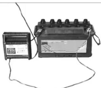
Pa3BnBaIe BCnKn KanaHcTa Ha KNETKeT.
KabenonoxkTeHnnonocHa3apJHOTOyCTPOINCTBOdaCECBpKeCn3BODaHaNIOXkTeHNnNONOCHaakymyIaTopa.
KaBEn OtpuataTeH noHoc Ha 3apnHOTO yCTPOINCTBO Da CE CbPKe C N3BODa Ha OTPuataTeHNHa NOHc Ha aKymyNaTopa.
→ Da ce noctabn Mpejoknbu ukeep n da ce BkHouN 3apdHOTO yCTpOHTBO.
→ AkymyIaTopa Da ce 3apeNi C Bb3MOK-HO Hn-MaBk 3apJeH TOK.
Yka3aHHe:KoratoakymnatoptbCe 3ape- n,3apAnHOTo yCTpOInCTBO Da ce OTKauN npBPOOT MPexkata,a CneT TOBa OAtakymy- naTopo.
DemoHTaK Ha akymyNaTOP
OTkaueTe noJIIOCHaTa KneMa OT MHy-COBnI NOHc(-).
OTkaHETe NIOHOCHATA KINEMAOT NIOHOBNA NOIIOC (+)
Ocbo6oTeHocaHTeHaIOnaHaakymyntopa.
→ CbaIeTaeakymyIaTopo aT Hocay3a akymyIaTopa.
OTcTpaHETe n3paXoDHeNnAkyMyna-Top KaTO OTnAbk CbIaCHO BaINHnTe pa3npoe6n.
Ja ce npOBepn HNBOTHa MOTOPHOTOMACNO n da Ce dOJeMacNo
Onachocm
Onachocm om u3aaphe!
→ MoTopa da ce octaBn da ce oxlaan.
→ PpOBepKa Ha HnBOTO Ha MOTOPHO MacNo Da Ce N3BbPnHnHa-paHO 5 MHyTN CneNnKNIIOHbAHe Ha MOTopa.

1 3aTbapu Kaak, OTBOP 3a nbHe He Ha MacNo
2 Macnon3mepntenHa npbUka
Da ce n3BaI MaCIOI3MePITeJIHaTa npbUka.
Da ce n3tpne Macnon3mepntenHaTa npbka N da ce nbxHe.
Da ce n3BaHn MacNoHmepuTeJIHaTa npbUka.
OTyHTaHe Ha HnBOTO Ha MacIIOTo.
ΠbXHETe OTHOBo MaCJIOU3MepuTeJIHa-Ta npbKa.
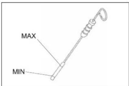
-HNBOTOHaMaCIOTo Tp6BaJa6bde MeXyMapKupOBKa,MH"-"MAKC".
-AKO HNBOTo Ha MacNoTo e NoD MapKn-POBkata "MnH", da ce DoIbJIH MoTOpHO MaCIO.
-Motopa da He ce nbHn Haid MapKn-poBkata "MAKC".
Da ce pa3BHe 3aTBapraMn BnHT Ha OT-Bopa 3a NbHHe He MaCNo.
Da ce HantbHIMOTOPHO MacNo.
Bud maclo:TexHnueckn daHHN
3aTbOpTe OTbopa 3a nJIHe He Ha MacNo.
Da ce n3yaKa MHHMMyM 5 MHHyTu.
Na ce npOBepn HNBOTO Ha MOTOPHOTOMACNO.
CMHa Ha MOTOPHO MaCNo IMacHeHnHa HAMOTOPa △IPEDYIPKDEHNE
Onachocm om u3aaphe!
3a CmHa Ha MomopHMo MacnU MacneHua qunmbp Ha dbuzamena ocmae me aBmOMoBuNa da ce oxnadu,doKAmo eue HMa OnaCHOcM om U3apeHe.
Yka3aHne
TOnnIaR TdBvraTeJyneChBa N3nyckaHeto Ha MToPHO MaNo.
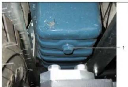
1 Macnon3nyckateJeH BnHT
Da ce noIroTBN npneMeH cbI 3a MNHmym 10 nHTpa macno.
Da ce n3KJIIOH MOTopa.
Pa3BnHTe Kanaka 3a nJIHeHa MacNo.
Da ce pa3BnE BnHTa 3a n3nyckaHe Ha MacNo.
Da ce n3nyche macnoTO.
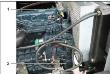
1 Kanaye 3a nbnHe He MaCno
2ФилтbpHaMacNOTOHaDbnrgateTЯ
Da ce pa3Bne MaCHeHnA FInTbp.
→ПоунстванHa мястOTо 3a NOCTABЯн И ПьтHTIte NOBbpxHOCn.
HamaKeTe C MaCIO yuTbTHHeMeTo Ha HOBnMaJIeN OHTbP npEiMoTAtka.
MOnTnpaIte HOBnMaCJIeHΦNITbP n roCTeHETeHa pKa.
3aBnIte BnHTa 3a H3nyckaHe Ha Mac- IJTO C HOBO yINbTHHeHne. BbptTMMoMeHT Ha 3aTraHa: .Nm
Da ce HantbHIM MOTOPHO MacNo. BuHa MaMACNOTO IN KOJIueCTBOTO Ha NbJIHeHE BnKTe B rnaBa TexHnueckn daHHI.
3aTbOpTeKaNaKa3aNbJIHeHaMaCNo.
OCTABeTe DnIraTeTn da pa60Tu npu- 6n.30cekyHn.
Da ce n3yaKa MHHMMy 5 MNHyTN.
Da ce npOBepn HNBOTO Ha MOTOPHOTOMACNO.
Da ce npoBepn 3a xepMeTNHOCT.
CTAPOTO Macno da ce OTBeDe IO npEdu DEHnTe 3a CEJTA MeCtA 3a Cb6puane.
NoHCTBaHe n CmHa Ha Bb3Dywnn

1ФИКСИРанe
2 Kopnyc Ha Bb3dUHHa qntTbp
306e3o nacnteJ
4ФиптbpEH n a T
5 OTBOP 3a npOdyXbaHe HaOny
OTBopeTe 6NOKnPOBkata.
→ Cbaene Kopnyca Ha Bb3dyuHnA φnTbp.
→ CbaiTeΦnTTbpHn naTPOH.
→ NocTeBbTpewHaCTpaHa Ha KOpnyca Ha Bb3DyWHnHnФJITbp.
→ CbainTe 06e3onacntenHn nblHn-TeI cAmO aKo ue 6bde cmehnH.
→ ΜΟΥΝΤΒΑΝΕ Ḁ φιπιΤβρΗΤΑ BΙΝΟΚΑ: ΜΙΤΥΝΑΝΕ ΠραχΑ Bυρχу TΤΒρή ΜΟ-BυρχΟΥCT, ΠρούγχΒαήθε ΘΤΒθTpε Ḁν-BνH C Maκε. 30 psi (2 bar) c𝑏c στβσθην Bνδλχ.
→ NObBpXHocTHa HnyNtBTHHeHTo nΦnITbPHTa BnOxKa TpI6Ba Da 6bDat HcCTn N6e3 nobpeDn 3a MoHTaxa.
→ NocTaBete NoUcTeHaTAtbPbHa BNOXKa.
Baxho: CnH0 3aMbpeHa nIIN NOBpe-DeHa qNITbPhA BNOXka Tpr6Ba da ce CMeHn.
Ako ce CMeHr qnITbPHaTa BNOJKA, CMeHete N 0e3oNacHTeHnI TblHn-TeI.
BaxHo: Pn CmHaTa Ha cnTbPHaTa BIOXKa Hs Oe3OaCteHnna NJIHNTeB HnkaBcnyaH He Tp6Ba da nona npax BbB BCMykATEHnO T-BOp.
Yka3aHue: MohmaKHa no3uua C omeOp 3a npodyxhe hadony (Bux u3o6paxeHuemo).
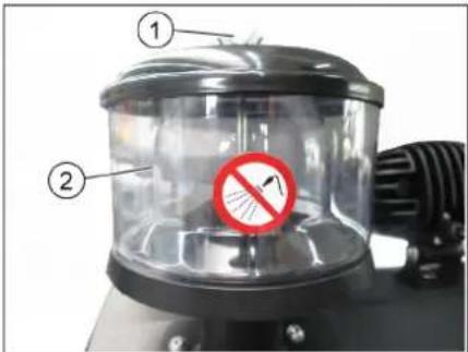
1 Kpniluata raika
2Lentpo6exhenOTdnten
Pa3BnTe KpNnTuTata raKa OT cEH-Topo6exHnOdennr.
Pa3BnTe ueHTpo6eKHHoTdeHtEn.
PpOBepKa HnBOTO Ha XnDpaBnHOTOMacNo n DonbJBAHe Ha XnDpaBnHOpMacJo
YKA3AHHE
Pe3epoapb m 3a u3memehomo He 6uea da 6bde noeduaham.
OTbopeTe kanaka Ha DnBnTaTeNa.
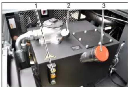
1 Macnoyka3aTeJ Ha xnpabnHOTo MACNO
2 MaHometbp
3 3aTbapu Kaak, OTBop 3a nbHe He MaCNO
PpOBepeTe HnBTo Ha XnDpaBnHnHOTo MacNo BHa6NIOdaTeHnHOTcTbKIO.
-HNBOTO Ha MacNoTo Tp6Ba Da 6bDe MeXy MapKnOpBka "MnH"- n,MAKC".
-AKO HNBOTO Ha MacNoTo e NIO MapKn-poBkata,MH",da ce DonbInn XnpaBNIuHO MaNo.
Pa3BnTe 3aTbapraunKaanKaHa OTBoppa 3a nJIHeHe Ha MacNo.
→ NouncTeTe Dnana30Ha Ha nbJIHeHe.
→ DonbHHeTe XnDpaBnMNo MacNo. BnD MaCNo: TexHmYeCKn DaHHN
3aBnTe 3aTbapraunKaNak Ha OTbopa 3aPiJIHeHaMaCNO.
YKA3AHNE
Ako MaHOMembpbm noka3ea nobuueho
HaJIa2aHe Ha xuDpaBnUHOMo MacNo,
fummbpbm 3a xuDpaEnuHo Macno
mpraea da bDe CMeHEN om cepeu3a Ha
Karcher.
IpoBepka Ha xHpaBnHaTa ype6a YKA3AHVE
Iodopbka Ha xudpaeuHama ype6a camo om cepu3a Ha Karcher.
Da ce 6Iokpa 3actonopraata cnpaKa.
CTapTnpaHe Ha MoTopa.
→ BcunxuapBnHm Mapkyu n 3BO- Dn da Ce npOBepr3 a xepMeTHNHOCT.
PpOBepKa NIOpBxKHa H BDOOxNAdTEn
Onachocm
Onachocm om uzapnne om epa nba oda! Oxadumena da ce ocmau da oxnda muHumym 20 munym.

1I3paBHTeHcBd3a aHTnФpU3
23aTbapnKaIak
→Пюверете НИВОТо Ha oxлайдаота BOДа OT ИЗразВНITEЛнЯ Кръг (HиВОHa BOДаТа МEXДу MIN u MAX.
→ NoyuCTeTe NaMeJInTe Ha oxJaNTeJIa.
PpOBepeTe MapkyuHTe Ha OXnAaNTeTnI IN 3BODN 3a XepMeTNUHOCT.
PpOBepkaHaMeTuaBaIaK
CTapTupaHa MoTopa.
→ NOBdHHeTe pe3epBoapa 3a n3MeTeHO-TOdoKpaHnOTo noJoxHeH.
Da ce H3KIOH MToTa.
a ce 6noknpa 3actonopbaaata cnpaqka.
Da ce noctabn npedna3HaTa 7aHra 3a BNCOKO n3npa3BaHe.
OTCTpaHeteJeHTteUHypoBeTeOT METAUNBAJAK.
→ 3BaTe npeDnA3HaTa 1aHa.
CTapTnpaHe Ha MoTopa.
CnyckaIte pe3epBoapa 3a n3MeTeHOTo Do KpaHOTo NIOXKeHHe.
Da ce N3KJIIOH MToTopa.
DaccecmehmMeTzuaBaJAK
Pn cnychat peepboap 3o nndy.

1 CtpaHnHa 06JIIOBka, JRCHO
2Kpnuata raKa
3 CtpaHnHo yNtBtHeHne
OTBOPeTeIaCHATACTpaHnHaO6uNBKaC KIOU.
Pa3BnHTeTe KpnuYaTne raiKn OTo 3a-DbpKaUaTaJaMaapHa Ha CtpaHnHTo yNtBHeHne n CbaIeTe 3aDpKaaUaTa JaMapHa.
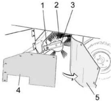
1 Bon 3a 3akpenBaHe Ha MeTnBaa
2MeTaaBnAa
3 3aKpeBbHe Ha MeT RaUaBaJIrk
4 CtpaHnUHO ynlbTHeHne Ha 3aIbpxka- uata lamapuHa
5 CtpaHnHo ynnbTHeHne
O6bpHeTe cTpaHnHTo yNtBTHHeHn HABbH.
Pa3BnIte 3akpenBaunBnHT Ha 3aKpenBAHeTO Ha METaUNBaJIK Ha-KNOHETe 3akpenBaHETo HABh.
→ CbaTeMeTAABaJAK.
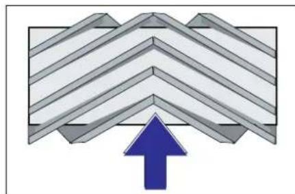
MOHTaXHO NOLOXeHne Ha MetaUINBaIaK NO NOCOKA Ha DVBIXeHNeTO (NORJIED OTROpe, Yka3aHHe: Pn MOHTaKa HA HOBMAETaLI BAIk BHMaBaTe 3a NoLOXeHNeTo Ha KOMJIeKTA qETKn C qETNaHa.
→ MoHTnpaIte HOBnMaTeaBaJIK.ΓIb6oBeTe Ha MeTuaBaJIk TpRABa DaCe NoCTaBt B ONOpITe Ha MeTuaBaJIaK Ha CpeuynOnOxHnBaIaHcnp.
Yka3aHHe: CnE MoTaxKa Ha HOBnMaTeRtU BANrK OTHOBO TpRA6Ba Da ce HAcTpOnpePfNEkTOpt 3a MeTeH.
PpOBepka HnacTpoKa Ha peΦJIeKToPa 3a MeTeHe Ha MeTuaBJIaK
PpOBepeTe HJIraHaHeTo Ha rymnte.
→ N3KJIIOUBaHe Ha CMyKaTeJIHHa YJIOBNTeJI.
→MeTaHaTa MaSiHa Da ce 3aKaapa Ha paBHO I IpaIKO MrcTO, KOeTO e NOKPnTO C npax nI IN Te6eWnp Taka, Ye da ce BnKda.
→ CnycheTe MeTuaBnAeC NoCT 3a obcnykBaHe n rO octabeTe da pa6oTt (ok.10ceK).
→ NOBUNrAHe Ha MeTua BAnK.
KapaTe ypeHa Ha 3aDenXoD.
PpOBepepepeEeKTopa3aMeTeHe.
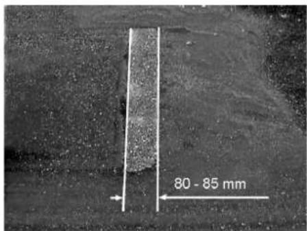
ΦopMaTaHa pePJIeKTopa 3a MeTeHe Tp6Ba da o6pa3yBa npabIneH npaBoBbINHK C wpiHa OT 80-85 MM.
HacTpoTe peΦnEkToPa 3a MeTeHe
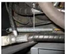
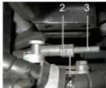
1 puyxH a
2 Raɪka 3a peryɪnpaɪne
3KoHTparaKa
4 UaHa r c pe36a
HacptoTe nIOJKeHHeTo Ha pePnEeKTopa 3a MeTeHe NocpeDCTBOM peryIpaHe Ha 60T3a HacptoKa.
→ PpOBepepepeekTopa 3a MeTeHe.
PpOBepKa n HacTpoKa Ha peFneKtopa
3a MeTeHe Ha CtpaHnUHaTa MeTna
PpOBepeTe HAnraHTo Ha rMnTe.
→ BmHHeTe MeTua BAnK n CtpaHnHata MetTa c NocToBeTe 3a ynpabNeHne.
→MetaHaTa MaunHa Da ce 3aKapa Ha paBHO IITaIKo MRCTO, KOeTO e NOKPnTO C npax INI Te6uHp Taka, He da ce BnKda.
Ioc3a06cnykBaHe CtpaHnHa Metna (3) Hanpei: CtpaHnHaTa MeTna ce cnYcka.
OCTaBete cTpaHnUHaTa MeTna da pa-60tn np6n.10 cekyHn.
→ NOBdIraHe Ha cTpaHnHTe MeTJI.
KapaiTe ypeHa Ha 3aEn xoI.
PpOBepepepepeKTopa3aMeTeHe.
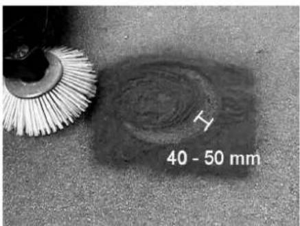
HInpoHHaHa peΦnEKeTopa 3a MeTeHe Tpa6Ba Da 6bJe MeKdy 40-50 MM.
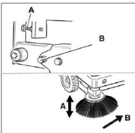
KopunpaTe peΦneKTopa 3a MeTeHe c Dbata 6oTTa 3a HactpoKa.
PpOBepepepeekTopa 3a MeTeHe.
Hacptponka Ha cTpaHnHnHte yntbTheHH
PpOBepeTe HAnraHEnoHa rymnte.
→ N3Hecete Harope pe3epBoapa 3a n3-MeTeHOTo ITO NOCDnpyte C npedna3-Hata uHaHa.
ONACHOCT
Onachocm om hapaHaehe! PpeDna3Ha ma uhaea da ce nocmae buhau npu noeduzham peepepoap 3a u3MemeHomo.
3aBbptTe npedna3HaTa 3a nIbIHO nIpa3BaHe HArpe n I NoCTaBETe B Hocaya (noCnrypeHa).
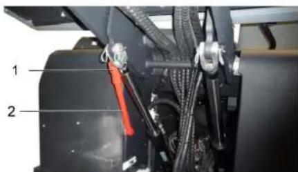
1 Hocaynpedna3Haanra
2Ппебпаизаанга
OTBOPETe cTpaHnUHaTa 06JIuOBAKaKTo e OINCAHO B rIaBa ,CMHa Ha METAUNBAJAK.
Pa3BnTe 6-Te KpNJUaTN rAkn Ha CTpaHnHaTa 3aDbpKaUa NaMapHa.
Pa3BnTe 3-Te raKn (SW 13) Ha npedHata 3aDbpxkaJ lamapina.
→PnncheCTpaHnHnTe ynlbTHHeHnI DOTOJIOBAHaDOny(HaDJIbXeHOTBOp), 3 MMdo nOda.
3aterHete 3aBpkaunTe naMapuHN.
→ NOBTOPeTe onepaunraHa npyraTa cTpaHa Ha ypeDa.
C HactoIto DeKnapnpame, Ye cHTnpaHata NO-DOy MaunHa CbOTBeTCTBa NOKUeIuN I KOHcTpkyuN, KaKTo I No HaUN HA pON3BOcTBO, PpINarAH OT HAC, HA CbOTBeTHIne OCHOHN 3NCKBaHHa 3a TEXHuecka 6e3OnaHcOCT n 6e3BpeHocT Ha DnpeKtNBte Ha EC. Pp INpOMeHN HaMaunHATA, KOnTO He Ca CbTJAcyBaHH C HAC, HACToAata DeKnapaqry Bn BaJIiNDHOCT.
IpoNyKT: MeTaHa n3cMykBaUaMaUHa ype,I, Bbpxy KOITo Ce CEiN
Tun: 1.186-145.0
HAmpaun npnloxehne DnpeKTHBn Ha EC:
2006/42/EO (+2009/127/EO)
2014/30/EC
2000/14/EO
Hamepnpnpnojxhe xapmoHn3npaHN CTaHdaptN:
EN 60335-1
EN 60335-2-72
EN 55012: 2007 + A1: 2009
EN 61000-6-2: 2005
EN 62233: 2008
PpINOxIMNaIOHaHnCTaHdApTn
一
PpHIOXeH MeToI 3a OueHka Ha CbOT-BETCTBnETO:
2000/14/EO:Прилwxкене V
HnBO Ha wym dB(A)
U3mepeH0: 100
TapaHTnpaHo: 103
IopnncBaunTe Jnca DeiCTBaT OT NMeTo V KaTO PbHOMOuNnHa ynpaBntenHn opraH.


Пьномошник NO ДOKум entaцята: S. Reiser
Alfred Kärcher SE & Co. KG
71364 Winnenden (Germany)
Tel.: +49 7195 14-0
Fax: +49 7195 14-2212
Winnenden, 2022/02/01
www.kaercher.com/REACH
Garantii
Uldised ohutusnouded
△OHT
Toode: Imur-puhkija istmega
Tüup: 1.186-145.0
Asjakohased EL direktiivid: 2006/42/EU (+2009/127/EU)
2014/30/EL
2000/14/EU
Chairman of the Board of Management

S. Reiser
Director Regulatory Affairs & Certification
71364 Winnenden (Germany)
Tel.: +49 7195 14-0
Fax: +49 7195 14-2212
Winnenden, 2022/02/01
Abi hairete korral
www.kaercher.com/REACH
Garantija
Chairman of the Board of Management
S. Reiser
Director Regulatory Affairs & Certification
Pilnvarotais sagatavot dokumentaciju:
S. Reiser
Alfred Kärcher SE & Co. KG
71364 Winnenden (Germany)
Tel.: +49 7195 14-0
Fax: +49 7195 14-2212
Winnenden, 2022/02/01
www.kaercher.com/REACH
Garantija
Chairman of the Board of Management

S. Reiser
Director Regulatory Affairs & Certification
71364 Winnenden (Germany)
Tel.: +49 7195 14-0
Fax: +49 7195 14-2212
Winnenden, 2022/02/01
| Pagalba gedimu atveju | |
| Gedimas Šalinimas | |
| Prietaisas nejsijungia | Užimkite vieta vairuotojo sédynèje, aktyvinamas kontaktinis sédynès jungiklis. |
| Jkraukite arba pakeiskite baterija | |
| Jpilkite degalu, išleiskite ora iš degalu sistemos | |
| Pakeisti degalu filtra | |
| Pakeisti pirminj degalu filtra | |
| Patikrinkite ir, jei reikia, suremontuokite degalu tiekimo sistema, movas ir jungtis | |
| Kreipkitës j „Kächer“ clientu aptarnavimo tarryba | |
| Variklis veikia netolygiai | Išvalykite oro filtra arba pakeiskite oro filtro kasetë |
| Patikrinkite ir, jei reikia, suremontuokite degalu tiekimo sistema, movas ir jungtis | |
| Kreipkitës j „Kächer“ clientu aptarnavimo tarryba | |
| Perkaito motoras lpkite aušinamojo | skysćio |
| Išplaukite aušintuvá | |
| Jtempkite trapecinés pavaros dirža | |
| Kreipkitës j „Kächer“ clientu aptarnavimo tarryba | |
| Variklis veikia, tačiu mašina va-ziuja létai arba visai nevažiujoa | Atleiskite stovějimo stabdji |
| Patikrinkite, ar néra apsvijusić juostu ir virviu. | |
| Kreipkitës j „Kächer“ clientu aptarnavimo tarryba | |
| Švilpimas hidraulinène sistemoje lpkite | hidraulinio skysćio |
| Kreipkitës j „Kächer“ clientu aptarnavimo tarryba | |
| Sepečiay nesisuka arba sukasi la-bai létai. | Akseleratorius svirtj nustatykite iki galo j priekj (aukstos apsukos). |
| Patikrinkite, ar néra apsvijusić juostu ir virviu. | |
| Kreipkitës j „Kächer“ clientu aptarnavimo tarryba | |
| Per mažai arba néra siurbimo ga-lios prie šepećio | Filtro valymas |
| Kreipkitës j „Kächer“ clientu aptarnavimo tarryba | |
| Prietaisas dulkëja Šoniniu tarpikliu | reguliavimas |
| ljunkite ortūte | |
| Išvalykite dulkić filtra | |
| Pakeiskite filtro déžës tarpiklj | |
| Kreipkitës j „Kächer“ clientu aptarnavimo tarryba | |
| Šluojami nešvarumai lieka Ištušinkite | dulkić maišelj |
| Visiškai uždarykite nešvarumu talpyklç | |
| Išvalykite dulkić filtra | |
| Pakeiskite besisukanti šepetj | |
| Nustatykite šlavimo plota | |
| Pakeiskite nešvarumu kameros sandarinamajä juostà | |
| Pašalinkite valomojo šepećio blokuotë | |
| Kreipkitës j „Kächer“ clientu aptarnavimo tarryba | |
| Nepakyla arba nenuileidžia ne-švarumu-camera | Pašalinti apsauginë atrama nuo nešvarumu talpyklos |
| Kreipkitës j „Kächer“ clientu aptarnavimo tarryba | |
| Nešvarumu kamera nesisuka arba sukasi labai létai | Kreipkitës j „Kächer“ clientu aptarnavimo tarryba |
| Hidraulíns意見 judinamu da-liu veikimo sutrikaimai | Kreipkitës j „Kächer“ clientu aptarnavimo tarryba |
Techninai duomenys
Tuck noeimpa nokpuu (MaKc.)
Toku niuomy dna oMkpa
MaKcumalbHuHaxun noeepxhi npu pyci 3 nIDhamm6yHKepom.
Y ha npymky pyx y dony- ckaembcj 3da no cxunax do 18%.
Hebe3neka nowkodxeHnHa! He npomueaume pinbmpdny dp6hzo nuny.
3araanbHi Bka3iBKN
KIO npo3nkyBaHH6yIN BnBnEHI NOKOJKeHH BiT TpaHCnOpTyBaHH, HeaHcNObictb npo ce MaarAn, De BN Kynnnpnlaad.
HaHeceHi Ha npictpi nonepeKyBaalbHi 3nakn Ta Ta6nukn daHOb BaXnBi BkazIBKn dIg Be3neHoE kcnnyaTaui npictpo.
-Pa30m i3 Bkazibkamn B ciin HcTpykuii dnaekcnnyatau cniB bpaxobyBatn 3araIbHI npabIna TexhIKi 6e3neKn Ta HOpMN dnnnonepedxehn HeuaChnx BNnAdKiB 3akoHODaBvNx opraHIB.
Bka3iBKn npn po3BaHTaxeHHI
△He6e3neuHo
He6e3neKa dny 3dopoe8'he6e3neKa yuKoDxKeHHa!
Ipu eahmaxKeHHi cnid 3eepHymu y6a2y Ha eaay npucmpoio.

m = 311
CTapi npncptoi MicTb ciHHi MaTepiAIn, 10 MoKoTy BnKOpNCTOByBaTnca NobTOpHo. Batapei, Mactnlo Ta cxoxi MaTepiAIn He NOBnHi NotpaNTu HABKOJIuHc CepeDobnue. Tomy, 6ybIaacka, yTuJI3yIte CTapi npncptoi 3a Donomoro CneiaJbHNx CNCTeM 36Opy CMTTT.
Ihctpykuii i3 3actocybaHHKOMnOHeHTiB (REACH)
AkyaIbHi BiOIMOcTI Ipo KOMnHOENTn HabeHeHHa Be6-By3JI 3a aIpecoHo: www.kaercher.com/REACH
RapaHTia
YKoKHi KpaIHi DiIOb yMOBn rapaHTi,HaDaHOI BiNIOBIDHOO φipMOH-npOdaBcEm. HenoJaKn Bpo60Ti npCtpoM mUycBaMo 6e3KoWTOH NoTPOrM TepMiHy dIraPahTI, kUO BOH BnKlnKaHI 6paKOM MaTePiAly QN NOMIKAM NROTOBHeHHa. Y BnPaNDy UHHoI rapaTIT3BepTITcbaDo npOdaBzry HnHbJInxKHy ABTopN3OBAHn CepBicHNI CEHTp 3DOKyMeHTaNbHM NiITBepDkeHHm NOkynKn.
Pn3NaueHH
MaunHa, 10 NiDmita, HapabnCmTTB63nocepEnbO B peepByap dna 36opy CMTTA.
-06epTobn BAn, 10 niDmita HappabIe CmTTI npMaB pe3epByap IJr 36opy cmTTI.
-6iHa 1KtKa iNIMiTae KyTn KpaI NOBepxHi, 0o NIMiTaeTbcra, I DOCTABNRe CMITBA3OHy pOBoTN Bana, 0o NiIMiTac.
-Дpi6Hn nIN BCMOKTyEcB CMOKTyBaIbHM BeHTnIaTOpOM Yepe3 φIbTpДЯ nIy.
PpabnIbHe 3aCTOCyBaHHa
BnKOpncTObynteIIO nIDmitaHbMyMaunHy tInbKn 3riDHO 3 IHCTpykuiio no ekcnnyataaii.
→ NpepB BnKOpNCtAHHm nepeBipTe HaJnxKn CTaH Ta 6e3NeKy npCtpoTu O6NaHaHH. KaIO O6NaHaHH 3HaXoNTbcra Y He6e3DOraHHOMy CtaHi, Ioro He MoxHa BnKOpNCTOByBaTn.
- Lc mITTe3bnpaIbHa MaunHa npn3HaueHa nIe nIIMiTahHra 3a6pydHeHnx noBepxOHb Ha Bynui.
-3a6opohraetbcraekcnnyatauaipnCTPOIOB3akpntnxnpMiuueHHX.
- Anapatn 3 cninHm 6e3 BiNIOBIDHO OCHaueHHra (BCTaHOBNIIOBaHOro Ha 3aBODi) He DOnyCKaIbTcR daIPO6OTn ByMOBax IopoxKhbO rpoxy.
Ipnctpi MoKe 6yTN BnKOpNCTaHn Ha npoiKdKnx Doporax TiIbKn nicra nonepeHbOro iHnBldyaIbHOro npnMaHH ophiinHM KOHTPOJIOUOHm OprAHOM.
-Yci KOBnakn npncToPO MOxHa BiJKnBAtu Nmue B Micux, 3axnueHnx BiDNOTpannnHHBOIN.
-3a60poHЯETbC8eKcnIyatauJpiNCTpOu DnA 360py ukiDnBOrO dny 3doPov'niNy.
-3a6oPOnHcTBcBHOCHTN3MiHN B npnIaI.
-3a60pOHHB/BCMOKTyBaHn Bv6xoh6e3neuHnx piDnH, roPouHx ra3iB, a TAKoK HEPo3BeDeHNXKcNt Ta po3HNHkIB! Ce CTocyeTbC6EH3nHy,po3piJkyBauiΦap6n TaMa3yTu, kI MoKyTu CTBOpOBaTu Bv6xoh6e3neuHi ra3n a6o cymiu, 3MiuyuChb 3i BCMOKTuBaHIM NOBITpM, a TAKOxAueToHy, Hepo3BeDeHNX KcNt Ta po3HNHkIB, ocklbKn BOH N0WkoJKyIOb MaTePiAn npNCtPO.
-He donyckatniDmitaHHBcMOKtyBaHn naiauux afo Tlioux npedmetib.
-Пистpiй пиз haueн TINbк Дя робOTи Ha NOBepxHx, 3a3haueHx y daHomy noci6Hky 3 ekCnnyatauii.
-Пилад може nepecybaTЯ TIlbkn no NOBepxHx,ДOnyueHnxДЯ BIKOPnCTaHHN NiIMiTaNbHnx MaunH KepiBHNCTBOM NIDpnpemCTBa a60 iXHIM PpeDCTaBHnKOM.
-3abopohraetbca noro 36epirahnny He6e3neuHnx Micx.3aboponeHo BnKOpncTOByBatn npncpti y Bn6yxoHe6e3NeuHX npmimiueHHX.
-ЯЗагалбправино діснachtynHe: He Donnyckatn 3iTKeHHeNpInaNy 3 JereKo3aMmCTmM peOvBnHaMn (He6e3neKa Bn6yxy/NoxkeKi).
PiiXoJaui nobepxhi
HEB63NEKA
Hebe3nka npaHenn! Nepeepumu 3amhncmb noeepxhi nepeo i30io.
-AcpaBbT
-Помисловиплоги
-CyuiJbHa(haHbHa)niIpora
- B e T o H
-БуцаТкa
OBEPEKHO
Hebe3neka yukokhenHa! He donyckamunonadaHnE npucmpiu cmpiOK, bipbo0K a6o dpomy, ockinbku eoHu MoKymb Hamomamucra Ha baI, uo NiMimaec.

A
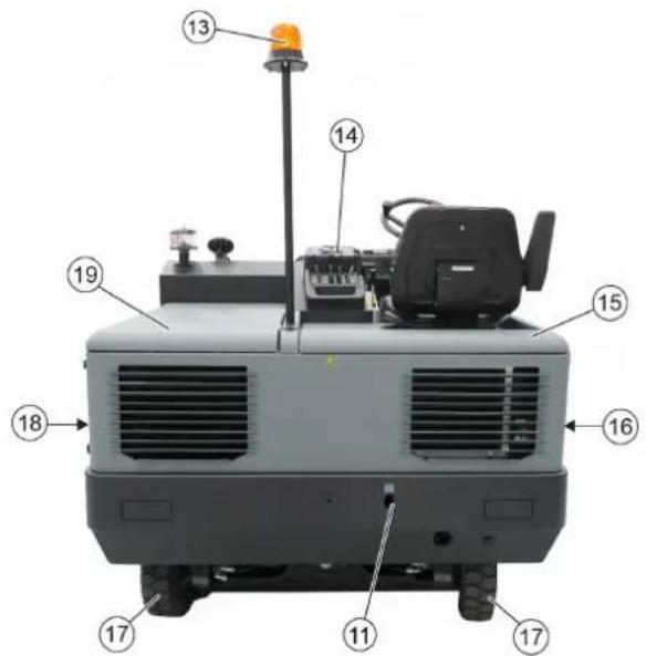
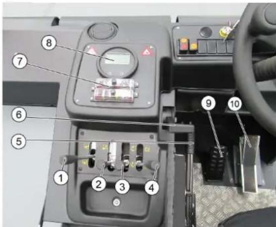
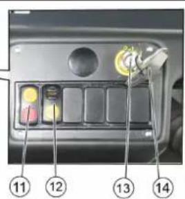
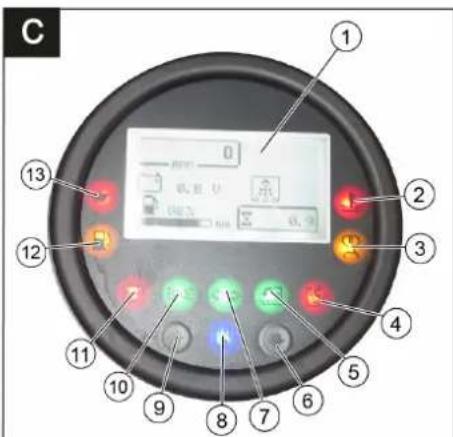
3o6paXeHHn iDmitaJIbHOI MaunH N EJeMeHTn npncToPO
MaHIOHOK A
1 Kpnska pe3epByapy
2 CnDinHHa (3 KOHTaKTHM nepemNKaayem cnDinHHa)
3 KepMoBe KoIeCo
4БLOkyBaHnK KpIuKn npicTpOo
5 Blue Spot (onzij)
6 Biüdentropobin cenapatop
7 KpnuKa npncTropo
8 BiuHi zitKn, npabopuy
9 PpeeHne Koneco
10 Bxidn OTrBip Bany, nDmitae
11 CtiKe MicCe KpInnEnHr
12 3abocbKa Ta6nUka
13Поблесков Маячok
14 ElenemEni KepyBaHHa
15 Kpuioka npictpoC npaba
16 Kpnska, npabopuy
17 NobiDne konec
18 Kpnuka, nibopyu
19 Kpnuka 3JIba (KpnuKa DnBnryHa)
MaHIOHOK
1 Baxinb KepyBaHHaIINIHdpuHoi 0iKn yBIMKHeHH/BIMKHeHH
2 Baxinb KepyBaHHpe3epByapa dnn 360py cmTTI niHimAHHa/OnyCKaHH
3 Baxil kepyBaHH 6iHnx 1itok nHimahn/OnyckaHH
4 Baxkib kepybaHHKpnuKN peepByapy eikpueaHH/3akpueaHH
5 CToHouHrraJbMa
6 PeryIIOBaJIbHIMK YIcNa oBepTIB DnRyHa IeIaJIb r3y
73a n o 6 i x Hn Kn
8 KOnTpOJIbHi iHdNkaTOpn Ta dncnnne
9пени b r a nb m
10 Pnabakcepeapota Bnepei /Ha3a
11 BIMKau Harnitaya Ta YnueHHa pinbtpa CepenHe noIOxehH:YnueHHa pinbtpa Ta Harnitay BIMK. IpeHNe noIOxehH: Harnitay yBIMK. 3aHne noIOxehH: OuueHHa pinbtpa BBIMKHeHO
12 BmMkaa 3BykoBOr cHany
13 3amok 3anaJIIOBaHHaNoJoxeHHo: DBnryH BmKHeHHI NoJoxeHHo 1:BkNIOHTn 3anaJeHHaNoJoxeHHo 2:3anyCTnTn DnYrH
14 KIIOU DOCTyny Do UINJIHDPNCHOI 1
KoHTpoJIbHI INdIkaTOpN Ta dncnnei
MaJIHOHK
1IHHaJHaDnCnJIeI
Uncno o6epTIB DnBryHa
OuHHe HnHnIbTpapakTnBHe
IotyXhictb akymjTOpHoi 6atapei
JIiHbHKpo6OuHXrDINH
IHNkaTop 6aKy
2 CnHaJIbHa IaMaIaTeMnePaTyprn BODn, 0O OxOJIOJXyE
3 KOHTpOJIbHm IInIkaTOp po3irpIbaHHa
4KoHTpObHaJAMn3aKpnToI3acnIHKe pe3epByapa 360py cmTT
5 CnHaNbHa Nama BjdkpnbAHHa 3acniHKn pe3epByapa nra 360py cmTTT
6 He 3 a H r T e
?CnHnHaJIaMnaNOKaXuKaNOBopoTIB He 3aHrTe
8 INdkaia BBIMKHeHOro BCMOKTyBaJIb-HORO BEHTNJrTopa
9 He 3 a H r T e
10 KoHTpOJIbHa JAmna po6oyoro ocBiTHe 3aHrTe
11 INIkaTOp 3apA dy aKyMyIaTopa
12 CnHaJIbHa lamma 3anacy naIINA
13 CnHaJIbHa JIaMNa TcKcY MaTIna
PpeaTkom po60tn
3aΦikCyBaTH/BiDnycTHTN CTOrHKOBe rAnbMO
BidiNyctHTnCTOaHKOBe rAInbMo,HaTNCkyoH npu cIbOMy Ha ndaIb rAInbMa.
3aepkcybaTnCTOHRKOBe raIbMo,HaTNCKyOuN npu cIbOMy Ha ndaJIbraIbMa.
IpecyBaHHn iDmitaIbHoi Maunnn 6e3 Bnachoro npBODa
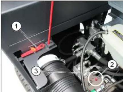
1 Cneuiabn iHcTpymeN
2 ΓΒνΗΝΤ ΣΙΑ XΟλοθότΟ XΟΥ
3IipabNiyHnHaoc
BidkpuTn koxy dxBunryHa.
→ O6epHyTn rBHT BInbHOrO xOdy (eepBOHn) riDpaBNIuHOro hAcoca Ha 180° (npOTn roDHHNKOBoi CtpiKN). BnKOpNCTOByBaTN cneuaJIbHn iHCTpyMEHT.
NOBIDOMJIENH
CneuiabHu ihcmpymeHm (peepohu 2aukoou kno) 3haxoumbc8 mpumayi Ha pami aemomobina, bina mexahi3my einbHOZO xody.
OBEPEXHO
He donyckaembcnnepecyammu mauuhy, uo niomimac Ha eenuki biocmami ma wbuwe, hix 10 km/4.
PiicnnepemiueeHHMaunHnBilbHni xi ndrapabniHoro Hacocaa nobepHyTu 3HOy Haapmy roHHKOBoi cTpiKn Do ynpoy.
IpecyBaHHn iDmitaJIbHOI MaunH3 BnaChm npuBODom
Piicn nepemiueHHMaunHn Bilbnn xi, riPabniHoro Hacoca nobepHytn 3HOB y Ha npMy roHHNKoBOi CTpiKn Do ynopy. BnkOpncTObyBaTH cneiaIbHn IHCTpy-MENT.
BVeDeHnB EeknIyatauio
3araJIbHI BkA3iBKn
→ Péné ékcnnyatauie npouHTaTn no-ciBHK 3 ekcnnyataui BpuObHnka npic-tpoIO oO6nBO npHnHTn DO yBarn Bka3iKn uOdo be3neKn.
BcTaHOBHTMaHHy, 10 NiIMiTae, HapibHn NOBepxHi.
→ BnTARHyTu KNIU 3anaJIIOBaHHa.
3aΦiKcyIe CTOrHouHy rIbMbHy CNCTeMy.
Ipebipka iTexhiue O6cnyroByaHH
Uoennno neped noaTkom eknnyatauii
→ Ipebipnti piBHeH 3aOBHeHH naIINBHORO 6aka.
→ IpebeipuPiBHeMaTnua y DnBryHi.
→IpeBipuPiBeHbOxoJIOxJyUOoi piDHH.
→ IpeBipuTn TnCK y uHax.
→ ΠepeBipNTn BAN, ΣO NiDmitae i 6iHi ΜιTiKN Ha 3HouyBaHHa HArBnICTb CTpi-OK, ΣO HAOTaJIncr.
→ Πηρεβιριτι Κολεσα Ḥα Ḍαγαθίκις Βτρι-ύΚ, ΣΟ Ḥανόματαλίσης.
→ Ipeebipntu BiueHTpOBn cenapatop Ta nobITpyHm pInbTp, npn Heo6xIdHOCTI ONUCTNTN.
→ Ipebipntn CTan Bcix enemehtib ynpabJIHH.
→ IpeBipTu npnaH ha npedMeT now-KoDxKeHb.
→ BnKoHaTn YIeHHeH φiInbTp dIa IINy 3a DOnOMOrO KHOKN YIeHHeH φiInbTp.
Bka3iBk: Doknadhiwe nVB. po3dIn "DorT Ta TexHcHe 0cbnyroByaHHa".
3axnCT BiMop03B
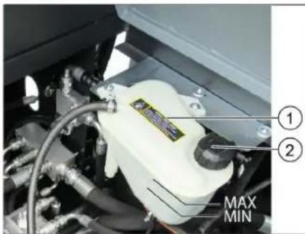
1 KomneHcauiHn 6aHok paiaTopa piHHHoro OXOJIOxKeHHA
2 3anipha kpiuka
→ Pn He63neu 3amop03ky nepeBipNTn, HIOCTaTHbO aHTNΦpN3y MiCTNbCB B BOi CNTeM N OXoJOnKeHH.
3anpaBka
△O6epeKHo!
He6e3neka 8u6yxy!
HeobxioHO uKOpucmooyamu luue mou mun naIbHo2o, 0o 3a3Haehu y ihcmpykuii 3 ekcnnyamaui.
3abopohraembca 3anpaekmauunu 3akpumux npumiueneHHx.
3a6bopohraembcnpaninHya po3ebeHn Hbiokpumoo 8o2HIO.
Cmexme 3a mum, uob nanaueo He no-nadano Ha zapayi noepxhi.
BIMKHyTN DnBuYH.
3aKpNTn 3aMKOBn npncTpipe3epByapy.
3anpaBtu du3eBHe naBHe Ppu 3oehiuHmmepeampyi Huxy6 C cnD buKOpucmoeyamu minBu 3uMo8e du3eBHe nuaue, iHaKwe uepe3 Koaynauio KOMnoHeHmie du3eBHo20 nanaea BuHukaom npoBneMu npu yedeHHi eeknnyamaui.
Bnteptn naHBO,po npnIOcnaKpTN Kpuuky 6aka.
3akpnntn klanan pe3epByapy.
Eknnnyataia
Hactpoitn noJoxeHHcNdiHHBODi
→ Notarhytn y6ik BaXinb perynboHHa cnDHH.
→ ΠepeCyHyTu CnDiHHa, BiDnyCTNTu Ba- kijb iDatu Nomy 3aΦikCyBaTncr.
→ NepemiuueHHM cnDINH BnpepHa3a/ nepeBipTu Noro pikcaio.
3anyctntnpnctpi
YBAGA
YneBumucb, uo uimku niohami.
Yci 4 baxen KepybaHHIOBUNHI 3HaXoDumucb y cepeOBmy NOJIOKeHHI.
He Hamuckamu neaB akcepepamoppa niD yac 3anycky!
→Ppucmpiu ochaueHu KOHmakmHM 6umukaem cuiHH. Ppu cmaabaHHi3 cuiHHeodj npucmpiu eiknouaemb- C
→ Picra BMUKAHRA 3anaioeahna aemomamuHOn OuyyEmbcra pInbmp dna dpibHOZnny.

1 C T O R H O U H I r a
2 PerynboBbHKn Yncna o6epTIB DnryHa
Pdabra3y
3aHHTM Mcue Ha cnDHHI onepatopa.
3aIATN CTORHOUY rAIBMY CNTeMy.
→Чис no obeptiB ДИВURA BCTAHOBUTn np6I. Ha 75% MaKcIMaJIbHOrO YcCnA o6eptiB.
BCTaBtIN KInOu B3AMOK 3aNaIeHHA.
→ ΜονερΗγι Κλίουγα 3anaλικοβαHHB nο-ποχεHHY yβιMκHEHHY 3anaλικοBAHHY (nολοχεHHI). ΜιαεJBHη Αβυγή: KoHTροJIbHη iHπι-KaTOp po3irpiBaHHa CBiTntbca.
→ 阿TINbKN KOHTpOBHm IHnKaTop po3irpiBaHH 3raChe, NOBepHyTu KInou 3anaIOBaHHy noIooKeHH II (3anyck DBnryHa) Ta TpMaTH, DOKN DBnryH He 3anyctntbca (Makc.10cekyHd).
BidiNyctntn KIOU 3anaJIIOBaHH. KIOU 3anaJIIOBaHH NOBepTaEcB NONO- XeHH I.
→ 3a Temnepatypn doBkijna HnKcye O°C Ipepe TmM kP03noaTu po6Oty, npo-rpiTn DnRyH Ha Hn3bKnx o6eptax.
Bka3iBka
YKIO DnHyH He 3anyckaTbcra, NOBTOpTN 3anyck.
PepecyBaHHHa npnpa
HE6E3NEKA
Hebe3neka Heuachux bunaokie!
Pyx 3 nioHmum 6yHkepm dJa cmim mra 3a6oPoHeHu!
△OBEPEXHO
Hebe3neka nowokjehnra!
→Ipeod noaykom pyxy afo haeahmaXeHHM Maunu duam duuyHy do-cmamhbo npoapimuc.
→ Nedanb akcenepamopacn3aekdu Hamuckyeamu obepexmo na noeinbHo. He do3eonraemcbpa i3ko 3miHoeamu Hanpym pyxy i3 aadhbozo xody Ha nepeodhi i haenaku.

1пекальгалma
2 Πeɪaɪb akceɪnepaTopa "Ipeɪdni xiD
3 Педалы akceлерatopa "Зади xi'd
→ PerynboBnK nCna oepTIBnRyHa nobHCTno nepeCyHTn Bnepei (Po-6oHe nCNO o6opotIb).
HaTnCHyTu Ta yTPmMyBaTu neaJIb raJIbMa.
Bidnyctte cToHkoBe raIbMo
→ПиавноHaTnCHyTuHaNeaIbakcepe- paTopa.
3a donomoroKePmapeyIIOBaTuHa-npymok pyxy.
iXaTHnBnepeD
→ПиаьнонхakntиВпeрдхоюByneanb.
IxatnHa3a
△HEBE3NEKA
He6e3neKa mpa8MyaehnHa!
Pioa cypxy Ha3ao He Ma6 bymu He- 6e3neku dna mpemix oci, npu nompe- 6i, npoeecmu ihcmpykmax.
→Пиавно HabkaTn Ha3aД xOdoBy neaIb.
XapakTep pyxy
3 Donomoroi nea iakcepeataopa MoKINBO 6e3cyiHacte peryIOBaHN HsBnKOcTi pyxy
BapTo yHnKaTu Pi3KOrO HaTnCKaHH neDani, TOMy 10y UcbOMy BnnaIky IrpabNiuHa CnCTema MoKe 6yTu NOnkOxKeHa.
→ Pπn πaɪnHni noTуЖиоcti πiД yac noDɔ-nAHHI niiHOMy cπiD 3MeHwHTN haTnCKaHHa Ha xOoBv neaJIb.
TalbmyBaHHy/3yInHHeHH
→ PicnB BiDnyckaHH neani pyxy npnCTpii camOctiHOrraIbMye i 3ynHReTb-Cr.
→ДЯбиьоу ranbMIBHOro epeKty a60 B ekTpeHnx BnnaKax HATNCHTN ne- daJIb raJIbMa.
IodonanHn nepekoD
YBACA
He nepeixkoxamu ueep3 npedmemu a6o He3akpinnehi nepezopodu ma He 3pyuyea-mu ix.
IIOJIAHHa HEPYXOMNX NpeuKoD BucToHO 6Inbue 70 MM:
Hepyxomi nepeukoN cnid donatn TlBkn 3 BnKOpncTaHHm BiNOBiHOI paMn.
IIOJANHHepeyoxmNnepeKoD BncoTOHO 50 MM:
→ ΠepeuKoDi cπi npoxoHn o6epeKHo,pyxaOuHcB BnepeHa nobIbHiuBnDkoCTi.
PiiMItaHH
06EPEXHO
He donyckamu enyuehn 6 Mauuhy nkyeanbHexcmpiok,dpomy u make iHwe.,momy uo ue moke npueecmu do yukodxehn Mexahi3my, uo niimimac.
Bka3iBka:ДЯ DOCAHHeHHA ONTUMaNbHOrO pe3yIbTaTy pO6ToH Heo6xIaH OPO3miprTu WBnKicTh pyxH 3MiCueBIMM yMOBaMn.
BkaibKa:ΦIbTp dIaI pyIHO rNny aTOMaTHNO OuIIaEbC KoKHi 10 XBnIH.
Pnmuitka: niuacpo6oBnB30hi3dpHMM NINOM fInbTp notpi6HO ouNsuBaTu actiwe. Dnur cbo rno nroDIOaTkoBO ouNsuBaTu fInbTp dna Dp6Horo nnHy BpyHy.
OuHcHnHn Hn Hn Hn Hn Hn Hn Hn Hn Hn Hn Hn Hn Hn Hn Hn Hn Hn Hn Hn Hn Hn Hn Hn Hn Hn Hn Hn Hn Hn Hn Hn Hn Hn Hn Hn Hn Hn Hn Hn Hn Hn Hn Hn Hn Hn Hn Hn Hn Hn Hn
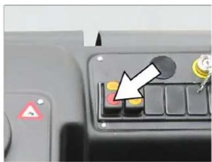
OCHNTIN pIbTp IaI pI6HOro nHy, HATCHyBUN KHOJky OHIueHHA pIbTpa.
Baxinb kepyBaHHa
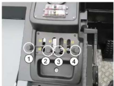
1LIniHrpUHa uTka: yBIMKHeHHn onyCKaHHn (Bnepe) / BmKHeHHn n iDiMaHHn (Ha3aD)
2 Pe3epByap IЯ 360py CmITT: onyckaHn (Bnepe) / nIhImaHa (33aNy)
3 BicHa 1tKa: onyckaHHn (Bnepei) / nI-Himahnn (Ha3aI)
4Kpnuka pe3epByapa:BidkpnbHnna (Bnepeπ)/3akpnbHnna(Ha3aπ)
PiIMiTahnCyxo iINor
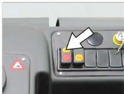
→ YbIMKHyTN HArHiTaY.
Baxinb KepyBaHHK Pnwnpe3epByap (4) Bnepei: Kpuoka pe3epByapa BiKpnaCTbcra.
PpIMrKa:Ma3acBITNTNc3eJIeHn IHINKATOp.
→Пи nIDmTaHnIO nobepxohB: Baxilb kepyBaHHaUNIHdpuHHO uTKO10(1)BnepeD:UNIHdpuHa uITKa BMKAeTBcR anyckAeTbcra.
→ПичшENHkpaIB: Baxilb KepyBaHHB 6iHnx 10K (3) Bnpeid:BiHa 1tKa onyckaetcbcra.
PiIMiTAHNBAONORoI a6o MOKpOi niDnOrn
BumkhyTuHarHiau.
Baxinb kepyBaHHKpnuKpe3epByap (4) Bnpei: KpuKa pe3epByapa BiKpnuBaCTbcra.
Pnmuitka:Ma3acBITNTNc3eJIeHn iHdkaTOp.
→Пи nIDmTaHnIO nobepxohB: Baxilb kepyBaHHa UINIHpHuHO ⅢTKOHO (1) BnepeI: UINIHdpuHa uITKa BMKAeTBcR anyckaeTbcra.
→ПичшENHkpaIB: Baxilb KepyBaHHB 6iHnx 10K (3) BnpeIe: BiHa 1tKa onyckaetcbcra.
CnopoxHHTpe3epByap nA cmTT
HE6E3NEKA
He6e3neka mpa8myaHnHa!
→Пд ус bunopoxhen8 30HI ueaHmaxenpe3epeyapy dna cMimma 3abopohembcnpe6ybaHHnmoe ma meapuH.
△HEB3NEKA
He6e3neka 3daennoeaHnra!
Hikonu He mopkamucc cucmemmu mraon mexahiHOcucmemu eunopoxhen. He cmou niid nihmum peepeyapom.
HEBE3NEKA
Hebe3neka nepekudahnra!
→Пд ус виpopхненсmaьum npu-nad ha pihi noepxhi.
YBAFA
Hebe3neka mpaM ma nowkoDxKeHb!
→Пд уac cnopoхненmoKnuepe po3no-poWeHHKaMeHie eID eana, uO Ni-d-mimac.
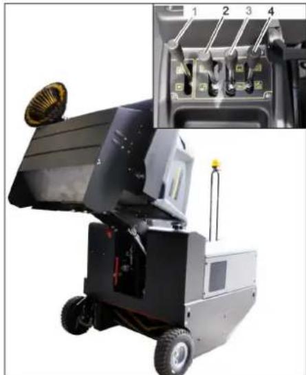
106 nHnBn, 10 niMtae, Ta 6iHi 1tKn, Baxinb KepyBaHHa (1 Ta 3) nepeBecn Ha3a.
3akntkpiukype3epByapy,Ba- kjIb kepyBaHHa(4)nepeBecTuHa3aJ. Pnmitka:Ma3acBITnncyepBOHni iHdkaTOp.
Ⅱo6 niHrTn pe3epByap dIa 360py cmITra, BaxiNb kepyBaHHpe3epByapy dIa 360py cmITra (2) nepeBecTu Ha3aI
→ Nobinbno niid'ixatn do pe3epByapy dna 360py nny.
3aΦikcynte cTOrHOHy rAInbMIBHy cnCTEmy.
Ⅲo6 BiKpnTn KpNkpype3epByapy, BaXjIb KepyBaHnK PKNk npEepByapy (4) npeBectn Bnepei cnpOxHn pe3epByap dna cmITT. PtmuTKa:Ma e 3acBtNTncr 3eJHn iHNkATop.
3akpnKpnknype3epByapy, Baxjib KepyBaHHKpnuKnpe3epByapy (4) npeBecTu Ha3aD o pfikcaii B KIN-uebOMy NIOJKeHHi. Pnmitka: Mae 3acBiTnTnCra YepBOHni iHNiKaTOP.
BiDnyCTIe cTOHKOBe raIbMo
→ NobilbHO BiTixaTN BiD pe3epByapy nIy 360py nIy.
Ⅱo6 onyctnIpe3epByap nIa 360py cmITB B KInCeBE NIOKeHHBaxKINb KepyBaHHpe3epByapa nIa 360py cmITB (2) nepeBeCTn BnepeD
BmKHyTn npncTpim
Ⅲo6 niiHnBn, Ⅲo niiMiTae, Ta 6iHi ⅢitKn, Baxinb KepyBaHHa (1 Ta 3) nepeBECTn Ha3a.
3akpnTKnpiuKpe3epByapy,BaXjIbKepyBaHH(4)nepeBecTuHa3a.
→ NobHicTIO nepeBecTeHa3aIpeRyIO-BaJIbHnK YnCnA 06eTIB DnBryHa.
→ HATNCHyTN Ta yTPMMyBAtn neaIb raIbMa.
3aφikcyte cTOrHOHy rAInbMiBHy cnCTeMy.
Knou 3anaHOBaHH NOBepHyTN B No3uio "0" i BNTaHyTN NOrO 3 aMka.
TpaHcnpotyBaHHa
△HE6E3NEKA
He6e3neKa ompumahnma ywKodKeH! Ppu mpancnpmyaehnCiid 3eepymu ybaay Ha easy npucmpoio.
→ Kliou3aapanIOBaHHn NOBepHTN BNO3uIHO "0" IBNTRHyTN NOrO 3 aMka.
3aφikcyte cTOrHOCHy rAJIbMIBHy cnCTeMy.
→ Pπpκριπην npιστρίη Σο CTικκx Mιςκβ κριπλεnhγ (4 wT) 3a ΚόπΟτού Ḁτχκην πεμεΗν, Tρος Αδο Μαυτιούνιδ.
3aΦikcyBaTn anapaT, nIDKnlaBn nIg NOrO KOleca KInHn.
→ Pn nepebe3eHHi anapaty B TpaHcnopTHnx 3acobax cnD bpaxobyBatn MicZei NiOci depkabHi HOpMn, HanpabJIeHi Ha 3axnCT BiD KOB3aHH Ta nepeKuJaHH.
36epiraHHBvBeDeHn3 ekcnnyatauii
△HESE3NEKA
He6e3neka mpaM ma nowkoJKeHb!
→Ppu 36epiaaHHi epaxoeyamau eaay npucmpoio.
→ NocTaBnTn npncTpni Ha pibHy nobepxHIO B cyXOMy Ta 3axNueHOMy BiD Mo-po3y MciCi. HakpTN dIa 3axNcTy BiD nIpy.
06 yHnKHyTN yWKoJKeHHa eTnHn, nIHn BAN, 0 niMItae, Ta 6iHi iIT- KI.
Klou3aJIIOBaHHNoBepHTN Bno3uIHO "0" IBNTRHyTH NOrO 3 aMka.
3aqiCyTe cTOrHOHy rIbMiBHy cnCTemy.
BxTN3axoDIBnPOTNMMOBINbHOrOCKOUYBaHHMaHN,0PiIMTaC.
→ Pn YekahHm Opo3iB Cnyctntu Body TnTO, 0o po3nnnaI npebpntu. HIOCTb aHTNp3y y BoDi, 0o oxoJNOJxJE.
KuMo MaunHa He BnKOpNCToBcTbC npTgrom TpNbAioro Yacy, cnId OToPm MyBaTnca HAcTyNHx BkazIBOK:
→ПОчNTMmaHnHy3cepeHnN 3OBHi.
3amHHTMOTOPHE MACTNO.
→ 3HATNI MHycoBv KneMy akymyIaTOpHOI 6bataeJI, KaIO npCTpi He 6yde BnKOpNCTOBvBaTncb DOBHe, HIX 4 TnXHi.
→ AkymyIaTOp cIaI 3apJxKaTu npu6n. KOxHi DbMaicui.
Hakpntn akymyjntop Ta 3axncTNTu BID KOPOTKOTO 3AMUKAHH.
DorjraTaTexHicHe 06cnyroByBaHHa
3araJIbHI Bka3IBK
OBEPEXHO
Hebe3neKa nowkoKeHHa! He npomueaume fInbmp dna dpioho20 nuny.
Yci KoBnaku npucmpoIO MoKHa bIDkpuaMu nuue e Micux, 3axuueHux eD nompaIIHHA EODU.
→ PEmoHTHI pO60Tu MOxTy IbPOBOuNTnCra NlIe ABTop3OBaHmN CepBicHMnCnyKbAmn a6o CneuaIacTAmyui Cpepi, kI O3HaonomJIeHi 3 ycima BaXKnBIMn npabUamN TexHkN 6e3NeKn.
→Пистpoi,ИО ВИКОPGИСТОВИТСЕ КOMМершноуВIDNOBIДНOCTIДМICUEBIXBIMOR,ПДЯготьnpOBeDEHIO nepeBIPKN 3TEXHIKI 6e3пeKIN 3riHNO VDE0701.
BcTaHOBnMaHInHy, 10 NiDiMItae, HapibHi noBepxHi.
→ KInOu 3anaIOBaHHn NOBepHyTN B nO3v UIO "0" I BNTaRHyTN NOrO 3 3aMka.
3aφikcyte cTOrHOHy rAnbMiBHy cnCTemy.
YnueHH
OSEPEXHO
He6e3neKa ywKoOKeHHr! He do3e0Iaembc yucmum npucmpiu 3 e0oHa0oUnaHa a6o cmpyMeHem Bodu niB uCokum muckom (He6e3neKa Kopomko2o 3aMukahnMa iHux nowKOKeHb).
UHnHa anapata 3cepeHHn △O6epexHo!
He6e3neKa mpaemyeaHn! Odaaune 3axuchy Macky npomu nuny i 3axuci Okjynpu.
→ PpoTePtn anapat raHyipKOIO.
O6dyTu anapat nobitpnm iD TnCKOM. UneHHAnapata 3OBHI
OuHCTHTn anapat, BKNOPNCOTByoH nIaB0BOBONORYraHcy, npocOeHy cna6kM NyxHM pO3HOM.
Bka3iBka: 3a6b0pOHHeTbcBnKOpNCtAHH arpeCnBHx MMHNX 3ac06iB.
PepioDnHicTb TexHiHoro 06cnyroByBaHHa
BkaibKa: liuNbHnK pOoQnx rOiH nOBiDOMJIe IPO MOMENT npOBeDeHHa Ocny-ROByBaHHa.
TexHicHe 06cnyroByBaHHa 3diHcHcTbCkNlIcHTOM
Bka3ibKa: Bci po60Tu 3 TexHIOHO o6cnyroByBaHHa 3 6Oky KJIeHTa NOBHNi npoBO-dNTnca KBaIipKOBaHm faxiBcEM. B paziNotpeBn B 6yNb-RAkM MOMENT MOXHa 3BepHyTncr No DonOMORY B CneuiaI3OBAhy TopROBeJIbHy opraHiauio fipMN Karcher.
UoHHeTexHneO6CyroByBaHHa:
→ IpeBipuTpiBeHb 3aOBHeHHnaJIuBHOro 6aka.
→IpeBipu npiBeHb MaTnua y DnRyH
PepebipntPiBeHb oxoJxOyooi piDnHn.
→ IpebeipuTn Tnck y uHnHaX.
→ IpebeipuBn, 10 niDmitae i 6iHyI tsTKn Ha 3HOswyBaHHa HaaBHicTb cTpiYOK, 10 HAOTaINcR.
→ Ipebeipntu Koneca Ha HaeBHictb CTpi-OK, 0o HAOTaTnCra.
→ IpebeipuBn BiueHTpOBN cenapatop Ta nobitprHn pIn Heo6xIdHOCTI ONUCTNTN.
→ IpebipuTn CTan BCix eIeMeHTiB ynpabniHn.
→ Ipebipu npuaad Ha npedmet noiKoJKeHb.
→ BnKoHaTn NnIeHnHnΦIbTpY dnnny 3a DOnOMOrO KHOKn NnIeHHnΦIbTpY.
LToNkHeBTEXHicHe 06cIyroByBaHHa:
→ IpeBipuTn nannBHH pfInbTp.
OuHCTHTN BOJAH paiaTOp.
OuHCTnTn riDpaBniHm MacJHn paiaTop.
→IpebeipuTnriDpaBniHyyctaHObky.
→ Ipebipntn piBHeh riIpaBniHoro ma-CTnna.
→IpebeipuTpiBeHraJIbMIBHOJpIJHH.
→ IpebeipuTn yuihBHOBaHbHi nlaHKn Ha 3HOseHcTB Ta npn notpe6i 3amHHTn.
IpebeipuTu i 3MaCTuTu KpuuKy peepByapy.
TexHne 06cnyroByBaHHaCTnH, 3HOuyOTbc:
3amihtb yuibbHOBaHbHI nHaHKn.
BiperynIObATn a6o 3amHHTN 6iHi yuiNbHeHH.
3amHItbA, 0nPiMItae.
3amHtB 6iH HtKn.
Bka3iBaKa: DoknaDiHie niv. po3diN "TexHiue o6cnyroByBaHHa".
TexHne 06cnyroByBaHH, 3diHcHcTbCnK6oO 06cnyroByBaHH CNOxNBAuB
O6cnyrobyBaHHy Chepe3 50 roHn po6oTn:
→ Nepu TeXHnHe 06CnyroBaHn CnID BnKoHyBaTn BiNObiDn DO φOpMyIpy TexHnHO OrnAу cepBicHoI cnYk6n.
Texhiehe oocnyrobyBaHHn nicra 250/ 500/1000/1500/2000 roHn ekcnnyatau:
TexHicHe 06cnyroBvBaHH cIiD BnKOHyBaTH BiINOBiHO Do fOpMylpTyTexHiHOrO orJycePBICHO CnyxKbN.
Bka3iBka:ДяЗбepexeHЯ npabaHa rapaHTiHne O6cnyroByBaHHBci po60tn 3 texHOrO n npoipinaKTnHoro o6cnyroByBaHH npotraom rapaHTiHoro nepiody noBHHI npoBoDnTnCBAOBHOKeHo cepBicHO cnyk6oO fipMn Karcher BiINOBiHDo 6poWypn no texHHyHomy 6cnyroByBaHHIO
PpOphiJaKTHuHi po6oTu
ПД�ROВКА:
BCTaHOBNiMaHInHy,IO NiIMiTae,HapibHnIOBepxHi.
→ KIIOU 3anaIIOBaHH NOBepHyTN B No3nIuio "0" i BNTaRHyTN NOrO 3 aMka.
3aΦiKcyIe CToHouHy rIbMiBHy CNTEmy.
3araJIbHI Bka3iBKN ⅢOIO 6e3neKn△HE6E3NEKA
Hebe3neka mpaemyeaHn? 3aekdu npu nidhamomy pe3epeyapi dna 36opy cmimma ecmahoenioeamu 3anobixhi umahau.
1 Tpmaay 3anobixhoi wtaHn
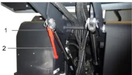
23a no 6ixHa
→ BiKHyTHn HABepx 3anO6iXHy WtAnHy DnA CnopoKHeHHN iDnHrTOpe3epBy apy i BCTaBHTn II y TpMaay (3ano6ixHn)

Будласka, He donyckaite NOtpaIIHnMOTOpHnx MaCTIN, Ma3Ty,Ди3eIbHoro NaJIINBa Ta 6eH3InHy B HABKOINHe cepedobuie.Будласka, 3axuaiTe rpyHT Ta yTuNizyTe BinpaBoBaHI MaCTIna, He 3aWKoJkyUOHy HABKOINHbOMy cepedobuity.
Bka3iBkn 3 Texhki 6e3neKn 0do akymyIaTOpIB
Ppi po6oTI 3 akymyIaTopamn cII dOtpmMyBaTnc HAcTyNHx nonepdKByBaJIbHnx Bka3iBOK:

Dompumyamuc8ekazieok Ha akymynmopi, 8 incmpyku3 Kopucmyeanhma y nocibnky 3 ekcnnyamaui npucmpoio!
Hocumu 3axucm dny ouey!

He donyckamu dimeu do enekmponimy ma akymnamopie!

Hebe3neka 8u6yxy!

3abopohembpc036eHenn 6iokpumozo 0o2HIO,ickpiHH, cmeopenhne iokpumux dxepen cimna ma naniHH!

Hebe3neka ximyuhex onikie!

Pepwa donomozaa!

InonepoKyeaJIbHe MapkyeaH-Hr!
| Уmunizаця! | |
| Pb | He bukuδamu akumyllumop y konmeiHep对不起 smimma! |
△OepeKHo!
Hebe3neka eubxy! He knacmu incmpymenu 160 nodih npedmemu ha akymyarnop, moMo Ha bubodu nonHocie, iHa 3cDhyaBbHI enememu.
△OepeKHo!
Hebe3neKa mpaemybaHn! HikOnu He noKaMa a do caunueeux enemeHmie. Ni cna pObim 3akymyarnopom Heo6xioHO noMumu pyku.
△HEB3NEKA
He6e3neKa 3a2opnHn u 6bxy!
- 3abopohembcnaHHpuo3eDeH Hbeikpum0208oHIO.
IpumiuHnry, ykOMy 3apraJkaIombc akymnyamopu, noeunHe do6pe npoeimploeamuc, momy o npu 3apraOci eudinemcbc 2a3, 0o neko bubyac.
△ObepeKHO!
He6e3neKa ximyuHux ontikie!
- Ppu enyueyhhi bpu3kig enekmponimy 6 ooi a6o ha ukipy npommu benukoio kibkicmo yucmoi bodu.
- Picna ubozo HezauHo 3eephymucdo nikapra.
Bpyduu o8a3anpaMu.
YcTaHOBHTn akymyIaTOp i nIKIOuHTN Ioro
BnHrtn akyMylTOpHy 6aTapeio
BiiKnIOUHTN noIIOCHn 3aTnCKaY BiD nOIOca (-).
BiiKnIOUHTN noIIOCHn 3aTnCKaY BiD nOIOca (+).
Nocnata TnpmaHHa dHi akmyraTropho6atapei.
→ BnHrTa n akMyJrTop 3 TpMaHa a kMyJrTopa.
BukopncTaHn aymyntop cnid ytni3yBatn BiNObiHO do dioohnx HOpM.
Ipebeipka pibH i doJIbAHn MaCTtna
△OepeKHo!
He6e3neka oniky!
→ DAtn DnBnHyH OXoNoHyTN.
→ ΠepeBipKy piBHa MaCTnHa y DbNurHyi 3diChHOBaTn IooHaMHeMeYepe35 XBUNH NiCJI BUMNKAHReDnUrHa.

1 Kpnka,OTBip nna 3aJINbMaCTnna 2 NOKaXnK pIBHa MaCTnna
→ BntaHryTu nokaxuik pibHa MaCTuna.
→ Bnteptn nokkuk i 3HOBy NOrO BCTaBNTN.
BnTyrHytn nokaxyik pibH MaCTna.
3HRTNIOKA3aHHpIBMaCTnla.
3HOBy BCTaBNTN NOKaXnK PiBHa Ma-CTnJa.
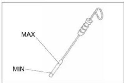
-PiBHeb MaCTnna NOBHeH nepe6yBaTm MIX BIDMTkAMN "MIN" i "MAX".
-Якpo pibeHb MaCTnla HIXKYe BiIMtKn MIN",doNTu MaCTnlo
- He 3aIbTaM MaCTnIO Bnue BiDmitkn "MAX".
Bikpytnpi3b6oby npo6ky oTbopy Dnra 3aINBkMaCTnna.
3aIHTMOTOPHEMACTINIO. BnMacna:INB.TexhiHdHi
3akpnntoTbipIaINyMaCTnna.
3aueknt npnHaMmi 5 XBnHnH.
→ IpebeipntPiBeHb MaTnna y DnBnyHi.
3amihnt B dBuryhi MaCTnno Ta fiNbtp.
△NONEPEDXEHH
He6e3nka oniky!
→Длэзamihu Momopho2o Macmuna ma φinbmpa Momopho2o Macmuna damu MaWUHIOXONOHymu, NOKU He 3HUKHe He6e3neKa onikB.
Bka3iBka
IporpiBaHHa DnBryHa nOerWyE 3NMB MToPHoro MaCTnla.
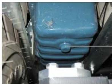
1 Hapi3Ha npo6ka mactnIO3nHBHOrO oT-Bopy
→Плготувати EMHICTbДЯЗЛВу MIMIMyM 10 nITpB MaCTnla.
→ BIMKHyTN DnHyH.
BidrBnHTmMaCTNoHAnBHy KpUkky
BnBnHTnPiO6KyMaCTNIOHaINBHO- ro OTbOpy.
3MNTMACTNIO.
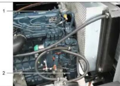
1 MactnoHAnBnKpnuKa
2ΦinbtpnMOTOPHOroMaCTnla
→ BURBHTTN MaCTINbHn φiNbTp.
→ PpoHCTnTn KpInnEHnTa yuJIbHIOBAJIbHI NOBepxHi.
→ NpeD BCTaHOBJIeHHrM 3MaCTHTn MaCTNJOM yuINbHeHHr HOBOr MOACTINb-Horo pJbtpy.
BCTaHOBHTHOBIMACTNbHNmΦInbTp Ta MiHcO 3aTgTTN.
3akpyntn npo6ky-3aarnyukdy nla 3nBy MaCTnna 3 HOBM yuiJIbHeHHM. MOMeHT 3aTAYBaHH: ...HM
3aINTMOTOPHeMaCTnIO. MapKn MaCTnT Ta pIBeH 3aNoBHeHHa 3aHaehi B rIaji "TexHiHi daHi".
3akpnTnMaCTnHOHaNBHy KpUkY.
→ДаTN nonpaцOBaTN DBIryHy npN6n3- Ho 30 cekyHd.
3auekaTu npHaMl 5 xBnJInH.
→ IpeBipu npieh MaCTnJa y DburyH
→ IpeBipuHa repMeTuHicTb.
→ IpeepaTBIIDnpaBObaHE MaCTnIOy BiNOBiHnIpyK36OpY.
UHHeHHaTa3amHaNOBITpHOrO fInbtpy

1 BLOKyBaHHa
2 Kopnyc nobitpyHoro fInbtpa
3 3anobixkHn natpon
4ΦInbtpyBaJbHn naTPOH
5 BeHTnJIaIcHm OTBip HAnpaBJeHm BH3
Bidkpntn6nokyBaHHa
→ 3HATN KOPnyc nobITpHoro fInbtpy.
3HrtnΦJIbTpbyBaIbHNnATpOH.
→ Προύηςτιν BHyTpιψιHΟ CTOPOΗ κόρηςγονπαβτρατόσο φιπήβτργ.
3anobixkHn npoH 3himatn nIwe y pa3i no 3amHN.
OuCTnTn pIbTpByaBbHn eJEMENT: Ha TBepdi NOBepxHi B6NTn NnT Ta npOdyTu CTNCHEHM NOBITpAM HA3OBHI nID TUCKOM MaKc. 30 psi (2 6ap).
→ NObepxHa yuiJIbHeHHa Ta pIbTpByaBHN eneMeH Tn BCTaHOBneHHNobHHi 6yTu nCTmTa HeuKoJKeHHMn.
BCTABHTN OUYUeHn FJIbTPyBaJIbHN eIeMeHr. BaxnBO:HaTo 3a6pydHeHn a6o nOuKOJxHeH NfIbTPyBaJIbHN eIeMENT Heo6XiDHO 3amHHTN.
y pa3i 3amHn fInbTpBaIbHoro eemeHTy 3amiHtN 3an06ixHn nATPOH. BaxnBO:Piac 3amHn fInbtpyBaIbHO eemeHTy Ta 3an06ixHoro nATPOHa nn y XoDHomy pa3i He NOBnHa IOTpanNT Do BCMOKTyBaIbHO OTBOPY.
Bka3ieKa: MoHmaxKe HnoJoxeHH - 6EHmunuuiHu omeip HanpaenHu 8Hu3 (du. manHOK).
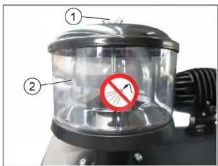
1 CmykoBa raika
2 BiDcHTpOBm cenapatop
BidBnHTmCmyKobyraKyHa BID- ceHrpoBOMcyenapaTopoBI.
OuHCTnTn BiDcHTPOBn cenapatop.
IpebipntpiBHei npabniHOro MactnTa Ta donHTu Horo IOBIOMJEHN
Pezepeyap 360py cimmn He mac 6ymu nHmui.
BidkpnTkoKxyDbnryHa.
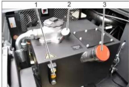
1 OINBOMIPHE cKIO dIgipabNiyHOro MaCTnla
2 MaHOMeTp
3Kpnuka,OTBipnna3aunbMactuna
→ Ipebeipu npiBHe MaTnA B rIpaBnnHn CNTeMBI ORJIOBOMy BiKHi.
-PiBHeb MaCTnla NOBHeH Ipe6yBaTm MIX BiDMITkAMN "MIN" i "MAX".
-Якpo pibeHb MacTHJa HIXKYe BiIMtKn MIN",doNTn MaCTNo.
BiiKpyTNTn KpNShky OTbOpy 3aJIb-KN MaCTnJa.
OuHCTHTn 06NaCTb 3aJIINBKN.
→ DOnuTn rIpabNiuHcHe MaCTINo. Bua Macna: nB. TexhiuHa
→ HArBnHTnKpnkky OTBopy dIy 3a-NBKMactna.
NOBIDOMJIENHRA
JaKoMaHOMemp ekayc Ha nideuueHH mucky ziopaNiuHoo Macmuna, Heo6xio Ho 3eepHymuc8 Cepeichy cnjx6y Karcher 3 numaHa 3amHu pInbmpy dna ziopaNiuHoo Macmuna.
Ipebeiptnr ridaBniHy yctaHObky IOBIDOMJEHH
Texhne 0cbny2o8ybaHHaipabNHOYcmaHoeku Ma3 3diuchouamu nuwe cepeicha cnyk6a.
3aφikcyTe cTOrHOHy rAJIbMiBHy cnCTeMy.
3anyctnTn DBnHyH.
→ IpeBipuTn iipabniHni UHaHn Ta 3'eHaHHHa repMeTuHicTB.
Ipebipka Ta o6cnyrobyBaHHB ODAHOro paiaTopa
△He6e3ne4Ho
He6e3neka ownapumucb okponom! Ppu-cmpiu nouehen ocmydumucra k MihymM 20 xunuH.

1 KomneHcauiHn 6aohK paiaTopa piHHHoro OXOJIOxKeHH
2 3anipHa KpniuKa
→ ΠepeBipuTiPiBeHBoDn, 10o oxoJIoJxUe, B KOMPeHcauiHomy 6aKy (pibeHbBOuMIX BiIMiTkamMi IMAKC).
OuNTnI nactnH padiTopa.
→ Ipebeipntu wnaHn paiaTopa Ta 3'ed-HaHHHa uinbHicTb.
Ipebipntn Ba, 0o niDmitae
3anyCTnTnBnHyH.
→Пингпpe3epByapДлЯ36opycmTTB NOHTKOBENOJOKSEHJI.
BIMKHyTN DnBuYH.
3aφikcyTe CToHouHy ralbmiBHy cnCTeMy.
BctaHOBTn 3anobixHni taHnI nIcnopoxHeHHn iDnHrTO pe3epByapy.
→ BuaNTn 3 BaJa, 10 NiMItaC, CTpiKu N MOTy3KN, 10 HAOTaJIncr.
→ BnHrTu 3aNo6ixHi uTaHn.
3anyctntn DBnryH.
Bidnyctn pe3epByap nla 360py cmitT B NOATKOBE NNOXEHH.
BIMKHyTN DBNyH.
3aHaBa, 0o nIdMaTae
3 onyuHm peepbyapom 36opy CMITT.
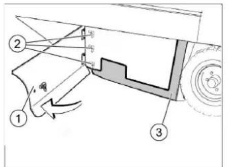
1 BiuHa 06 WnBk
2 Cmyukoba raika
3 BiyuyeuijbHenHHa
BiiKpnTn npaby 6iHy o6uWbky KIIHOEM.
→ BiDrBnHTn CmyuKoBi rain, po3a- Wobahi Ha nlocki cTOnOpHni wa6i, BiD 6iHoro yuiNbHeHH Ta 3Hrtn nlocky cTOnOpHy wai6y.
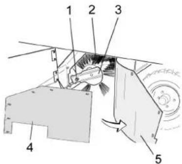
1 Kpi n n b Hn n iDmitae
2Ban, nO nIDmitae.
3 Tpmau Bany, 0o nIdmitae
MoHTyBaHH npophiIIO nIdmitaHH
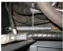
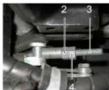
1 puyxH a
2 PernylOBaIbHa raiKa
3 K O H T P r a n Ka
4Pizb6oBn uT
BidperyIOBaTHNoJoxKeHHnpophiHIO nIMtAHN HJnxOM nepeCTaHOBKn peRyIOBaJIbHOrO TBInHTA.
→ IpeBipu nnnoHny niDmitaHH.
Ipebeipka Ta KopektyBaHH npophiJIO nIMtAHn Dn Bana, 0n NiMItac
→ IpebebipuTu TnCK y uHax.
→ПингтUninHpyHy 6iHy Uitkn 3a DONOMORO BaxenIB KepyBaHH.
→ NocTaNtMaunHy, uo NiIMiTae, HapibHy rJaKy niNory, NOKPty BUNMm wapom nny a6o meNa.
Baxinb KepyBaHH6iHnx iitok (3) Bnepe: BiHa 1tKa onyckaetbcra.
→ DAtu 6iHni uitui nonpaioBaTu 6n3b-ko 10 ceyhd.
PiHaTn 6iHi uItKn.
→ DAtn npucptpo 3aHni xi.
→ IpeBipuTn nlounHy iDmitHaHra.
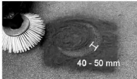
HINHa npoepiIO niIDMITAHNHOBHHACHTAHOBNTI BID 40do50MM.

BiperynIOBAtn noJoxeHHn nOocKoCTi nIdmitaHH 3a DOnOMOrO DOx peryIIOBaIbHnx TBnHTIB.
→ Ipebipn nnoounHy niMItaHHra.
BctaHOBTn 6iHi yuINbHeHHA
→ IpepeBipuTuCKyHnHax.
→ПингпН Habepx pe3epByap Дя 36opy CMITRA Ta aФikcyBatn 3a DONOMOHO 3anobixhoi tHaHn.
HEBE3NEKA
He6e3neka mpaemyeaHn7 3a8kdu npu niohmy peepeyapi dny 3b0py cmimma cmaHOJIIOBAMU 3ano6ixhi umaneu.
→ BiKHynHaBepx 3anobixhny TaHry O KdIa cnopoxHeHHn iJHrTO rpeBy- apy i BCTaBHTn II y TpMaay (3ano6ix- Hn)
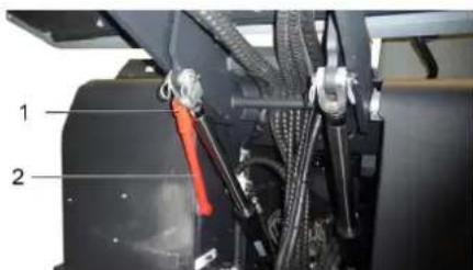
1 TpMaay 3ano6ixHoi uTaHn
23a no 6ix HA
Bikpnn 6iHy naHjb, kONcaHO B rnaBi "3aHa bany, yo niDMiTae" BN- ue.
Ocna6ntu 6cmuykoBuxraokHa6iHnPiNCKI CTONOPHiWai6i.
Ocna6ntn3raaKn(SW13)Ha nepeDHI NLOCKI CTONOPHI WAI6I.
→HaTnCKyBaTn 6iHHe yuJIbHeHHBn3 (NoobxHiOTBip),NOKI NOrO KpaJ He BnBnTBcRa H BiCTaHI 1-3 MM BiD niD-nOri.
→ PnRbHTnTn NNOCKy CTONOPHy Wai6y.
→ NIOBtopuTN nocniIDOBHICTb dIy INWOI CTOPOHn pncTPOJ.
IpeBipuTu Tnck y uHax
BCTaHOBHTMaHHy,IO NiIMiTae,HapBHH NOBepxHi.
→Πικηουγπι ΣΟΒΕΝΙΑ ΜΥΝΗ Πριστρίη έπερβίρκη τύκχην B Μυήλα.
→ IpeBipuTuTck y uHnHex, npu Heo6- xIDHOCTi, BiKOpNryBaTu TnCK.
3BedeHn npo DOnyCTmMni pIBeHb TnCKy B WInHax DnB. B po3diN "TexHiHi DaHI".
Ipebeipka/3amHa fijbtpa dna dpio6horo nny
△NONEPEDXEHH
Hebe3neKa mpaemy6aHHn!
Ipu pobomi 3 qinbmpybaJIbHO ycmahoeKOIO Hocumu macky dna 3axucmy biO nuny. Dompumyeamucn npunucnb no mexhiCi be3neku biHOcHOb obiay i3 dpibHum nuJOM.
OuHCTnTn pInbTp dIaDip6HO nny, HATNCHyBUN KONKy OunueHHaPb- Tpa.
→ CnpoKHTn pe3epByap nra 36opy cmTT.
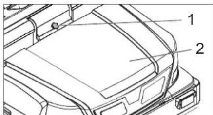
1БokyBaHnKpUuKn npucTpoH
2 KpnuKa npnctpoH
→ BiDnTn 6IokyBaHH. Dna 1b0rO He-06xHNO BiKpyTn TBnHT 3 rOJIbKOIO y BnJraI 3ipoQn.
BIDKINHyTN KPNWky npncTropoBnpeD.
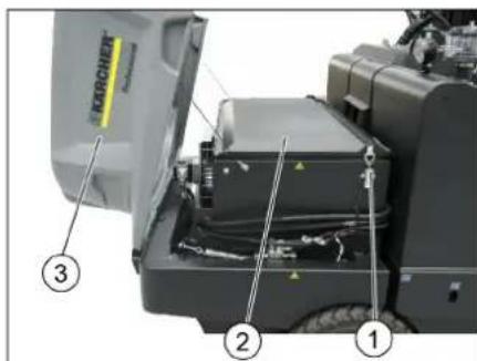
1 3amok, Kpuioka pfinbtpa (2x)
2 Kpimka pifnbtpa
3 KpnuKa npncTropo
a> H BiДКрТи КрИшky Фиьтpa.
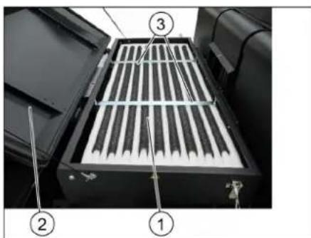
1ΦijbtpTohKOrOouHHeHH
2KpnuKaΦiNbTpa
3 NonepeHi nnaHKn
BikpnkpiuKy pInbtpa.
→ IpebeipuTn pInbTp dnnr dpioHoro nny, 3a Heo6xioHocTi oOncTu n a60 3aMiHHTn.
Bka3iBka
3amHy pfIbtpa DnA dpi6Horo nnu do- 3BOJAEBCr DopyuATn Iwne npauBHNkam cepBicHOI cnXk6n Karcher.
BcTaHOBI Ta 3aΦikCyIe KpUkky φIbTpa.
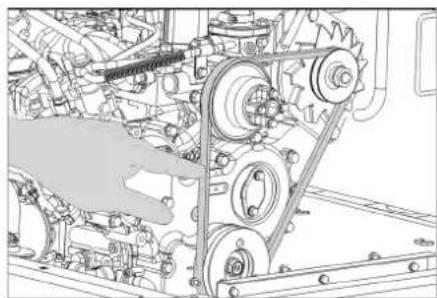
Ipebpnt Ta BiDperyIIOBaTn KINHOBN peMihb
KlnHOBN peMH npu TnCKy 10 Kr nobHHe npOBucATn 6n3bko Ha 7-9 MM.
→ HaTARHeHHKINHOBOrpeMeHBACTaHOBIOEtbcraYNOBHOBaKeHMnpaCIBHNKOMCEPBICHOIcnyx6n.
3amHHTn 3an06ixhNkN
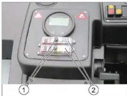
1Γaɪka 3 HacɪchkoHO
2 Kpnioka 6JOKy 3aNo6iHnKiB
→ BnKpyTnTn raNky 3 noOOBXHbOHO HAKaT-KOIO.
BikpnKpNknyHa6noi 3an06kHn- KIB.
→IpeBipu3an06HHKn.
HecnpabHI 3anobixHHNK 3amHHTN. Bka3IBKa: BnKOpNCTOByBaTN 3anO6iHKNJIe 3 ODAHKOUM 3HaueHHM.
→ IpepeBipuTu 3an06jHKn.
3actocobvbaHm MeToO uichiKu BiDnOBiHOCTi
2000/14/EC:ДОПОВЕнг_V
PibEnbnotyKHOCTIe6(A)
BmipraHn: 100
TapaHToBaHn: 103
Oco6n, HxKyne iJnncalnca, IIOJB BID IMeHt Ta 3a DOBipHeHcTIO KepiBnUcTBA.


YnoBHOBaXeHn CnIBpOgiTHNK NO BeDeHHIOKoKymHeTOO6iY:
S. Reiser
Alfred Kärcher SE & Co. KG
71364 Winnenden (Germany)
Tel.: +49 7195 14-0
Fax: +49 7195 14-2212
Winnenden, 2022/02/01
DOnomora y BInaIky HEnoJaIok
:ollo(3) aaiJai aaiSall 0s xj
JawU,aaaiwJl aWsioll
jlll oog jolll jolll aabu
.5
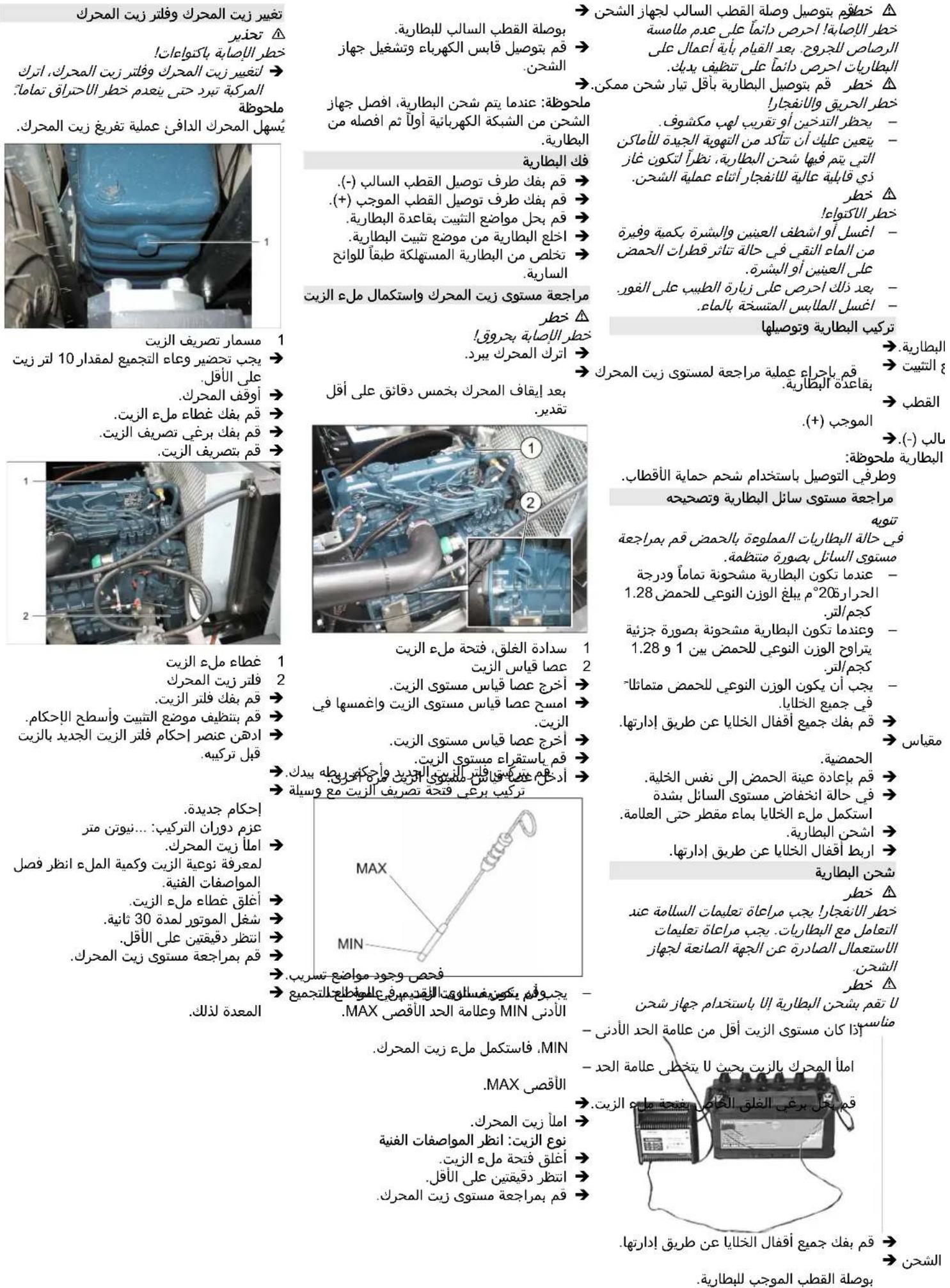
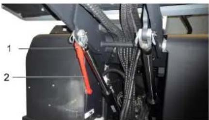
Jolol 1
2
Jollll 10000000000000000000000000000000000000000000000000
(4X) Cwllblawjgljwlj
jlu>glJgIgIwaoj>1pIaewl,
→
JJIJIJIJIJIJIJIJIJIJIJIJIJIJIJIJIJIJIJIJIJIJIJIJIJIJIJIJIJIJIJIJIJIJIJIJIJIJIJIJIJIJIJIJIJIJIJIJIJIJIJIJIJIJIJIJIJIJIJIJIJIJIJIJIJIJIJIJIJIJIJIJIJIJIJIJIJIJIJIJIJIJIJIJIJIJIJIJIJIJIJIJIJIJIJIJIJIJIJIJIJ
aalll aJrJll
U/
16 ÷
1.22 9 a loll, 2.28
"0" 00000000000000000000000000000000000000
.3gall Jg9 no a2wgl
→
J 1
→.
1
oslo 0g 13 g 913 25g 3
.aaJooaJlaJoo
j y a1g b o jai a5jll piai i 1
:ajllblblolcJra
jIgJdJIaJb
.
→
→
4 10
J 5 Jjll
Jall no lga>ajllal aasa, p9
S OBC = S ABC + S_ BOC
a|a|g a|z|
aolc
4g
- | x - 2| = 52 ; | y - 3| = 32
a//j/119
laolaloo
→
jbs) baxlll lcl clo jwglgblpwl
(5) ( x,y) = ( ab,52a)
jdlJ jqJl 1
2
o aIolal eio o/1c o>1a looll
40g 0j1b2g jdl
1
jgtaa aab gbaaal slg 1
jlll jlll l
→
jIgXll calbiui Jiaxo Juic Jglzo
algacabu slgoalpoa u albgalo
aui 1i/aioll j0jll j2
aegio oJ> UliogSj/saaalooj
aIacclj oJgU/UuSjGbC
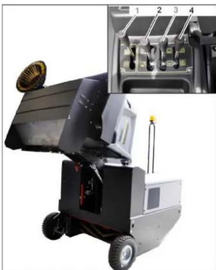
g/1g/1g/1g/1g/1g/1g/1g/1g/1g/1g/1g/1g/1g/1g/1g/1g/1g/1g/1g/1g/1g/1g/1g/1g/1g/1g/1g/1g/1g/1g/1g/1g/1g/1
glb saa aai gai gai jui>170:po 8ao aio plaxwuy ayai gaiyjui>
bbsawwio
70 1gloj jai gilg jzjglg jdzjglg jzjglg e bllp j
W
4g
yIg/llUg aouu/abwU uupe U
Jusl/ uis/ kisu j 13
aaiia aiaa aiai ie Jg2al: abglo
.ogjbl w> wll acsw aoelgo
:J 5
10
aill jllg jS aalao JaaL iic Jl 1
Ji 1000000000000000000000000000000000000000000000000000
gag acll jll jil 1
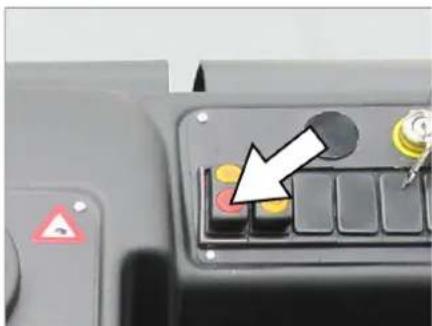
aabj jpduwul pclll jll 1
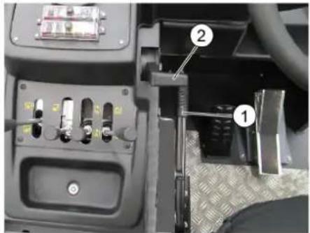
1 Jol 1
Jolal al al aol alwog 2
gll gj
. glll 2ao Jc uol>
gglal alolc bcl 20
a55 %5lc jzall clzbc
Jaaal Jao joojol 2lao
JLwUI)IgogJIcJLaWUI2lao gog .(Jaw
JgUJusssuillpssuill:Jjds
JU 100000000000000000000000000000000000000
Jzw sGgOJI L JzWUI CiaoojI
Jzal Jaa 1uUg (Jzal) 10
JJIeWUIZIaOgJJeWUIZIaOgJU
a:aa0j> a> 122, jzol cl> JaoJyll pU .aiaio
abgdo 1
1jg_011.10051_0
4 ≤ a^2
S OBC = S BOC + S_ CBA
olaill ciss oic oiai 1c0
aai
aui jaijll jiajgl gllal l jg
a//| a - 1| .c
e jg jjglwll aolj lalil b2o1 111111111111
JukelIg, aicic ic aia, polll

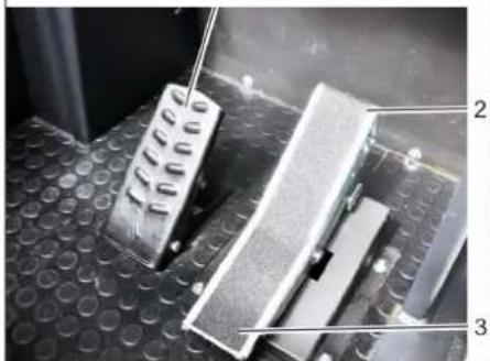
Joljll aag 1
"paU" eJwAaWg 2
"olul" 3
ploU UJall cai sae alwog J→ (Ujall cai 2c) lai
1g baiol g Joljoll awlgs lc baoi 2 abgo
all JolrJbUpa
sallalllogjJolll Jolll
.ogalll sic lagaiiui og ogell jdg
Jolie aJUaBglclUa>
JLAsiwUI
jgluulabggeo 005
aai 100
J
aill jai jbi ci wll 1e Uw:abgalo
a>allg
2021/11/20 17:43

Jiljagjg j1
2
gl|punjlll mnnnlllllll 2
- jzj 0sla
.1j11e1b6e1e1
#
jlll 1
jllllaeaalbae1jz
aaiu 9 g jj jj pi aaa all jx p9
ploW as JUJoo aeaal Cw w st
.
jglzll Jusw
a
acg,0 w/1/1/1 511
Jaeu//glj/4gau>csu
.aaalgogall
alaccl/2g9//aw/g,dcbasla/0c
1
1ic au 12aal /5ci>1 cliaa 29jo/4g2//
jgl//Juei jie/ jiu/ 2000 oJlao
sicLgogj,pcl/lljz/lld cabpu
JuwUJuw
Jz
ggloljolgrs
Jolalawgs Jc basol

Jolalawlgs Jda
Jllaui 0g jglwll aee
J
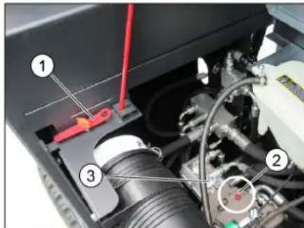
1a
2
3a
图
→
120 a5gjglll180
.(aclw)
.0ds 0e pss
Jew
- ( a + l1 1^2 + 2 2^2)
wlll wby oJull lol yogall jolgall
2
4
laicll 195 gilwll wis a c d paa
uUacugg algbolglua/lll gdi/1c
+ x = 0 去除每个
1111111111111111111111111
a aaa
aclll aolj s
l_原点 : y = - 9x
Jc slaell Ugulu uis a c
aJJIJIJIJIJIJIJIJIJIJIJIJIJIJIJIJIJIJIJIJIJIJIJIJIJIJIJIJIJIJIJIJIJIJIJIJIJIJIJIJIJIJIJIJIJIJIJIJIJIJIJIJIJIJIJIJIJIJIJIJIJIJIJIJIJIJIJIJIJIJIJIJIJIJIJIJIJIJIJIJIJIJIJIJIJIJIJIJIJIJIJIJIJIJIJIJIJIJIJIJIJ
oJouU Ugog Jauuugjuaa
jraa aclll jlacolj s
- g : l ≤ 0
a05 05 p2xu1
#
aolc|d|w]
Jzjll Jd oelg jzj
ololgogjzallaaasjlln
.1JU|JdJdJd
aigua aioj Ic uuSJI aJg Jp
JrJrJrJrJrJrJrJrJrJr
Jolj 2
aillg jazll Jlaoi
Jj
gglj>eJgssgge>
jJ2011 jSgmo a>1
aIgJfJgAolUgAL gAL gJgJgALUgAL UgALUgALUgALUgALUgALUgALUgALUgALUgALUgALUgALUgALUgALUgALUgALUgALUgALUgALUgALUgALUgALUgALUgALUgALUgALUgALUgALUgALUgALUgALUgALUgALUgALUgALU
(REACH) JgJgJgJgJgJgJgJgJgJgJgJgJgJgJgJgJgJgJgJgJgJgJgJgJgJgJgJgJgJgJgJgJgJgJgJgJgJgJgJgJgJgJgJgJgJgJgJgJgJgJg
laai
Register your product and benefit from many advantages.
www.kaercher.com/welcome ★★★★★
Rate your product and tell us your opinion.
www.kaercher.com/dealersearch
Alfred Kärcher SE & Co. KG
Alfred-Karcher-Str. 28-40
71364 Winnenden (Germany)