
KM 170600 R D Classic - Sweeper Kärcher - Free user manual and instructions
Find the device manual for free KM 170600 R D Classic Kärcher in PDF.
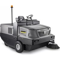



| Product type | Ride-on sweeper with seated operator |
| Brand | Kärcher |
| Model | KM 170600 R D Classic |
| Dimensions (L × W × H) | 2742 × 1904 × 2213 mm |
| Empty weight | 1 695 kg |
| Total permissible weight | 2 701 kg |
| Power supply | 4-stroke diesel engine Kubota V1505 (E4B), 1 498 cm³, 18.5 kW (24.8 PS) at 2 300 rpm |
| Fuel tank capacity | 26 L (diesel) |
| Battery | 12 V, 72 Ah |
| Maximum speed (forward and reverse) | 14 km/h |
| Maximum gradient (direction of travel) | 18 % |
| Maximum lateral gradient | 10 % |
| Sweeping width (without / with 1 / with 2 side brushes) | 1 344 mm / 1 700 mm / 2 000 mm |
| Max. sweeping capacity | 28 000 m²/h (with 2 side brushes) |
| Dust bin volume | 600 L |
| Bin discharge height | 1 540 mm |
| Rotary brush diameter | 400 mm |
| Side brush diameter | 650 mm |
| Filter area (fine dust filter) | 9.1 m² |
| Brakes | Mechanical (front wheels) + hydrostatic (rear wheel) |
| Tire pressure (front and rear) | 8 bar |
| Maintenance | Daily: check levels, tire pressure, filter cleanliness; weekly: clean radiator, check hydraulic oil; maintenance by authorized service center according to operating hours |
| Spare parts and repairability | Original Kärcher parts available; repairs by authorized service center; warranty according to country conditions |
| Safety | Parking brake, seat safety contact, ignition key, rollover protection (slopes), automatic engine stop if driver leaves seat |
| General information | Outdoor use only; do not use in explosive atmosphere or to vacuum flammable liquids; road traffic approval depending on option |
Frequently Asked Questions - KM 170600 R D Classic Kärcher
User questions about KM 170600 R D Classic Kärcher
0 question about this device. Answer the ones you know or ask your own.
Ask a new question about this device
Download the instructions for your Sweeper in PDF format for free! Find your manual KM 170600 R D Classic - Kärcher and take your electronic device back in hand. On this page are published all the documents necessary for the use of your device. KM 170600 R D Classic by Kärcher.
USER MANUAL KM 170600 R D Classic Kärcher
Chairman of the Board of Management

S. Reiser
Director Regulatory Affairs & Certification
71364 Winnenden (Germany)
Tel.: +49 7195 14-0
Fax: +49 7195 14-2212
Winnenden, 2022/02/01
Please read and comply with these original instructions prior
to the initial operation of your appliance and store them for later use or subsequent owners.
Contents
Contents EN 1
Safety instructions EN 1
Symbols in the operating instructions EN 1
Symbols on the machine EN 1
General notes . EN 1
Environmental protection. . . . . EN 2
Warranty. EN 2
Function. EN 2
Proper use. EN 2
Suitable surfaces . EN 2
Operating and Functional Elements. EN 3
Illustration of sweeper.. EN 3
Operating elements . . . EN 3
Before Startup EN 4
Lock/ release parking brake EN 4
Moving sweeper without engaging self-propulsion . . EN 4
Moving sweeper by engaging self-propulsion . EN 4
gaging self-propulsion . . EN 4
Moving the sweeper by engaging
self-propulsion. EN 4
Start up EN 4
General notes EN 4
Inspection and maintenance
work EN4
Operation. EN 4
Adjusting driver's seat . . EN 4
Starting the machine . . . EN 4
Drive the machine . EN 5
Sweeping mode . EN 5
Emptying waste container EN 5
Turn off the appliance . . EN 6
Transport EN6
Storage/decommissioning . . . EN 6
Care and maintenance . EN 6
General notes EN 6
Cleaning. EN 6
Maintenance intervals. EN 6
Maintenance Works. EN 7
EU Declaration of Conformity. EN 11
Declaration of Conformity. EN 11
Troubleshooting. EN 12
Technical specifications. EN 13
Safety instructions

Risk of hearing impairment.
Wear ear-protection aids.
Symbols in the operating instructions
DANGER
Immediate danger that can cause severe injury or even death.
WARNING
Possible hazardous situation that could lead to severe injury or even death.
CAUTION
Possible hazardous situation that could lead to mild injury to persons or damage to property.
Symbols on the machine General notes
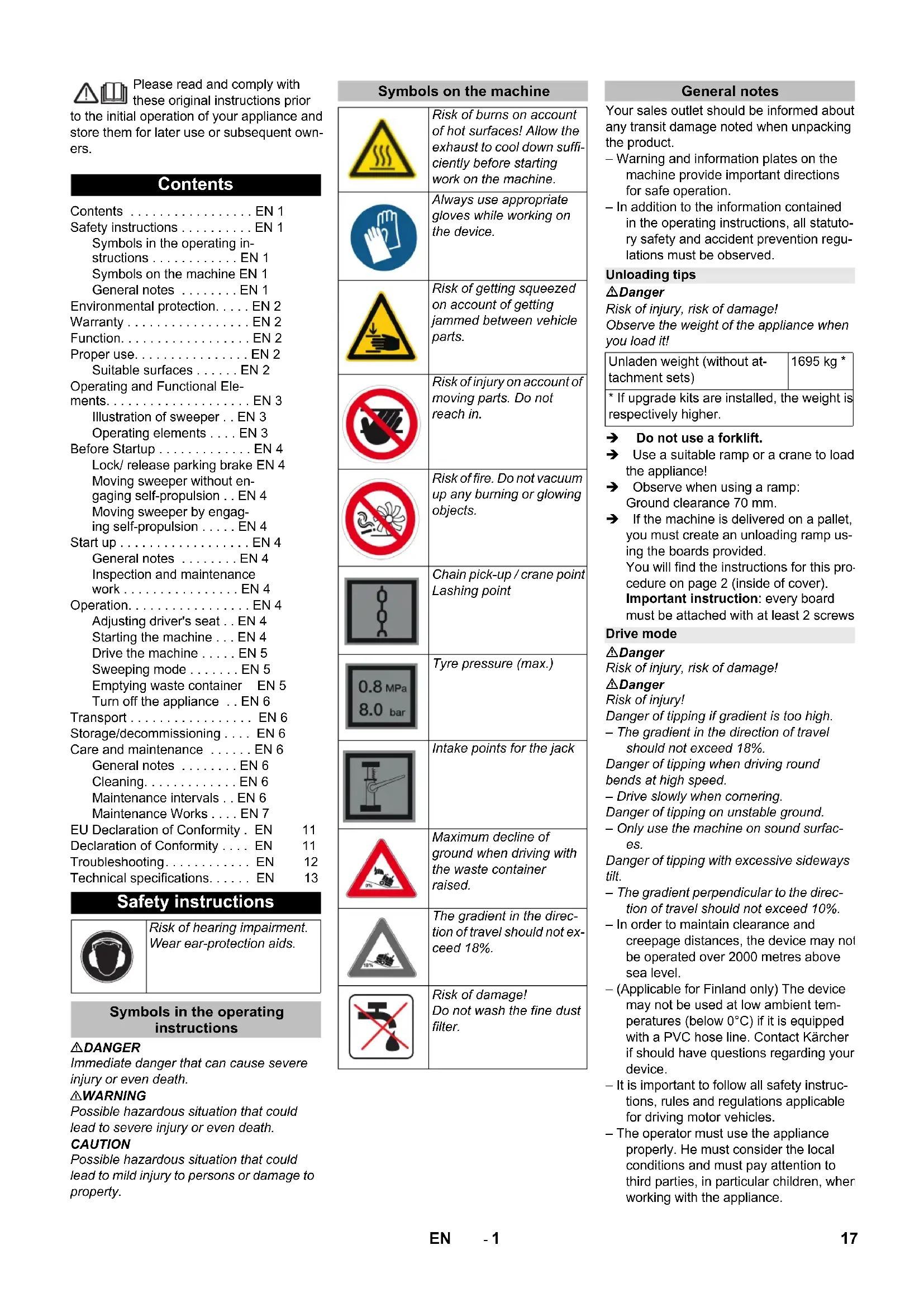
| Risk of burns on account of hot surfaces! Allow the exhaust to cool down sufficiently before starting work on the machine. | |
| Always use appropriate gloves while working on the device. | |
| Risk of getting squeezed on account of getting jammed between vehicle parts. | |
| Risk of injury on account of moving parts. Do not reach in. | |
| Risk of fire. Do not vacuum up any burning or glowing objects. | |
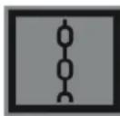
| Chain pick-up / crane point Lashing point | |
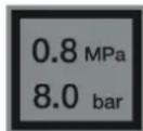
| Tyre pressure (max.) | |
| Intake points for the jack | |
| Maximum decline of ground when driving with the waste container raised. | |
| The gradient in the direction of travel should not exceed 18%. | |
| Risk of damage! Do not wash the fine dust filter. |
Your sales outlet should be informed about any transit damage noted when unpacking the product.
- Warning and information plates on the machine provide important directions for safe operation.
- In addition to the information contained in the operating instructions, all statutory safety and accident prevention regulations must be observed.
Unloading tips
DANGER
Risk of injury, risk of damage!
Observe the weight of the appliance when you load it!
| Unladen weight (without attachment sets) | 1695 kg * |
| * If upgrade kits are installed, the weight is respectively higher. | |
Do not use a forklift.
Use a suitable ramp or a crane to load the appliance! Observe when using a ramp:
Ground clearance 70 mm
If the machine is delivered on a pallet, you must create an unloading ramp using the boards provided.
You will find the instructions for this procedure on page 2 (inside of cover). Important instruction: every board must be attached with at least 2 screws.
Drive mode
Danger
Risk of injury, risk of damage!
Danger
Risk of injury!
Danger of tipping if gradient is too high.
The gradient in the direction of travel should not exceed 18%. Danger of tipping when driving round bends at high speed. - Drive slowly when cornering. Danger of tipping on unstable ground. - Only use the machine on sound surfaces. Danger of tipping with excessive sideways tilt. The gradient perpendicular to the direction of travel should not exceed 10%. In order to maintain clearance and creepage distances, the device may not be operated over 2000 metres above sea level. - (Applicable for Finland only) The device may not be used at low ambient temperatures (below 0°C) if it is equipped with a PVC hose line. Contact Kärcher if should have questions regarding your device. - It is important to follow all safety instructions, rules and regulations applicable for driving motor vehicles. - The operator must use the appliance properly. He must consider the local conditions and must pay attention to third parties, in particular children, when working with the appliance.
- The appliance may only be used by persons who have been instructed in handling the appliance or have proven qualification and expertise in operating the appliance or have been explicitly assigned the task of handling the appliance.
- The appliance must not be operated by children, young persons or persons who have not been instructed accordingly.
- It is strictly prohibited to take co-passengers.
- Ride-on appliances may only be started after the operator has occupied the driver's seat. Please remove the ignition key, when not in use, to avoid unauthorised use of the appliance. Never leave the machine unattended so long as the engine is running. The operator may leave the appliance only when the engine has come to a standstill, the appliance has been protected against accidental movement, if necessary, by applying the immobilization brake and the ignition key has been removed.
Appliances with combustion engine
Danger
Risk of injury! - Do not close the exhaust. - Do not bend over the exhaust or touch it (risk of burns). - Do not touch the drive motor (risk of burns). - Exhaust gases are poisonous and hazardous to health, do not inhale them. - The engine requires approx. 3-4 seconds to come to a standstill once it has been switched off. During this time, stay well clear of the working area.
Machines with driver cabin
- In emergencies, destroy the windows with a hammer.
NOTICE
The emergency hammer is located in the foot area, underneath the driver seat.
Accessories and Spare Parts
- Only use accessories and spare parts which have been approved by the manufacturer. The exclusive use of original accessories and original spare parts ensures that the appliance can be operated safely and trouble free.
- For additional information about spare parts, please go to the Service section at www.kaercher.com.
Environmental protection
| The packaging material can be recycled. Please do not throw the packaging material into household waste; please send it for recycling. | |
| Old appliances contain valuable materials that can be recycled; these should be sent for recycling. Batteries, oil, and similar substances must not enter the environment. Please dispose of your old appliances using appropriate collection systems. |
Notes about the ingredients (REACH)
You will find current information about the ingredients at:
www.kaercher.com/REACH
Warranty
The warranty terms published by the relevant sales company are applicable in each country. We will repair potential failures of your appliance within the warranty period free of charge, provided that such failure is caused by faulty material or defects in manufacturing. In the event of a warranty claim please contact your dealer or the nearest authorized Customer Service center. Please submit the proof of purchase.
Function
The sweeper operates using the sweepshovel principle.
- The rotating roller brush moves the dirt directly into the waste container.
- The side brush cleans the corners and edges of the surface and moves dirt and debris into the path of the roller brush.
- The fine dust is sucked in via the dust filter through the suction blower.
Proper use
Use this sweeper only as directed in these operating instructions.
The machine with working equipment must be checked to ensure that it is in proper working order and is operating safely prior to use. Otherwise, the appliance must not be used. - This sweeper has been designed to sweep dirt and debris from outdoor surfaces. - The appliance should not be used in closed rooms. - Ride-on machines that are not equipped with the proper equipment (option ex factory) are not approved for public transport. - The appliance can be used on public roads only after an individual acceptance by an official regulatory body. - All device hoods may only be opened in water-protected areas. - The machine is not suitable for vacuuming dust which endangers health. - The machine may not be modified. - Never vacuum up explosive liquids, combustible gases or undiluted acids and solvents. This includes petrol, paint thinner or heating oil which can generate explosive fumes or mixtures upon contact with the suction air. Acetone, undiluted acids and solvents must also be avoided as they can harm the materials on the machine. - Do not sweep/vacuum up any burning or glowing objects. - The machine is only suitable for use on the types of surfaces specified in the operating instructions. - The machine may only be operated on the surfaces approved by the company or its authorised representatives. - The machine may not be used or stored in hazardous areas. It is not allowed to use the appliance in hazardous locations. - The following applies in general: Keep highly-flammable substances away from the appliance (danger of explosion/fire).
Suitable surfaces
△DANGER
Risk of injury! Verify the stability of the ground prior to driving on it.
Asphalt - Industrial floor - Sealed Concrete - Paving stones
CAUTION
Risk of damage! Do not sweep up straps, strings or wires as these may wrap around the brush roller.
Operating and Functional Elements
A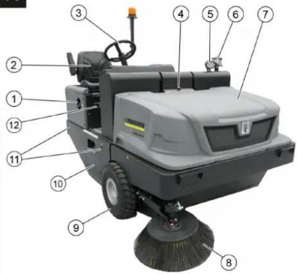
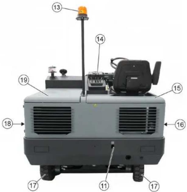
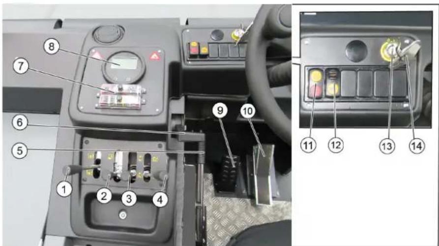
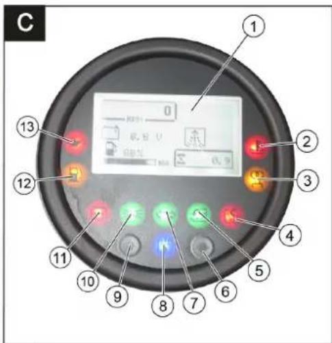
Illustration of sweeper Operating elements
Illustration A
1 Reservoir cover 2 Seat (with seat contact switch) 3 Steering wheel 4 Lock of appliance hood 5 Blue Spot (optional) 6 Centrifugal separator 7 Cover 8 Side brush, right 9 Front wheel 10 Roller brush access 11 Lashing point 12 Nameplate 13 Beacon lamp 14 Control elements 15 Appliance cover right side 16 Cover, right 17 Drive wheel 18 Cover, left 19 Bonnet left side (engine bonnet)
Illustration 3
1 Roller brush control lever On/Off 2 Control lever waste container raise / lower 3 Control lever side brush raise / lower 4 Control lever container flap open/close 5 Parking brake 6 Motor speed adjustment Gas lever 7 Fuses 8 Indicator lamps and display 9 Brake pedal 10 Accelerator pedal forward / reverse 11 Switch blower and filter cleaning Position centred: Filter cleaning and blower off Front position: Blower on Rear position: Filter cleaning On 12 Horn switch 13 Ignition lock Position 0: Switch off engine Position 1: Ignition on Position 2: Start the engine 14 Key for roller brush access
Indicator lamps and display
Illustration
1 Display Motor speed Filter cleaning active Battery capacity Operating hour counter Tank indicator 2 Cooling water temperature warning lamp 3 Preglow indicator light 4 Indicator light for closed waste container-flap 5 Warning light for open waste container flap 6 not assigned 7 Indicator lamp for direction indicator not assigned 8 Suction fan display on 9 not assigned 10 Working light indicator light not assigned 11 Battery control lamp 12 Warning lamp fuel reserve 13 Oil pressure warning lamp
Before Startup
Lock/ release parking brake
Loosen parking brake; press brake pedal at the same time. Activate the parking brake; press brake pedal at the same time.
Moving sweeper without engaging self-propulsion
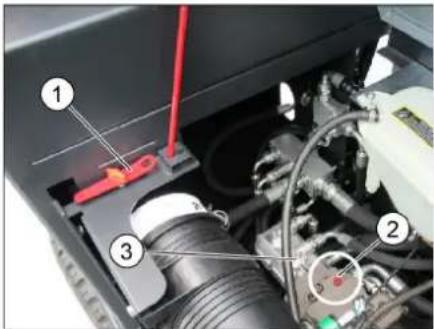
1 Special tool 2 Screw for freewheeling 3 Hydraulic pump Open engine cover. Turn the screw for freewheel (red) of the hydraulic pump by 180 degrees (anti-clockwise).
Use special tools.
NOTICE
The special tool (red screwdriver) is located in a holder in the vehicle frame, next to the freewheel.
CAUTION
Do not move the machine for long distances without engaging self-propulsion; a speed of 10 km/h should not be exceeded.
Turn back the freewheel of the hydraulic pump in a clockwise direction up to the stop after moving the machine.
Moving sweeper by engaging self-propulsion
Turn back the freewheel of the hydraulic pump in a clockwise direction up to the stop after moving the machine. Use special tools.
Start up
General notes
Read the operating instructions of the engine manufacturer before start-up and follow the safety instructions carefully. Park the sweeper on an even surface. Remove ignition key. Lock parking brake.
Inspection and maintenance work
Daily before starting operations
Check fill level of fuel tank. Check engine oil level. Check cooler water level. Check tyre pressure. Check the sweeping roller and the side brush for wear and wrapped belts. Check the wheels for tied up belts. Check the centrifugal separator and the air filter, clean if required. Check function of all operator control elements. Check appliance for damages. Clean the dust filter with the filter cleaning button.
Note: For description, see section on Care and maintenance.
Frost protection
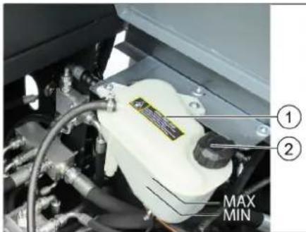
1 Coolant expansion tank 2 Closing head If frost is expected, check whether there is enough anti-frosting agent in the cooling water.
Refuelling
Danger
Risk of explosion! - Only use the fuels specified in the Operations Manual. - Do not refuel the machine in enclosed spaces. Smoking and naked flames are strictly prohibited. - Ensure that no fuel reaches hot open surfaces. Switch off engine. Open the tank lock. Fill in diesel. Below exterior temperatures of 6°C, only Winter diesel must be used, as there might be problems with operation due to the flocking of diesel components. Wipe off any spilt fuel and close fuel filler cap. Close the tank door.
Operation
Adjusting driver's seat
Pull seat adjustment lever outwards. Slide seat, release lever and lock in place. Check that the seat is properly locked in position by attempting to move it backwards and forwards.
Starting the machine
ATTENTION
Ensure that the brushes are raised up. All four control levers must be in middle position. Do not press the accelerator pedal when starting up! The machine is equipped with a seat contact switch. If the driver's seat is vacated, the machine is switched off. The fine dust filter is automatically cleaned when the ignition is switched on.
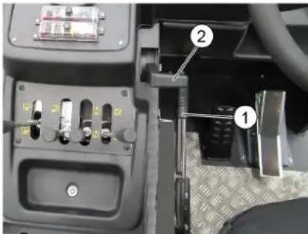
1 Parking brake 2 Motor speed adjustment Gas lever. Sit on the driver's seat. Activate parking brake. Set motor speed to approx. 75% of the maximum speed. Insert the ignition key into the ignition switch. Turn the ignition key to ignition on (position I). Diesel motor: The preglow indicator light lights up. If the preglow indicator light goes out, turn the ignition key to Position II (Start motor) and hold it until the motor has started (max. 10 seconds). Release the ignition key. The ignition key turns to position I. At ambient temperatures below 0°C: Allow the motor to warm up at a low motor speed before beginning work.
Note
If the motor does not start, repeat the startup process.
Drive the machine
DANGER
Risk of accident!
It is prohibited to drive with the waste container raised!
CAUTION
Risk of damage!
Let the motor warm up sufficiently prior to driving or loading the vehicle. Always press the accelerator pedal carefully and slowly. Do not jerkily change from reverse to forward drive or vice versa.
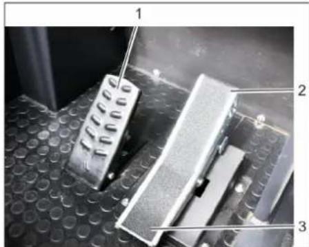
1 Brake pedal
2 Accelerator pedal, "forwards" 3 Accelerator pedal, "reverse"
Push the motor speed adjustment all the way to the front (operating speed). Press brake pedal and keep it depressed. → Release parking brake. → Press accelerator pedal down slowly. → Control the driving direction with the steering wheel.
Drive forward
Press slowly the accelerator pedal "forward".
Reverse drive
△DANGER
Risk of injury!
When reversing, there must not be any risk for third parties, have somebody marshal the driver if necessary. → Press slowly the accelerator pedal "reverse".
Driving method
The accelerator pedal can be used to vary the driving speed infinitely. → Avoid sudden operation of the pedal as this may damage the hydraulic system. In the event of power loss on inclined surfaces, slightly reduce the pressure on the accelerator pedal.
Braking / stopping
Release the drive pedal, the machine brakes automatically and stops. For a stronger braking effect or in case of an emergency, actuate the brake pedal.
Driving over obstacles
ATTENTION
Objects or loose obstacles may not be run over or pushed. Driving over fixed obstacles which are more than 70 mm high:
Stationary obstacles may be driven over only when a suitable ramp is used. Driving over fixed obstacles which are 70 mm high or less: Drive forwards slowly and carefully.
Sweeping mode
CAUTION
Do not sweep up packing strips, wire or similar objects as this may damage the sweeping mechanism.
Note: To achieve an optimum cleaning result, the driving speed should be adjusted to take specific situations into account. Note: The fine dust filter is automatically cleaned every 10 minutes. Note: When working frequently in the fine dust area, the filter must be cleaned more often. This means manually cleaning the fine dust filter from time to time.
Cleaning the fine dust filter manually
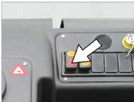
Clean the fine dust filter with the filter cleaning button.
Control lever
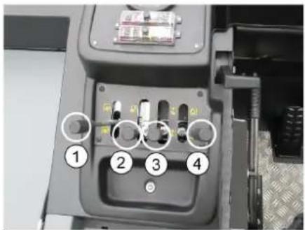
1 Switch on and lower roller brush (to the front)/switch off and raise (to the rear) 2 Lower the waste container (to the front)/ raise (to the rear) 3 Lower side brushes (to the front)/raise (to the rear) 4 Open container flap (to the front)/close (to the rear)
Sweeping dry floors
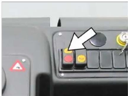
Switch on the blower. Move the container flap control lever (4) forward: the container flap opens. Note: the green indicator lamp must light up. For surface cleaning: move the roller brush control lever (1) forward: the roller brush switches on and lowers. For cleaning side edges: move the side brush control lever (3) forward: the side brush lowers.
Sweeping damp or wet floors
Switch off the blower. Move the container flap control lever (4) forward: the container flap opens. Note: the green indicator lamp must light up. For surface cleaning: move the roller brush control lever (1) forward: the roller brush switches on and lowers. For cleaning side edges: move the side brush control lever (3) forward: the side brush lowers.
Emptying waste container
DANGER
Risk of injury!
During the emptying process, persons and animals must not stay within the swivelling range of the waste container.
DANGER
Risk of crushing!
Never reach into the rod assembly for the drainage mechanism. Do not stay under the raised container.
DANGER
Danger of tipping!
Place the device on an even surface during the emptying process.
CAUTION
Risk of personal injury or damage! Stones may be catapulted off by the rotating roller brush during the emptying process.
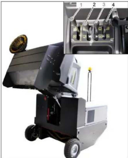
Raise the roller brush and side brush by means of the control levers. To do so, pull the control levers (1 and 3) to the back. Then close the container flap by moving the control lever (4) to the back.
Note: The red indicator lamp must light up.
Raise the container flap by moving the waste container control lever (2) to the back. Slowly drive towards the collection container. Lock the parking brake. Open the container flap by pushing the container flap operating lever (4) to the front and empty the waste container.
Note: The green indicator lamp must light up.
Close the container flap by pushing the container flap operating lever (4) to the back until it is tipped inwards in the end position. Note: The red indicator lamp must light up. Release the parking brake. Drive the collection container away slowly. Lower the waste container into the end position by moving the waste container control lever (2) to the front.
Turn off the appliance
Raise the roller brush and side brush by means of the control levers. To do so, pull the control levers (1 and 3) to the back. Close the container flap by moving the control lever (4) to the back. Pull the motor speed adjustment all the way to the back. Press the brake pedal and keep it depressed. Lock the parking brake. Turn the ignition key to "0" and remove it.
Transport
DANGER
Risk of injury and damage! Observe the weight of the appliance when you transport it.
Turn the ignition key to "0" and remove it. Lock the parking brake. Secure the appliance at the lashing points (4x) using tension belts, ropes or chains. Secure the wheels of the machine with wheel chocks. When transporting in vehicles, secure the appliance according to the guidelines from slipping and tipping over.
Storage/decommissioning
DANGER
Risk of personal injury or damage!
Consider the weight of the appliance when storing it. Park the device on a level surface in a dry, frost protected area. Protect it against dust by means of covering material. Raise the roller brush and the side brushes to prevent the bristles from being damaged. Turn the ignition key to "0" and remove it. Lock the parking brake. Lock the sweeper to ensure that it does not roll off. Drain off the cooling water if frost is expected and check whether there is adequate anti-frosting agent.
If the vehicle is not used for a longer period of time, observe the following points:
Clean the inside and outside of the vehicle. Change engine oil. Disconnect the negative terminal of the battery if the appliance is not used for more than 4 weeks. Charge battery approx. every 2 months. Cover the battery and protect it from short circuit.
Care and maintenance
General notes
CAUTION
Risk of damage!
Do not wash the fine dust filter.
All device hoods may only be opened in water-protected areas.
Maintenance work may only be carried out by approved customer service outlets or experts in this field who are familiar with the respective safety regulations. Mobile appliances used for commercial purposes are subject to safety inspections according to VDE 0701. Park the sweeper on an even surface. Turn ignition key to "0" and remove it. Lock parking brake.
Cleaning
CAUTION
Risk of damage! Do not clean the appliance with a water hose or high-pressure water jet (danger of short circuits or other damage).
Cleaning the inside of the machine
DANGER
Risk of injury! Wear dust mask and protective goggles.
Clean machine with a cloth. Blow through machine with compressed air.
External cleaning of the appliance
Clean the machine with a damp cloth which has been soaked in mild detergent.
Note: Do not use aggressive cleaning agents.
Maintenance intervals
Note: The elapsed-time counter shows the timing of the maintenance intervals.
Maintenance by the customer
Note: Where maintenance is carried out by the customer, all service and maintenance work must be undertaken by a qualified specialist. If required, a specialised Kärcher dealer may be contacted at any time.
Daily maintenance:
Check fill level of fuel tank. Check engine oil level. Check cooler water level. Check tyre pressure. Check the sweeping roller and the side brush for wear and wrapped belts. Check the wheels for tied up belts. Check the centrifugal separator and the air filter, clean if required. Check function of all operator control elements. Check appliance for damages. Clean the dust filter with the filter cleaning button.
Weekly maintenance:
Check fuel filter. Clean the water cooler. Clean the hydraulic oil cooler. Check hydraulic unit. Check the hydraulic oil level. Check brake fluid status. Check the pad for wear, replace if required. Check the container lid and lubricate it. Maintenance following wear:
Replace sealing strips. Readjust the side seals or replace them. Replace roller brush. Replace side brush.
Note: For description, see section on Maintenance work.
Maintenance by Customer Service
Maintenance to be carried out after 50 operating hours:
Have the first maintenance performed by the customer service in accordance with the inspection check list.
Maintenance after 250/500/1000/1500/2000 operating hours:
Have the maintenance performed by the customer service in accordance with the inspection check list.
Note: In order to safeguard warranty claims, all service and maintenance work during the warranty period must be carried out by the authorised Kärcher Customer Service in accordance with the maintenance booklet.
Maintenance Works
Preparation:
Park the sweeper on an even surface. Turn ignition key to "0" and remove it. Lock parking brake.
General notes on safety DANGER
Risk of injury! Always apply the safety bar when the waste container is raised.
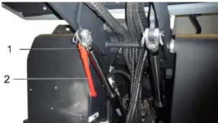
1 Holder of safety rod 2 Safety rod. Fold the safety rod for the high emptying up and insert it into the holder (secured).
Safety notes regarding the batteries. Please observe the following warning notes when handling batteries:
| Observe the directions on the battery, in the instructions for use and in the vehicle operat-ing instructions! |
| Wear an eye shield! |
| Keep away children from acid and batteries! |
| Risk of explosion! |
| Fire, sparks, open light, and smoking not allowed! |
| Danger of causticization! |
| First aid! |
| Warning note! |
| Disposal! |
| Do not throw the battery in the dustbin! |
Danger
Risk of explosion! Do not put tools or similar on the battery, i.e. on the terminal poles and cell connectors.
Danger
Risk of injury! Ensure that wounds never come into contact with lead. Always clean your hands after having worked with batteries.
DANGER
Risk of fire and explosion!
Smoking and naked flames are strictly prohibited. Rooms where batteries are charged must have good ventilation because highly explosive gas is emitted during charging.
Danger
Danger of causticization!
Rinse thoroughly with lots of clear water if acid gets into the eye or comes in contact with the skin. - Then consult a doctor immediately. - Wash off the acid if it comes in contact with the clothes.
Installing and connecting the battery
Insert battery in battery mount. Screw on mounts on battery base. Connect pole terminal (red cable) to positive pole (+). Connect pole terminal to negative pole (-).
Note: Check that the battery pole and pole terminals are adequately protected with pole grease.
Check fluid level in the battery and adjust if required
CAUTION
Regularly check the fluid level in acid-filled batteries.
The acid in a fully charged battery has a specific weight of 1.28 kg/l at a temperature of 20°C. The acid in a partially discharged battery has a specific weight between 1.00 and 1.28 kg/l. The specific weight of the acid must be uniform in all cells. Unscrew all cell caps. Take a sample from each cell using the acid tester. Put the acid sample back into the same cell. Where fluid level is too low, top up cells to the mark provided with distilled water. Charge battery. Screw in cell caps.
Charging battery
riangle Danger
Risk of injury! Comply with safety regulations on the handling of batteries. Observe the directions provided by the manufacturer of the charger.
riangle Danger
Charge the battery only with an appropriate charger.
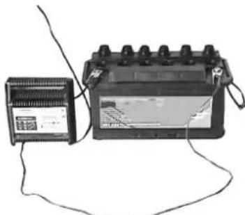
Unscrew all cell caps. Connect positive terminal cable from the charger to the positive pole connection on the battery. Connect negative terminal cable from the charger to the negative pole connection on the battery. Plug in mains connector and switch on charger. ightarrow Charge battery using lowest possible level of charging current.
Note: When the battery is charged, first remove the charger from the mains and then disconnect it from the battery.
Remove the battery
ightarrow Disconnect pole terminal to negative pole (-). ightarrow Disconnect pole terminal to positive pole (+) ightarrow Loosen the mounts on battery base. ightarrow Remove the battery from the battery holder. ightarrow Dispose of the used battery according to the local provisions.
Check engine oil level and top up, if required
riangle Danger
Risk of burns!
ightarrow Allow engine to cool down. Wait for at least 5 minutes after switching off the engine before checking the engine oil fill level.
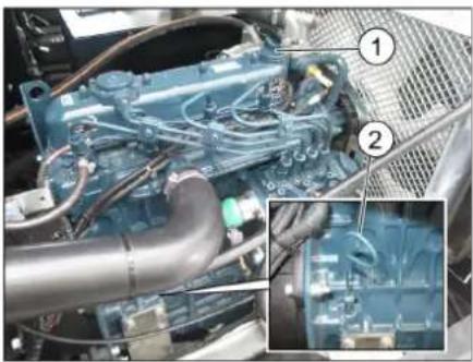
1 Screw cap, oil fill opening 2 Oil dipstick Pull out oil dipstick. Wipe off oil dipstick and insert. Pull out oil dipstick. Read the value of the oil level. Insert the oil dip again.
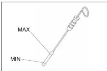
- The oil level must lie between "MIN" and "MAX" marking.
- Add motor oil if the oil level is below the "MIN" marking.
- Do not fill oil above the "MAX" marking. Loosen the screw cap of the oil filling opening. Fill in motor oil. Oil grade: see Technical Data. Close oil filler opening. Wait at least 5 minutes. Check engine oil level.
Change the motor oil and the oil filter. WARNING
Risk of burns!
To change the motor oil and motor oil filter, allow the vehicle to cool down until there is no longer a risk of burns.
Note
A warm motor facilitates the draining of the motor oil.
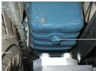
1 Oil drain screw
Prepare a collection container for at least 10 litres of oil. Switch off engine. Remove oil cap. Unscrew oil drain plug. Drain off oil.
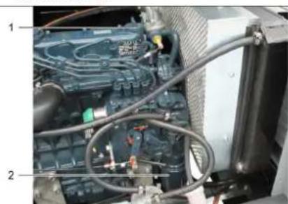
1 Oil filler cap
2 Engine oil filter
Unscrew the oil filter. Clean the intake and sealing areas. Coat the washer of the new oil filter with oil before fitting it. Fit in the new oil filter and tighten it by hand. Screw in the oil drain plug with the new seal.
Tightening torque: Nm
Fill in motor oil. For oil type and filling quantity refer to Chapter "Technical specifications". Close oil cap. Let the motor run for approx. 30 seconds. Wait at least 5 minutes. Check engine oil level. Check for leaks. Deliver the old oil to the respective collection centres.
Cleaning and replacing the air filter
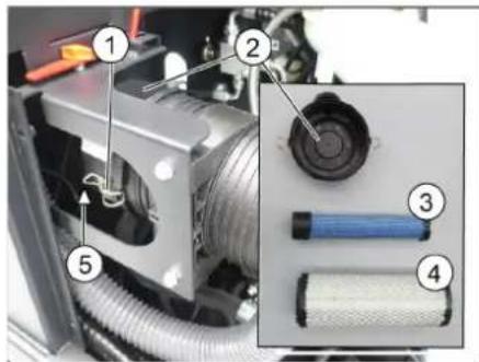
1 Locking
2 Air filter housing 3 Safety cartridge 4 Filter cartridge 5 Blowout opening pointing downwards
Open the lock. Remove the air filter housing. Remove the filter cartridge. Clean the interior of the air filter reservoir. Only remove the safety cartridge if it is being replaced. Clean the filter insert: Tap out the dust on a hard surface, blow out from inside to outside with compressed air at max. 30 psi (2 bar). The seal face and filter insert must be clean and free of damage upon installation. Insert the cleaned filter insert. Important: A severely contaminated or damaged filter insert must be replaced. If the filter insert is being replaced, replace the safety cartridge too. Important: No dust is allowed to enter through the suction opening when replacing the filter insert and safety cartridge
Note: Installation position with blowout opening pointing down (see illustration).
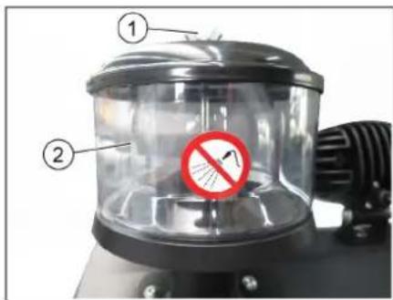
1 Wing nut 2 Centrifugal separator Unscrew the wing nut from the centrifugal separator. Clean the centrifugal separator.
Check hydraulic oil level and refill hydraulic oil
NOTICE
The waste container must not be raised.
Open engine cover.
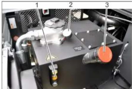
1 Hydraulic oil sight glass 2 Manometer 3 Screw cap, oil fill opening Check hydraulic oil level in the looking glass. The oil level must lie between "MIN" and "MAX" marking. - Add hydraulic oil if the oil level is below the "MIN" marking. Loosen the closing cap of the oil filling opening. Clean the filling area. Refill hydraulic oil.
Oil grade: see Technical Data
Replace and tighten the closing cap of the oil filling opening.
NOTICE
If the pressure gauge shows an increased hydraulic oil pressure, the hydraulic oil filter must be replaced by Karcher customer service.
Check hydraulic unit
NOTICE
Only Kärcher Customer Service is authorised to carry out maintenance tasks on the hydraulic unit.
Lock parking brake. Start the motor. Check all hydraulic hoses and connections and ensure that they are leak-proof.
Check water cooler and maintain it. Danger
Danger of scalding by boiling water! Let the cooler cool down for at least 20 minutes.
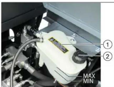
1 Coolant expansion tank 2 Closing head. Check the cooling water level on the balance reservoir (water level between MIN and MAX). Clean cooler lamella. Check cooler hoses and connections and ensure that they are leak-proof.
Checking roller brush
Start the motor. Raise the waste container up to the end-position. Switch off engine. Lock parking brake. Use the safety bar for emptying from a height. Remove belts or cords from roller brush. Remove the safety bar. Start the motor. Lower the waste container up to the end-position. Switch off engine.
Replacing roller brush
With the waste container lowered.
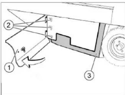
1 Side panel, right
2 Wing nut
3 Side seal
Open right side panel with key. Unscrew the wingnuts from the holding plate side seals and remove the holding plate.
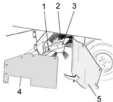
1 Fastening screws of the roller brush intake
2 Roller brush 3 Roller brush intake 4 Holding plate for side seal 5 Side seal. Flip the side seal out. Unscrew the retaining screw of the roller brush intake, and swing the intake to the outside. Pull out roller brush.
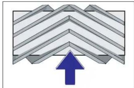
Installation position of roller brush in direction of travel (top view)
Note: When installing the new roller brush, ensure correct positioning of the bristle assembly.
Install new roller brush. The nuts of the roller brush must be inserted on the notches of the opposite crank.
Note: Once the new roller brush has been installed, the sweeping track must be readjusted.
Check and adjust roller brush sweeping track
Check tyre pressure. Switch off suction blower. Drive sweeper on to a smooth, even surface covered with a visible layer of dust or chalk. Lower the roller brush by means of the control lever and let it run (approx. 10 s). Raise roller brush. Drive machine backwards. Check sweeping mirror.
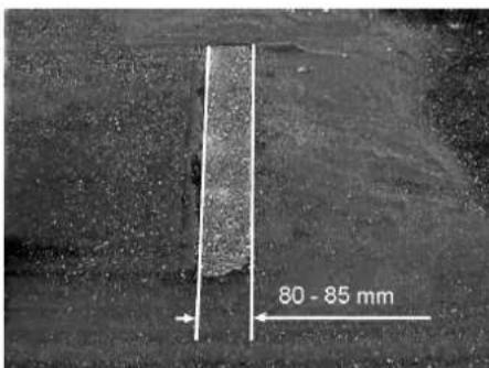
The sweeping track should have an even rectangular shape which is 80 - 85 mm wide. Adjusting the sweeping level
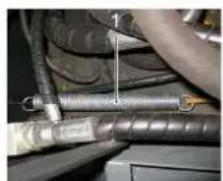
1 Spring
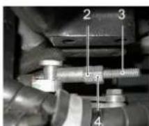
2 Rating nut 3 Lock nut 4 Threaded rod Adjust the sweeping track position by adjusting the adjustment screw. Check sweeping mirror.
Check and adjust sweeping track of the side-brush
Check tyre pressure. Raise the roller brush and side brushes using the control levers. Drive sweeper on to a smooth, even surface covered with a visible layer of dust or chalk. Control lever side brush (3) to the front: Side brush is lowered. Allow the side brushes to run for approx. 10 seconds. The side-brushes lift up. Drive machine backwards. Check sweeping mirror.
The width of the sweeping track should lie between 40-50 mm.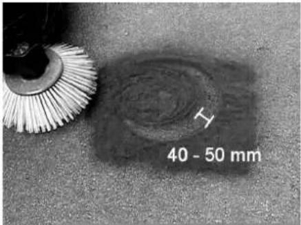
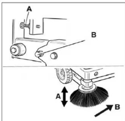
Set the sweeping track using the two adjusting screws. Check sweeping mirror.
Adjust the side seals
Check tyre pressure. Drive the waste container up and secure it with the safety rod.
DANGER
Risk of injury! Always apply the safety bar when the waste container is raised. Fold the safety rod for high emptying up and insert it into the holder (secured).
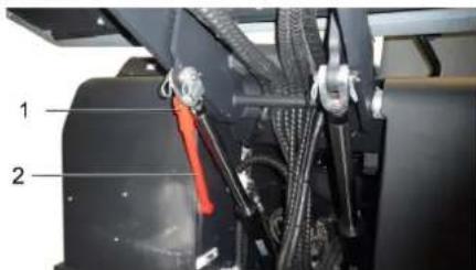
1 Holder of safety rod
2 Safety rod
Open the side cover as described in Chapter "Replace brush roller". Release the 6 wing nuts on the side holding plate. Loosen 3 nuts (SW 13) on the front holding plate. Press the side seal down (elongated hole) until it is about 1 to 3 mm from the floor. Screw in the holding plates. Repeat the procedure on the other side of the appliance.
Check the tyre pressure
Park the sweeper on an even surface. Connect air pressure testing device to tyre valve. Check air pressure and adjust if required. For permissible tyre air pressures see "Technical data".
Checking/changing the fine dust filter WARNING
Risk of injury!
Wear a dust mask when working around the dust filter. Observe safety regulations on the handling of fine particles.
Clean the fine dust filter with the filter cleaning button. Empty waste container.
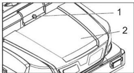
1 Lock of appliance hood
2 Cover. Open the lock, remove the star grip screw to do this. Fold cover forwards.
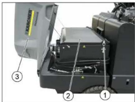
1 Lock, filter cover (2x) 2 Filter cover 3 Cover. Open filter cap.
1 Fine dust filter 2 Filter cover 3 Cross struts. Open filter cap. Check the fine dust filter, clean or replace if necessary.
Note
Exchanging the fine dust filter may only be done by Karcher Customer Service. Insert and lock the filter cover.
Check and adjust the V-Belt
The V-Belt must deflect approx. 7-9 mm at a pressure of 10 kg.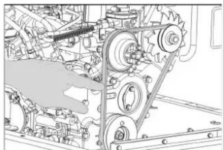
Get the V-belt tension adjusted by an authorized customer service.
Replacing fuses
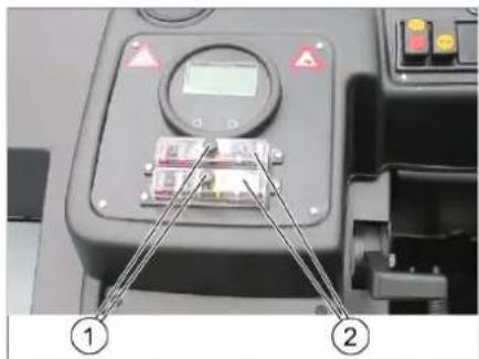
1 Lock nut
2 Cover fuse box
Unscrew the knurled nut. Open the cover on the fuse box. Check the fuses. Replace defective fuses.
Note: Only use fuses with identical safety ratings.
Check the fuses.
| FU 01 Ignition 10 A |
| FU 02 Pre-heat 5 A |
| FU 03 Multifunction display 5 A |
| FU 04 Vibrator system 20 A |
| FU 05 Reverse warning system and flap indicator |
| FU 06 Cabin lighting Windshield wiper (option) |
| FU 07 Lights Blinker (option) |
| FU 08 Lights Blue Spot (option) |
| FU 09 Rear position lights (op-tion) |
| FU 10 Dipped beam (option) 10 A |
| FU 11 Front position lights (op-tion) |
| FU 12 Hydraulic cooler 25 A |
| FU 13 Main fuse 60 A |
| FU 15 Spark plugs 70 A |
| FU 20 Fan (option) 20 A |
| FU 21 Fan cabin (option) 25 A |
| FU 22 Compressor (option) 7,5 A |
Replace defective fuses.
Note: Only use fuses with identical safety ratings.
EU Declaration of Conformity
We hereby declare that the machine described below complies with the relevant basic safety and health requirements of the EU Directives, both in its basic design and construction as well as in the version put into circulation by us. This declaration shall cease to be valid if the machine is modified without our prior approval.
Product: Ride-on vacuum sweeper
Type: 1.186-145.0
Relevant EU Directives
2006/42/EC (+2009/127/EC)
2014/30/EU
2000/14/EC
Applied harmonized standards
EN 60335-1
EN 60335-2-72
EN 55012: 2007 + A1: 2009
EN 61000-6-2: 2005
EN 62233: 2008
Applied national standards
Applied conformity evaluation method
2000/14/EC: Appendix V
Sound power level dB(A)
Measured: 100
Guaranteed: 103
The signatories act on behalf of and with the authority of the company management.
Chairman of the Board of Management

S. Reiser
Director Regulatory Affairs & Certification
Documentation supervisor:
S. Reiser
Alfred Kärcher SE & Co. KG
71364 Winnenden (Germany)
Tel.: +49 7195 14-0
Fax: +49 7195 14-2212
Winnenden, 2022/02/01
Declaration of Conformity
We hereby declare that the product described below complies with the relevant provisions of the following UK Regulations, both in its basic design and construction as well as in the version put into circulation by us. This declaration shall cease to be valid if the product is modified without our prior approval.
Product: Ride-on vacuum sweeper
Type: 1.186-145.0
Currently applicable UK Regulations
S.I. 2008/1597 (as amended)
S.I. 2016/1091 (as amended)
S.I. 2001/1701 (as amended)
Designated standards used
EN 60335-1
EN 60335-2-72
EN 55012: 2007 + A1: 2009
EN 61000-6-2: 2005
EN 62233: 2008
Applied national standards
Applied conformity assessment procedure
S.I. 2001/1701 (as amended): Schedule 8
Sound power level dB(A)
Measured: 100
Guaranteed: 103
The signatories act on behalf of and with the authority of the company management.
H. Jenner
Chairman of the Board of Management
S. Reiser
Director Regulatory Affairs & Certification
Documentation supervisor:
S. Reiser
Alfred Kärcher SE & Co. KG
71364 Winnenden (Germany)
Tel.: +49 7195 14-0
Fax: +49 7195 14-2212
Winnenden, 2022/02/01
| Troubleshooting | |
| Fault Remedy | |
| Appliance cannot be started | Sit on the driver seat, the seat contact switch gets activated. |
| Charging or replacing battery | |
| Fill in fuel,deaerate the fuel system | |
| Change fuel filterReplace fuel prefilter | |
| Check fuel pipes,connections and joints and maintain them if required | |
| Inform Kärcher Customer Service. | |
| Engine is running erratically | Clean air filter or change filter cartridge. |
| Check fuel pipes,connections and joints and maintain them if required | |
| Inform Kärcher Customer Service. | |
| Engine is overheated Refill coolant | |
| Rinse cooler | |
| Tighten V-Belt | |
| Inform Kärcher Customer Service. | |
| Engine is running but machine is only moving slowly or is not moving at all | Release parking brake |
| Check for trapped ribbons and strings. | |
| Inform Kärcher Customer Service. | |
| Whistling sound in the hydraulic system | Refill hydraulic fluid |
| Inform Kärcher Customer Service. | |
| Brushes are rotating slowly or not at all | Move the gas lever all the way to the front (high speed). |
| Check for trapped ribbons and strings. | |
| Inform Kärcher Customer Service. | |
| Too little or no suction power in the brush area | Clean filter |
| Inform Kärcher Customer Service. | |
| Dust gathers in the machine Adjust | the side seals |
| Switch on blower | |
| Clean dust filter | |
| Replace filter washers | |
| Inform Kärcher Customer Service. | |
| Sweeping unit does not pick up waste | Empty waste container |
| Close the waste container completely. | |
| Clean dust filter | |
| Replacing roller brush | |
| Adjust sweeping track | |
| Replace sealing strips of the waste container | |
| Remove the blocking of the brush roller | |
| Inform Kärcher Customer Service. | |
| Waste container does not raise or lower | Remove the locking support from the waste container |
| Inform Kärcher Customer Service. | |
| Waste container is rotating slowly or not at all | Inform Kärcher Customer Service. |
| Operation problems with hydraulic movement parts | Inform Kärcher Customer Service. |
Technical specifications
| KM 170/600 R D Classic | ||
| Machine data | ||
| Drive speed, forward km/h 14 | ||
| Drive speed, reverse km/h 14 | ||
| Climbing capability (max.) -- 18% | ||
| Surface cleaning performance without side brushes m | 2/h 18800 | |
| Surface cleaning performance with 1 side brushes m | 2/h 23800 | |
| Surface cleaning performance with 2 side brushes m | 2/h 28000 | |
| Working width without side brushes mm 1344 | ||
| Working width with 1 side brushes mm 1700 | ||
| Working width with 2 side brushes mm 2000 | ||
| Protection type, drip-proof -- IPX 3 | ||
| Usage duration when tank is full h 4,5 | ||
| Engine | ||
| Type | -- Kubota | V1505 (E4B) |
| Type | -- 4-cylinder 4-stroke diesel engine | |
| CO2Emission according to the measurement procedure of EU regulation 2016/1628 (level V) | g/kWh | 1018,0 |
| Cooling type | -- Water cooling | |
| Rotation direction | -- Anticlockwise direction | |
| Cylinder capacity | cm³ | 1498 |
| Max. power | kW/PS | 18,5/24,82300 1/min |
| Battery | V, Ah | 12, 72 |
| Fuel | ||
| Engine oil volume | I | 6 |
| Engine oil type | >25 °C | SAE30, SAE10W-30, SAE15W-40 |
| 0 - 25 °C | SAE20, SAE10W-30 | |
| < 0 °C | SAE10, SAE10W-30 | |
| Hydraulic oil | -- Renol HV 46 | |
| Hydraulic oil volume | I | 37 |
| Coolant (SAE J814C) | -- Stilmoil Antifrost | |
| For points to be lubricated manually | Multi-purpose grease | |
| Waste container | ||
| Max. unloading height | mm 1540 | |
| Volume of waste container | I | 600 |
| Roller brush | ||
| Roller brush diameter | mm 400 | |
| Roller brush width | mm 1344 | |
| Speed | 1/min | 340 |
| Sweeping track | mm 80 | |
| Side brushes | ||
| Side brush diameter | mm 650 | |
| Speed (continuous) | 1/min | 0 - 63 |
| Tyres | ||
| Size, front | -- 6.00-8 | |
| Air pressure, front | bar | 8 |
| Size, rear | -- 5.00-8 | |
| Air pressure, rear | bar | 8 |
| Brake | ||
| Front wheels | -- mechanical | |
| Rear wheel | -- hydrostatic | |
| Filter and vacuum system | ||
| Type -- Flat fold filter | ||
| Speed 1/min 2900 | ||
| Filter surface area, fine dust filter m | 2 | 9,1 |
| Nominal vacuum, suction system mbar 18,5 | ||
| Nominal volume flow, suction system m | 3/h 1650 | |
| Vibrator system -- Electric motor | ||
| Working conditions | ||
| Temperature °C -5 and +40 | ||
| Air humidity, non-condensing % 0 - 90 | ||
| Values determined as per EN 60335-2-72 | ||
| Noise emission | ||
| Sound pressure level LpA | dB(A) 82 | |
| Uncertainty KpA | dB(A) 3 | |
| Sound power level LwA + Uncertainty KwA | dB(A) 103 | |
| Machine vibrations | ||
| Hand-arm vibration value | m/s2 | 0,7 |
| Uncertainty K | m/s2 | 0,2 |
| Seat | m/s2 | 0,5 |
| Uncertainty K | m/s2 | 0,1 |
| Dimensions and weights | ||
| Length x width x height | mm | 2742 x 1904 x 2213 |
| Right turning radius | mm | 2525 |
| Left turning radius | mm | 2490 |
| Unladen weight (without attachment sets) | kg | 1695 |
| Permissible overall weight | kg | 2701 |
| Permissible front axle load | kg | 1703 |
| Permissible rear axle load | kg | 998 |
| Capacity of fuel tank, diesel | l | 26 |
| Subject to technical modifications! | ||

2 Pedal "forward" 3 Pedal "reverse"
2006/42/EC (+2009/127/EC)
2014/30/EU
2000/14/EC
71364 Winnenden (Germany)
Tel.: +49 7195 14-0
Fax: +49 7195 14-2212
Winnenden, 2022/02/01
2006/42/EC (+2009/127/EC)
2014/30/EU
2000/14/EC
Chairman of the Board of Management
S. Reiser
Director Regulatory Affairs & Certification
71364 Winnenden (Germany)
Tel.: +49 7195 14-0
Fax: +49 7195 14-2212
Winnenden, 2022/02/01
www.kaercher.com/REACH
Warranty
71364 Winnenden (Germany)
Tel.: +49 7195 14-0
Fax: +49 7195 14-2212
Winnenden, 2022/02/01
www.kaercher.com/REACH
Warranty
2006/42/EC (+2009/127/EC)
2014/30/EU
2000/14/EC
71364 Winnenden (Germany)
Tel.: +49 7195 14-0
Fax: +49 7195 14-2212
Winnenden, 2022/02/01
Adjust the driver's seat
2006/42/EC (+2009/127/EC)
2014/30/EU
2000/14/EC
71364 Winnenden (Germany)
Tel.: +49 7195 14-0
Fax: +49 7195 14-2212
Winnenden, 2022/02/01
www.kaercher.com/REACH
Warranty
Chassis over bindings
NOTE
2006/42/EC (+2009/127/EC)
2014/30/EU
2000/14/EC
H. Jenner Chairman of the Board of Management

S. Reiser Director Regulatory Affairs & Certification
71364 Winnenden (Germany)
Tel.: +49 7195 14-0
Fax: +49 7195 14-2212
Winnenden, 2022/02/01
Lashing point
Tire pressure (max)
Jacking point
Advice for unloading
△Danger
Danger of personal injury, danger of material damage!
www.kaercher.com/REACH
Warranty
Danger of burns!
Danger of burns!
Set the sweeping brush
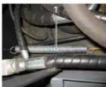
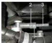
1Spring
2Adjusting nut
3Lock nut
4Threaded bolt
2006/42/EC (+2009/127/EC)
2014/30/EU
2000/14/EC
Applicable standards
EN 60335-1
EN 60335-2-72
EN 55012: 2007 + A1: 2009
EN 61000-6-2: 2005
EN 62233: 2008
S. Reiser Director Regulatory Affairs & Certification
71364 Winnenden (Germany)
Tel.: +49 7195 14-0
Fax: +49 7195 14-2212
Winnenden, 2022/02/01
www.kaercher.com/REACH
Warranty
71364 Winnenden (Germany)
Tel.: +49 7195 14-0
Fax: +49 7195 14-2212
Winnenden, 2022/02/01
www.kaercher.com/REACH
Warranty
2 Drive forward 3 Drive backward
H.Jenner Chairman of the Board of Management

S. Reiser
Director Regulatory Affairs & Certification
71364 Winnenden (Germany)
Tel.: +49 7195 14-0
Fax: +49 7195 14-2212
Winnenden, 2022/02/01
Danger of tipping over when the device is used on slopes. - Operate the machine only on stable ground. Risk of tipping over when the slope is too steep. The maximum permissible incline is 10%. - Due to the risk of fire and explosion, the machine must not be used in rooms above 2000 m. - (Applies only to battery-operated devices) If the machine is equipped with PVC hoses, it may only be used at low ambient temperatures (below 0°C). For questions regarding your machine, contact Kärcher. - Always observe the safety regulations and accident prevention regulations applicable to the device. - The operator of the device must be familiar with the regulations and instructions. The operator must comply with local conditions and pay attention to other persons, especially children, during work. - The device may only be used by persons who have been instructed in its use or have demonstrated their competence and have been authorized to use it. - The device must not be used by children. - It is forbidden to climb onto the machine. - Combustion engines may only be operated at the place of use. → To prevent unauthorized use, do not leave the key on the machine. → The device must never be left unattended while the engine is running. The operator may only leave the machine after stopping the engine, securing the machine against unintentional movement, engaging the parking brake if necessary, and removing the key.
www.kaercher.com/REACH
The device is switched off. -> The lever for the locking device (4) is pressed: The locking device opens. The suction foot is raised. The device is switched on. -> For cleaning surfaces: The lever for the suction foot (1) is pressed forward: The suction foot is switched off and lowered. During vertical side lifting, the lever for the side lifting (3) is pressed outward: The side lifting is lowered.
Chairman of the Board of Management
S. Reiser
Director Regulatory Affairs & Certification
Responsible for documentation: S. Reiser
Alfred Karcher SE & Co. KG
71364 Winnenden (Germany)
Tel.: +49 7195 14-0
Fax: +49 7195 14-2212
Winnenden, 2022/02/01
www.kaercher.com/REACH
Guaranteed
Before starting work, every day
Chairman of the Board of Management
Director Regulatory Affairs & Certification
71364 Winnenden (Germany)
Tel.: +49 7195 14-0
Fax: +49 7195 14-2212
Winnenden, 2022/02/01
For malfunctions, assistance
To brake/release
Parking brake...RU5
Exceeding the limit
Without own
Drive. .RU 5
Exceeding the limit
Using the device
with its own drive. RU5
Start of operation. RU5
General information. RU5
Maintenance work. RU5
Technical maintenance. RU5
Operation. RU5
Adjust the position. RU5
Day of the driver. RU5
Starting the device. RU5
Switching to the device
RU6
Refueling. RU6
Empty the reservoir
Dispose of waste. RU7
Device connection..RU7
Transportation RU7
Storage/Removal from operation
U7
Maintenance and technical service
Bath. RU 7
General instructions RU7
U7
Frequency of technical
maintenance RU7
Maintenance work
1R8
Declaration of conformity EURU 13
Troubleshooting assistance. RU 14
Technical data .RU 15
Specified equipment
Safety

Danger of hearing damage. Wear hearing protection.
Symbols in the operating
instructions
DANGER
Indicates an imminent danger that will result in serious or fatal injury.
WARNING
Indicates a potentially dangerous situation that could result in serious or fatal injury.
CAUTION
Indicates a potentially dangerous situation that could result in minor or moderate injury or property damage.
Symbols on the device

Danger of burns from hot surfaces! Before working on the device, the system must cool down.

Work on the device should always be carried out only in accordance with the safety instructions.

Danger of entanglement with rotating parts of the machine.

Danger of injury. Do not touch.

Danger of injury. Do not allow entry of foreign or loose objects.
Protective cap for the network / location of the valve. Stable place for fastening.
Air pressure in the cover (max.)
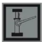
Lifting points for opening

Maximum surface inclination when moving with a raised bunker.
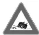
In the direction of movement, driving on slopes up to 18% is permitted.
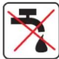
Danger of injury! Do not operate the device with a thin layer.
General instructions
If damage is found during unpacking of the device, damage caused during transport, you should immediately contact the trade organization that sold you this product.
- Warning and information plates attached to the device contain important information necessary for safe operation of the device.
- In addition to the safety instructions contained in the operating manual, it is also necessary to comply with the general provisions of the legislation on safety and prevention of accidents.
Instructions for unloading
Danger! Danger of damage!
When loading, pay attention to the weight of the device.
Weight in the delivery condition (without accessories) 1695 kg
*With the installation kit installed, the weight of the device becomes correspondingly even more significant.
Do not use hooks for loading. → When loading the device, use suitable lifting equipment. → When using lifting equipment, it is necessary to pay attention to the following: Roads with a slope of up to 7°. → If the device is delivered on a pallet, it is necessary to build a ramp from the supplied accessories for unloading. Instructions can be found on page 2 (on the inside of the cover).
Important note: Each cover must be secured with 2 screws.
Operating mode for the internal combustion engine
Danger
Danger
Danger to health, danger of damage! Danger of injury! Danger of tipping over on too steep slopes. In the direction of travel, slopes up to 18% are permissible. Danger of tipping over when driving fast around corners. When cornering, the speed must be reduced. Danger of tipping over on unstable ground. The device may only be moved on solid ground. Danger of tipping over with a large lateral inclination. In directions perpendicular to the direction of travel, the device may only be moved on slopes up to max. 10%. -To maintain the air parameters, the device is approved for operation at altitudes up to 2000 meters above sea level. -(Only for certain models)If the device is equipped with a PBX hose, it is prohibited to use it at low ambient temperatures (below 0°C). If questions arise regarding the device, contact the company Karcher. -Also, all regulations, rules, and standards regarding transport vehicles must be observed. -Operating personnel must use the device in accordance with its intended purpose. During operation, they must take into account local conditions and, when working with the device, watch out for other people, especially children. -Working with the device is permitted only for persons who have been instructed in the operating instructions and have confirmed their qualification for maintenance. -Operation of the device by persons with limited physical, sensory, or mental capabilities is prohibited. -It is not permitted to take passengers along. -The device must be operated by trained personnel only. To prevent unauthorized use of the device, the ignition key must be removed. It is forbidden to leave the device with the engine running. Operating personnel may only leave the device after the engine has been stopped, the device has been secured against accidental movement, and if necessary, the device has been placed on the parking brake, and the ignition key has been removed.
Page
Danger
Danger of injury!
Before starting the engine, do not lean over and do not touch it (danger of burns). Do not lean over or touch the drive belt (danger of burns). The exhaust gases are toxic and harmful to health, it is forbidden to inhale them. After switching on the engine, wait 3-4 seconds for inertia. During this time, stay away from the drive zone.
Devices with driver's cab
In case of emergency, break the glass with a hammer in case of an accident.
NOTICE
The hammer is located in the area of the driver's seat, under the seat.
Spare parts liability
Only use genuine spare parts and accessories approved by the manufacturer. Using non-genuine accessories or spare parts does not guarantee reliable operation of the device. Further information on spare parts can be found on our website www.kaercher.com in the Service section.
Environmental protection

Packaging materials are recyclable. Please do not dispose of packaging with household waste, but take it to one of the collection points for recyclable materials.
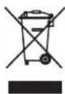
Old devices contain recyclable materials that should be sent for recycling. Batteries, oils and similar materials must not enter the environment. Therefore, dispose of old devices through appropriate waste collection systems.
Instructions for handling components (REACH)
Current information on components can be found on the website at the following address:
www.kaercher.com/REACH
Warranty
In each country, the warranty conditions published by the authorized distributor apply. Possible malfunctions of the device during the warranty period are repaired free of charge if they are due to material defects or manufacturing errors. In case of complaints during the warranty period, please contact the dealer who sold you the device or the nearest authorized customer service.
Data is displayed on the factory plate in coded form.
The symbols have the following meaning:
Example: 30190
3 year of manufacture 0 decade of manufacture 1 year of decade 9 second digit of month of manufacture 0 first digit of month of manufacture
Thus, in this example, code 30190 indicates the date of manufacture 09/(2)013.
Purpose
Purpose of the device.
-The sweeping brush sweeps debris directly into the refuse container. -The side brush guides debris onto the main brush surface and delivers it into the working area of the sweeping roller. -Dust bag: dust is sucked in by the suction fan through the filter.
Intended use
Use this sweeping machine exclusively in accordance with the instructions and this operating manual.
→ Before starting work, the device and its accessories must be checked for their proper condition and compliance with safety requirements. If the device is not in perfect condition, it must not be used. -This sweeping machine is intended for sweeping contaminated surfaces in the open air. -Operation of the device in enclosed spaces is prohibited. -Devices without the necessary safety equipment (installed at the factory) are not permitted to be used on public roads. -The device may be used on public roads only after prior individual approval by the responsible authority. -All covers of the device may only be opened in areas protected from water. -The device is not intended for collecting substances hazardous to health. -Unauthorized modifications to the device are prohibited. - Never use the device for sweeping/suction of explosive liquids, flammable gases, or concentrated acids and solvents! -Do not allow the device to sweep/suck up burning or glowing objects. -The device is intended only for sweeping the surfaces specified in this operating manual. -The device may only be used on surfaces approved by the manufacturer or its representative for use with sweeping machines. -It is forbidden to be in the danger zone. Operation of the device in explosive areas is prohibited. -As a general rule, the following applies: Do not allow the device to come into contact with easily flammable substances (risk of explosion/fire).
Surfaces to be swept
DANGER
Danger of injury from reduced load-bearing capacity of the ground before driving.
Asphalt
- Thought-out zeros
Daily work schedule
→ Check the fuel tank filling. Check the engine oil level. Check the coolant level. Check the pressure in the tires. Check the V-belt for wear and the presence of wound elements. → Check the wheels for the presence of wound elements. → Check the centrifugal separator and air filter, if necessary, clean them. → Check the proper condition of all control elements. → Check the device for damage. → Perform cleaning of the dust filter using the filter cleaning cone.
Note: See description in the chapter "Maintenance and technical service".
Protection against freezing
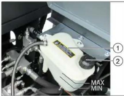
1 Compensation tank of the radiator with liquid cooling
2 Locking cap
→ In case of danger of freezing, check whether the antifreeze contains coolant.
Refueling
Danger
Explosion hazard!
Only use the fuel specified in the operating manual. Refueling in closed rooms is not allowed. Smoking and open fire are prohibited. Make sure that fuel does not get on hot surfaces. Turn off the engine. Close the shut-off device of the tank. Fill with diesel fuel. At outside temperatures below 6 °C, only use winter diesel fuel, otherwise, due to the coagulation of fuel components, problems may arise during operation. → Drain the fuel and close the tank cap. Close the tank valve.
Operation
Adjust the position of the driver's seat
→ Pull the lever to adjust the seat. → Move the seat, release the lever and let it lock. → Check its fixation by moving the seat back and forth.
Starting the device
ATTENTION
→ Move the machine on level ground. All four control levers must be in neutral position. During start-up, do not press the accelerator pedal! The device is equipped with a safety switch. When the safety switch is activated, the device switches off. → The fine dust filter automatically cleans itself when the engine is switched off.
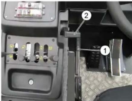
1 Parking brake 2 Engine speed control lever Diesel engine: Start the engine. Press the parking brake. → Set the engine speed to approx. 75% of maximum speed. Insert the key into the ignition switch. → Turn the key to the ignition ON position (position I). Diesel engine: The control indicator lights up. As soon as the control indicator goes out, turn and hold the key in the start position until the engine starts (max. 10 seconds). Release the key. The key returns to position I. → At ambient temperatures below 0°C: Before starting work, warm up the engine at low speed.
Note
If the engine does not start, repeat the starting procedure.
Checks on the device
DANGER
Danger of accidents from moving parts!
→ Moving with the mower deck raised is prohibited!
CAUTION
Danger of injury!
→ Before moving or driving the machine, ensure that the mower deck is sufficiently raised. → Always press the accelerator pedal carefully and slowly. It is not permitted to abruptly change the direction of travel from forward to reverse and vice versa.
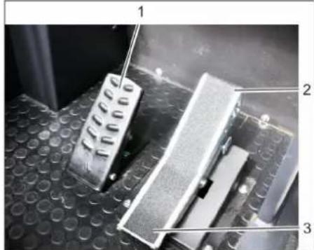
1 Brake pedal 2 Forward drive pedal 3 Reverse drive pedal
→ Smoothly push the engine speed control lever forward (working speed). Press and hold the brake pedal. Release the parking brake. → Smoothly press the accelerator pedal. → Control the direction of travel with the steering wheel.
Note: Use of aggressive cleaning agents is not permitted.
Maintenance frequency
Note: The hour meter must be used to determine when maintenance is due.
Maintenance performed by the customer
Note: All maintenance work on the customer side must be carried out by qualified specialists. If necessary, you can contact a specialized trade organization of the Karcher company at any time.
Daily maintenance:
Check the fuel tank fill level. Check the oil level in the engine. Check the coolant water level. Check the tire pressure. Check the side brushes for wear and for tangled debris. Check the wheels for tangled debris. Check the separator and air filter, clean if necessary. Check the condition of all control elements. Check the device for damage. Clean the dust filter with the filter cleaning lever.
Weekly maintenance:
Check the fuel filter. Clean the water radiator. Clean the hydraulic oil cooler. Check the hydraulic system. Check the oil level in the hydraulic system. Check the brake fluid level. Check the wear of the wear pads, replace if necessary. Check and lubricate the reservoir cover.
Maintenance of wearing parts:
Replace the sealing strips. Adjust or replace the side seals. Replace the squeegee. Replace the side brushes.
Note: See the chapter "Maintenance work" for a description.
Maintenance performed by the service department
Maintenance after 50 hours of operation:
Perform the first maintenance service in accordance with the service inspection form.
Maintenance after 250/500/1000/1500/2000 operating hours:
Perform maintenance in accordance with the service inspection form.
Note: To retain the right to warranty service, all work on technical and preventive maintenance during the warranty period must be carried out by the authorized Karcher service department in accordance with the maintenance brochure.
Maintenance work
Preparation:
→ Place the sweeping machine on a level surface. → Turn the ignition key to position "0" and remove it from the lock. Engage the parking brake.
General safety information
DANGER
Danger of injury! Always install protective grilles when the debris container is raised.
1Hold the protective grille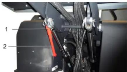
2Fold the protective grille upwards, hook the protective grille into the detent of the raised container and insert it into the holder (protective grille).

Please do not allow motor oil, fuel, diesel fuel, or gasoline to enter the environment. Please protect the soil and dispose of used oil properly, do not cause damage to the environment.
Safety information on handling batteries
When handling batteries, the following precautionary instructions must be observed:
Checking and correcting the electrolyte level in the battery
CAUTION
In batteries where acid is added, the liquid level should be checked regularly.
- The density of the electrolyte of a fully charged battery is 1.28 kg/l at a temperature of 20°C - The density of the electrolyte of a partially charged battery is from 1.00 to 1.28 kg/l. - In all cells, the density of the electrolyte must be the same. → Remove all battery cell caps. Using a hydrometer, take samples from each cell. → Pour the electrolyte samples back into the same cells. → If the liquid level is too low, fill the cells with distilled water up to the mark. Charge the battery. → Replace the battery cell caps.
Charging the battery
Danger
Danger of injury! When working with batteries, observe safety rules. Follow the operating instructions issued by the manufacturer of the charging device.
Danger
Charge the battery only with a suitable charging device.
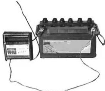
→ Remove all battery cell caps. Connect the positive cable (+) of the charging device to the positive terminal of the battery. Connect the negative cable (-) of the charging device to the negative terminal of the battery. → Plug the power cord into the mains and switch on the charging device. → The battery should be charged with a charging current of minimal current strength.
Note: After charging the battery, disconnect the charging device first from the mains, then from the battery.
Removing the battery
Disconnect the positive clamp from the negative terminal (-). Disconnect the positive clamp from the positive terminal (+). Leave the retainer on the battery base. Remove the battery from the holder. → Used batteries must be disposed of in accordance with applicable regulations.
Checking the oil level
Danger
→ Danger of burns! Check the oil level in the engine no earlier than 5 minutes after switching off the engine.
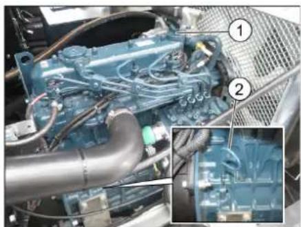
1 Cap, oil filler opening
2 Oil level indicator Pull out the oil level indicator. Wipe the indicator and insert it again. Pull out the oil level indicator. Read the oil level reading. Insert the oil dipstick again.
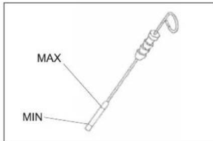
- The oil level should be between the "MIN" and "MAX" marks. - If the oil level is below the MIN mark, add oil. - Do not fill oil above the MAX mark. Open the filler cap and the oil filler opening. Fill with engine oil. Oil type: see "Technical data". Close the oil filler opening. → Wait at least 5 minutes. Check the oil level in the engine.
Replace the engine oil and oil filter
△DANGER
Danger of burns!
→ To replace the engine oil and the engine oil filter, let the machine cool down so that there is no danger of burns.
Note
The engine is hot, risk of burns from hot oil.
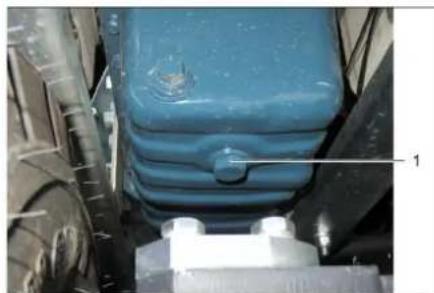
1 Threaded plug of the oil drain opening
→ Prepare an oil collection container with a capacity of at least 10 liters. Switch off the engine. Unscrew the cap of the oil filler neck. Unscrew the threaded plug. Drain the oil.
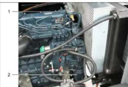
1 Cap of the oil filler opening 2 Engine oil filter Unscrew the oil filter.
Clean the locking and sealing surfaces. → Before installation, lubricate the seal of the new oil filter with oil. Insert it and screw it on by hand. Screw in the drain plug with a new seal. Tightening torque: ... Nm Fill with engine oil. The oil quantity is specified in the "Technical data" chapter. Close the cap of the oil filler neck. → Let the engine run for about 30 seconds. → Wait at least 5 minutes. Check the oil level in the engine. Check for leaks. → Dispose of the used oil at a designated collection point.
Checking and replacing the air filter
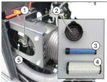
1 Plug
2 Air filter housing 3 Protective cartridge 4 Filter cartridge 5 Drain hole at the bottom. Open the cover. → Remove the air filter housing. → Remove the filter cartridge. Clean the inside of the air filter housing. The protective cartridge should only be removed if it needs to be replaced. Clean the filter element: on a hard surface, tap out the dust and blow it out with compressed air from the inside out at a pressure of max. 30 psi (2 bar). → For installation, the sealing surfaces and the filter element must be clean and undamaged. Insert the cleaned filter cartridge.
Important: A heavily soiled or damaged filter element must be replaced.
→ When replacing the filter element, also replace the protective cartridge.
Important: When replacing the filter element and the protective cartridge, dust must not get into the intake opening under any circumstances.
Note: Installation position - the intake opening points downwards (see figure).
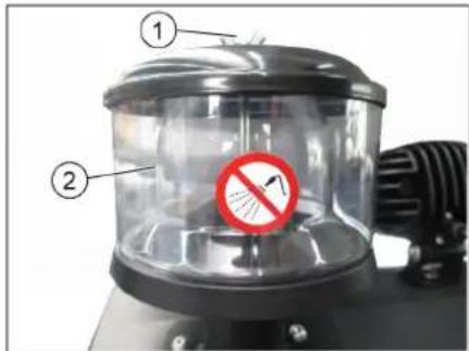
1 Drain plug 2 Centrifugal separator. Remove the drain plug on the centrifugal separator. Clean the centrifugal separator.
Check the oil level in the hydraulic system
WARNING
The waste collection container must not be overfilled.
Open the engine hood.
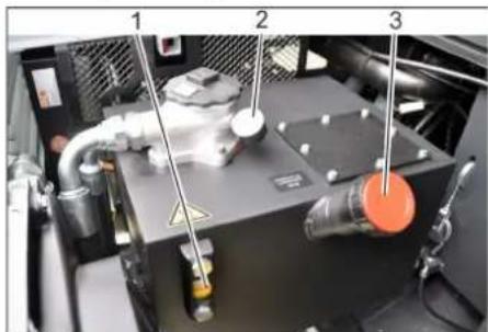
1 Sight glass for hydraulic oil 2 Pressure gauge 3 Filler cap, oil filler opening. Check the oil level in the hydraulic system in the sight glass. - The oil level must be between the "MIN" and "MAX" marks. - If the oil level is below the "MIN" mark, add oil. Unscrew the filler cap of the oil filler opening. Clean the filler area. Add oil for hydraulic systems.
Oil type: see "Technical data".
Screw the filler cap back onto the oil filler opening.
The ECD indicator points to an increase in hydraulic oil pressure; contact the Karcher service department to replace the hydraulic oil filter.
Check the hydraulic system
NOTICE
Repairs to the hydraulic system must only be carried out by trained Karcher service personnel.
Engage the parking brake. Start the engine. → Check the tightness of all hydraulic lines and connections without exception.
Checking and servicing the water radiator
Danger
Danger of scalding from boiling water! Let the radiator cool down for at least 20 minutes.
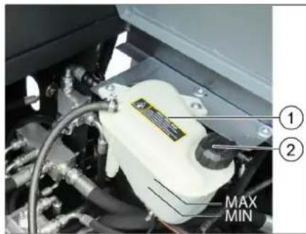
1 Expansion tank for liquid cooling
2 Cap
Check the coolant level in the expansion tank (level between the MIN and MAX marks). Refill the radiator. Check the tightness of the radiator cap and connections.
Checking the lifting cylinder
Start the engine. → Raise the debris container. Switch off the engine. Engage the parking brake. → Install the safety supports for emptying the debris container. → Remove the lifting cylinder's protective cover and ropes. Remove the safety supports. Start the engine. Lower the debris container to the initial position. Switch off the engine.
Replacing the lifting cylinder
Combined garbage bin.
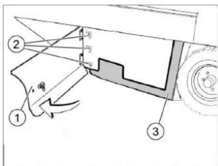
1 Side panel, right 2 Barrel nuts 3 Side seal Open the right side panel using the key. Unscrew the barrel nuts located on the flat locking washer from the side seal. Remove the flat locking washer.
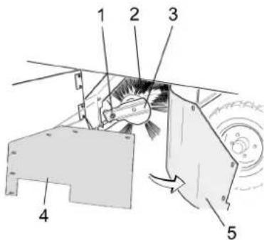
1 Fastening screw of the feeder shaft holder 2 Intermediate gear 3 Feeder shaft holder 4 Flat locking washer of the side seal 5 Side seal Pull off the side seal. → Unscrew the fastening screws of the feeder shaft holder and turn the intermediate device upward. Remove the feeder shaft.
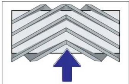
Position of the feeder shaft when installing in the direction of movement (arrow from above)
Note: When installing a new feeder shaft, pay attention to the chain tension.
Install the new feeder shaft. The grooves of the feeder shaft must align with the projections of the guide.
Note: After installing the new feeder shaft, it is necessary to re-adjust the plane of the feeder.
Checking and correcting the plane of the feeder for the feeder shaft
Check the pressure in the tires. → Switch off the suction fan → Place the feeder unit on a flat surface covered with a clean cloth. → Using the control handle, lower the feeder shaft and let it run (approx. 10 s). → Lift the feeder shaft. → Give the device a break. Check the plane of the feeder.
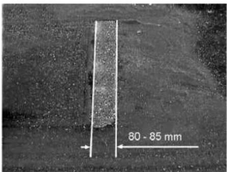
The plane of the feeder should be a uniform rectangle with a width of 80-85 mm.
Adjustment of the feeder profile
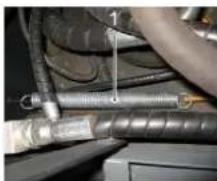
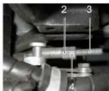
1 Handle
2 Adjusting nut
3 Lock nut
4 Threaded rod
Adjust the position of the profile by rearranging the adjusting screw. Check the flatness of the profile.
Checking and correcting the profile of the side brushes
Check the pressure in the tires. → Lower the side brush using the adjusting screw. → Place the side brush on a flat surface covered with a thin layer of paint. → Manual control of the side brushes (3) forward: the side brush lowers. → Let the side brush run for about 10 seconds. → Raise the side brushes. → Give the machine a forward tilt. Check the flatness of the profile.
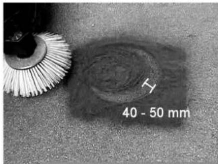
The profile of the side brush should be between 40 and 50 mm.
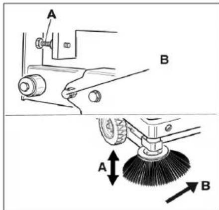
→ Adjust the position of the flatness of the profile using the two adjusting screws. Check the flatness of the profile.
Side brush seals
Check the pressure in the tires. → Raise the debris collection reservoir and secure it with the safety catch.
DANGER
Danger of injury! Always install the safety catch when the debris collection reservoir is raised. Tilt the safety catch upward to empty the raised reservoir and insert it into the holder (safety catch).
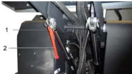
1 Safety catch lever 2 Safety catch
Open the side flap as described in the "Replacing the side brush" section above. Loosen the bolts on the front locking plate. Loosen the 3 screws (SW 13) on the front locking plate.
Press the side seal down (through the hole) until the gap is 1-3 mm from the floor. → Tighten the locking plate. → Repeat the procedure for the other side.
Replace defective safety catches.
Note: Use only safety catches with the same rating.
Declaration of Conformity
We hereby declare that the machine designated below, by its design and construction, as well as in the execution we have put on the market, complies with the applicable essential health and safety requirements of the EU Directives. Any modification not agreed upon with us renders this declaration invalid.
Product designation: Machine with place for operator
Type: 1.186-145.0
Essential EU Directives
2006/42/EC (+2009/127/EC)
2014/30/EC
2000/14/EC
Harmonized standards applied
EN 60335-1
EN 60335-2-72
EN 55012: 2007 + A1: 2009
EN 61000-6-2: 2005
EN 62233: 2008
National standards applied
Applied conformity assessment procedure
Chairman of the Board of Management
S. Reiser
Director Regulatory Affairs & Certification
Authorized employee for document management:
S. Reiser
Alfred Kärcher SE & Co. KG
71364 Winnenden (Germany)
Tel.: +49 7195 14-0
Fax: +49 7195 14-2212
Winnenden, 2022/02/01
Help in case of malfunction
www.kaercher.com/REACH
Warranty
71364 Winnenden (Germany)
Tel.: +49 7195 14-0
Fax: +49 7195 14-2212
Winnenden, 2022/02/01
www.kaercher.com/REACH
Warranty
2006/42/EC (+2009/127/EC)
2014/30/EU
2000/14/EC
2000/14/EC: Annex V
71364 Winnenden (Germany)
Tel.: +49 7195 14-0
Fax: +49 7195 14-2212
Winnenden, 2022/02/01
Troubleshooting
www.kaercher.com/REACH
Warranty
Relevant EU Directives:
2006/42/EC (+2009/127/EC)
2014/30/EU
2000/14/EC
Chairman of the Board of Management
Director Regulatory Affairs & Certification
71364 Winnenden (Germany)
Tel.: +49 7195 14-0
Fax: +49 7195 14-2212
Winnenden, 2022/02/01
www.kaercher.com/REACH
Warranty
2006/42/EC (+2009/127/EC)
2014/30/EU
2000/14/EC
H. Jenner Chairman of the Board of Management

S. Reiser
Director Regulatory Affairs & Certification
Documentation administrator:
S. Reiser
Alfred Karcher SE & Co. KG
71364 Winnenden (Germany)
Tel.: +49 7195 14-0
Fax: +49 7195 14-2212
Winnenden, 2022/02/01
Troubleshooting
www.kaercher.com/REACH
Warranty
Checking the pressure in the envelope
EU Directives complied with:
2006/42/EC (+2009/127/EC)
2014/30/EU
2000/14/EC
Harmonized standards used:
EN 60335-1
EN 60335-2-72
EN 55012: 2007 + A1: 2009
EN 61000-6-2: 2005
EN 62233: 2008
National application standards:
71364 Winnenden (Germany)
Tel.: +49 7195 14-0
Fax: +49 7195 14-2212
Winnenden, 2022/02/01
www.kaercher.com/REACH
Warranty
Maintenance after every 50 operating hours:
2006/42/EC (+2009/127/EC)
2014/30/EU
2000/14/EC
2000/14/EC: Annex V
71364 Winnenden (Germany)
Tel.: +49 7195 14-0
Fax: +49 7195 14-2212
Winnenden, 2022/02/01
www.kaercher.com/REACH
Warranty
In every country, the warranty conditions issued by our responsible distribution organization apply. We will repair any faults on the machine free of charge during the warranty period if they are caused by material or manufacturing defects. In the event of a warranty claim, please contact your dealer or the nearest authorized service center, presenting the proof of purchase.
Function
The sweeping machine works on the principle of blades for collecting dirt.
- The rotating sweeping roller transfers the dirt directly into the designated container.
- The side broom collects dirt from corners and edges of the surface being cleaned and directs it into the path of the sweeping roller.
- The suction fan draws fine dust through the appropriate filter.
2006/42/EC (+2009/127/EC)
2014/30/EU
2000/14/EC
Harmonized standards applied:
EN 60335-1
EN 60335-2-72
EN 55012: 2007 + A1: 2009
EN 61000-6-2: 2005
EN 62233: 2008
National standards applied:
Chairman of the Board of Management
S. Reiser
Director Regulatory Affairs & Certification
Authorized for documentation: S. Reiser
Alfred Kärcher SE & Co. KG
71364 Winnenden (Germany)
Tel.: +49 7195 14-0
Fax: +49 7195 14-2212
Winnenden, 2022/02/01
www.kaercher.com/REACH
Warranty
2006/42/EC (+2009/127/EC)
2014/30/EU
2000/14/EC
Applied harmonized standards:
EN 60335-1
EN 60335-2-72
EN 55012: 2007 + A1: 2009
EN 61000-6-2: 2005
EN 62233: 2008
71364 Winnenden (Germany)
Tel.: +49 7195 14-0
Fax: +49 7195 14-2212
Winnenden, 2022/02/01
| Otklanjanje smetnji | |
| Smetnja Otklanjanje | |
| Urežaj se ne mozePokrenuti | Sedite na sedište vozača, kontaktni prekidača sedišta vozača se aktivira. |
| Punjenje ili zamena akumuladora | |
| Ulije gorivo, ispustite vazduh izsystema goriva | |
| Zamena filtera za gorivo | |
| Zamena predfiltera za gorivo | |
| Proverite i po potrebi popravite system vodova za gorivo, priključke i spojeve. | |
| Obavestite Kärcher servisnu službu. | |
| Motor radi neravnomero | Očistite filter za vazduh ili zamenite filterski uložak. |
| Proverite i po potrebi popravite system vodova za gorivo, priključke i spojeve. | |
| Obavestite Kärcher servisnu službu. | |
| Pregrejan motor Dopunite rashladn | sredstvo |
| Isperite hladnjak | |
| Zategnite klinasto remenje | |
| Obavestite Kärcher servisnu službu. | |
| Motor radi, ali se urežaj kreće sporo ili nikako | Otokočite pozicionu kočnicu |
| Proverite da nema upleteni traka ili petlji. | |
| Obavestite Kärcher servisnu službu. | |
| Pišteci zvuk u hidraulici Sipajte hidral | aulicku tečnost |
| Obavestite Kärcher servisnu službu. | |
| Četke se vrte polako ili se uopšte ne vrte | Papučicu za gas postavite sasvim prema napred (visok broj obrtaja). |
| Proverite da nema upleteni traka ili petlji. | |
| Obavestite Kärcher servisnu službu. | |
| U prostoru Četki je usisna snaga mala ili je uopšte nema | Čišćenje filtera |
| Obavestite Kärcher servisnu službu. | |
| Urežaj diže prašinu Podešavanje b | pčihn zaptivki |
| Ukliguje ventilator. | |
| Očistite filter za prašinu | |
| Zamenite filterske zaptivke | |
| Obavestite Kärcher servisnu službu. | |
| Jedinica za Čišćenje ostavlja priljavžtinu da leži | Ispraznite posudu za nakupljenu priljavžtinu |
| Sasvim zatvorite posudu za priljavžtinu. | |
| Očistite filter za prašinu | |
| Zamenite valjak za metenje. | |
| Naknadno podesite profil metenja | |
| Zamenite zaptivne trake na posudu za priljavžtinu | |
| Uklonite strana tela koja blokiraju valjak za metenje | |
| Obavestite Kärcher servisnu službu. | |
| Posuda za priljavžtinu ne moze da se podigne ili spusti | Ukloniti saigurnosni podupirac sa posude za nakupljenu priljavžtinu |
| Obavestite Kärcher servisnu službu. | |
| Posuda za priljavžtinu se vrti presporo ili se uopšte ne vrti | Obavestite Kärcher servisnu službu. |
| Smetnje u radu s hidraulickimPokretnim delovima | Obavestite Kärcher servisnu službu. |
| Teknički podaci | ||
| KM 170/600 R D Classic | ||
| Podaci urežaja | ||
| Brzina vožnje prema napred km/h 14 | ||
| Brzina vožnje unazad km/h 14 | ||
| Savladavanje uspona (maks.) -- 18% | ||
| Površinski učinak bez bočnih metli m | 2/h 18800 | |
| Površinski učinak sa 1 bočnom metlom m | 2/h 23800 | |
| Površinski učinak sa 2 bočne metle m | 2/h 28000 | |
| Radna širina bez bočne metle mm 1344 | ||
| Radna širina sa 1 bočnom metlom mm 1700 | ||
| Radna širina sa 2 bočne metle mm 2000 | ||
| Stepen zašite, zašićeno od kapajuće vode -- IPX 3 | ||
| Trajanje primene sa punim rezervaorom h 4,5 | ||
| Motor | ||
| Tip | -- Kubota | V1505 (E4B) |
| Tip | -- 4-cilindrični | četvorotaktni dizel motor |
| CO-Emisija u skladu sa postupkom merenja EU odredbe 2016/1628 (stepen V) | g/kWh | 1018,0 |
| Način hlăjenja | -- Hlaadenje vodom | |
| Smer obrtanja | -- Suprotno smeru kazaljke sata | |
| Radna zapremina | cm³ | 1498 |
| Maks. snaga | kW/PS | 18,5/24,8 2300 1/min |
| Akumulator | V, Ah | 12, 72 |
| Radni mediji | ||
| Količina motornog ulja | I | 6 |
| Tip motornog ulja | >25 °C | SAE30, SAE10W-30, SAE15W-40 |
| 0 - 25 °C | SAE20, SAE10W-30 | |
| < 0 °C | SAE10, SAE10W-30 | |
| Hidrauličko ulje | -- Renol HV 46 | |
| Količina hidrauličkog ulja | I | 37 |
| Rashladno sredstvo (SAE J814C) | -- Stilmoil Antifrost | |
| Za mesta podmazivanja koja treba ručno podmazati | Višanamensko mazivo | |
| Posuda za nakupljenu prljavštinu | ||
| Maksimalna visina pražnjenja | mm 1540 | |
| Zapremina posude za prljavštinu | I | 600 |
| Valjak za metenje | ||
| Prečnik valjka za metenje | mm 400 | |
| Širina valjka za metenje | mm 1344 | |
| Broj obrtaja | 1/min | 340 |
| Profil metenja | mm 80 | |
| Bočna metla | ||
| Prečnik bočnih metli | mm 650 | |
| Broj obrtaja (kontinualno) | 1/min | 0 - 63 |
| Gume | ||
| Veličina napred | -- 6.00-8 | |
| Pritisak vizduha napred | bar | 8 |
| Veličina pozadi | -- 5.00-8 | |
| Pritisak vizduha pozadi | bar | 8 |
| Kočnica | ||
| Prednji točkovi | -- mehanička | |
| Zadnji točak | -- hidrostaticka | |
| Filterski i usisni sistem | ||
| Tip - Pljosnati naborani filter | KM 170/600 R D Classic | |
| Broj obrtaja 1/min 2900 | ||
| Površina filtera za finu prašinu m | 2 | 9,1 |
| Nominalni podpritsisak usisnog systemd mbar 18,5 | ||
| Nominalni zapreminski protok usisnog systemd m | 3/h 1650 | |
| Vibracioni system -- Elektromotor | ||
| Okolni uslovi | ||
| Temperatura °C -5 do +40 | ||
| Vlažnost vazduha, bez stvaranja kondenzata % 0 - 90 | ||
| Izračunate vrednosti prema EN 60335-2-72 | ||
| Emisija buke | ||
| Nivo zvučnog pritiska LpA | dB(A) | 82 |
| Nepouzdanost KpA | dB(A) | 3 |
| Nivo zvučne snage LWA + nepouzdanost KWA | dB(A) | 103 |
| Vibracije urežaja | ||
| Vrednost vibracije na ruci | m/s2 | 0,7 |
| Nepouzdanost K | m/s2 | 0,2 |
| Sedište | m/s2 | 0,5 |
| Nepouzdanost K | m/s2 | 0,1 |
| Dimenzije i težine | ||
| Dužina x širina x visina | mm | 2742 x 1904 x 2213 |
| Poluprečnik okretanja udesno | mm | 2525 |
| Poluprečnik okretanja ulevo | mm | 2490 |
| Prazna težina (bez dodatnih sklopova) kg 1695 | ||
| Dozvoljena ukupna težina | kg | 2701 |
| Dozvoljeno opterećenje prednje osovine | kg | 1703 |
| Dozvoljeno opterećenje zadnje osovine | kg | 998 |
| Zapremina rezervaora za gorivo, dizel | l | 26 |
| Zadržavamo pravo na tehnicke promene! | ||

Important: Read these instructions before use.
Original operating instructions, effective for the device and for spare parts, for proper use or for special applications.
Storage
Safety instructions...BG1
Symbols for use...BG1 Symbols for repair...BG1 Instructions...BG1
Disposal of the environment BG 2
Warranty. BG 2
Function BG2
Intended use BG 2
Safety instructions BG 2
Functioning of the functional
elements BG 3
Machine illustration for the weather BG 3 Maintenance elements BG 3
Before starting operation
BG 4
Locking/releasing the trigger sprayer BG 4 Filling the washing machine without its own filling. BG 4 Filling the washing
machine with its own tank BG 4
Starting operation BG 4
General instructions BG 4 Control and maintenance activities BG 4
Operation BG 4
Adjusting the water hardness..BG 4 Starting the device..BG 4 Stopping the device. . . BG 5 Weather mode. BG 5 Emptying the reservoir for the measured amount. .BG 5 Switching off the device... BG 6
Transport. BG 6 Storage/Stopping .BG 6 Connection and disconnection .BG 6
General instructions BG 6 Cleaning. BG 6 Maintenance intervals BG 6 Maintenance activities BG 7
EC Declaration of Conformity. BG 11 Assistance in case of malfunction. BG 12 Technical data BG 13
Safety instructions

Risk of hearing damage. Hearing protection must be worn.
Symbols used in the instructions for use
DANGER
For an imminent danger that could lead to serious injury or death.
WARNING
For a possible dangerous situation that could lead to serious injury or death.
CAUTION
For a possible dangerous situation that could lead to minor injury or property damage.
Symbols on the device

Risk of burns from hot surfaces! Before working on the device, let the device cool down sufficiently.

The work on the device must be carried out with protective gloves.

Risk of injury due to entanglement between moving parts of the device.

Risk of injury from moving parts. Do not reach inside.

Danger! Do not cover the doors or ventilation openings.
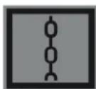
Securing the hinge / bracket for tilting the tap Φ and securing the bracket for fastening
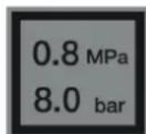
Pressing the buttons (max)
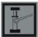
Grips for holding the vehicle hook
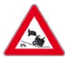
Maximum pressure on the base when approaching with the raised reservoir for changing.
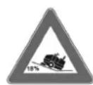
In the direction of travel, drive only on slopes up to 18%
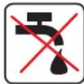
Danger of injury! Do not operate the filter for dry dust.
Displayed
If during unpacking the installation is found to be damaged in transport, notify the store where you purchased it.
The indicated table values provide important information for safe work.
In addition to the indicated instructions, the general safety regulations and accident prevention regulations must be observed.
Instructions for unpacking
Danger
Danger of tipping, danger of crushing!
When unpacking, keep the device in mind!
www.kaercher.com/REACH
Warranty
The warranty conditions published by our distributor company apply in each country. We will repair potential malfunctions of your device free of charge within the warranty period, provided that such malfunction is caused by a material or manufacturing defect. In the event of a warranty claim, please contact your dealer or the nearest authorized service center, presenting the proof of purchase.
Function
The cleaning machine works on the principle of vacuuming.
- The suction turbine creates a vacuum directly in the dirty water tank. - The dirty water is drawn in and passes through the filter, cleaning the surfaces to be vacuumed. - The dirt is collected in the dirt filter with the help of the suction hose.
Intended use
Intended use
Use this cleaning machine only in accordance with the instructions in these operating instructions.
Before using the device, check it for safe condition and operational safety. If the device is not in perfect condition, its use is prohibited. - This cleaning machine is intended for vacuuming dry, non-flammable dusts. - Use of the device in enclosed rooms is not permitted. - The device, on which you sit, must not be used without proper equipment (e.g., seat). - The device may only be used on surfaces that are approved by the manufacturer. - The device may only be used for cleaning purposes in public areas, not for transport of persons or goods. - All openings of the device must be kept closed and protected from water. - The device is not suitable for vacuuming flammable or explosive dusts. - No modifications may be made to the device. - Never vacuum/collect explosive liquids, flammable gases, or solvents! These include petrol, solvents, or fuel oil, which, when mixed with air for vacuuming, can form explosive vapors or mixtures. Additionally, solvents and thinners are not permitted, as they can attack the materials used in the device. - Do not vacuum/collect hot or glowing objects. - The device is only suitable for the surfaces described in the operating instructions. - It may only be used on surfaces that are permitted by the manufacturer. - It is forbidden to use the device in hazardous areas. Work in potentially explosive rooms is prohibited. - Keep a safety distance from the device when using it (risk of explosion/fire).
Safety instructions
DANGER
Danger of tipping! Check the stability of the machine before starting work.
- Asphalt - Industrial floors - Concrete floors - Stone - Pavement
PRECAUTION
Do not worry! We will not leave you, we will be here, we will protect you from the metal beast.
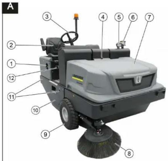
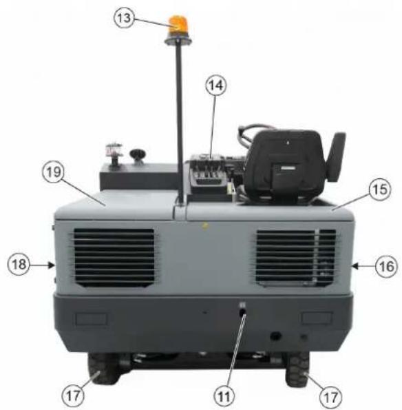
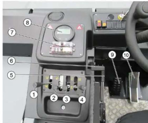
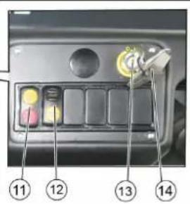
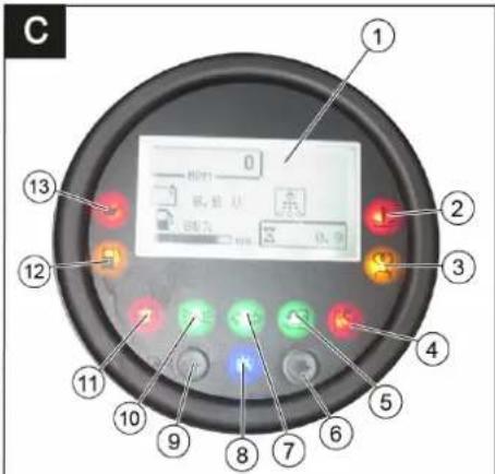
Image of the machine for metal
Figure A
1 Cap of the reservoir 2 Saddle (with contact for saddle preheating)
3 Buzzer 4 Blocking of the channel of the device 5 Blue Spot (optional) 6 Centrifugal separator 7 Channel of the device 8 External metal, separate 9 Pre-chamber elbow 10 Pipes to the metal bath 11 Fixing point for fastening 12 Body plate 13 Lamp for lighting the eye 14 Service elements 15 Channel of the device separate 16 Cover, separate 17 Filling elbow 18 Cover, separate 19 Drain channel (channel of the engine)
Service elements
Figure
1 Control of the metal bath switching on/off 2 Service of the reservoir for heating/cooling 3 Service of the external metal inlet/outlet 4 Service of the reservoir cap opening/closing 5 Locking spring 6 Speed of the motor control knob 7 Preheater 8 Control lamp and switch 9 Switch 10 Lever for movement forward/backward 11 Pre-switch ventilator filter cleaning in the environment: Filter cleaning of the ventilator from the environment or forward: Ventilator on. Environment backward: Filter cleaning on. 12 Pre-switch 13 Spare key switch Position 0: Engine off Position 1: Preheating on Position 2: Engine start 14 Key for the pipes to the metal bath
Control lamp and switch
Figure
1 Indication of the engine speed, filter clogging, battery capacity, number of working hours, indication of the reservoir 2 Signal lamp for the temperature of the cooling water 3 Control lamp of the preheater 4 Control lamp of the reservoir cap for closed drain 5 Signal lamp of the reservoir cap for open drain
6 Fault
Control lamp of the engine fault
8 Indication 9 Fault
10 Control lamp of the working light fault 11 Control lamp of the battery 12 Signal lamp of the fuel reserve 13 Signal lamp for the oil pressure
Battery safety instructions
Locked/unlocked the trigger lock
Battery safety instructions
When working with batteries, always observe the following safety instructions:
| i | Спазаиме указаньама на akymулиора, в льмени- mo за улomреба у в Incмту- цума за ekсплоамацу на празовоземо среемо! |
| Hoceme зашиima за очime! | |
| Дръжme Deцама Нассану om киселени u om akymули- mорu! | |
| Опасносм om ekсплоизу! | |
| Збравявам се оьн, ускру, omkrрumsa севлени u пух- né! | |
| Опасносм om разяжданe! | |
| Пърета пооч! | |
| Указамени заменека! | |
| Изхьрлени! | |
| Pb | Акумулиама за не се xьр- 个项目 в костама за бokлун! |
Danger
Danger of explosion! On the battery terminals, i.e., on both poles, avoid placing tools or similar objects to prevent short circuits.
Danger
Danger of injury! Never touch the poles with your hands. Always wear protective gloves when working on batteries.
DANGER
Danger of fire and explosion!
- Smoking and open flames are prohibited. If batteries are charged, the room must be well ventilated, as highly explosive gases are produced during charging.
Danger
Danger of burns!
- Risk of acid burns on eyes or skin. Rinse immediately with clean water.
- Follow the instructions carefully and consult a doctor if needed.
- The device must be measured with water.
Place the battery and cover it.
Place the battery in the battery compartment. → Keep the battery terminals clean. → Connect the red cable to the positive terminal (+). → Connect the black cable to the negative terminal (-).
Note: Battery terminals and cable clamps should be checked for sufficient protection with protective grease.
Check and correct the battery fluid level.
DENSITY
When filling with battery acid, check the fluid level regularly.
The acid of a fully charged battery at 20°C has a specific gravity of 1.28 kg/l. The acid of a partially discharged battery has a specific gravity between 1.00 and 1.28 kg/l. The specific gravity of the acid must be equal in all cells. Remove all cell caps. → Take a sample from each cell with a hydrometer. The acid sample must be returned to the same cell. → Adjust the fluid level of the cells with distilled water up to the marking. Close the battery. Replace the cell caps.
Charging the battery
Danger
Danger of explosion! Follow the safety regulations when handling batteries. Follow the manufacturer's instructions for use of the charging device.
Danger
The battery must be charged with a suitable charging device.
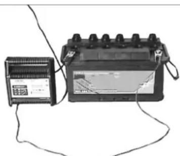
Place the battery in the battery compartment. The battery charger is designed for charging the battery.
Connect the negative terminal of the charger to the negative terminal of the battery. → Place the safety cover and switch on the charger. → The battery should be charged with a low or medium charging current.
Note: When the battery is fully charged, the charger should be disconnected from the mains first, and then from the battery.
Battery removal
Disconnect the positive terminal from the negative terminal (-). Disconnect the positive terminal from the positive terminal (+). Loosen the battery retaining bracket. → Remove the battery from the battery compartment. Dispose of the old battery in accordance with local regulations.
Check the engine oil level and top up if necessary
Danger
Danger of burns!
→ Allow the engine to cool down. → Check the oil level at least 5 minutes after stopping the engine.
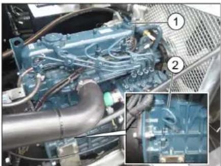
1 Oil filler cap
2 Dipstick
→ Remove the dipstick. → Wipe the dipstick and insert it again. → Remove the dipstick and check the oil level. → Insert the dipstick again.
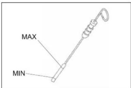
The oil level must be between the "MIN" and "MAX" marks.
If the oil level is below the "MIN" mark, add engine oil. Do not fill above the "MAX" mark. → Tighten the oil filler cap. → Add engine oil.
Oil type: Technical data
Close the oil filler cap. Then let the engine run for at least 5 minutes. Then check the engine oil level.
Engine oil change and oil filter replacement WARNING
Risk of burns! When changing the engine oil and oil filter, the vehicle must cool down while there is still a risk of burns.
Instruction
Drain the engine oil.
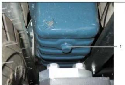
1 Oil drain plug
Prepare a suitable container for at least 10 liters of oil. Then switch off the engine. Open the oil filler cap. Then unscrew the oil drain plug. Then drain the oil.
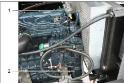
1 Oil filler cap 2 Oil filter on the engine. Then unscrew the oil filter. Clean the area around the filter. Lubricate the gasket of the new oil filter with oil. Install the new oil filter and tighten it by hand. Tighten the oil drain plug with a new gasket. Tightening torque: see Technical Data. Then fill in engine oil. The oil type and quantity for filling are given in the Technical Data chapter.
Close the oil filler cap. Let the engine run for about 30 seconds. Then let it run for at least 5 minutes. Then check the engine oil level. Check for leaks. The old oil must be disposed of at designated collection points.
Cleaning and replacing the air filter
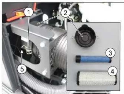
1 Fixing
2 Air filter housing 3 Safety filter 4 Filter element 5 Ventilation opening 6 Locking clips. Then remove the air filter housing. Then remove the filter element. Then clean the inside of the air filter housing. Then remove the safety filter only if it is to be replaced. Then install the new filter element: press it onto the housing, ensuring it fits correctly. Then install the safety filter. Then check the filter element for damage before installation. Then install the cleaned filter element.
Important: A heavily soiled or damaged filter element must be replaced.
If the filter element is replaced, also replace the safety filter.
Important: When replacing the filter element, the safety filter must not be removed unless it is being replaced. Do not allow dirt to enter the intake tract.
Note: The position of the drain plug may vary (see figure).
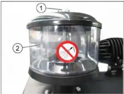
1 Cap nut 2 Centrifugal separator. Unscrew the cap nut from the centrifugal separator. Unscrew the centrifugal separator.
Checking the hydraulic oil level and adding hydraulic oil
INSTRUCTION
The reservoir for the hydraulic oil must not be pressurized. Open the filler cap.
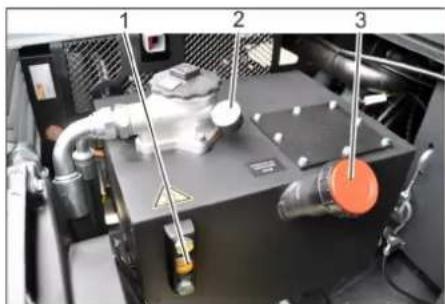
1 Hydraulic oil dipstick 2 Pressure gauge 3 Filler cap, oil filler opening. Check the hydraulic oil level through the sight glass. The oil level must be between the "MIN" and "MAX" marks. If the oil level is below the "MIN" mark, add hydraulic oil. Unscrew the filler cap of the oil filler opening. → Observe the filling range. → Fill with hydraulic oil. Oil type: Technical data. Screw the filler cap back on the oil filler opening.
INSTRUCTION
If the pressure gauge shows increased pressure in the hydraulic system, the hydraulic oil filter must be replaced by Karcher service.
Checking the hydraulic system INSTRUCTION
The hydraulic system may only be repaired by Karcher service.
→ Close the shut-off valve. Start the engine. → Check the hydraulic hoses and connections for leaks.
Checking the surface and the intake
Danger
Danger of burns from hot oil! Allow the machine to cool down for at least 20 minutes.
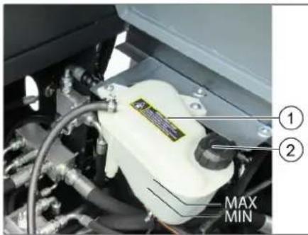
Antifreeze tester
Check the level of the cooling water from the expansion tank (water level between MIN and MAX). → Clean the fins of the radiator. Check the radiator hoses and connections for tightness.
Checking the metal detector
Starting the motor. → Raise the reservoir for the removed metal to the highest position. → The motor must be switched off and the locking catch must be blocked. Install the pre-filter for high pressure. Remove the metal detector tips. → Remove the pre-filter. Starting the motor. Lower the reservoir for the removed metal to the lowest position. The motor must be switched off.
Removing the metal detector
When lowering the reservoir.
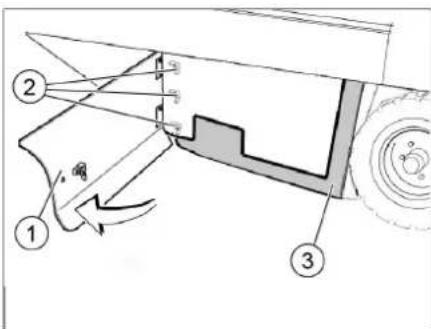
1 Side cover, clearly 2 Curved hook 3 Side tensioning opening. Open the side cover with the key. Unscrew the curved hooks from the clamping lever of the side tensioning and pull the clamping lever.
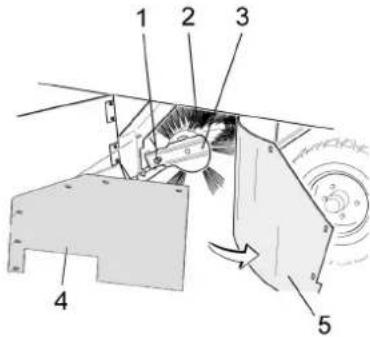
1 Bolt for fastening the metal detector 2 Metal detector 3 Fastening of the metal detector 4 Side tensioning of the clamping lever 5 Side tensioning. Turn the side tensioning upwards. Unscrew the fastening bolts of the metal detector fastening. Tilt the fastening upwards. → Pull the metal detector.
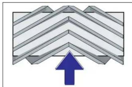
Mounting position of the metal detector in the direction of movement (view from above. Note: When mounting the metal detector, pay attention to the position of the complete brush set with the brush.
→ Mount the metal detector. The bolts of the metal detector must be placed in the supports of the metal detector on the opposite side.
Note: After mounting the metal detector, the detector for the metal must be adjusted again.
Checking and adjusting the metal detector
Check the hose. → Switch off the suction unit. → The metal plate must be covered with a flat and even surface, which is covered with dust or similar, so that it is visible. → Lower the metal detector stand for servicing and let it work (approx. 10 sec). → Raise the metal detector. Drive the device to the stand. Check the metal detector.
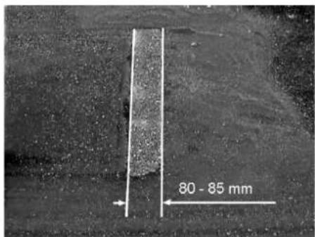
The formed metal detector must form a regular right angle with a width of 80-85 mm.
Adjust the metal detector
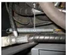
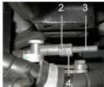
Adjust the reflector for mowing by means of the adjusting bolt. → Check the reflector for mowing.
Checking and adjusting the reflector
For mowing the page metal
Check the tension of the spring. → Pull the metal out of the bank and the page metal with the control posts. → The mowing machine should be moved to an even place, which is covered with dust or debris so that it does not sink. → After servicing the page metal (3) before: The page metal is lowered. Leave the page metal to work for about 10 seconds. → Raising the page metals. Turn the handle on the rear axle. Check the reflector for mowing.
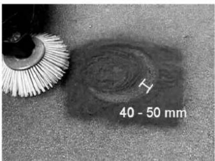
The width of the reflector for mowing should be between 40-50 mm.
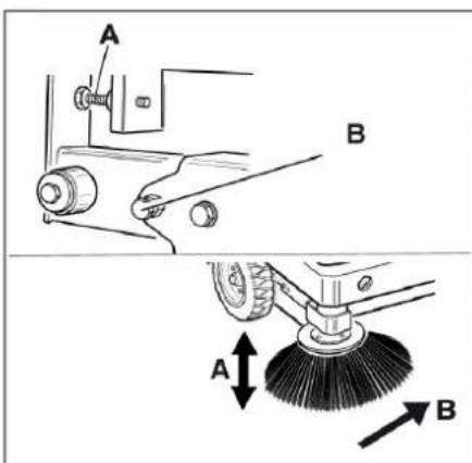
Correct the reflector for mowing with the adjusting bolt. Check the reflector for mowing.
Adjusting the page rollers
Check the tension of the spring. → Raise the reservoir for the removed material and fill it with the pre-set amount.
DANGER
Danger of tipping! The pre-set amount must be set before moving the reservoir for the removed material. Turn the pre-set amount to full stop and place it in the holder (provided).
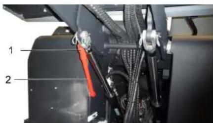
1 Reservoir pre-set amount 2 Pre-set amount Open the page cover as described in chapter "Removing the mowing machine". Fold out the 6-wing nuts of the page lock. Fold out the 3 nuts (SW 13) of the front lock. → Pull out the page rollers from the top opening (upper opening), 3 mm of wire. Then tighten the lock nuts. → Repeat the operation on the other side of the device.
We hereby declare that the machine mentioned above complies with the relevant construction and design, as well as the production method, according to the applicable essential requirements for technical safety and harmlessness of the EC Directives. In case of modifications to the machine that are not coordinated with us, this declaration becomes invalid.
Product: Mowing machine type, on which the CE mark is applied
Tun: 1.186-145.0
Harmonised standards applied:
2006/42/EC (+2009/127/EC)
2014/30/EU
2000/14/EC
Harmonised standards used:
EN 60335-1
EN 60335-2-72
EN 55012: 2007 + A1: 2009
EN 61000-6-2: 2005
EN 62233: 2008
National standards
Conformity assessment method used:
2000/14/EC: Annex V
HnBO Ha wym dB(A)
U3mepeH0: 100
TapaHTnpaHo: 103
IopnncBaunTe Jnca DeiCTBaT OT NMeTo V KaTO PbHOMOuNnHa ynpaBntenHn opraH.


Пьномошник NO ДOKум entaцята: S. Reiser
Alfred Kärcher SE & Co. KG
71364 Winnenden (Germany)
Tel.: +49 7195 14-0
Fax: +49 7195 14-2212
Winnenden, 2022/02/01
www.kaercher.com/REACH
Garantii
Uldised ohutusnouded
△OHT
Toode: Imur-puhkija istmega
Type: 1.186-145.0
Relevant EU directives: 2006/42/EU (+2009/127/EU)
2014/30/EU
2000/14/EU
Chairman of the Board of Management

S. Reiser
Director Regulatory Affairs & Certification
71364 Winnenden (Germany)
Tel.: +49 7195 14-0
Fax: +49 7195 14-2212
Winnenden, 2022/02/01
In case of malfunctions
www.kaercher.com/REACH
Warranty
Chairman of the Board of Management
S. Reiser
Director Regulatory Affairs & Certification
Authorized to compile the documentation:
S. Reiser
Alfred Kärcher SE & Co. KG
71364 Winnenden (Germany)
Tel.: +49 7195 14-0
Fax: +49 7195 14-2212
Winnenden, 2022/02/01
www.kaercher.com/REACH
Warranty
Chairman of the Board of Management

S. Reiser
Director Regulatory Affairs & Certification
71364 Winnenden (Germany)
Tel.: +49 7195 14-0
Fax: +49 7195 14-2212
Winnenden, 2022/02/01
| Pagalba gedimu atveju | |
| Gedimas Šalinimas | |
| Prietaisas nejsijungia | Užimkite vieta vairuotojo sédynèje, aktyvinamas kontaktinis sédynès jungiklis. |
| Jkraukite arba pakeiskite baterija | |
| Jpilkite degalu, išleiskite ora iš degalu sistemos | |
| Pakeisti degalu filtra | |
| Pakeisti pirminj degalu filtra | |
| Patikrinkite ir, jei reikia, suremontuokite degalu tiekimo sistema, movas ir jungtis | |
| Kreipkitës j „Kächer“ clientu aptarnavimo tarryba | |
| Variklis veikia netolygiai | Išvalykite oro filtra arba pakeiskite oro filtro kasetë |
| Patikrinkite ir, jei reikia, suremontuokite degalu tiekimo sistema, movas ir jungtis | |
| Kreipkitës j „Kächer“ clientu aptarnavimo tarryba | |
| Perkaito motoras lpkite aušinamojo | skysćio |
| Išplaukite aušintuvá | |
| Jtempkite trapecinés pavaros dirža | |
| Kreipkitës j „Kächer“ clientu aptarnavimo tarryba | |
| Variklis veikia, tačiu mašina va-ziuja létai arba visai nevažiujoa | Atleiskite stovějimo stabdji |
| Patikrinkite, ar néra apsvijusić juostu ir virviu. | |
| Kreipkitës j „Kächer“ clientu aptarnavimo tarryba | |
| Švilpimas hidraulinène sistemoje lpkite | hidraulinio skysćio |
| Kreipkitës j „Kächer“ clientu aptarnavimo tarryba | |
| Sepečiay nesisuka arba sukasi la-bai létai. | Akseleratorius svirtj nustatykite iki galo j priekj (aukstos apsukos). |
| Patikrinkite, ar néra apsvijusić juostu ir virviu. | |
| Kreipkitës j „Kächer“ clientu aptarnavimo tarryba | |
| Per mažai arba néra siurbimo ga-lios prie šepećio | Filtro valymas |
| Kreipkitës j „Kächer“ clientu aptarnavimo tarryba | |
| Prietaisas dulkëja Šoniniu tarpikliu | reguliavimas |
| ljunkite ortūte | |
| Išvalykite dulkić filtra | |
| Pakeiskite filtro déžës tarpiklj | |
| Kreipkitës j „Kächer“ clientu aptarnavimo tarryba | |
| Šluojami nešvarumai lieka Ištušinkite | dulkić maišelj |
| Visiškai uždarykite nešvarumu talpyklç | |
| Išvalykite dulkić filtra | |
| Pakeiskite besisukanti šepetj | |
| Nustatykite šlavimo plota | |
| Pakeiskite nešvarumu kameros sandarinamajä juostà | |
| Pašalinkite valomojo šepećio blokuotë | |
| Kreipkitës j „Kächer“ clientu aptarnavimo tarryba | |
| Nepakyla arba nenuileidžia ne-švarumu-camera | Pašalinti apsauginë atrama nuo nešvarumu talpyklos |
| Kreipkitës j „Kächer“ clientu aptarnavimo tarryba | |
| Nešvarumu kamera nesisuka arba sukasi labai létai | Kreipkitës j „Kächer“ clientu aptarnavimo tarryba |
| Hidraulíns意見 judinamu da-liu veikimo sutrikaimai | Kreipkitës j „Kächer“ clientu aptarnavimo tarryba |
Technical data
Maximum tilt angle (max.)
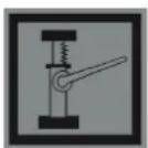
Tilt angle and tilt
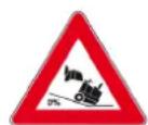
Maximum surface tilt when moving with a hopper.
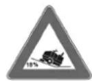
When moving in a straight line, descent on slopes up to 18% is permitted.
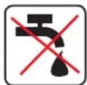
Danger of damage! Do not immerse the pressure hose in liquid.
General instructions
For proper operation and maintenance of the device, it is important to know about the device before you purchase it.
The warning signs and data plates affixed to the device are important instructions for safe operation of the device. Together with the instructions in this operating manual, the general safety rules and accident prevention regulations of the legislative bodies must be observed.
Instructions for unpacking
Danger
Danger to health and safety - risk of injury!
Please return the device to the collection point after use.
∴ m = 3/11
Old devices contain valuable materials that can be recycled. Batteries, oil, and similar materials must not be disposed of with household waste. Therefore, please dispose of old devices using special collection systems.
Instructions for handling components (REACH)
Current information on components can be found at the web address: www.kaercher.com/REACH
Warranty
The warranty conditions issued by our sales company apply in each country. We will repair potential malfunctions of the device free of charge within the warranty period, provided that they are caused by material or manufacturing defects. In the event of a warranty claim, please contact your dealer or the nearest authorized Customer Service center with the purchase receipt.
Intended use
The machine is designed for cleaning and collecting dirt into a reservoir.
- The rotating brush directs dirt into the collection reservoir. - The brush lifts dirt from the surface and directs it into the collection container. - The brush is driven by a suction motor through a filter.
Proper use
Use the cleaning machine only in accordance with the operating instructions.
→ Before use, check the condition and safety of the device and accessories. If the device or accessories are in an unsafe condition, they must not be used. - This is an electrically powered machine intended for cleaning dirty surfaces outdoors. - Operation in enclosed spaces is prohibited. - Devices without proper safety equipment (installed at the factory) are not permitted for use in road traffic conditions. The device may be used on public roads only after prior individual approval by the relevant authority. - All covers of the device may only be removed in areas protected from the weather. - Use of the device for collecting flammable liquids is prohibited. - Modifications to the device are prohibited. - Use in potentially explosive atmospheres, flammable gases, as well as undiluted acids and solvents is prohibited! This applies to gasoline, paint thinner, and solvents that can create explosive gases or mixtures with the suction air, as well as acetone, undiluted acids, and solvents, as they can damage the device material. - Do not allow children or other persons to use the device. - The device is intended only for work on surfaces specified in this operating manual. - The device may only be moved on surfaces approved for use with cleaning machines by the company management or their representative. - Storage in unsafe places is prohibited. Use of the device in potentially explosive atmospheres is prohibited. - General safety rule: Do not allow the device to come into contact with flammable liquids (explosion/fire hazard).
Surface cleaning
DANGER
Danger! Check the surface before each use.
- Switch - Fuse - Main (main) switch - Circuit breaker - Button
PROTECTION
Danger of electric shock! Do not allow the device, wires, or hoses to come into contact with the user.
A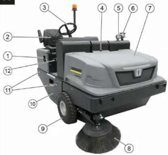
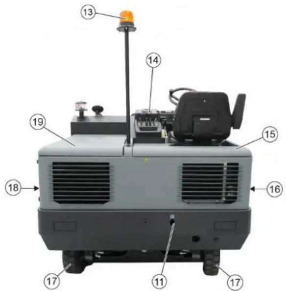
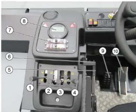
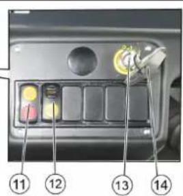
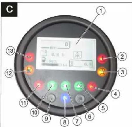
Image of the main machine and device elements
HANDLE A
1 Reservoir cover 2 Backrest (with contact switch) 3 Control wheel 4 Locking of the device cover 5 Blue Spot (optional) 6 Built-in separator 7 Device cover 8 Right side cover 9 Front wheel 10 Inlet opening for the pump, device 11 Seat cushion 12 Nameplate 13 Flashing beacon 14 Control elements 15 Right device cover 16 Right cover 17 Rear wheel 18 Left cover 19 Left cover (left cover)
HANDLE
1 Control lever for raising/lowering the suction foot 2 Control lever for the reservoir for collecting liquid raising/lowering 3 Control lever for raising/lowering the side brushes 4 Control lever for opening/closing the reservoir cover 5 Parking brake 6 Adjustment knob for the pump output 7 Pedal for the pump 8 Control indicators and displays 9 Brake pedal 10 Forward/backward drive lever 11 Switch for the filter shaker and filter cleaning. Middle position: filter cleaning and shaker on. Front position: shaker on. Rear position: filter cleaning off 12 Sound signal switch 13 Ignition lock. Position 0: pump off. Position 1: ignition on. Position 2: start the pump 14 Access key to the cylinder head 1
Control indicators and displays
HANDLE
1 Signal lamp: Number of pump revolutions, filter cleaning active, battery charge level, low water level indicator 2 Signal lamp: Water temperature, cooling 3 Control indicator for playback 4 Control lamp for closed reservoir cover for collecting liquid 5 Signal lamp for open reservoir cover for collecting liquid 6 Not used 7 Signal lamp for indicating revolutions. Not used 8 Indicator for switched-off ventilation fan 9 Not used 10 Control lamp for working light. On 11 Indicator for battery charging 12 Signal lamp for oil reserve 13 Signal lamp for oil pressure
Work mode
Lock/release the parking brake
Bend the throttle lever towards yourself when moving the machine forward. Fix the throttle lever in this position when moving forward.
Moving the machine without its own drive
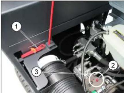
1 Special tool 2 Bolt of the idle stroke screw 3 Adjusting the cover. → Turn the idle stroke screw (left-hand thread) of the right pump 180° (counterclockwise). Use the special tool.
WARNING
The special tool (reference 2 of the kit) is located in the tool kit on the machine frame, near the idle stroke mechanism.
CAUTION
Do not move the machine at speeds higher than 10 km/h.
After moving the machine, turn the idle stroke screw of the right pump back clockwise to the stop.
Moving the machine with its own drive
After moving the machine, turn the idle stroke screw of the right pump back clockwise to the stop. Use the special tool.
Putting into operation
General instructions
→ Before operation, read the operator's manual of the device carefully and follow the safety instructions. Install the machine on a flat surface. → Pull out the locking pin. Fix the throttle lever system.
Inspection and technical maintenance
Daily before starting operation
→ Check the fuel level in the fuel tank. → Check the oil level in the engine. → Check the coolant level. → Check the tire pressure. → Check the belts for cracks and signs of wear, and that they are properly tensioned. → Check the wheels for damage and wear, and that they are properly tightened. → Check the centrifugal separator and the filter elements, clean if necessary. → Check the condition of all control elements. → Check the device for leaks. → Perform a fuel filter change using the fuel filter key.
Instructions: See detailed instructions in the "Maintenance and Technical Service" section.
Protection against freezing
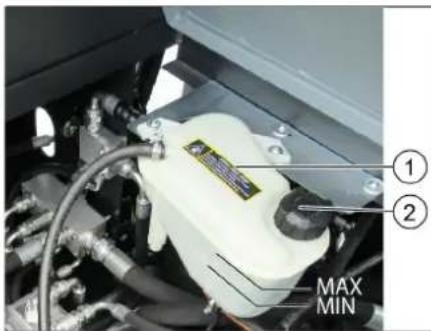
1 Radiator coolant expansion tank 2 Filler cap → To prevent freezing, check that there is enough antifreeze in the cooling system.
Refueling
Caution!
Explosion hazard!
It is necessary to use only the fuel specified in the operating instructions. Refueling with closed devices is prohibited. It is forbidden to spill fuel on hot surfaces. Make sure that fuel does not get on hot surfaces. Turn off the engine. Close the lockable fuel tank cap. Refuel with diesel fuel. When refueling, use only winter diesel fuel, otherwise, due to the condensation of diesel fuel components, problems may arise during operation. Open the fuel tank cap and close the tank cap. Close the fuel tank valve.
Operation
Adjusting the fuel injection pump
→ Pull out the adjusting lever. → Move the lever, release the lever and it will lock into place. → By moving the lever forward/backward, check its operation.
Starting the device
ATTENTION
→ Make sure that the levers are in the neutral position. All 4 control levers are in the middle position. Do not press the accelerator pedal during start-up! → The device is equipped with a contact switch. When the switch is turned on, the device turns on. → The start-up sequence is automatically controlled by the fuel filter.
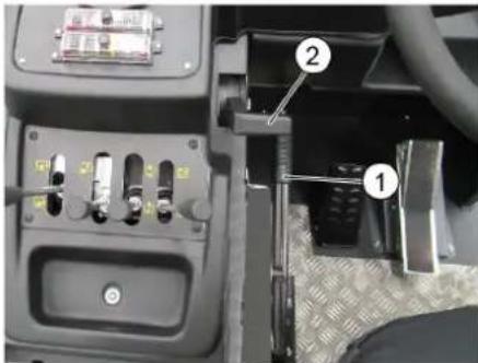
1 Stop lever 2 Speed control knob
Pdabra3y
Engage the clutch on the operator's seat. Engage the parking brake system. → Turn the knob to set the speed to 75% of maximum effort. Insert the ignition key. → Turn the key to the pre-heat position (position). Wait for the glow plug indicator to light up. → When the glow plug indicator goes out, turn the key to the start position (engine start) and hold until the engine starts (max 10 seconds). Release the key. The key returns to the ON position. → If the ambient temperature is below 0°C, before starting work, warm up the engine at low speeds.
Instruction
If the engine does not start, repeat the start.
Refueling
SAFETY
Danger of serious accidents!
Moving with the bucket raised is prohibited!
CAUTION
Danger of tipping!
→Before moving or operating the machine, read the manual carefully. → Press the accelerator pedal gently and smoothly. Do not make sudden changes in speed when going from forward to reverse or on slopes.
Pedal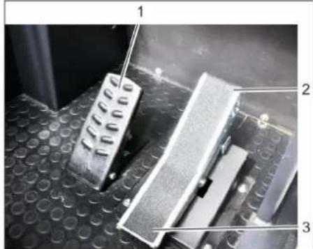
2 Accelerator pedal "Forward" 3 Accelerator pedal "Reverse" → Move the throttle lever fully forward (engine speed). Press and hold the brake pedal. Release the parking brake → Press the accelerator pedal smoothly. Use the throttle to adjust the travel speed.
Driving forward
→Press the forward pedal smoothly.
→ Press the lever back. Do not forget to instruct other persons if necessary. → Press the pedal smoothly back.
Movement characteristics
With the help of the accelerator pedal, the speed can be adjusted steplessly. Avoid sudden pressing of the pedal, so the entire system may be overloaded. → For high power during overtaking, change the pressure on the pedal smoothly.
Braking/Stopping
→ After releasing the movement pedal, the device stops automatically. → For a braking effect or in extreme cases, press the brake pedal.
Additional gear
Do not drive over objects or unclosed obstacles and do not damage them.
Overcoming fixed obstacles higher than 70 mm:
Fixed obstacles should be overcome only using the appropriate ramp. Overcoming obstacles up to 50 mm high: → The obstacles should be passed carefully, moving forward at low speed.
Cleaning
CAREFULLY
Do not use the device if the mechanism is damaged or if it does not operate correctly.
Note: To achieve optimal performance, it is necessary to adjust the amount of movement according to the conditions of use.
Note: The filter for the manual pump is automatically cleaned every 10 minutes.
Note: When working with the pump, the filter must be cleaned regularly. For this purpose, it is recommended to clean the filter for the manual pump regularly.
Clean the filter for the manual pump by pressing the filter cleaning button.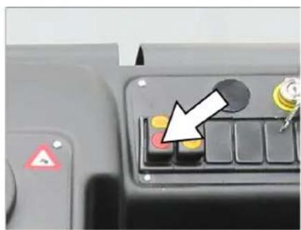
Control lever
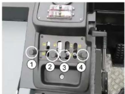
1 Cylinder brush: raise (forward) / lower (backward)
2 Recovery tank: lower (forward) / raise (backward) 3 Brush height: lower (forward) / raise (backward) 4 Tank cover: open (forward) / close (backward)
Dry cleaning
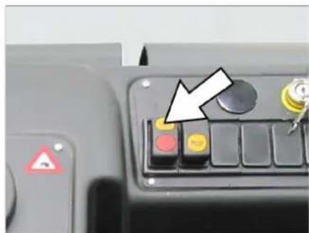
→ Press the switch.
Control lever for the recovery tank (4) forward: The tank cover opens. Note: The green indicator lights up. → For floor cleaning: Control lever for the cylinder brush (1) forward: The cylinder brush is lowered and starts. → For brush cleaning: Control lever for the side brushes (3) forward: The brush is lowered.
Cleaning with dry or wet floor
Press the switch.
Control lever for the tank cover (4) forward: The tank cover opens. Note: The green indicator lights up. → For floor cleaning: Control lever for the cylinder brush (1) forward: The cylinder brush is lowered and starts. → For brush cleaning: Control lever for the side brushes (3) forward: The brush is lowered.
Spare reservoir for milk
DANGER
Danger of injury! Before emptying the reservoir for milk, shut off the milk supply.
DANGER
Danger of electric shock! Never touch the electrical system or mechanical system when the reservoir is empty. Do not stand under the reservoir.
DANGER
Danger of tipping! Before emptying, secure the machine on a level surface.
WARNING
Danger of injury and damage! Before emptying, disconnect the power supply and wait until all moving parts have stopped.
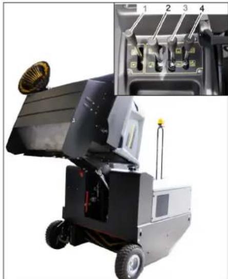
To lower the milk tank, the milk agitator, and the milk pump, move the control lever (1 and 3) backward. → Close the reservoir valve, move the control lever (4) backward. Note: The red indicator light is on. → To empty the reservoir for milk collection, move the reservoir control lever for milk collection (2) backward. → Then drive to the milk collection reservoir. Secure the parking brake. → To open the reservoir valve, move the reservoir valve control lever (4) forward. Empty the milk reservoir. Note: The green indicator light is on. → To close the reservoir valve, move the reservoir valve control lever (4) backward and lock it in the end position. Note: The red indicator light is on. Release the parking brake. → Then drive away from the milk collection reservoir. → To lower the milk collection reservoir into the end position, move the reservoir control lever for milk collection (2) forward.
Turn off the device
→ To lower the milk tank, the milk agitator, and the milk pump, move the control lever (1 and 3) backward. → Close the reservoir valve, move the control lever (4) backward. → Fully move the control lever to the rear position. → Press and hold the brake pedal. Secure the parking brake. Turn the ignition key to position "0" and remove it from the lock.
Transportation
DANGER
Danger of injury from tipping! When transporting, pay attention to the device.
Turn the key to position "0" and pull it out of the lock. Engage the parking brake system. Attach the device to the mounting points (4 pcs) using the appropriate bolts, ensuring it is secure. Secure the device by placing it under its wheels. When transporting the device in vehicles, take into account the place of state standards aimed at protecting against tipping and overturning.
Storage and decommissioning
DANGER
Danger of injury and damage!
When storing, take into account the device. Place the device on a flat surface in a dry and frost-protected place. Cover it to protect from dust. To avoid damage from moisture, rain, and snow, and to prevent corrosion. Turn the key to position "0" and pull it out of the lock. Engage the parking brake system. Drain the water from the system to prevent freezing. Add antifreeze to the water to cool it.
If the machine is not used for a long time, follow the following instructions:
Clean the device inside and out. Change the engine oil. Disconnect the negative battery terminal if the device will not be used for more than 4 weeks. Charge the battery approximately every two months. Cover the battery and protect it from short circuits.
Additional technical maintenance
General instructions
DANGER
Danger of injury! Do not operate the device without proper training.
All covers of the device can only be opened in places protected from water splashes.
Repair work may only be carried out by authorized service centers or specialized personnel who are familiar with all important safety regulations. The device used commercially must be checked for safety in accordance with VDE 0701. Install the device so that it is stable on a level surface. Turn the key to position "0" and pull it out of the lock. Engage the parking brake system.
Cleaning
DANGER
Danger! Do not allow the device to be immersed in water or exposed to water jets under high pressure (danger of short circuit and electric shock).
Device interior is protected!
Danger! Wear protective mask against dust and eye protection.
→ Rinse the device thoroughly. Blow out the device with compressed air. Clean the outside of the device using a mild detergent and a soft damp cloth.
Note: The use of aggressive cleaning agents is prohibited.
Maintenance frequency
Note: The operating manual informs about the timing of maintenance.
Maintenance is carried out by the customer
Note: All maintenance work on the customer side must be carried out by qualified personnel. In case of any issues, you can contact a specialized trade organization of the Karcher company.
Maintenance:
→ Check the filling level of the fresh water tank. → Check the condition of the mats and replace if necessary. → Check the cooling air inlet.
→ Check the pressure in the hoses. → Check for leaks and damage, presence of cracks, and wear. → Check the wheels for cracks and wear. → Check the centrifugal separator and blow it out if necessary. → Check the condition of all control elements. → Check the device for damage. → Perform the filter cleaning using the filter cleaning button.
Maintenance by service personnel:
→ Check the fuel filter. Clean the water radiator. Clean the hydraulic oil radiator. → Check the hydraulic system. → Check the hydraulic oil level. → Check the drive belt. → Check the hoses for leaks and replace if necessary. → Check and lubricate the reservoir cap.
Maintenance parts that wear out:
Replace or repair damaged parts. Use only original spare parts. Replacement must be performed by qualified personnel.
Instructions: See section "Maintenance".
Maintenance must be performed by qualified service personnel.
Maintenance every 50 operating hours:
→ First maintenance must be performed according to the maintenance schedule of the service department.
Maintenance after 250/500/1000/1500/2000 operating hours:
→ Maintenance must be performed according to the maintenance schedule of the technical service.
Note: To preserve warranty rights, all technical and preventive maintenance work during the warranty period must be carried out by the authorized service department of Kärcher in accordance with the maintenance brochure.
Preventive maintenance
PREPARATION:
Install the spare nozzle on the nozzle holder. → Turn the spare nozzle to position "0" and pull it out of the holder. The spray lance system is now locked.
General safety instructions SAFETY
Danger of injury? Keep hands away from the rotating brush when the machine is in operation.
1. Pull the spare brush out of the holder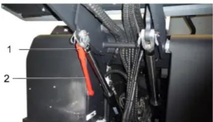
→ Pull the spare brush upward out of the holder for cleaning and reinsert it into the holder (spare).

Be careful not to allow motor oils, grease, diesel fuel, and gasoline to enter the environment. Be careful to protect the soil and dispose of used oils properly, without harming the environment.
Safety instructions for batteries
When working with batteries, observe the following safety precautions:

Follow the instructions on the battery, in the user manual, and in the device's operating instructions!
Wear eye protection!

Do not allow children to access electrical tools and batteries!

Explosion hazard!

It is forbidden to create sparks, open flames, or sources of ignition near the battery!

Chemical burn hazard!

First aid!

Precautionary labeling!
| Уmunizаця! | |
| Pb | He bukuδamu akumyllumop y konmeiHep对不起 smimma! |
Caution!
Explosion hazard! Do not place tools or other objects on the battery, on the terminals, or on the connecting elements.
Caution!
Electrical hazard! Never touch live parts. Before working with the battery, hands must be washed.
Safety warnings and instructions!
- Charging the battery produces hydrogen gas, which can explode if ignited. Before charging, ensure good ventilation. If gas is emitted during charging, ventilate immediately.
DANGER!
Safety warnings for liquid!
- If electrolyte splashes into eyes or onto skin, rinse with plenty of clean water.
- After that, immediately consult a doctor. Use protective gloves.
Install the battery and connect it
Remove the battery
Disconnect the negative (-) terminal first. Then disconnect the positive (+) terminal. Hold the battery firmly. → Remove the battery from the battery holder. Dispose of the battery according to applicable regulations.
Check the oil level and quality
DANGER!
Risk of burns!
→ Let the engine cool down. Check the oil level in the engine only after at least 5 minutes after stopping the engine.
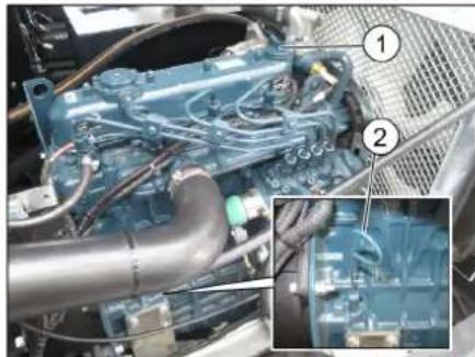
1 Oil filler cap 2 Oil level indicator
→ Unscrew the oil filler cap. → Insert the dipstick and then remove it again. Unscrew the oil filler cap. Remove the dipstick. Reinsert the dipstick. Check the oil level.
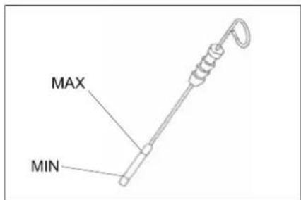
-The oil level must be between the "MIN" and "MAX" marks. -If the oil level is below the "MIN" mark, add oil. -Do not fill oil above the "MAX" mark. Unscrew the oil filler cap. Add engine oil. Install the oil filler cap. Wait 5 minutes. → Check the oil level in the engine.
Fill the engine with oil and close the cap.
△WARNING
Fire hazard!
→To protect the engine oil and the engine oil filter, run the engine until the fire hazard is no longer present.
Indicator
The engine oil change is indicated by the oil pressure indicator.
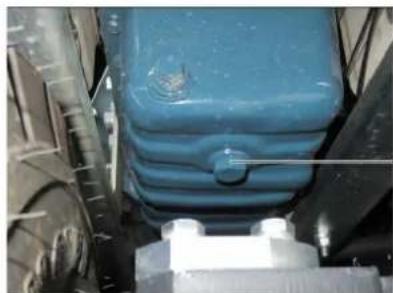
1 Oil filler cap →Prepare at least 10 liters of oil.
→ Remove the oil filler cap. Unscrew the oil drain plug. Drain the oil.
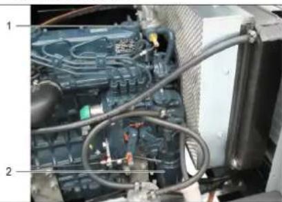
1 Oil drain plug 2 Engine oil filter → Remove the oil filter. → Clean the sealing surfaces. → Before installation, lubricate the sealing ring of the new oil filter with oil. Install the new oil filter and tighten it by hand. Screw in the drain plug with a new sealing ring. Tightening torque: ... with engine oil. Oil grade and fill level are specified in the "Technical Data" section. Close the oil filler cap. → Let the engine run for about 30 seconds. Wait 5 minutes. → Check the oil level in the engine → Check for leaks. → Top up the oil according to the operating instructions.
Cleaning the air filter
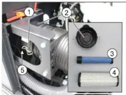
1 Lock 2 Air filter housing 3 Spare filter element 4 Filter element 5 Ventilation opening facing down Unlock → Remove the air filter housing. Remove the filter element. → Clean the inside of the air filter housing. The spare filter element should only be removed for replacement. Clean the filter element: On a hard surface, tap it and blow it out with compressed air (max. 30 psi (2 bar)).
→ The sealing surface and the filter element must be clean and undamaged. Insert the cleaned filter element. Important: A heavily soiled or damaged filter element must be replaced. → When replacing the filter element, also replace the spare filter element. Important: The replacement interval for the filter element and the spare filter element must not be exceeded under any circumstances.
Indicator: Installation position - ventilation opening facing down (see figure).
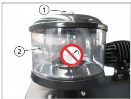
1. Unscrew the cap. 2. Remove the separator. To remove the cap, turn it counterclockwise. Clean the separator.
Check the oil level and top it up if necessary.
The oil reservoir must not be empty. Open the filler cap.
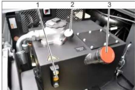
1. Unscrew the oil filler cap.
2. Check the oil level with the dipstick.
→ Check the oil level in the correct system at the sight glass. - The oil level must be between the "MIN" and "MAX" marks. - If the oil level is below the "MIN" mark, add oil. Unscrew the filler cap. Clean the filling area. → Add the correct oil. Oil type: see Technical data. → Screw the filler cap back on.
NOTICE
If the oil pressure drops below the minimum, contact Karcher customer service to replace the oil pressure filter.
Check the main unit
Technical maintenance of the main unit must only be carried out by customer service.
Secure the machine. Start the engine. → Check the oil level and the tightness of the connections.
Checking and maintaining the oil cooler
DANGER
Danger of burns! Let the engine cool down for at least 20 minutes.
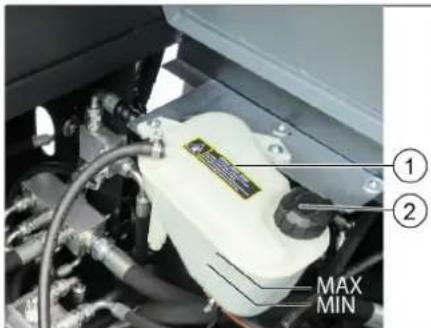
1. Coolant reservoir of the oil cooler
2 Drain plug
→ Check the coolant level in the expansion tank (between the MIN and MAX marks). Inspect the radiator hoses. → Check the radiator cap and the tightness of the connections.
Check that the oil level is correct
Start the engine. → Open the drain valve for collecting used oil. Turn off the engine. Secure the hood in the open position. Install the drain plugs in the drain valve. → Remove the oil filter, oil drain plug, and gasket that were installed. → Remove the drain plugs. Start the engine. Open the drain valve for collecting used oil. Turn off the engine.
Check that the oil level is correct
With the drain valve open for collecting used oil.
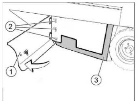
1 Cover
2 Lock nut with a slot for opening the right side of the cover with a key. → Unscrew the lock nuts located on the flat washer, from the bolt, and remove the flat washer.
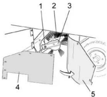
1 Oil filler cap
2 Oil filler plug.
3 Oil filler plug with a handle
Installing the oil filler cap
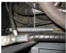
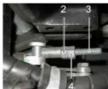
1 Handle
2 Adjusting nut
3 Lock nut 4Threaded plug Adjust the position of the oil filler cap by repositioning the adjusting nut. → Check the tightness of the oil filler cap.
Checking and correcting the fuel level profile, if necessary.
→ Check the pressure in the tires. → Inflate the tires using the control valve. → Install the fuel filter, check the fuel level, cover the fuel tank cap or close it. The control valve for the tires (3) forward: it lowers. → Let the tires inflate for about 10 seconds. Remove the tire valve. → Let the device cool down. → Check the fuel level.
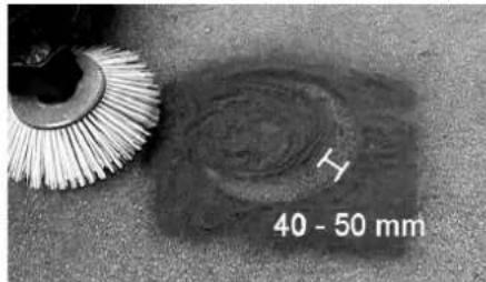
Check the fuel level visually, it should be between 40 and 50 mm.
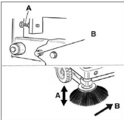
Adjust the position of the fuel level sensor using the adjusting screws. → Check the fuel level.
Install the tire valve
→ Check the pressure in the tires. → Lift the reservoir for collecting condensate and secure it with the locking pin.
DANGER
Danger of injury when lifting the reservoir for collecting condensate. Secure it with the locking pin. → Lift the locking pin and insert it into the hole on the reservoir and put it in the holder (locking pin)
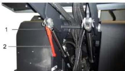
1 Holder for locking pin
2 Locking pin
Open the valve, as described in the chapter "Filling the fuel". Loosen the lock nut on the adjusting screw. Loosen the screw (SW13) on the front lock washer. → Press the valve stem (if necessary) until its edge protrudes 1-3 mm from the valve. → Tighten the lock washer. → Repeat the procedure on the other side of the distributor.
Check the pressure in the tires
Install the fuel filter, check the fuel level, check the surface. → Connect the device to check the pressure in the tires. → Check the pressure in the tires, if necessary, adjust the pressure. Information about the permissible pressure level in the tires is in the chapter "Technical Data".
Checking/Replacing the fuel filter
△WARNING
Hebe3neKa mpaemy6aHHn!
When working with a device that has been properly installed, wear a mask to protect against dust. Follow the safety instructions carefully and keep the device away from children.
Clean the fine dust filter by pressing the cleaning button. → Empty the dirt collection reservoir.
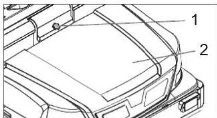
1 Locking buttons for the device 2 Locking button → Press the locking button. To do this, turn the screw with the slot using a screwdriver. Pull out the locking button.
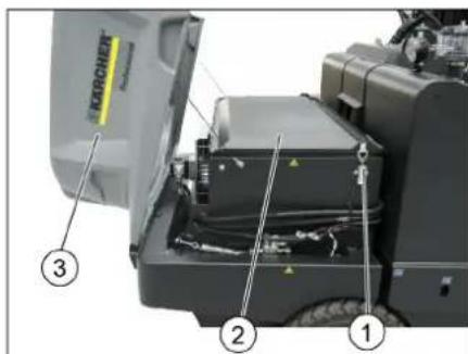
1 Lock, filter cover (2x) 2 Filter cover 3 Locking button → Open the filter cover.
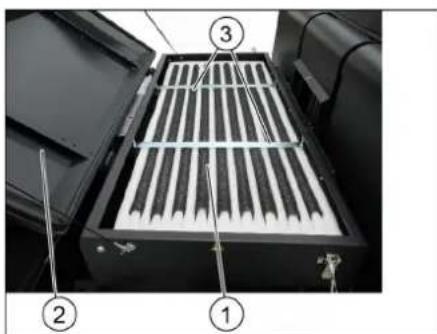
1 Fine dust filter 2 Filter cover 3 Cross bars
Open the filter cover. → Check the fine dust filter, and if necessary, clean or replace it.
Note
Replacing the fine dust filter is only allowed according to the Karcher service instructions. Install and secure the filter cover.
Check and adjust the V-belt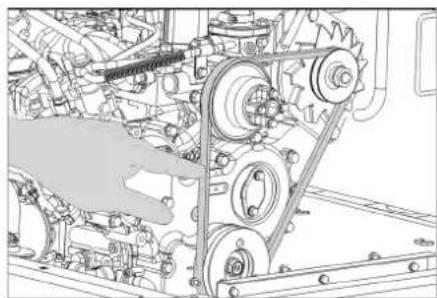
The V-belt, when pressed with 10 kg, should sag approximately 7-9 mm.
→ The V-belt tension is adjusted by the service department.
Replace the fuses
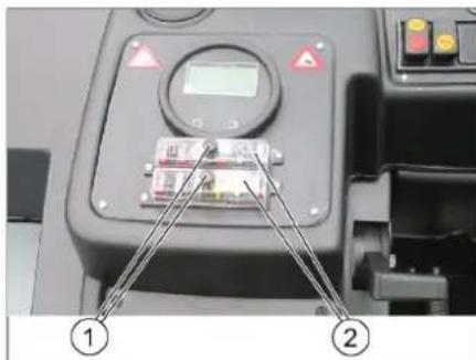
1 Nut with knurling 2 Fuse cover → Unscrew the nut with the knurled nut. Open the fuse cover. → Check the fuses. Replace defective fuses. Note: Use only fuses with the same rating. → Check the fuses.
Application of the cleaning method
Output: 100
Guaranteed: 103
Persons who signed: under name and under authority of management.


Authorized representative for customer service:
S. Reiser
Alfred Kärcher SE & Co. KG
71364 Winnenden (Germany)
Tel.: +49 7195 14-0
Fax: +49 7195 14-2212
Winnenden, 2022/02/01
Additional information on malfunctions
.5
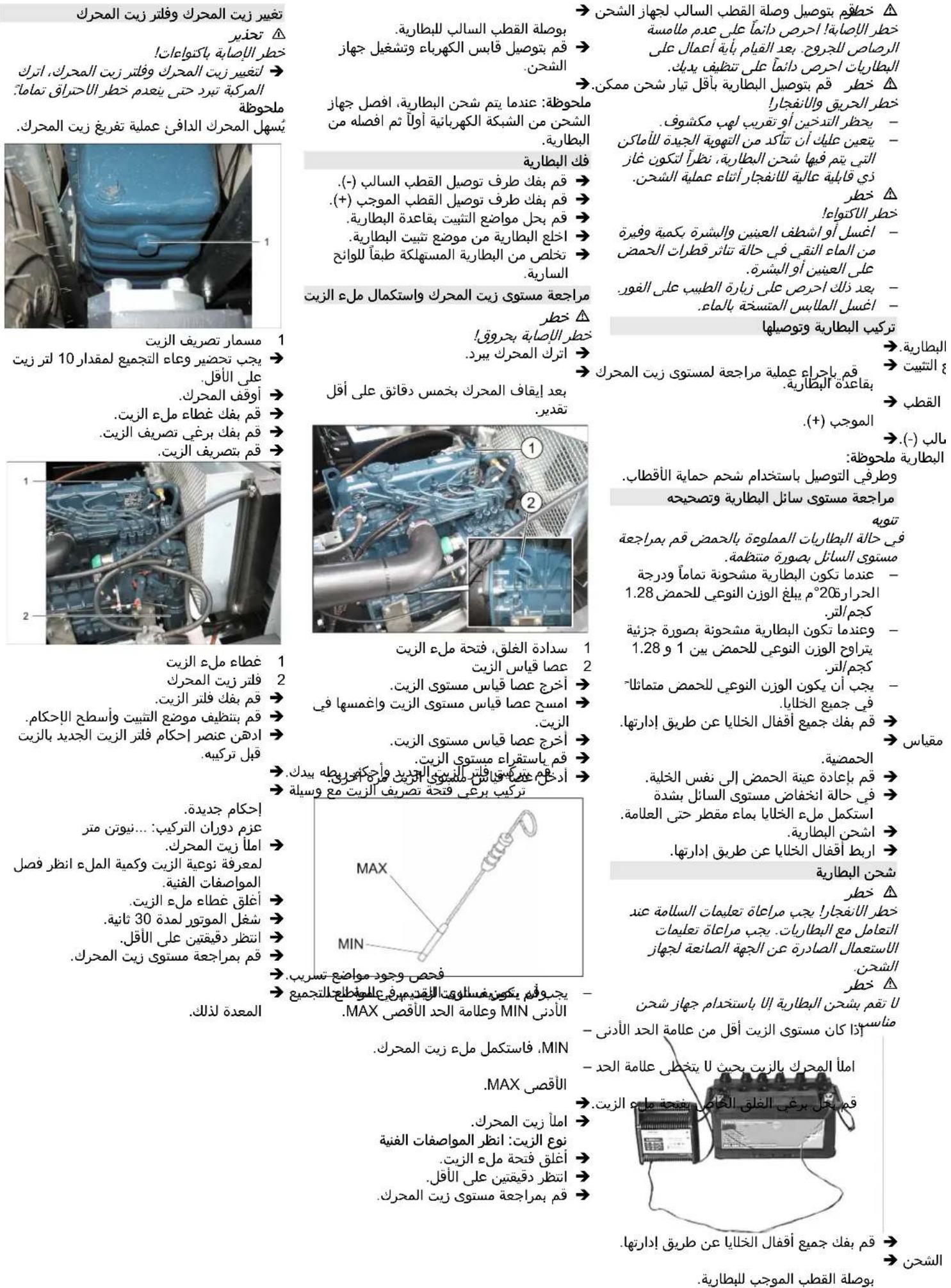
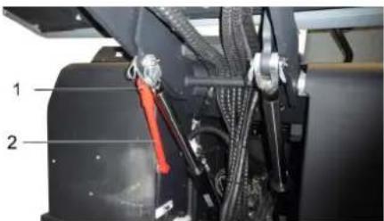
2
U/
16 ÷ Δ
1.22 9 a loll, 2.28
Therefore, the area of triangle OBC equals the area of triangle ABC plus the area of triangle BOC.
- |x - 2| = 5/2 ; |y - 3| = 3/2
→
(5) (x, y) = (ab, (5/2)a)
2Δ
1
→
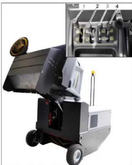
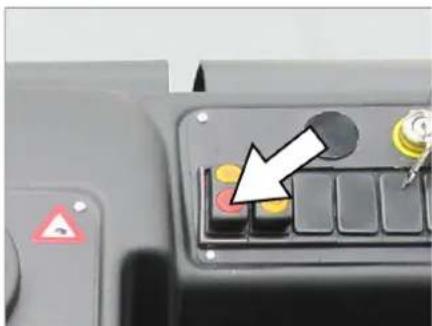
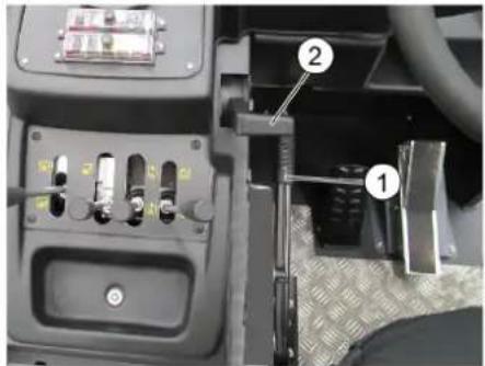
4 ≤ a2
∴ SΔOBC = SΔBOC + SΔCBA
∴ a // | a - 1 | . c

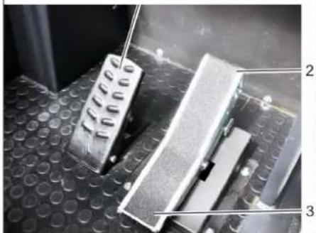
2021/11/20 17:43
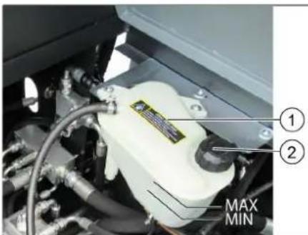
2
#
jlll 1
jllllaeaalbae1jz
aaiu 9 g jj jj pi aaa all jx p9
ploW as JUJoo aeaal Cw w st
.
jglzll Jusw
a
acg,0 w/1/1/1 511
Jaeu//glj/4gau>csu
.aaalgogall
alaccl/2g9//aw/g,dcbasla/0c
1
1ic au 12aal /5ci>1 cliaa 29jo/4g2//
jgl//Juei jie/ jiu/ 2000 oJlao

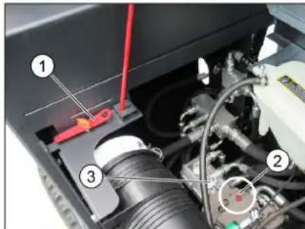
- ρ ( σa + l1 σ12 + σ2 σ22 )
2
4
c/d + x = 0
lorigin : y = -9/x
- g : l ≤ 0
(REACH)
Register your product and benefit from many advantages.
www.kaercher.com/welcome ★★★★★
Rate your product and tell us your opinion.
www.kaercher.com/dealersearch
Alfred Kärcher SE & Co. KG
Alfred-Karcher-Str. 28-40
71364 Winnenden (Germany)

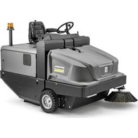
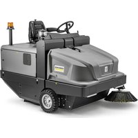
- CONTENTS
- SAFETY INSTRUCTIONS
- SYMBOLS IN THE OPERATING INSTRUCTIONS
- DANGER
- WARNING
- CAUTION
- UNLOADING TIPS
- DO NOT USE A FORKLIFT
- DRIVE MODE
- APPLIANCES WITH COMBUSTION ENGINE
- MACHINES WITH DRIVER CABIN
- NOTICE
- ACCESSORIES AND SPARE PARTS
- ENVIRONMENTAL PROTECTION
- NOTES ABOUT THE INGREDIENTS (REACH)
- WARRANTY
- FUNCTION
- PROPER USE
- SUITABLE SURFACES
- △DANGER
- OPERATING AND FUNCTIONAL ELEMENTS
- ILLUSTRATION OF SWEEPER OPERATING ELEMENTS
- ILLUSTRATION A
- ILLUSTRATION
- INDICATOR LAMPS AND DISPLAY
- BEFORE STARTUP
- LOCK/ RELEASE PARKING BRAKE
- MOVING SWEEPER WITHOUT ENGAGING SELF-PROPULSION
- MOVING SWEEPER BY ENGAGING SELF-PROPULSION
- START UP
- GENERAL NOTES
- INSPECTION AND MAINTENANCE WORK
- DAILY BEFORE STARTING OPERATIONS
- FROST PROTECTION
- REFUELLING
- OPERATION
- ADJUSTING DRIVER'S SEAT
- STARTING THE MACHINE
- ATTENTION
- NOTE
- DRIVE THE MACHINE
- DRIVE FORWARD
- REVERSE DRIVE
- DRIVING METHOD
- BRAKING / STOPPING
- DRIVING OVER OBSTACLES
- SWEEPING MODE
- CLEANING THE FINE DUST FILTER MANUALLY
- CONTROL LEVER
- SWEEPING DRY FLOORS
- SWEEPING DAMP OR WET FLOORS
- EMPTYING WASTE CONTAINER
- TURN OFF THE APPLIANCE
- TRANSPORT
- STORAGE/DECOMMISSIONING
- IF THE VEHICLE IS NOT USED FOR A LONGER PERIOD OF TIME, OBSERVE THE FOLLOWING POINTS
- CARE AND MAINTENANCE
- CLEANING
- CLEANING THE INSIDE OF THE MACHINE
- EXTERNAL CLEANING OF THE APPLIANCE
- MAINTENANCE INTERVALS
- MAINTENANCE BY THE CUSTOMER
- DAILY MAINTENANCE
- WEEKLY MAINTENANCE
- MAINTENANCE BY CUSTOMER SERVICE
- MAINTENANCE TO BE CARRIED OUT AFTER 50 OPERATING HOURS
- MAINTENANCE AFTER 250/500/1000/1500/2000 OPERATING HOURS
- MAINTENANCE WORKS
- PREPARATION
- GENERAL NOTES ON SAFETY DANGER
- INSTALLING AND CONNECTING THE BATTERY
- CHECK FLUID LEVEL IN THE BATTERY AND ADJUST IF REQUIRED
- CHARGING BATTERY
- RIANGLE DANGER
- REMOVE THE BATTERY
- CHECK ENGINE OIL LEVEL AND TOP UP, IF REQUIRED
- CHANGE THE MOTOR OIL AND THE OIL FILTER. WARNING
- CLEANING AND REPLACING THE AIR FILTER
- CHECK HYDRAULIC OIL LEVEL AND REFILL HYDRAULIC OIL
- OIL GRADE: SEE TECHNICAL DATA
- CHECK HYDRAULIC UNIT
- CHECK WATER COOLER AND MAINTAIN IT. DANGER
- CHECKING ROLLER BRUSH
- REPLACING ROLLER BRUSH
- CHECK AND ADJUST ROLLER BRUSH SWEEPING TRACK
- CHECK AND ADJUST SWEEPING TRACK OF THE SIDE-BRUSH
- ADJUST THE SIDE SEALS
- CHECK THE TYRE PRESSURE
- CHECKING/CHANGING THE FINE DUST FILTER WARNING
- CHECK AND ADJUST THE V-BELT
- REPLACING FUSES
- EU DECLARATION OF CONFORMITY
- DECLARATION OF CONFORMITY
- ADJUST THE DRIVER'S SEAT
- CHASSIS OVER BINDINGS
- ADVICE FOR UNLOADING
- SET THE SWEEPING BRUSH
- GUARANTEED
- BEFORE STARTING WORK, EVERY DAY
- SPECIFIED EQUIPMENT
- SAFETY
- SYMBOLS IN THE OPERATING
- INSTRUCTIONS
- SYMBOLS ON THE DEVICE
- GENERAL INSTRUCTIONS
- INSTRUCTIONS FOR UNLOADING
- OPERATING MODE FOR THE INTERNAL COMBUSTION ENGINE
- PAGE
- DEVICES WITH DRIVER'S CAB
- SPARE PARTS LIABILITY
- INSTRUCTIONS FOR HANDLING COMPONENTS (REACH)
- EXAMPLE
- PURPOSE
- INTENDED USE
- SURFACES TO BE SWEPT
- DAILY WORK SCHEDULE
- PROTECTION AGAINST FREEZING
- LOCKING CAP
- REFUELING
- ADJUST THE POSITION OF THE DRIVER'S SEAT
- STARTING THE DEVICE
- CHECKS ON THE DEVICE
- MAINTENANCE FREQUENCY
- MAINTENANCE PERFORMED BY THE CUSTOMER
- MAINTENANCE OF WEARING PARTS
- MAINTENANCE PERFORMED BY THE SERVICE DEPARTMENT
- MAINTENANCE AFTER 50 HOURS OF OPERATION
- MAINTENANCE WORK
- GENERAL SAFETY INFORMATION
- SAFETY INFORMATION ON HANDLING BATTERIES
- CHECKING AND CORRECTING THE ELECTROLYTE LEVEL IN THE BATTERY
- CHARGING THE BATTERY
- REMOVING THE BATTERY
- CHECKING THE OIL LEVEL
- REPLACE THE ENGINE OIL AND OIL FILTER
- CHECKING AND REPLACING THE AIR FILTER
- PLUG
- CHECK THE OIL LEVEL IN THE HYDRAULIC SYSTEM
- CHECK THE HYDRAULIC SYSTEM
- CHECKING AND SERVICING THE WATER RADIATOR
- CHECKING THE LIFTING CYLINDER
- REPLACING THE LIFTING CYLINDER
- CHECKING AND CORRECTING THE PLANE OF THE FEEDER FOR THE FEEDER SHAFT
- ADJUSTMENT OF THE FEEDER PROFILE
- CHECKING AND CORRECTING THE PROFILE OF THE SIDE BRUSHES
- SIDE BRUSH SEALS
- WWW.KAERCHER.COM/REACH
- CHECKING THE PRESSURE IN THE ENVELOPE
- MAINTENANCE AFTER EVERY 50 OPERATING HOURS
- STORAGE
- SYMBOLS USED IN THE INSTRUCTIONS FOR USE
- DISPLAYED
- INSTRUCTIONS FOR UNPACKING
- PRECAUTION
- IMAGE OF THE MACHINE FOR METAL
- FIGURE A
- SERVICE ELEMENTS
- FIGURE
- CONTROL LAMP AND SWITCH
- BATTERY SAFETY INSTRUCTIONS
- LOCKED/UNLOCKED THE TRIGGER LOCK
- PLACE THE BATTERY AND COVER IT
- CHECK AND CORRECT THE BATTERY FLUID LEVEL
- DENSITY
- BATTERY REMOVAL
- CHECK THE ENGINE OIL LEVEL AND TOP UP IF NECESSARY
- OIL TYPE: TECHNICAL DATA
- ENGINE OIL CHANGE AND OIL FILTER REPLACEMENT WARNING
- INSTRUCTION
- CHECKING THE HYDRAULIC OIL LEVEL AND ADDING HYDRAULIC OIL
- CHECKING THE HYDRAULIC SYSTEM INSTRUCTION
- CHECKING THE SURFACE AND THE INTAKE
- CHECKING THE METAL DETECTOR
- REMOVING THE METAL DETECTOR
- CHECKING AND ADJUSTING THE METAL DETECTOR
- ADJUST THE METAL DETECTOR
- CHECKING AND ADJUSTING THE REFLECTOR
- ADJUSTING THE PAGE ROLLERS
- GARANTII
- ULDISED OHUTUSNOUDED
- △OHT
- SURFACE CLEANING
- PROTECTION
- IMAGE OF THE MAIN MACHINE AND DEVICE ELEMENTS
- HANDLE A
- HANDLE
- CONTROL INDICATORS AND DISPLAYS
- WORK MODE
- LOCK/RELEASE THE PARKING BRAKE
- MOVING THE MACHINE WITHOUT ITS OWN DRIVE
- MOVING THE MACHINE WITH ITS OWN DRIVE
- PUTTING INTO OPERATION
- INSPECTION AND TECHNICAL MAINTENANCE
- DAILY BEFORE STARTING OPERATION
- ADJUSTING THE FUEL INJECTION PUMP
- DRIVING FORWARD
- MOVEMENT CHARACTERISTICS
- BRAKING/STOPPING
- ADDITIONAL GEAR
- CAREFULLY
- DRY CLEANING
- → PRESS THE SWITCH
- CLEANING WITH DRY OR WET FLOOR
- PRESS THE SWITCH
- SPARE RESERVOIR FOR MILK
- TURN OFF THE DEVICE
- TRANSPORTATION
- STORAGE AND DECOMMISSIONING
- IF THE MACHINE IS NOT USED FOR A LONG TIME, FOLLOW THE FOLLOWING INSTRUCTIONS
- ADDITIONAL TECHNICAL MAINTENANCE
- DEVICE INTERIOR IS PROTECTED
- MAINTENANCE IS CARRIED OUT BY THE CUSTOMER
- MAINTENANCE
- MAINTENANCE BY SERVICE PERSONNEL
- MAINTENANCE PARTS THAT WEAR OUT
- MAINTENANCE MUST BE PERFORMED BY QUALIFIED SERVICE PERSONNEL
- MAINTENANCE EVERY 50 OPERATING HOURS
- PREVENTIVE MAINTENANCE
- GENERAL SAFETY INSTRUCTIONS SAFETY
- SAFETY INSTRUCTIONS FOR BATTERIES
- INSTALL THE BATTERY AND CONNECT IT
- CHECK THE OIL LEVEL AND QUALITY
- FILL THE ENGINE WITH OIL AND CLOSE THE CAP
- △WARNING
- INDICATOR
- CLEANING THE AIR FILTER
- CHECK THE OIL LEVEL AND TOP IT UP IF NECESSARY
- CHECK THE MAIN UNIT
- CHECKING AND MAINTAINING THE OIL COOLER
- CHECK THAT THE OIL LEVEL IS CORRECT
- CHECKING AND CORRECTING THE FUEL LEVEL PROFILE, IF NECESSARY
- INSTALL THE TIRE VALVE
- CHECK THE PRESSURE IN THE TIRES
- CHECKING/REPLACING THE FUEL FILTER
- REPLACE THE FUSES
- U
- JLLL
- JGLZLL JUSW
Brand : Kärcher
Model : KM 170600 R D Classic
Category : Sweeper