SP 5 Dual - Pump Kärcher - Free user manual and instructions
Find the device manual for free SP 5 Dual Kärcher in PDF.
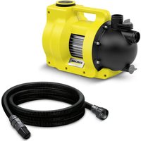
| Product type | Submersible drainage pump |
| Brand | Kärcher |
| Model | SP 5 Dual |
| Use | Private household use |
| Nominal power | 500 W |
| Mains voltage | 230-240 V |
| Mains frequency | 50 Hz |
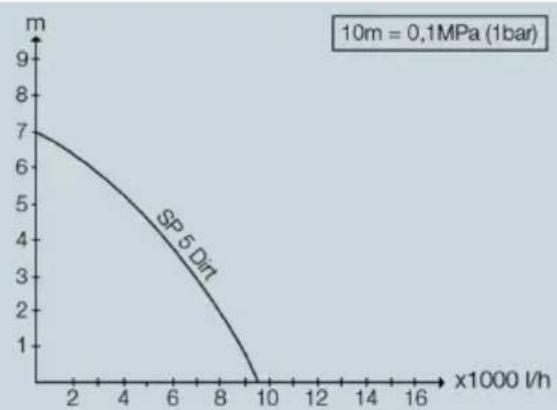
| Max. flow rate | 9500 l/h |
| Max. pressure | 0.7 bar |
| Max. delivery head | 7 m |
| Max. immersion depth | 7 m |
| Max. particle size | 20 mm |
| Weight (without accessories) | 4.8 kg |
| Power cable length | 10 m |
| Air venting device | Automatic |
| Operating mode | Automatic (float switch) / Manual |
| Hose connection | Quick-Connect |
| Filter basket | Adjustable (2 positions) |
| Switching height (auto mode, high position) | 255-310 mm (on), 115-220 mm (off) |
| Residual height (manual mode, transport) | 25 mm |
| Residual height (manual mode, flat suction) | 1 mm |
| Maintenance | No maintenance required |
| Frost protection | Empty the unit completely and store in a frost-free place |
| Warranty | According to country conditions, material/manufacturing defects |
Frequently Asked Questions - SP 5 Dual Kärcher
User questions about SP 5 Dual Kärcher
0 question about this device. Answer the ones you know or ask your own.
Ask a new question about this device
Download the instructions for your Pump in PDF format for free! Find your manual SP 5 Dual - Kärcher and take your electronic device back in hand. On this page are published all the documents necessary for the use of your device. SP 5 Dual by Kärcher.
USER MANUAL SP 5 Dual Kärcher
natural_image
Yellow KARCHER water purifier with black base and hose, no visible text or symbols on device bodyDeutsch 3
English 8
Français 12
Italiano 17
Nederlands 22
Español 27
Português 32
Dansk 37
Norsk 41
Svenska 45
Suomi 50
Ελληνικά 54
Türkçe 59
Русский 63
Magyar 69
Čeština 74
Slovenščina 78
Polski 82
Românește 87
Slovenčina 92
Hrvatski 96
Srpski 101
Български 105
Eesti 110
Latviešu 115
Lietuviškai 119
Українська 124
Қазақша 129
中文 134
138 العريبه
Register and win! www.kaercher.com/register-and-win

001
EAL

59678660 (08/17)
natural_image
Close-up of a mechanical assembly with a yellow component and a black bolt, showing no visible text or symbols.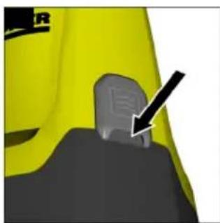
natural_image
Close-up of a yellow and black mechanical component with a gray handle and arrow indicator (no text or symbols)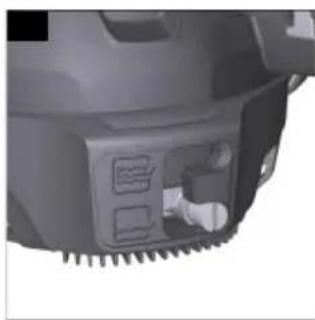
natural_image
Close-up of a mechanical component with serrated edges and a white connector (no visible text or symbols)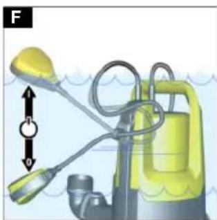
natural_image
Illustration of a yellow underwater spray gun with attached hoses and a valve, showing water flow direction (no text or symbols)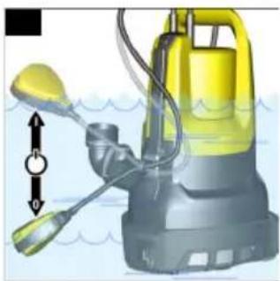
natural_image
Illustration of a yellow and black water purifier with a water valve, showing fluid flow (no text or symbols)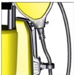
natural_image
Close-up of a yellow fuel pump nozzle with attached tubing (no visible text or symbols)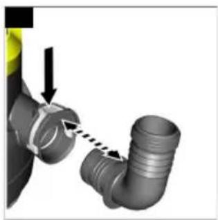
natural_image
Close-up of a pipe fitting with arrows indicating movement or assembly (no text or symbols)Inhalt
Environmental protection ..... 8
Accessories and spare parts ..... 8
Scope of delivery 8
Warranty.... 8
Device description 9
Installation 9
Initial startup....9
Operation 9
Transportation 11
Storage 11
Care and service 11
Troubleshooting guide ..... 11
Technical data 11
General notes

Read these original operating instructions and the enclosed safety instructions before using the device for the first time. Act in accordance with them.
Keep both books for future reference or for future owners.
Intended use
Only use the device in private households. Intended use:
● Removal of water from building sections in the event of flooding
● Transfer and pumping out of water from containers
● Water removal from wells and shafts
- Pumping fresh water out of boats and yachts
For notes on functionality, see chapter Operation
Permissible feed fluids
Permissible feed fluids:
- Fresh water to the specified degree of contamination - for the maximum particle size, see chapter Technical data
- Swimming pool water with intended dosage of additives
- Washing lye
Improper use
Note
The manufacturer accepts no liability for possible damage caused by improper use or incorrect operation.
The device is not suitable for continuous pump operation (e.g. continuous circulation in the pond) or as a fixed installation (e.g. lifting system, fountain pump).
Environmental protection

The packing materials can be recy- cled. Please dispose of packaging in rdance with the environmental regula-

Electrical and electronic appliances contain valuable, recyclable materials and often components such as batter-rechargeable batteries or oil, which - if called or disposed of incorrectly - can be a potential threat to human health and environment. However, these compounds are required for the correct operation the appliance. Appliances marked by this tool are not allowed to be disposed of either with the household rubbish.
Notes on the content materials (REACH)
Current information on content materials can be found at: www.kaercher.de/REACH
Accessories and spare parts
Only use original accessories and original spare parts. They ensure that the appliance will run fault-free and safely.
Information on accessories and spare parts can be found at www.kaercher.com.
Scope of delivery
The scope of delivery for the appliance is shown on the packaging. Check the contents for completeness when unpacking. If any accessories are missing or in the event of any shipping damage, please notify your dealer.
Warranty
The warranty conditions issued by our relevant sales company apply in all countries.
We shall remedy possible malfunctions on your appliance within the warranty period free of cost, provided that a material or
manufacturing defect is the cause. In a warranty case, please contact your dealer (with the purchase receipt) or the next authorised customer service site.
(See overleaf for the address)
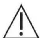
Device description
The maximum amount of equipment is described in these operating instructions. Depending on the model used, there are differences in the scope of delivery (see packaging).
For the figures, please refer to the graphics page
Illustration A
①Carrying handle
②Power supply cable with plug
③Automatic venting device
④ Quick-Connect hose connection
⑤ Pipe unions
⑥Lock for float switch
⑦ Height adjustment for float switch
⑧Float switch
⑨ Setting for filter basket
⑩Filter basket
Installation
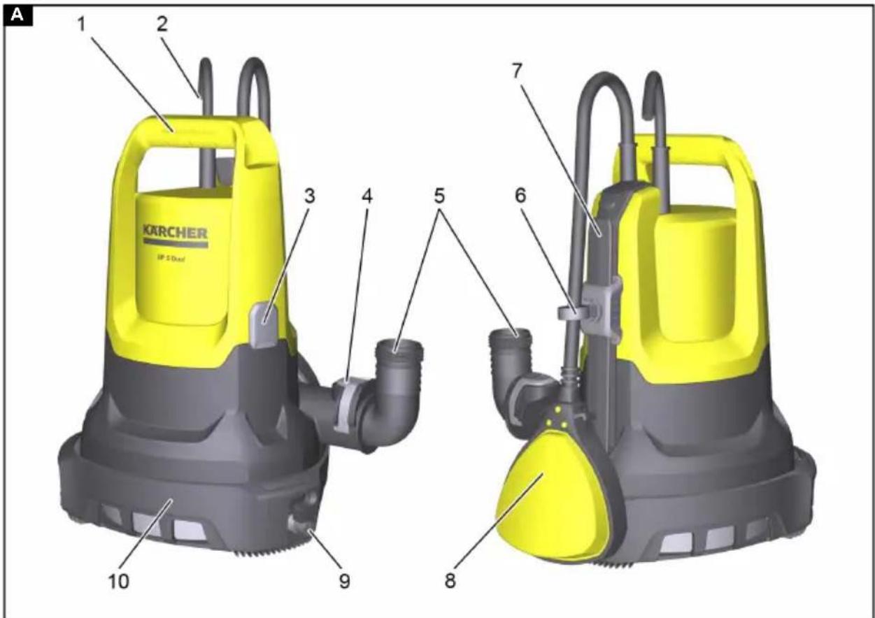
Installing the hose
Note
The pumping capacity is further increased the shorter the hose is and the greater the hose diameter is.
The pipe union is enclosed unmounted with the device.
- Slide the hose clamp onto the hose.
Illustration B
- When using a hose with a diameter of 34 " or 1":
a Screw the pump connecting piece (see chapter Accessories and spare parts) onto the pipe union.
b Shorten the pump connecting piece using the grooves, according to the selected hose diameter.
The flow volume is increased.
c Slide the hose onto the pump connecting piece.
-
When using a hose with a diameter of 114 ", slide the hose onto the pipe union.
-
Fasten the hose on the pipe union using the hose clamp.
Initial startup
△CAUTION
Improper transportation
Risk of injury and damage
Do not carry the pump using the cable or hose.
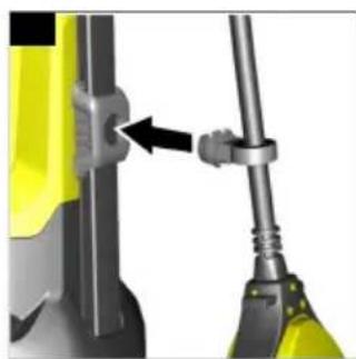
-
Plug the pipe union into Quick-Connect. The hose is connected up.
-
Lock in place the float switch at the height adjustment.
Illustration C
-
Position the pump in the feed fluid:
-
Fasten a rope to the carrying handle and immerse the pump.
-
Set down the pump horizontally on firm ground. If the ground is muddy, use a brick or something similar for stabilising.
-
Ensure that the suction area is not blocked.
Operation
Automatic venting
If the fluid level is low, any sucked-in air, or air present in the pump, may escape via the automatic venting device. Fluid can also leak along with air.
Illustration D
Setting the filter basket
The filter basket can be operated in 2 positions.
Illustration E
 | Waste water and clear water deliveryWe would recommend this filter basket position at the start of the pumping process, since on this occasion the pumping capacity is at its greatest. |
 | Flat vacuumingIn this filter basket position, flat vacuuming is possible up to 1 mm residual fluid height in manual mode. |
-
Put the pump on the ground.
-
Clamp the pump between your feet and take hold of the carrying handle.
- Unlatch the filter basket by turning the handle clockwise.
- Move the filter basket into the required position.
- Lock the filter basket in place by turning the handle anticlockwise.
Automatic mode
In automatic mode, the float switch controls the pumping process automatically.
The pump switches on as soon as the float switch reaches the switch-on height caused by the rising fluid level.
The pump switches off as soon as the float switch reaches the switch-off height caused by the sinking fluid level.
The float switch must be able to move freely.
Note
The switching heights vary depending on:
- Position of the float switch
- Cable length between the float switch and lock.
The cable length must be at least
2.5 cm. We would recommend retaining the set cable length.
For information on the switching heights, see chapter Technical data.
- Set the float switch using the height adjustment, and the cable length between the float switch and the lock.
Note
When the pump is operated unattended, always set the float switch to the uppermost position in order to ensure that the pump can switch off reliably.
Illustration F
When the float switch is set to the lowermost position, set the cable length between the float switch and the lock to 2.5 cm, see marking on the cable.
Illustration G
- Move the filter basket into the "waste water and clear water delivery" position.
- Plug the mains plug into the socket.
Manual operation
In manual operation, the pump stays switched on.
The residual fluid height (see chapter Technical data) can only be reached in manual operation.
ATTENTION
Damaging the pump due to dry running Increased wear and tear
Do not leave the pump unattended in manual operation.
Switch off the pump for dry running.
- Fasten the float switch in the lock, with the nose pointing upwards.
Illustration H
-
Move the filter basket into the required position, depending on the fluid level (for the minimum fluid height and residual fluid height, see chapter Technical data).
-
Plug the mains plug into the socket.
Optimising the flow rate
The flow rate is further increased:
● The lower the delivery height is
● The greater the diameter of the hose used is
● The shorter the hose used is
● The smaller the pressure loss caused by the connected up accessories
Ending operation
-
Remove any dirt from the device.
-
Pump clear water.
-
Rinse out the pump.
-
Press the button for Quick-Connect and remove the pipe union.
Illustration I
The hose is removed.
- Where necessary, remove residue from the hose and on Quick-Connect.
- Pull the mains plug out of the socket.
Transportation
- Carry the device.
- Lift up the device by the carrying handle, and carry it.
- Fasten a rope to the carrying handle, and use the rope to lift up the device - and carry it.
● Transport the device in a vehicle.
- Secure the device against slipping and tipping over.
Storage
ATTENTION
Danger of frost
Incompletely emptied devices can be destroyed by frost.
Completely empty the device and accessories.
Protect the device from frost.
- Completely empty the pump.
- Allow the pump and the hose to dry out.
- Store the pump in a frost-protected place.
Care and service
The device is maintenance-free.
Troubleshooting guide
Malfunctions often have simple causes that you can remedy yourself using the following overview. When in doubt, or in the case of malfunctions not mentioned here, please contact your authorised Customer Service.
The pump is running, but not delivering Air is in the pump.
- Pull the mains plug out of the socket and plug it in again several times, until the fluid is drawn in.
The suction area is clogged.
- Pull the mains plug out of the socket.
- Clean the suction area.
The fluid level is too low in manual operation.
- Immerse the pump deeper into the feed fluid if possible, see chapter.
The pump does not start up, or stops suddenly during operation
The power supply is disconnected.
- Check the fuses and the electrical connections.
The thermal protection switch has switched off the pump because of overheating.
- Pull the mains plug out of the socket.
- Allow the pump to cool down.
-
Remove any dirt particles in the suction area.
-
Clean the suction area.
-
Prevent the pump from running dry. Dirt particles block the suction area.
-
Pull the mains plug out of the socket.
- Clean the suction area.
The pumping capacity decreases
The suction area is clogged.
- Pull the mains plug out of the socket.
- Clean the suction area.
The pumping capacity is too low
The maximum delivery height is exceeded. The hose diameter and the hose length have been selected incorrectly.
- Observe the maximum delivery height, see chapter Technical data.
- When necessary, select a greater hose diameter or a shorter hose length, see chapter Optimising the flow rate.
Quick-Connect cannot be opened or closed
The push-fit system is dirty.
- Remove the clip.
- Clean the clip.
- Install the clip.
The filter basket cannot be moved.
The filter basket is dirty.
- Loosen the latch screws using a screw-driver.
- Remove the filter basket.
- Clean the filter basket.
- Install the filter basket.
Technical data
Electrical connection
| Mains voltage V 230-240 |
| Power frequency Hz 50 |
| Nominal power W 500 |
Performance data of device
| Flow rate (max.) l/h | 9500 |
Particle size (max.) of per-mm 20 missible feed fluids
Automatic mode
| Switch-on height of float switch (locking in uppermost position) | mm 255-310 |
| Switch-off height of float switch (locking in uppermost position) | mm 115-220 |
| Switch-on height of float switch (locking in lowermost position) | mm 155-210 |
| Switch-off height of float switch (locking in lowermost position) | mm 40-120 |
Manual operation
| Minimum fluid height for waste water and clear water delivery | mm 60 |
| Residual fluid height for waste water and clear water delivery | mm 25 |
| Minimum fluid height for flat vacuuming | mm 40 |
| Residual fluid height for flat vacuuming | mm 1 |
Dimensions and weights
| Weight (without accessories) | kg 4.8 |
Power cable
| Cable length m 10 |
| Subject to technical modifications. |
Contenu
Transport non-conforme
Stille inn filterkurven
Optimere transportmengden
natural_image
Icon showing a gear and wrench inside a square frame (no text or symbols)http://www.kaercher.com/dealersearch