
L 240 S - Lamp STEINEL - Free user manual and instructions
Find the device manual for free L 240 S STEINEL in PDF.
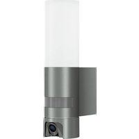
| Product type | LED outdoor wall light with motion detector |
| Brand | Steinel |
| Model | L 240 S |
| Dimensions (W × H × D) | 165 × 305 × 81 mm |
| Supply voltage | 220-240 V, 50/60 Hz |
| Power consumption | 9.3 W |
| Luminous flux | 946 lm |
| Luminous efficacy | 101 lm/W |
| Color temperature | 3000 K (warm white) |
| Color rendering index (CRI) | 82 |
| Average lifespan | >60,000 h (L70B50 at 25 °C) |
| Protection rating | IP44 |
| Protection class | II |
| Impact resistance | IK07 |
| Operating ambient temperature | -20 °C to +50 °C |
| Detection angle | 180° |
| Detector range | max. 10 m |
| Adjustable time delay | 8 s to 35 min |
| Adjustable trigger threshold | 2 to 2000 lx |
| Standby power consumption (detector) | 0.5 W |
| Energy efficiency class of the light source | D |
| Installation | Outdoor wall mounting |
| Detector type | Passive infrared (PIR) |
| Warranty | 3 years |
Frequently Asked Questions - L 240 S STEINEL
User questions about L 240 S STEINEL
0 question about this device. Answer the ones you know or ask your own.
Ask a new question about this device
Download the instructions for your Lamp in PDF format for free! Find your manual L 240 S - STEINEL and take your electronic device back in hand. On this page are published all the documents necessary for the use of your device. L 240 S by STEINEL.
USER MANUAL L 240 S STEINEL
Please read carefully and keep in a safe place.
Under copyright. Reproduction either in whole or in part only with our consent.
-Subject to change in the interest of technical progress.
Symbols

Hazard warning!

Reference to other information in the document.
2. General safety precautions

Disconnect the power supply before attempting any work on the unit.
- During installation, the electric power cable to be connected must not be live. Therefore, switch off the power first and use a voltage tester to make sure the wiring is off-circuit.
- Installing these lights involves work on the mains voltage supply; installation must therefore be carried out professionally in accordance with the applicable national wiring regulations and electrical operating conditions (DE-VDE 0100, AT-ÖVE/ÖNORM E 8001-1, CH-SEV 1000).
- Only use genuine replacement parts.
- Repairs may only be made by specialist workshops.
3. L 240 S / L 220 S L 220
Proper use
- Outdoor light with LEDs as the light source.
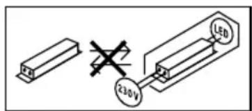
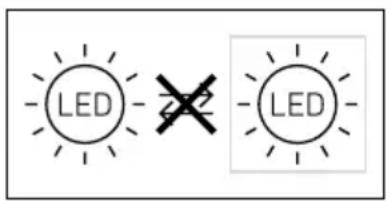
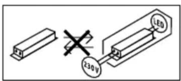
-Suitable for wall mounting outdoors. - The unit is not suitable for connecting to a dimmer.

Not dimmable
-These sensor versions (S versions) also feature an infrared sensor for detecting movement.
Operating principle
-Outdoor lights
-LED technology
The S versions also provide these functions:
- The integrated infrared sensor detects the heat radiated from moving objects (e.g. people, animals).
- The heat detected in this way is converted electronically into a signal that switches the LED light ON automatically.
- The most reliable way of detecting motion is to install the unit with the sensor aimed across the direction in which a person would walk.
-Reach is restricted when the unit is approached head on.
-Obstacles (e.g. trees, walls etc.) interrupt the line of sensor vision.
-Heat radiation is not detected through obstacles (e.g. walls or panes of glass), the sensor is not triggered.
-Sudden fluctuations in temperature as a result of changes in weather are not distinguished from sources of heat.
L 240 S package contents (Fig. 3.1)
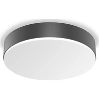
L 220 S package contents (Fig. 3.2)
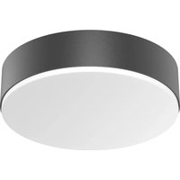
L 220 package contents (Fig. 3.3)
L 240 S product dimensions (Fig. 3.4)
L 220 S product dimensions (Fig. 3.5)
L 220 product dimensions (Fig. 3.6)
L 240 S product components (Fig. 3.7)
L 220 S product components (Fig. 3.8)
L 220 product components (Fig. 3.9)
A Light enclosure with base
B Plug-in terminal
C Wall mount
D Sensor (S only)
Luminous intensity distribution (Fig. 3.10)
4. Installation
- Switch OFF power supply (Fig. 4.1)
The leads consist of three wires:
L = phase conductor (usually black, brown or grey)
N = neutral conductor (usually blue)
PE = protective-earth conductor (green/yellow) If you are in any doubt, identify the conductors using a voltage tester; then disconnect from the power supply again. Connect the phase conductor (L) and neutral conductor (N) to the terminal block.
Important:
Incorrectly wired connections will produce a short circuit later on in the product or your fuse box. In this case, you must identify the individual conductors once again and re-connect them. A mains power switch for turning the unit ON and OFF may of course be installed in the mains supply lead.
Note:
The light source in this light must only replaced by the manufacturer or a service engineer authorised by the manufacturer or by a similarly qualified person.
Connecting the mains power supply lead (Fig. 5.6)
L 240 S, L 220 S wiring diagram (Fig. 4.2)
L 240 S, L 220 S wiring diagram (Fig. 4.3)
5. Mounting
- Check all components for damage.
- Do not use the product if it is damaged.
- Select an appropriate mounting location, giving consideration to sensor reach and mounting height (Fig. 5.1).
Mounting procedure
(Based on the example of L 220)
- Switch OFF power supply (Fig. 4.1).
- Detach light housing from the wall mount, paying attention to the position of the sensor (Fig. 5.2).
Mark drill holes (Fig. 5.3).
- Drill holes and insert wall plugs (concealed power supply cable (Fig. 5.4).
- Drill holes and insert wall plugs (with spacers for surface power supply cable (Fig. 5.5).
- Connect conductors (Fig. 5.6).
- Connect plug-in connectors (Fig. 5.7).
- Fit light enclosure (A) onto wall mount (C). Pay attention to plug-in connections as well as the position of the sensor (Fig. 5.8).
- Screw light enclosure into place (Fig. 5.9).
- Switch ON power supply (Fig. 5.10).
- Make settings (S only) "6. Functions".
6. Functions
The sensor-switched light can be put into service after mounting the light enclosure and connecting to the mains power supply.
Factory settings (S only)
Twilight setting: daylight operation 2000 lux
Time setting: 8 s
Twilight setting / response threshold (S only) (Fig. 6.1)
- The sensor's response threshold can be infinitely varied from 2-2000 lux.
- Control dial set to = daylight operation, approx. 2000 lux.
- Control dial set to = night-time operation, approx. 2 lux.
Time setting (S only) (Fig. 6.1)
Light ON duration can be infinitely varied from 8 s - 35 min
-It is recommended that the shortest time be selected for setting the detection zone.
- Control dial, shortest time = approx. 8 s
- Control dial, longest time = approx. 35 min
Adjusting the detection zone / reach setting (S only)
Depending on the mounting height, the detection zone setting can be optimised to suit requirements. The shroud foil can be used for masking out any number of lens segments to limit reach as required, e.g. to mask out paths or neighbouring property (Fig. 6.2).
-Reach can be adjusted from 2 - 10m by tilting the sensor (D) through 90^ (Fig. 6.3).
House numbers
- Affix the house street number using the stickers provided (Fig. 6.4).
7. Maintenance / care
Warning of hazards from electricity!
Contact between water and live parts can result in an electric shock, burns or death.
- Only clean device in a dry state.
Risk of damage to property!
Using the wrong cleaning product can damage the light.
- Clean device with a moist cloth without detergent.
Important note: the control gear cannot be replaced.

8. Disposal
Electrical and electronic equipment, accessories and packaging must be recycled in an environmentally compatible manner.

Do not dispose of electrical and electronic equipment as domestic waste.
EU countries only:
Under the current European Directive on Waste Electrical and Electronic Equipment and its implementation in national law, electrical and electronic equipment no longer suitable for use must be collected separately and recycled in an environmentally compatible manner.
9. Manufacturer's warranty
This Steinel product has been manufactured with utmost care, tested for proper operation and safety and then subjected to random sample inspection. Steinel guarantees that it is in perfect condition and proper working order. The warranty period is 36 months and starts on the date of sale to the consumer. We will remedy defects caused by material flaws or manufacturing faults. The warranty will be met by repair or replacement of defective parts at our own discretion. The warranty shall not cover damage to wear parts, damage or defects caused by improper treatment or maintenance. Further consequential damage to other objects shall be excluded.
Claims under the warranty will only be accepted if the unit is sent fully assembled and well-packed with a brief description of the fault, a receipt or invoice (date of purchase and dealer's stamp) to the appropriate Service Centre.
Repair service:
If defects occur outside the warranty period or are not covered by the warranty, ask your nearest service station for the possibility of repair.

YEAR
MANUFACTURER'S WARRANTY
| 10. Technical specifications | |
| Dimensions (W×H×D) | L 240 S: 165×305×81 mm L 220 S: 246×251×84 mm L 220: 246×250×57 mm |
| Supply voltage 220 - 240 V, 50 / 60 Hz | |
| Luminous flux/light level L 240 S: 946 lm / 101 lm/W L 220 S: 869 lm / 93 lm/W L 220: 869 lm / 93 lm/W | |
| Power consumption (Pon) L 240 S: 9.3 W L 220 S: 9.3 W L 220: 9.3 W | |
| Sensor on standby (Pst) L 240 S, L 220 S: 0.5 W | |
| Colour temperature 3,000 K (warm white) | |
| Colour rendering index L 240 S: R a = 82 L 220 S: Ra = 83 L 220: Ra = 83 | |
| Average L70B50 at 25°C: >60,000 hours rated life expectancy | |
| Colour consistency SDCM Starting value: 3 | |
| Luminous intensity distribution | |
| Sensor technology (S only) Passive infrared | |
| Angle of coverage (S only) | 180° |
| Detection reach (S only) Max. 10 m | |
| Time setting (S only) | 8 s - 35 min |
| Twilight setting (S only) | 2 - 2,000 lux |
| IP rating | IP44 |
| Protection class | II |
| Impact resistance | IK07 |
| Ambient temperature | -20°C to +50°C |
| Technical documentation at www.steinel.de | |
| These products contain an energy efficiency class "D" light source. | |
11. Troubleshooting
Malfunction Cause Remedy
| Light without power | ■ Fuse faulty, not switched ON, break in wiring | ■ Fit new fuse, turn ON mains switch, check wiring with voltage tester |
| Light not switching ON | ■ Surroundings still too bright (S only) ■ Mains switch OFF ■ Fuse blown ■ Detection zone not correctly adjusted (S only) | ■ Wait until response threshold is reached or adjust setting ■ Switch ON ■ Fit new fuse, check connection if necessary ■ Readjust |
| Light not switching OFF | ■ Continued movement within the detection zone (S only) | ■ Check detection zone and readjust if necessary |
| Light switches ON when it should not | ■ Cars in the street are detected, for example (S only) | ■ Check detection zone and readjust if necessary |
| Changing reach | ■ Differing ambient temperatures (S only) | ■ When it is cold, shorten reach by tilting sensor down, move it up in warm weather |
FR
Piesleguma plans L 240 S, L 220 S (4.2 att.)
Piesleguma plans L 240 S, L 220 S (4.3 att.)
5. Montaža
- Parbaudiet visas detalias, vai tās nav bojatas.
- Bojajumu gadijumā neliotojiet produktu.
- izveliieties montazai piemeroitu vietu, nemot vera sniedzamibu un montazas augstumu (5.1. att.)
Montazas soli
(Uz L 220 piēmērā)
- Atslédziet elektribas apgadi (4.1. att.)
- Atvienojiet gaismekla korpusu no sienes stiprinājumu, pieveršot uzmanibu sensora pozicijai (5.2. att.)
- Atzimejiet urbuma vietas (5.3. att.)
- Izurbiet carumus un ievietojiet dibelus (Zemapmetuma sievads 5.4. att.)
- Izurbiet carumus un ievietojiet dibelus (ar starplikam virsapmetuma pievadam 5.5. att.)
- Pievienojiet pieslēguma kabeli (5.6. att.)
- Pievienojiet savienotajus (5.7. att.)
- Uzspraudiet gaismekla korpusu (A) uz sienas stiprinajuma (C). Pieversiet uzmanibu uzsprazamajiem savienotajiem, ka an sensora pozicijai (5.8. att.)
- Nofiksejiet gaismekka korpusu ar skruvēm (5.9. att.)
- lesledziet stravas padevi (5.10. att.)
Veicietistaniunu(tikaiS) "6.Funkcijas"
6. Funkcijas
Pec tam, kad gaismekla korpuss ir uzmontets un elektrotiklas ir pievienots, sensorgaismekli var sakt lietot.
Rupnicas iestatijumi (tikai S)
Kreslas sensora iestatišana:
dienesgaismas rezims 2000 luksi
Laika iestatishana: 8 s
IOnoJIHHTeJIbHO DeIcTByeT IaBapnAHTOB S:
-BCTpoeHHbI INHpaKpaChbI CEHCOP pernctpnpyet TeNIOBOe N3nyHeHne DBNKyUxxCra O6bekTOB (HaNPIMep, IIOdei, XINBOTbIX N.T.D.).
-TenloBoe n3nyehne npoe6pa3yeTcB 3JIeKTPoHHbI CNHaN, KOTOpbI BbI3bIBaET aBTOMATnueCKOE BKIOUeyHne CBETODNOHOFO CBETNJbHnKa.
-Camay hadekna pernctpaun oecneuBa-ETcMOHTaXOM n3eJIa C6Oky OTHOCHTeJIbHO HapabHeHry DvIXKeHH.
-PaIyC DeIcTBnO rOpAHueH,ecJI Bbl noJxO-dITE HeIOcpeIcTBeHHo K n3deJIInO.
-3arpaKaIauOuIe obBeKtbl (HaIpImep, IpeBbIa, CTeHbI) IpeKePbIBaIOT 3Ohy O6HApUxKeHnCeHCopy.
-B TOM Clyuae, ecn Ha nytn IMeOTc npenrTCTBna (HaNPmep, CTehbl NNI OKOHbIe CTeKna)peNCTpaun TEnNo3JyHeHnePONCXoNT, aCNEIOBaTeNbHO He POn3BONDTCN BKNIOUeHn.
-Pe3Kne IN3MeHEnHr TEMpePaTypbI IN3-3a NO-TOdHbIX BO3DeiCTBn IN3DeJIne He CNOCO6HO OTJNUHTb OT NCTOCHIKOB TEPJa.
O6bEm nocTaBkn L 240 S (pnc.3.1)
Osbem noctabkn L 220 S (pnc.3.2)
06bem nocTbKn L 220 (pnc.3.3)
Pa3MepbIu3dennL240S(pnc.3.4)
Pa3MepeIu3eIeIaL220S(pnc.3.5)
Pa3MepbIu3dEJIyL220(pnc.3.6)
O63op n3denn L 240 S (pnc. 3.7)
O630 np 3denn L 220 S (pnc. 3.8)
O630npn3dennL220(pnc.3.9)
A Kopnyc CBetnIbHnka C waccn
B KoHTaKTHbI 3aXIM
C KpoHHTeH
D CeHcOp (ToJbko S)
PacnpedeeneHne cNJIbI CBeTa (pnc.3.10)
4. MoHTaX
OTKJIouHTb 3JneKtpOnTuHaHe (pnc.4.1)
Cetebo npobod cocton 3 xnl:
L = Φa3a (obbyHNo YepHoro, KopuHHeBOro nn ceporo LBeTa)
N = HjIeBOI npOBIO (HaIe Bcero CINHnI)
PE = npoBOd 3a3eMnIeHnIa (3eIeHbI/KeIeTbI)
B clyae comHeHnIeHTnFIOuPoBaT Ka6JIb C NOMUbIO INDnKaTOpa, 3aTeM CHOBA OTKJIOHTb HAnpXKeHne. PnncOeINHtB pa3HbI (L) n HyJeBOI npOBoN (N) K COOTBETCTByIOUIM KJEMMaM CBETINbHnka.
BaXHo:
HenpaBnIbHOe npncOeHHHe npoBOOB BycTpoNCTBe nIN B paCnpEJIteJIbHOM RaUKe C npedoxpaHntTeJMM MoKET npNBecNT K KOpOTKOMy 3aMbKaHIO. B TAKOM cIyuepe peKomeHnyetc eue pa3 npOBepNTB npoBOJa N 3aHOBO NOkNCHtB nx. Pn Heo6xOIMOCTN B CeTEBoN pOBoD MoKET 6bITB BMOHTnPOBaH BbIKNoUaTeJIb DnA BKIOUeHn I BbIKIOUeHn CTeBOrTOkA.
Yka3aHne:
CBeToN3JyUaTeIb 3TOTO CBeTnJIbHnKa pa3peWaaetcraMeHrTb TOnbKO IPOIN3BOIDTEJIHO,ABTOpN3OBAHHOMY IM cepBnCHOMy TEXHnky JIn JInCy aHaIOrnHoi KBaJIuΦnKaU.
PnpcoeDInHeHne ceTeBOrO npoBoDa (pnc. 5.6)
План подкюецн L 240 S, L 220 S (pnc. 4.2)
План подкюецн L 240 S, L 220 S (pnc. 4.3)
5. MoHTax
- PpOBepuTb BCE KOHCTpyKTHBHeIe DeTaJIHa IpeMET NOBpeXKeHnIa.
- Пи поврахдених He BKliouaTb npOdyKT.
- Bb6paTb NOxOJIeMecTo IJRA MOHTaKa C yHeTOM paIyCa DeIcTBnI M OHTaXHOB BbICoTbl (pnc.5.1)
IopraokMOHTaxa
(на пимеpe L 220)
- OTKJIQUHTb əJneKTpOpiNTaHHe (pnc. 4.1)
OTCOEINHHTB KOPNyc CBETINbHnka OT KPOH- WTeHa, pN 3TOM CJIeINTb 3a NIOJXKeHNiem ceHCopa (pnc.5.2).
- Hametntb OTBepCTnI nIa CBepJeHn (pnc. 5.3).
- PpocBepJIbTb OTBepCTnI N BCTaBtB IIO6eJI (npoBOd cKpbITOn npoBOdkn, pnc. 5.4)
- Порсеверлть OTBERPCTЯ N BCTaBtB ДIOБЕЛ (c pacNOPKAMN B CJlyae OTKpbIToI NOBOdKN, pnc. 5.5)
- PoiKJIIOHTb CoeINHInTeJbHbI Ka6eJIb (pnc. 5.6)
-ПоДКЛЮЧИТБШТЕКЕРпьIE COЕДИЗЕНЯ (pnc.5.7).
- YctaHOBtB KOpNc (A) CBETnIbHnKa Ha KPOH- tTeiH (C). CneITb 3a NOJKeHnEM ITeKePbIX COeINHeHm IN NOJKeHnEM CeHCopa (pnc.5.8).
3aФИКСИРОВАТБ KOPПУС CBETИЛБИКА BИNTAMN (pnc.5.9).
BkIIOuHTb 3JIeKTPoNTaHne (puc.5.10)
- Bылнгь peуларови (Toько S) → "6. 3кпл�арази"
6. 3Kcnpnyatauia
IocJe yCTaHOBKn KOpnyCa CBeTnJIbHnKa N Bbl- NOJIHeHnCeTeBOrO NODKJIouHnN ITOJIoUHbI CEHCOPHbI CBeTnJIbHnK MoXeT 6bITb NyUeH B 3KcPJIyatauIO.
3aBODcKne HacTpoNk (TOJIbKO S)
YcTaHOBKa cyMepeHoro nopora: peKIM dHeBHO OcBeUeHnA 2000 Jk BpemBaKJIoueHnA:8c
YcTaHOBkaCyMepeHOro BKJIIOUeHnIa
(nopor cpa6aTbIbAHn) (Tolbko S) (pnc. 6.1)
-Порог срабастваши ceHCopa moKet 6bITb yCTaHOBJIeH becctypeHyaTO B dnaIa3OHe 2-2000 Jk.
-PeryIaTOp,yCTaHOBneHHbI Ha=peKIM DHeBHOOOCBeUeHn,npM.2000nk.
-PeyIaTOp,yCTaHOBJIeHHbI Ha=peXIM cyMepeHOrOOCBeUeHnIg,OK.2Jk.
Bpem BkIoueHn (TolbKO S) (pnc. 6.1)
-BpemocBeHmMOKeT6bITnIaBHOyCTa-HOBHeHO BnnaHa3OHeOT 8 cek. 10 35 MIn.
-Пи HabcpoIke 3Ohbl OShapyKeHnpeKOMeHdyETcYCTaHOBITb MHNImaJIbHyIO npoJoJXnTeJIbHOCTb.
-MnHmMaJIbHa npoIOnJXnTeJIbHOCTb Ha yCTaHOBOUHOM peYJrTOpe = OK. 8 cek.
- MaKcImaJIbHaI npOIOJIxKITeJIbHOCTb Ha yCTaHOBOUHOM peryJrTope = OK. 35 MInH.
YcTaHOBka 30HbI O6HApXeHnra / perylnpOBKa paAnuCa DeiCTBnra (TOJbKO S)
-B3aBNCIMOCTNOT BbICOTbMOHTaKa npn HeoBXOIMOCTN MOXHO pON3BecTOn OTTMaJIbHyUyCTAHOBky 30HbI O6HApxKeHn. POnycFepnueCKa 3acNoHka npeHa3Haayetc dJa 3acNoHaCErMeHTOB JInH3bl, T.e. dJa yMeHbJHeHn paDnYCa JeICTBnB B KaKdOM OTdEJIbHOM CInyae.HanpImep, YTO6bl BbIeINMb PeWexOxDhie DOpOKKn nn COCeIDCKne UyAcTKn (pnc.6.2).-BlaRaOpAraBepTtKaJIbHOMy DmIXKeHNIO CeHCopa(D) Ha 90^ paDiNyC DeiCTBnM MOxHo peryInpoBaTb ot 2 do 10 M (pnc.6.3).
Homepa DOMOB
HaheCTn HOMepa DOMOB C NOMOUsIO npNlae-MbIX HaKJeeK (pnc.6.4).
7. TexHnueckoe 06cnyxnbAHne/yyxO
IpeynpeXeHne 6 onachocT8x n3-3a yapa 3JIeKTPnueCKm TOKOM!
IOnaHaHe BoBb Ha TOKOpBOJaUe DeTaHIMoKET npIBOHTb K yDapy 3JIeKTpUeCKM TOKOM, OXOrAM INI JTeTAlbHOMY IcxOdy.
- UHCTITb I3dJIe TOnIbKO B CyXOM COCTOHN.
Onachoctb mmyueeCTbeHHoro yuepe6a!
HenpaBnIbHbIe YIcTReIe CpeIcTBA MoYr T NOBpeIITb I3dEJIe.
- YNCTNTb N3dJIne CJIeRka yBnaXHeHHoT TpIkoJ 6e3 YNCTTuaX CpeDCTB.
Baxkho:Pa6ooye n3dJIne 3aMeHnTb HeIb3y.
8. Ytvn3aun
3neKtpnpnbopbl, KOMnJIeKTyUOuIe N yNaKOBky CJeNyET HaPabTb Ha 3KOJIoRnHyIO BTOpNHyIO nepepa60Ky.

He BbIbpaCbIBaTb 3JIeKTpOpnpOpblB 6bITOBbIE OTXoDbI!
TolbkoДЯСТРАн EC:
Corglacno DeiEcTByuOeI EbponeNcKo DNpeKtNBe
No OTPa6oTaHHOMy 3JeKtpnueckOMy N 3JeKtpOHHOMy OOBpyOBAHNIO ee peaIN3aUIM B HauIN-
OHaJIbHbIX 3aKOHOJaTeJIbCTBAX OTPa6oTaHHbIE
3JeKtpoPn6Opbl DOJXHbI CObnpTaBcR OTdJIbHO
HAnpaBJIaTBcRa Ha 3KoJIoTNHyIO BTOpnHyIO
Hepepa6OTKy.
9. Гаши позиюпеля
DaHhoe n3dene npOn3BODCTBa Steinel 6bIIO c OOCobIM BHIMaHnEM n3rOToBJeHO u NCbITaHO Ha pa6oTOcNOC6HOCTb N 6e30NaCHOCTb EKCNyAtauNN COOTBeTCTBeHHO DeiCTByUOuM INHCTpyKcYMa, a NOTOM NOBepHyTO Bb6OpOHMy KOHTpONIO KauecTBA. FInpMa STEINEL rapaHTnpyET BBICOKoe KaueCTBO N HAdExKHyU pa6Ory n3dEJIa. FapantnHbI CPOK 3KcNlyatauN COCTabJrE T 36 MeCraeB CO DnI PPOdaXn I3dEJIa. FInpMa o8yETcY UcTpaHNTb HeOCTaTKN, KOTOpBIE BO3HKnB BCNECTBne DepeKTA MaTePnaJa NII KOHCTpyKcU. DepeKtBu YcTpaHAnOTcnyTEM peMOHTa I3-DeJIa JNo6 3aMeHOH HeCNPpABhIX DeTaN No YCMOTpeHnIO QnPmbl. FapantnHbI CPOK 3KcNlyatauN He pAcNPocTpaHReTcN Ha NOBpeXdEHIa N DepeKtBu, Bo3HKnUe B pe3yNbTaTe I3HOCA DeTaN, HeHaNDexKaUe N 3KcNlyaTaUuN yXoJa. FInpMa He Hecet OTBETCTBeHHOCTN 3a MaTePnaJIbHbI yUePb TpeTbNx LIu, HaHeceHHbI B IpOueCE 3KcNlyaTaUuN I3dEJIa.
IapaHTnI npedocTbJIeTcTOJbKO B TOM Clyuae, ECNI N3dJIeB CObpaHOM N yNaKOBaHHOM BInDE C KpaTKIM ONUcaHMe HEnCnpaBHOCTN 6blO OT- nPaBHeHO BmEcTe C pINIOXKeHHbIM KaCCOBbIM YeKOM NJI KBrTaHcnei (C DaToI npOJaXn I NeaTbIO TOPROBOI npedpNtTn) NO aDpeCy cepBnCHoMactepckOn.
PemOHThbI cepBnC:
No nCTeHn rapaHTnHO rpoKa nn npn HauHn HEnoJaOK, NCKJIooHaOuXrapaHTnIO, ObaPATNTecb B 6JnxKaIWee cepBnCHoe npednpTne, TTObI NOJyHTb INΦOpMaUIO O BO3MOxHOCIn peMOHTa.

PperIeHa ypeLa L 240 S (pnc.3.7)
PperneHa ypea L 220 S (pnc.3.8)
PperneHa ypea L 220 (pnc.3.9)
A Kopnyc Ha Jama c uacn
B Kjema
C CToiKa 3a CTeHa
D Cen30p (cMo S)
Pa3npedeJeneHe Na CBETnHaTa (pnc. 3.10)
4. MoHTax
- Ia ce n3KJIIOHn eIeKtpo3axpaHbAHeTo (pnc. 4.1)
Ka6eJIbT cIbIbPka 3 npOBdHnka:
L = φa3a (obukHOBHe ηepeH, KaΦyB nJIn CNB)
N = Hya (ObukHOBeHO CnH)
PE = 3a3eMBAu, npoBOHnK (3eJIeH/KbIIT)
Pn CbMHeHne, npOBOnHnUte Tpr6Ba da 6bDat NdeHTnCnnpaHc ypeD 3a npOBepKa Ha HApEKeHNeTO, cJeD KOeTO OTHOBO Da 6bDat CBp3aHn, 6e3 HApEKeHne. Fa3aTa (L) n HyNaTa (N) ce CBp3BaT KbM JyCTep KJIeMaTa.
Baxkho:
Pa3mHa Ha npOBOnHnUte BODI DO KbCO CbeiHeHneB Upea nn Ta6IoTO C npEpa3nteI. PnTaKbB CnyaB BCEKN npOBOnHk Tpr6Ba Oue BeHbX Da 6bJe NdeHTnФuipan H NaHOBO CBp3aH. KbM CNCTemata, pa3bnpa ce, MoKe da 6bJe Do6aBeH npeKbCBauch, 3a BKJIIOUbaHe u N3KJIIOUbaHe.
CbeHne:
OcbETHTIHTO TaNo Ha Ta3n IaMna MoKe da 6bDe 3aMeHrHO Camo OT POnI3BOITeJI NII NOpBuaHOT HeO CepBn3eH TexNk NII Dpyr TexNk C NOIObHa KBaINcPknKaUra.
Cbbp3BaHe KbM MpeXkaTa (pnc. 5.6)
Планн ha CBbp3BaHe L 240 S, L 220 S (pnc. 4.2)
Планн ha CBbp3BaHe L 240 S, L 220 S (pnc. 4.3)
5. MoHTax
- Bcnyk n YaCTn Da ce npOBepaT 3a ueTn.
- Пи поврени рpoodyкът да He ce nycka в Ezekлноataць.
-Да ce n36epe IOdXOJaIc MOCTo 3a MOHTaK, cbo6pa3raBaIKce C O6XBaTa N BnCOUnHaTa Ha MOHTaK (pnc.5.1).
PocJeIOBaTeJIHOCT 3a MOHTaX
(no npimepa Ha L 220)
-Да ceи3КЛIOч eJIeKТр03axpaHbAHeTO (pnc.4.1).
- KopnycBT Da ce OTdenn OT cToiKaTa 3a cTeHa, npu ToBa Da ce CNeDn NOnuTnHa CeH3Opa (pnc.5.2).
-Да ce МаркИраТ MecTaTa 3a npOБиВанe (pnc.5.3).
-Да ce npobnT dynknte n da ce noctabrt
нобелte (ckpntu kaebeni pnc.5.4).
-Да ce npo6nT dynknte n da ce noctabrt nIO6nTe (c noIOnKKn npu otKpTu Ka6en pnc.5.5).
- Ka6eInte da ce cbbpxkat (pnc. 5.6).
- KIeMnTe Da ce CBbpxKaT (pnc. 5.7).
- KopnycT Ha JAmnata (A) Da ce NoctaBn Ha CTOnKaTa 3a CTeHa (C). Da ce CJIeJr KJIeMInTe IN NO3NtTa Ha CEH3Opa (Pnc. 5.8).
- Kopnycby Ha JamaNaTa Da ce fukncpa C BnHTObe (pnc. 5.9).
- EneKtpo3axpaHbAHeTo Da Ce BKIOUHy (pnc. 5.10).
- Да се наразов rat Habстpoик (само S) → "6.Функци".
6.Функци
Clek KaTO KOpNycbTe MOHTnpaH N CBbp3BaHeTo KbM MpeKaTa e OcbueeCTBeHO, Ceh3OpHaTaNAMMaMOKe Da 6bIe NcHata B EKcnloaTaun.
3aBODsKn HAcTPOJKn (cMo S)
HaCTpoiKa Ha CBeTIOUoyBCTBNTeJIHOCTTa:
IHeBeH peXIM 2000 lyKca
HaCTpoiKa Ha BpeMeTo: 8 c
Hactpoika Ha CBetIooyBCTBNTeJIHocTtA/ npar Ha 3aIeIcTBaHe (cMo S) (pnc. 6.1)
-Бe3TeENHOrpeYnIpaHeHa npara Ha 3aEnCTBaHe Ha ceH3Opa Mekdy2-2000 lykca.
-PerynataopHa=DHeBHa CBeTmHa, OKoJIO 2000 lyKca.
- PerúnalopHa = cna6a cBeTnHa, okono 2 nykca.
HactpoikKa Ha BpeMeTo (cAmO S) (pnc. 6.1)
-Be3CTeNEHNOperyIINpaHeHaBpeMeTOOT8ceK.-35MNH.
-Прин Настюйка на обхва се пенирьчы д
6ьдпиЗбразнай-Kратугий Иntервал.
- PerjlaTop NaH-KpaTbK INHTepBaI = OKOJI 8 cek.
- PeryanaTop Hau-NbIbI nHTepBaI = OKONO 35 MIn.
HactpoikKa Ha 30HaTa Ha 3acuane / onpeJeHa He 6xbata (cmo S)
- B 3aBNCIMOCT OT BnCOUHaTa Ha MOHTaK IN CNOpeH HeOBxODIMOCTTA, OxbaTbT MoKe Ja 6bJe ONTtMaJIHO peryIIPAH. NOKpNBauTo FOJIno ClyKIN 3a 3akPnBaHe Ha JekAnHg 6poi CeRMENTN OT ObeKTNbA, CbOTBETHO OxbaTa Da 6bJe INDINBnDyALnO ckbceH, HApPmEp 3a Da CE IN3KJIIOuHAT PbTEKn INN CbCedHn NapcEIN (pnc.6.2).
-06xbatbT MoKe Ia 6bIe HAcTePoEH NocpeiCTBOM BepTuKaJIHO HaKJIaHRe Ha CeH3Opa (D)c 90^ MeJy 2-10 M (pnc.6.3).
Homepa Ha Kbusn
- Homepata da ce 3aIenT c npInoxKeHnte JepeHKn (pnc.6.4).
7.Подрьжka/грижа

PpeynpeKdHne 3a onacHOCTn ot en. Tok!
KoHTaKTbT Ha BODa C yactN, IPOBeXdaun TOK, MoKe Da IOBeJe Do eJekTpueeCKn 10K, n3rapHnI NmCmbPT.
- YpeIbT da ce nouchTa caMo cyx.
OnachoCT OT 5eTn!
Pn n3noJ3BaHe Ha nOprpeWeH noOuNCTBaU npenapat ypeT MoKe Da 6bJe NOBpeDeH.
- YpeIbT da ce NouchTba c Jleko BnaJHa KbPna, 6e3 nouchTbaU npenapaT.
Baxho:ypeNbT He MoXe Da 6bJe 3aMeHn.
8. OTeTpaHЯBaHe
EneKtpoypei, npHaJnEJXHocTn I ONaKOBKn Tp6Ba Da 6bDat peuKlnpaHn, C cen Ona3BaHe Ha OKoHaTa Cpea.

He n3XbIpyTe eJekTpoyeDn c o6uNTe domaHn OTnaDbu!
Camo 3a cTpaHn ot EC:
CnpedJeCTBaUaTa DnpeKtNbHa Ha EC 3a cTapn eJektpoHHn EJekTpOpyPeuN TpaHCNoHpaHeTo B HauHOHaHo npaBO, eJekTpOpyPeuN, KOITO NOBue He MoRat Da 6bDat yNtpe6yBaHN, Tp6Ba Da 6bDat pa3dEJIHO Cb6upaHn N peuKlmpaHn, C ceJ Ona3BaHe Ha OKoJHaTa Cpea.
9. rapaHcIy OT npOn3BODnteJIa
To3n npOdyKT Ha Steinel e npOn3BedeH c HauTROJMAO CTapaHne, npOBepen e 3a fynHKUHOHaJIHOCT N 6e3OpaNCHOCt, CnpoE I DeIcTBaUHTe pa3nope6b, CJIeI KOETO e IIOJIOXeH Ha KaueCTBeH KOHTPOJ, Ha npInuHa Ha clyuaHnra n36Op. STEINEL rapaHTnpa nepfekTHa n3pa60TK a fynKUHN. FapAHnTa e c npOdbJxKITeHOCt 36 Meceua n 3aNoyBa OT DeHЯ Ha NOKyPkata. Hne OTCpaHЯBaMe DeFekTN, npUnHHeH ON TpEwKn B npOn3BODCTBOTO INI KaueCTBOTO Ha MaTePnAJa, peMOHTN
paKn nn 3aMeHn KeTHeactn, nHaun36op. IapaHuaTa He Baxn 3a uetn no n3HocBaunCe aactn, KaTOn n 3a uetn n deKeTn, noJyueHn B pe3yntaT Ha HnpaBnHa ynotpeba nn npdpbXk. PocJeBaun uetn Ha ujxnn ppeMetn Ca N3KIOUeHN OT rapaHuaTa.
IapaHnraTa e BaJnHa cAmO, aKO Hepa3rIo6eHNrYpei 6bJe n3npaTeH Ha CbOTBeTHncaepBn3,do6pe oNaKOBaH nPnPdpyKeH OT KpaTKo OnncAHe Na DeFeKeTa, Kacoba BeIexKa uNn paKtypa (DaTa HnOKyPkA u Nechat Ha TbproBeu).
PemOHTeH cepBn3:
Cnei n3TuHaHe Ha rapaHcnaTa IIn npn DepeKtn, HeNOKpNTn OT rapaHcnaTa, NOnNTaIe B Hau-6n3Kn 3aBOdCKn CepBn3 3a Bb3MOxHocTnTe 3a peMOHT.

TOJINH TAPAHUNAOT PON3BOIDTEI
10. TexHnueckn daHHN
| Размери (Ш × В × Д) | L 240 S: 165×305×81 MM L 220 S: 246×251×84 MM L 220: 246×250×57 MM | |
| Зхранвае 220-240 V, 50/60 Hz | ||
| Сbeltлиен поtok/ocbeteноct L 240 S: 946 lm / 101 lm/W L 220 S: 869 lm / 93 lm/W L 220: 869 lm / 93 lm/W | ||
| Консуmpupa на мошноct (Pon) L 240 S: 9,3 W L 220 S: 9,3 W L 220: 9,3 W | ||
| Standby сенистор (Psb) L 240 S, L 220 S: 0,5 W | ||
| Temperatura на с在里面 3.000 K (тогlio бало) | ||
| Индеса на с在里面 оторожения L 240 S: R a = 82 L 220 S: Ra = 83 L 220: Ra = 83 | ||
| Среда | L70В50 поц 25°C: >60.000 чаа | |
| Проблjetпелност на лимьOT | 3 | |
| Конс stretenция на с在里面 SDCM Начална стойост: 3 | ||
| Раз畴ения на с在里面 SDCM Hachална стойост: 3 | ||
| Сенистор на с在里面 (само S) Пасовен的人生格а ведима сенистор | ||
| Бъл на засUALе: (само S) | 180° | |
| Оxbат (само S) | Мakc. 10 M | |
| Насто只得 на врет氧о (само S) | 8 c - 35 мин | |
| Насто只得 на с在里面 уочьвостrelноста (само S) | 2-2 000 лукca | |
| Вид зашита IP 44 | ||
| Клас зашита | II | |
| Удироч_STОДСВОСТ | IK 07 | |
| Околна Temperatura | -20 дo +50 °C | |
| Тениская дokumenteшия на щадес webw.steinel.de | ||
| Тениская дokumenteшия на щадес webw.steinel.de | ||
| ПюбLEM Рочина Рецниоe | ||
| Лампа се и пожжени | ■ Деске тен пождзител, не в BKлочен, пожь сат кабел | ■ Нов пождзител, за се BKлочи; пожвodництей по се пожергет с урета з пожжени |
| Лампа се в BKлоча | ■ Околнatable среа в ТьрдсCBETпа (само S) | ■ Изчakiные дokато се достагнения прау на заимсяствашили пожрмі райtenов СВКлочаи |
| ■ Пожьсвачт e在其клочen | ■ Нов пождзител,[eveHTyajno ] da se пожерп врьзката | |
| ■ Пождзител деске ■Образът не в是有тошен цelines (cam0 S) | ■ Да се ругулар oTHOBO | |
| Лампа се и злоча | ■Проблжавазо дожжени в обхвatable (само S) | ■ Дa se пожерп обхвatable и[eveHTuajno ] da se ругулар OTHOBO |
| Лампа се в BKлоча пожьвално | ■Засиане нар. на abTomоблі na пьъ (само S) | ■Дa se пожерп обхвatable и[eveHTuajno ] da se ругулар OTHOBO |
| Пожma на hab obxвatable | ■Рazлоча okolna Tempepatура (cam0 S) | ■В студану врeme обхват cMbCS cБС CBALЯну на сEHЗор, hab toplno da се вдигнene |
CN
1. 关于本文件
请仔细阅读并妥善保管!

- Please read carefully and keep in a safe place.
- Symbols
- General safety precautions
- Disconnect the power supply before attempting any work on the unit.
- L 240 S / L 220 S L 220
- Proper use
- Not dimmable
- Operating principle
- Installation
- Important:
- Note:
- Mounting
- Mounting procedure
- Functions
- Factory settings (S only)
- Twilight setting / response threshold (S only) (Fig. 6.1)
- Time setting (S only) (Fig. 6.1)
- Adjusting the detection zone / reach setting (S only)
- House numbers
- Maintenance / care
- Warning of hazards from electricity!
- Risk of damage to property!
- Disposal
- EU countries only:
- Manufacturer's warranty
- Repair service:
- Troubleshooting
- Malfunction Cause Remedy
- FR
- Montaža
- Montazas soli
- Funkcijas
- Rupnicas iestatijumi (tikai S)
- MoHTaX
- BaXHo:
- Yka3aHne:
- MoHTax
- IopraokMOHTaxa
- 3Kcnpnyatauia
- 3aBODcKne HacTpoNk (TOJIbKO S)
- YcTaHOBkaCyMepeHOro BKJIIOUeHnIa
- Bpem BkIoueHn (TolbKO S) (pnc. 6.1)
- YcTaHOBka 30HbI O6HApXeHnra / perylnpOBKa paAnuCa DeiCTBnra (TOJbKO S)
- Homepa DOMOB
- TexHnueckoe 06cnyxnbAHne/yyxO
- IpeynpeXeHne 6 onachocT8x n3-3a yapa 3JIeKTPnueCKm TOKOM!
- Onachoctb mmyueeCTbeHHoro yuepe6a!
- Ytvn3aun
- TolbkoДЯСТРАн EC:
- Гаши позиюпеля
- PemOHThbI cepBnC:
- Baxkho:
- CbeHne:
- PocJeIOBaTeJIHOCT 3a MOHTaX
- 6.Функци
- 3aBODsKn HAcTPOJKn (cMo S)
- Hactpoika Ha CBetIooyBCTBNTeJIHocTtA/ npar Ha 3aIeIcTBaHe (cMo S) (pnc. 6.1)
- HactpoikKa Ha BpeMeTo (cAmO S) (pnc. 6.1)
- HactpoikKa Ha 30HaTa Ha 3acuane / onpeJeHa He 6xbata (cmo S)
- Homepa Ha Kbusn
- 7.Подрьжka/грижа
- PpeynpeKdHne 3a onacHOCTn ot en. Tok!
- OnachoCT OT 5eTn!
- OTeTpaHЯBaHe
- Camo 3a cTpaHn ot EC:
- rapaHcIy OT npOn3BODnteJIa
- PemOHTeH cepBn3:
- TexHnueckn daHHN
- CN
- 关于本文件
- 请仔细阅读并妥善保管!
Brand : STEINEL
Model : L 240 S
Category : Lamp