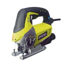
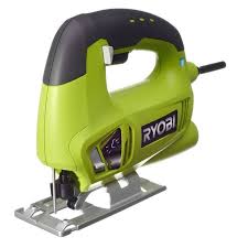
CJS-180L - Jigsaw RYOBI - Free user manual and instructions
Find the device manual for free CJS-180L RYOBI in PDF.
User questions about CJS-180L RYOBI
0 question about this device. Answer the ones you know or ask your own.
Ask a new question about this device
Download the instructions for your Jigsaw in PDF format for free! Find your manual CJS-180L - RYOBI and take your electronic device back in hand. On this page are published all the documents necessary for the use of your device. CJS-180L by RYOBI.
USER MANUAL CJS-180L RYOBI
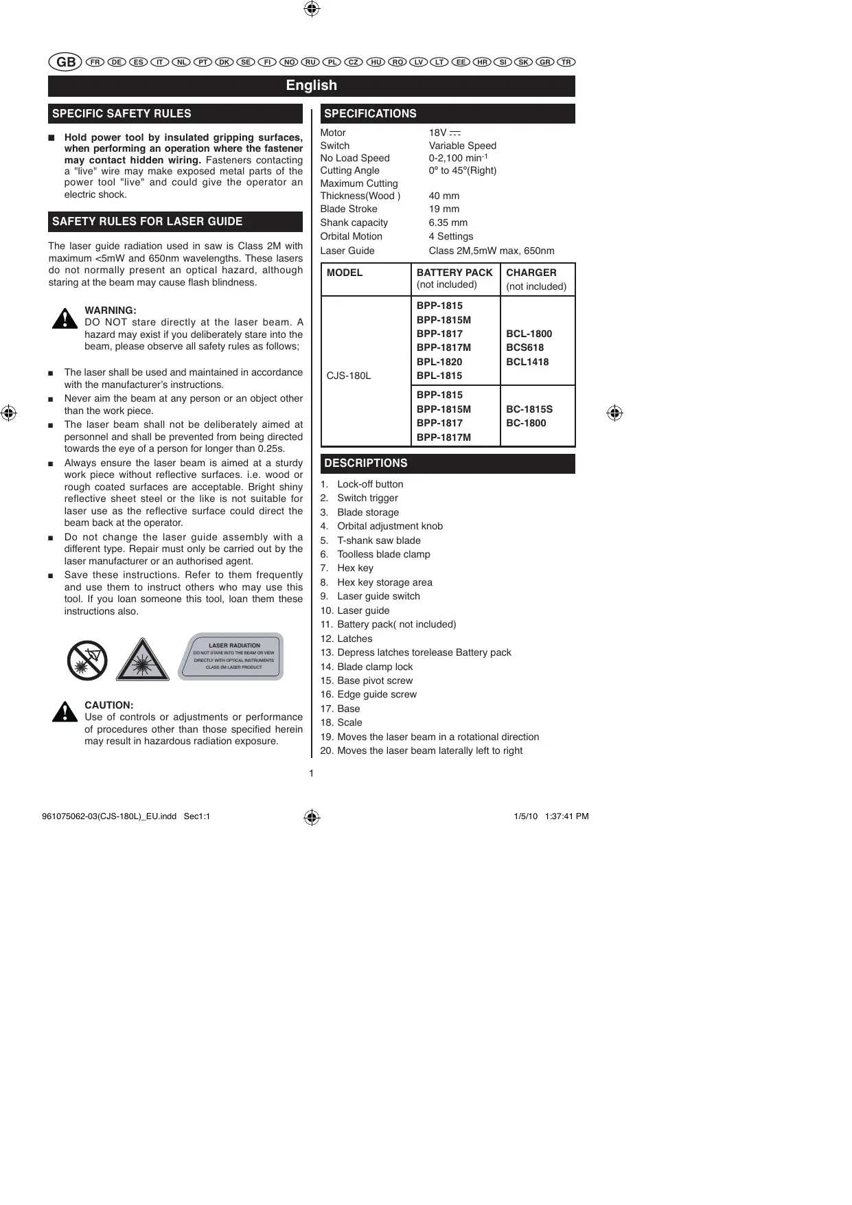
Hold power tool by insulated gripping surfaces, when performing an operation where the fastener may contact hidden wiring. Fasteners contacting a "live" wire may make exposed metal parts of the power tool "live" and could give the operator an electric shock.
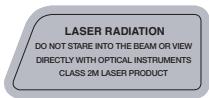
SAFETY RULES FOR LASER GUIDE
The laser guide radiation used in saw is Class 2M with maximum <5mW and 650nm wavelengths. These lasers do not normally present an optical hazard, although staring at the beam may cause flash blindness.

WARNING:
DO NOT stare directly at the laser beam. A hazard may exist if you deliberately stare into the beam, please observe all safety rules as follows;
The laser shall be used and maintained in accordance with the manufacturer's instructions.
- Never aim the beam at any person or an object other than the work piece.
The laser beam shall not be deliberately aimed at personnel and shall be prevented from being directed towards the eye of a person for longer than 0.25s.
Always ensure the laser beam is aimed at a sturdy work piece without reflective surfaces. i.e. wood or rough coated surfaces are acceptable. Bright shiny reflective sheet steel or the like is not suitable for laser use as the reflective surface could direct the beam back at the operator.
- Do not change the laser guide assembly with a different type. Repair must only be carried out by the laser manufacturer or an authorised agent.
- Save these instructions. Refer to them frequently and use them to instruct others who may use this tool. If you loan someone this tool, loan them these instructions also.


CAUTION:
Use of controls or adjustments or performance of procedures other than those specified herein may result in hazardous radiation exposure.
SPECIFICATIONS
Motor 18V---
Switch Variable Speed
No Load Speed 0-2,100 min-1
Cutting Angle 0^ to 45^ (Right)
Maximum Cutting
Thickness(Wood) 40 mm
Blade Stroke 19 mm
Shank capacity 6.35 mm
Orbital Motion 4 Settings
Laser Guide Class 2M,5mW max,650nm
| MODEL | BATTERY PACK (not included) | CHARGER (not included) |
| CJS-180L | BPP-1815 | BCL-1800 |
| BPP-1815M | ||
| BPP-1817 | ||
| BPP-1817M | BCS618 | |
| BPL-1820 | BCL1418 | |
| BPL-1815 | ||
| BPP-1815 | BC-1815S | |
| BPP-1815M | ||
| BPP-1817 | BC-1800 | |
| BPP-1817M |
DESCRIPTIONS
- Lock-off button
- Switch trigger
- Blade storage
- Orbital adjustment knob
- T-shank saw blade
- Toolless blade clamp
- Hex key
- Hex key storage area
- Laser guide switch
- Laser guide
- Battery pack (not included)
- Latches
- Depress latches torelease Battery pack
- Blade clamp lock
- Base pivot screw
- Edge guide screw
- Base
- Scale
- Moves the laser beam in a rotational direction
- Moves the laser beam laterally left to right
English
OPERATION

WARNING:
Do not allow familiarity with tools to make you careless. Remember that a careless fraction of a second insufficient to inflict serious injury.

WARNING:
Always wear safety goggles or safety glasses with side shields when operating tools. Failure to do so could result in objects being thrown into your eyes, resulting impossible serious injury.

WARNING:
Do not use any attachments or accessories not recommended by the manufacturer of this tool. The use of attachments or accessories not recommended can result in serious personal injury.
APPLICATIONS
You may use this tool for the purposes listed below:
Cutting wood surfaces
Cutting thin sheet metal
Cutting plastics and laminates
TO INSERT BATTERY PACK(NOT INCLUDED) Fig.2
Lock the switch trigger by releasing it all the way.
Place the battery pack on the tool.
Make sure the latches on each side of the battery pack snap into place and the battery pack is secured on the tool before beginning operation.

CAUTION:
When placing battery pack in the tool, be sure raised rib on battery pack aligns with the grooves in the saw and latches into place properly. Improper installation of the battery pack can cause damage to internal -components.
TO REMOVE BATTERY PACK(NOT INCLUDED) Fig.2
Lock the switch trigger by releasing it all the way.
Depress the latches on the side of battery pack.
Remove the battery pack from the tool.
BATTERY PROTECTION FEATURES
Ryobi 18 V lithium-ion batteries are designed with
features that protect the lithium-ion cells and maximize battery life. Under some operating conditions, these built-in features may cause the battery and the tool it is powering to act differently from nickel-cadmium batteries.
During some applications, the battery electronics may signal the battery to shut down, and cause the tool to stop running. To reset the battery and tool, release the trigger and resume normal operation.
NOTE: To prevent further shut down of the battery, avoid forcing the tool.
If releasing the trigger does not reset the battery and tool, the battery pack is depleted. If depleted, the battery pack will begin charging when placed on the lithium-ion charger.
BLADE STORAGE(Fig.3)
The blade storage compartment is located on the back of the saw. It is convenient for storing extra blades and storing blades when not in use.
To open: Push the door down with your thumb or finger. Place blades in blade storage compartment.
To close: Push the door up with your thumb or finger.

WARNING:
Battery tools are always in operating condition. Therefore, switch should always be locked when not in use or carrying at your side.
LASER GUIDE(Fig.4)
Depress the laser guide switch to generate a red laser beam on the work surface in front of the saw. Use the laser to guide the saw along the line of cut.
The lock-off button is located on the handle above the switch trigger. You must depress the lock-off button in order to pull the switch trigger. The lock resets each time the trigger is released.
NOTE: You can depress the lock-off button from either the left or right side.
SWITCH TRIGGER(Fig.4)
To turn the saw ON, depress and hold lock-off button, then depress the switch trigger. To turn it OFF, release the switch trigger.
English
OPERATION

WARNING:
This tool is designed to work with T-shank blades. Use with non-T-shank blades may result in blades coming loose from tool, resulting in personal injury or property damage.
BLADE SELECTION
To obtain the best performance from the saw, it is important to select a specific blade for the particular application and type of material you wish to cut. By doing this you will get a smoother, faster cut and prolong blade life.
NOTE: This tool is designed to work with T-shank blades. Other types of saw blades are not guaranteed to work properly and may come loose from the tool.
INSTALLING BLADES(Fig.5)
Remove battery pack.
- Lift blade clamp lock located on front of saw.
Insert saw blade between blade clamp and saw bar.
- Close blade clamp lock.
Replace battery pack.
GENERAL CUTTING(Fig.6)
Rest the front of the saw base on the workpiece and align cutting edge of the blade with the line on your workpiece. Start the saw and move it forward on the work surface. Apply downward pressure to keep the saw steady and only enough forward pressure to keep the blade cutting. Do not force the saw. Forcing the saw may overheat the motor and break saw blades. Broken saw blades must be replaced with new saw blades.
ORBITAL MOTION(Fig.6)
The blade of the saw cuts in orbital motion. This feature is adjustable and provides faster, more efficient cutting. With orbital motion, the blade cuts through your work in the upstroke but does not drag across your work in the downstroke. The higher settings should be used when fast cutting in soft material is desired. The lower settings should be used when cutting materials with more resistance.
STRAIGHT CUTTING(Fig.6)
A straight cut can be made by clamping a piece of wood or straightedge to the workpiece and guiding the edge of the saw against it. Make the cut from one direction only;
don't cut halfway and complete the cut from the opposite end.
SPLINTER-FREE CUTTING(Fig.7)
The base of the jig saw has a narrow slot to permit splinter-free cutting. It is especially useful when cutting plywood. This feature should only be used when making straight cuts or circle cuts. It is not for bevel cutting or plunge cutting.
NOTE: The non-orbital setting also helps reduce splintering when cutting plywood.
positioning the base in the splinter-free cutting position
Remove battery pack
Using the 3mm .hex key provided, loosen base pivot screws and slide base forward.
Always set the cutting angle at 0^ for splinter-free cutting. To set cutting angle at 0^ , align the 0^ mark on the scale with the edge of the motor housing.
NOTE: When setting angle at 0^ for splinter-free cutting, the positive stop notches on the rear of the base are not used.
- Tighten base pivot screws securely.
Remove hex key and return it to the storage area.
Replace battery pack.
OPTIONAL EDGE GUIDE(Fig.8)
An optional edge guide is available for use with the saw. It can be used for making crosscuts and rip cuts.
Remove battery pack.
Insert the arm through the two slots in the base of the saw as shown.
- Adjust edge guide to the desired width and lock in place with the edge guide screw.
Replace battery pack.
SCROLL CUTTING(Fig.9)
Scroll cuts can be made with the jig saw by guiding the direction of the cut with applied pressure on the handle as shown.

WARNING:
Excessive side pressure to the blade could result in broken blades or damage to the material being cut.
English
OPERATION
ANGLE CUTTING (Bevel Cutting) (Fig.10-Fig.11)
Bevel cutting angles may be adjusted from 0^ to 45^ right or left. Angles for cuts from 0^ to 45^ in 15^ increments are marked on a scale on both the left and right side of the base. Notches on the rear of the base provide positive stops at each of the above mentioned 15^ increments. A protractor is recommended when accurate cuts are required.
Remove battery pack.
Using the 3mm hex key provided, loosen the base pivot screws until the base can be moved.
- Slide base backward until base pivot screws can move freely in slots in base.
Align the mark, on the base, of the desired angle with the edge of the motor housing.
Once the desired angle is reached, slide base forward until tab on motor housing aligns with the appropriate notch on rear of base.
NOTE: When making a set-up for accurate cuts with a protractor, or for angles other than the preset 15^ increments, the positive stop notches on the rear of the base are not used.
- Tighten the base pivot screws securely.
- Return hex key to storage compartment.
Replace battery pack.
NOTE: The wide slot in the base must be used when making bevel cuts, scroll cuts, plunge cuts, and when cutting metal.
PLUNGE CUTTING(Fig.12)

WARNING:
To avoid loss of control, broken blades, or damage to the material being cut, always use extreme caution when making plunge cuts. We do not recommend plunge cutting on materials other than wood.
Mark the line of cut clearly on the workpiece.
Set the cutting angle at 0^
Tilt the saw forward so that it rests on the front edge of the base and blade will not come in contact with the workpiece when the saw is turned on.
Make sure the blade is inside the area to be cut.
Using high speed, start the saw and slowly lower the blade into the workpiece until the blade cuts through the wood.
- Continue lowering the blade into the workpiece until the base rests flat on the work surface, then move the saw forward to complete the opening.

WARNING:
Use of controls or adjustments or performance of procedures other than those specified herein could result in hazardous radiation exposure.
ADJUSTING THE LASER(Fig.13)
The laser can be realigned by adjusting the two screws located in the front of the saw. The top screw moves the laser beam laterally from left to right. The bottom screw moves the laser beam in a rotational direction.
NOTE: Draw a pencil line on scrap workpiece parallel to the long edge of the base as a straight line guide to aid in the adjusting process.
Remove the blade from the saw.
Turn laser on.
Rest base of saw on scrap workpiece.
Adjust screws as necessary.
Since blade thicknesses vary, always make a trial cut in scrap workpiece to ensure an accurate cut.
Check for proper alignment.
Repeat as necessary until laser is aligned.
MAINTENANCE

WARNING:
When servicing, use only identical replacement parts. Use of any other parts may create a hazard or cause product damage.

WARNING:
Always wear safety goggles or safety glasses with side shields during power tool operation or when blowing dust. If operation is dusty, also wear a dust mask.

WARNING:
To avoid serious personal injury, always remove the battery pack from the tool when cleaning or performing any maintenance.
GENERAL MAINTENANCE
Avoid using solvents when cleaning plastic parts. Most plastics are susceptible to damage from various types of commercial solvents and may be damaged by their use. Use clean cloths to remove dirt, dust, oil, grease, etc.
English
MAINTENANCE

WARNING:
Do not at any time let brake fluids, gasoline, petroleum-based products, penetrating oils, etc., come in contact with plastic parts. Chemicals can damage, weaken or destroy plastic which may result in serious personal injury.
Only the parts shown on the parts list are intended to be repaired or replaced by the customer. All other parts should be replaced at an Authorized Service Center.
ENVIRONMENTAL PROTECTION
Recycle raw materials instead of disposing as waste. The machine, accessories and packaging should be sorted for environmental-friendly recycling.
SYMBOL

Safety Alert
V
Volts
min-1
Revolutions or reciprocations per minute
一
Direct current

CE Conformity

Please read the instructions carefully before starting the machine.

Recycle unwanted
Waste electrical products should not be disposed of with household waste. Please recycle where facilities exist. Check with your Local Authority or retailer for recycling advice.

Français
CONSIGNES DE SECURITE SPECIFIQUES AUX SCIES SAUTEUSES
| MODELE | BATTERIE (non fournie) | CHARGEUR (non fournie) |
| CJS-180L | BPP-1815 | BCL-1800 |
| BPP-1815M | ||
| BPP-1817 | ||
| BPP-1817M | BCS618 | |
| BPL-1820 | BCL1418 | |
| BPL-1815 | ||
| BPP-1815 | BC-1815S | |
| BPP-1815M | ||
| BPP-1817 | BC-1800 | |
| BPP-1817M |
DESCRIPTION

m = 311
LASERPRODUKT DER KLASSE 2M

VORSICHT
| MODELO | BATERÍA (no suministrada) | CARGADOR (no suministrado) |
| CJS-180L | BPP-1815 | |
| BPP-1815M | BCL-1800 | |
| BPP-1817 | BCS618 | |
| BPP-1817M | BCL1418 | |
| BPL-1820 | ||
| BPL-1815 | ||
| BPP-1815 | ||
| BPP-1815M | BC-1815S | |
| BPP-1817 | BC-1800 | |
| BPP-1817M |
DESCRIPICón
| MODELLO | BATTERIA (non fornita) | CARICABATTERIA (non fornito) |
| CJS-180L | BPP-1815 | BCL-1800 |
| BPP-1815M | ||
| BPP-1817 | ||
| BPP-1817M | BCS618 | |
| BPL-1820 | BCL1418 | |
| BPL-1815 | ||
| BPP-1815 | BC-1815S | |
| BPP-1815M | ||
| BPP-1817 | BC-1800 | |
| BPP-1817M |
DESCRIZIONE
Se先进技术 are used to improve the performance of the battery. For example, the battery is equipped with a high-capacity battery and a low-voltage battery. The battery is also equipped with a high-capacity battery and a low-voltage battery.
RIPONIMENTO DELLE LAME (Fig. 3)
ACCUBEVEILIGINGSSYSTEEM (lithium-ion accu)
ZAAGJES OPBERGEN (afb. 3)
ZAAGJES MONTEREN (afb. 5)
RECHT ZAGEN (afb. 6)
SPLINTERVRIJ ZAGEN (afb. 7)
(OPTIONELE) PARALLELGELEIDER (afb. 8)
SCHUINZAGEN (afb. 10 - 11)
STEEKZAGEN (afb. 12)

WAARSCHUWING

m = 311 ;
| MODEL | BATTERI (ikke medleveret) | OPLADER (ikke medleveret) |
| CJS-180L | BPP-1815 | |
| BPP-1815M | ||
| BPP-1817 | BCL-1800 | |
| BPP-1817M | BCS618 | |
| BPL-1820 | BCL1418 | |
| BPL-1815 | ||
| BPP-1815 | ||
| BPP-1815M | BC-1815S | |
| BPP-1817 | BC-1800 | |
| BPP-1817M |
BESKRIVELSE
Drug化进程 - Drug development - Drug development - Drug development - Drug development - Drug development - Drug development - Drug development - Drug development - Drug development - Drug development - Drug development - Drug development - Drug development - Drug development - Drug development - Drug development - Drug development - Drug development - Drug development - Drug development - Drug development - Drug development - Drug development - Drug development - Drug development - Drug
Dansk
VEDLIGEHOLDELS

ADVARSEL
| MODELL | BATTERI (ekstrautstyr) | LADER (ekstrautstyr) |
| CJS-180L | BPP-1815 | |
| BPP-1815M | BCL-1800 | |
| BPP-1817 | ||
| BPP-1817M | BCS618 | |
| BPL-1820 | BCL1418 | |
| BPL-1815 | ||
| BPP-1815 | ||
| BPP-1815M | BC-1815S | |
| BPP-1817 | BC-1800 | |
| BPP-1817M |
BESKRIVELSE
TEXHINUeCKHEXAPAKTEPHCTUKN
Motop 18B---
Kypok PeryJIaTOp ckopocTH
CkopocTb Ha XOIOCTOM XOJy 0-2100 npoxoOB
B MHHTY
YroJI pe3KN 0°-45°
(BIIpaBO/BJIeBO)
MaKcImaJIbHaIgJIy6HNape3KN(IepeBO)40MM
XoIIOJIOTHa 19MM
MOHOCbBaJa 6,35 MM
MaHTHKObI XoJ 4IOLOKeHHa
JIa3epHbI MeTcHKJIacc 2M,5MBr
MAKC.,650HM
| MOДЕЛь | AKKУМУЛЯТОР (BHE KOMПЛЕКТа) | Зaporщные Усторическая (BHE KOMПЛЕКТa) |
| CJS-180L | BPP-1815 | |
| BPP-1815M | BCL-1800 | |
| BPP-1817 | BCS618 | |
| BPP-1817M | BCL1418 | |
| BPL-1820 | ||
| BPL-1815 | ||
| BPP-1815 | ||
| BPP-1815M | BC-1815S | |
| BPP-1817 | BC-1800 | |
| BPP-1817M |
ONHCAHNE
- KhoIIka pa36JIOKpOBKN KypKa
- Kypok
- OTdJIeHHe IINI POJIoTeH
- PerjyIaTOp MaarTHNKOBOrO xOJa
5.ПJOIOTHO JIO63HkC XBOCTOBHKOM T
6.ПаТрОн ПIOЛOTHа CьICTpbIMКрпЛJEHHEM
7.ⅢeTnIgpaHbHKnIOH - MecTo IIA IIeCTHpAHHOKJIIOVA
- BbIKJIHOaTeJIb JIA3epHOrO MeTINKa
10.JIa3epHbIM MeTtHK - AkkymyTOp (BHe KOMIIeKTa)
12.3actekkn - UTo6bI cHrTb aKKMyJITop, HaKMHTe Ha 3aCteKKN
- Pbyiag KpeIIJIeHnI IOJIoTHa
- BnHTbI IOJ IOJOIOBBOI
- BnHT haipablaHOJIe IPOJOJIbHOJ pe3KN
17.ПоJOшВа - JINHeIka
- BnHT KpyroBoI peryJInpOBKn Ja3epHoro MeTUnKa
20.BnHT6OKOBIO (npabo-1eBO)peyIINPbOKNIa3epHOro MeTnuKIA
Pysckn
PABOTA

IPEUYIPEXJEHNE
OBlaIaEB INHCTpyMeHTOM, He terIte 6JInteJIbHOCTN. IOMHHTe, YTO IOCTaTOHc eKyHbI HeBHHMaHnI, YTO6bIIOJYHT BTKeJYIO TpABMy.

IPEUYIPEXJEHNE
IIpn pa6oTe HnCtpyMeHTOM BceIa IOJIb3yIITecb 3aIITHbIMN OvKAMN C O6OKBbIMN IPOTEKTOpAMN. IIpn Hec6oJIHOJeHHN 3TOrO IpaBHLa TexHNKb 6e30JIaNacOcTH NocSTOPOHHe IpeJMeTb MOryt IIOJaTB rIJa3a N bI3BaTb TjKeJIbIe IJa3HbIe TpaBMbl.

IPEUYIPEXJEHNE
NoIb3yItecbToIbKO peKOMeHIOBaHHbIMn H3rOTOBHTeJIeM NtAJIaMn H akCEccyapamH. HcNIObOBAHHepyrHnTeJAEHn H akCEccyapOBBeJET K TjEJIbM TpABMaM.
ПРIMHEHEN
IIPIMUEAHHE: YTObIaKKUMyJIaTOp He OCTaHAbJIHbJIcA, He fOpCnHyTe HnCTpyMeHT.
Ecln nocIe toro, KaK kypok OTnyuIeH, aKKymyJIaTOp H hNCTpymENT He BKJIOuaOTcY ChOBA, 3NaUHT, aKKymyJIaTOp HOJIOcTOBaPraJKeH. YTo6bI 3apAINb t aKKymyJIaTOp, yctAHOBITE eRo B3apAINHOe yCTpoCTBO IJI JInTH-NOHBIX aKKymyJIaTOpB.
OTJEJEHNEIJIHOJOTEH(Pnc.3)
OTJeJIeHneIJIIOJIOTeH HaxOJITcB 3aJIHeJyactH JIo63HaKa. B HEM MoKHO XpaHHTb 3aJaCHbIe IIOJToHa.
TTO6bIOTKpbITbOTJeJIeHHe:HaJKMHTeIIaJIbIeMHa KpbIHKy.YIOJKTNEIOJOITHA BOTJeJIeHHe.
TTo6b3aKpbItbOTJeIeHHe:HaJMMTe IaJIbIeM Ha KpbIIKy.

IPEUYIPEKJEHNE
He 3a6bBAitte, YTO aKKyMJIrTOpHbI HnCTpymENT BCERda TOTOB K pAOte. B Hepa6oOee BpeMn I npi IpeBOzke IPOBepRite, YTO6bI KypOK BbIKJIOUaTeIe 6BJI 3a6IOKpOBaH.
JIA3EPHbIM METUHK (Pnc.4)
HaKmHTe Ha BbIKIOvateJIb Ia3epHOro MeTnHa, YTO6bI KpaCbHbIa3epHbN bIy NcA3JcA JBa paO6HeN IOBepxHOCTn IpeE IIO63NKOM. IIOb3yIteCb Ia3epHbIM MeTnuKOM, YTO6bI TOUHee BECTN IOO63NK NO HAMeEHNO JINHHI PA3e3a.
KHONKA PA3BJOKHPOBKN KYPKA (Pnc.4)
KhoIIka pa36IoKnpOBKn paocnoIooKeHa hy pykoTke HaJ KypKoM. QTo6bI haKaTaB Ha Kypok, Hano IpneBaPnTeJIbHO HauKaTa B HA KhoIIky pa36IoKnpOBKn. PpH OTnyckaHH KypKa OH aBTOMATueCCK 61OIOKpyTeTc.
IIpHMeUHHe: KHOIky pa36IOKHPOBKH MOKHO HaJHMaTb CJIIOOc CTOpHbI pyKoRTKH.
Pysckn
PABOTA
KYPOK (Pfc.4)
YtOb6I 3AUYCTNb IIO63IK, HauKMITE Ha KHOJky pa3bIOKpOBKN KypKa, 3aTeM Ha KypOK BbIKJIIOUATEJIy. YtOb6I OCTAHOBNTb IIO63IK, OTyTcHTeR YKOpK.

IIPDEUYIPEKXDEHNE
JIo63HK IpEiHa3aHuEe IJa pa6ObIc HIOIoTHaMn C XBOCTOBKOM T. IoIoTHa C IpyITMH XBOCTOBKaMn HE CMoYr HAJExKHO 3aKePENHTcB JIo63HKe H MOyr BByJIeTeB BO BPeMpa6OTo, HaHeCTN TjKeJIbe TpaBMbI MATEpeHaJIbHbI yIeep6.
BbIEOP IIOJOTHA
YTo6bI JIo63Kn pa6oTaj IpoH3BoJNTeJIbHee, Heo6xOJHMO npaBnJIbHO Bb6pArTb IOIoTHO, IOXJOaJIeEe JIA IO63Nka H pa6oJero MATEpHaJIa. Pe3Ka IOJET peH3BOJNTeJIbHee H 6bIcTpe, a cPck CJyKbI JIo63Nka 6ByET npOJIeH.
IpmeaHHe: Io63HK npEHa3naue HJIpa60tbc IIIOJIoTHAMc XBOCTOBHKm T. IIOJIoTHa C IIpyfHMN XBOCTOBKAMHe Ie IO3BnT ONTHMaJIbHO pa6OtaTB Io63KOM MOrY TBLIeTeb H3 HeO BO BpemA pa60tbc.
YCTAHOBKA IIOJIOTHA (Pnc.5)
CHMMHTe aKKyMyJITop.
IIOJIHHMHTe pbyaJok6IoKHPoBkNIOIoTHa cpeJeHIO63Ha.
BcTaBbTe IOJIOTHo MekJy IepKaTeJIeM H 3aXHMOM.
OnyctHTe pbIaar KpeJIeHnI IOIoTHa.
YcTaHOBHTe aKKyMyJITOp Ha MeCTO.
CIOOCObI PE3KN (Pnc.6)
UctahOBHTe IpeHnH KpaI IOIOHBbI IO63Hka Ha 3aROTOBky, YTO6bI HabeCTn peKyuO CTOpOHy NOIOTHa Ha JINHHo pa3pe3Ha 3aROTOBke. 3aIycHTte IO63Hk H aHpABJIhTe ero Ha pa6Ouyu IOBepxHOCTb. PaBHOMePHo HaXHMaiTe Ha IO63HK BHN3, YTO6bI OH COxpaHJIY cTcOYHBOCTb, H cJIeK4 npOBIHraTe erO BnpeJ, YTO6bI NOIOTHO pe3aIoo 3aROTOBky. He fOpCpHyte INCHPTyMENT. EcIn IO63HK fOpCnpOBAtB, MOTOP MOKeT IpePepTbC4, aIOLOTHO - CLOMaTbC4. EcIn IOIOITHO CLOMAIOCb, 3aMeHInTe erO HA HOOE.
MAJTHIKOBbI XOД (Puc.6)
IIOJIOHO JIO63Hka peKet MArTHIKOBbIM DIBHXeHHem. 3Ty
fYHKUHO JIO63Hka MOxHO peYrInpObaTb. MaTHNKOBoe
DBHNKHeHne IO3BOJAE TIO63Hcy Pe3aTb 6bCTpee H
3fpeKtBnHEH. PIP MArTHNkOBOM DIBHXeHHH IOJIOHO peKET
3aOTROy Kpy IIOJDAH, a PIP ONyCKAHHH He KacaTeC
ee. IIO6bCTpo pe3KN MArKHX MaTePhaIOB JeKeIATENbHO
yBHeHbTaB cKOpocT bMaTHKNOBOrI IBHXeHHa. MeJIeHHaA cKOpocTb 6oJIbIIe IOJXOHT IJIpe3KH IIPOUYbIX MaTePHaJIob.
IIPIMAJ PE3KA (Pnc.6)
Pe3ka IIO npraMOn IINHHIPOH3BOJNTcI IO 6pycky IINIO IINHeKe, IpeJIbAPrTeJIbHO 3aKaTbIMn cTpyOuHHAMn Ha 3aTOBOTke. PeKbTE B O OHm HApBpJIeHHN: He NaUHaHTe pe3At b CIOHN CTOPOHb, a 3aKaHUnBaTb C dpyoR.
PE3KA BE3 IIEIKN (Puc.7)
PpMaI pOpE3b B IIOOIIBE Mo3Hka IIO3BOJIAreT pe3aTb 6e3 IIeKKn. 3Ta Ipope3b HcIOJIb3yeTeC npripe3Ke ICIIN. 3Ta PHyHKnIgLo3HkaPiHrOHa TOnJIbKO IpyMoH N OkpyXHO pe3Kn. OHa He ToJInCTra IByPE3aHHN IHN pe3Kn IOyIOM
IpHmeyaHHe:Bo H36eKaHHe 06pa3ObaHnI IeIKN IIpeKc ICIIMoKHO OctaHOBHTb MaTHIKOBOE BINKeHHe.
PeylnpOBka IIOOIBbI IJIpe3Kn 6e3IeKN:
CHHMHTe aKKMyJITop.
IⅢeTnprpaHHbIM KIOUoM Ha 3 MM (H3 KOMIIeKTA) OTBHTHTe BINTbI CHN3Y IIOIOHBI H IIPODBHBTE IOIOIBIBy BIIpeD.
I IJIpe3Kb6E ⅢeIKH BbCTABTe yrO HAKIOHa Ha 0^ IJIg3TOrO COBMeCTHTe OTMeTKy 0^ Ha JINHeKe c Kpaem Kaptepa MOTopa.
PpHne3Ke63IeKINIOg0yTIOBHe HaceKN C3aHINIOJIIOIBbI HcIOJIb3OBAbHeJb3.
KpeIko 3aTAYHHe BUNTBI IOJ IOIOIBO.
YJIOKHTIe IIECTHgpaHHbIKIHOHa eRO MecTo.
YcTaHOBHTe aK KyMyJIaTOp Ha MeCTO.
HAIIPABJIYIOIaI IAPAJJIeJIbHOI PE3KN (OIIINOH) (Pnc.8)
HaJIo63KMOxHO yctaHOBHTb HnapBaJIaHOUyIO npaJIeJIbHO pe3KN (oiIIOOH). 3TOr Akceccsyap oOc0o yIO6eH JIA npOJIbHO H IIOpeEHNO pe3KN.
CHHMHTe aKKMyJITop.
BcTaBbTe IIITbIb HnIpaBJIHOIIeI InpaJIIEJIbHOpe3KN B IIpOpe3b c6Oky B IIOIOJIIBE INJIbI KaIK OKAp3AHOHa pHc.8.
BbCTaBBTe HnPaBAAIOUyO npAJIeJIbHOI pe3KN Ha HyKHyIOIHHpy H 3aTAHTE BnHT 6JIOKpOBKn HnApBaBIOUOEJ.
YcTaHOBHTe aK KyMyJIaTOp Ha MeCTO.
ΦHΓΥPHOE BbΠΠJINBAHNE (Pnc.9)
Pe3ka IIO KPNBOLINHEHOMY IPOΦHJIO IPOIN3BOJNTcI IOI JABLJIENHE Ha pyuKy IIO63nKa, HApBaPbIAHOUIyIOILOITHO, KaK NOK3AHA ha pIC. 9.
Pysckn
PABOTA

IPEJYIIPEKJEHNE
Upe3MepHOe 6OKOBoe IaBJIeHHe Ha IIOJIoTHo MOKeT CJOMATb eO HJIN IOBpeIHTb 3aIOTOBky.
PE3KA IIOJ HAKJOHOM (Pnc. 10-11)
IIOOIBy IIO63Hka MoKHO HAKIOHNb Ha yTOI Do 45^ BnpaBO HINBIEBO. YIbI HAKIOHa NIOIoTHa OTMeYHeBc IHTePBALOM 15^ Ha IINHeKe CnpBa H cJIeBa HA NIOIoBHe. KaJIOoe Yka3aHHoe Ha IINHeKe 3aHuEHHe COOTBeTCTByE NIOJOKeHHo 6bIcTPOH NaCTpOKn YrJa CzAHI NIIb. IJIg 6OJIee ToCHOH pe3Kn peKOMENyTeCn IOIb3OBaTBc TPAChNOpTHPOM.
CHMMTe aKKMyJITop.
IⅢeTHyFOJIbHIM KIOUOM Ha 3 MM OTBHTITE Ba BnHTHa Na IIOOIIBE, YTO6bI NIOOIIBA MOrJa CBO6OJHO HAKJOHTbCJ.
AkkypaTHOIOBHHbTeIOIOBHyHa3aI,YTO6bIBHHTbI IPOBnraJIHCbHaCBOHXMeCTax.
YcTaHOBHTe KpaI KOpyCa MOtOpa Ha HyKbI yrOJI HAKJIOHa HA IOIOJIBE.
BbCTABHB yroJ HAKIOHa, IPOJBHnAITe IIOIOUIBY BnepeI, IOKa OTMeKHa KOpJIcye MOTOPHa He BCTaHT Ha HyxHyO OTMETKY YrJa c3a/IN IOIOJOIBbI.
PImeMaHne:PiI ToUHO He3e IIO TpaHCnOptHy IIN IOI He 06O3HaueHeHbIM Ha JInHeKe YrJOM, pNCKaMn C3aII NIOIOUIBbIIOJI3OBATbC HEBO3MOXHO.
KpeIko 3aTAreHHTe BnHTbI IOJ IOIOIbOBoI.
YJIOXHTe cepBnCHbI KJIIOuHa eRO MeCTO.
YcTaHOBHTe aKKyMyJIaTOp Ha MeCTo.
PnmuueHHe: IIpuKoA IIpoe3b Na IIOJIoJIbe IcIIOJIb 3yeTcN IJIpe3KN HAnCKOCOK IN IOIyTe, IJIb BPe3AHN H IJIpe3KN IIO MeTAJIY.
BPE3AHHE (Puc.12)

IPEJUYIPEKJEHNE
Bo 136eJahne Iotepn KOHTpOJI HAH INHCTpyMeHTOM, LOMKII NIOIOTHa HOBPeJxENHH 3aFOTOBKN He TepReT6bHIteJIbHOCTb II pN Bpe3AHHH. Bpe3AHHe MOKHOIPOHN3BOHHTToJIbKO BJePEBE.
Haueptnte JHHHIO OTe3a Ha 3aIOTOBKe, YTObI ee 6bIIO XopoIIIO BnHO.
YcTaHOBHTe yTOJI HaKJIOHa Ha 0^
HakIOHInTe JIO63IK BnEpeJI, TTO6bI OH CToJI HA InepeJINHEKpaI IOIOIIbblaIOIoTHe H KacaIOCb 3aTOrOBKNB MOMeHT 3aNYcKa IHCTPymeHa.
Y6eHITecbBTOM,HTO6bI IIOIOTHO6bIIO BHyTpH 3OHbI pe3KN.
OtrpetyIHyIte I63Kn Hb BlyCkOyH CKOpocTb pa60bI h MeJIeHH OnyckaIte IIOJTOH B 3aTOrTOBky, IOKA OHO He BOIIET BJeBO.
IpoJIoJIkaJIte ONUCKaTb IIOJOTHO B3aTOBky, IOKa IIOJIOJBa He JIAKET IIAIIMHa NIOBEpXHOCb 3aTOBKN, 3aTeM IPOJdBraIte IO63HK BInpeI IO HameYeHHo TpaekTopIN.

IPEJYTIPEKJEHNE
IpoH3BOJInTe ToJIbKO Te HaCTPOnKn, KOTOpBHe OINcAHIb N HAcTOnIIeM pyKOBIOCTBe, IN paOToaHTe JIA3epHBIM MeTHNKOM B COOTBeTcTBHN C HNHKeCEJIyOHHMI HNCTpyKUHMn: JIA3epHbI JIy M0KeT IpeJICTabJIBy OAnCHOCtB.
PEYJINPOBKA JIA3EPHOTo METUKNA (Pnc.13)
Ja3epHbIy MOnKHO peryIHpOBAt bByMByBHTaMn CnepeRIO63Ha. BepxHn BINT nepemeMaet Ja3epHbI yuB CTOpOHb CIEBa HApPBO.HnxHn BINT pOn3BOJNT KpyROyO peryIHpOBky JapeHOro MeTUnKa
IIIpMeeHHe:HaepTHe:KapAHaIaHOM Ha ope3Ke IepeBa IJIHHIO, HapaJIeJIbHyO CTOpOHAM IOIoIbIb. 3Ta IJIHHNIOMOXETOPeyUINHOBATIIOJOEHNIE La3ePHOrO Lyua.
CHHMHTEIIOJIOTHOCIIJIbI.
BkIOHHTeIa3epHbIMeTnK.
IocTaBbTe IIOIOIBBy IIJIbI Ha 06pe3OK JepeBa.
OtperyHpyTeIIOJIOKeHHeJa3ePHOroMeTUnKaC IIOMOIIbIOIBYBXBHTOB.
YuHTbBAI TO, YTO IOJIOTHa MOrYT HmEt bpa3HyHOToJIiHny, BcERJa IpoN3BOOHTe Ipo6HbI pa3pe3B o6pe3Kax JepeBa,YTO6bI y6eINTcb R IIpaBnJIbHocTH NaCTPOJKN.
IpoBepbTe HABOky JIA3epHOro MeTuHaKa.
- Choba oTperyIHyPeIe NIOJoxeHne JIA3epHoro Ilya, YTObI OH TOUHO HABOINIC HA HaupeYehHyo JINHHIO.
O6CJYXHBAHHE

IPEJYTIPEKJEHNE
B cIyae peMOHTa IIOJIb3yIteCb ToJIbKO mApOuHbIMn 3aIuaCTMn. HcNIOJIb3OBAHHe IIObIX npYrHex 3aIuaCTeMeKOT pIepCTabJIaTb OAnacHOCTb HJIIOBpeITb IHCTpyMeHT.

IPEUYIPEKJEHNE
\Pi npa6oTe I npu ydaJIeHN HbIbI cKAtbIM Bo3JyOM BcETJaIOJIb3yIteCb 3aUHTbHM OYKaHM C bOKOBbIMn IpOteKTopaMn. Ipi IbIbHbX pa6oTax IOJIb3yIteCb TAKKe 3aUHTbHM 3a6paIOM NJIpeCINpAToPOM.
Pysckn
O6CJYXHBAHHE

IPEyIPEXJEHNE
BoI36eJXAHHe T8KJIbIX TpaBM,IIHn YIcTKe H o6cIyJKBaHHN HhCTpyMeHTA BcERda CHMaIte C hero AKKYMJIITOP.
OBIIEE OBCJIYKIBAHNE
HnKOrJa He nIb3yIteCb pactBophteJMy nIg YnCTKN IIaTcMaccobbIX JetaJIe. BoJIbIIHHCTBO IpaTMAcc MoKET NOBpeJIITbcrO tObIbYhIx pactBophteJIe. JIg ChnTHra TpIKOH, MaCLJI, KHPa, IIbII IN T.II. IIOJIb3yIteCb YnCTOn TpIKON.

IPEUYIPEXJEHNE
Пл actMaccobIe HeTaIIH HeJIb3Я 6pbabTbBAbT To mO3HO JIKKocTbU,6EHINOM, HTePteIpoIyKtAmH,eKNHM MacIaMnH.T.I.3TH XmHKaTb COJepKAT BeIecCTBa,KOTObIe MOryt HcOpHTb,OClaOBHbIHN PA3pyuHbTI PbIacTMaccy.
Пльзова TeМOTe pEOMHTHpoBaTи MEHЯТБ.ToJIbKO Te JETaJIH,KOTOPBIEпЕЧИСЕнblВ CINCHEЗameHEmEBIX JETaJIe. Bce OCTaJIHbIe JETaJIHJIOJXHbIbSbTb3ameHEHbI B ITeHTeTexHnueckoroO6cJyKBaHHaRy Roobi.
3AIIHTA OKPYXAIIOIEN CPEbl
He bIbIpaIbIaIIte cIbIe.3aIIHIIaIIte OKpykaHOHyIOcpeIy:coptnpyIte OTXIOJI H cIbAIIte HCIOJI 3OBAHHIEHnCTpyMeHTbl, aKCECCyapbl I yIaIKOBKn B IpepeAoTky.
CIMBOJ

Cunhaonaccho
V
BolbT
min-1
O6opotOB Hnn BO3BpaTHo- nocTyNaTeNbHbIX DnBKeHn BmHyTu
一
IOCTOHHbI TOK

COOTBETCTBNE Tpe6OBaHnM CE

PpeepncnojboaHneMpno6opa BHMaTeJIbHO 03HaKOMtEcB c daHHo INCHPTyKUcM.
Ytuln3aun HekeJatbHa
Otpa6oTaHHa 3JnEeKToTeXHueCkA npOdyKuIa DOnJxHa yHnUToKaTcB MBeCTe C bStobbIMN OTXdAMM. YtUnn3npyuYte, ecnn MeMeTCa CneuaIaNbHoe TexHnueCKeO obOpyDobAHne. Np Bonpocam YtUnn3aunn PpOKOHcyNbTpPyuTecb C MeCTbIM OprAhom BvIaCTn IJI npEeKnpIaTnem pO3HnHou TOpROBIn.

Polski
WYMOGI BEZPIECZENSTWA SPECYFICZNE DLA WYRZYNAREK
SPUST-WLACZNIK (Rys. 4)
METODY CIECIA (Rys. 6)
CIECIE PROSTE (Rys. 6)
| TÍPUS | AKKUMULÁTOR (nincs mollékelve) | TÖLTő (nincs mollékelve) |
| CJS-180L | BPP-1815 | |
| BPP-1815M | BCL-1800 | |
| BPP-1817 | ||
| BPP-1817M | BCS618 | |
| BPL-1820 | BCL1418 | |
| BPL-1815 | ||
| BPP-1815 | ||
| BPP-1815M | BC-1815S | |
| BPP-1817 | BC-1800 | |
| BPP-1817M |
ASZERSZÁMGÉP RÉSZEI

m = 311
| MODEL | AKUMULATOR (ni priložen) | POLNILNIK (ni priložen) |
| CJS-180L | BPP-1815 | BCL-1800 |
| BPP-1815M | ||
| BPP-1817 | ||
| BPP-1817M | BCS618 | |
| BPL-1820 | BCL1418 | |
| BPL-1815 | ||
| BPP-1815 | BC-1815S | |
| BPP-1815M | ||
| BPP-1817 | BC-1800 | |
| BPP-1817M |
OPIS
All Ryobi products are guaranteed against manufacturing defects and defective parts for a period of twenty-four (24) months from the date stated on the original invoice drawn up by the retailer and given to the end user.
Deterioration caused by normal wear and tear, unauthorised or improper use or maintenance, or overload are excluded from this guarantee as are accessories such as battery packs, light bulbs, blades, fittings, bags, etc. In the event of malfunction during the warranty period, please take the NON-DISMANTLED product, along with the proof of purchase, to your retailer or nearest Authorised Ryobi Service Centre.
This warranty in no way affects your legal rights concerning defective products.

GARANTIE - CONDITIONS
GARANTIE - CONDITION
Acest produs Ryobi este garantat in cazul vicilor de fabricatie s i pieselor cu defecte pentu o durada de douazecisiipatr (24) de luni, incepand cu data facturii originale emisa de catre commerciant Utilizatorului final.
The vibration emission level given in this information sheet has been measured in accordance with a standardised test given in EN 60745 and may be used to compare one tool with another. It may be used for a preliminary assessment of exposure. The declared vibration emission level represents the main applications of the tool. However if the tool is used for different applications, with different accessories or poorly maintained, the vibration emission may differ. This may significantly increase the exposure level over the total working period.
An estimation of the level of exposure to vibration should also take into account the times when the tool is switched off or when it is running but not actually doing the job. This may significantly reduce the exposure level over the total working period. Identify additional safety measures to protect the operator from the effects of vibration such as: maintain the tool and the accessories, keep the hands warm, organisation of work patterns.
FR
AVERTISSEMENT
DECLARATION OF CONFORMITY
We declare under our sole responsibility that this product is in conformity with the following standards or standardized documents. 98/37/EC (until Dec.28,2009), 2006/42/EC (from Dec.29,2009), 2004/108/EC, EN60745, EN61000, EN55014.
Sound pressure level [K=3dB(A)] 76.5 dB(A)
Sound power level [K=3dB(A)] 87.5 dB(A)
Weighted root mean
The vibration total values(triax vector sum) determined according to EN60745:
Cutting wood, vibration emission value ah,D = 8.1 m/s² (Uncertainty K = 1.5 m/s²)
Cutting metal sheet, vibration emission value ah = 8.4 m/s² (Uncertainty K = 1.5 m/s²)

DECLARATION DE CONFORMITE
YPOBEnbAkyCTHueCKoM MoIHOCTH 87.5 nB(A)
06Uhe 3auehenb Nb6paun (BeKtopn Cymma Tpex HapBanBlen) OpePdenHb COOTBCTbnC EN 60745
Name/Title: Brian Ellis / Vice President - Engineering
Signature:

Dec. 05, 2009
Technical File at
Name of company: TTI EMEA
Address: MEDINA HOUSE, FIELDHOUSE LANE, MARLOW, BUCKS, SL7 1TB, UNITED KINGDOM
Web: www.ttigroup.com
Name/Title: Carl Jefferies / Head of Ryobi Product Marketing
Signature:

Trademarks:
The use of the trademark Ryobi is pursuant to a license granted by Ryobi Limited.


961075062-03A