
HW 3500 - Water pump AL-KO - Free user manual and instructions
Find the device manual for free HW 3500 AL-KO in PDF.
| Brand | AL-KO |
| Model | HW 3500 |
| Product type | Domestic water pump |
| Power supply | 230 V ~ 50 Hz, 10 A circuit breaker recommended |
| Electrical protection | Residual current circuit breaker FI < 30 mA required |
| Tank operating pressure | 1.5 - 1.7 bar |
| Material (INOX models) | Stainless steel |
| Safety device | Thermal protection switch, pressure sensor |
| Permitted liquid types | Clear water, rainwater |
| Intended uses | Irrigation, domestic water supply, pressure boosting |
| Delivery contents | Pump with pressure switch, pressure gauge, power cable |
| Suction connection | Flexible hose, recommended diameter > 1" for height > 4 m |
| Start-up | Fill pump with water before use |
| Regular maintenance | Check air pressure in tank (1.5 - 1.7 bar) |
| Cleaning | Rinse with clean water after using chlorinated water |
| Storage | Drain completely, store frost-free |
| Warranty | Legal, subject to conforming use |
| After-sales service | Contact AL-KO service (www.alko-garden.com) |
| Applicable standards | EN 60335-1, EN 60335-2-41, EN 55014-1, etc. |
Frequently Asked Questions - HW 3500 AL-KO
User questions about HW 3500 AL-KO
0 question about this device. Answer the ones you know or ask your own.
Ask a new question about this device
Download the instructions for your Water pump in PDF format for free! Find your manual HW 3500 - AL-KO and take your electronic device back in hand. On this page are published all the documents necessary for the use of your device. HW 3500 by AL-KO.
USER MANUAL HW 3500 AL-KO
natural_image
Technical line drawing of an electric motor with attached power plug and coil (no text or symbols)


DE
GB
NL
FR
ES
IT
SI
HR
PL
CZ
SK
HU
DK
SE
NO
FI
EE
LT
LV
BG
RU
UA
TR
Inhaltsverzeichnis
Deutsch 6
English....13
Nederlands 20
Français....27
Español 35
Italiano 43
Slovenščina 50
Hrvatski....57
Polski....64
Česky 72
Slovenská....79
Magyarul....86
Dansk 93
Svensk....100
Norsk 107
Suomi 114
Eesti 121
Lietuvių 128
Latviešu 135
български 142
Русский 150
Україна....158
Türkçe 166
© 2023
AL-KO KOBER GROUP Kötz, Germany
This documentation or excerpts therefrom may not be reproduced or disclosed to third parties without the express permission of the AL-KO KOBER GROUP.
line
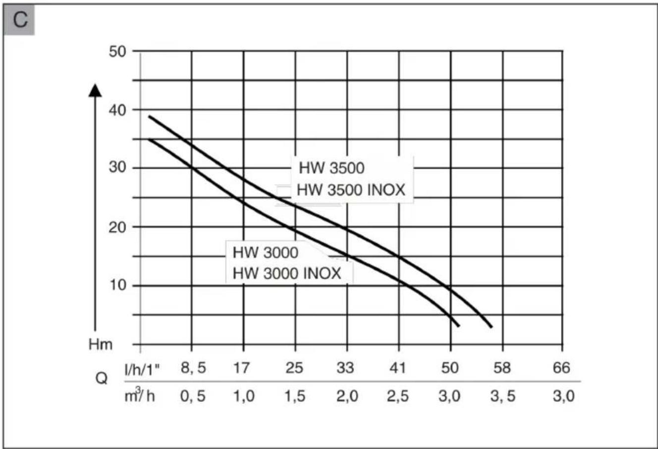
| Q (l/h/1" / m³/h) | HW 3500 | HW 3500 INOX | HW 3000 | HW 3000 INOX | | ----------------- | ------- | ------------ | ------- | ------------ | | 8,5 | 39 | 35 | - | - | | 17 | 32 | 28 | - | - | | 25 | 25 | 22 | - | - | | 33 | 18 | 16 | - | - | | 41 | 12 | 10 | - | - | | 50 | 8 | 6 | - | - | | 58 | 4 | 2 | - | - | | 66 | - | - | - | - || HW 3000(Art. Nr. 112 845)HW 3000 INOX(Art. Nr. 112 846) | HW 3500(Art. Nr. 112 847)HW 3500 INOX(Art. Nr. 112 848) | HW 3300 INOX(Art. Nr. 113 512) | |
 | 650 W 850 W 810 W | ||
 | 230 V AC/50 Hz 230 V AC/50 Hz 230 V AC/50 Hz | ||
 | X 4 X 4 X 4 | ||
 | 76 dB (A) 77 dB (A) 77 dB (A) | ||
 | 8 m 8 m 8 m | ||
 | 35 m / 3,5 bar 38 m / 3,8 bar 38 m / 3,8 bar | ||
 | 3100 l/h 3400 l/h 3200 l/h | ||
 | 35 °C 35 °C 35 °C | ||
 | 1,5 / 2,8 bar 1,5 / 2,8 bar 1,5 / 2,8 bar | ||
 | 1" 1" 1" | ||
 | HW 3000: 11 kgHW 3000 INOX: 10,8 kg | HW 3500: 11,7 kgHW 3500 INOX: 11,5 kg | 11,5 kg |
 | 1 1 1 | ||
 | 17 | 17 | 17 | | ||
Intertek Testing & Certification Ltd Milton Keynes 4 Davy Ave, Knowlhill, MK5 8NL Milton Keynes United Kingdom
Kötz, 12.03.2018

Daniel Trumpp Chief Technology Officer
TRANSLATION OF THE ORIGINAL INSTRUCTIONS FOR USE
Contents
1 About these operating instructions...... 13
1.1 Symbols on the title page 13
1.2 Legends and signal words...... 13
2 Product description .... 14
2.1 Scope of supply 14
2.2 Product overview 14
2.3 Function.... 14
2.4 INOX (stainless steel).... 14
2.5 Safety and protective devices...... 14
2.6 Pressure sensor.... 14
2.7 Intended use.... 14
2.8 Possible misuse.... 14
3 Safety instructions.... 15
3.1 General safety warnings.... 15
3.2 Electrical safety.... 15
4 Installation.... 15
4.1 Install the pump 15
4.2 Connect the suction line 15
4.3 Mounting the pressure line (2)...... 16
5 Start-up 16
5.1 Check the air pressure in the storage vessel.... 16
5.2 Fill the pump 16
6 Operation 16
6.1 Switching the pump on 16
6.2 Switching the pump off 16
7 Maintenance and care.... 17
7.1 Check the air pressure in the storage vessel.... 17
7.2 Cleaning the pump.... 17
7.3 Remove blockages 17
8 Help in case of malfunction.... 17
9 Storage.... 18
10 Disposal 18
11 After-Sales/Service 18
12 Warranty 19
13 Translation of the original EU/EC declaration of conformity 19
1 ABOUT THESE OPERATING INSTRUCTIONS
The German version is the original operating instructions. All additional language versions are translations of the original operating instructions.
- Keep these operating instructions in a safe place at all times so that they can be consulted if you need any information about the appliance.
■ Only pass on the appliance to other persons together with these operating instructions.
■ Comply with the safety and warning information in these operating instructions.
1.1 Symbols on the title page
Symbol Meaning

It is essential to read through these operating instructions carefully before start-up. This is essential for safe working and trouble-free handling.

Operating instructions

To avoid electric shock, do not damage or cut the power cable!
1.2 Legends and signal words
⚠️ DANGER! Denotes an imminently dangerous situation which will result in fatal or serious injury if not avoided.
WARNING! Denotes a potentially dangerous situation which can result in fatal or serious injury if not avoided.
CAUTION! Denotes a potentially dangerous situation which can result in minor or moderate injury if not avoided.
IMPORTANT! Denotes a situation which can result in material damage if not avoided.
NOTE Special instructions for ease of understanding and handling.
2 PRODUCT DESCRIPTION
Various models of pumps are described in these operating instructions. Identify your model from the identification plate.
2.1 Scope of supply
The pump is supplied with pressure switch, pressure gauge and mains cable.
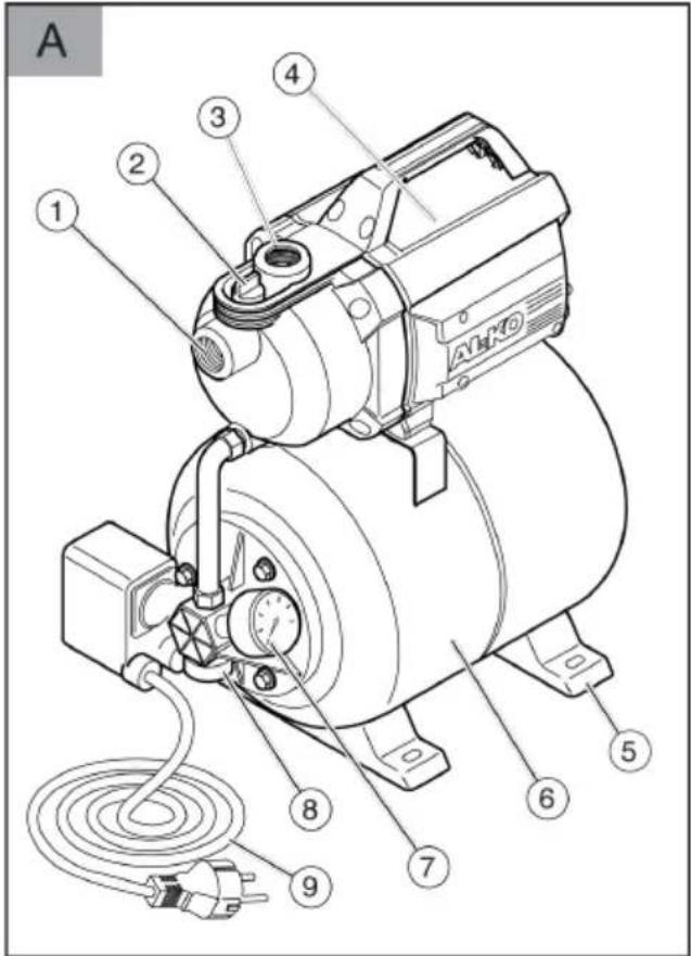
2.2 Product overview
No. Component
| 1 Pump inlet/suction line connection |
| 2 Filling screw |
| 3 Pump outlet/pressure line connection |
| 4 Motor housing |
| 5 Pump base |
| 6 Storage vessel |
| 7 Pressure gauge |
| 8 Drain plug |
| 9 Mains cable |
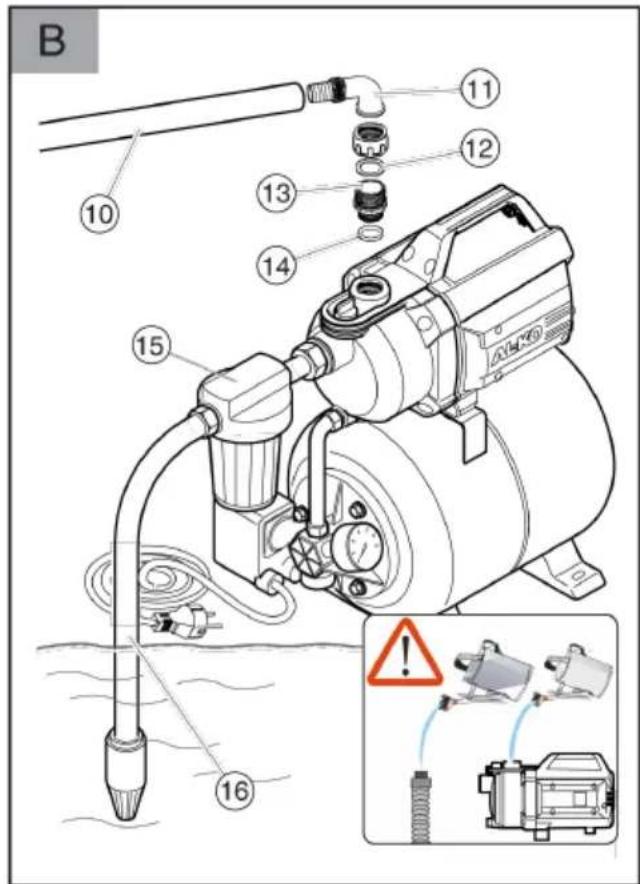
| 10 Pressure line (accessory) |
| 11 Elbow nipple (accessory) |
| 12 Seal (accessory) |
| 13 Connecting nipple (accessory) |
| 14 Seal (accessory) |
| 15 Filter (accessory) |
| 16 Suction line (accessory) |
2.3 Function
The device is used for supplying water in and around the house. After commissioning, the device switches the pump on and off, depending on the pressure. The pump draws water via the suction line and conveys it to the storage vessel. When the storage vessel is full, the pump switches off again. If water is drawn off, the pump switches on again automatically and conveys water to the tapping point. The storage vessel is then filled again.
2.4 INOX (stainless steel)
Pumps with the designation "INOX" are made of stainless steel. This does not affect their design or function.
2.5 Safety and protective devices
Thermal protection switch
The pump is fitted with a thermal protection switch which switches the motor off in the event of overheating. After a cooling-down phase of approx. 15 - 20 minutes the pump switches on again automatically.
2.6 Pressure sensor
The pump is equipped with a pressure sensor. This sensor automatically switches the pump off and on when the set pressure is reached.
■ Set pressure: see technical data.
2.7 Intended use
The pump is intended for private use in house and garden. It must only be operated within the scope of its usage limitations in accordance with the technical data.
The pump is suitable for:
■ Watering the garden and premises
■ Domestic water supplies
■ Water supply pressure boosting.
NOTE The local regulations must be observed if the pressure of the water supply is increased. Information is available from your local plumbing specialist.
The pump is suited exclusively for the conveying of the following fluids:
Clear water, rainwater
Any use not in accordance with this designated use shall be regarded as misuse.
2.8 Possible misuse
The pump must not be used in continuous operation. It is not suitable for conveying:
- Drinking water
Salt water
Foodstuffs
■ Dirty water containing paper and textile residues
■ aggressive media, chemicals
■ corrosive, flammable, explosive or fuming fluids
■ fluids that are hotter than 35 °C
■ water containing sand and abrasive fluids.
3 SAFETY INSTRUCTIONS
⚠️ DANGER! Danger from contact with live parts! A defect in the pump or the extension cable can result in serious injury!
■ Disconnect the connector plug from the mains immediately.
■ Connect the device via an earth leakage circuit breaker with a rated leakage current of < 30 mA.
WARNING! Risk of injury. Defective and disabled safety and protective devices can result in serious injury.
■ Have any defective safety and protective devices repaired.
■ Never disable safety and protective devices.
CAUTION! Danger of injury from hot water After extended use against the closed pressure side (> 10 min.), the water in the pump can become very hot and may escape uncontrolled!
■ Disconnect the pump from the mains supply and allow the pump and water to cool down.
- Check the water level on the suction side.
■ Check the leak-tightness of the lines.
- Check the installation of the suction and pressure lines.
- Put the pump into operation again only after all the faults have been remedied!
3.1 General safety warnings
This appliance can be used by children of 8 years and older and by persons with reduced physical, sensory or mental capabilities, or those lacking experience and knowledge, if they are supervised or have been instructed with regard to the safe use of the appliance and the ensuing risks. Children must not be allowed to play with the appliance. Cleaning and maintenance must not be carried out by children without supervision.
■ People with very strong and complex restrictions may have needs that exceed the instructions described here.
■ Never lift, transport or affix the pump by the mains cable. Do not pull the mains cable in order to pull the mains plug out of the socket.
■ Unauthorised modifications or conversions to the pump are prohibited. Repairs may only be carried out by our customer service.
■ Disconnect the mains plug before working on the device. Protect the mains plug against moisture.
■ Only use the pump and extension cable if they are in flawless technical condition. Damaged appliances must not be operated.
- Maintain a safe distance to persons or animals or switch off the pump if animals approach.
3.2 Electrical safety
■ The pump may not be operated while people are in the pool or pond.
The mains voltage at your location must comply with the information regarding mains voltage in the Technical Data. Do not use any other supply voltage.
The appliance must only be operated on electrical equipment in accordance with DIN/VDE 0100, parts 737, 738 and 702. A circuit breaker of 10 A must be installed for fuse protection.
- Only use an extension cords which are designed for outdoor use – minimum cross-section 3 x 1.5 mm ^2 , quality of H07RN-F as per DIN 57282/57245 with splash-proof plug socket. Always fully unwind cable drums.
- Check the condition of you extension cable prior to every use.
4 INSTALLATION
4.1 Install the pump
- Prepare a level and sturdy installation location.
- Install the pump horizontally and where it will not be flooded.
■ The pump must be protected from rain and direct water jets.
NOTE In day-to-day operation (automatic mode), suitable measures must be taken to exclude the possibility of flooding of rooms as a result of malfunctions in the pump.
4.2 Connect the suction line
NOTE We recommend the installation of flexible lines at the pump inlet to prevent mechanical pressure or tension being exerted on the pump.
-
Select the length of the suction line such that the pump cannot run dry. The suction line must always be at least 30 cm under the water surface.
-
Connect the suction line. Ensure that the connection is tight, but take care not to damage the thread.
- Always lay the suction line with an upward gradient.
NOTE If the suction head is more than 4 m, a suction hose with a diameter larger than 1" must be installed. We recommend the use of an AL-KO suction unit with suction hose, suction filter and flow-back stop. Ask your specialist dealer.
4.3 Mounting the pressure line (2)
- Screw connecting nipple (13) with seal (14) into pump outlet (3).
- Screw elbow nipple (11) with seal (12) onto connecting nipple (13) and turn the elbow nipple in the required direction.
- Connect pressure line (10) to elbow nipple (11).
- Open all shut-off devices (valves, spray nozzles, water cock) in the pressure line.
5 START-UP
5.1 Check the air pressure in the storage vessel
IMPORTANT! Danger of damage to the pump! The pump may only be operated with a diaphragm storage pressure of 1.5 - 1.7 bar in the storage vessel. Other diaphragm storage pressures can cause equipment damage.
- Check the air pressure at the valve on the back of the storage vessel before commissioning.
- Open the cover on the rear of the storage vessel.
- Check the air pressure at the valve using an air pump or tyre filler equipped with a pressure gauge.
- Correct the air pressure to 1.5 - 1.7 bar, if necessary.
- Close the cover on the rear of the storage vessel again.
- Putting the pump into operation.
5.2 Fill the pump
IMPORTANT! Danger of damage to the pump! Dry running will destroy the pump!
The pump must be filled with water up to the overflow before each use so that it can draw water immediately.
- Open filling screw (2) using filter wrench (19/A). (Not for INOX models)
- Pour in water through the filling screw until the pump housing is full.
- Screw in filling screw. (Not for INOX models)
6 OPERATION
6.1 Switching the pump on
- Open all shut-off devices (valve, spray nozzle, water cock) in the pressure line (10).
- Insert the plug of the mains cable into the power socket. The pumps starts to pump.
- Close the shut-off device in the pressure line when there are no more air bubbles in the escaping water.
The pump switches off automatically after building up the pressure and reaching the switch-off pressure.
■ The pump is ready for operation.
6.2 Switching the pump off
- Remove the mains plug from the plug socket.
- Close all the shut-off devices in the pressure line.
CAUTION! Danger of injury from hot water After extended use against the closed pressure side (> 10 min.), the water in the pump can become very hot and may escape uncontrolled!
■ Disconnect the pump from the mains supply and allow the pump and water to cool down.
- Put the pump into operation again only after all the faults have been remedied!
The risk of injury from hot water can arise in the event of:
■ Incorrect installation,
■ Closed pressure side,
- Lack of water in the suction line, or
■ Defective pressure switch.
Procedure
- Disconnect the pump from the mains supply and allow the pump and water to cool down.
- Check the pump, installation and water level.
- Put the pump into operation again only after all the faults have been remedied!
7 MAINTENANCE AND CARE
7.1 Check the air pressure in the storage vessel
NOTE Check the air pressure in the storage vessel at regular intervals. It must not exceed 1.5 bar (see Section "Commissioning: Checking the Air Pressure in the Storage Vessel").
- Disconnect the pump from the mains supply and secure to prevent restarting. The pump stops automatically.
- Open a shut-off device (valve, spray nozzle, water cock) in pressure line (10).
- Drain water until the pump is completely empty.
- Open the cover on the rear of the storage vessel.
- Check the air pressure at the valve using an air pump or tyre filler equipped with a pressure gauge. Correct the air pressure, if necessary.
- Close the cover on the rear of the storage vessel again.
- Put the pump into operation again.
7.2 Cleaning the pump
i NOTE After conveying swimming pool water containing chlorine or fluids that leave residues, the pump must be flushed out with clear water.
- Disconnect the pump from the mains supply and secure to prevent restarting. The pump stops automatically.
- Flush the pump with clear water.
- Insert the mains plug into the power socket.
- Turn on the pump at the on / off switch. The pump starts automatically.
7.3 Remove blockages
- Disconnect the pump from the mains supply and secure to prevent restarting.
- Disconnect suction line from pump inlet.
- Connect pressure line to the water line.
- Allow water to run through the pump housing until the blockage is removed.
- Switch on the pump briefly to check whether it runs smoothly.
- Put the pump into operation as described.
8 HELP IN CASE OF MALFUNCTION
DANGER! Danger of electric shock!
There is a risk of electric shock when working on the pump.
■ Disconnect the mains plug before starting any fault remedying work.
■ Faults in the electrical system must be rectified by a qualified electrician.
i NOTE In the event of faults that you cannot rectify, please contact our Customer Service department.
| Malfunction Possible cause | Remedy | |
| Motor does not run. Impeller blocked. Cleaning the pump. Release the motor shaft of the impeller with a screw-driver. | ||
| Pump running but does not feed. | Water level too low. Submerge the suction line deeper. | |
| Pump drawing air into the suction line. | Check all the connections of the suction line for leaks.Replace seal ring. | |
| Pump drawing in air. Check all connections and the cover on the filter for leaks. | ||
| Blockage on the suction side. Remove dirt from the suction area. | ||
| Pressure line closed off. Open the pressure lone. | ||
| Pump has been running dry. Fill the pump housing with water. | ||
| Pump switches on and off frequently. | Diaphragm is damaged. Have the diaphragm replaced by AL-KO Service Department. | |
| Low air pressure in the storage vessel. | Top up the air in the storage vessel.(Set the diaphragm pressure to 1.5 bar). | |
| Pump does not switch off with a closed pressure line. | Pump drawing air, water shortage on suction side. | Switch pump off and allow to cool. |
| Delivery rate too low. Water volume on the suction side to little | Throttle back the pump to adapt the flow rate. | |
| Hose diameter too small. Use a larger pressure line. | ||
| Blockage on the suction side. Remove dirt from the suction area.Replace the filter. | ||
| Suction head too large. Check suction head, observe max.suction head, see Technical Data. | ||
9 STORAGE
- Drain suction line (16) and pressure line (10).
- Unscrew drain plug (8) and allow the water to drain out of the pump. The water in storage vessel (6) is forced out at the same time by the air bellows.
- Screw in drain plug (8) again and store pump and accessories in a frost-proof place.
i NOTE If there is the danger of frost, the system must be completely drained and the pump must be stored in a frost-proof place.
10 DISPOSAL

Electrical and electronic appliances do not belong in household waste, but should be collected and disposed of separately.
Packaging, equipment and accessories are made from recyclable materials, and must be disposed of accordingly.
11 AFTER-SALES/SERVICE
In the event of questions of warranty, repair or spare parts, please contact your nearest AL-KO Service Centre. These can be found on the Internet at: www.alko-garden.com/service-contacts
Further information on spare parts can be found at: www.alko-garden.com/spareparts
12 WARRANTY
We will remedy any material or manufacturing defects discovered in the device during the statutory period of limitation for claims for defects by repair or replacement at our discretion. The period of limitation is determined in each case by the law of the country in which the device was purchased.
Our warranty promise applies only if:
■ These operating instructions are observed
■ The device is handled correctly
■ Original spare parts have been used
The warranty becomes void in the case of:
■ Unauthorised repair attempts
■ Unauthorised technical modifications
■ Use for other than the intended purpose
The warranty does not include:
■ Paint damage attributable to normal wear
■ Wear parts that are marked with a box (x) on the spare parts card
The warranty period commences with the purchase by the first end user. The date on the proof of purchase is decisive. In the event of a warranty claim, please contact your dealer or the nearest authorised customer service centre with this declaration and the original proof of purchase. This declaration does not affect the purchaser's statutory claims for defects against the vendor.
13 TRANSLATION OF THE ORIGINAL EU/EC DECLARATION OF CONFORMITY
We hereby declare that this product in its marketed form conforms to the requirements of the harmonised EU Directives, EU safety standards and the product-specific standards.
Product
| Domestic water system |
| Serial number |
| G3043045 |
Manufacturer
Duly authorised person for technical file
| Ismail Kabasakal |
| Ichenhauser Str. 14 |
| D-89359 Kötz |
Type
| HW 3000 (INOX) |
| HW 3500 (INOX) |
| HW 3300 INOX |
EU directives
| 2014/35/EU |
| 2014/30/EU |
| 2000/14/EC |
| 2011/65/EU |
| 2014/68/EU |
Applied standards
| EN 60335-1:2012 |
| EN 60335-2-41:2012 |
| EN 62233:2008 |
| EN 55014-1:2012 |
| EN 55014-2:2016 |
| EN 61000-3-2:2014 |
| EN 61000-3-3:2014 |
Sound power level
| EN ISO 3744 |
Conformity evaluation
| 2000/14/EC Annex V |
| EN 61000-3-2:2014 |
measured/guaranteed
HW 3000 (INOX): 74 / 76 dB(A)
HW 3500 (INOX): 76 / 77 dB(A)
HW 3300 INOX: 76 / 77 dB(A)

2015
Notified body
| Intertek Testing & Certification Ltd |
| Milton Keynes 4 Davy Ave, Knowlhill, MK5 8NL |
| Milton Keynes United Kingdom |
Kötz, 12 Mar 2018

Daniel Trumpp
Chief Technology Officer
VERTALING VAN DE ORIGINELE GEBRUIKERSHANDLEIDING
Inhoudsopgave
2 PRODUCTOMSCHRIJVING
Intertek Testing & Certification Ltd Milton Keynes 4 Davy Ave, Knowlhill, MK5 8NL Milton Keynes United Kingdom
Kötz, 2018-03-12

Daniel Trumpp
Chief Technology Officer
TRADUCTION DE LA NOTICE D'UTILISATION ORIGINALE
Table des matières
Intertek Testing & Certification Ltd
Milton Keynes 4 Davy Ave,
Knowlhill, MK5 8NL
Milton Keynes
United Kingdom
Kötz, 2018-03-12

Daniel Trumpp
Chief Technology Officer
Intertek Testing & Certification
Ltd
Milton Keynes 4 Davy Ave,
Knowlhill, MK5 8NL
Milton Keynes
United Kingdom
Normas aplicadas
EN 60335-1:2012
EN 60335-2-41:2012
EN 62233:2008
EN 55014-1:2012
EN 55014-2:2016
EN 61000-3-2:2014
EN 61000-3-3:2014
Kötz, 2018-03-12
Daniel Trumpp
Chief Technology Officer
TRADUZIONE DEL MANUALE PER L'USO ORIGINALE
Sommario
Intertek Testing & Certification Ltd Milton Keynes 4 Davy Ave, K- nowlhill, MK5 8NL Milton Keynes United Kingdom
Kötz, 2018-03-12

Daniel Trumpp
Chief Technology Officer
PREVOD ORIGINALNIH NAVODIL
Kazalo vsebine
11 SERVISNA SLUŽBA/SERVIS
Intertek Testing & Certification
Ltd
Milton Keynes 4 Davy Ave,
Knowlhill, MK5 8NL
Milton Keynes
United Kingdom
Kötz, 2018-03-12

Daniel Trumpp
Chief Technology Officer
PRIJEVOD ORIGINALNIH UPUTA ZA UPORABU
Sadržaj
1 Informacije o Uputama za uporabu...... 57
1.1 Simboli na naslovnoj stranici .... 57
1.2 Objasnjenja oznaka i signalnih riječi.. 57
2 Opis proizvoda 58
2.1 Opseg isporuke.... 58
2.2 Pregled proizvoda.... 58
2.3 Funkcija 58
2.4 INOX....58
2.5 Sigurnosni i zaštitni uređaj...... 58
2.6 Tlačni senzor 58
2.7 Namjenska uporaba.... 58
2.8 Moguća nepravilna uporaba .... 58
3 Sigurnosne napomene.... 59
3.1 Opće sigurnosne napomene.... 59
3.2 Električna sigurnost 59
4 Montaža 59
Intertek Testing & Certification Ltd Milton Keynes 4 Davy Ave, Know- lhill, MK5 8NL
Milton Keynes
United Kingdom
Kötz, 2018-03-12
Daniel Trumpp
Chief Technology Officer
PŘEKLAD ORIGINÁLNÍHO NÁVODU K POUŽITÍ
Obsah
Intertek Testing & Certification Ltd
Milton Keynes 4 Davy Ave,
Knowlhill, MK5 8NL
Milton Keynes
United Kingdom
Kötz, 2018-03-12

Daniel Trumpp
Chief Technology Officer
PREKLAD ORIGINÁLNEHO NÁVODU NA POUŽITIE
Obsah
1 O tomto návode na obsluhu.... 79
1.1 Symboly na titulnej strane.... 79
1.2 Vysvetlenie symbolov a signálne slo-
vá....79
Intertek Testing & Certification Ltd Milton Keynes 4 Davy Ave, Knowlhill, MK5 8NL Milton Keynes United Kingdom
Kötz, 2018-03-12

Daniel Trumpp
Chief Technology Officer
AZ EREDETI KEZELÉSI ÚTMUTATÓ FORDÍTÁSA
Tartalomjegyzék
Intertek Testing & Certification Ltd Milton Keynes 4 Davy Ave, Knowlhill, MK5 8NL
Milton Keynes
United Kingdom
Kötz, 2018-03-12
Daniel Trumpp
Chief Technology Officer
OVERSÆTTELSE AF DEN ORIGINALE BRUGSANVISNING Indholdsfortegnelse
Intertek Testing & Certification Ltd
Milton Keynes 4 Davy Ave,
Knowlhill, MK5 8NL
Milton Keynes
United Kingdom
Kötz, 2018-03-12
Daniel Trumpp
Chief Technology Officer
ÖVERSÄTTNING AV ORIGINALBRUKSANVISNING
Intertek Testing & Certification Ltd
Milton Keynes 4 Davy Ave,
Knowlhill, MK5 8NL
Milton Keynes
United Kingdom
Kötz, 2018-03-12
Daniel Trumpp
Chief Technology Officer
OVERSETTELSE AV DEN ORIGINALE BRUKSANVISNINGEN
Innhold
7 VEDLIKEHOLD OG PLEIE
7.1 Kontrollere lufttrykket i vanntanken
Intertek Testing & Certification Ltd Milton Keynes 4 Davy Ave, Knowlhill, MK5 8NL
Milton Keynes
United Kingdom
Kötz, 2018-03-12

Daniel Trumpp
Chief Technology Officer
ALGUPÄRASE KASUTUSJUHENDI TÖLGE Sisukord
www.al-ko.com/service-contacts
12 GARANTII
Intertek Testing & Certification Ltd
Milton Keynes 4 Davy Ave,
Knowlhill, MK5 8NL
Milton Keynes
United Kingdom
Kötz, 2018-03-12
Daniel Trumpp
Chief Technology Officer
ORIGINALIOS NAUDOJIMO INSTRUKCIJOS VERTIMAS
Turinys
| Intertek Testing & Certification Ltd |
| Milton Keynes 4 Davy Ave, Knowlhill, MK5 8NL |
| Milton Keynes |
| United Kingdom |
Kötz, 2018-03-12

Daniel Trumpp Chief Technology Officer
ORIĞINĀLĀS LIETOŠANAS INSTRUKCIJAS TULKOJUMS
Saturs
1 Par šo lietošanas instrukciju.... 135
Intertek Testing & Certification Ltd
Milton Keynes 4 Davy Ave,
Knowlhill, MK5 8NL
Milton Keynes
United Kingdom
Daniel Trumpp
Chief Technology Officer
Intertek Testing & Certification Ltd Milton Keynes 4 Davy Ave, Knowlhill, MK5 8NL Milton Keynes United Kingdom
Kötz, 2018-03-12
Daniel Trumpp
Chief Technology Officer
Intertek Testing & Certification Ltd
Milton Keynes 4 Davy Ave,
Knowlhill, MK5 8NL
Milton Keynes
United Kingdom
Kötz, 2018-03-12
Daniel Trumpp
Chief Technology Officer
Intertek Testing & Certification
Ltd
Milton Keynes 4 Davy Ave,
Knowlhill, MK5 8NL
Milton Keynes
United Kingdom
Chief Technology Officer
Russia
Imported by: AL-KO Gardentech UK Ltd, Murray way, Wincanton, Somerset, BA9 9RS / UK | +44 (0) 1963 828055 shop.uk@al-ko.com | www.alko-garden.uk
AL-KO Service: www.al-ko.com/service-contacts

- Inhaltsverzeichnis
- TRANSLATION OF THE ORIGINAL INSTRUCTIONS FOR USE
- Contents
- ABOUT THESE OPERATING INSTRUCTIONS
- Symbols on the title page
- Symbol Meaning
- Legends and signal words
- PRODUCT DESCRIPTION
- Scope of supply
- Product overview
- Function
- INOX (stainless steel)
- Safety and protective devices
- Thermal protection switch
- Pressure sensor
- Intended use
- Possible misuse
- SAFETY INSTRUCTIONS
- General safety warnings
- Electrical safety
- INSTALLATION
- Install the pump
- Connect the suction line
- Mounting the pressure line (2)
- START-UP
- Check the air pressure in the storage vessel
- Fill the pump
- OPERATION
- Switching the pump on
- Switching the pump off
- Procedure
- MAINTENANCE AND CARE
- Check the air pressure in the storage vessel
- Cleaning the pump
- Remove blockages
- HELP IN CASE OF MALFUNCTION
- DANGER! Danger of electric shock!
- STORAGE
- DISPOSAL
- AFTER-SALES/SERVICE
- WARRANTY
- TRANSLATION OF THE ORIGINAL EU/EC DECLARATION OF CONFORMITY
- VERTALING VAN DE ORIGINELE GEBRUIKERSHANDLEIDING
- Inhoudsopgave
- PRODUCTOMSCHRIJVING
- TRADUCTION DE LA NOTICE D'UTILISATION ORIGINALE
- Table des matières
- Normas aplicadas
- TRADUZIONE DEL MANUALE PER L'USO ORIGINALE
- Sommario
- PREVOD ORIGINALNIH NAVODIL
- Kazalo vsebine
- SERVISNA SLUŽBA/SERVIS
- PRIJEVOD ORIGINALNIH UPUTA ZA UPORABU
- Sadržaj
- PŘEKLAD ORIGINÁLNÍHO NÁVODU K POUŽITÍ
- Obsah
- PREKLAD ORIGINÁLNEHO NÁVODU NA POUŽITIE
- AZ EREDETI KEZELÉSI ÚTMUTATÓ FORDÍTÁSA
- Tartalomjegyzék
- OVERSÆTTELSE AF DEN ORIGINALE BRUGSANVISNING Indholdsfortegnelse
- ÖVERSÄTTNING AV ORIGINALBRUKSANVISNING
- OVERSETTELSE AV DEN ORIGINALE BRUKSANVISNINGEN
- Innhold
- VEDLIKEHOLD OG PLEIE
- Kontrollere lufttrykket i vanntanken
- ALGUPÄRASE KASUTUSJUHENDI TÖLGE Sisukord
- GARANTII
- ORIGINALIOS NAUDOJIMO INSTRUKCIJOS VERTIMAS
- Turinys
- ORIĞINĀLĀS LIETOŠANAS INSTRUKCIJAS TULKOJUMS
- Saturs
- Russia
Brand : AL-KO
Model : HW 3500
Category : Water pump