Park Pro 340 IX - Tractor STIGA - Free user manual and instructions
Find the device manual for free Park Pro 340 IX STIGA in PDF.

| Product type | Riding lawn mower, front cutting deck |
| Model | Park Pro 340 IX |
| Brand | Stiga |
| Intended use | Grass cutting, leisure use |
| Engine type | 4-stroke petrol (according to version: Honda GXV 630/660/690, B&S 8270 or Vanguard 18HP) |
| Fuel | Unleaded petrol |
| Transmission type | Hydrostatic 4-wheel drive |
| Steering | Articulated, reduced turning radius |
| Cutting width | Variable depending on installed cutting deck (see accessory manual) |
| Cutting height | Electrically adjustable from the driver's seat |
| Maximum slope | 10° (17%) |
| Forward speed | Variable, pedal controlled |
| Parking brake | Pedal with locking lever |
| Battery | 12V, chargeable by engine or external charger |
| Display | Hour meter (Mod. 340 X) or multifunction display (Mod. 740 IOX / 540 IX) |
| Compatible accessories | Trailer, fertilizer, leaf collector, spreader, rake, snow chains, snow plow, sweeper, aerator, etc. |
| Hydraulic outlets | 2 auxiliary outlets (on some models) |
| Hydraulic lift | For front accessories, lever controlled |
| Weight | Variable depending on equipment (see nameplate) |
| Dimensions (L x W x H) | Consult manual for exact values |
| Guaranteed sound level | See nameplate |
| Maintenance | Engine oil change every 50-100h, air filter every 25-100h, spark plug each season |
| Warranty | 2 years (parts and labor), subject to general conditions |
Frequently Asked Questions - Park Pro 340 IX STIGA
User questions about Park Pro 340 IX STIGA
0 question about this device. Answer the ones you know or ask your own.
Ask a new question about this device
Download the instructions for your Tractor in PDF format for free! Find your manual Park Pro 340 IX - STIGA and take your electronic device back in hand. On this page are published all the documents necessary for the use of your device. Park Pro 340 IX by STIGA.
USER MANUAL Park Pro 340 IX STIGA
natural_image
Yellow and black golf rOLL tractor with visible wheels and head cover (no text or symbols)Park series 4WD
Pro 740 IOX
Pro 540 IX
Pro 340 IX
Type P 901 PH
TOSAERBA CON CONDUCENTE A BORDO SEDUTO
КОСАЧКА СЪС СЕДНАЛ ВОДАЧ
TRAKTORSKA KOSILICA (TRAKTORČIĆ)
SEKAČKA SE SEDÍCÍ OBSLUHOU
HAVETRAKTOR/HAVETRAKTOR MED FRONTKLIPPER (FM)
AUFSITZMÄHER (RASENMÄHER MIT FAHRERSITZ MIT SITZENDEM BENUTZER)
5
[740 IOX; 540 IX]

natural_image
3D mechanical assembly diagram showing a component with mounting holes and a suspended structure labeled A (no text or symbols present)
[340 IX]
natural_image
Mechanical assembly diagram showing a device with labeled parts (A), no readable text or symbols present.6

natural_image
Illustration of a vehicle's seat assembly with no text or symbols7
[740 IOX; 540 IX]
8

natural_image
Technical line drawing of a car seat assembly with labeled components (no text or symbols present)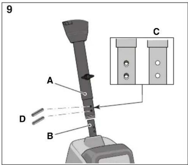

![14 [740 IOX; 540 IX] D E M N O A G F L I H P B C N = AUX 1 O = AUX 2 [340 IX] N A G F E I H D P B C](/content/2026/03/489575/images/d1a4c5783984167cd5a423a1ea3a0ceebf532c371ab578cee397ab57fecb295f.jpg)
![15 [740 IOX; 540 IX] A D B C E F G 12V ON/OFF I PN HML](/content/2026/03/489575/images/fb0e7f4dc53f16227ec472c44b2fb985d4048902ba88e65e216063c93a4d3d04.jpg)
natural_image
Illustration of a small agricultural robot with labeled parts, shown from an inset view (no text or symbols on the robot itself)
![18 [740 IOX] A AUX 1 AUX 2 B C](/content/2026/03/489575/images/bf58c98ea810c4d8d341a2a0107cc04596ce0fdf208b2b77d61ea0a273788f1d.jpg)
natural_image
Illustration of a mechanical switch or bracket device on a curved surface, with no visible text or symbols.![20 A B [740 IOX; 540 IX]](/content/2026/03/489575/images/a3f914a86689e5fb475a18f867d2515e97ce5b9525b7794b17aa2260508b428b.jpg)


natural_image
Mechanical diagram of a vehicle wheel assembly with labeled component A (no text or symbols beyond labels)
natural_image
Mechanical assembly diagram showing a tire and bracket component with a pull arrow (no text or symbols)

![26 [Honda GXV 630; 660; 690] A B C D Full](/content/2026/03/489575/images/3c592bf11c8d1c14934760c7ce6a61f17e8ecafc751e15191d6f9d37da565d33.jpg)
![27 [B&S Vanguard 18 HP] Full C B A](/content/2026/03/489575/images/9d438be8c6f29c1845c6e1d11da6d0d270374ae0b55d7d2a35d75b8d1f6345e7.jpg)
![27X [B&S Vanguard 18 HP] A B](/content/2026/03/489575/images/203c4568b2c09ecf933eec945b88c4852e9d16aa0f6c543ea435c42bdffb9332.jpg)
![29 [B&S 8270] Full](/content/2026/03/489575/images/08a6b8044bb3e5672a8115002bf9f2b4374129d91e928006b6d8279fcbb0e257.jpg)
![29X [B&S 8270] E A B C D](/content/2026/03/489575/images/dec2633ca7b2ed1c49ca90f6fe3f0aa2af22c9efcf10cd1dd6649a49e2985728.jpg)
28

natural_image
Mechanical assembly diagram showing a tire with a clamp and labeled component E (no text or symbols beyond label)

natural_image
Illustration of a golf mobility vehicle with visible wheels and seat (no text or symbols)


0 TABELLA DATI TECNICI
| [1] | Type | |
| [2] | Model | |
| [3] | Engine | |
| [4] | Engine displacement | |
| [5] | Power | |
| [6] | Engine revs | |
| [7] | Electrical System | |
| [8] | Battery | |
| [9] | Rear accessory power | |
| [10] | Fuel | |
| [A] | Unleaded petrol | |
| [11] | Fuel tank capacity | |
| [12] | Engine oil | |
| [13] | Engine oil, service category | |
| [A] | SJ or higher | |
| [14] | Engine oil tank capacity, without filter change | |
| [15] | Engine oil tank capacity, with filter change | |
| [16] | Transmission fluid | |
| [17] | Quantity of transmission fluid required for fluid change | |
| [18] | Spark plug | |
| [19] | Spark gap | |
| [20] | Tyres | |
| [21] | Tyre pressure | front |
| rear | ||
| [22] | Cutting height and width | |
| [A] | For the cutting height, please refer to the "Technical Data Table" in the cutting device assy manual. | |
| [23] | Forward travel speed (indicative) | |
| [24] | Reverse travel speed (indicative) | |
| [25] | Weight | |
| [26] | Overall dimensions | |
| [27] | A = Length | |
| [28] | B = Pitch | |
| [29] | C = Height | |
| [30] | D = Width | |
| [31] | Admissible load on towing device (maximum vertical weight) | |
| [32] | Admissible load for towing device (maximum towing weight) | |
| [33] | Maximum admissible tilt | |
| [34] | Display | |
| [35] | Hour meter display | |
| [36] | Standard carrier | |
| [37] | Carrier payload | |
| [38] | Hydraulic connectors (auxiliary) | |
| [39] | Measured sound power level | |
| [40] | Uncertainty | |
| [41] | Guaranteed sound power level | |
| [42] | Sound pressure level |
| [43] | Uncertainty |
| [44] | Vibration value in the driver's seat |
| [45] | Uncertainty |
| [46] | Vibration value in the steering wheel |
| [47] | Uncertainty |
| [48] | ACCESSORIES AVAILABLE ON REQUEST |
| [49] | Description |
| [50] | Trailer |
| [51] | Fertilizer spreader |
| [52] | Grass and leaf collector |
| [53] | Sand spreader |
| [54] | Rake |
| [55] | Snow chains |
| [56] | Mud / Snow wheels |
| [57] | Cutting device assy |
| [58] | Front harrow |
| [59] | "Shredder |
| [60] | Snow thrower |
| [61] | Front sweeper |
| [62] | Blade type snow plough |
| [63] | Aerator/scarifier |
| [64] | Rear wheel counterweights |
| [65] | Rear lifting assembly for accessories |
| [66] | Carrier [340 IX] |
| [67] | TABLE FOR CORRECT ACCESSORY COMBINATIONS |
| [68] | REAR ACCESSORIES |
| [69] | FRONT ACCESSORIES |
| [70] | Accessory |
6.17 SOLLEVATORE ACCESSORI IDRAULICO (1:G)
9.5.2 Controllo / rabbocco (29; 27) (Mod. B&S 8270; B&S VANGUARD 18HP)

1.1 ROZVRŽENÍ MANUÁLU 4
1.2 SYMBOLY POUŽITÉ V NÁVODU. 4
1.3 USCHOVÁVANÍ MANUÁLU 4
2 SEZNÁMENÍ SE SE STROJEM 4
2.1 CHARAKTERISTIKY STROJE. 4
2.2 PŘEDPOKLÁDANÉ POUŽITÍ ..... 4
2.2.1 Definování typu uživatele . . . . . . . . . . . . . . . . . . . . . . . . . . . . . . . . . . . . . . . . . . . . . . . . 5
2.3 NEVHODNÉ POUŽITÍ 5
2.4 BEZPEČNOSTNÍ OZNAČENÍ (4). 5
2.5 IDENTIFIKAČNÍ ŠTÍTEK VÝROBKU 6
2.6 HLAVNÍ KOMPONENTY (1) 6
3 BEZPEČNOSTNÍ POKYNY ..... 6
3.1 VYŠKOLENÍ 6
3.2 PŘÍPRAVA STROJE K POUŽITÍ .....7
3.3 BĚHEM POUŽITÍ 7
3.4 ÚDRŽBA A SKLADOVÁNÍ 9
3.5 PŘEPRAVA 10
3.6 ŽIVOTNÍ PROSTŘEDÍ 10
4 ZAHRADNÍ TRAKTOR SI POJISTĚTE 10
5 MONTÁŽ 10
5.1 KOMPONENTY PRO MONTÁŽ (3)....11
5.2 SEDADLO 11
5.2.1 Montáž opěrek (6) 11
5.2.2 Montáž sedadla (5) (Mod. 740 IOX, 540 IX) 11
5.2.3 Montáž sedadla (5) (Mod. 340 IX) 11
5.2.4 Montáž dmýchadla (7) (Mod. 740 IOX, 540 IX) ..... 11
5.2.5 Montáž nosiče (8) 11
5.3 VOLANT (9). 11
5.4 VLEČNÁ TYČ (10) 12
5.5 RYCHLOUPÍNACÍ ZÁVĚSY (1:R). 12
5.6 NABITÍ AKUMULÁTORU 12
5.7 TLAK V PNEUMATIKÁCH. 12
5.8 PŘÍDAVNÁ ZAŘÍZENÍ 12
6 PŘÍKAZY A KONTROLNÍ ZAŘÍZENÍ 12
6.1 MOTOROVÁ SKŘÍŇ (11) 12
6.2 OBECNÝ SPÍNAČ NA KLÍČ (12) 12
6.3 PEDÁL PARKOVACÍ BRZDY (13:A)....12
6.4 BLOKOVACÍ ZAŘÍZENÍ PARKOVACÍ BRZDY (13:B). 12
6.5 PEDÁL POHONU (13:C) 12
6.6 VOLANT (13:E) 13
6.7 PŘÍKAZ PŘIDÁNÍ PLYNU (AKCELERÁTOR) (14:A) 13
6.8 OVLÁDÁNÍ SYTIČE (14:B) 13
6.9 KLÍČOVÝ PŘEPÍNAČ (14:C). 13
6.10 DISPLEJ A TLAČÍTKO MODE NA OVLÁDÁNÍ (14:D; 15) (Mod. 740 IOX, 540 IX) . . . . 13
6.11 OVLÁDÁNÍ SVĚTLOMĚTŮ A ZADNÍHO SVÍTIDLA (14:D; 15) (Mod. 340 IX) ..... 14
6.12 DISPLEJ POČÍTADLO MOTOHODIN (14:D; 15) (Mod. 340 X) ..... 14
6.13 PTO (14:F) 14
6.14 NASTAVENÍ VÝŠKY SEKÁNÍ (14:G) 14
6.15 OVLADAČ PRO NASTAVENÍ ZADNÍHO PŘÍDAVNÉHO ZAŘÍZENÍ (14:H; 14:I) ..... 14
6.16 OVLADAČ PRO ZADNÍ PŘÍDAVNÉ ZAŘÍZENÍ (14:L) 14
6.17 HYDRAULICKY ZVEDÁK PRÍSLUŠENSTVÍ (1:G) 15
6.18 OVLÁDACÍ PÁKY HYDRAULICKÝCH LISŮ (14:O; 14:N) (Mod. 740 IOX) . . . . . . . . 15
6.19 PÁKA K UVOLNĚNÍ / ZABLOKOVÁNÍ PŘEVODU (19) 15
6.20 NASTAVENÍ SEDADLA (20) 15
6.21 RYCHLOUPÍNACÍ ZÁVĚSY (21; 22; 23) ..... 16
1.1 ROZVRŽENÍ MANUÁLU
1.3 USCHOVÁVANÍ MANUÁLU
2.3 NEVHODNÉ POUŽITÍ
6.17 HYDRAULICKÝ ZVEDÁK PŘÍSLUŠEN-STVÍ (1:G)
6.2 HOVEDAFBRYDER MED N∅GLE (12)
6.5 TRÆKPEDAL (13:C)
Inden enhver form for serviceindgreb:
7.5 KAPTEP KINHTHPA (30)
7.9 EKKINHΣH / ΕΡΓΑΣΙΑ

1.1 STRUCTURE OF THE MANUAL 4
1.2 SYMBOLS USED IN THIS MANUAL. 4
1.3 TAKING CARE OF THE MANUAL 4
2 GETTING TO KNOW THE MACHINE 4
2.1 MACHINE CHARACTERISTICS 4
2.2 INTENDED USE 4
2.2.1 Definition of the type of user . . . . . . . . . . . . . . . . . . . . . . . . . . . . . . . . . . . . . . . . . . . . . . . . . . 5
2.3 IMPROPER USE 5
2.4 SAFETY SIGNS (4) 5
2.5 PRODUCT IDENTIFICATION LABEL 6
2.6 MAIN COMPONENTS (1) 6
3 SAFETY REGULATIONS 6
3.1 TRAINING 6
3.2 PREPARATION....7
3.3 DURING OPERATION 7
3.4 MAINTENANCE AND STORAGE 9
3.5 TRANSPORTING....10
3.6 ENVIRONMENTAL PROTECTION 10
4 INSURING YOUR LAWNMOWER . . . . . . . . . . . . . . . . . . . . . . . . . . . . . . . . . . . . . . . . . . . . . 11
5 ASSEMBLY 11
5.1 ASSEMBLY COMPONENTS (3) 11
5.2 SEAT 11
5.2.1 Armrest assembly (6) 11
5.2.2 Seat assembly (5) (Mod. 740 IOX, 540 IX) 11
5.2.3 Seat assembly (5) (Mod. 340 IX) 12
5.2.4 Bellows installation (7) (Mod. 740 IOX, 540 IX). 12
5.2.5 Install the carrier (8) 12
5.3 STEERING WHEEL (9) 12
5.4 TOW BAR (10) 12
5.5 QUICK-RELEASE SUPPORTS (1:P). 12
5.6 BATTERY CHARGING. 12
5.7 TYRE PRESSURE 12
5.8 ACCESSORIES. 12
6 COMMANDS AND CONTROL INSTRUMENTS ..... 12
6.1 BONNET(11) 12
6.2 MAIN POWER KEY SWITCH (12) 12
6.3 PARKING BRAKE PEDAL (13:A) 12
6.4 PARKING BRAKE LOCKING LEVER (13:B) 13
6.5 TRACTION PEDAL (13:C) 13
6.6 STEERING WHEEL (13:E) 13
6.7 THROTTLE CONTROL (ACCELERATOR)(14:A)....13
6.8 CHOKE CONTROL (14:B) 13
6.9 KEY SWITCH (14:C). 13
6.10 CONSOLE DISPLAY AND MODE KEY (14:D; 15) (Mod. 740 IOX, 540 IX). . . . . . . . . 14
6.11 REAR ACCESSORY AND HEADLAMPS CONTROL (14:D; 15) (Mod. 340 IX). . . . . . . 14
6.12 HOUR METER DISPLAY (14:D; 15) (Mod. 340 X) ..... 14
6.13 POWER TAKE-OFF (14:F) 15
6.14 CUTTING HEIGHT ADJUSTMENT (14:G) 15
6.15 REAR ACCESSORY ADJUSTMENT CONTROL (14:H; 14:I) . . . . . . . . . . . . . . . . . 15
6.16 REAR ACCESSORY CONTROL (14:L). 15
6.17 ACCESSORY LIFTING DEVICE, HYDRAULIC (1:G)....15
6.18 HYDRAULIC CONNECTIONS CONTROL LEVER (14:O; 14:N) (Mod. 740 IOX) ..... 15
6.19 TRANSMISSION ENGAGE/DISENGAGE LEVER (19) 16
6.20 SEAT ADJUSTMENT (20) 16
6.21 QUICK-RELEASE SUPPORTS (21; 22; 23)....16
7 START-UP AND OPERATION. 16
7.1 PRECAUTIONS FOR USE 16
7.2 COMBINED USE OF ACCESSORIES 17
7.3 REFUELLING (24) 17
7.4 BONNET (10) 17
7.5 ENGINE CASING (30) 17
7.5.1 Engine casing removal 17
7.5.2 Engine casing installation. 17
7.6 CHECKING THE ENGINE OIL LEVEL (25) 17
7.7 CHECKING THE TRANSMISSION FLUID LEVEL . . . . . . . . . . . . . . . . . . . . . . . . 17
7.8 SAFETY CHECKS 17
7.8.1 General safety check 17
7.8.2 Electrical safety check 18
7.9 START-UP/OPERATION 18
7.9.1 Operation 18
7.10 STOPPING....18
7.11 CLEANING. 19
8 USING THE ATTACHMENT 19
8.1 CUTTING HEIGHT 19
8.2 MOWING TIPS 19
9 MAINTENANCE 19
9.1 ASSISTANCE PROGRAMME....19
9.2 PREPARATION....19
9.3 Maintenance table. 20
9.4 TYRE PRESSURE 20
9.5 CHECK/TOP UP ENGINE OIL 20
9.5.1 Check / top-up (26) (Mod. Honda GXV 630; 660; 690). 20
9.5.2 Check/top-up(29;27)(Mod.B&S 8270;B&S VANGUARD 18HP)....20
9.6 CHECKING/TOP-UP THE TRANSMISSION FLUID 20
9.6.1 Check/top-up (25) 20
9.7 BELT DRIVES 20
9.8 BATTERY 20
9.8.1 Charging by the engine 20
9.8.2 Charging with a battery charger 21
9.8.3 Disassembly/assembly 21
9.8.4 Cleaning 21
9.9 AIR FILTER, ENGINE 21
9.9.1 Air filter (Mod. Honda GXV 630; 660; 690) (26) 21
9.9.2 Air filter (Mod. B&S 8270) (29X) . . . . . . . . . . . . . . . . . . . . . . . . . . . . . . . . . . . . . . . . 22
9.9.3 Air filter (Mod. B&S VANGUARD 18HP) (27X) 22
9.9.4 Spark plug 22
9.9.5 Air intake. 22
9.10 LUBRICATION (28) 22
9.10.1 Fuses (31:F) 22
10 ASSISTANCE AND REPAIRS 22
11 STORAGE 23
12 TERMS OF PURCHASE. 23
13 MAINTENANCE SUMMARY TABLE....24
14 INFORMATION DISPLAY MESSAGES (MOD. 740IOX; 540IX) .....25
15 TROUBLESHOOTING. 26
1 INTRODUCTION

Read the instruction manual carefully before starting the machine.
1.1 STRUCTURE OF THE MANUAL
This manual is made up of the cover, the table of contents, a section containing all the figures and explanatory text.v
Contents are divided into chapters, headings and subheadings.
This manual contains a number of tables relative to the different engines (if scheduled)
Figures
The figures in these instructions for use are numbered 1, 2, 3, etc.
Components shown in the figures are marked A, B, C, etc.
A reference to a figure is written (2).
A reference to component C in figure 2 is written (2:C).
Headings
The headings in these instructions for use are numbered in accordance with the following example:
"2.2.1 Definition of the type of user" is a subheading of "2.2 INTENDED USE" and is included under this heading.
When referring to headings, usually only the relative number is specified, e.g. "See 9.4.4".
1.2 SYMBOLS USED IN THIS MANUAL

WARNING symbol. Failure to observe the instructions provided may result in serious injury and/or material damage.

MANDATORY symbol. Used to indicate that an operation is mandatory.

PROHIBITION symbol. Used to indicate that an operation is prohibited.

NOTE symbol. Indicates information or details which are particularly important.

REFERENCE symbol. Indicates a reference to information, the note alongside indicates where the nformation can be found.
1.3 TAKING CARE OF THE MANUAL
Keep the manual in good, legible condition, in a place which is known and easily accessible to the machine user.
2 GETTING TO KNOW THE MACHINE
The machine described herein is gardening equipment, a ride-on lawnmower to be precise, with front cutting.
The machine is fitted with an engine which activates the cutting device, protected by a safety guard, as well as a drive unit which moves the machine. The machine is articulated. This means that the frame is divided into a front section and a rear section which can be steered in relation to one another. The articulated steering allows the machine to turn smoothly round trees and other obstacles with a very tight turning radius.
The operator can drive the machine and activate the main commands from a sitting position in the driver's seat. The safety devices installed on the machine stop the engine and the cutting device.
2.1 MACHINE CHARACTERISTICS
This machine has 4-wheel drive. The power from the engine to the drive wheels is transferred hydraulically.
The engine activates an oil pump which, via a hydraulic circuit, activates the rear and front axles (wheels).
The front and rear wheels rotate at the same speed. Both axles are equipped with a differential to make turning easier.
Front mounted accessories are activated by drive belts.
Certain accessory adjustments can be performed either manually or electrically, for example cutting height adjustment of the cutting mean assembly.
Movements for other accessories may be manual or hydraulically controlled. Connection of these latter movements to the machine's hydraulic system is made by means of the two hydraulic connectors (optional) (18:A; 18:B).
2.2 INTENDED USE
This machine has been designed and built to cut grass.
The use of special accessories, envisaged by the Manufacturer as original equipment or purchasable separately, allows the user to perform this work in accordance with different operating modes as illustrated in this manual or the instructions accompanying the individual accessories. Likewise, the possibility to apply supplementary equipment (if envisaged by the Manufacturer) may extend the range of intended uses to other functions, in ac-
cordance with the limits and conditions indicated in the instructions accompanying the equipment in question.

The machine must be used by one operator.

The stability of the machine is reduced when a front attachment other than the cutting mean assembly is used.

The machine must be used with at least the cutting mean assembly or another front attachment installed.
2.2.1 Definition of the type of user
This machine is designed for use by the general public, i.e. non-professional operators.
This machine is intended for "hobby use".
2.3 IMPROPER USE
Any other use, different to the uses cited above, may be dangerous and cause injury and/or material damage. Improper uses (by way of example and not limited to) are:
- Carrying other people, children or animals on the machine or on a trailer.
- Towing or pushing loads without using the proper towing accessory.
- Using the machine to travel over unstable, slippery, frozen, pebbly or potholed terrain or puddles or marshes which do not allow the user to accurately assess the solidity of the ground.
- activation of the cutting means on grass-free areas.

Improper use will render the warranty null and void and the Manufacturer shall be exonerated from all liability, with all responsibility for damages or injuries to self or third parties being transferred to the user.
2.4 SAFETY SIGNS (4)
Safety signs on the machine are designed to inform the user as to the correct conduct to be maintained when using the machine, in particular for operations which require special caution and attention.

WARNING! Indicates a hazard. It is usually accompanied by other symbols indicating the type of hazard.

Caution! Read the instruction manual before using the machine.

Caution! Watch out for any loose objects on the ground. Pay attention to any other people who may be in the area.
Caution! Always wear hearing protectors.

WARNING! The machine has not been certified for use on public highways.

Caution! The machine, equipped with original accessories, must not be driven in any direction on slopes with a gradient greater than 10^ .

Tyre pressure. The decal shows the optimum tyre pressure values (see the 0 DATA TABLE). Correct tyre pressure is an essential condition for achieving the best performance from your machine.

Indicates parking brake blocking.


Indicates the maximum load of the carrier (4:A).(If present)
The decal is located:
- near the carrier installed on the bonnet.

Indicates transmission engaging / release (4:B).
The decal is located:
- near the transmission engage/release lever.

Indication of the maximum towable weight (4:C).
The decal is located:
- near the tow bar.

Warning! Burns hazard (4:D). Do not touch the silencer.
The decal is located:
- near the exhaust pipe.

Warning! Risk of crushing injuries (4:E). Keep hands and feet well away from the articulated steering joint and the towing hook when it is connected to an accessory.
The decal is located:
• near the articulated steering joint;
- near the tow bar.

Any damaged or illegible decals must be replaced.

Order replacement decals from an authorised assistance centre.
2.5 PRODUCT IDENTIFICATION LABEL
The identification label holds the following data (see fig. 1):
- Manufacturer's address
- Type of machine
- Sound power level
- CE conformity marking
- Weight in Kg.
- Engine operating speed and power
- Year of manufacture
- Serial number
- Article code

Write your machine's serial number in the space provided in the figure (1:10).
The identity of the product is determined by two parts:
- The machine's item and serial numbers.
- The engine's model, type and serial numbers.

Use these means of identification whenever you contact an authorized service workshop.

The example of the declaration of conformity can be found on the second to last page of this manual.
2.6 MAIN COMPONENTS (1)
The machine is made up of the following main components (see fig. 1):
A. Chassis
B. Wheels
C. Steering wheel
D. Seat
E. Console
F. Control pedals
G. Front accessories lift lever
H. Bonnet
I. Fixed engine casing
L. Fuse box
M. Battery
N. Fuel tank
O. Transmission fluid reservoir
P. Engine
Q. Hydraulic connectors (Mod. 740 IOX)
R. Quick-release supports for accessories
3 SAFETY REGULATIONS

Read these instructions carefully before using the machine.
3.1 TRAINING

CAUTION! Read these instructions carefully before using the machine.
Be familiar with the controls and the proper use of the machine.
Learn to stop the machine and disengage the controls quickly.
Failure to observe the warnings and instructions may lead to electric shock, fire and/or serious injury.
Please keep all the warnings and instructions for future reference.

Never allow children or people unfamiliar with these instructions to use the machine.
Local regulations may restrict the age of the operator.

Never use the machine when bystanders, especially children, or pets are in the surroundings.

Never use the machine if the user is tired or unwell, or has taken medicine, drugs, alcohol or substances which may slow his reflexes and compromise his judgement.

Keep in mind that the operator or user is responsible for accidents or hazards occurring to other people or their property.
It is the user's responsibility to assess the potential risk of the area where work is to be carried out, and to take all the necessary precautions to ensure his own safety and that of others, particularly on slopes or rough, slippery and unstable ground.

In the event of changes in ownership or loan of the machine, make sure the future user reads the instructions for use provided in this manual.

Never carry children or other passengers on the machine: they might fall off and be seriously injured or inhibit safe use of the machine.

The operator of a machine must carefully follow the driving instructions, particularly:
a. the need for care and concentration when using machines;
b. that control of a machine sliding on a slope will not be regained by the application of the brake. The main cause behind a loss of machine control are:
• insufficient wheel grip;
- being driven too fast;
- inadequate braking;
- the type of machine is unsuitable for its task;
- lack of awareness of the effect of ground conditions, especially slopes;
- Incorrect use of the machine as a towing vehicle;

The machine is equipped with a series of safety microswitches and devices which must never be removed, altered or tampered with. Removing these devices invalidates the warranty and the manufacturer declines any responsibility. Always check the safety devices work before using the machine.
3.2 PREPARATION
- When using the machine always wear sturdy, slip-resistant footwear and long trousers.
- Never activate the machine when barefoot or wearing open-toe sandals.
- Do not wear chains, bracelets, cumbersome clothing with strings or ties.
- Tie back long hair. Always wear hearing protectors.
- Thoroughly inspect the area where the equipment is to be used and remove all objects which may be thrown by the machine (stones, sticks, metal wire, bones, etc.)

CAUTION: DANGER! The fuel is highly flammable.
a. store fuel in containers specifically designed for this purpose;
b. refuel using a funnel and outdoors only. Do not smoke while refuelling or whenever handling the fuel;
c. Add fuel before starting the engine. Never remove the cap of the fuel tank or add fuel while the engine is running or when the engine is hot;
d. If fuel is spilled, do not attempt to start the engine but move the machine away from the area of spillage and avoid creating any source of ignition until the fuel has evaporated and the fumes dispersed;
e. Always replace caps of fuel tanks and container securely.

Replace faulty silencers.

Before using, always carry out a visual inspection, particularly of the cutting mean, seeing that the screws and cutting means are not worn or damaged.
Replace a worn or damaged cutting means and screws as a set to preserve balance.
Any repair shall be performed by an authorized service centre.

Check the condition of the battery at frequent intervals. Replace if damages to the casing, cover or terminals are found.
3.3 DURING OPERATION

Never start the engine in a confined area where hazardous carbon monoxide gases can build up.
All starting operations have to be effected in an open or well ventilated area!
Always remember that exhaust gases are toxic!

Mow only in daylight or with good artificial light in good visibility conditions. Keep persons, children and animals away from the working area.

If possible, avoid mowing wet grass. Avoid working in the rain and when there is a thunderstorm risk. Do not use the machine in bad weather, especially if there is a risk of lightning.

Before starting the engine, disengage the cutting means or the PTO and put the gear into neutral.

Take special care when approaching obstacles which may obscure your vision.

Apply the parking brake when you park the machine.

The machine may not be driven on slopes greater than 10^ (17%), in any direction.

Remember there is no such thing as a "safe" slope. Travel on grass slopes requires particular care. To avoid roll-over of losing control of the machine:
a. do not stop or start suddenly when going up or downhill;
b. engage the drive slowly and always keep the machine in gear, especially when travelling downhill;
c. machine speeds should be kept low on slopes and during tight turns;
d. Beware of humps, hollows and other hidden dangers;
e. Never mow across the face of the slope. When mowing on a slope, proceed up and down the slope as opposed to across it, taking great care when changing direction that the first wheels do not hit obstacles (such as stones, branches, roots, etc.), that may cause the machine to slide sideways, roll over or otherwise cause loss of control.

Reduce speed before any change of direction on slopes and always engage the parking brake before leaving the machine stopped and unattended.

exercise caution in the proximity of cliffs, ditches or embankments. The machine may overturn if a wheel drives over the edge or the edge gives way.

Exercise maximum caution when reversing and working in reverse. Look behind you both before and during re-
versing to make sure there are no obstacles.

Use care when pulling loads or using heavy equipment:
a. use only approved drawbar hitch points;
b. limit loads to those you can safely control;
c. Do not make any sudden turns. Use care when reversing;
d. use counterweight(s) or wheel weights whenever advised in the instructions manual.

Disengage the cutting means or PTO and lift the cutting means assembly to its highest position when crossing grass-free areas or when moving from one area to another.

Look out for traffic when using the machine near the road.

CAUTION! The machine has not been approved for use on public roads. It has to be used (as indicated by the highway code) in private areas closed to traffic.

Never use the machine if the safe-guards are damaged.

Do not put hands or feet near or under rotating parts. Keep clear of the discharge opening at all times.

Do not leave the machine on high grass with the engine running to avoid the risk of starting a fire.

When using accessories, always direct the discharge chute away from people.

Only use accessories approved by the machine manufacturer.

Do not use the machine if the accessories/tools are not installed in the correct places. Driving without accessories may adversely effect machine stability.

Take care when using grass collectors and other accessories which may alter machine stability, especially when working on a slope.

Do not change the engine governor settings or overspeed the engine.

Do not touch engine components which get hot during use. Burns hazard.

Disengage the cutting means or the PTO, set the engine to the idle position, stop the engine and remove the key (make sure that all moving parts have come to a complete stop):
a. whenever you leave the machine unattended or leave the driver'r seat.
b. before removing the jamming cause or unclogging the collector channel;
c. before checking, cleaning or working on machine;
d. after striking a foreign object. Inspect the machine for damage and make repairs before restarting and operating the machine;

Disengage the cutting means or the PTO and stop the engine (make sure that all moving parts have come to a complete stop):
a. Before refuelling;
b. Every time you remove the grass collector sack or put it back on;
c. adjusting the cutting height, assuming this operation cannot be done from the driver's seat.

Disengage the cutting means or the PTO during transport or whenever the machine is not being used.

Reduce the throttle setting before stopping the engine. turn the fuel off at the conclusion of mowing, following the instructions in the manual.

Take care with multiple cutting means as one rotating cutting mean may cause other cutting means to rotate.

WARNING - In the event of failures or accidents when working with the machine, stop the engine immediately and move the machine away to avoid causing further damage; in the event of accidents with injuries to operators or third parties, take the first aid measures which are most appropriate to deal with the situation and contact a health care facility for the necessary treatment. Carefully remove any debris which could cause damage or injury to persons or animals if ignored.

CAUTION! The noise and vibration levels shown in these instructions are the maximum levels for use of the machine. The use of an unbalanced cutting element, the excessive speed of movement, or the absence of maintenance have a significant influence on noise emissions and vibrations. Consequently, it is necessary to take preventive steps to eliminate possible damage due to high levels of noise and stress from vibration. Maintain the machine well, wear ear protection devices, and take breaks while working.
3.4 MAINTENANCE AND STORAGE

CAUTION! - Before cleaning or doing maintenance work, take out the ignition key and read the relevant instructions. Wear adequate clothing and work gloves whenever your hands are at risk.

CAUTION! - Never use the machine with worn or damaged parts. Faulty or worn-out parts must always be replaced and never repaired. Only use original spare parts: The use or non-original and/or incorrectly fitted parts will compromise the safety of the machine, may cause accidents or personal injuries for which the Manufacturer is under no circumstance liable or responsible.

Any regulations and maintenance operations not described herein must be carried out by your Dealer or Authorized Service Centre, which have the necessary knowledge and equipment to ensure that the work is carried out correctly, maintaining the correct degree of safety and the original operating conditions of the machine. Any adjustments or maintenance operations carried out by people not having the necessary knowledge will nullify the warranty and exonerate the manufacturer from all liability.
• After each use of the machine, remove the key and check for any damage.
- Keep all nuts, bolts and screws tight to be sure the equipment is in safe working condition. Regular maintenance is essential for safety and for maintaining performance levels.
- Regularly check that the cutting means screws are securely tightened.

Wear suitable work gloves when handling the cutting means assembly during removal and reinstallation operations.

Check the cutting means' balance after sharpening. All operations concerning the cutting means assembly (disassembling, sharpening, balancing, assembling and/or replacement) are tough works and require a specific knowledge as well as special tools; for sake of safety, they should always be performed by an authorized service centre.
- Regularly check the brakes work properly. It is important to service the brakes and repair them if necessary.
- Replace any damaged warning and instruction stickers.
- If the machine has no mechanical stoppers for transport, accessories must always be resting on the ground when the machine is parked, stored or left unattended.
- Store the machine where children cannot get to it.

Never store the equipment with fuel in the tank inside a building where fumes may reach a flame or a spark or a source of extreme heat.
- Allow the engine to cool before storing in an enclosed space.
- To reduce the fire hazard, keep the engine, exhaust silencer, battery compartment and fuel storage area free of grass, leaves, or excessive grease.
- To reduce the risk of fire, regularly check the machine for oil and/or fuel leaks.
- If the fuel tank has to be drained, this should be done outdoors and when the engine is cool.
- The ignition key must never be left inserted in the machine, or where children or persons not familiar to the machine may reach it. Before any maintenance or repair, remove the ignition key.

CAUTION! - Battery acid is corrosive. In the event of mechanical damage or overcharging, acid may leak out. Avoid inhalation or contact with any part of
the body.

Inhaled acid fumes are harmful to mucous membranes and other internal organs. Seek medical attention immediately.

CAUTION! – Do not overcharge the battery. Excessive charging may cause the battery to explode with subsequent acid leaks.

CAUTION! – Acid can seriously damage tools, clothing and other materials. Rinse away spilled acid immediately with water.

Do not short circuit the battery terminals. Sparks occur which can result in fire.

TAKE CARE over the hydraulic components. Pressurized hydraulic fluid leaks may lead to injection injuries which can seriously damage tissues and need immediate medical attention.
3.5 TRANSPORTING

CAUTION! - If the machine is transported on a truck or trailer, use ramps with suitable resistance, width and length.
During transport, close the fuel stopcock (if fitted), lower the cutting means assembly or the attachment, engage the parking brake and fasten the machine securely with ropes or chains to the hauling device.
3.6 ENVIRONMENTAL PROTECTION
- Safeguarding the environment must be a relevant and priority aspect of machine use, of benefit to the community and the environment we live in. Avoid being a disturbance to the neighbourhood.
- Adhere strictly to the local regulations governing the disposal of packaging, oil, fuel, filters, damaged parts or any other element which may have an impact on the environment; this waste should not be disposed of along with standard household waste, but must be disposed of separately and sent to special waste disposal facilities for handling and recycling.
- Adhere strictly to local regulations governing the disposal of cuttings.
- When the machine is withdrawn from service, do not dump it in the environment, but take it to a waste disposal facility in accordance with the local regulations in force.
4 INSURING YOUR LAWNMOWER
Check the insurance on your lawnmower.
Contact your insurance company.
You ought to have fully comprehensive insurance for traffic, fire, damage and theft.
5 ASSEMBLY

Do not use the machine until all the indications provided in the "ASSEMBLY" section have been carried out.

Unpacking and completing the assembly should be done on a flat and stable surface, with enough space for machine handling and its packaging, always making use of suitable equipment.
5.1 ASSEMBLY COMPONENTS (3)
The machine is delivered with the seat, armrests, steering wheel, tow bar, quick-fit supports dismantled. The battery is in its housing and connected.
The packaging holds the components needed for assembly (3) as listed in the table below:
| [740 IOX; 540 IX] | |||
| Pos. No. | Description Dimensions | ||
| A | 2 | Spring pin | 6 x 36 |
| B | 2 | Key for switch | / |
| C | 1 | Key for main power switch | / |
| D | 2 | Armrests | / |
| E | 4 | Screws for seat fastening | M8 x 40 |
| F | 10 P | egs for bellows fastening | |
| G | 4 | Bushes for seat fastening | |
| H | 4 | Split lock washer | M8 |
| L | 4 | Hex head screw | M8 x 20 |
| M | 1 | Carrier | |
| N | 4 | TORX screws (carrier fastening) | M6 x 20 |
| O | 1 | Tow bar | |
| P | 2 | Flanged nut | M8 |
| R | 2 | Quick-release supports | |
| [340 IX] | |||
| Pos. | No. | Description | Dimensions |
| A | 2 | Spring pin | 6 x 36 |
| B | 2 | Key for switch | / |
| C | 1 | Key for main power switch | / |
| D | 2 | Armrests | / |
| M | 1 | Carrier | |
| N | 4 | TORX screws (carrier fastening) | M6 x 20 |
| O | 1 | Tow bar | |
| P | 2 | Flanged nut | M8 |
| Q | 2 | Hex head screw | M8 x 20 |
| R | 2 | Quick-release supports | |
| S | 2 | Seat fastening pin | M8 |
5.2 SEAT

Install the seat following the instructions in the following order.
5.2.1 Armrest assembly (6)
You will find the armrests and the components for their installation in a separate box in the machine packaging.
5.2.2 Seat assembly (5) (Mod. 740 IOX, 540 IX)
- Smear oil over the 4 sliding runners (5:A).
- Prepare the 4 screws (M8 x 40) by inserting them in the spring lock washers and bushes. See (5:B).
- Lift the seat support (5:C) to an upright position.
- Bring the seat towards the support and insert the assembly (5:B) in the slot (5:D) on the support.
- Make sure the seat is right up against the support and position it so that the holes for the fixing screws are about halfway along the sliding runners.
- Insert and tighten the 4 screws (5:B).
- Fasten the screws, tightening torque 20÷25 Nm.

Tightening the screws to a torque over 25-Nm, will damaged the seat.
- Connect the seat connector (5:E) to the wiring connector (5:F).

If the connectors are not connected the machine will not work.
- Pass the wiring cable in the fastening clip (5:H) to hold it in position.
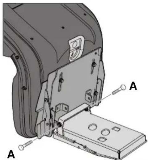
5.2.3 Seat assembly (5) (Mod. 340 IX)
- The seat is supplied already assembled on the support plate.
- Position the seat by aligning the holes in the seat plate with those on the bottom plate.
- Insert the screws (M8x40) in the holes on the seat bracket and in the holes on the seat plate.
- Screw the seat into place. Tightening torques 20 ± 25 Nm.

If the screws are tightened more than 25 Nm, the seat will be damaged.
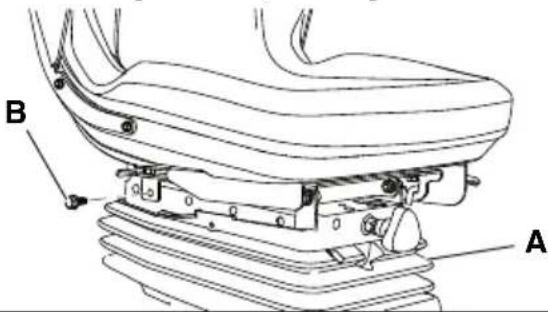
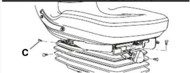
5.2.4 Bellows installation (7) (Mod. 740 IOX, 540 IX)
- Fasten the seat in place with the two screws (7:B).
- Position the bellows (7:A).
- Secure the bellows in place with the 10 pegs (7:C).
5.2.5 Install the carrier (8)
Install the carrier (8:B) on the back of the seat (8:A) using the 4 screws (8:C).
5.3 STEERING WHEEL (9)
- Push the steering wheel sleeve (9:A) all the way down the steering column (9:B).
- Align the holes on the sleeve with those on the steering column.
- Once the holes have been aligned (9:C), insert the two pins (9:D).
5.4 TOW BAR (10)
Install the tow bar (10:A) on the rear of the machine.
Use the screws and nuts (10:B; 10:C).
Tightening torque: 22 Nm.
5.5 QUICK-RELEASE SUPPORTS (1:P)
The quick-release supports and relative installation instructions are supplied in a separate box inside the machine packaging.
Install the quick-release supports on the machine's front axles.
5.6 BATTERY CHARGING

The battery must be fully charged before being used for the first time.

Please refer to 9.8 for the battery charging procedure.
5.7 TYRE PRESSURE
For the tyre pressure, please refer to "0 TECHNICAL DATA TABLE"
5.8 ACCESSORIES
For installation of accessories, see the installation guide accompanying each accessory.

For the application of the correct attachments, please contact the authorised service centre.

Note: In this case the cutting means assembly is considered an accessory..
6 COMMANDS AND CONTROL INSTRUMENTS
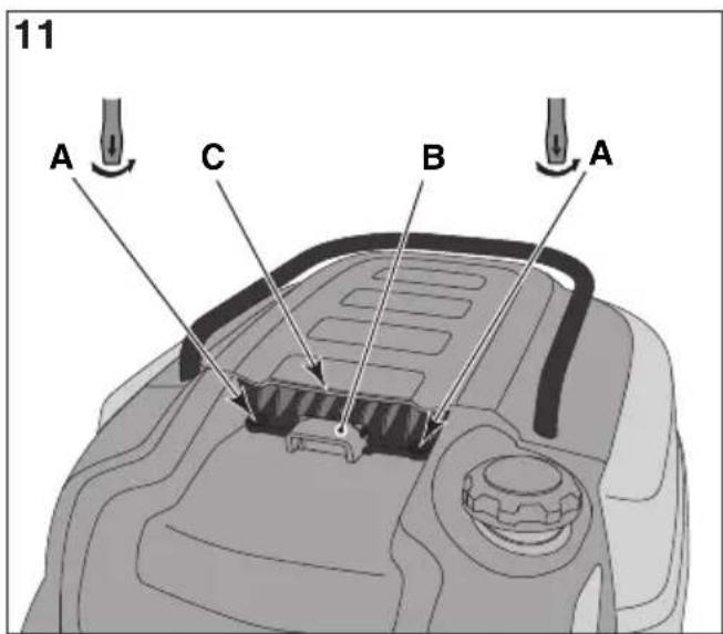
6.1 BONNET (11)
The bonnet can be opened as follows:
- Turn the two screws through 90° (11:A)
- Pull the handle up (11:B) while at the same time carefully lifting the bonnet (11:C).
- To close the bonnet, gently push down on it, if necessary, until the handle engages (11:B). Turn the two screws through 90° (11:A).

It is prohibited to start the engine when the bonnet is open.
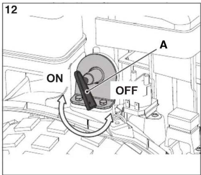
6.2 MAIN POWER KEY SWITCH (12)
The electrical power supply is activated by a key (12:A). This can be found under the bonnet (1:H) consequently to get to the main power switch you must first open the bonnet (see 6.1).
Insert the key (12:A) in the main power switch, push in and turn clockwise to switch on the electrical system's power supply.
Turn the key counter-clockwise to turn the power supply off.

The key can only be removed from the switch when it is turned counterclockwise.
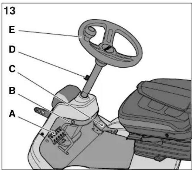
6.3 PARKING BRAKE PEDAL (13:A)

Never partially press the pedal while driving. There is a risk of overheating the power transmission.
The pedal (13:A) has the following three positions:
Released. Traction is engaged. The parking brake is not activated.
Pressed right down. Forward drive disengaged. The parking brake is fully activated but not locked. This poasition is also
used as an emergency brake.
The lever locks the “clutch-brake” pedal in the pressed right down position. This function is used to lock the machine on slopes, during transport, etc., when the engine is not running.
Locking:
- Press the pedal (13:A) right down.
- Pull the lever (13:B) up.
- Release the pedal (13:A).
- Release the lever (13:B).
Unlocking:
Press and release the pedal (13:A).
6.5 TRACTION PEDAL (13:C)
The pedal determines the gearing ratio between the engine and the drive wheels (= the speed).
When the pedal is released, the service brake is activated.

- Press the pedal forward – the machine moves forward.
- No load on the pedal – the machine is stationary.
- Press the pedal backward – the machine reverses.
Reduce the pressure on the pedal – the machine brakes.

If the machine does not brake as expected when the pedal is released, use the left pedal (13:A) as an emergency brake.
6.6 STEERING WHEEL (13:E)
The height of the steering wheel is fully adjustable. Unscrew the adjustment knob (12:E) on the steering column and raise or lower the steering wheel accordingly. Tighten.

Do not adjust the steering wheel when the machine is running.

Never turn the steering wheel when the machine is stationary with a lowered accessory. There is a risk of abnormal loads on the servo and steering mechanisms.
6.7 THROTTLE CONTROL (ACCELERATOR) (14:A)
Control for regulating engine running speed.

- Full throttle - should always be used when the machine is in use.

- Idling.
6.8 CHOKE CONTROL (14:B)
Used to turn on the engine when cold. The choke control has two positions:

-
Control completely pulled out - choke engaged. (for machine start in cold conditions).
-
Control pushed in - choke disengaged. (normal operation and warm start).

Do not use the choke when the engine is warm.
6.9 KEY SWITCH (14:C)

Key for enabling/inhibiting machine start-up.
Insert the key (14:C) and turn it to the "I" (START) position to enable machine start-up. All the indicators on the display and the acoustic signalling device are momentarily activated. Only the "hour meter" will remain active on the display together with the oil level warning light (which automatically turns itself off once the engine starts) and the parking brake indicator (if the parking brake is on) and the seat warning light if the driver is not seated.
Turn the key to the "O" position to inhibit machine start-up.

The key can only be removed when it is in the "O" position.

If the operator moves away from the machine and the key is in the “I” position, after 30 seconds a continuous acoustic warning sound is emitted. The acoustic warning signal persists until the operator returns to the machine or the machine is switched off.
6.10 CONSOLE DISPLAY AND MODE KEY (14:D; 15) (Mod. 740 IOX, 540 IX)

MODE key (14:E). With the MODE key it is possible to select the indicator lights corresponding to the functions: hour meter, ambient temperature, engine revs, battery. It is possible to force headlamp use by excluding the twilight sensor.
- Briefly press and release the key to access the display indicators corresponding to the various functions in succession. On the alphanumeric digits on the display the data associated with the selected icon is displayed, the last figure is reserved for the unit of measurement.
- Press for more than 1 second to turn on or off the headlamp.

Automatic headlamp control is automatically restored each time the machine is turned on.
Digits (15:A). Part of the display which provides alphanumerical data corresponding to the various functions.

Hours meter (15:B). The alphanumerical digits indicate the number of hours the machine has been driven, divided into hours and tenths of hours. It is active only when the engine is running. The unit of measurement is followed by the letter H.

Ambient temperature (15:C). The alpha-numerical digits indicate the ambient temperature. The unit of measurement is followed by the letter C.

Revs counter (15:D). The digits indicate the number of motor revs. When flashing it indicates the engine speed, with the PTO active, is not optimal (over 2500 rpm). Take the accelerator command to full throttle.

Service (15:E). Provides maintenance indications. The figures on the digits start flashing when the machine has reached the service time threshold.
Flashing will continue for two minutes and overrides the other functions on the display. In this phase the MODE key is disenabled.
When the hour meter reaches 99999 it returns to zero. After 999 hours, the minutes count is dropped.

Battery (15:F). The alphanumerical digits indicate battery voltage.

Power take-off (15:G). If the indicator light is on it means the PTO is active.

12V ON/OFF (15:H). If the indicator light is on it means the rear accessory is active.

Headlamp (15:1). If the indicator light is on it means that the headlamp, usually controlled by a twilight sensor, is switched on.

Maximum tilt (15:L). The indicator starts to flash if machine tilt exceeds the 10^ threshold.

In the event of sensor malfunction the message "TILT FAULT" appears.

Parking brake pedal (15:M). If the indicator light is on it means that the parking brake is on.

Seat (15:N). If the indicator light is on it means the driver is not seated.

Oil (15:P). If the indicator comes on while the machine is in operation it means the oil is low.
6.11 REAR ACCESSORY AND HEADLAMPS CONTROL (14:D; 15) (Mod. 340 IX)

Headlamps/12V button (14:E) Pressing the headlamp/12V button activates the functions to turn on the headlamp and activate the rear accessory.

When the command is enabled, the round LED around the button lights up.
- Quickly press and release to turn the headlamp on/off manually. If the control is enabled, the LED just above the button comes on.
- Press the button for more than 1 seconds to activate/deactivate the rear accessory. If the control is enabled, the LED just below the button comes on.
6.12 HOUR METER DISPLAY (14:D; 15) (Mod. 340 X)

Hour meter display (15:B). The alphanumeric digits indicate the number of hours the machine has been driven, divided into hours and tenths of hours. It is active only
when the engine is running. The unit of measurement is followed by the letter H.
When the hour meter reaches 9999 it returns to zero. After 999 hours, the minutes count is dropped.
6.13 POWER TAKE-OFF (14:F)

Button to engage / disengage the PTO (14:F). Press the button to engage / disengage the PTO.
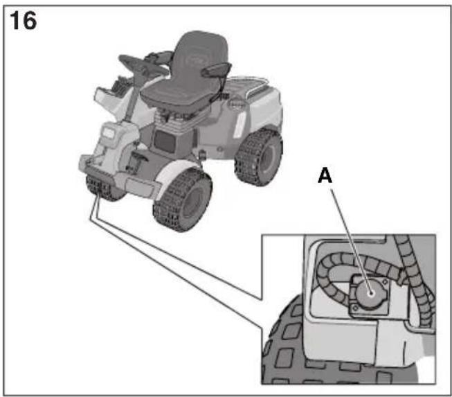
6.14 CUTTING HEIGHT ADJUSTMENT (14:G)
The machine has two buttons for adjusting the cutting height:

Press to raise the cutting height.

Press to lower the cutting height.
The cutting mean assembly is connected to the socket (16:A).
6.15 REAR ACCESSORY ADJUSTMENT CONTROL (14:H; 14:I)
The machine has a control for electrically adjusting the rear accessory (optional accessory).
The socket (17:B) (optional) for connecting the accessory is located on the back right-hand side of the machine.

The button can be used to lift and lower the rear accessory.

6.16 REAR ACCESSORY CONTROL (14:L)
The machine is designed for use with an electrical rear accessory.
The socket (17:A) for connecting the accessory is located on the back right-hand side of the machine.

Use this button to switch on/off the power supply to the accessory.
For the rear accessory power rating, please refer to "0 TECHNICAL DATA TABLE"

Only use accessories approved by STI-GA SpA.
6.17 ACCESSORY LIFTING DEVICE, HYDRAULIC (1:G)
The hydraulic accessories lifting device is active only when the engine is running and pedal (13:A) is released. The accessories lifting device is controlled by a lever (14:M).
The lever can be in one of the four following positions:

Floating positions. Move the lever to the most forward position, where it stops At this point the accessory is lowered to the floating position. In this position, it is always resting on the ground exerting the same pressure and can follow the profile of the terrain. Use the floating position when performing work.

Lowering. The accessory is lowered in a manner which does not depend on its weight.

Standby position (central). After lifting or lowering, the lever returns to the standby position. The accessory holds the position of the last command executed.

Lifting. Move the lever to the furthest back position until the accessory has reached the highest position (transport position). Then release the lever: the accessory remains blocked in the transport position.
6.18 HYDRAULIC CONNECTIONS CONTROL LEVER (14:O; 14:N) (Mod. 740 IOX)
The two levers (14:O; 14:N:) control the hydraulic connectors (18:A; 18:B) located on the back left-hand side of the machine.
To get to the connectors, remove the safety guard (18:C) secured in place with a screw.
Connect the accessories hydraulic lines to a pair of connectors AUX 1 or AUX2 (18).
Both levers have three positions:
Forward/Back: move the lever in either of these directions to move the connected accessory in the relative direction (please refer to the instructions supplied with the accessory).
Central position: standby.
To activate the accessory, proceed as follows:
- Move the lever forward / back just enough to obtain the required movement.
- Release the lever to lock the accessory in the selected position, the lever automatically returns to the standby position.
6.19 TRANSMISSION ENGAGE/DISENGAGE LEVER (19)
A lever for disengaging the variable transmission.

The engage / disengagelever must never be between the outer and inner positions. This overheats and damages the transmission.
The levers allow the user to move the machine manually (pushing or pulling), without the engine running. The two positions are:

-
Transmission disengaged = lever out. For normal use, locking of the lever in this position is confirmed by a click.
-
Transmission disengaged = transmission disengaged. The machine can be moved by hand.
The machine must not be towed over long distances or at high speeds. The transmission could be damaged.

Never activate the machine with the transmission disengaged (lever in). Risk of damage and oil leakage in the front axle.
6.20 SEAT ADJUSTMENT (20)
The seat can be moved backwards and forwards to suit the driver as indicated below:
- Move the control lever (20:A) upwards.
- Set the seat to the desired position.
- Release the control lever (20:A) to lock the seat. Using the relative knob (20:B) [740 IOX / 540 IX] it is also possible to adjust suspension rigidity.
- Turn the knob clockwise for tighter suspension.
- Turn the knob anticlockwise for slacker suspension.

Act on the knob until you reach the required level of comfort.
The seat is equipped with a safety switch that is connected to the machine's safety system. This means that when no-one is sitting in the seat the machine cannot be started (see 7.8.2).
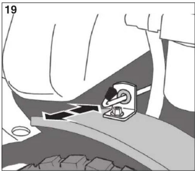
6.21 QUICK-RELEASE SUPPORTS (21; 22; 23)

These support allows the user to swap from one attachment to another quickly and easily.
The quick-release supports allow the user to move the cutting mean assembly quickly and easily between two positions, i.e.:
- Normal position with the belt fully tensioned.
- Positioned 4 cm behind the normal position,
with the belt slackened, so that the cutting mean assembly moves closer to the base of the machine.
Being as the belt tensioner is released from the belt, the quick-release supports simplify belt and cutting mean assembly replacement, and also make shifting to the washing position and service positions easier.
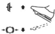
Belt tension releasing (21)

See also the instructions provided with the accessory and with the quick-release support.
- Remove the cotter pins or lock pins (21:C) from both sides.
- Open the quick-release supports by pressing on their rear sections with your heel (21:A).

Once the quick-release supports have been opened, the arms of the accessory are free and no longer secured to the hook-up device.

For any adjustment or maintenance operation, replace the arms on the support and reclose.
- Carry out the necessary corrective action, e.g.:
- Release the belt.
- Replace the accessory by unhooking the arms (22).
Tensioning the belt (21, 22)
First tension one side and then the other according to the instructions provided below.

Do not turn the lever using your hands. Risk of crushing injuries.
- Place your foot on the lever (22:A) and carefully turn it 180^ forwards.
- Install the cotter pin or lock pin (21:C).
- Repeat the operation on the other side.
7 START-UP AND OPERATION
7.1 PRECAUTIONS FOR USE

Always make sure the engine oil level is correct. This is particularly important when operating on slopes (see 7.66).
Apply the parking brake when you park the machine.

Do not turn the steering wheel to full lock when driving at full speed. The machine may overturn.

Keep hands and feet well away from the articulated steering joint and seat bracket. Risk of crushing injuries.
7.2 COMBINED USE OF ACCESSORIES

For the combined use of accessories, please refer to the "TABLE FOR THE CORRECT COMBINATION OF ACCESSORIES" in section "0 TECHNICAL DATA TABLE"
7.3 REFUELLING (24)

Always use lead-free petrol only. DO NOT mix petrol with oil.
For the capacity of the fuel tank, please refer to "0 TECHNICAL DATA TABLE". The transparency of the tank allows the user to check the level easily.

NOTE! Petrol is perishable and should not remain in the tank for more than 30 days.
It is possible to use ecological fuels, i.e. alkylate petrol. The composition of this petrol is less harmful to people and the environment.
No negative effects linked to use of the same have been reported. However, there are types of alkylate-based petrol available on the market for which it is not possible to give precise indications regarding their use. For further information it is advisable to consult the instructions and data provided by the producer of the alkylate-based petrol.
The transparency of the inspection glass (24:A) on the tank makes it easy to check the level. Never fill the tank right to the top. Leave a little space (equal to at least the whole depth of the top-up mouth + 1 - 2 cm from the top of the tank) so that when the petrol heats up it has room to expand without overflowing.

If you plan on putting the machine away for a prolonged period (e.g. over the winter), only put enough fuel in the tank to finish the last job in hand.
In fact, before storing the machine it is a good idea to empty the fuel tank completely (see 11).
7.4 BONNET (10)

For instructions on how to get to the engine and the key switch, please refer to section 6.1.
7.5 ENGINE CASING (30)
To remove the engine casing, you must first open the bonnet.
7.5.1 Engine casing removal
- Undo the 8 screws (30:A).
- Take the cap off the petrol tank.
- Remove the engine casing (30:B).
- Replace the cap on the petrol tank.
- Perform the necessary interventions.
7.5.2 Engine casing installation.
- Take the cap off the petrol tank again.
- Reposition the engine casing (30:B).
- Replace the cap on the petrol tank.
- Screw the 8 screws back in.
7.6 CHECKING THE ENGINE OIL LEVEL (25)
The machine is delivered complete with engine oil.

Before starting the machine check the level of the engine oil.

To check / top up the engine oil, see 99.5.1, 99.5.2.
7.7 CHECKING THE TRANSMISSION FLUID LEVEL

To check / top up the transmission fluid, see 99.6.1.
7.8 SAFETY CHECKS
When trying out the machine, check that the results of the safety checks correspond with the indications provided in the following tables.

Always carry out the safety checks before use.

If any of the results fails to match the indications provided in the following table, do not use the machine! Take it to a service centre to be checked and repaired if necessary.
7.8.1 General safety check
| Object Result | |
| Fuel lines and connections. | No leaks. |
| Electrical cables. All insulation intact.No mechanical damage. | |
| Exhaust system. No | leaks at connections. All screws tightened. |
| Oil lines No leaks. No damage. | |
| Activate the machine forwards/backwards and release the traction pedal. | The machine will stop. |
| Test driving No abnormal vibrations. No abnormal sound. | |
7.8.2 Electrical safety check
| Country/State Action Result | ||
| Driver not seated. Parking brake engaged. | Try to start the engine. | The engine does not start. On the display (if present) the message “SIT DOWN” appears. |
| Driver seated. Parking brake disengaged. | Try to start the engine. | The engine does not start. On the display (if present) the message “PRESS BRAKE” appears. |
| Driver seated. Parking brake engaged. | Try to start the engine. | The engine starts. |
| Engine on, cutting device disengaged, parking brake engaged. | The driver gets up from the seat. | The engine stays on. |
| Engine on, cutting device disengaged, parking brake disengaged. | The driver gets up from the seat. | The engine is switched off.. |
| Engine on, cutting device engaged, parking brake disengaged. | The driver gets up from the seat. | The engine is switched off.. |
| Engine on, cutting device disengaged, parking brake engaged. | The driver gets up from the seat. | The engine is switched off.. |
7.9 START-UP / OPERATION

When using the machine, the bonnet must be closed and fastened shut.

Always use full throttle when using the machine.
- Open the fuel cock (24:B).
- Insert the key in the main power switch (12:A).
- Engage the transmission (19) - (lever out).
- Insert the key in the switch (14:C).
- Do not keep your foot on the traction pedal (13:C).
Cold start
- Activate the parking brake (13:A).
- Turn the throttle to full on (14:A).
- Pull the choke out completely (14:B).
- Turn the switch key to the "I" position and press the START button (14:P).

Before starting work with the machine, wait a few minutes for the oil to warm up.

For use in low temperatures, warm the machine up to bring the hydraulic fluid and the transmission to the proper temperature. Otherwise the transmission could get damaged.
Warm start
- Activate the parking brake (13:A).
- Turn the throttle to full on (14:A).
- The choke control (14:B) needs to be lowered.
- Turn the switch key to the "I" position and press the START button.

To proceed see the instructions provided in headingparagrafo 7.9.1.
7.9.1 Operation
To operate with the machine proceed as described below:
- Press the pedal (13:A) right down then release it.
- Activate the pedal (13:C) to move the machine.
- Go to the work area.
- If front accessories have been installed, activate the PTO (14:F).
- Commence work.
7.10 STOPPING
To stop the machine, proceed as follows:
- Press the parking brake pedal (13:A).
- Pull the lever (13:B) up.
-
Release the pedal (13:A).
-
Leave the engine to idle for at least a minute or two.
- Press the STOP button (14:P) to turn the machine off.
- Turn the switch key (14:C) to the "0" position and pull it out.
- Close the fuel cock. This indication is particularly important if the machine is to be transported on a trailer or similar.
• Take the key out of the main power switch.

If you need to leave the machine unattended, remove the key from the switch (14:C) and the key from the main power switch (12:A).

The engine may be very hot just after it has been switched off. Do not touch the silencer, the engine or the cooling fins. Burns hazard.
7.11 CLEANING

Never use high-pressure water jets. This can damage shaft seals, electrical components or hydraulic valves.
Never use high-pressure water jets aimed directly at the radiator fins. This could damage the structure of the fins.
Always clean the machine after use. To clean the machine adhere to the instructions provided below:
- Do not spray water directly onto the engine.
- Clean the engine with a brush and/or compressed air.
- Clean the motor cooling air intake.
- After cleaning using water, start the machine and any cutting mean assembly to remove any water which may otherwise end up in the bearings and cause damage.
8 USING THE ATTACHMENT

Make sure the grass to be cut is completely free of foreign objects such as stones etc.
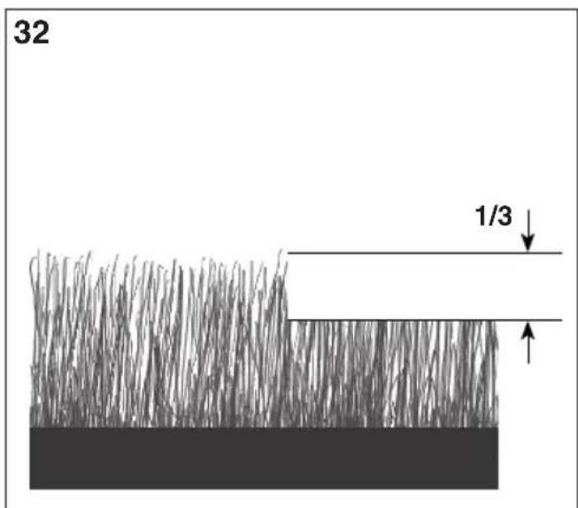
8.1 CUTTING HEIGHT
For best results, cut off the top third of the grass. See fig. 32.
If the grass is long and needs cutting back significantly, cut twice using two different cutting heights.
Do not use the lowest cutting heights if the lawn surface is uneven.
This would entail a risk of the cutting means being damaged against the surface and the lawn's top layer of soil being removed.
8.2 MOWING TIPS
To get the best mowing results, follow the tips given below.
- Cut grass frequently.
- Run the machine at full revs.
- Grass should not be wet.
- Only use sharp cutting means.
- Keep the bottom side of the cutting mean clean.
9 MAINTENANCE
9.1 ASSISTANCE PROGRAMME
To keep the machine in good condition as regards reliability, operational safety and attention to the environment, always comply with the STIGA SpA assistance programme.
Details on this programme's interventions are illustrated in the attached STIGA SpA maintenance manual.
The Basic Service must always be carried out by an authorized service workshop.
The First Service and Intermediate Service should be carried out by an authorized service workshop, but can also be carried out by the user. The procedures are indicated in the handbook and are described in the chapter “7 START-UP AND OPERATION” as well as here below.
The checks carried out by an authorized service workshop guarantee professional workmanship and the use of genuine spare parts.
The handbook is stamped every time a Basic Service is performed and each time an Intermediate Service is carried out by an authorized service workshop. A handbook with these stamps increases the second-hand value of the machine.
9.2 PREPARATION
All service and all maintenance checks must be carried out on a stationary machine with the engine switched off.

Always apply the parking brake to stop the machine from moving.
Turn off the engine.
Avoid inadvertent engine start-up by removing the key from the switch (14:C) and the key from the main power switch (12:A).

For the frequency of this intervention see chapter 13.
9.3 Maintenance table.

See chapter “13 MAINTENANCE SUMMARY TABLE”. The table is designed to help you keep your machine in efficient and safe working order. It indicates the main operations to be performed and the frequency of the same. Perform the relative operation described based on the first deadline to arrive.
9.4 TYRE PRESSURE
Adjust the tyre pressure to meet the values provided in "0 TECHNICAL DATA TABLE".
9.5 CHECK/TOP UP ENGINE OIL

For this maintenance operation, see also the manual for the engine supplied with the machine.

Always check the oil level before use. To check the level, make sure the machine is on even ground.

The oil level must never exceed the "FULL" mark. This results in the engine overheating. If the oil level exceeds the "FULL" mark, the oil must be drained until the correct level is achieved.

Change the oil more frequently if the engine has to operate in demanding conditions or if the ambient temperature is high.
9.5.1 Check / top-up (26) (Mod. Honda GXV 630; 660; 690)

Wipe around the dipstick. Unscrew it and pull it out. Wipe the dipstick clean.
Insert the dipstick completely without screwing it in place.
Now pull the dipstick up again. Read off the oil level.
Top up if the level is lower than the "FULL" mark (26).
9.5.2 Check / top-up (29; 27) (Mod. B&S 8270; B&S VANGUARD 18HP)

Wipe around the dipstick. Unscrew it and pull it out. Wipe the dipstick clean.
Push the dipstick down completely and screw in place.
Now unscrew and pull the dipstick up again. Read off the oil level.
Top up if the level is lower than the "FULL" mark (29; 27).
9.6 CHECKING/TOP-UP THE TRANSMISSION FLUID
For the type of oil to use please refer to "0 TECH-NICAL DATA TABLE".
9.6.1 Check / top-up (25)
- Place the machine on a flat surface.
- Read the fluid level in the reservoir (25:A). The level should match the line.
- Top up if necessary.
9.7 BELT DRIVES
check that all the belts are intact.
9.8 BATTERY
For the type of battery installed on the machine, please refer to "0 TECHNICAL DATA TABLE"

WARNING! Battery acid is corrosive and contact with it is harmful. Handle the battery with care taking care not to let acid leak out.

Acid can cause serious injuries if it comes into contact with eyes or skin. If any part of the body comes into contact with acid, rinse immediately with copious amounts of water and seek medical attention immediately.
The battery fluid does not need checking or topping up. The only maintenance operation required is charging, for example after extended storage.
The battery can be charged:
- by the engine;
- by a battery charger.
9.8.1 Charging by the engine
This method is only an option if there is still enough charge in the battery to be able to start the engine.
- If the battery is new, connect the relative leads.
• Take the machine outside. - Start the engine by following the instructions provided in this manual.
- Leave the engine running continuously for 45 minutes (the time needed to fully charge the battery).
- Turn off the engine.
9.8.2 Charging with a battery charger

Use a constant voltage battery charger. Use of a standard charger may damage the battery. For further information, please contact your dealer.

Before connecting the battery charger, disconnect the battery from the electrical system.
9.8.3 Disassembly/assembly
The battery is located under the housing cover (30:C).
To get to the battery, proceed as follows:
- Close the fuel cock (24:B).
- Take the key out of the main power switch (see 6.2).
- Remove the 3 screws (31:A).
- Remove the battery cover (31:B) by lifting it upwards.
- Remove the battery holder (31:D) by undoing the two screws (31:E).
- Partially extract the battery (31:C) from its seat.
- Disconnect the black cable (=negative).
- Disconnect the red cable (=positive).
- Replace the dead battery.
- Connect the red cable to the battery's positive terminal (+).
- Push the new battery into its seat.

Warning: when pushing the battery in, accompany the red cable to make sure it doesn't get trapped: this would prevent correct positioning of the battery in its seat.
- Connect the black cable to the battery's negative terminal (-).
- Reposition the battery holder by tightening the two screws (31:E).
- Reposition the battery cover (31:B).
- Screw the 3 screws back in (31:A).
- Insert the key in the main power switch (only if you intend to use the machine).
- Open the fuel cock (only if you intend to use the machine).

If the leads are disconnected/connected in the wrong order, there is a risk of a short-circuit and damage to the battery.
If the leads are interchanged, the alternator and the battery may be damaged.
Tighten the leads securely. Loose leads are a fire risk.
Never start the engine with the battery disconnected. There is a risk of serious damage to the alternator and the electrical system.
9.8.4 Cleaning
If the battery terminals are coated with oxide, they should be cleaned. Clean the battery terminals with a wire brush and lubricate them with terminal grease.
9.9 AIR FILTER, ENGINE

For this maintenance operation, see also the manual for the engine supplied with the machine.

NOTE! The filters should be cleaned/replaced more often if the machine operates on very dusty ground. Remove/install the air filters as follows:
9.9.1 Air filter (Mod. Honda GXV 630; 660; 690) (26)
- Clean carefully around the air filter housing.
- Remove the air filter cover (26:D) by releasing the two lateral tabs.
- Dismantle the pre-filter assembly (26:C). Remove the paper filter (26:B). Make sure that no dirt gets into the carburettor. Clean the air filter housing.
- Clean the paper filter by tapping it gently against a flat surface. If the filter is very dirty, replace it.
- Assemble the filter by performing the above instructions in reverse order.
Compressed air or petroleum-based solvents such as kerosene must not be used for cleaning the paper filter insert. This will damage the filter.
Do not use compressed air for cleaning the paper filter insert. The paper filter insert must not be oiled.
9.9.2 Air filter (Mod. B&S 8270) (29X)
- Carefully clean around the air filter cover.
- Remove the air filter cover (29X:A) by un-screwing the two knobs (29X:B).
- Dismantle the filter assembly (29X:C). Extract the pre-filter (29X:D).
- Clean the paper filter by tapping it gently against a flat surface. If the filter is very dirty, replace it.
- Clean the pre-filter. If the filter is very dirty, replace it.
- Assemble the filter by performing the above instructions in reverse order.
9.9.3 Air filter (Mod. B&S VANGUARD 18HP) (27X)
- Carefully clean around the air filter cover.
- Remove the air filter cover (27X:A) by removing the two clamps.
- Dismantle the filter assembly (27X:B). The prefilter is placed over the air filter. Make sure that no dirt gets into the carburettor. Clean the air filter housing.
- Clean the paper filter by tapping it gently against a flat surface. If the filter is very dirty, replace it.
- Clean the pre-filter. If the filter is very dirty, replace it.
- Assemble the filter by performing the above instructions in reverse order.
9.9.4 Spark plug
Before removing the spark plug, clean around its mounting.
For the type of spark plug and relative spark gap, please refer to "0 TECHNICAL DATA TABLE".
9.9.5 Air intake
See figure (26:A, 27:C,29X:E). The engine is air-cooled. A blocked cooling system can damage the engine. Clean the motor air intake. More meticulous cleaning of the cooling system should be carried out during each basic service.
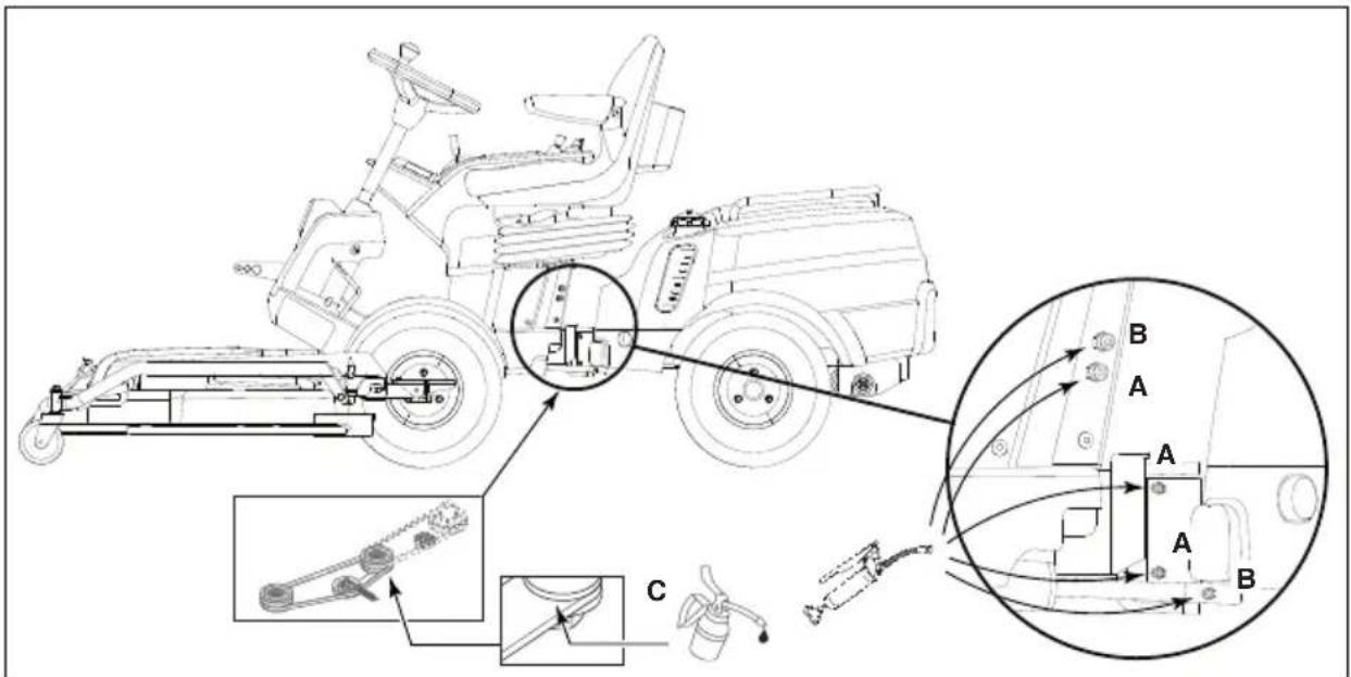
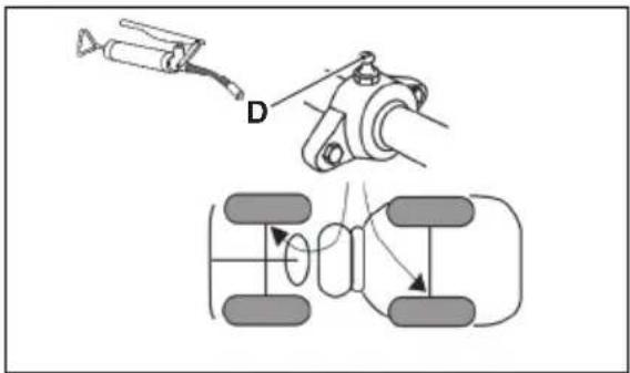
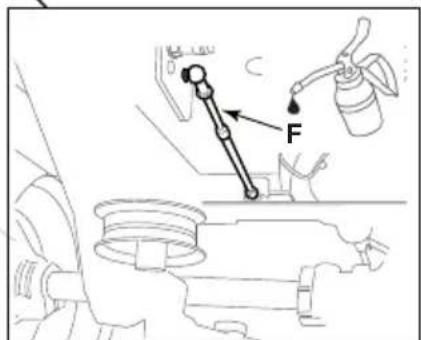
9.10 LUBRICATION (28)
| Object Action Fig. | ||
| Centre point | 3 grease nipples located on the central articulation on the left-hand side of the machine. Use a grease gun filled with universal grease. Pump until the grease seeps out. | 28:A |
| Steering wheel | 2 grease nipples located on the central articulation on the left-hand side of the machine. Use a grease gun filled with universal grease. Pump until the grease seeps out. | 28:B |
| Tensioning arms | Lubricate the support points of the tensioning arms with oil. | 28:C |
| Wheel bearings | 2 grease nipples. Use a grease gun filled with universal grease. Pump until the grease seeps out. | 28:D |
| Quick-release supports | 1 grease nipple for each front wheel. Use a grease gun filled with universal grease. Pump until the grease seeps out. | 28:E |
| Control cables | Lubricate the control cable ends with oil. | 28:F |
9.10.1 Fuses (31:F)
| Destination Fuse | |
| Electrical system power supply 20 A | |
| Battery charger power supply. 25 A |
To replace the fuses, proceed as follows:
- Close the fuel cock (24:B).
- Open the bonnet (see 7.4).
- Take the key out of the main power switch (see 6.2).
- Remove the engine casing (see 7.5.1).
- Replace the damaged fuse.
- Replace the engine caring (see 7.5.2).
- Insert the key in the main power switch (only if you intend to use the machine).
- Close the bonnet.
- Open the fuel cock (only if you intend to use the machine).
10 ASSISTANCE AND REPAIRS
This manual provides all the necessary information to run the machine and for correct basic maintenance operations which can be performed by the user. Any regulations and maintenance operations not described herein must be carried out by your Dealer or Authorized Service Centre, which have the necessary knowledge and equipment to ensure that the work is carried out correctly, maintaining the correct degree of safety and the original operating conditions of the machine.

Before performing any servicing operations:
a. Place the machine on a flat surface.
b. Apply the parking brake.
c. Turn off the engine.
d. Remove the key from the switch (14:C).
e. Remove the key from the main power switch (12:A).
Authorized service workshops carry out guaranteed repairs and maintenance. Always use genuine spare parts.

Genuine STIGA SpA spare parts and accessories were designed specifically for STIGA SpA machines. Please remember that non-genuine spare parts and accessories have not been verified or approved by STIGA SpA.

Use of non-genuine spare parts and accessories could have negative effects on the operation and safety of the machine. STIGA SpA shall decline all liability in the event of injuries or damages caused by such parts.
Genuine spare parts are supplied by authorized assistance workshops and dealers.

It is advisable to send your machine once a year to an authorized service workshop for servicing, assistance and safety device inspection.
11 STORAGE
- Empty the fuel tank:
- Start the machine's engine and leave it running until it stops.
- Thoroughly clean the whole machine. It is particularly important to clean the bottom side of the cutting mean assembly.
- If the paintwork is damaged, touch it up to prevent rust.
- Place the machine in a covered, dry place.

Charge the battery before putting the machine into storage. The battery can be seriously damaged it if is put into storage flat.
12 TERMS OF PURCHASE
The warranty covers all material and manufacturing defects. The user must follow all the instructions provided in the accompanying documentation.
The warranty does not cover damages caused by:
- failure to become familiar with the documentation accompanying the machine.
- carelessness.
- incorrect or prohibited use or assembly.
- use of non-genuine spare parts.
- use of accessories not supplied or approved by STIGA SpA.
The warranty does not cover:
- normal wear and tear of consumables, such as drive belts, headlights, wheels, bolts and wires.
• normal wear and tear
• engines. Engines are covered by the warranty provided by the relative manufacturer in compliance with the specified terms and conditions.
The purchaser is protected by his own national legislation. The purchaser's rights envisaged by the national laws in his own country are not in any way restricted by this warranty.
13 MAINTENANCE SUMMARY TABLE
| Intervention | Frequency service hours/calendar months | Ref. heading | |
| First time Then every | |||
| MACHINE | |||
| Check all fasteners - Before each use - | |||
| Safety checks/check controls - Before each use - | |||
| Check tyre pressure - Before each use - | |||
| General cleaning and inspection - At the end of each use - | |||
| General lubrication - 50 hours and after each wash | 9.10 | ||
| Check the drive belts for wear | 5 hours | 50 hours | 9.7 |
| Battery charging | - Before putting into storage | 9.8; 11 | |
| Cleaning the battery terminals | 5 hours | 100 hours | 9.8.4 |
| ENGINES/TRANSMISSION (general) | |||
| Check/top up transmission fluid | - | 50 hours | 9.6 |
| Replace fuel filter | - | Every season | *** |
| Change transmission fluid | 5 hours | 200 hours | *** |
| Replace transmission fluid reservoir filter | 5 hours | 200 hours | *** |
| Replacement / transmission oil filler | 50 hours | 200 hours | *** |
| Engine model Honda GXV 630; 660; 690 | |||
| Check/top up engine oil | - | Before each use | 99.5.1 |
| Change engine oil | 20 hours / 1 month | 100 hours / 6 months | *** |
| Replace the engine oil filter | - | 200 hours | *** |
| Clean/replace the paper filter | Check before each use | Clean every 100 hours / 6 months (intervene more often when using the machine in dusty areas). Replace every 500 hours / 2 years (filtering element only). | 9.9.1 |
| Replace the spark plug | 200 hours | - | |
| Clean the engine air intake | 50 hours | - | |
| Engine model B&S 8270 | |||
| Check/top up engine oil | - | Before each use | 9.5.2 |
| Change the engine oil | - | 50 - 100 hours / every season | *** (1) |
| Replace the engine oil filter | - | 50 - 100 hours / every season | *** (1) |
| Clean/replace the air pre-filter | 25 hours | 9.9.2 (2) | |
| Clean/replace the air filter | - | 100 hours / every season | 9.9.2 (2) |
| Replace the spark plug | Every season | - | |
| Clean the engine air intake | 8 hours / every day | - | |
| Engine model B&S Vanguard 18 HP | |||
| Check/top up engine oil | - | Before each use | 9.5.2 |
| Change the engine oil | 5 hours | 100 hours / every season | *** (1) |
| Replace the engine oil filter | - | 100 hours / every oil change | *** (1) |
| Replace the air pre-filter | 25 hours | 9.9.3 (2) | |
| Clean the air filter | - | 100 hours | 9.9.3 (2) |
| Replacing the air filter | 400 hours / every season | ||
| Replacing the spark plugs 100 hours / every season | |||
| Clean the engine air intak 8 hours / every season | |||
| *** Interventions which must be carried out by your dealer or an authorised assistance centre(1) 50 hours for original black B&S filters - 100 hours for high efficiency yellow B&S filters.(2) Clean more frequently when operating in particularly demanding conditions or when there is debris in the air. | |||
14 INFORMATION DISPLAY MESSAGES (Mod. 740IOX; 540IX)
MESSAGE ACTION / POSSIBLE CAUSE REMEDY
| CHECK CONNECTION An attempt has been made to start therear accessory (14:L). No accessory is connected to the socket (17:A). | Connect the plug on the accessory to the socket on the machine. |
| The plug is connected to the socket but the message persists. | Contact an authorised assistance centre. |
| NO MOVING An attempt has been made to adjustthe rear accessory (14:I; 14:H). No accessory connected to the socket (17:B). | Connect the plug on the accessory to the socket on the machine. |
| The plug is connected to the socket but the message persists. | Contact an authorised assistance centre. |
| START ENGINE | An attempt has been made to engage the PTO with the engine switched off. |
| PRESS BRAKE An attempt has been made to startthe engine with the parking brake off. | Put the parking brake on. |
| SIT DOWN An attempt has been made to start theengine with no-one in the driver's seat. | Sit in the driver's seat. |
| TILT FAULT | Tilt sensor malfunction.This text runs twice:- when the clinometer fails.- each time the machine is started up,after the initial indicator check runs on the display |
15 TROUBLESHOOTING
| PROBLEM PROBABLE CAUSE REMEDY | ||
| 1. The console does not come on. | Main power key switch set to “O”. | Turn the main power key switch to “I” |
| 2. The console does not come on.When the main power switch and the key switch are both turned to “I” the console remains switched off. | Turn the key switch and the main power switch to “O” and: | |
| Battery not connected. | Check the battery connections. | |
| Battery completely flat. Recharge the flat battery. | ||
| Fuse (20A) blown. Replace the fuse. | ||
| 3. The starter motor does not turn.With the key switch turned to “I” the display comes on but when the “START/STOP ENGINE” button is pressed the starter motor does not turn. | Battery not charged enough. Recharge the flat battery. | |
| 4. The starter motor turns but the engine does not start.With the key switch turned to “I” the display comes on but when the “START/STOP ENGINE” button is pressed the starter motor turns but the engine does not start. | Fuel cock closed. Open the fuel cock. | |
| No fuel flow. | - Check the fuel level in the tank.- Check the fuel filter. | |
| Ignition fault. | - Check the spark plug cap is securely in place.- Check the spark gap and that the electrodes are clean. | |
| 5. The battery indicator and digits flash.(740 IOX, 540 IX).The message “BATT”. appears. (340 IX) (340 IX)When attempting to start the machine, the machine does not start, the “Battery” indicator and the text on the digits starts to flash indicating that the voltage is lower than 12V. | Battery not charged enough. Charge the battery. | |
| Recharging fuse (25A) blown. Replace the fuse. | ||
| Faulty battery. Replace the battery. | ||
| 6. The battery indicator and digits flash. (740 IOX, 540 IX).The message “BATT”. appears. (340 IX) (340 IX).The “Battery” indicator and the text on the digits start to flash indicating a voltage over 12V. | The text on the digits indicates a voltage over 12V; there is an overvoltage. | Contact an authorised assistance centre. |
| 7. The battery indicator and digits flash and then the engine dies. (740 IOX, 540 IX). The message “BATT”. appears. (340 IX).The “Battery” indicator and the text on the digits start to flash indicating a voltage over 12V then the machine turns itself off. | The battery has exceeded the over-voltage threshold. | Contact an authorised assistance centre. |
| 8. The engine is running, the “Battery” indicator and the text on the digits flashes indicating a voltage below 12V. Compare la scritta “BATT”. (340 IX) | If the condition persists: | |
| Charge fuse (25A) blown. Replace the fuse. | ||
| Faulty battery. Replace the battery. | ||
| Faulty battery charger. Contact an authorised assistance centre. | ||
| 9. Difficulty in engine start-up or engine runs irregularly. | Carburetion problems. Clean or replace the air filter. | |
| 10. Drop in engine performance during cutting. | Forward speed too high in relation to the cutting height. | Reduce the forward speed and/or raise the cutting height. |
| 11. The battery indicator does not go off after a few minutes of operation. (740 IOX, 540 IX) | Insufficient recharge. Contact an authorised assistance centre. | |
| 12. The oil indicator comes on during operation. (740 IOX, 540 IX) | Engine lubrication problems. | - Turn the machine off immediately.- Top up the oil level (if the problem persists, contact an authorised assistance centre). |
| 13. The engine stops for no apparent reason. | - Fuel tank empty.- Try to restart the engine. | Fill the fuel tank (if the problem persists, contact an authorised assistance centre). |
| 14. Uneven cutting. Check the tyre pressure | ||
| The cutting mean sharpness level is low. | Contact an authorised assistance centre. | |
| Forward speed too high in relation to the height of the grass being cut. | Reduce the forward speed and/or raise the cutting height. | |
| The cutting means assembly is full of grass. | - Wait for the grass to dry.- Clean the cutting means assembly. | |
| 15. Abnormal vibration during use. | - Unbalanced cutting means.- Loose cutting means.- Loose components.- Possible damage. | Contact an authorised assistance centre for inspection, replacement or repair operations. |
| 16. With the engine running, activation of the traction pedal does not move the machine. | “Disengage transmission” lever in the disengaged position. | Engage the transmission. |
If problems persist after the operations above have been performed, contact your dealer.

Warning! Never attempt to carry out complicated repairs without the necessary tools or technical ability. Any poorly performed interventions will automatically nullify the warranty and exonerate the manufacturer from all liability.
Índice
0 TABLA DE DATOS TÉCNICOS ..... XI
1 INTRODUCCIÓN. 4
1.1 ESTRUCTURA DEL MANUAL
6.5 VEOPEDAAL (13:C)
9.9.5 Ilmanotto....22
9.10 VOITELU (28) 22
9.10.1 Sulakkeet(31:F). 22
10 HUOLTO JA KORJAUSTOIMENPITEET . . . . . . . . . . . . . . . . . . . . . . . . . . . . . . . . . . . . . . 22
11 VARASTOINTI. . . . . . . . . . . . . . . . . . . . . . . . . . . . . . . . . . . . . . . . . . . . . . . . . . . 23
12 OSTOEHDOT 23
13 HUOLTOTOIMENIPITEIDEN YHTEENVETOTAULUKKO 23
14 NÄYTÖN TIEDOTUSVIESTIT (MOD. 740IOX; 540IX) ..... 25
15 OPAS HÄIRIÖIDEN TUNNISTAMISEEN . . . . . . . . . . . . . . . . . . . . . . . . . . . . . . . . . . . . . . . . . . . 25
1 JOHDANTO

9.9 ILMANSUODATIN, MOOTTORI

1.1 STRUCTURE DU MANUEL
1.3 CONSERVATION DU MANUEL
12 CONDITIONS D'ACHAT
MESSAGE ACTION / CAUSE POSSIBLE REMÈDE
9.9.3 Čišćenje / Zamjena (Mod. B&S VAN-GUARD 18HP) (27X)
5.3 KORMÁNYKERÉK (9)
6.6 KORMÁNYKERÉK (13:E)
6.5 DARBINIS STABDYS-SANKABA (13:C)
6.5 PIEDZINAS PEDALIS (13:C)
9.1 APKOPES PROGRAMMA
10 ASSISTENTIE EN REPARATIES. 25
11 OPBERGEN 26
12 KOOPVOORWAARDEN 26
13 OVERZICHTSTABEL ONDERHOUDSWERKZAAMHEDEN ..... 27
14 MELDINGEN OP HET DISPLAY [MOD. 740IOX; 540IX] 28
15 GIDS VOOR HET OPSPOREN VAN STORINGEN . . . . . . . . . . . . . . . . . . . . 29
1 INLEIDING

7 START OG KJ∅RING....16
7.1 FORHOLDSREGLER VED BRUK....16
7.2 FYLLE DRIVSTOFFTANKEN (24) 16
7.3 KOMBINERT BRUK AV TILBEH∅R 17
7.4 MOTORPANSER (10) 17
7.5 VEIVHUS (30) 17
7.5.1 Demontere veivhuset 17
7.5.2 Montere veivhuset. 17
7.6 KONTROLL AV MOTOROLJENIVÅET (25)....17
7.7 KONTROLL AV OIJENIVÅET I GIRKASSEN . . . . . . . . . . . . . . . . . . . . . . . . . . . 17
7.8 SIKKERHETSKONTROLL 17
7.8.1 Generell sikkerhetskontroll 17
7.8.2 Sikkerhetskontroll av det elektriske anlegget 17
7.9 START/ARBEID 18
7.9.1 Kjøring. 18
7.10 STOPP 18
7.11 RENGJ∅RING 19
8 BRUK AV TILBEH∅RET 19
8.1 KLIPPEH∅YDE....19
8.2 KLIPPERÅD 19
9 VEDLIKEHOLD 19
9.1 SERVICEPROGRAM 19
9.2 KLARGJ∅RING. 19
9.3 Vedlikeholdstabell 19
9.4 DEKKTRYKK....20
9.5 KONTROLL/ETTERFYLLING AV MOTOROLJE 20
9.5.1 Kontroll/etterfylling (26) (Mod. Honda GXV 630; 660; 690). 20
9.5.2 Kontroll / etterfylling (29; 27) (Mod. B&S 8270; B&S VANGUARD 18HP). . . . . . . . . . . 20
9.6 KONTROLL/ETTERFyllING AV TRANSMISJONSOLJE 20
9.6.1 Kontroll/etterfylling (25). 20
9.7 REMDRIFT....20
9.8 BATTERI....20
9.8.1 Lading med motoren. 20
9.8.2 Lading med batterilader 20
9.8.3 Demontering/montering 21
9.8.4 Rengjøring 21
9.9 LUFTFILTER, MOTOR....21
9.9.1 Luftfilter (Mod. Honda GXV 630; 660; 690) (26) 21
9.9.2 Luftfilter (Mod.B&S 8270) (29X) 21
9.9.3 Luftfilter (Mod. B&S VANGUARD 18HP) (27X). 21
9.9.4 Tennplugg 22
9.9.5 Luftinntak 22
13 OVERSIKTSTABELL OVER VEDLIKEHOLD 24
14 INFORMASJONSMELDINGER PÅ DISPLAYET (MOD. 740IOX; 540IX) .....25
15 FEILS∅KINGSVEILEDNING . . . . . . . . . . . . . . . . . . . . . . . . . . . . . . . . . . . . . . . . . . . 26
1 INTRODUKSJON

2 BLI KJENT MED MASKINEN
3.4 VEDLIKEHOLD OG LAGRING

6.5 FREMDRIFTSPEDAL (13:C)
6.19 SPAK FOR INN-/UTKOBLING AV TRANSMISJONEN (19)
Spak som kobler ut den trinnløse transmisjonen.

6.20 SETEINNSTILLING (20)
13 OVERSIKTSTABELL OVER VEDLIKEHOLD
5.8 WYPOSAŻENIE DODATKOWE
6.2 GŁÓWNY WYŁĄCZNIK KLUCZOWY (12)
6.5 PEDAL NAPEDOWY (13:C)
Use os parafusos e as porcas (10:B; 10:C).
1.1 STRUCTURA MANUALULUI
1.3 PĂSTRAREA MANUALULUI
1.1 ŠTRUKTÚRA MANUÁLU 4
1.2 SYMBOLY POUŽITÉ V MANUÁLI 4
1.3 UCHOVÁVANIE MANUÁLU 4
2 ZOZNÁMENIE SA SO STROJOM. 4
2.1 CHARAKTERISTIKY STROJA 4
2.2 PREDPOKLADANÉ POUŽITIE 4
2.2.1 DEFINÍCIA POUŽÍVATEĽA . . . . . . . . . . . . . . . . . . . . . . . . . . . . . . . . . . . . . . . . . . . . . . 5
2.3 prepravovat' na stroji alebo na prívese iné osoby, hlavne deti alebo zvieratá; . . . . . . . 5
2.4 BEZPEČNOSTNÉ NÁVESTIA 5
2.5 IDENTIFIKAČNÝ ŠTÍTOK VÝROBKU 6
2.6 HLAVNÉ KOMPONENTY 6
3 BEZPEČNOSTNÉ PREDPISY 6
3.1 VÝCVIK 6
3.2 POČIATOČNĚ ŠKONY 7
3.3 PRI POUŽITÍ 8
3.4 ÚDRŽBA A SKLADOVANIE 10
3.5 PREPRAVA 11
3.6 OCHRANA ŽIVOTNÉHO PROSTREDIA 11
4 KOSAČKU SI POISTITE. 11
5 MONTÁŽ 11
5.1 KOMPONENTY PRE MONTÁŽ (3) 11
5.2 SEDADLO 12
5.2.1 Montáž opierok rúk (6) 12
5.2.2 Montáž sedadla (5) (Mod. 740 IOX, 540 IX) . . . . . . . . . . . . . . . . . . . . . . . . . . . . . . . 12
5.2.3 Montáž sedadla (5) (Mod. 340 IX) ..... 12
5.2.4 Montáž dúchadla (7) (Mod. 740 IOX, 540 IX) ..... 12
5.2.5 Montáž nosiča predmetov (8) 12
5.3 VOLANT (9) 12
5.4 TÄZNÁ TYČ (10) 13
5.5 RÝCHLOUPÍNACIE PRÍPOJKY (1:P)....13
5.6 DOBÍJANIE AKUMULÁTORA. 13
5.7 TLAK V PNEUMATIKÁCH 13
5.8 PRÍDAVNÉ ZARIADENIA 13
6 OVLÁDACIE PRVKY A KONTROLNÉ NÁSTROJE ..... 13
6.1 MOTOROVÁ SKRIŇA 13
6.2 HLAVNÝ ÚSEKOVÝ SPÍNAČ NA KL'UČ (12) 13
6.3 PEDÁL PARKOVACEJ BRZDY (13:A) 13
6.4 BLOKOVACIA PÁKA PARKOVACEJ BRZDY (13:B) 13
6.5 PEDÁL NÁHONU (13:C) 13
6.6 VOLANT (13:E) 14
6.7 OVLÁDAČ PLYNU (AKCELERÁTOR) (14:A) 14
6.8 OVLÁDANIE SÝTIČA (14:B) 14
6.9 KOMUTÁTOR NA KL'ÚČ (14:C). 14
6.10 DISPLEJ A E TLAČIDLO KONZOLY MODE (14:D; 15) (Mod. 740 IOX, 540 IX) ..... 14
6.11 OVLÁDANIE SVETLOMETOV A ZADNÉHO SVIETIDLA (14:D; 15) (Mod. 340 IX) . . . . . 15
6.12 DISPLEJ POČÍTADLO MOTOHODÍN (14:D; 15) (Mod. 340 X). ..... 15
6.13 POHON PRÍSLUŠENSTVA (14:F): 15
6.14 NASTAVOVANIE VÝŠKY KOSENIA (14:G) 15
6.15 OVLÁDAČ NASTAVOVANIA ZADNÉHO NÁSTROJA (14:H; 14:I) ..... 15
6.16 OVLÁDAČ ZADNÉHO NÁSTROJA (14:L) 16
6.17 HYDRAULICKY ZDVÍHAČ PRÍDAVNÝCH ZARIADENÍ (1:G) 16
6.18 OVLÁDACIE PÁKY POMOCNÝCH HYDRAULICKÝCH ČEL'USTÍ (14:O; 14:N) (Mod. 740 IOX)
16
6.19 PÁKA ZARADENIA / ODISTENIA POHONU (19). 16
6.20 NASTAVENIE SEDADLA (20) 17
6.21 RÝCHLOUPÍNACIE PRÍPOJKY 17
7 SPUSTENIE A PREVÁDZKA. 17
7.1 OCHRANNÉ OPATRENIA PRI PREVÁDZKE 17
7.2 KOMBINOVANÉ POUŽITIE NÁSTROJOV 18
7.3 TANKOVANIE (24) 18
7.4 MOTOROVÁ SKRIŇA (10) 18
7.5 OCHRANNÝ KRYT (30) 18
7.5.1 Demontáž ochranného krytu. 18
7.5.2 Montáž ochranného krytu. 18
7.6 KONTROLA HLADINY OLEJA V MOTORE (25)....18
7.7 KONTROLA HLADINY OLEJA V PREVODOVKE 18
7.8 KONTROLA BEZPEČNOSTI 18
7.8.1 Všeobecná bezpečnostná kontrola 18
7.8.2 Elektrická kontrola bezpečnosti 19
7.9 SPUSTENIE / PRÁCA 19
7.9.1 Prevádzka 19
7.10 ZASTAVENIE....20
7.11 ČISTENIE 20
8 POUŽITIE PRÍDAVNÉHO ZARIADENIA .....20
8.1 VÝŠKA KOSENIA....20
8.2 RADY PRE SPRÁVNE KOSENIE . . . . . . . . . . . . . . . . . . . . . . . . . . . . . . . 20
9 ÚDRŽBA 20
9.1 SERVISNÝ PROGRAM 20
9.2 PRÍPRAVA 21
9.3 TABUL'KA ÚDRŽBY 21
9.4 TLAK V PNEUMATIKÁCH 21
9.5 KONTROLA / DOPLNENIE MOTOROVÉHO OLEJA. 21
9.5.1 Kontrola / doplnenie (26) (Mod. Honda GXV 630; 660; 690) ..... 21
9.5.2 Kontrola / doplnenie (29; 27) (Mod. B&S 8270; B&S VANGUARD 18HP) ..... 21
9.6 KONTROLA / DOPLNENIE PREVODOVÉHO OLEJA 21
9.6.1 Kontrola / doplnenie (25) 21
9.7 REMEŇOVÉ POHONY 21
9.8 AKUMULÁTOR....22
9.8.1 Dobijanie cez motor . . . . . . . . . . . . . . . . . . . . . . . . . . . . . . . . . . 22
9.8.2 Dobijanie dobijačkou 22
9.8.3 Demontáz/montáz. 22
9.8.4 Čistenie 22
9.9 VZDUCHOVÝ FILTER, MOTOR. 23
9.9.1 Vzduchový filter (Mod. Honda GXV 630; 660; 690) (26) . . . . . . . . . . . . . . . . . . . . . . . . . . . . 23
9.9.2 Vzduchový filter (Mod. B&S 8270) (29X) . . . . . . . . . . . . . . . . . . . . . . . . . . . . . . . . . . 23
9.9.3 Vzduchový filter (Mod. B&S VANGUARD 18HP) (27X) . . . . . . . . . . . . . . . . . . . . . . 23
1.1 ŠTRUKTÚRA MANUÁLU
1.2 SYMBOLY POUŽITÉ V MANUÁLI

1.3 UCHOVÁVANIE MANUÁLU
Návod na prevádzku uchovávajte v dobrom a čitatel'nom stave, na známom mieste, ktoré je používatel'ovi stroja l'ahko dostupné.
2 ZOZNÁMENIE SA SO STROJOM
9.9.3 Zračni filter (Mod. B&S VANGUARD 18HP) (27X) 22
9.9.4 Zamenjava svečke 22
9.9.3 Zračni filter (Mod. B&S VANGUARD 18HP) (27X)

13 SAMMANFATTANDE TABELL FÖR UNDERHÅLL 24
14 INFOMEDDELANDEN PÅ SKÄRMEN (MOD. 740IOX; 540IX) . . . . . . . . . . . . . . . . 25
15 FELSÖKNINGSGUIDE. 26
1 INTRODUKTION

13 SAMMANFATTANDE TABELL FÖR UNDERHÅLL
D. Lgs. 262/2002, ANNEX VI, proc. 1 (Italy)
EN • The content and images in this User Manual were produced expressly for STIGA S.p.A. and are protected by copyright – any unauthorised reproduction or modification to the document, either partially or in full, is prohibited.