
WR 14VE - Electric drill HiKOKI - Free user manual and instructions
Find the device manual for free WR 14VE HiKOKI in PDF.

| Product type | Electric drill (impact wrench) |
| Brand | HiKOKI |
| Model | WR 14VE |
| Supply voltage | 110-240 V depending on region |
| Power consumption | 370 W |
| No-load speed (max) | 0 - 2100 min⁻¹ |
| Impact rate (max) | 0 - 2700 min⁻¹ |
| Max tightening torque | 250 N·m |
| Drilling capacity | M8-M14 (high-tensile bolts), M10-M18 (ordinary) |
| Weight | 2.1 kg (according to EPTA 01/2014) |
| Impact mode | 4 selectable modes (A, B, C, D) |
| Rotation direction | Forward and reverse (reversing switch) |
| Chuck type | Hexagonal or square socket |
| Protection functions | Overload, temperature, continuous operation protection, sensor |
| Power supply | Mains powered with power cord |
| Included accessories | Case, hook |
| Warranty | Manufacturer's warranty according to national regulations |
| Maintenance | Regular check of fasteners, cleaning, cord replacement by professional |
| Safety | Read warnings, wear PPE, disconnect before maintenance |
| General information | Manual provided, spare parts available at authorized service center |
Frequently Asked Questions - WR 14VE HiKOKI
User questions about WR 14VE HiKOKI
0 question about this device. Answer the ones you know or ask your own.
Ask a new question about this device
Download the instructions for your Electric drill in PDF format for free! Find your manual WR 14VE - HiKOKI and take your electronic device back in hand. On this page are published all the documents necessary for the use of your device. WR 14VE by HiKOKI.
USER MANUAL WR 14VE HiKOKI
natural_image
Line drawing of a handheld electric drill press with control panel and motor (no text or symbols)
en Handling instructions
de Bedienungsanleitung
fr Mode d'emploi
it Istruzioni per l'uso
nl Gebruiksaanwijzing
es Instrucciones de manejo
pt Instruções de uso
sv Bruksanvisning
da Brugsanvisning
no Bruksanvisning
fi Käyttöohjeet
el Οδηγίες χειρισμού
pl Instrukcja obsługi
hu Kezelési utasítás
cs Návod k obsluze
tr Kullanım talimatları
ro Instructiuni de utilizare
① Navodila za rokovanje
sk Pokyny na manipuláciu
bg Инструкция за експлоатация
sr Uputstvo za rukovanje
hr Upute za rukovanje

(Original instructions)
GENERAL POWER TOOL SAFETY WARNINGS

WARNING
Read all safety warnings, instructions, illustrations and specifications provided with this power tool.
Failure to follow all instructions listed below may electric shock, fire and/or serious injury.
Save all warnings and instructions for future reference.
The term "power tool" in the warnings refers to your mains-operated (corded) power tool or battery-operated (cordless) power tool.
1) Work area safety
a) Keep work area clean and well lit. Cluttered or dark areas invite accident
b) Do not operate power tools in explosive atmospheres, such as in the presence of flammable liquids, gases or dust.
Power tools create sparks which may ignite the dust or fumes.
c) Keep children and bystanders away while operating a power tool.
Distractions can cause you to lose control.
2) Electrical safety
a) Power tool plugs must match the outlet. Never modify the plug in any way. Do not use any adapter plugs with earthed (grounded) power tools.
Unmodified plugs and matching outlets will reduce risk of electric shock.
b) Avoid body contact with earthed or grounded surfaces, such as pipes, radiators, ranges and refrigerators.
There is an increased risk of electric shock body is earthed or grounded.
c) Do not expose power tools to rain or wet conditions.
Water entering a power tool will increase the risk of electric shock.
d) Do not abuse the cord. Never use the cord for carrying, pulling or unplugging the power tool.
Keep cord away from heat, oil, sharp edges or moving parts.
Damaged or entangled cords increase the risk electric shock.
e) When operating a power tool outdoors, use an extension cord suitable for outdoor use.
Use of a cord suitable for outdoor use reduces the risk of electric shock.
f) If operating a power tool in a damp location is unavoidable, use a residual current device (RCD) protected supply.
Use of an RCD reduces the risk of electric shock.
3) Personal safety
a) Stay alert, watch what you are doing and use common sense when operating a power tool. Do not use a power tool while you are tired or under the influence of drugs, alcohol or medication.
A moment of inattention while operating power tools may result in serious personal injury.
b) Use personal protective equipment. Always wear eye protection.
Protective equipment such as a dust mask, non-skid safety shoes, hard hat or hearing protection used for appropriate conditions will reduce personal injuries.
c) Prevent unintentional starting. Ensure the switch is in the off-position before connecting to power source and/or battery pack, picking up or carrying the tool.
Carrying power tools with your finger on the switch or energising power tools that have the switch invites accidents.
desh Remove any adjusting key or wrench before turning the power tool on.
A wrench or a key left attached to a rotating part of the power tool may result in personal injury.
e) Do not overreach. Keep proper footing and balance at all times.
This enables better control of the power tool unexpected situations.
f) Dress properly. Do not wear loose clothing or jewellery. Keep your hair and clothing away from moving parts.
Loose clothes, jewellery or long hair can be caught in moving parts.
g) If devices are provided for the connection of dust extraction and collection facilities, ensure these are connected and properly used.
Use of dust collection can reduce dust-related hazards.
h) Do not let familiarity gained from frequent use of tools allow you to become complacent and ignore tool safety principles.
A careless action can cause severe injury within fraction of a second.
4) Power tool use and care
a) Do not force the power tool. Use the correct power tool for your application.
The correct power tool will do the job better and safer at the rate for which it was designed.
b) Do not use the power tool if the switch does not if turn it on and off.
Any power tool that cannot be controlled with switch is dangerous and must be repaired.
c) Disconnect the plug from the power source and/or remove the battery pack, if detachable, from the power tool before making any adjustments, changing accessories, or storing power tools.
Such preventive safety measures reduce the risk of starting the power tool accidentally.
d) Store idle power tools out of the reach of children and do not allow persons unfamiliar with the power tool or these instructions to operate the power tool.
Power tools are dangerous in the hands of untrained users.
e) Maintain power tools and accessories. Check for misalignment or binding of moving parts, breakage of parts and any other condition that may affect the power tool's operation. If damaged, have the power tool repaired before use.
Many accidents are caused by poorly maintain power tools.
f) Keep cutting tools sharp and clean.
Properly maintained cutting tools with sharp cutting edges are less likely to bind and are easier to control.
g) Use the power tool, accessories and tool bits etc. in accordance with these instructions, taking into account the working conditions and the work to be performed.
Use of the power tool for operations different those intended could result in a hazardous situation.
h) Keep handles and grasping surfaces dry, clean and free from oil and grease.
Slippery handles and grasping surfaces do allow for safe handling and control of unexpected situations.
5) Service
a) Have your power tool serviced by a qualified repair person using only identical replacement parts.
This will ensure that the safety of the power tool is maintained.
PRECAUTION
Keep children and infirm persons away.
When not in use, tools should be stored out of reach of children and infirm persons.
IMPACT WRENCH SAFETY WARNINGS
○ Hold the power tool by insulated gripping surfaces, when performing an operation where the fastener may contact hidden wiring or its own cord.
Fasteners contacting a "live" wire may make exposed metal parts of the power tool "live" and could give the operator an electric shock.
ADDITIONAL SAFETY WARNINGS
- When using the tool at a hight, make sure that there is nobody below.
- Use earplugs if using for a long time use.
- Switch the reversing switch only after the motor has stopped when it is necessary to change the direction of the rotation.
- Use a step up transformer when a long extension cable is used.
- Confirm the tightening torque by a torque wrench before use in order to assertain the correct tightening torque to be used.
- Assemble the socket securely to the impact wrench with the socket pin and ring.
- Confirm whether the socket has any cracks in it.
- Always hold the body and handle of the impact wrench firmly. Otherwise the counterforce produced may result in inaccurate and even dangerous operation.
SYMBOLS
WARNING
The following show symbols used for the machine. Be sure that you understand their meaning before use.
 | WR14VE : Impact Wrench |
 | To reduce the risk of injury, user must read instruction manual. |
 | Only for EU countriesDo not dispose of electric tools together with household waste material!In observance of European Directive 2012/19/EU on waste electrical and electronic equipment and its implementation in accordance with national law, electric tools that have reached the end of their life must be collected separately and returned to an environmentally compatible recycling facility. |
 | Switching ON |
 | Switching OFF |
| not e tool | Clockwise rotation |
 | Counterclockwise rotation |
 | Mode switch |
 | Mode Indicator Lamp |
 | Disconnect mains plug from electrical outlet |
 | Class II tool |
STANDARD ACCESSORIES
In addition to the main unit (1), the package contains the accessories listed in the below.
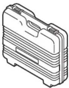
○ Case....1
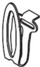
○ Hook....1
Standard accessories are subject to change without notice.
APPLICATIONS
○ Tightening and loosing various kinds of bolt and nut.
SPECIFICATIONS
| Voltage (by areas)* | (110V, 120V, 230V, 240V)~ |
| Power input* 370 W | |
| No load speed / Impact rate (A, B, C, D mode are shown in Fig. 2) | A: 0 - 1400 / 0 - 1500 min ^-1 B: 0 - 1600 / 0 - 1900 min ^-1 C: 0 - 1800 / 0 - 2300 min ^-1 D: 0 - 2100 / 0 - 2700 min ^-1 |
| Capacities (size of bolts) | M8 - M14 (High tension bolt)M10 - M18 (Ordinary bolt) |
| Tightening torque** Maximum 250 N·m | |
| Weight*** | 2.1 kg |
* Be sure to check the nameplate on product as it is subject to change by areas.
** Tightening the bolt without extension cord at rated voltage.
*** Weight: According to EPTA-Procedure 01/2014
NOTE
Due to HiKOKI's continuing program of research development, the specifications herein are subject change without prior notice.
MOUNTING AND OPERATION
CAUTION
To prevent accidents, make sure to turn the switch off and disconnect the plug from the receptacle.
| Action Figure Page | ||
| Mounting the socket (1) | 1 | 88 |
| Changing the impact rate | 2 | 88 |
| Changing the rotation direction | 3 | 88 |
| Switch operation | 4 | 88 |
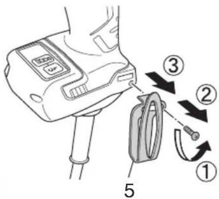
| Dismounting the hook (5) | 5 | 88 |
| Selecting accessories | — | 89 |
English
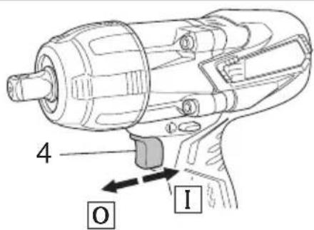
1. Switch operation (Fig. 4)
When the switch trigger (4) is depressed, rotates. When the trigger is released, the tool stops.
☐ The rotational speed can be controlled by amount that the switch trigger (4) is pulled. Speed is low when the switch trigger is pulled slightly and increases as the switch trigger is pulled more.
2. Switching tightening mode (see Fig. 2)
Each press of mode switch (2) will change the impact rate. Switch (4) must be switched OFF when conducting this operation. Use A or B for light tasks, and C or D for heavy tasks.
3. The protection function
To protect the tool, the protection function will be activated, automatically shutting down the unit in the event of any problems. (Table 1)
Table 1
| Mode Indicator Lamp (3)(see Fig. 2) | Cause of Shutdown | |
| Flashing | Fast repeated flashes Flashes on and off with 0.1-second intervals | Automatic shutdown initiated by excessive load (*1) |
| Slow repeated flashes Flashes on and off with 1-second intervals | Automatic shutdown initiated due to sensor detection trouble (*2) | |
| Flashing during mode operation | Automatic shutdown initiated due to the tool's internal temperature exceeding the specified temperature level (*3) | |
| Automatic shutdown initiated due to approximately 5 minutes of continuous no-load operation (*4) | ||
*1 Excessive load protection function
For excessive load conditions, the tool will shutdown to prevent damage.
Discontinue the heavy load task and press mode switch (2) to reset the tool.
*2 Control monitoring function
Press mode switch (2) to reset the tool.
Continual occurrences of this situation may be the result of damage to the tool.
*3 Increased temperature protection function
Automatic shutdown is activated to prevent damage from high temperatures.
The tool's internal temperature will increase involving the use of large currents of electricity, or when used in high temperature environments.
Please allow the tool to rest for 10 to 15 minutes before continuing a task.
*4 Continuous operation prevention function
Shutdown will occur in the event of continuous operation while the switch remains ON.
MAINTENANCE AND INSPECTION
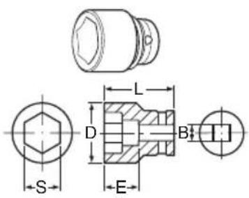
1. Inspecting the socket
A worn or deformed hex or a square-holed socket not give an adequate tightness to the fitting between the nut or anvil, consequently resulting in loss of tightening torque. Pay attention to wear of socket holes periodically, and replace with a new one if needed.
2. Inspecting the mounting screws
Regularly inspect all mounting screws and ensure that they are properly tightened. Should any of the screws be loose, retighten them immediately. Failure to do so could result in serious hazard.
3. Maintenance of the motor
the The motor unit winding is the very "heart" of the power tool. Exercise due care to ensure the winding does not vary some damaged and/or wet with oil or water.
4. Replacing supply cord
If the replacement of the supply cord is necessary, this has to be done by the manufacturer of this agent in order to avoid a safety hazard.
CAUTION
In the operation and maintenance of power tools, the safety regulations and standards prescribed in each country must be observed.
GUARANTEE
We guarantee HiKOKI Power Tools in accordance with statutory/country specific regulation. This guarantee does not cover defects or damage due to misuse, abuse, or normal wear and tear. In case of complaint, please send the Power Tool, undismantled, with the GUARANTEE CERTIFICATE found at the end of this Handling instruction, to a HiKOKI Authorized Service Center.
IMPORTANT
Correct connection of the plug
The wires of the main lead are coloured in accordance with the following code:
Blue: — Neutral
Brown: — Live
As the colours of the wires in the main lead of this tool may not correspond with the coloured markings identifying the terminals in your plug proceed as follows:
The wire coloured blue must be connected to the terminal marked with the letter N or coloured black. The wire coloured brown must be connected to the terminal marked with the letter L or coloured red. Neither core is connected to the earth terminal.
NOTE:
This requirement is provided according to BRITISH STANDARD 2769: 1984.
Therefore, the letter code and colour code may not be applicable to other markets except The United Kingdom.
Information concerning airborne noise and vibration
The measured values were determined according to EN62841 and declared in accordance with ISO 4871.
for tasks
Measured A-weighted sound power level: 98 dB (A)
Measured A-weighted sound pressure level: 111 dB (A)
Uncertainty K: 3 dB (A).
Wear hearing protection.
Vibration total values (triax vector sum) determined according to EN62841.
Impact tightening of fasteners of the maximum capacity of the tool:
Vibration emission value a_h = 13.2 m/s^2
Uncertainty K = 1.5 m/s²
The declared vibration total value has been measured in accordance with a standard test method and may be used for comparing one tool with another.
It may also be used in a preliminary assessment of exposure.
WARNING
☐ The vibration emission during actual use of the power tool can differ from the declared total value depending in the ways in which the tool is used.
○ Identify safety measures to protect the operator that are based on an estimation of exposure in the actual conditions of use (taking account of all parts of the operating cycle such as the times when the tool is switched off and when it is running idle in addition to the trigger time).
NOTE
Due to HiKOKI's continuing program of research and development, the specifications herein are subject to change without prior notice.
ALLGEMEINE
○ Koffer....1
○ Haken....1
VEDLIKEHOLD OG INSPEKSJON
1. Inspiserer kontakten
text_image
Diagram of a mechanical device with labeled rotation arrows and component symbols4
text_image
4 O I5
text_image
Diagram showing a device with labeled parts and directional arrows indicating motion or sequence.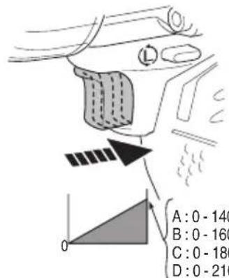
text_image
A: 0 - 140 B: 0 - 160 C: 0 - 180 D: 0 - 210B = 12.7 mm
text_image
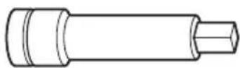
Technical drawing of a mechanical component with labeled dimensions including S, E, D, L, and B| S D E L S D E L | |||||||||
| 12 20 34 52 955138 | |||||||||
| 13 21 .5 34 52 955139 | |||||||||
| 14 25 | 24 40 | 873540 | 14 22 34 | 52 955140 | |||||
| 17 28 | 15 32 | 873536 | 17 25 34 | 52 955141 | |||||
| 19 28 | 17 34 | 873624 | 19 28 34 | 52 955142 | |||||
| 21 32 | 20 36 | 873626 | 21 31 34 | 52 955143 | |||||
| 22 35 | 24 40 | 873627 | 22 32.5 | 34 52 955144 | |||||
| 23 36 | 25 40 | 873628 | 23 33 34 | 52 955145 | |||||
| 24 38 | 25 40 | 873629 | 24 34 34 | 52 955146 | |||||
| 26 38 | 25 40 | 873630 | 26 38 57 | 75 955147 | |||||
| 27 42 | 24 50 | 985195 | 27 40 57 | 75 955148 | |||||
873633
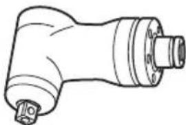
natural_image
Line drawing of a mechanical device casing with internal compartments (no text or symbols)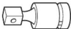
986062
335724
natural_image
Line drawing of a mechanical component with no visible text or symbolsEW-14R
natural_image
Line drawing of a quill pen with inkwell (no text or symbols)| English Dansk Română | ||||
| GUARANTEE CERTIFICATE1 Model No.2 Serial No.3 Date of Purchase4 Customer Name and Address5 Dealer Name and Address(Please stamp dealer name and address) | GARANTIBEVIS1 Modelnummer2 Serienummer3 Købsdato4 Kundes navn og adresse5 Forhandlers navn og adresse(Indsæt stempel med forhandlers navn og adresse) | CERTIFICAT DE GARANTIE1 Model nr.2 Nr. de serie3 Data cumpărării4 Numele și adresa clientului5 Numele și adresa distributorului(Vă rugăm aplicați ștampila cu numele și adresa distributorului) | ||
| Deutsch Norsk Slovenščina | ||||
| GARANTIESCHEIN1 Modell-Nr.2 Serien-Nr.3 Kaufdatum4 Name und Anschrift des Kunden5 Name und Anschrift des Händlers(Bitte mit Namen und Anschrift des Handlers abstempeln) | GARANTISERTIFIKAT1 Modellnr.2 Serienr.3 Kjopsdato4 Kundens navn og adresse5 Forhandlerens navn og adresse(Vennligst stemple forhandlerens navn og adresse) | GARANCIJSKO POTRDILO1 Št. modela2 Serijska št.3 Datum nakupa4 Ime in naslov kupca5 Ime in naslov prodajalca(Prosimo vitsnite žig z imenom in naslovom prodajalca) | ||
| Français Suomi Slovenčina | ||||
| CERTIFICAT DE GARANTIE1 No. de modèle2 No de série3 Date d'achat4 Nom et adresse du client5 Nom et adresse du revendeur(Cachet portant le nom et l'adresse du revendeur) | TAKUUTODISTUS1 Malli nro2 Sarja nro3 Ostopäivämäärä4 Asiakkaan nimi ja osoite5 Myyjän nimi ja osoite(Leimaa myyjän nimi ja osoite) | ZÁRUČNÝ LISTA1 Č. modelu2 Sérlövé č.3 Dátum zakúpenia4 Meno a adresa zákaznika5 Názov a adresa predajcu(Pečiatka s názvom a adresou predajcu) | ||
| Italiano Ελλημικά Βългарски | ||||
| CERTIFICATO DI GARANZIA1 Modello2 N° di serie3 Data di acquisto4 Nome e indirizzo dell'acquirente5 Nome e indirizzo del rivenditore(Si prega di apporre il timbro con questi dati) | ПІЗТОПОІНТІКО ЕГГУНЄНЗ1 Ар. Movtėlou2 Aŭξων Ap.3 Нμερομηνία αγοράς4 ́Овоја кай дієŭθυνση πελάτη5 ́Овоја кай дієŭθυνση μεταπωλητή(Παροκαλούμε να χρησμοποιηθεί σφραγίδα) | ГАРАНЦИОНЕН СЕРТИФИКАТ1 Модел No2 Сериен No3 Дата за закупуване4 Име и адрес на клиента5 Име и адрес на търговеца(Моля, отпечатайте името и адрес на дильра) | ||
| Nederlands Polski Srpski | ||||
| GARANTIEBEWIJS1 Modelnummer2 Serienummer3 Datum van aankoop4 Naam en adres van de gebruiker5 Naam en adres van de handelaar(Stempel a.u.b. naam en adres vande de handelaar) | GWARANCJA1 Model2 Numer seryjny3 Data zakupu4 Nazwa klienta i adres5 Nazwa dealera i adres(Pieczęć punktu sprzedaży) | GARANTNI SERTIFIKAT1 Br. modela.2 Serijski br.3 Datum kupovine4 Ime i adresa kupca5 Ime i adresa prodavca(Molimo da stavite pečat na ime i adresu trgovca) | ||
| Español Magyar Hrvatski | ||||
| CERTIFICADO DE GARANTÍA1 Número de modelo2 Número de serie3 Fecha de adquisición4 Nombre y dirección del cliente5 Nombre y dirección del distribuidor(Se ruega poner el sello del distribuidor con su nombre y dirección) | GARANCIA BIZONYLAT1 Tipusszám2 Sorozatszám3 A vásárlás dátuma4 A Vásárló neve és címe5 A Kereskedő neve és címe(Kérjük ide elholyezni a Kereskedő nevének és címének pecsétjét) | JAMSTVENI CERTIFIKAT1 Br modela.2 Serijski br.3 Datum kupnje4 Ime i adresa kupca5 Ime i adresa trgovca(Molimo stavite pečat na ime i adresu trgovca) | ||
| Português Čeština | ||||
| CERTIFICADO DE GARANTIA1 Número do modelo2 Número do série3 Data de compra4 Nome e morada do cliente5 Nome e morada do distribuidor(Por favor, carimbe o nome e morada do distribuidor) | ZÁRUČNÍ LIST1 Model č.2 Série č.3 Datum nákupu4 Jméno a adresa zákazníka5 Jméno a adresa prodejce(Prosíme o razítko se jménem a adresou prodejce) | |||
| Svenska Türkçe | ||||
| GARANTICERTIFIKAT1 Modellnr2 Serienr3 Inköpsdatum4 Kundens namn och adress5 Försäljarens namn och adress(Stàmpla försäljarens namn och adress) | GARANTI SERTÍFÍKASI1 Model No.2 Seri No.3 Satin Alma Tarihi4 Müşteri Adı ve Adresi5 Bayi Adı ve Adresi(Lüften bayi adını ve adresini kaşe olarak basin) | |||
HiKOKI
| 1 | |
| 2 | |
| 3 | |
| 4 | |
| 5 |
Siemensring 34, 47877 willich, Germany
Tel: +49 2154 49930
Fax: +49 2154 499350
URL: http://www.hikoki-powertools.de
Hikoki Power Tools Netherlands B.V.
Brabanthaven 11, 3433 PJ Nieuwegein, The Netherlands
Tel: +31 30 6084040
Fax: +31 30 6067266
URL: http://www.hikoki-powertools.nl
Hikoki Power Tools (U.K.) Ltd.
Precedent Drive, Rooksley, Milton Keynes, MK
United Kingdom
Tel: +44 1908 660663
Fax: +44 1908 606642
URL: http://www.hikoki-powertools.uk
Hikoki Power Tools France S.A.S.
Hikoki Power Tools Belgium N.V./S.A.
Koningin Astridlaan 51, B-1780 Wemmel, Belgium
Tel: +32 2 460 1720
Fax: +32 2 460 2542
URL http://www.hikoki-powertools.be
Hikoki Power Tools Italia S.p.A
Via Piave 35, 36077, Altavilla Vicentina (VI), Italy
Tel: +39 0444 548111
Fax: +39 0444 548110
URL: http://www.hikoki-powertools.it
Hikoki Power Tools Ibérica, S.A.
C/ Puigbarral, 26-28, Pol. Ind. Can Petit, 08227 Terrassa
(Barcelona), Spain
Tel: +34 93 735 6722
Fax: +34 93 735 7442
URL: http://www.hikoki-powertools.es
Kjeller Vest 7, N-2007 Kjeller, Norway
Tel: (+47) 6692 6600
Fax: (+47) 6692 6650
URL: http://www.hikoki-powertools.no
Hikoki Power Tools Sweden AB
Rotebergsvagen 2B SE-192 78 Sollentuna, Sweden
Tel:(+46)859899900
Fax: (+46) 8 598 999 40
URL: http://www.hikoki-powertools.se
Hikoki Power Tools Denmark A/S
Hikoki Power Tools Romania S.R.L.
Ring Road, No. 66, Mustang Traco Warehouses, Warehouse
No.1, Pantelimon City, 077145, Ilfov County, Romania