
LDU4 - Drill HiKOKI - Free user manual and instructions
Find the device manual for free LDU4 HiKOKI in PDF.


| Product Type | Cordless Drill Driver |
| Brand | HiKOKI |
| Model | LDU4 |
| Power Source | 14.4 V Lithium-Ion Battery |
| Battery Capacity | 1.5 Ah (typical) |
| Chuck Type | Keyless, 0.8-10 mm |
| Max Torque | 30 Nm |
| No-Load Speed | 0-600 / 0-1800 RPM (variable) |
| Speed Settings | 2-speed gearbox |
| Functions | Drilling, Screwdriving |
| Forward/Reverse | Yes |
| Variable Speed Trigger | Yes |
| LED Light | Yes |
| Belt Clip | Yes |
| Dimensions (L x W x H) | 200 x 65 x 210 mm |
| Weight (including battery) | 1.4 kg |
| Maintenance & Cleaning | Wipe with dry cloth; keep vents clean |
| Safety Features | Overload protection, lock-off button |
| Spare Parts Available | Battery, charger, chuck, brushes |
| Reparability | Serviceable by authorized centers |
| General Information | HiKOKI LDU4 cordless drill for DIY and professional use |
Frequently Asked Questions - LDU4 HiKOKI
User questions about LDU4 HiKOKI
0 question about this device. Answer the ones you know or ask your own.
Ask a new question about this device
Download the instructions for your Drill in PDF format for free! Find your manual LDU4 - HiKOKI and take your electronic device back in hand. On this page are published all the documents necessary for the use of your device. LDU4 by HiKOKI.
USER MANUAL LDU4 HiKOKI
Read through carefully and understand these instructions before use. Leer cuidadosamente y comprender estas instrucciones antes del uso.
使用前務請詳加閱讀
1

2

3
| English Español 中國語 | |||
| 1 | Spindle | Husillo | 主軸 |
| 2 | Collet chuck | Boquilla de mordazas | 套爪夾盤 |
| 3 | Tighten | Apretar | 擰緊 |
| 4 | Nose bracket | Ménsula del nariz | 鼻形支撐架 |
| 5 | Tapered portion | Parte cónica | 楔形部分 |
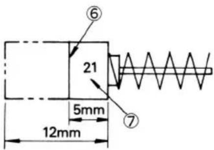
| 6 | Wear limit | Límite de desgaste | 磨損極限 |
| 7 | No. of carbon brush | No. de escobilla de carbón | 碳刷號 |
GENERAL SAFETY RULES
WARNING!
Read all instructions
Failure to follow all instructions listed below may result in electric shock, fire and/or serious injury.
The term "power tool" in all of the warnings listed below refers to your mains operated (corded) power tool or battery operated (cordless) power tool.
SAVE THESE INSTRUCTIONS
1) Work area
a) Keep work area clean and well lit.
Cluttered and dark areas invite accidents.
b) Do not operate power tools in explosive atmospheres, such as in the presence of flammable liquids, gases or dust.
Power tools create sparks which may ignite the dust of fumes.
c) Keep children and bystanders away while operating a power tool.
Distractions can cause you to lose control.
2) Electrical safety
a) Power tool plugs must match the outlet.
Never modify the plug in any way.
Do not use any adapter plugs with earthed (grounded) power tools.
Unmodified plugs and matching outlets will reduce risk of electric shock.
b) Avoid body contact with earthed or grounded surfaces such as pipes, radiators, ranges and refrigerators. There is an increased risk of electric shock if your body is earthed or grounded.
c) Do not expose power tools to rain or wet conditions. Water entering a power tool will increase the risk of electric shock.
d) Do not abuse the cord. Never use the cord for carrying, pulling or unplugging the power tool. Keep cord away from heat, oil, sharp edges or moving parts. Damaged or entangled cords increase the risk of electric shock.
e) When operating a power tool outdoors, use an extension cord suitable for outdoor use.
Use of a cord suitable for outdoor use reduces the risk of electric shock
3) Personal safety
a) Stay alert, watch what you are doing and use common sense when operating a power tool.
Do not use a power tool while you are tired or under the influence of drugs, alcohol or medication.
A moment of inattention while operating power tools may result in serious personal injury.
b) Use safety equipment. Always wear eye protection. Safety equipment such as dust mask, non-skid safety shoes, hard hat, or hearing protection used for appropriate conditions will reduce personal injuries.
c) Avoid accidental starting. Ensure the switch is in the off position before plugging in.
Carrying power tools with your finger on the switch or plugging in power tools that have the switch on invites accidents.
d) Remove any adjusting key or wrench before turning the power tool on. A wrench or a key left attached to a rotating part of the power tool may result in personal injury.
e) Do not overreach. Keep proper footing and balance at all times.
This enables better control of the power tool in unexpected situations.
f) Dress properly. Do not wear loose clothing or jewellery. Keep your hair, clothing and gloves2©way from moving parts.
Loose clothes, jewellery or long hair can be caught in moving parts.
g) If devices are provided for the connection of dust extraction and collection facilities, ensure these are connected and properly used.
Use of these devices can reduce dust related hazards.
4) Power tool use and care
a) Do not force the power tool. Use the correct power tool for your application.
The correct power tool will do the job better and safer at the rate for which it was designed.
b) Do not use the power tool if the switch does not turn it on and off.
Any power tool that cannot be controlled with the switch is dangerous and must be repaired.
c) Disconnect the plug from the power source before making any adjustments, changing accessories, or storing power tools.
Such preventive safety measures reduce the risk of starting the power tool accidentally.
d) Store idle power tools out of the reach of children and do not allow persons unfamiliar with the power tool or these instructions to operate the power tool.
Power tools are dangerous in the hands of untrained users.
e) Maintain power tools. Check for misalignment or binding of moving parts, breakage of parts and any other condition that may affect the power tools operation.
If damaged, have the power tool repaired before use.
Many accidents are caused by poorly maintained power tools.
f) Keep cutting tools sharp and clean.
Properly maintained cutting tools with sharp cutting edges are less likely to bind and are easier to control.
g) Use the power tool, accessories and tool bits etc., in accordance with these instructions and in the manner intended for the particular type of power tool, taking into account the working conditions and the work to be performed.
Use of the power tool for operations different from intended could result in a hazardous situation.
5) Service
a) Have your power tool serviced by a qualified repair person using only identical replacement parts.
This will ensure that the safety of the power tool is maintained.
PRECAUTION
Keep children and infirm persons away.
When not in use, tools should be stored out of reach of children and infirm persons.
PRECAUTIONS ON USING GRINDER
- Always use for the right purpose under safe conditions.
This machine is a portable tool for grinding or finishing work on metal of various types, resin and ceramics. Use the machine for these purposes only.
- Always use regulation grinding wheels.
The grinding wheel for this machine should be grinding wheel with axle which have a maximum diameter of 18 mm and an axle diameter of 3 mm or 6 mm.
- Always test before using.
Always check the grinding wheel to be used for cracks or splits. Also, always test-run the machine before using to check for any abnormalities.
- Protect the eyes with protective goggles.
Always wear protective goggles during grinding. Also, when there is a lot of dust produced by grinding, wear a mask.
- Always hold the machine securely.
Always hold the machine securely when using. If you do not hold the machine, the reaction to force can cause it to spring back.
- Do not place unreasonable loads on the machine.
Do not place unreasonable loads on the machine by pressing it so hard against the material that the rotation speed is drastically reduced. This will reduce work efficiency and there is a danger that the grinding wheel axle will be bent.
- Never touch revolving parts.
Keep hands and other body parts away from the vicinity of the grinding wheel while it is spinning to avoid danger of cuts, abrasions or catching clothes in equipment.
- Be careful about sparks from grinding.
Grinding particles can become flying sparks. Always keep flammable materials and materials which can easily be damaged in a safe place removed from the work area. Also, be careful that sparks do not come in direct contact with hands or feet.
- Do not put the machine down while it is still running.
Never run the machine if you are not holding it securely with both hands. Also, never put the machine on the table or floor while it is still running.
- Follow the correct order when replacing the grinding wheel.
When replacing the grinding wheel, carefully follow the steps outlined in this instruction manual.
- Use only grinding wheels with a "Safe Speed" at least as high as the "No-Load RPM" indicated on the power tool nameplate.
SPECIFICATIONS
| Voltage (by areas)* (110V, 115V, 120V, 127V, 220V, 230V, 240V) | |
| Input* 240 W | |
| No-Load Speed* 23000 / min | |
| Mounted Wheel Maximum 32 mm | Shaft diameter 6 mm |
| Weight (without cord) 1.9 kg | |
*Be sure to check the nameplate on product as it is subject to change by areas.
STANDARD ACCESSORIES
(1) Mounted wheels (No. KA-1, 2, 4, 5, 6)....5
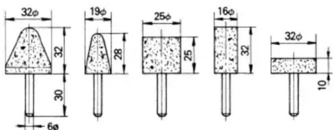
KA-1 KA-2 KA-4 KA-5 KA-6
(2) Dresser .... 1
(3) Wrench 1
(4) Wrench 1
(5) Case 1
Standard accessories are subject to change without notice.
OPTIONAL ACCESSORIES (sold separately)
○Mounted wheels with 6 mm shaft
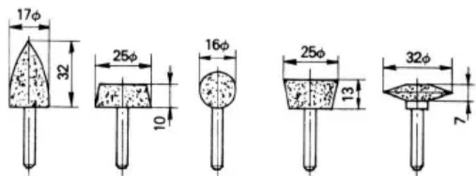
KA-3 KA-7 KA-8 KA-9
KA-10
○Collet chuck for 3 mm shaft
The 3mm collet chuck is designed to accept mounted wheels with a 3mm diameter shaft for processing small parts.
Dimensions and handling methods other than the shaft hole are the same as those for the 6 mm collet chuck.
○Mounted wheels with 3 mm shaft
All mounted wheels are provided with WA grain, 80 grounding, and P bonding and are suitable for grinding general and special steel materials.
Purchase and utilize mounted wheels of suitable shape for processing.
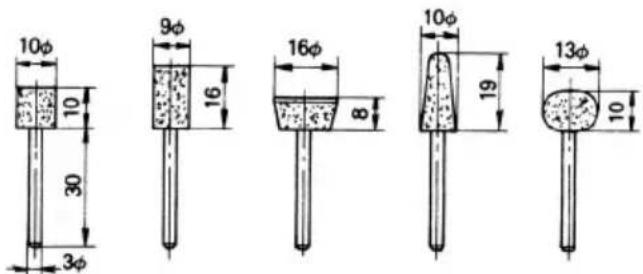
KA-20 KA-21 KA-22 KA-23 KA-24
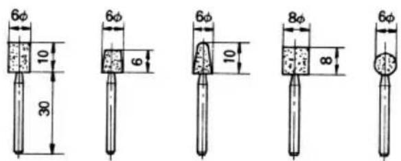
KC-20 KC-21 KC-22 KC-23 KC-24
○Universal mount
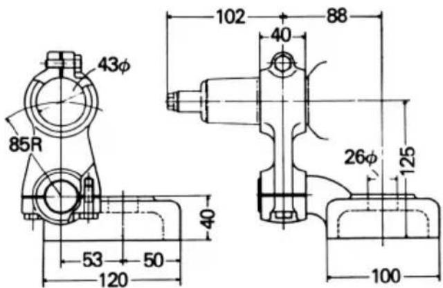
This universal mount is used when grinding inner surfaces of workpieces or finishing specially shaped workpieces, by installing the hand grinder on a lathe. The universal mount is installed on the cross slide after removing the lathe tool post.
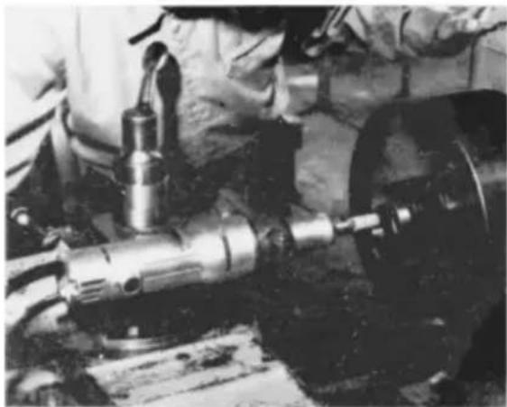
(using universal mount)

(dimensional diagram)
Optional accessories are subject to change without notice.
APPLICATIONS
○Finishing of dies for press working, die casting and moulding.
○Finishing of thread cutting dies, tools and other small parts.
○Internal grinding of tools and machine parts.
PRIOR TO OPERATION
1. Power source
Ensure that the power source to be utilized conforms to the power requirements specified on the product nameplate.
2. Grounding
This tool should be grounded while in use to protect the operator from electric shock. The tool is equipped with a three conductor cord and grounding type plug to fit the proper grounding type receptacle. The green (or green and yellow) conductor in the cord is the grounding wire. Never connect the green (or green and yellow) wire to a live terminal.
3. Power switch
Ensure that the power switch is in the OFF position. If the plug is connected to a receptacle while the power switch is in the ON position, the power tool will start operating immediately, which could cause a serious accident.
4. Extension cord
When the work area is removed from the power source, use an extension cord of sufficient thickness and rated capacity. The extension cord should be kept as short as practicable.
5. Confirming condition of the environment
Confirm that the work site is placed under appropriate conditions conforming to prescribed precautions. When grinding a thin steel plate, depending upon the state of the workbench, a loud noise will be created due to resounding noise from the steel plate being ground. To eliminate unwanted noise in this instance, place a rubber mat beneath the material to be ground.
6. Installing a mounted wheel
●Always use a mounted wheel whose outer diameter is 32 mm or less. When using a mounted wheel in excess of this diameter, mounted wheel circumferential speed will exceed the safety limit, perhaps causing an accident.
Never use a mounted wheel in excess of 32 mm diameter.
●Mounted wheels can be simply attached and detached by using two wrenches. (Refer to Fig. 1).
●Install a mounted wheel so that the mounted wheel shaft does not protrude more than 15 mm.
Note:
-
Do not tighten the collet chuck by inserting a shaft thinner than the regular shaft diameter (6 mm) in the chuck or in an empty condition. This practice will damage the collet chuck.
-
When installing a mounted wheel with shaft, tighten the collet chuck after applying a small quantity of spindle oil (or sewing machine oil) to the tapered portion indicated in Fig. 2.
MOUNTED WHEEL SELECTING METHOD
Mounted wheels attached to this hand grinder are suitable for grinding press and die cast molds, and other hard or mild steel parts. (Except stainless plate.) Types of mounted wheel are varied according to the materials to be ground. Select a mounted wheel appropriate for the material to be ground.
●The following table is an outline of mounted wheel and materials to be ground.
| Materials to be ground Grain Grading | Bonding degree | Structure Bonding agent | |
| Mild steel, hard steel, forged steel | WA 60 ~ 80 P m V | ||
| Cast iron C 36 M - O m V | |||
| Brass, bronze, aluminium | C 36 J - K m V | ||
| Ceramic | WA 60 ~ 80 | M | m V |
| Synthetic resin | C 36 K - M m V |
●Small-scaled mounted wheels with shaft are prepared for grinding small surfaces. Since mounted wheel shaft diameter in 3 mm, use the collet chuck for 3 mm shaft sold separately by your HiKOKI dealer as an optional accessory.
HOW TO USE
1. Switching operation
(1) When throwing the switch lever to the right (ON side), power is applied; when throwing it to the left (OFF side), power is switched off.
(2) When first throwing the switch after installing a new mounted wheel, avoid personal proximity to the mounted wheel revolving circumference to avoid danger of a possible imperfection.
2. Precautions on operation
(1) Lightly press the mounted wheel to the material to be ground
When grinding materials, high-speed revolution is necessary. Use a hand grinder with high-speed revolution, minimizing the pressing force.
(2) Dressing the mounted wheel
●After attaching a mounted wheel, correct deflection of the mounted wheel center by using a dresser. If the mounted wheel center is eccentric, not only precise finishing cannot be achieved but also grinder vibration increases, lowering grinder accuracy and durability.
●A clogged or worn mounted wheel will soil the finishing surface or lower grinding efficiency. Occasionally dress the mounted wheel by applying the dresser.
MAINTENANCE AND INSPECTION
1. Inspecting the mounted wheel
Ensure that the mounted wheel is free of cracks and surface defects.
2. Inspecting the mounting screws
Regularly inspect all mounting screws and ensure that they are properly tightened. Should any of the screws be loose, retighten them immediately. Failure to do so could result in serious hazard.
3. Maintenance of the motor
The motor unit winding is the very "heart" of the power tool.
Exercise due care to ensure the winding does not become damaged and/or wet with oil or water.
4. Inspecting the carbon brushes (Fig. 3)
The motor employs carbon brushes which are consumable parts. Since an excessively worn carbon brush can result in motor trouble, replace the carbon brushes with new ones having the same carbon brush No. shown in the figure when it becomes worn to or near the "wear limit". In addition, always keep carbon brushes clean and ensure that they slide freely within the brush holders.
5. Replacing carbon brushes
Disassemble the brush caps with a slotted-head screwdriver. The carbon brushes can then be easily removed.
6. Service parts list
CAUTION
Repair, modification and inspection of HiKOKI Power Tools must be carried out by an HiKOKI Authorized Service Center.
This Parts List will be helpful if presented with the tool to the HiKOKI Authorized Service Center when requesting repair or other maintenance.
In the operation and maintenance of power tools, the safety regulations and standards prescribed in each country must be observed.
MODIFICATIONS
HiKOKI Power Tools are constantly being improved and modified to incorporate the latest technological advancements.
Accordingly, some parts may be changed without prior notice.
NOTE:
Due to HiKOKI's continuing program of research and development, the specifications herein are subject to change without prior notice.
KA-1 KA-2 KA-4 KA-5 KA-6
(2) Reacondicionadora .... 1
(3) Llave 1
(4) Llave 1
(5) Caja 1
KA-3 KA-7 KA-8 KA-9 KA-10
KA-20 KA-21 KA-22 KA-23 KA-24
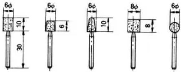
KC-20 KC-21 KC-22 KC-23 KC-24
○Montaje universal
KA-1 KA-2 KA-4 KA-5 KA-6
KA-3 KA-7 KA-8 KA-9 KA-10
○3 mm旋轉軸用的彈簧筒夾頭
(用萬能架)
(尺寸示意圖)
選購附件可能不預先通告而徑予更改。
用途
| Item No. | Part Name |
| 34 | Machine Screw M4×45 |
| 36 | Collet Chuck |
| 37 | Brush Cap |
| 38 | Name Plate |
| 39 | Rivet D2.5×3.8 |
| 40 | Tail Cover |
| 41 | Switch Holder |
| 42 | Hexagon Socket Hd. Bolt M4×12 |
| 43 | Spring Lock Wasfer |
| 44B | Switch |
| 45 | Cord |
| 46 | Cord Armor |
| 47 | Cord Crip |
| 49 | Connector |
| 50B | Carbon Brush |
| 51 | Wrench 12mm |
| 52 | Wrench 17mm |
| 53 | Dresser |
| 54 | Mounted Wheel KA-1 |
| 55 | Mounted Wheel KA-2 |
| 57 | Mounted Wheel KA-4 |
| 58 | Mounted Wheel KA-5 |
| 59 | Mounted Wheel KA-6 |
| 64B | Case |
| 65 | Machine Screw M4×6 |
| 69 | Machine Screw M4×14 |
| 70 | Spring Loch Washer |
| 71 | Rubber Cap |
| 72 | Switch Insulator |
| 73 | Terminal D4 |
| Item No. | Part Name |
| 1C | Housing Ass'y |
| 2 | Bearing Lock |
| 3 | Stator Ass'y |
| 4A | Brush Terminal |
| 5 | Machine Screw M4×60 |
| 6 | Spring Lock Washer |
| 7C | Brush Holder |
| 8A | Hexagon Socket Hd. Set Screw M4×10 |
| 9 | Stop Plate |
| 10B | Rubber Washer |
| 11 | Armature |
| 13 | Ball Bearing (626DC2) |
| 14 | Bearing Washer |
| 15 | Inner Cover |
| 16 | Bearing Cover (A) |
| 17 | Machine Screw M4×10 |
| 18 | Ball Bearing (608VVC2) |
| 19 | Spring Lock Washer |
| 20 | Nose Bracket |
| 21 | Ball Bearing (6000VVCM) |
| 22 | Wave Washer |
| 23 | Bearing Plate |
| 26 | Spindle |
| 27 | Coupling |
| 28 | Ball Bearing (6001VVCMPS2-L) |
| 29 | Ring |
| 30 | Washer (A) |
| 31 | Washer (B) |
| 32 | Bearing Lid |
| 33 | Hexagon Socket Hd. Set Screw M4×5 |


Koki Holdings Co., Ltd.
806
Code No. C99016133 N
Printed in Japan

- GENERAL SAFETY RULES
- WARNING
- READ ALL INSTRUCTIONS
- SAVE THESE INSTRUCTIONS
- WORK AREA
- ELECTRICAL SAFETY
- PERSONAL SAFETY
- POWER TOOL USE AND CARE
- SERVICE
- PRECAUTION
- PRECAUTIONS ON USING GRINDER
- STANDARD ACCESSORIES
- OPTIONAL ACCESSORIES (SOLD SEPARATELY)
- ○MOUNTED WHEELS WITH 3 MM SHAFT
- ○UNIVERSAL MOUNT
- APPLICATIONS
- PRIOR TO OPERATION
- POWER SOURCE
- GROUNDING
- POWER SWITCH
- EXTENSION CORD
- CONFIRMING CONDITION OF THE ENVIRONMENT
- INSTALLING A MOUNTED WHEEL
- NOTE
- MOUNTED WHEEL SELECTING METHOD
- HOW TO USE
- SWITCHING OPERATION
- PRECAUTIONS ON OPERATION
- DRESSING THE MOUNTED WHEEL
- MAINTENANCE AND INSPECTION
- INSPECTING THE MOUNTED WHEEL
- INSPECTING THE MOUNTING SCREWS
- MAINTENANCE OF THE MOTOR
- INSPECTING THE CARBON BRUSHES (FIG. 3)
- REPLACING CARBON BRUSHES
- SERVICE PARTS LIST
- CAUTION
- MODIFICATIONS
- 用途
- KOKI HOLDINGS CO., LTD
Brand : HiKOKI
Model : LDU4
Category : Drill