
GSB 18V28 Professional - Drill BOSCH - Free user manual and instructions
Find the device manual for free GSB 18V28 Professional BOSCH in PDF.
| Product Type | Cordless Hammer Drill/Driver |
| Brand | Bosch |
| Model | GSB 18V28 Professional |
| Rated Voltage | 18 V |
| Battery Type | Lithium-ion (compatible GBA 18V...) |
| Recommended Charger | AL 18... or GAL 18... |
| No-Load Speed (1st Gear) | 0 – 500 rpm |
| No-Load Speed (2nd Gear) | 0 – 1,900 rpm |
| Max. Torque (Hard/Soft) | 63 / 31 Nm |
| Max. Drilling Diameter in Wood | 82 mm |
| Max. Drilling Diameter in Steel | 13 mm |
| Max. Drilling Diameter in Masonry | 28 mm |
| Chuck | Keyless Chuck 13 mm |
| Weight (with Battery) | Approx. 2.3 kg |
| Dimensions (L x W x H) | Approx. 260 x 80 x 210 mm |
| Main Functions | Drilling, Screwdriving, Hammering |
| Settings | Variable Speed, Reversible Rotation, Adjustable Torque (20+1 Positions) |
| Safety | Chuck Brake, Anti-Restart Protection, Overload Protection |
| Lighting | Integrated Work LED |
| Maintenance and Cleaning | Clean Ventilation Slots with a Dry Brush; Remove Battery Before Maintenance |
| Spare Parts and Repairability | Spare Parts Available via Bosch Customer Service (www.bosch-pt.com) |
| General Information | Delivered in a Cardboard Box, with Battery and Charger (Depending on Version) |
Frequently Asked Questions - GSB 18V28 Professional BOSCH
User questions about GSB 18V28 Professional BOSCH
0 question about this device. Answer the ones you know or ask your own.
Ask a new question about this device
Download the instructions for your Drill in PDF format for free! Find your manual GSB 18V28 Professional - BOSCH and take your electronic device back in hand. On this page are published all the documents necessary for the use of your device. GSB 18V28 Professional by BOSCH.
USER MANUAL GSB 18V28 Professional BOSCH
OBJ_BUCH-283-014.book Page 1 Thursday, August 17, 2017 3:16 PM
Robert Bosch Power Tools GmbH
70538 Stuttgart
GERMANY
www.bosch-pt.com
160992A3XU 2017.08)PS/272

GBH Professional
36V-LIPlus|36VF-LIPlus

BOSCH
Original borgarsions
Sv Buksanyisigj original
no Original driftinsstrui
fikAkuperaiset ojee
ellipotana sanyw xphang
tr Original Islet metalat
pl Instruktie oryginalna
cs Puvcdn havod k pouzwan
SKYVHYHAVOHNPOUZHE
Wu CuiZhou Hua Zhi You Liang
P
UK OoHnHaHcHcKuHs3
EKCNYATAH
kk NanaaHy HcyaybFLH
TYHHYCKBC
16 Instncturion
bgOpHAFHnHcHcyK|V
mk OpnHnHaHOynantTa a pabora
sr Originalno upstvo 2a rad
sizvira na vodila
FRONGRAMEUPCOTZARAC
et Aupane aaschusjennis
Internal Instability
1
b

2
Deutsch. 6
English
Francais .Page 22
Espanol. Pagina 31
Portugues . Pagina 40
Italiano 49
Nederlands.. 58
Dansk . 66
Svenska Sida 74
Norsk. Side 81
Suomi. Sivu 88
EAAVikd 2eA18a96
Türkce. Sayfa 104
Polski Strona 113
Cesky Strana 122
Slovensky Strana 129
Magyar Oldal 137
Pycckn CtpaHua 146
YkpaHcbKa CToPiHa 156
Kaazakwa. 165
Româna. . 174
Блгарский... Ctrpanuca 183
MaKeDoHcKn CtpaHa 192
Srprski Strana 201
Slovensko Stran 209
General Power Tool SafetyWarnings

WARNING
Read all safety warnings and all instructions. Failure to follow the warnings and
instructions may result in electric shock, fire and/or serious injury.
Save all warnings and instructions for future reference.
The term "power tool" in the warnings refers to your mains-operated (corded) power tool or battery-operated (cordless) power tool.
Work area safety
- Keep work area clean and well lit. Cluttered or dark areas invite accidents.
Do not operate power tools in explosive atmospheres, such as in the presence of flammable liquids, gases or dust. Power tools create sparks which may ignite the dust or fumes. - Keep children and bystanders away while operating a power tool. Distractions can cause you to lose control.
Electrical safety
Power tool plugs must match the outlet. Never modify the plug in any way. Do not use any adapter plugs with earthed (grounded) power tools. Unmodified plugs and matching outlets will reduce risk of electric shock.
Avoid body contact with earthed or grounded surfaces, such as pipes, radiators, ranges and refrigerators.
There is an increased risk of electric shock if your body is earthed or grounded.
Do not expose power tools to rain or wet conditions. Water entering a power tool will increase the risk of electric shock.
English | 15
Do not abuse the cord. Never use the cord for carrying, pulling or unplugging the power tool. Keep cord away from heat, oil, sharp edges and moving parts. Damaged or entangled cords increase the risk of electric shock.
When operating a power tool outdoors, use an extension cord suitable for outdoor use. Use of a cord suitable for outdoor use reduces the risk of electric shock.
If operating a power tool in a damp location is unavoidable, use a residual current device (RCD) protected supply. Use of an RCD reduces the risk of electric shock.
Personal safety
Stay alert, watch what you are doing and use common sense when operating a power tool. Do not use a power tool while you are tired or under the influence of drugs, alcohol or medication. A moment of inattention while operating power tools may result in serious personal injury.
Use personal protective equipment. Always wear eye protection. Protective equipment such as dust mask, non-skid safety shoes, hard hat, or hearing protection used for appropriate conditions will reduce personal injuries.
Prevent unintentional starting. Ensure the switch is in the off-position before connecting to power source and/or battery pack, picking up or carrying the tool.
Carrying power tools with your finger on the switch or energising power tools that have the switch on invites accidents.
Remove any adjusting key or wrench before turning the power tool on. A wrench or a key left attached to a rotating part of the power tool may result in personal injury.
Do not overreach. Keep proper footing and balance at all times. This enables better control of the power tool in unexpected situations.
Dress properly. Do not wear loose clothing or jewellery. Keep your hair, clothing and gloves away from moving parts. Loose clothes, jewellery or long hair can be caught in moving parts.
If devices are provided for the connection of dust extraction and collection facilities, ensure these are connected and properly used. Use of dust collection can reduce dust-related hazards.
Power tool use and care
Do not force the power tool. Use the correct power tool for your application. The correct power tool will do the job better and safer at the rate for which it was designed.
Do not use the power tool if the switch does not turn it on and off. Any power tool that cannot be controlled with the switch is dangerous and must be repaired.
- Disconnect the plug from the power source and/or the battery pack from the power tool before making any adjustments, changing accessories, or storing power tools. Such preventive safety measures reduce the risk of starting the power tool accidentally.
Store idle power tools out of the reach of children and do not allow persons unfamiliar with the power tool or
these instructions to operate the power tool. Power tools are dangerous in the hands of untrained users.
- Maintain power tools. Check for misalignment or binding of moving parts, breakage of parts and any other condition that may affect the power tool's operation. If damaged, have the power tool repaired before use.
Many accidents are caused by poorly maintained power tools.
- Keep cutting tools sharp and clean. Properly maintained cutting tools with sharp cutting edges are less likely to bind and are easier to control.
- Use the power tool, accessories and tool bits etc. in accordance with these instructions, taking into account the working conditions and the work to be performed. Use of the power tool for operations different from those intended could result in a hazardous situation.
Battery tool use and care
- Recharge only with the charger specified by the manufacturer. A charger that is suitable for one type of battery pack may create a risk of fire when used with another battery pack.
Use power tools only with specifically designated battery packs. Use of any other battery packs may create a risk of injury and fire.
When battery pack is not in use, keep it away from other metal objects, like paper clips, coins, keys, nails, screws or other small metal objects, that can make a connection from one terminal to another. Shorting the battery terminals together may cause burns or a fire.
Under abusive conditions, liquid may be ejected from the battery; avoid contact. If contact accidentally occurs, flush with water. If liquid contacts eyes, additionally seek medical help. Liquid ejected from the battery may cause irritation or burns.
Service
Have your power tool serviced by a qualified repair person using only identical replacement parts. This will ensure that the safety of the power tool is maintained.
Hammer SafetyWarnings
Wear ear protectors. Exposure to noise can cause hearing loss.
Use auxiliary handle(s), if supplied with the tool. Loss of control can cause personal injury.
Hold power tool by insulated gripping surfaces when performing an operation where the cutting accessory may contact hidden wiring. Cutting accessory contacting a "live" wire may make exposed metal parts of the power tool "live" and could give the operator an electric shock.
Use appropriate detectors to determine if utility lines are hidden in the work area or call the local utility company for assistance. Contact with electric lines can lead to fire and electric shock. Damaging a gas line can lead to explosion. Penetrating a water line causes property damage.
16 | English
When working with the machine, always hold it firmly with both hands and provide for a secure stance. The power tool is guided more secure with both hands.
Secure the workpiece. A workpiece clamped with clamping devices or in a vice is held more secure than by hand.
Always wait until the machine has come to a complete stop before placing it down. The tool insert can jam and lead to loss of control over the power tool.
Do not open the battery. Danger of short-circuiting.

Protect the battery against heat, e. g., against continuous intense sunlight, fire, water, and moisture. Danger of explosion.
In case of damage and improper use of the battery, vapours may be emitted. Ventilate the area and seek medical help in case of complaints. The vapours can irritate the respiratory system.
Use the battery only in conjunction with your Bosch power tool. This measure alone protects the battery against dangerous overload.
The battery can be damaged by pointed objects such as nails or screwdrivers or by force applied externally. An internal short circuit can occur and the battery can burn, smoke, explode or overheat.
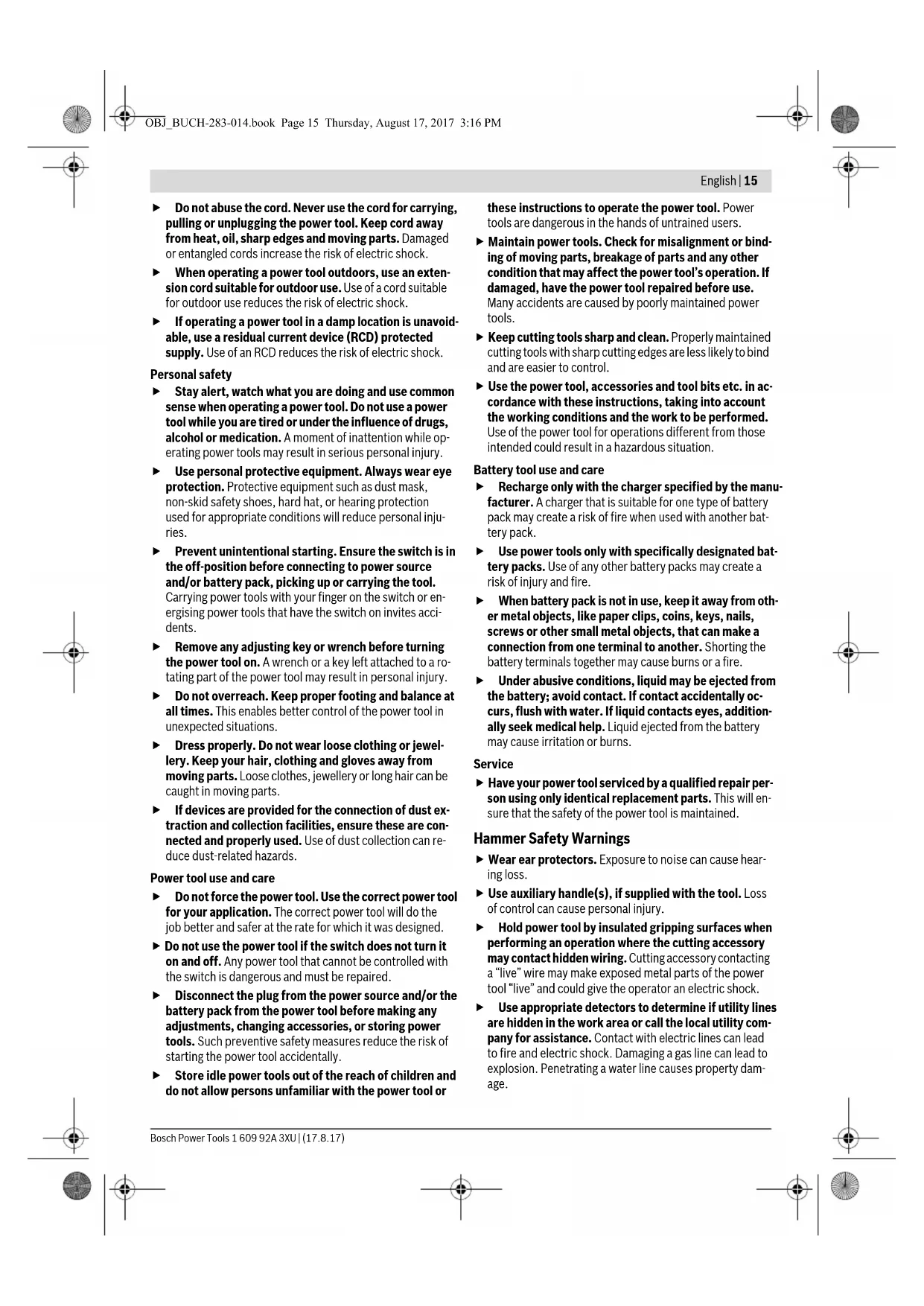
Product Description and Specifications

Read all safety warnings and all instructions. Failure to follow the warnings and instructions may result in electric shock, fire and/or serious injury.
While reading the operating instructions, unfold the graphics page for the machine and leave it open.
Intended Use
The machine is intended for hammer drilling in concrete, brick and stone, as well as for light chiselling work. It is also suitable for drilling without impact in wood, metal, ceramic and plastic. Machines with electronic control and right/left rotation are also suitable for screwdriving.
Product Features
The numbering of the product features refers to the illustration of the machine on the graphics page.
1 Quick change keyless chuck (GBH 36 VF-LI Plus)
2 SDS-plus quick change chuck (GBH 36 VF-LI Plus)
3 SDS-plus tool holder
4 Dust protection cap
5 Locking sleeve
6 Lock ring for rapid-change chuck (GBH 36 VF-LI Plus)
7 Vibration damper
8 Rotational direction switch
9 Handle (insulated gripping surface)
10 On/Off switch
11 Battery pack
12 Release button for mode selector switch
13 Mode selector switch
14 Worklight
15 Button for depth stop adjustment
16 Auxiliary handle (insulated gripping surface)
17 Depth stop
18 Battery unlocking button
19 Temperature control indicator
20 Battery charge-control indicator
21 Button for charge-control indicator
22 Securing screw for key type drill chuck (GBH 36 VF-LI Plus)
23 Key type drill chuck (GBH 36 VF-LI Plus)
24 SDS-plus adapter shank for drill chuck (GBH 36 VF-LI Plus)
25 Drill chuck mounting (GBH 36 VF-LI Plus)
26 Identification grooves
27 Chuck key (GBH 36 VF-LI Plus)
28 Front sleeve of the quick change keyless chuck (GBH 36 VF-LI Plus)
29 Retaining ring of the quick change keyless chuck (GBH 36 VF-LI Plus)
30 EPC switch (Electronic Precision Control)
31 Universal bit holder with SDS-plus shank*
*Accessories shown or described are not part of the standard delivery scope of the product. A complete overview of accessories can be found in our accessories program.
Noise/Vibration Information
Sound emission values determined according to EN 60745-2-6.
Typically the A-weighted noise levels of the product are: Sound pressure level 90 dB(A); sound power level 101dB(A). Uncertainty K = 3dB
Wear hearing protection!
Vibration total values a_h (triax vector sum) and uncertainty K determined according to EN 60745-2-6:
Hammer drilling into concrete: a_1 = 14.5 m/s, K = 1.5 m/s^2 Chiselling: a_b = 9.5 m/s^2, K = 1.5 m/s^2
Drilling into metal: a_h < 2.5m / s^2 K = 1.5m / s^2 Screwdriving without impact: a_h < 2.5m / s^2 K = 1.5m / s^2
The vibration level given in this information sheet has been measured in accordance with a standardised test given in EN 60745 and may be used to compare one tool with another. It may be used for a preliminary assessment of exposure. The declared vibration emission level represents the main applications of the tool. However if the tool is used for different applications, with different accessories or insertion tools or is poorly maintained, the vibration emission may differ. This may significantly increase the exposure level over the total working period.
An estimation of the level of exposure to vibration should also take into account the times when the tool is switched off or


English | 17
when it is running but not actually doing the job. This may significantly reduce the exposure level over the total working period.
Identify additional safety measures to protect the operator from the effects of vibration such as: maintain the tool and the accessories, keep the hands warm, organisation of work patterns.
Technical Data
| Rotary Hammer GBH 36 V-LI Plus GBH 36 VF-LI Plus | |||
| Article number | 3611 J06 0.. 3611 J07 0.. | ||
| Speed control | ● | ● | |
| Stop rotation | ● | ● | |
| Right/left rotation | ● | ● | |
| Quick change chuck | - ● | ||
| Rated voltage | V= 36 36 | ||
| Rated power input | W 600 600 | ||
| Impact rate | min-1 | 0-4200 | 0-4200 |
| Impact energy per stroke according to EPTA-Procedure 05/2009 J 3 | min-1 | 0-940 | 0-940 |
| - Left rotation | min-1 | 0-930 | 0-930 |
| Tool holder | SDS-plus | SDS-plus | |
| Spindle collar diameter | mm 50 50 | ||
| Drilling diameter, max.: | |||
| Concrete | mm | 28 | 28 |
| Brickwork (with core bit) | mm | 82 | 82 |
| Steel | mm | 13 | 13 |
| Wood | mm | 30 | 30 |
| Weight according to EPTA-Procedure 01:2014 | kg | 4.0/4.51) | 4.1/4.61) |
| Permitted ambient temperature | |||
| during charging | °C | 0...+45 | 0...+45 |
| during operation2) and during storage | °C | -20...+50 | -20...+50 |
| Recommended batteries | GBA 36V ... | GBA 36V ... | |
| Recommended chargers | AL36.. | AL36.. | |
| GAL 36.. | GAL 36.. | ||
1) depending on the battery pack being used
2) limited performance at temperatures < 0^
Technical data determined with battery from delivery scope.
Assembly
Battery Charging (see figure A)
Use only the battery chargers listed on the accessories page. Only these battery chargers are matched to the lithium-ion battery of your power tool.
Note: The battery supplied is partially charged. To ensure full capacity of the battery, completely charge the battery in the battery charger before using your power tool for the first time.
The lithium-ion battery can be charged at any time without reducing its service life. Interrupting the charging procedure does not damage the battery.
The lithium-ion battery is protected against deep discharging by the "Electronic Cell Protection (ECP)". When the battery is empty, the machine is switched off by means of a protective circuit: The inserted tool no longer rotates.
Do not continue to press the On/Off switch after the machine has been automatically switched off. The battery can be damaged.
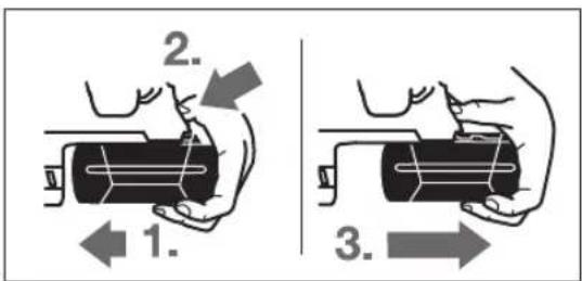
Removing the battery
The battery 11 is equipped with two locking levels that should prevent the battery from falling out when pushing the battery unlocking button 18 unintentionally. As long as the battery is inserted in the power tool, it is held in position by means of a spring.
18|English
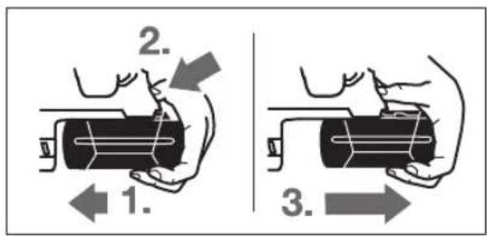
To remove the battery 11:
- Push the battery against the base of the power tool (1.) and at the same time press the battery unlocking button 18 (2.).
- Pull the battery out of the power tool until a red stripe becomes visible (3.).
- Press the battery unlocking button 18 again and pull out the battery completely.
Battery Charge-control Indication
The three green LEDs of the battery charge-control indicator 20 indicate the charge condition of the battery 11. For safety reasons, it is only possible to check the status of the charge condition when the machine is at a standstill.
- Push button 21 to indicate the charge condition (also possible when the battery is removed). The battery charge-control indicator automatically goes out after approx. 5 seconds.
LED Capacity
Continuous lighting 3 x green ≥ 2 / 3
Continuous lighting 2 x green ≥ 1 / 3
Continuous lighting 1 x green <1/3
Flashing light 1 x green Reserve
When no LED lights up after pushing button 21, then the battery is defective and must be replaced.
During the charging procedure, the three green LEDs light up one after the other and briefly go out. The battery is fully charged when the three green LEDs light up continuously. The three LEDs go out again approx. 5 minutes after the battery has been fully charged.
Auxiliary Handle
Operate your machine only with the auxiliary handle 16.
Changing the position of the auxiliary handle (see figure B)
The auxiliary handle 16 can be set to any position for a secure and low-fatigue working posture.
Turn the bottom part of the auxiliary handle 16 in counterclockwise direction and swivel the auxiliary handle 16 to the desired position. Then retighten the bottom part of the auxiliary handle 16 by turning in clockwise direction.
Pay attention that the clamping band of the auxiliary handle is positioned in the groove on the housing as intended for.
Selecting Drill Chucks and Tools
For hammer drilling and chiselling, SDS-plus tools are required that are inserted in the SDS-plus drill chuck.
For drilling without impact in wood, metal, ceramic and plastic as well as for screwdriving, tools without SDS-plus are used (e.g., drill bits with cylindrical shank). For these tools, a keyless chuck or a key type drill chuck are required.
Inserting/Removing the Key Type Drill Chuck (GBH 36 VF-LI Plus)
To work with tools without SDS-plus (e.g., drills with cylindrical shank), a suitable drill chuck must be mounted (key type drill chuck or keyless chuck, accessories).
Mounting the Key Type Drill Chuck (see figure C)
- Screw the SDS-plus adapter shank 24 into a key type drill chuck 23. Secure the key type drill chuck 23 with the securing screw 22. Please observe that the securing screw has a left-hand thread.
Inserting the Key Type Drill Chuck (see figure C)
- Clean the shank end of the adapter shank and apply a light coat of grease.
- Insert the key type drill chuck with the adapter shank into the tool holder with a turning motion until it automatically locks.
- Check the locking effect by pulling the key type drill chuck.
Removing the Key Type Drill Chuck
Push the locking sleeve 5 toward the rear and pull out the key type drill chuck 23.
Removing/Inserting the Quick Change Chuck (GBH 36 VF-LI Plus)
The SDS-plus quick change chuck 2 can easily be replaced against the quick change keyless chuck 1 provided.
Removing the Quick Change Chuck (see figure D)
Pull the lock ring for the quick change chuck 6 toward the rear, hold it in this position and pull off the SDS-plus quick change chuck 2 or the quick change keyless chuck 1 toward the front.
- After removing, protect the replacement chuck against contamination.
Inserting the Quick Change Chuck (see figure E)
- Use only model-specific original equipment and pay attention to the number of identification grooves 26. Only quick-change chucks with two or three identification grooves are permitted. When an unsuitable quick-change chuck is used, the application tool could fall out during operation.
- Before inserting, clean the quick change chuck and apply a light coat of grease to the shank end.
- Grasp the SDS-plus quick change chuck 2 or the quick change keyless chuck 1 completely with your hand. Slide the quick change chuck with a turning motion onto the drill chuck mounting 25 until a distinct latching noise is heard.
- The quick change chuck is automatically locked. Check the locking effect by pulling the quick change chuck.

English | 19
Changing the Tool
The dust protection cap 4 largely prevents the entry of drilling dust into the tool holder during operation. When inserting the tool, take care that the dust protection cap 4 is not damaged.
A damaged dust protection cap should be changed immediately. We recommend having this carried out by an after-sales service.
Changing the Tool (SDS-plus)
Inserting SDS-plus Drilling Tools (see figure F)
The SDS-plus drill chuck allows for simple and convenient changing of drilling tools without the use of additional tools.
-
GBH 36 VF-LI Plus: Insert the SDS-plus quick change chuck 2.
-
Clean and lightly grease the shank end of the tool.
-
Insert the tool in a twisting manner into the tool holder until it latches itself.
-
Check the latching by pulling the tool.
As a requirement of the system, the SDS-plus drilling tool can move freely. This causes a certain radial run-out at no-load, which has no effect on the accuracy of the drill hole, as the drill bit centres itself upon drilling.
Removing SDS-plus Drilling Tools (see figure G)
- Push back the locking sleeve 5 and remove the tool.
Changing the Tool (without SDS-plus) (GBH 36 VF-LIPlus)
Inserting (see figure H)
Note: Do not use tools without SDS-plus for hammer drilling or chiselling! Tools without SDS-plus and their drill chucks are damaged by hammer drilling or chiselling.
- Insert a key type drill chuck 23 (see "Inserting/Removing the Key Type Drill Chuck", page 18).
- Open the key type drill chuck 23 by turning until the tool can be inserted. Insert the tool.
- Insert the chuck key into the corresponding holes of the key type drill chuck 23 and clamp the tool uniformly.
- Turn the mode selector switch 13 to the "drilling" position.
Removing (see figure 1)
- Turn the sleeve of the key type drill chuck 23 with the drill chuck key in anticlockwise direction until the drilling tool can be removed.
Changing the Tool (without SDS-plus) (GBH 36 VF-LIPlus)
Inserting (see figure J)
Note: Do not use tools without SDS-plus for hammer drilling or chiselling! Tools without SDS-plus and their drill chucks are damaged by hammer drilling or chiselling.
- Insert the quick change keyless chuck 1.
-
Firmly hold the retaining ring 29 of the quick change chuck. Open the tool holder by turning the front sleeve 28 until the tool can be inserted. Tightly hold the retaining ring 29 and firmly turn the front sleeve 28 in the direction of the arrow until a distinct latching noise can be heard.
-
Check the tight seating by pulling the tool.
Note: If the tool holder was opened to the stop, then the latching noise possibly may be heard while closing the tool holder and the tool holder will not close.
In this case, turn the front sleeve 28 once in the opposite direction of the arrow. Afterwards, the tool holder can be closed (tightened) again.
- Turn the mode selector switch 13 to the "drilling" position.
Removing (see figure K)
- Firmly hold the retaining ring 29 of the quick change chuck. Open the tool holder by turning the front sleeve 28 in the direction of the arrow until the tool can be removed.
Dust Extraction with GDE 16 Plus (Accessory)
Dust from materials such as lead-containing coatings, some wood types, minerals and metal can be harmful to one's health. Touching or breathing-in the dust can cause allergic reactions and/or lead to respiratory infections of the user or bystanders.
Certain dust, such as oak or beech dust, is considered carcinogenic, especially in connection with wood-treatment additives (chromate, wood preservative). Materials containing asbestos may only be worked by specialists.
-As far as possible, use a dust extraction system suitable for the material.
- Provide for good ventilation of the working place.
- It is recommended to wear a P2 filter-class respirator.
Observe the relevant regulations in your country for the materials to be worked.
Prevent dust accumulation at the workplace. Dust can easily ignite.
A GDE 16 Plus (accessory) is required for dust extraction. The vacuum cleaner must be suitable for the material being worked.
When vacuuming dry dust that is especially detrimental to health or carcinogenic, use a special vacuum cleaner.
Operation
Starting Operation
Inserting the battery
- Set the rotational direction switch 8 to the centre position to protect the power tool against accidental starting.
- Insert the charged battery pack 11 from the rear into the base of the power tool. Press the battery pack completely into the base until the red stripe can no longer be seen and the battery pack is securely locked.
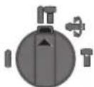
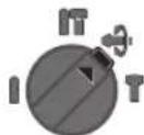
Setting the operating mode
The operating mode of the power tool is selected with the mode selector switch 13.
Note: Change the operating mode only when the machine is switched off! Otherwise, the machine can be damaged.
- To change the operating mode, push the release button 12 and turn the mode selector switch 13 to the requested position until it can be heard to latch.


20|English
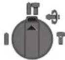
Position for hammer drilling in concrete or stone
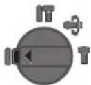
Position for drilling without impact in wood, metal, ceramic and plastic as well as for screwdriving
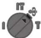
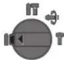
Vario-Lock position for adjustment of the chiselling position
The mode selector switch 13 does not latch in this position.
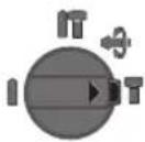
Position for chiselling
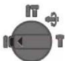
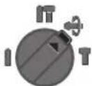
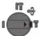
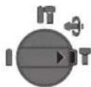
Reversing the rotational direction
The rotational direction switch 8 is used to reverse the rotational direction of the machine. However, this is not possible with the On/Off switch 10 actuated.
Right rotation: Move the rotational direction switch 8 all the way to position
Left rotation: Move the rotational direction switch 8 all the way to position
Set the direction of rotation for hammer drilling, drilling and chiselling always to right rotation.
Switching On and Off
To save energy, only switch the power tool on when using it.
To start the machine, press the On/Off switch 10.
When starting the machine for the first time, a starting delay is possible, as the electronic system of the power tool has to configure itself first.
- To switch off the machine, release the On/Off switch 10.
Setting the Speed/Impact Rate
The speed/impact rate of the switched on power tool can be variably adjusted, depending on how far the On/Off switch 10 is pressed.
Light pressure on the On/Off switch 10 results in low speed/impact rate. Further pressure on the switch increases the speed/impact rate.
Electronic Precision Control (EPC) (see figure L)
EPC assists you when working with impact in sensitive materials by ensuring slow start-up and reduced operating speed.
- Slide the EPC switch 30 to the desired position.

Position for maximum operating speed

Position for slow start-up and reduced operating speed
Overload Clutch
If the tool insert becomes caught or jammed, the drive to the drill spindle is interrupted. Because of the forces that occur, always hold the power tool firmly with both hands and provide for a secure stance.
If the power tool jams, switch the machine off and loosen the tool insert. When switching the machine on with the drilling tool jammed, high reaction torques can occur.
Rapid Shut-off (Kickback Control)
The rapid shut-off feature (KickBack Control) provides better control over the power tool. The power tool will switch off if it suddenly and unforeseeably rotates around the drilling axis.
- To restart the machine, release the On/Off switch and then actuate again.
Rapid shut-off is indicated by flashing of the worklight 14 on the power tool.
Rapid shut-off can trigger only when the power tool is running at maximum operating speed and can rotate freely around the drilling axis.
Temperature Control Indicator
The red LED of the temperature control indicator 19 signals that the battery or the electronics of the power tool (when the battery is inserted) are not within the optimum temperature range. In this case, the power tool will not operate at full capacity.
Temperature control of the battery:
- The red LED 19 lights up continuously after inserting the battery into the charger: The battery is not within the charging temperature range between 0^ and 45^ and cannot be charged.
- The re19 flashes when you press the 21 button or the On/Off switch 10 (with battery inserted): The battery is outside of the permitted operating temperature range.
- For battery temperatures over 70^ , the power tool switches off until the battery is in the optimal temperature range again.
Temperature control of the power tool electronics:
- The red LED 19 lights up continuously when pressing the On/Off switch 10: The temperature of the machine's electronics is below 5^ or above 75^ .
- At a temperature above 90^ , the electronics of the power tool switch off until the temperature is within the allowable temperature range again.
Working Advice
Adjusting the Drilling Depth (seefigure M)
The required drilling depth X can be set with the depth stop 17.
- Press the button for the depth stop adjustment 15 and insert the depth stop into the auxiliary handle 16.
English | 21
The knurled surface of the depth stop 17 must face downward.
- Insert the SDS-plus drilling tool to the stop into the SDS-plus tool holder 3. Otherwise, the movability of the SDS-plus drilling tool can lead to incorrect adjustment of the drilling depth.
- Pull out the depth stop until the distance between the tip of the drill bit and the tip of the depth stop corresponds with the desired drilling depth X .
Changing the Chiselling Position (Vario-Lock)
The chisel can be locked in 36 positions. In this manner, the optimum working position can be set for each application.
- Insert the chisel into the tool holder.
- Turn the mode selector switch 13 to the "Vario-Lock" position (see "Setting the operating mode", page 19).
- Turn the tool holder to the desired chiselling position.
- Turn the mode selector switch 13 to the "chiselling" position. The tool holder is now locked.
- For chiselling, set the rotation direction to right rotation.
Inserting Screwdriver Bits (see figure N)
Apply the power tool to the screw/nut only when it is switched off. Rotating tool inserts can slip off.
To work with screwdriver bits, a universal bit holder 31 with SDS-plus shank (accessory) is required.
- Clean the shank end of the adapter shank and apply a light coat of grease.
- Insert the universal bit holder with a turning motion into the tool holder until it automatically locks.
- Check the locking effect by pulling the universal bit holder.
- Insert a screwdriver bit into the universal bit holder. Use only screwdriver bits that match the screw head.
- To remove the universal bit holder, pull the locking sleeve 5 toward the rear and remove the universal bit holder 31 out of the tool holder.
Vibration Damper
Vibration
The integrated vibration damper reduces occurring vibrations.
The soft grip handle increases the safety against slipping off and thus provides for a better grip and handling of the power tool.
Recommendations for Optimal Handling of the Battery
Protect the battery against moisture and water.
Store the battery only within a temperature range between -20^ and 50^ . As an example, do not leave the battery in the car in summer.
Occasionally clean the venting slots of the battery using a soft, clean and dry brush.
A significantly reduced working period after charging indicates that the battery is used and must be replaced.
Observe the notes for disposal.
Maintenance and Service
Maintenance and Cleaning
Before any work on the machine itself (e.g. maintenance, tool change, etc.) as well as during transport and storage, remove the battery from the power tool. There is danger of injury when unintentionally actuating the On/Off switch.
For safe and proper working, always keep the machine and ventilation slots clean.
A damaged dust protection cap should be changed immediately. We recommend having this carried out by an after-sales service.
- Clean the tool holder 3 each time after using.
After-sales Service and Application Service
Our after-sales service responds to your questions concerning maintenance and repair of your product as well as spare parts. Exploded views and information on spare parts can also be found under:
www.bosch-pt.com
Bosch's application service team will gladly answer questions concerning our products and their accessories.
In all correspondence and spare parts orders, please always include the 10-digit article number given on the nameplate of the product.
Great Britain
Robert Bosch Ltd. (B.S.C.)
P.O.Box 98
Broadwater Park
North Orbital Road
Denham
Uxbridge
UB95HJ
At www.bosch-pt.co.uk you can order spare parts or arrange the collection of a product in need of servicing or repair.
Tel. Service: (0344) 7360109
E-Mail: boschservicecentre@bosch.com
Ireland
Origo Ltd.
Unit 23 Magna Drive
Magna Business Park
City West
Dublin 24
Tel. Service: (01) 4666700
Fax: (01) 4666888
Australia, New Zealand and Pacific Islands
Robert Bosch Australia Pty. Ltd.
Power Tools
Locked Bag 66
Clayton South VIC 3169
Customer Contact Center
Inside Australia:
Phone: (01300) 307044
Fax: (01300) 307045


22 | Français
Inside New Zealand:
Phone: (0800) 543353
Fax: (0800) 428570
Outside AU and NZ:
Phone: +61 395415555
www.bosch-pt.com.au
www.bosch-pt.co.nz
Republic of South Africa
Customer service
Hotline: (011) 6519600
Gauteng - BSC Service Centre
35 Roper Street, New Centre
Johannesburg
Tel.: (011) 4939375
Fax: (011) 4930126
E-Mail: bsctools@icon.co.za
KZN - BSC Service Centre
Unit E, Almar Centre
143 Crompton Street
Pinetown
Tel.: (031) 7012120
Fax: (031) 7012446
E-Mail: bsc.dur@za.bosch.com
Western Cape - BSC Service Centre
Democracy Way, Prosperity Park
Milnerton
Tel.: (021) 5512577
Fax: (021) 5513223
E-Mail: bsc@zsd.co.za
Bosch Headquarters
Midrand, Gauteng
Tel.: (011) 6519600
Fax: (011) 6519880
E-Mail: rbsa-hq.pts@za.bosch.com
Transport
The contained lithium-ion batteries are subject to the Dangerous Goods Legislation requirements. The user can transport the batteries by road without further requirements.
When being transported by third parties (e.g.: air transport or forwarding agency), special requirements on packaging and labelling must be observed. For preparation of the item being shipped, consulting an expert for hazardous material is required.
Dispatch batteries only when the housing is undamaged. Tape or mask off open contacts and pack up the battery in such a manner that it cannot move around in the packaging. Please also observe possibly more detailed national regulations.
Disposal

The machine, rechargeable batteries, accessories and packaging should be sorted for environmental-friendly recycling.

Do not dispose of power tools and batteries/re-chargeable batteries into household waste!
Only for EC countries:
According to the European Guideline 2012/19/EU, power tools that are no longer usable, and according to the European Guideline 2006/66/EC, defective or used battery packs/batteries, must be collected separately and disposed of in an environmentally correct manner.
Batteries no longer suitable for use can be directly returned at:
Great Britain
Robert Bosch Ltd. (B.S.C.)
P.O.Box 98
Broadwater Park
North Orbital Road
Denham
Uxbridge
UB95HJ
At www.bosch-pt.co.uk you can order spare parts or arrange the collection of a product in need of servicing or repair.
Tel. Service: (0344) 7360109
E-Mail: boschservicecentre@bosch.com
Battery packs/batteries:
Li-ion:
Please observe the instructions in section "Transport", page 22.
Subject to change without notice.
Français
Colocar o accumulator
Boring metal: a_1 < 2,5m / s,K = 1,5m / s^2
Skrue: a_h < 2,5m / s^2,K = 1,5m / s^2
Bosch Service Center
Telegrafvej 3
2750 Ballerup
Pá www.bosch-pt.dkk kander online bestilles reservedele erer oprettes en reparations ordre.
TIf. Service Center: 44898855
Fax: 44898755
E-Mail: vaerktoej@dk.bosch.com
Transport
Bosch Service Center
Telegrafvej 3
2750 Ballerup
Danmark
Tel.: (08) 7501820 (inom Sverige)
Fax: (011) 187691
Transport
De litiumjonbatterier som ingar ar underkastade kraven for farligt gods. Anvandaren kan utan ytterligare forplichtelser transportera batterierna pa allman vag.
Apaipceon rou ypavacwou took
TOnoBcHnTou TcK (βaene EikovaE)
Na xpnoumonoietepoovvnoiaeapntmuata,katalaa yia to ekaoote ovo telo, kai va divete npoooy n otov apio twavaulakowew avaywopionc 26. Etnpenetai povo ngpiontook me duo n tpeic aulakoeic avaywopionc. Zepinwnnou sto epyaaleio auto ta tonothetaei eva akatalantook, tote to tonothetaevo epyaoleio mopei, kata tn diapkeia tnc aeitoupyiac, vataxte iEw.
- Na kaθaipizete To Took npiv To TonoθeTHaete Ka va λιαilvete ελαρpà To οτελεχος Tou.
-uykpatnote kaiae oolokanpo to xepi aoc to took SDSplus 2, avaloya, to taxutook 1. Pepate to took me nepitopoehn enavw otny unobooh Tou Tock 25,exvi vaakouoe te kaqap aty vadalwae.
-To taok paVaalawve autopata. ELeyTe Tn pavdaawon me TaBnya tou took.
EAnvikd101
Avtikataaon epyaleiou
To kαλμμa npoσaioac and oκovn 4 εμnoδiει kavonotntika Tn δieioδuωn oκovnc trpunhμatoc σην unobox έργαεloi kata Tn diapkeia nca leitoupyiac. 'Oτav tonoθeite to eργαεio πεπει va npoexetε, va μην unοσει βλαβη to kαλμμa npoσaioic a and oκovn 4.
EvXaAaevoKaAmu npoataoc ao kovnpene vaavtkaiotatauoeoc.aaoubououc,navtkarataanva biedayetaranto Service.
Avrakadotaon cpyaleiou (SDS-plus)
TOnoTeHnO npyaleiou SDS-plus (Blece cokova F)
Me to taok SDS-plus nopeire va aaaaeteto tonoetnevo epyaleo ana kai dveTa, xwpic va xnpoionoiote aaepyaleia.
- GBH 36 VF-LI Plus: Tonoθετησε Φ to ΣoK SDS-plus 2.
KaapieTe kai alalveTe eapdTo oTeXoc Tou epyaleiou.
TOnoTeHnETo epyaleio OtvuOdoxh epyaleiou yupIOVrAcTo pExiVa paVaalwaeI ano mvo Tou.
TpaBnEToepyaleoiavaeEyEETn paVbAwn.
To epyaleio SDS-plus eleuethetaepa kivnto. Eto, otny nepiotpophxwpic optio, to tpuanvi dev npiotpepeta akipicuukia. Auto, omuoc, dev embp a onv akipieia trunmuatoc enetn to tpuanvi autokevtpapetal.
Apaiaeon epyaieiou SDS-plus (Blambda eukova G)
Apaieon tou epyaIeou (Bte eKova I)
-ΓupiTe μe To KλeBi Tou To KλuPoC Tou γpavacwToouk 23μe φopá avTθeTn Tc ρoλoayaknc, μexpi va μnpoeσeτe va apaipéoTe To TOnOeTneV eργaλeio.
Avtikarataon epyaaleiou (xomega SDS-plus) (GBH 36 VF-LIplus)
Tonoettnon twv epyaieiw (baene ekova J)
YnodEgN: Mn xnpaonouhoTe nore epyaiaeia xwpi cSDS-plus ia trpunmae Kpoan nyia kalemuia! Ta epyaiaea wipic
SDS-plus kai ta avtroia Taok kataotpeovtai otav xnooioouvai Tpumnae Kpoonkai ykaalemuqa.
- TOnoθετηθετο TαxutooK 1.
- Suykpatnate yepa to daKTuio ouykpatnoq 29 Toa Tuok.AvoIETe Tnv unooyn epyaieou yupicovtao to npooTIO vo daKTuio 28 mexvi maopoeaeve to tonoetnoe to epyaleio. Suykpatnote kala to daKTuio ouykpatnoq 29 KaYupiote yepa to npootivo kelaupoc 28 onw dcixwei to uBoLo mexvi akouete kaOap a evo opubo kaotaviaq.
Eλeγξετημανδαλωσημετραβηγμaιού εγαλειου.
Ynodex: Zepinwn nou n unofox npyaaleiou dvoE tepa Tote, otav yupizetny unofox npyaaleiou ia va kaleei, o 0pucoc kaotaviauc npoei va akouyetai, xwic va kaleivei n unofox npyaaleiou.
SemuTeoia nepiTwn yupite iaopa tnu unodoxn epyaaleou 28 ieopa avtiognt an ao nou deixvei to baooc.AkoAouwuc npoeite va kelaote tnnu unodoxn epyaaleou.
-Γuipote To diaokottnavaotoanc kpooong/npoiotpooic 13
Otn θeon «Tpunma.
Apaieon Tou epyaaleiou (bene cukova K)
Σuykpatnote yepa to daKTuio ouykpatnnc 29 tou tauxoK.AvoIeTnv unOdox np epyaleiou upovtaoc to mpootv o Kauoc 28 popa iia paun nou deiyvei to bao, expa va npopeoetva apapeoetto epyaio.
Avappopnoan oKovnc mc to GDE 16 Plus (eIdeltao eaptnma)
Koepa eon Eou, an oopka kai an petaa a npoe va elav avuyieivn. H enp n t kn iion von tnc npoe va npokalae aalepyikc avnpaeic n /kai aooteiec tov avanveotikov odov tou xphtn tuXov napepuokouevw arouv.
Oipaeva eio nokvnc, n. x. kovn ano Eul oElambdaic n Oiaac 0eowpuvtai av Kapkiyoova, iiaitepa oe uovduaog o e diaopopa aupnnpwpatika uiknou npaonoiuvtai otny katepyaia Euawv (evwoecxpwliou, EuonpoataTeutika paa). H katepyaia qauvtouxwv uukw enipteteta mvo oe iiedka eknaidemuva atota.
Na xpnaiomoiite kata to duvato yia to ekaoTote uiko Tny katalnnan avappopnan.
- Na φροντιζε τγία τοῦ καλό αεριμό του χώρου εργαδις.
-2aououououevo opate paokec avanveoTiknpootaiac me pIATPO karyopyiac P2.
Na TnpieTic diataeic nou IOxouov OTn Xwpa oac yia Ta 61- a4opa uno katepyaia uikia.
Na anopeuyete n 8nuioupyia ouoowpeunoc okovnc 10x wpo nou epyzote. Okovec avapheyovtai eukola
Tn avappopnon nC akovnc anaateir at eva GDE 16 Plus (eaptnma).
O anoppoqnTnpa oKovnc npene va eivat kataaAioyia to ekaoTote unkatepyaia uiko.
Tn avapoppon 1iaitepa avouieivnc, kapiovoyovou n E npoc o Kovnc npene va xpnoaonoei te etikouc anoppopntpe cokovnc.

102|EALnyiuka
Aeitoupyia
Ekkivnon
Tonoetnon tnc matapiac
Tia nV npoTaia Tou nAekpikou epyaleoi anTo tvov aTheeIaTn ekivnon va yupizete To diakottn aalaync opac nepOtoopc8 otuaia oen.
Eioayet n oopitouevn unatapia 11 oto neu taou nektorkou cypaleiou ano to niow epcoc. Pntote nnu unatapia Tepua meoa oTo nela, mexi va epaaviotei n kokivn awpi-6a ka va aopaioei npwoe n unatapia.
Pouon Tou poun auToupylac
Me To diaoknnaavaoanKpouanc/neipotpohc13 emeYete Tov pono aeitoupyiaoc Tou nAekptikou epyaleiou.
YnodcEg:Na aaaaTe TO TPO ANeIoupyiac MOVOTAVTO nAekTpiK epyaaleo Bioketat EKToc AteuOpyiac! DIAqopetikaTo nAekTpiK epyaaleio mopei va unotei Zmuia.
Tva aaAaeTe Tov Tpno aeIoupyiac natote To koupi anopavdaawonc 12 kai yupiote to diakontn avaotoankpooanc/neipatopnpnc 13 onv enuunr theon, pexpa va akouoete ot paovdaowae.
Oeon yia Tpumma e Kpuoan ae nntov n ne-tpua
OeON yia Tpumna xwoic kpoouon oe Eua, me Taalaa kai OE kepauiKa kai naoTikkaAikKa- 0wKai yia biDomegaata
Oeon Vario-Lock yia puthetaion tnc thec kalemuatoc
EaunTnOdiakomncavaotolkpoouon/epiopp136evavdaawvei.
Oeanyia kalemuopa
SigmaKntn UeepoPtoNc
Se nepiwn nou to eaptna opnywoei npookpouo i kənou, diakonteta n petoadoon kivnonc stov aOva. Na kparate, loyw twv epaaviopeevwduvaewv, to nAekpiok epyaaleio ka la ke ta duo oac xepia kal v nalpvete to owa aoc oraeeph otao.
Otav mIoKapTe to nAeKtpko epyaleo theTo ekTc Aeioupyia kai auote to tonoetnevo epyaleio. O'otav 0eOte to nAeKtpko epyaleio ae IaIoupyia me nAoKapuaevo to epyaleio tpuHmuatoc dnoupyovtai axupec avtbpatake cduvaeic (kAoToHmuata).
Taxeia diaconi IeIoupyiac (Kickback Control)
H ynpoyananevepyoioian (Kickback Control) npoeppei evav kautepe oLeyo tou nAekptikou epyaieou. Se nepintwn EapvkiKa anpoblaennc neipotpooc Tou nAekptikou epya leiou upw anotov dova Tou tpanaviou anevepyoioietal to nAekptiko epyaieio.
- Tia nTv enavekkvnon apnoTe to biakomtn ON/OFF ekeuθepo kai akolouwcnatneToTov ek vou.
H yprnoanepepyoioi npaovicietai pe to avaobnau Tou otoe pyaiaic 14 0to nektpko epyaio.
EAnvikd103
H yipoyop anevpyooinan opei va evpyoointheta i mvo,otav tonkptko epaaleo letoupye ie to meyto apioo otropov epyaiaac ka npoei va nepiota pphi eueepa ypuo and tov aOva toupunaviou.
EvEiyniaeinnnoon0epoKpaoic
H KOKIVn ofoBDIOOC vT nV evBEn en ttnponnc Tc eepoKpaiaac 19 onpatodotei ot n unatapia n to nektpovko ouotna Tou nekptikou epyaleiou (otav n unatapia elvai tonoetneyn) dev piokovtaeaa atny apoiin nepiox. ^ autny tvnpintwn to nekptikoepyaleio etre dev epyazeta ka0lou ete eyzctae iepeiwevn lou.
Emnpnon nC 8epuokpaac tnc matapac:
'Otav n Kokkivn foTobodoc 19 avabei diapKc uicu n npatapia tonoBctnei oto nAektpko epyaIe: H npatapia Bpoketai eEw ano Tnv nepoxh opotionc metaE0C kai 45 C kai y auto dev npopei va qopntei.
H KOKKIVN φWTOBIOBOc (LED) 19avaBoaBHyveIeTo natoTnau Tou nKnTPOU 21 n Tou diakomn On/Off 10 (oe nepimwn ToOnoetneVNC matapiaC): H matapia eival ktroctncpePoxnc TNC eepokpaiaac aeoupyiac.
-Orav n 0epuokpaia unepei touc 70^ toTe nektpiko epaalei diaoknte i autouata n letroupyia tou mepoi npatia va enaveoetn kavovikn nepioxh 0epuokpaiaac.
EtnipnOeepokpaiaocou nAektpovikou ouotmuatocou nAekptikou epyaieiou:
-H Kokkivn pWtoBIOOc 19 avabei diapKoc otav natneol o diaKoTNC ON/OFF 10: H eepuokpaoia tnc nkekpoviknc Tou nkeptikou epyaieou evai kpoTepn ano 5^ n peya- Lutepn ano 75^
-OTAV n Θεροκρασia Επεραει touc 90°C to Μλεκτρονικό Μαιŋμa Tou nλεκτρικού εργαλειou diakοίτι autóμata nλειούργια Tou μεχριθεροκρασia va επιοτρέψει náλι στην εγκεριφένη περοχή Θεροκρασίας λειούργιας.
YnobeiEic epyaiaac
Poumuonbaouocptummuoc(βaeneukovaM)
MeTovobnyoBaouc17muopeiteva puthetaaeTo emuunto Baooc Tpuetaoc X.
Euvtnpnon kal Service
UvtipnKaKaBapiooC
Apaieire nV npatapia ano tonkpiok epyaleio npv ano onoiabhote epyaia oto idio tonkpiok epyaleo (n.x. ouvtipnon, aalayn epyaleiou kT.) kaowc kal kata nV metapopao tou kal ndiapuaen/tnv
104 | Türkce
Surekli isk 1 x yesil <1/3
Yanip sönen isik 1 x yesil Rezerve
Robert Bosch Sp. z o.o.
BSC
Ul. Szyszkowa 35/37
02-285 Warszawa
Bosch Service Center PT
K Vapence 1621/16
692 01 Mikulov

Slovensky | 129
IcnoIb3oBaHHoe B HAcTOnuHnHCTpyKunx uYka3aHHx NOHTHE 3NEKTPOHNCHPTpMeHrPacnpocptpaHraTc Ha 3eKTPOHNCHPTpMeHrC nITaHnEM OT cTeH (c ceTeBbIM shypom) Ha aKKyMnAToPbH b3eKTPOHNCHPTpMeHr (6e3 ceTeBoro shhya).
Be3onacnoctb pa6oery mecta
CoepKHe pa6ooye MeTo B HcTe H XopoOo OceE HeHbM. BecnpaIOk Hn HeOcBeIeHHbIe yAcTKn pa6oeryo MeTa MOrYt PnBecTn K HeCuaCTHbIM CnyaAM.
He pa6oTaIe c 3THM 3NEKtpOHCTpyMeHOTm BO B3pblBOONaCHOM NOMEUeHHN, B KOTOPOM HAXOJrTcR TOpOHyE XIKKOCTH, BOCnPAMEHIOUeCe Ra3bI HIN PbIb.3NEKtpOHCTpyMeHTbI HCKPAT, YTO MOXET PnIBEcTn K BOCnPAMEHeHIO PbIIN IIN NapOB.
Bo Bpempa60bIc3neKtpOHnHCTpyMeHTOM He donyckaTe 6n3ko Baewemy pa6oemy meTy deten H noctopoHHx nU. OTBleKwncb, Bbl MoKeTe NoTepeTb KOHTPOJIb HAD 3neKTPOHnHCTpyMeHTOM.
3NeKtpo6e3onacHocTB
Wtencbna Bnka 3eKtpOnHcTpymeta Donxha noDxOHTB K WtencbHO pO3ETke. Hn B KOem cnyae He N3MeHnTe WtencbHyIO Bnky. He npMehnIe nepexoHbIe WtKepebln 3eKtpOnHcTpymetOB C 3aunTHbIM 3a3emHeHm. Hen3MeHeHHble WtencbHbIe BnIKN I NOxOJUe WtEncbHbIe PO3ETKN CHN KaOT PnCK IopAkeHn 3eKTPOTOKOM.
PpeoTbpaaTe TeneChbKOHTc3a3eMHeHHbIMN NOBepxHocTAMKAKTO:CTpy6amn,3neMeHTAMNOTONNEHHKyXOHbIMN NITAMN XOJODHBHKaAMN.Pp3a3eMHeHHBaWero Tena nobbiwaetc npck nopaxehnaEJIeKTPOtOKOM.
3aunuatae 3neKtpOHCTpyMeHOTdoxNc bipocn. POnHHOBHeBn BOdb B3neKtpOHCTpyMeH TNOBbIaet PnCK nopaKeHn 3neKtpOTOKOM.
He pa3pe7aetcHcNoIb30BaTb shyP He noHa3haeHHIO, HApnMep, IIn TpaHCnOpTnPOBKn HIN NOBeCKN 3NEKTPoHNCTpyMeHTA, HIN Dn BbITrABHnBnBnKN H3 WTeNCbHo pO3eTK. 3auuMaIte wHyp ot BO3dECTBn BBICOKHX TEMpeaTp, Macna, OcTpbIX KpOMOK HIN NIOBbXhix qacte 3NEKTPoHNCTpyMeHTA. NOBpeJxHbHm HIN CNYTaHHbI shyP NOBbIaET PnCK nopaxEHn 3NEKTPoTOKOM.
Pn pa6ote c 3neKtponHcTpyMeHToM nO dOKpbItbIM He6om npmehaTe nprohdhe Ira 3TOr Ka6enn-ydnnHHTeIN. PpmeHHe nproHOro Ira pa60I nO d
KpbTbIM He6OM Ka6eIyDINHHTeIa CHNkaET Pnck npaKeHHA 3NEKTPOTOKOM.
EcnH HeBO3MOXHO 36ExKaTb PnHMeHeHH 3NeKTPoHNCTPymEtA B CbIpOM NOMEuEHNN, NOkKnIOaHTe 3NeKTPoHNCTpymENT Ype3 yctPoNcTBO 3auNTHOrO OTKnIOueHH. PnHMeHeHH yCTpoNcTBa 3aunTHOrO OTKnIOueHH CHNkaet PNCK 3NeKTPuueckCOro NopaxHeHH.
Be3oNaChocbIIODei
BybTe BHNMaTeNbHbIMn, CneIte 3a TeM, yTo BbI deNaete, nPpOyMaHHO hauHnaite pa60Ty c 3NeKtpoHnCTpyMeHTOM. He NOnb3yIeTcB 3NeKtpoHnCTpyMeHTOM bYctanOM coCToHHN Hnn ecHbI hAxoJIteCb BcoCToHHN HApKOthueCKTO Hn AnKOrONbHorO onbA Henn HnN NOB Bo3dEChTBHeNem neKapCTB. OINH MOMENT HeBHMaTeNbHocTH npn pa60Te C 3NeKtpoHnCTpyMeHTOM MOKeT pNBecTn K cepbe3HbIM TpaBMam.
PpHMeHHeTe CpeCTBa HnHbNHyaNbHo3aunTbH BcERda 3aunThbIe OcKn. NcNoJIb3ObaHne CpeCTB INHINBnDyAIBHO 3aunTbI, KaK To: 3aunTHoM MaCKn, O6yBNHaHECKOJIb3RJeuN NOOUIBE, 3aunTHOrO IJNeMa HIN CpeCTB 3aunTbI opraHOB CnyxA, -B 3aBNCIMocTN OT BnJa pa60TbIC 3JIeKTPOINHCTpyMeHToM CHNXaET PnCK NOnyuHnTPaBM.
PpeoTbpaaaTe HnpeHaMepeHHe BKnOueHne 3NeKtpOnHCTpyMeHTa. NpeD noKnIOueHem 3NeKtpOnHCTpyMeHTa K 3NeKtpOnHtAHNo/HnN KaKKMyIyTOpy y6eNTecb BBkIOueHHOM CoCTOHNN 3NeKtpOnHCTpyMeHTa.YepKaHne NaBua Ha BbIKIOUcATEnp INTPaHCnOpTnPOBKe 3NeKtpOnHCTpyMeHTa NnoKIOueHHe K CETN PNTaHNR BKNIOueHHOr O 3NeKtpOnHCTpyMeHTa YpeBaTO HeCuaTHbIMn CnyaAMN.
y6paTe yCTaHOBChH HnCTpyMeH nHraeHbE KIOuN DO BKNIOUeHHN 3NEKTPoHNCTpyMeHT. INCTpyMeHT NNI KIOU, HAXOJUINC RBO BpaAIOUeCRAcTHN 3NEKTPoHNCTpyMeHT, MOXET PnPBecTn KTPaBMam.
He npHHMaIte HeecTeBcHHOe NOXKeHne KOpnyCa TeJa. Bcerda 3aHHMaIte yctOuHBOe NOXKeHne H coXpaHnIte paBHOBeCne. BnaIgApA 3tOMy Bbl MoKTe LyUWe KOHTpONIpOBaTb 3NeKTPOINHCTpyMeHT B HeOxNdaH HbIX CNTyaUNX.
Hocnte noxoadyipo paoyuyo oexdy. He hochte shpokyo odexky H ykpaewn. Depknte BONOCbl, odexdy npykabnblBdann OT DnNkxyuXncs qactei. lnpokay oedka, ykpaewn Hn nnDnHHbE BONOCbl MOrTy 6bTb 3aTHyTb BpaauOHmncr qactAMn.
PnHaHnHHBO3MOXHOCTN yCTaHOBKN PbIeOTcAbBaHOuHx NbIeNC6OpbIX yCTpOCTNBPOBepRte HNPcOeHNHeHne HnpABUNbHOe NCNOB3OBAHNE.PnMeHHeNPe PbIEOTCocMAoKet CHN3HTb ONaCHOCTb, CO3DaBaemyIO PbIbIO.
BHIMAHHE! B clyuea BO3HKnHOBeHHn nepe6oB pa-60te 3neKtpOnHcTpymEnTa BCNeCTBHe NOHOrO Hnn qactmHoro npeKpaueHHn 3HeproChAsKHeHHn NnnoBpexDeHHn cENynpAbeHHn 3HeproChAsKHeHHem yctahOBHTe BbIKNoUaTeNb B noJooKeHHe Bblk.,y6eHNBWHsc, yTO OH He 3a6NOKpOBaH (npH erO HanuHH). OTKIOHTe cTeByIO Bnky OTpo3ETKNn OTcoEHHN
148 | Pycsckn
Te cBemHbI aKkymyTOp.3TMM npeoTbpaaetcHKeKOHToPnPyEmbIOBtOpHb3aNyck.
PpHMeHHeH 3JekTpOHHCTpyMeHTa H6paUeHNc HMM
He neperpykaTe 3neKtpOHCTpymENT. HcnoIb3yTe DnBaWe pa60TbI npedHa3NaueHHbI dna 3ToR 3neKtpOHCTpymENT.C nOxOJaIM 3neKtpOHCTpyMeHTOM Bby pa60TaTe lyuwe n HaedJHee B yka3aHHom DnApa3OHe MOUHOCTn.
He pa6oTaIe c 3neKtpOnHcTppyMeHTOM npn HEnCnpaB Hom BbIKNoAtene.3NeKtpOnHcTppyMeHT, KOTOpBn He NpOJaTeCBAKIOUeHHIO INN BbIKIOUeHHIO, ONaceH IOnJxEh 6bItb OTpeMOHTIpOBaH.
Hn Hana HanaKn 3neKtpOnHcTpymeHa, nepe 3aMeHOH npHHaIeXHoCTe H npeKpaUeHem pa60bl OTKIOuAte TtencBHyO Bnky OTOsEKN CTHn Hnn BbInbTe AKKyMynTOp. 3Ta mepa npedoc-TopoXHOCTn PpeDToBpaAaet HnpedHaMepeHHe BkIOueHHe 3NeKTPOnHcTpymeHa.
XpaHHTe 3NEKTPoHHCTPymeHTb B HeOCTyTHOM dIaI DeTeH MeTe. He pa3peWaiTe NOnb30BaTbCra 3NEKTPoHHCTPymeHTOM IuIaM, KOTOpBIE He 3HaKOMbIC HIM INH He UHTANH HAcTOHux IHCTpyKuN. 3NEKTPoHHCTPymeHTb ONaCHb BY kAX HeONbITbIXIuI.
TuaTeNbHO yXaXnBaIte 3a 3neKtpOnHCTpyMeHToM. PpOBepaIte 6e3ynpeuHyO fynKcHIO XoD ABHXyUxXc4aCTeN 3neKtpOnHCTpyMeHTA,OTcyTCTBHe NIOOMK HIN NOBpeXdEHNOPTpuEBO BnHIOUxH aFyHKUIO 3neKtpOnHCTpyMeHTA. NObpeXdHHbIe HaCTN DOJXHbI 6bITb OTpeMOHTPOBaHbI Do HCNoB30BaHn 3neKtpOnHCTpyMeHTA. IINOxoE oCnyXnBaHne 3neKtpOnHCTpyMeHToB ABLaETc npuHnO bONbUoro YnCna HeCuaCTHbIX ClyuaeB.
DepxHTe pexyHn HNCTpyMeH B 3aTOueHHOM nHCTOM COCTOHH. 3a60TnBO yXoXeHHbIe pexyUne HHCTpyMeHTbC OCTpbIMpexuyuMn KpOMKaMnpeXe 3akHNHBAOTc HNJIeYe BeCTH.
PnMHMeHHe3NekTPOHNHCTpyMeHNT, pHnHaJnxHoCTn, pa6oOHe HnCtpyMeHbI N.T.I.B COOTBETCTBnH C HAcTOHm HnCHTpyKcHMa. YuHTbBaIe PnH 3ToM pa6oOHe ycNoBn H BblOnHReMyo pa60Ty. NcNoB3OBaHne 3NEKTPoHNHCTpyMeHbI DnI He npEpyCMOTpeHHbIX pa60T MoKeT pNHBecTH K ONaChbIM CnTyauHm.
PpHMeHeHne H6cnyKbAHne aKKyMyIaTOphOrnHcTpymeHa
3apKaTe aKkymnTOpbl TOnbko B 3apAnbix yctpoiCTbax, pekomEnyembx H3rOToBteneM.3aPraHoe yctpoiCTBO, npedyCMOTpeHHoe IJN onpeJeHHO BnDa aKKymnTOpOB, MoKeT pNBecTN K NOKApHOI OnaCHOCTn npH nCnOb3oBaHnn er CdpYrHMn aKKymnTTopAMn.
PnmeHteB3eKtpOHCTpyMeHTaxTOnbKO npedcMOTpeHHble dIa 3TOA aKKMyJrTOpbI. IcNoIb3OBAHneDpyHX aKKMyJrTOPOB MOKeT pINBeCTN K TpaBMam N NOKapHOI ONaCHOCTN.
3aunuaTe HEnCnonb3yEmbI aKKMyIITOp OT KaHueIaPcKHX CKpeNOK, MOHT, KIOUeH, TBO3DeH, BHTOB INDpyTHX MANeHbKHX METaIIHHueCKNX IpeMeTOB, KOTo
pbie Moryt 3aKopoTnB nonoCa. KopotKoe 3ambkaHne nnonocob aKKyMnyrTopa moKet npNBecTN KOKOrAM nn nokapy.
PnHnHnPaBnBHom HcNoB3oBaHNn H3aKKymyIaTopa MoKET noteuch KKnKOCTb. H36aIae conpHKoCHOBeHHN C Hei. PnCnCuayHOM KOtAKTe npomOte COOTBeTCTByUoee MeTO BOOn. EcnH 3Ta KKnKOCTb NonaTet B rna3a, To DonOpHInTeBHO o6paTHeCb 3a NOMouBIO K BpaCy. BblTeKaIoUa aKKymyIaTOpHaJ XnD-KOCTb MOKET nPiBecTH K pa3dpaxKeHHIO KOKIN N KOKoRam.
CepBnC
Pemont Baawero 3neKtpOHCTpyMeHTa npuyaTe TOnbko KBanHnupOBAHHomy nepcoHany HToBko C npHMehHEm opHHHaBbIX 3anaChbIX qacte.3THM o6ecneuBaetcBe3onacHOctb 3neKtpOHCTpyMeHTa.
Yka3aHn no texHnke 6e3onacHocTH dna nepo- patoPob
PnmeHne CpeCTBa 3aunTbI opraHOB cnyxa.B03- DeNCTBHe Wyma MoKET pNBeCTN K Notepe cnyxa.
Ponb3yntecbdoONHHTenbHbIMpyKoRTkAMn,BXOaHMMB06bEM NOCTABKN 3NeKTPOHNCTpyMeHa.ToTePA KOHTPOJMOXET PnPBcTNI KTeNEChbIM NOBpeXdEHN
PnBbINONHeHH pa60T, npN KOtOpbIX pa6Ouy nH-CTpymeHT MoXe3aTeb CkpbItyU 3NeKtpoPBOyK, DepxHTE 3NeKtpoHcHcTpymeHT 3a H3OnHPOBaHHbe pyKn. KOhTaKT c HaxOJaEneCra NOD HanpJKeHEm IPOBOKoM MoXe3apJKaTb MetaAJIHueCKHe qAcTH 3NeKtpoHCTpymeHTa IN PnBDOITb K yDapy 3NeKTPuYeCKM TOKOM.
PnHMeHHe COOTBETCTBYUOuHE MeTANHOckaTeHN DnHAXOXKeHHNCKpblbIX CNTTEM 3NeKtpo-, Ra30-H BOOChA6KeHHN Hn OpaauHteCb 3a CnpabKoB MecTHOE PpeDnPHTne KOMMyHaIbHorO CH6KeHH. KOHTAK Tc3NeKTPoPBOkOH MoKet PnPBecTH N NOxApy n nopaxKeHHIO 3NeKPToTOKOM. NobpeJdHne ra3OpPOBa Da MOKet PnPBecTH K B3pBlY. NobpeJdHne BOOnPOBoDa BeET K HAHeCEHHIO MaTePhaIIbHorO yuepe6a.
Bcerda depkhte 3neKtpOHnCTpymEn BO Bpempa60TbIOEHN pykAMn,3aHnIpeDbapHTenbHO yctOuHBOE NOLOXHeH. ByMa pykAMn Bby pa6oTaTe 6onee HAdekHO C 3neKTPOHnCTpymEHOM.
3aKpennIe 3arOToBky. 3arOToBka, yCTaHOBHeHHa B 3aKMHHe npNCnoc6NeHne Hnn B TnCKN, yDepXnBaetcB 6oJee HaeXHo, cem B BaWe pyKe.
BbIXnTe NOHNO octAHOBKn 3NEKTPOHNCTpyMeHTa TOnbKO Nocne 3TOO BbInyckaIte ero H3 pyk. Pa6ouH INHCTpyMeHT MOKeT 3aeCTb, H3TO MOKeT PnIBecTu K nOtepe KOHTPOHaHd 3NEKTPOHNCTpyMeHTOM.
HeBckpbBaIeAkkymyTOp.Pn3TomBO3HnKaETOna-CHOCTb KOPOTKOrO 3AmkHaHH.

3aunuaneakkymnTOpHy6atapeoOTBbICKHX TemnepaTp,Hanp.,OTdHNTelbHOrHOHarpeBaHHaCoHHe,OTORH,BOdbnBnaH.CyueCTByeONaCHOCTb B3pbIbA.
Pycckn|149
PnIOBpeKdHnn HHeaIeKaueM HcNoIb30BaHHn AKyMyIaTopa MoKeT BbIeNtbcra3.06ecneYbTe npHTOK CBExero BO3Dyxa H pNH BO3HNKHOBeHHn Kaio6obpaNTecb Kbpauy. Ra3bl MOrYT Bbl3BaTb pa3dpaXeHne dIbxAteNbHbIX nyTei.
HcnoIb3yIte aKymyIaTOp TOnbKO coBmecTHo C BaIuHM 3NeKTPoHNCTpyMeHToM OHPMb Bosch. TOnbKO taKa KymyIaTOp 3aunueH OT onachOH nepepy3Kn.
OctpbIMn PneMetamn, KaHAp., rBO3dEm HnN OTeKo, a TAKXe BHeUHM CNIOBbIM BO3dEChTBMeM MoXHO NOBpeHtB aKKymyIaTOpyHIO 6aTapeIO.3To MOKeT pINBeCTN K BYTpEHemy KOpOTKOMy 3aMbKaHHO, BO3rOpaHHIO C3aDbIMJeHHEM, B3pBy HnN NpePerpeBy aKKymyIaTOPOH 6aTapeN.
OnncanHe npoodykTa n ycnyr

IpoTuTe Bce yKa3aHHN HnHCTpyKcHH NToxHKe 6e3oNaChOCTn. YnyuEHHB OTHoWHeHH yKa3aHH NnHCTpyKcHH NTo xEHKe 6e3oNaChOCTn MOrY CTaTb PnHuHOH NopaKeHHN 3NeKTPnueCKHM TOKOM, NoXapa N TAnkeJIbIX TpaBM.
PnKpOte paKnaHy cTpaHcy CnnIOCTpaIaMn 3eKTPoHcTpyMeHTa N octaBnTe ee oKpbTo, noKa BbN3yuaTe pykoBOcTBo nEKnnyatau.
PpHmHeHne No Ha3NaueHHIO
3NeKtpOnHCTpymEt npEHa3HaueH dIydpHOrO cbepnHn OTBepctn B 6eToHe, KpNuaX n npnpoDHom kAMHe, a TAKKe dIa NERkX DonbExkHbIX pa60f. OH TaKke npRrOed HdI CBepEHn OTBepCTn 6e3 ydpHOrO DeiCtBn B DpeBecHe, MeTALne, KepamKe I CHTETuYeCKHX MATEpHAnax. 3NeKtpOnHCTpymEtbl C3NeKtpOnHbIM peryHnPOBaHMe m peBepCOM HaPabLeHH BpaSeHH npRrOdbI TAKKe IJ3aBHnHbBAHn BHTOB.
H306paXeHHbIe coCTaBHbIe qactn
HymepaunipedctabHeHbIX KOMnoHETOB BblIOJIHeHa IIO 306paKeHHo Ha cTpaHnCe C NIIIOCTpaUHMN.
1 BbIcTpo3aXHMHOn CMeHHb CBePnHbHbN aTPOH (GBH 36 VF-LI Plus)
2 Cmehhnnn NaTPOH SDS-plus (GBH 36 VF-LI Plus)
3 Πατροηn SDS-plus
4KoIaQOKJn3aIITbOTbIN
5ΦHKcnpyioaarHnbl3a
6 PactpoBoe KOJIbIcO CMeHHOro NaTPOHa (GBH 36 VF-LI Plus)
7DempBn6paun
8 Pepeknouatelb HnpaBneHn BpauneHn
9 PyKoTka (c hOIOPOBAHHOI IOBEPXHOCTbIO)
10 BbiknouateNB
11 AkyyMnyTop*
12 KhoIka pa36noKnpOBKn BbIKIOuATEn ynapoocHOBa BpaueHn
13 BbIIOUaTeJIy yIapa/ocTaHOBA BpaIeHHN
14NoCDBeTka
15 Khonka orpaunuhtena rnybnhb
16 DonolHnteIbHa pyKoTka (c H3OIpOBaHHoN NOBepXHOCTbIO)
17 OgrpauHnHTeIb Iy6HbI
18 KhoIka pa36noknoHOBKn aKKyMnyTota
19 INHINKaTOp KOHTpOJaTeMnepaTypbI
20 INHINKaTOp 3apJxEHHoCTN aKKyMnyIaTopa
21 KhoIIka HnIkaKatopa 3apJKeHHocTn
22 PepoXpAHHTeBbHn BHT CBePmNbHO rNaTPOHa C 3y6aTBm BEHcOM (GBH 36 VF-LI Plus)
23 CbePnHbHb nAtpoH C 3y6aTbIM BeHcOM (GBH 36 VF-LI Plus)
24 NocaochbXBOCTOBK SDS-plus cBepnIbHoro naTPOHa (GBH 36 VF-LI Plus)*
25 PocaoHoe THe3o CBepInbHoro NaTpoHa (GBH 36 VF-LI Plus)
26 PaCno3HaBateNbHbIe 6oPo3dKn
27 Knou nra CbePnHoro naTpoHa (GBH 36 VF-LI Plus)
28 PpeHnra HnIb3a 6bIcTpo3aXmHOrO CMeHHOro CBepnIbHorO natoHa (GBH36 VF-LI Plus)
29 Ctonophoe KOnbO 6bICTpo3aXHHORo CMeHHORo CBepnHoro natpoha (GBH36 VF-LI Plus)
30 PenecklouateB EPC (Electronic Precision Control)
31 YHnBepCanbHbI DepeXaTeIb C XBOCTOBKOM KpennHeHHSDS-plus*
*3o6paXeHHbIe HnH ONHCaHHbIe PpHaNDexKHOCTH He BXOaHT B cTaNapdTHbI O6bEM NoCTABKn. POnHbI acoptHMent PpHaNDexKHOCTe Bb HaJdTe B Haaew nporpamme npHaNDexKHOCTe.
DaHHbIe no wMy n Bn6paunn
3HaueHnI 3ByKOBoI 3MHCCHIOpeJeIeHb I COOTBeTCTBHN C EN60745-2-6.
A-BBBeWeHHbI yPOBeHb 3yMaO tNeKtPOnHCTpyMeHTa COCTaBnREt o6bHuHO: yPOBeHb 3ByKOBo rDaBHeHr 90 d5(A); yPOBeHb 3ByKOBo MoUHcTH 101 d5(A). IOrpeuHocTb K=3d5.
OdeBaTeHayuHnKn!
CymmaHnBn6paun a(BeKToHnA CmMa Tpex HnPaBneHn)nIoppeuHocTB KOnpeJeHb B COOTBeCTBN CEN 60745-2-6:
IepopaaB6eToHe: an = 14,5M / c^2,K = 1,5M / c^2 on6neHHe: an = 9,5M / c^2,K = 1,5M / c^2
CbepeHne metanna: a_h < 2,5M / c^2,K = 1,5M / c^2
3aBnHnBaHne/OTBnHnBaHne BnHTOB:ah<2,5M/c², K=1,5M/c²
Yka3aHHb B 3THN HCHCTpyKUAX yPOBeHb BN6paun OnpeJenB COOTBETCTBn CO CTaNdAPTN3OBAHHo METoJIKo N3-MepeHn, npONcAHHO B EN 60745, nMOXETNCIOB3OBaTbcraIpaBHeHHa 3JIeKTpOHHCTpyMeHTOB. OH pInrOeH TAKKe IIN PpeBapNTebHO OueHKn BN6paUNOHn Harpy3-KN.
YpOBeHbBn6paunu yka3aH nIra OCHOBhix BnD0 pa6oTbIC 3NeKTPoHnCTpyMeHToM. OHaKo eCnI 3NeKTPoHnCTpyMeH T 6yDet NcNoB3OBAH nIra BInOnHeHH npyRnx pa60t, c pa3-

150|Pycckn
HnHbIMn npHaJnxKHOCTAMN, C nPmHeHMe CMeHHbIX pa6Ouynx HnCTpyMeHOTB, He npeyCMOTpeHHbIX n3rTOBtEnEM, INI TexHHueckoe 06cnyXhBaHne He 6ydet OTBeaTb npeDnCahnM, To yPoBeH Bn6paun MOKeT 6bITb INbIM. 3To MoKeT 3NaHTeNo NOBbICNTb Bn6paunOHHyIO Harpy3ky B TeueHne BCEIN pdoJxHteNbHOCT na6oTb.
IINTOHNOOUEHKBNBpaHNOHNOHARpy3KNBTeueHNE ONpeHEnHO BpEmHHOro INHTepBaNA HyXHOyHTbBA TbAKKe HBPmR, KOrDa IHCTpyMeHT BkNIOUeH NIN,XOTn
BKNIOUeH,HO He HaxOHTcB Pa6ote.3To MoKet 3HaHTeNB HO COKpaTbHarpy3ky OT Bn6paunB paueTe Ha nonHoe pa6oee Bpemr.
IpeyCMOTPte DoONHtEnbHbe Mepb6eONaCHocTn dna 3aunTbI onepatopa OT Bo3deNCTBn Bn6paun, Hanpimep: texhueckoe obcnyKHaBHe nEKeTPOHNCTpyMeHTa npaox INHcTpymeHToB, Mepb No NODepJkaHNo pyk B tenne, opraHHaTg TexHOIOUeCKNX pOceCCOB.
TexHHueckne daHhble
Pocne abTOMaTHueCKORe BbIKIOUeHn 3NeKToPHNCTpyMeHTA He HaxHMaTe 6oBHe Na BbIKIOuATenb.
Akkymyntop MoKTe 6bIt NobpeXdH.

Pycckn|151
U3BneueHHe aKKymyIaTopa
AkkymyIaTOp 11 OchaueH DByMa CtyneHmN FHKcnpoBaHn, np3BaHHbIM NpeDoTBpaaTaB BblaJeHHe aKKymyIaTopa Pn HnpeDHaMepeHOM HkaTHn Ha KhoNk pa3bNOKpOBKn 18. Ioka aKKymyIaTOp HaxOHTcB 3NeKTponHCTpyMeHTe, npyXHa depXHT erO B COOTBeTCTByIOUeM NOJoxEHH.
ДЯСТЯнAKKMyIaTOpa11:
-ПижмITEаKKуМнТOPКNotOwBE3NeKTPoHnCTpyMeHTa(1.)ИODHOBpeMeHHaXMMTeHaKHONKyФHKCaTopa18(2.).
- BbITHHeAkkymyIaTOp H3 3JIeKtponHCTpyMeHa Do nOBLeHHn KpaCHOH noLOCKH (3.).
HaKMMte eue pa3 Ha KONky fHKcTaTopa 18 N BbITAHnTe aKKyMnIATOp NIOHOCbIO H3 INCTpyMeHTa.
HdHKaTOp 3apJKeHHocTh aKKymyIaTopa
TpnehebIX CNI INHnKaTopa 3apJKeHHOCTN 20 noka3bIaBIO T COCTOAHHE AKKyMnyAToPA 11. IIO npuHnAM 6e3oNaCHO tN ONPoc 3apJKeHHOCTN BO3MOXe TOnbKO B COCTOAHn NOKOJNEKTPONHCTpyMeHTa.
ДлпpoBepKnCTeENH3apJxHeHOCTHN(BO3MOxHO TaKKe N npH ChrTOM aKKyMnyIaTope)HaXMMTe KhoNky 21.Yepe3 5ceyHn INDnKaTop 3apJxHeHOCTHn ABtOMaTuYeCKn Ra- CHET.
CHDEMKoCTb
HenpepbHBnCBET3eEnbIXCBETO 1NOB≥2/3
HenpepbHBbCBeT23eEnbIXCBETO- nOIOB≥1/3
HenpebHBnCBET3eHOro CBeToNoa<1/3
MiraHne 13eneHoro CBeToNDoPa Pe3epB
EcHn nocHe haxaTHa HKHONky 21 He 3aropaeTcHn OINH CND,To akKymyIaTOP HeHCnpaBEN HOnJxH 6bTB 3aMeHEn. Bo Bpemr npouecca 3apRkH 3aropaoTcN pOprd 33eNehbx CBeTOHOda H rachyt HA KOPOTKoe Bpemr. AkKymyIaTOP NnHOCTbHO 3apRKeH, ecn 33eNEbIX CBeTOHOda TOpT NOCTOHH. Pn6bn3ntbHo yepe3 5MH No OKOHuaHH 3apAKn AKKymyIaTOPa 33eNebIX CBeTOHOda rachyt.
DononHntbna pykoTka
TOnb3yITeCb 3eKtpoHnHcTpymeHTOM TOnbKO c DononHHTenbHOpykOHTKO16.
Tobopot dononHHTbHo pyKoRTK (cm.pnc.B)
IOnOHInTeBHyO pyKoRTky 16 MoXHO IOBepHyb BIO60e IIOXKeHHe, yTO6bI OBeCNEuHTb BO3MOxHOCTb 6e3ONaCHO H YeYOMJIIOUeI pa6Oblc HNCTpyMeHToM.
- NoBepHnTe HnKHHo YacTh pyuKn DOnONHInTehboykoRrTkn 16 npOTHB acBOO BCTpeKN NocTaBbTe DOnONHInTehHyIO pyKoRTky 16 BKeNaEMoe NonoKeHne. NocNe 3TOrnoBepHnTe HnKHHoYacTh pyuKn DOnONHInTehboykoRTkn 16 B HnPaBHeHN NO cacOBn CTpeKe.
CnneTe 3a Tem, TTO6bI CTARHBAOoAraJeHTaDOONHHTeBHO pyKoRtKn HaxOHNacb BnpEDyCMOTpeHHOM na3y Kopnyca.
Bb6op cBeprnHbHO rnatpoHa HcHcTpymeHa
Дударно CBepнни nДолбпнгу Tpe6yOTca nHCTpyMeNTb SDS-plus, KOTOpBie KpenR B CBepINbHom nATpoHe SDS-plus.
Длбсвреленьбe3удаьБдпсин,MeТалп,Кермнк ИСНТETHUECKOMМATEPиАе,aТakkeДлгЗаворчВань ПпIMЕнIHCTPyMuENTbI6e3SDS-plus(HanpIMep,CbePnA CUNINHPruYecKIMXBOCTOBHKOM).Длг3TNXNHCTPyMuNTOB Tpe6yETc6bICTpO3aXmHOn,NaTPOHnNnNaTPOHc3y6a- TbIM BEHcOM.
YctaHOBka/CHATHE 3y6yato-BeHcOBOrCbepe HnIbHOro nAtpOHa (GBH 36 VF-LI Plus)
Ipa60T C HcHtpyMeHTOM 6e3 SDS-Plus (HaPmep, IaI BcEPnC uHHHPrnueckn XBOCTOBKOM) CneJeYeYcTaHABINBaTb NdoXoJauu CBePnHbHbN aTPOH (HaP. NaTPOH C3y6aTbM BEuom nN b6ictpoaXkMHO nATPOH, npHaJIeKHOCTn).
YcTaHOBka CBepeHnIbHOro NaTpOHa c 3y6aTbIM BeHcOM (cm.pnc.C)
BBHHTNE nocaohBxBOCTOBK SDS-plus 24 B CbepeHHbHn NaTPOH C3y6uATbIM BEHcOM 23. PpeOxApaHTe CBePnHbHn NaTPOH C3y6uATbIM BEHcOM 23 PpeOxApaHTeHbHm BHTOM 22. YHTNE, TTO ppeOxApaHTenbHb HINT HMeET neByo pe3b6y.
YcTaHOBka natoPoHa c3y6u4bIM BeHcOm (cm.pnc.C)
OuHuaTe H CnErgKa CMa3bIBaIe BCTaBnEMy KOnEcNoCaDOUHO XBOCTOBNka.
BCTaBnIte CBePnHbHbI NaTPOH C3y6aTbIM BEHcOM C BpaueHHeM BIOCaOpHoe rHe3do do ABTomAtuYeCKoB 6NoKpOBoKn.
IPOBepbTe 6IOKnpoBaHHe NOnbIKoB BbITaHTb CBepNlNbHbN NaTPOH C3y6uATbIM BEHcOm.
CHTHE natoha c 3y6ytaTbIM BeHcOM
CDBINHbTeФHKcpyIOUyIOIINb3y5Ha3aIINBbTeCBepIINbHbI NaTPOH C3y6uATbIM BEHcOM 23.


152|Pycckn
Charthe n yctaHOBka CMeHHoro CBepnHbHoro naTpoHa (GBH 36 VF-LI Plus)
CmeHHbI CBePnHbHbI NaTPOH SDS-plus 2 MoXeT 6bITb IerKo 3aMepeH Ha NoCTaBnEMy 6bICTpO3aXHMHO CBePnHbHbI NaTPOH 1.
CHTHE CMeHHORO CBepHnIbHO rno NaTPOHa (cm.pnc.D)
OTTnHTpe pactpoBoe KOnbUc CMeHHoro NaTPOH 6Ha3a, nIpndepKHTe erO B 3OM NIOJKeHN H BbHbTe CMeHHbI INaTPOH SDS-plus 2 HIN 6bICPTPO3aXmHHO CBepnNbHbI NaTPOH 1BnepeHn3rHe3da.
IpedoxpaHnTe CMeHHbCBePnHbNnATPOHOT3a- rpa3HeHnNoCne CHrTHn.
YcTaHOBKa CmEHHO CbepnHbHO nATpOHa (cm.pnc.E)
HcnoB3yIe TOnbKO opnHnHaBHOe 6OpOyOBaHne, npedymoTpeHHoe DnA COOTBeCTByIOeM OMeHN, H o6paTHe pNtOM BnHMaHne Ha KOnHueCTBO paCNo3- HabatEnbIX 6Op03OK 26. P a3pe waeTc H cNo BA tB ToBko CmEHhie CBepnHbHie NaTOpHbICdByMa H 6Oone 6Op03kAMn. NcNoB3OBAHHe C 3Tm 3JIeKToPOHnCTpyMeHTOM HENPnHOrHO CMeHHOrO CBepnHbHO r NaToPAHa YpeBaTO BblAneHEm pa6Oye IHCTpyMeHTA BO Bpemra Pa6Obl.
Ipej yctaHOKBoO OYCTNb CMEHHbI CBepnHbHbI NaTPOH H CJIeK4 CMA3aTB BCTABJIReMbI XBOCTOBHK.
- OxbaHTe NaTPOH SDS-plus 2 HIN6bICTpOaKMHMcMeH HBn NaTPOH 1 BceI pyKoBpaJaa BCTaBntb erO B nocaDOHoe rHe3do NaTPOHa 25 doA CHO CbIIMMOrO igeJka fHKCHPOBaHH.
-CMeHHbI NaTpoH fHKCNpyETcABTOMaTHueeCKn.PpOBepbTe fHKCnpoBaHHe NOnbIKoB BYITrHYb HNCTpyMeHT.
3aMeHa pa6oUero HcTpyMeHTa
3aunthbKoNNaQOK 4 npedOTbpaaaetB 3haunTehboHcTeneHn pnoHHKOBHeHne bInn OT CpeIeHn B nTaPOH. Pn3aMehe pa6oery HNCTpyMeHa cIeIte 3a Tem, yTo6bKoNNa4OK 4 He 6bl nobpeJdeH.
HemeJeHNO 3aMeHnTe NOpeKJHeHbI 3aunTHbI KONaqOK.3To peKoMeHnyeTcBbINOnHrTb CnlaMn cepBCHOH MaCTepckOi.
3aMeHa pa6oery HnctpyMeHa (SDS-plus)
YcTaHOBKa pa6oery HnCTpyMeHTa SDS-plus (cm.pnc.F)
C nomoBno natoHa SDS-plus Bb moKeTe npocTo u yO6Ho CmEHnTb paOouH HNCTpyMeHT 6e3 npHMEnHna DOnONHtEInbHOro HNCTpyMeHTa.
- GBH 36 VF-LI Plus: YctaHOBITE CmEHbI NaTPOH SDSplus2.
OuHCTHTe H CJIERKa CMAKbTe BCTaBJIReMbI KOHeU pa6ooye-TO HHCTpyMeHTa.
IIOBOPaHbA, BCTaBBte paOouHMHCTpyMeHT B nATPOH Do aBTOMaTHueCKOro qHKcHPOBaHH. - PpOBepbTe pHKCaHIO nonbTKoB bHTb paOuH INCTpyMeHT.
Pa6oHn HcTpyMeHT SDS-plus nMeet Cb6Ody DnJxehn, KOtopa o6ycNobHea cnCTeMoB. B pe3yIbTaTe 3TO rHa XoIOCTOM xOdy Bo3HNkaet pAnalbHoe 6nHHe. 3To He nMeET
BnHnHa ToOHOCTb CBePHeHH, TaK KaK CBePNO UeHTpPyETc ABTOMATueCKN.
CHThe pa6oerynHcTpymEna SDS-plus (cm.pnc.G)
CnBnBHe ΦHKcnpyUOuYrHb3y 5Ha3aN BbHbTe pa60- HNCTpyMeHT H3 NaTPOHa.
3aMeHa pa6oeryo HnCtpymeHTa (6e3 SDS-plus) (GBH 36 VF-LI Plus)
YctaHObKa pa6oOerHnCTpyMeHa (cm.pnc.H)
Yka3aHHe:He npmehnTe HNCTpymeHTb 6e3 SDS-plus nnydapHoro CbepeHn nnDol6neHnI NCHtpymeHTb 6e3SDS-plus n CbepeHnblbHn natpoH 6ydyT nobpeKdeHb npnydapHom CbepeHn nnDol6neHn.
- YctaHOBInTe NaTPOH C3y6bAteBm BEHcOm 23 (CM. «YCTaHOBKa/CHrTHe 3y6bAto-BeHcOBO CBepeNlNbHOro NaTPOHa), cTp.151).
-0-PoBepHnTe NaPOnC 3y6uTbIM BeHcOm 23 HAcToNbKO, UTO6bl MoXHO 6blNO BCTaBtB INCTpyMeHT. BCTaBbTe INCTpyMeHT.
BCTaBBTe KIOUOT NaTPOHa B COOTBETCTBYOUINE OTBepCTNaTPOHa C3y6uATbIM BEHcOM 23 N paBHomePHO 3aXMMTE HCHTpymENT.
-ПовернitepepeknIOuATEnbpeKIMOB13BnONOXeHne «CbePJIeHHe».
H3bTHe HNCTpymEnTa H3 NaTPoHa (cm. pnc.1)
IIOBepHHTe HnHb3y CBePnHbHO rNaPoHa c3y6uATbIM BEHc0m 23 C NOMOJIbKO KIIOna dI NaToPA HO pIpOTNB yacoBOB CTpeKN HaCTOnbKO, UTo6bl MoXHO 6blIO BblHyTb pa-6oOH INCHPTpymENT.
3aMeHa pa6oery HcTpyMeHTa (6e3 SDS-plus) (GBH 36 VF-LI Plus)
YctaHObKa pa6oery HcHtpymeHa (cm.pnc.J)
Yka3aHHe:He npmehnTe HcTpyMeHbI 6e3 SDS-plus dnydapHoro CbepeHn nn DOn6neHn! HcTpyMeHbI 6e3SDS-plus n CbepeHnbHn NaPOn 6ydyT NOBpeKdeHbI pnydapHom CbepeHn nn DOn6neHn.
- YcTaHOBIne 6bIcTPO3aXIMHOn CMeHHbIN CBepnINbHbIN naTPOH1.
Kpenko depknte ctonophoe kolbu6bctpo3aHmHoro CMeHHoro NaTPOHa 29.BpaueHem npeepn HnB3bl 28 OTKPOTE NocaoHoe rHe30 H BCTaBBte IHCTpyMeHT. Kpenko ydepknBaA ctonophoe KOJIbO 29, NOBEPnTe C ycHnEM nepeHIO rNb3y 28 H HanpaBneHN CTpeKNI DO ACHO CNblHMOrO 3ByKa TpeoTKn.
IpoBepbBe npouHoe KpePnneHne HnCTpyMeHTa,notraHyB ero n3 natpOHa.
Yka3aHHe:EcnnnnoacouHoeIhe3do6bIIOpackpbIToOynpa,TO npn3akpbITnHrHe3daMOKETB03HHKHyTbUYM TpeuOTKN HrHe3do He 3akpbIbAeTCR.
B TakOM cnyuae noBepHnte nepedHIOI rNb3y 28 npoTnHa npabHeHHa CTpeIKN. Iocne 3TOI NOCAOHOE rHe3IO MOKeT 6bITb 3akpblTO.
- IIO BO3MOXHOCTN HcONb3yIe PnHrOdHbI DnA MaTePnHaI NblneOTCOC.
Xopoio npoBertpnaTe pa6oe meTo. - PeKoMeHdyeTcN noB3ObaTbCpeCnHpaTopHoMaCKoCΦnIbTpOMKnaccaP2.
Co6nJaTe DeIeCTByIOuNe B BaWe CtpaHe npedncaHnnr nOpa6aBaEMbIX MaTePnaOB.
H36eraTeCKoJIeHnIbINHa pa6OcHMeCTe.1bIbMOKETJIERKO BOCIIaMEHrTcR.
IЯ OTCOca nbIn Tpe6yetc GDE 16 Plus (npHaJnEKHOCTb).
Ibincoc dONKeH 6bITb npHroDcH nIa o6pa6aTbBaemoro MaTePnAna.
PpHMeHnTe CneuaJIbHbI NbIeNcOc DnI OTCaCbBaHnO Oc0 BoBpeHbIX DnI 3DOpOBb BNDOb NbIIN - BO36yIHTeNe paKa Hnn CyXo Nbln.
Pa60a c HcTpymeHtOM
Bknouehne 3nektponHcTpymeHa
YcTaHOBKa aKKyMylTopa
IocTabBeI nepeKIOUaTeIb HAnpaBHeHn BpaUeHH8B CpeDHee NonoJKeHHe Ia3aHTbI 3NeKTPoHcTpyMeHTaOT HepeHaMepeHHOr BO KInuOeHH.
BCTaBbTe 3apRaeHHbI aKKMyNtOp 11 C3aIN BHOKky 3NEKTPoHnCtpymEnTa. PONHOCTbIO BdABNTe aKKMyNtOp B HOKKy, UTO6bl KpacHOI NIOCKn HE CTANO BnHO n aKKMyNtOp HAdEHXO 3aΦHKnCpOBaNC.
yctahOBkapekHma pa6oTbI
IpeekuOaTeepeKIMOB 13 BbIbepnte peKIM pa60tbl 3neKTponHCTpyMeHTa.
Yka3aHHe: H3MeHnTepeKHMpa6ObTIToNbKO npBbIKIOUeHHOM 3JIeKTPoHNCTpymHe! B npOTNBOM cnyae 3IeKTPoHNCTpymENT MoKeT 6bITb NOBpeXKeH.
IINr CmEhblpeKHMpaaboTbHaxKMHTe KHOKNyΦHKCnPOBaHN1NIOBepHNTe NepeKNIouaTeNb 13BKeNaemoe noNOKeHHe, B KOTOPOM OH CNBIIMMOΦHKCNpyETc.
IIOJKeHHe IyapHOro CBpeHnB 6eTOHe HnnpOAnHom KAMHe
IonoKeHne CBepeHne 6e3 ydapa B dpeBcHHe, MeTALNe, KepAMKHe N cHTeTNueCKHX MaTePnAax, n TaKke IIN 3aKpyuBaHnR/Bbl- KpyuBaHn BnHTOB
POnOKeHnve Vario-Lock nIaN3MeHeHHn POnOKeHnna 3y6bHa B3TOM POnOKeHHn NpeKKnUoYaTeNb pexHMOB 13 He qHKcHpyeTc.
ПложкенядгДонбеня
UcTaHOBKa HnPaBHeHH BpaSeHHa
BbKIOUaTeNem HappaBHeNn BpaueHn8 MoXHO hMmehTb HappaBHeHne BpaueHn NaIpoHa. Pn BKaTOM BbIKIOuAte- 1030, OHaKO, HeBO3MOxHO.
BpaenHe BnpaBO:CdBnHbTe nepeKIOuOaTeNb HApBaBneHHraBpueHn8 Do ynpaB NoIooKeHne
BpaenHe BneBc:CBHbTe nepeKIOaTeIb HnPaBHeHHBaepenH8doynopaBnoJoxHe
IydpHOrO CBepeHn Hnn DOnBHeN Bcerda yctHaBnBaHTe npaBoE HapabHeHne BpaueHn.
Hndkatop KOhtpoTaTeMnepeTpybI
KpaHb CnI INHnKaTopa KOHTpOa TEmNepaTypb1 19 cnHaHn3Hpyet, YTO TeMnepaTypa AkkMyTApo Hn3NeKtpOnHK BblNa 3a npedEnb ONTHMaJIbHOrO dHaNAzoHa. B 30m Cnyae 3NeKtpOnHCTpyMeH He pa60TaET HnPa60TaET c NoHHKeHHo MOUHOCTbHO.
KohtpObn TeMnepaTypbAkkymyIaTopa:
KpaCbN Cn19 npoDOnJKeTEnbHOrpOtn nocNe yctaHOBKn aKKymIyIaTOPa B3apdHoe ycToPcIbTO: TempePaTypa aKKymIyIaTOPa 3a npedemaM dnaHa3oHa 3apdKn ot O ^ C Do 45^ , aKKymIyIaTOP He MoKeT 6bItb 3apJKeH.
KpacbH Cn19MnaeT npHaKaTHN KHOINK 21 Nn BblKnIOUaTeIg 10 (npn BCTaBnEHNO AKyMyIaTOpHOI 6atapee): aKKyyIaTOpHae 6aTapee 3a npeEnaAMn DOYCTMO- ro TemnepatpyHoro dana3oHa.
-Пи Tempepatye akKymyIaTopa cBbIe 70°C 3neKtpoHHCTpyMeHT BbIKIOuAeTcra DoTex np, noka TempepaTa aKymyIaTopa He BepHETcBApOHy dHaanaOH.
KoHTpObl TemnepaTpyb3IeKToPHKN3IeKToPHNcTpMyMeHa:
KpacbHcN19ropntnpoDOnKHTenBHo npnHaKaTHN BblKIOUaTeIe10:TeMnepaTpya3JNEKTPOHKN3JNEKTPOHNCTpyMeHTa Hxke5 ^ HINBbIe75 ^
-ПиТЕМЕРаТуРe CБИше 90°CэNEКТрОнka BыкИочаETэNEKТрОнHCTPyM entdo DOCTNKeHnДОпуСТНМОгДинАзOA pa6ooyeТЕМЕРaTypbl.
Yka3aHnno npImHeHHIO
Hactpoika rny6nblcBepneHna (cm.pnc.M)
C nOMOuBHO orpaHnHTeI rny6HHb1 17 MoXHO yCTaHOBTb KenaemyIO rny6HHy CBepeHnH X.
HaKMMTe Ha KONky HactpoKn OpraHHTeTn rnybHb15 n BCTaBbTe OpraHHTeN b DOnONHTeNbHyIO pyKoRTKY 16.
PnfneneHa orpaHnHTe nHy6nHb1 17doJxHo 6bIb6paueHO habepx.
BCTaBbTe pa6OuH INcTpymeT SDS-plus do ynopa B nato PHoHS-SDS-plus 3.CmeJeHne INcTpymeHa SDS-plus MoXET npINBeCTN K HEnpaBnBHOY cTaHOBKe rIy6HNb CBepJIeHn.
BbIaHHTeOrpaHnHTenBfynbHbTaK,yTO6bIpaccToHHeOTBepHHbCBepNaDoKOHcAOrpaHnHTenrny6nHbCo-OTBTBOBaIOXeHaemnY6nHe CBepneHnX.
I3meHenne nonoxkhen 3y6nna (Vario-Lock)
BbMoKTe 3aHnKcnpoBaTb 3y6HIO B 36 N0LoXeHnX. BnaRtoapr 3ToMy Bbl MoKTe 3aHrTa COOTBeTCTBEHHO ONTHMaNbHOe N0LoXeHne.
BCTabte3y6nIO B natoPOn.
-ПовернITEпеклочать ржимов 13В поожен.
«Vario-Lock»(см.«Установka ржима павоты»,ст.153).
TObepHnTe naTPOB B XeNaemoe nONoXeHne 3y6nna.
IobepHnTepeKIOuateIbpeXMOB 13BnoIOKeHne «On6NeHNE>.3TUMΦHKcpyETCnPOcaOHOe rhe3do.
-Дядолбениуctанавиьайпраобeнарраленe Врашени.
YCTAHOBKa 6HTOB (cm.phc.N)
YctaHbMaTe 3NEKtpOnHCTpyMeHT Ha BnHT HnraKy ToBko B BbIKNoeHHOM COCTOHH. Bpaauounepa60ue INHCTpyMeHTb MOrT COCKOB3HyTb.
IINHCNOB3OBAHNA6HNTOBnA3aBOpauHBANBaM Tpe6yETcYHNBePcAubHbN6HToDEpKaTeNb 31C XBOCTOBHKOM 3aKpenHeHSDS-plus (npHaadneXHOCTb).
OuHuaTe H CnEgKa Cma3bBaIe BCTaBnREMbIKoHeuNoCaDOUHO XBOCTOBNka.
BCTaBbTe pa6OuHmHCTpyMeHT C BpaUeHEm B NaTPOH DO ABTomATnueCKOrO fHKCNPOBaHn.
- PpOBepbTe pKcnpoBaHne nonbIKo BbITHyb DePkaTeJb.
BCTaBbTe 6NT B yHnBepCaIbHbI depKaTeIb. IpIMHeIe ToIbKO HacAdKn C pa3MepaMn rOIOBKn BVHTa.
-ⅡIa CHTINyHNBepCaNbHOro DEpKaTeNcDnBnHbTe rInb3y 6IOKIpOBKN5Ha3aN BbIHbTe yHNBepCaNbHbN DEpKaTeNb 31 n3 NaTPOHa.
Pycckn|155
DemptbBn6paun
Vibration
BCTpoeHHbI DEmnΦep cHNaet Bo3HnKaIo7yU Bn6paunio.
MaKKaOBknaJaKa pyKoTKn (Softgriff) CHnKaet ONaCHOctb BbICaJIb3bIbAHn H CnOcO6CTBye TnyUeMy 3axBaTy n 6pa- UeHHIO C 3NeKTPOINHCTpyMeHTOM.
Yka3aHnno ONTHMaIbHOMy 6paueHHo cakKMyIHTOpom
3aunuataeakymyantopOTBnIINBObl.
XpaHnTe aKKyMnyIaTOp TOnbKO BdHaNa3OHe TemnepaTy pOt -20oCdo 50oC.He octaBnTe aKKyMnyIaTOp nToM b ATOmO6nne.
Bpemr ot BpeMeHH npouHsauTe BeHTnIaHOnHbIe npope3n aKKymyIATopa MArKoN, cyXOn HcCTOKNKTocuKoN.
3haunTeNbHoe cokpaueHne npdoJnxntbHocTH pa60tbl nocne 3apda CBnTeBCTByeTO CTapeHHN aKKymyIaTopa H yka3bIBAet Ha Heo6XoHMOcTb erO 3aMeHbl.
yUHTbIaBteYka3aHnno yTnHn3aunn.
Texo6cnyxHBaHne n cepBnC
Texo6cnyxHBaHne H ouhctka
Do hauana pa6oT no Texo6cnyxHBaHIO, CMeHe HCTpymEHTA H. T., a TaKKe Iprn TpaHCnOpTnPOBKe HXPaHEHH BbIHMaIe AkkMyIaTOp H3 JNeKTPOHNCTpymEHTA. Iprn HepeHAmepenHOM BKIOUeHIM BO3HKAet OnaCHocTh TpaBMnPOBaHNA.
Длгобспесенькачевени 6e3oancho pa60TbI cneуET NOCTOHHCOdepKxTaB 3eKtpOHHcTpMyENT BHTNIAUONHbIe QENH B YHCTOTE.
HemeJeHHO 3aMeHHTe NOBpeXeHHbI 3aunTHbI KOJINaYOK.3To peKOMeHdyETc BblONHrTb CnJaMn cepBnCHO MaCTepCKoN.
OuHuaTe NaTpoH 3 KaKdbI pa3 nocne HcNoIb3oBaHH.
CepBnC KOHCyNbTHpOBaHHe Ha npEJMncNoIb3OBAHnI npOduKuHN
CepBnchA MaCTepckA OTBeHT Ha Bce Baun BonpoCbI no peMOHTy N 6cNkyKBAHIO BaWero npOpykTa H No 3anJaCTM. MoTAtxHbIe ueptexu INHΦopMaUHO NO 3aIpaCTM BbI NaTe TaKke No aDpecy:
www.bosch-pt.com
KolneKB COTpyHKnOB Bosch, npedocablaHouin KOcynbtaun Ha npedmet HcnoBzOBaHH npOykuu, cydoBObnCTBnEM OTBeHT Ha BCE Baun BonpocbI OTHOCHTbHOro NaeepoDyKUn N ee npHaadJeXHoTeN.
IpoXanyiCTa,BO Bcex 3anpocax n 3aka3ax 3anuacteN 6o3aTeBbHO yKa3bBaIte 10-3HaHbI TOBapHbI HOpE p No 3aBODCKO Ta6nueKe N3dennr.
yI. TmHnpr3eBa,65A-020
220035, r. MInHcK
Ten.: +375 (17) 254 78 71
Ten.: +375 (17) 254 79 16
aKc: + 375(17)2547875
E-Mail: pt-service.by@bosch.com
OfpuuaIbHbIcainT:www.bosch-pt.by
Ka3axctan
LcHrP KOHCyIbTnPoBaHHaN I pHema npeTeH3N
ApmenH, A3ep6aJxKan, Tpy3n, Knpn3ctan, MoHro- n, TaJKNKCTAH, TypkMeHCTah, Y36eknctan
He bIb6paBcBAIte 3JIeKTPoHnHCTpyMeHTbI aKKyMyTOpHbIe 6aTaepen/6aTaepenB 6bITOBOMyC0p!
TobkoДЯСТРан-ЧЕнов EC:
B COOTBETCTBHN C EBponeiCKoI DnpeKTHBOI 2012/19/EU OTCnyXHBWne 3JIeKTPoHNCTpyMeHTb I B COOTBETCTBHN C EBPoneiCKoI DnpeKTHBOI 2006/66/EC NOBpeXdEHbIe NIOBCNOB3OBAHHBe aKKyMnTOpbl/6aTapeEKN HxkHO cObpaTb OTDeNbHO nCdaBaTb Ha 3KoONrueckn uHCTyIO peKypepaHIO.
AkkymyTOpbI,6aTapen:
Li-Ion:
IpoKanyuCTa,yuTbBaTe yka3aHHe B pa3dene «TpaHcnpTNpOBA》,cTp.156.
Bo3MOXHbI H3MeHeHHa.
YKpaiHcbka
Bka3iBkn 3 texhikn 6e3neKn
3araIbHI 3actepexeHHn eneKtponpnaIaIB

NONEPEDKEHHA
IpoHTaTe BcI 3aTepeKHeHH I Bka3IBKn. HeOpTu
MaHHa 3acTepeXeHb i BkazBOK MoKe npn3BeCTn Do ypaXeH H eNEKtpuHm CTpyMOM,poKeki Ta/abO cepno3HNx TpaBM.
D6pe 36epiraTe Ha MaH6yThe ci nonepeJxehnH i BkA3iBKN.
IiD noHATTAM «eNeKtpponpnaI» B cux 3aCtepeXeHHx MaTbca Ha yBa3i eNeKtpponpnaI, IIO npauoe BiMpeXei (3 eNeKtpoka6enem) a60 biAkymnyatrophoBatapei (6e3 eNeKtpoka6enio).
Be3neka ha po604my micui
TpHMaIe CBOE pO6Oe MlCe B U HCToTI 3a6E3neTe Do6pe OCBITNeHHPO6OOrO Micr. Be3nAdoBnoraHe OCBITNEHH Ha pO6OyMoMl MoKt b Pn3BecTH Do HeuacHNX BNJaKIB.
He npaoute 3 enektponpnaanom y cepedobnui, de ichye He6e3neka Bb6yx Bhaenidok npncythocti roipuix pidiH, ra3iB ao nny. EneKtponpnaI MOkyTb npoJkyBaTH ickpn, BiJ RkNx MoKe 3aMmTaHcnn nn abo napn.
Pipac npaizi eNektponpnaIOM He nIpyckaIte pObooyoro Micza Dite Ta IHnx HIOe. Bm moKete BTPaHTNI KOHTpOJIb HAD IIpHnAOM, RaIcO BaIaYyBaIa Bye BiDBepHyTa.
EeKtpnHa 6e3neka
WtencenbeeneKtpponnady noBHeH nixOaHTndo p03eKn. He 03BOJraTbcaMinrTa B wTeNCeni. Dna po6oTH 3 eEeKtpponpnaadmH, 10 Maotb 3axnche 3aemneHH, He BHKOPHCOTByte aanTepn. BkOpNCTAHPOrHahBHO rTcena Ta HanekHOI po3eTKn 3MeHye pH3NK ypaKeHH eneKTPuHMM CTpyMOM.
YHnKaIe KOHTaKry qACTHn TIn 3a3eMneHHM NOBepXHMn, kHnP., Tpy6amH, 6aTapeMn ONaJIeHHN, INHTAMn Ta XOLOHbHKAMn. KOn BaIe TINO 3a3emHe, icHy e 36inbWeHa He6e3neKa ypaKeHHr eNEKTPuHMMCTpyMOM.
3axuatae npnad BiDouyIBONr. NonadaHbBOBn BeneKtponpnaIad 36inbWye pN3k ypaKeHH eNEKtpnHIM CTpyMOM.
He BnKOpHCTOByIe Ka6enb IINNEpeHecEHNA ENEKTPponpnaady, ndiBiyBaHH aBO BHTaryBaHH WTeNCEN3 P03eTK. 3axHuaIte Ka6enb BiD Tenna, oni, roctpx KpaIB Ta detaneepnnaady, pO pyXaIObCn. PoNKOJKeHN abo 3akpyeHn Ka6enb 3biBlycPn3NK ypaKa6eHH eNEKTPnHMM CTpyMOM.
Длгзвишхpo6itob6OB'3KOBOBHKOpHCTOByTe nIe TaKn noDObKyBaU,Io npHaTTHnДлг 30bhiushxpo6it.BNKOpHCTaHHNoDObKyBaU,IO

YkpaHcbKa1 157
po3paxOBaHH Ha 3OBHIIH iopo60TH,3MeHwye pH3NK ypaKeHHn enEeKtpuHm CTpyMOM.
Akuo He MoxHa 3ano6irn BkOpHcTaHHO eneKtpponpnaIy y Bonoromy cepeOboNsi, BkOpHcTObByte npncptpi 3axnCHOro BmKHeHHBnKOpCTaHHnpctpoIO 3axnCHOro BmKHeHH 3MeHwpe pnsIKypaxeHHnEneKtpnHm CTpyMOM.
Be3neKaIIOeI
Bybte ybaXHHMn, cnikynte 3a Tm, 10 Bu po6nte, ta po3cydHBO NOOBtce nI qac po6oTH 3 enktpponlndom. He KopncTytecnaeponpnnadom, kUo Bu cTOMnei a6o 3haxOHTecn iN diEHO HAPKOTHKIB, CnHPTHNX HANOIB a6o NIKB. MItb HeyBaXHoCTi npKOpNCtYBaHHI enktpponpnaDOM MOKe pN3BeCTH DO cepNo3HX TpaBM.
BdraTe oc6ncte 3axnche cnopdxkeHH Ta 06ob'3KOBO BdraTe 3axnchi OKynpH. BdaHnn OC6nCTo 3axnCHOrO cnopdxkeHH, kHa np., -B 3aJexHOCTi BiD BVdy po6t -3axnHOI Mackn, cneuB3yTTA, IO He KOB3aETCB, KACKn Ta HabyuHKnIB, 3MeHwE pN3NK TpaBM.
YHnKaIe BnnaKOBOr BMnKaHH. Nepu HIX BBIMKHyTH eNekTpponlad B eNekTpomepexy a6o NiEaHaTHaKMyNHTOPHy 6aTapeO,6paTHnoBpyKn a6o NepeHOCHTN, BNEBHITbcraB TOMy, 0eNekTpponlnd BmKHyTH. TpMaHnHa NaIbua Ha BmHKaui NiD ac nepeHeceHHraNekTpponlady a6o NiKIOueHHBa PO3eTKy yBMKHytoro npnAdy MoKe nPH3BeCTn Do TpaBM.
IpepeTMMKBMKHATNEEKETPONPnnaD,np6epitb HanaorOxyBaBnH IHCTpyMeHT Ta raIKOBN Klnou. Ipe6yBaHHHaIarOxyBaBnHO IHCTpyMeHTa a60 KIOUa B uactnHi npnaDy, 1o o6eptaeTcR, MoKe np3BecnDo TpaBM.
YHnKaIe HEnpnpOHoro NOJoxEHN Tina.36epiraTe ctKe NOJoxEHN Ta 3aBXm 36epiraTe pIBOBary. UeIO3BOInb Bam Kpaue 36epirAt KOHTpolb NaeEkeTPOpPnAdom y HecnOpDIBaHnx CNTyaIax.
BdraTe npuaTn OJr. He BdaTaTe npocToPnOaT Ta npKpCh. He ndTabIe BOncs, oJr Ta pykabNci do detane npnaNy, 0o pyxaOtbc. IpoCTOpHoi OJr, DOBRE BOncs Ta npKpCh MoKyTb NOTpanNTu Bdetani, 0o pyxaOtbc.
AkiocmyoMOKTHBCTbMOHTyBaTHNIOBIcMOKTyBaIbHIa60nnoyOBIOUOi npctpoi,pekoHaTeC,oo6BOH6yHNO6peNiEhAHITa npabNbHO BHKOPNCTOBYBaHc. BHKOPNCTAHNIO-BIDCMOKTyBaIbHOro pNCTPOIO MOKe 3MeHINTHe6e3neK,3yMOBHeHNIOM.
PpabHbHe NOBdoXeHHaT KOpNCTyBaHHn eKETponpnaamn
He nepebaTakyIte npnIad. BkOpncTobuyTe Takn npnIad, 0cneiaIbHO np3haeHm IraB iDnOBiHOI po6oTH. 3 npdaTHMnpnaIaOM Bn 3 MeHUM pN3KOM oTPmaTe KpaI pe3yIbTaTHpo6OT, RaIO 6yJeTe npauOBaTH B3a3HaeyHomy dianaoHoi notyXhoCTI.
He KopnctyTeCeEneKtpponpnaDm 3 noWkoJKeHBMHKaueM.EeKtpponpnaI,AKN He MoXHa yBIMKHyTH a6o BmMKHyTN, e He6e3neuHm i Horo Tpe6a BiDpeMOHTyBaTH.
IpeqTMM,IK peryNIOBATn 0o-He6yNb ha npnnadi, MInrTH npnnaIaI a6o XOBaTH npnnaI, BNTHrHtB Wtencnb i3 po3ETKn Ta/a6o BNTaRHTb akymnyTopHy 6ataeIo. Li nonepeJxkyBaIbHi 3axOAn3TexHik6e3neKn 3MeHNyHb PN3NK BnAIDKOBO 3aNyCKy npnlaDy.
XoBaIte eneKtpPnHaN, AKNMn Bn came He KopHCTyTecb, BiD iTei. He Do3BONJIte KopHCTyBaTHcEneKTPpOPhaNOM Oco6am, 10 He 3NaHOMI 3 NOro pO6ToO a6o He uNTAnu ZkA3iBKn. Y pa3i 3actocyBaHH HeIOCBIueHIMM Oco6Amn PpHaNHeCyTB C6bi He6e3NeKy.
CTapahno doTnndaTe 3a eneKtpnpnadom.
Ipebipnre, 06 pyxomi detani npnady
6e3doarHNO npauoBann Ta He 3aIaHn, He 6ynn
NoWKoJKeHHMn abo HactinKn NoWKoJKeHHMn, 0o6
ue MorNo BnHnHyTH Na yHKuiohyBaHH
eNEKTPponpnaNy. NsKOJKeHi detani Tpe6a
BIDPeMOHTyBatn, nepu HIX KOpNCYBaTHCn HMM
3HOB.Benika KInbKiCTb HeuaChnx BnAxDkIB
cnPunHReTbCn OraHm DoTlADOM 3a
eNEKTPponpnaJaAMn.
TpmaTe p3aBhi iHCTpyMeHTn HaroctpeHHMa Ta B uHcToI. CtapaHNO dOrnaHyTI p3aBHi iHCTpyMeHTn 3 roCTpM p3aBHM Kpaem MeHwe 3actpnoTb Ta nei B eKcnnyataui.
BukopncTobyte enektpponpnaad, npnanaa do hboro, po6oichi nctpymeHTi.i. BiIOBIDHO do uXh Bka3IBOK. Bepitbdo ybarnpnubomymOBnpo60THa cneuphiky BkOhybaHOi po60TH.BukopncTaHHeNEKTPponpnaadIpnpo6it,IraKHXBOHHe nepeD6auehi,MOKe pN3BecTHDo He6e3NeHHxCityauij.
PpabHbHe NOBdoXeHHaKOpNCTyBaHH npnnaamn, 10 npauoToHa akymnyTopnx 6atapex
3apjkaTe akymyIaTOpHi 6atapeI Hnue B 3apJxBaHbHX npCTpOx, peKOMeHDoBaHX BROTOBIOBAuem. BkOpNCtAHnH 3apJxBaHbHO npCTPOIO DnA kMyIaTOpHX 6atapei, nA RKnX Bin He nepeD6aueHm, MoKe PnHBOHTn Do NoKeki.
BnKOpHCTOByTe BeneKTponpnaJax nHpekomeHDoBani akymyIaTphi 6aTaPei. BnKOpHCTaHHIhIX akymyIaTophNX 6bTaapeM MoKe npN3BOHTn Do TpaBM Ta NoKexKi.
He 36epiraTe akymyIaTOpHy 6atapeO, akoIO Bn came He KopnctyTecb, nopAid i3 kauenpcbkmmn CkpinkamN, KIOUaMn, TBi3dkamN, TBHNTAMn Ta IHWMn HEBeHNKMM MeTaneBHM NpeMetamn, Aki Moxytbp cnPnuHHTH NepemKaHH KOHTAKTIB. KopoTKe 3aMnKaHH MIX KOHTaKTAmn akymyIaTOpHO6atapeIMoKe cnpuHHrTH onIKn abo noKeky.
Pn HnpabHbHomy BkOpncTaHHi 3 akymnyatopHO 6atapeMOKe NOeKTHPiDHa. YNkaTe KOHTAKTy 3 HeIo. Pn BnnaKObOMy KOHTAKI pOmHHe BIDNoB iDHe Mcue BDOIO. Raio piDHa notpanna B oui,
158|yKpaHcbKa
doatko 3Bepitbc do nikap. AkymnTopha piHnMoKe cnpuHHnTn npda3HeHH uKipn abo oniK.
Cepbic
BiiDaaTe CbH npHaHa pemOH nWe KBaIiFIOBAHm faxIBaM Ta HnWe 3 BHKOpHCTAHM opHirAHLbHNx 3Anyactn. He 3abe3neuHTb 6e3neuHicTb npnaNy Ha DOBTH qac.
Bka3iBKN 3 texhikn 6e3neKn dnn monotkib
BdraaTe HabyuHKn. Lym MoKe noWkoDHTn Cnyx.
KopHcyItecraIOaTKOBHMpyKOaTkAMn,doaHHMn do eneKtpoiHCTpymEny.BTpata KOHTpOioHO nad eNEKtpoiHCTpyMeHToM MoKe npH3BOiTHn Do TineChnx yHKoJKeHb.
Pnpo6oax, konpnooch iHcTpymeHT moKe 3aueHTn 3axOBany eektpponpoBky, tpmaTe enektpoinctpymert 3a izonboahi pykoTkn. 3aenneHH npOBDKn, 03haoDntbCnPiHapyroIO, MOKe 3apdKyBaTH taKoK I MeTaJIeBI qacTHN H eektpoiHCTpyMeHTa Ta pni3BOHTn Do ypaKeHH nektpnHIM cTpyMOM.
-3na 3naXaoJKeHHa Tpy6 i npoBOKn BHKOpHcTobyte npdaTHi npnAaN a60 3bepHtbcra Micuebe nipnncMCTBO eNEKtpo-, ra3o-Ta BOOnOCTaHaHH. 3aenneHHa eneKtponpoBDKN MOKE pnp3BOuNTn DO noKexi Ta ypaKeHHa eneKTPnuHm CTpyMOM. 3aennneHHra3BOI Tpy6 MoKE np3BOUHTn DO BV6yxy. 3aennneHHBODopOBiHOI Tpy6 Moke 3aBDAu NKOdy MaTepiabHM uHHOCTm.
PiI qac pO60TH MiHc TpHMaTe npHnad DbOMa pykamN 36epiraTe CTKe NOnoxHen. DbOMa pykamN Bn 3MOXeTe HADINHHe TpMAtn EneKTPoPnAd.
3aKpinHoe 6o6noBauHH Maepian. 3aDOnOMorHO 3aTnCKHOrO pncToPO a60 neaAT o6p6noBauHH Maepian fikcyTbca HaidiHHe Hk npu TpMaHHI Horo B pyui.
IpeedTMM,AKNOKnactHeneKTPponpnaad,3auekaeKeT, NOKBINHE3yHHHTbca.ADkepo6oouinHCTpyMeHT MOKe 3aueHNTnC3aIoo-He6ydb,IO npn3BeDe Do BTPaTH KOHTPOHnAD eNEKTPponpnaOm.
He BIDKpBaTe akymyTOpHy 6aTapeio. IChye Hebe3neKa KopoTkoTo 3aMnKaHHa

3axnauTe akymyTOpHy 6aTapeo BiD Tennna, 3OKpeMa, HApP., BiD COHnHx NpOMeHb, BORHIO, BOuTaBOrH. IChYe Hebe3neKa Bn6Byx.
Pn nowkdoxehni a6o hnpabnblh iecknyataui akymytnopho6batae moke bnoqntnap.Bnyctitcbixne nobirp i-y pazi ckpr-3Bephitcdo nikapnapMoKe noDpa3HOBaTH dXxaJIbHI WJAXN.
BnKOpHcTObyIte aKymyIaTOp IhWe 3 BaWM eneKtpopnnaDom Bosch.IHWe 3a TaKHX yMOB aKymyIaTOp 6Bye 3axuIeHH BId He6e3neHOro nepeBaHTaKeHH.
TocpHn npEmdTaHn, kHaNP., rB13KamH u H BHKpyTKaMn, a TAKOX 3OBHlWHIM CNIOBHM diam MoxHa Nookdntn AkymyIATophy 6atapeo. MoKnBe
BHTpiHc KopoTKe 3aMnKaHHa, 3aIopAHHa, yTBOpEHHa dMy, BbByx abo nepepiB akymnytropHOi batapei.
3o6paXeHI KOMTOHEHTN
Hymepaui 3o6paKeHHX KOMnoHeTIB NocnnaeTbcHa 3o6paKeHHEneKTPponpnaHy a Ctopinci 3 ManIOHKOM.
1 1BnKo3aTNCkHm 3MiHHn CBepdHbHn NaTPOH (GBH 36 VF-LI Plus)
23MHHN CBePdHnBHN NaTPOH SDS-plus (GBH 36 VF-LI Plus)
3 Natapon SDS-plus
4ПилоэхИСнй KOBnaчOK
5 ikcyu4a Btynka
6 Ickyue Keinbue 3miHoro CBepnHoro naPora (GBH 36 VF-LI Plus)
7Дemmpep
8 IepemHKau HaprMky obebTaHH
9 PykOraTka (3 i3oJbOBAHOIO NOBepxHeIo)
10BmmKaay
11 Akymytnopha 6aTapea
12 KhoNka po36noKyBaHH nepeMHkaa peKmMy ydpai/BoepTaHH
13Перем ИкaupeхмуСсевденнДовбанн
14Пдсвитиовальнс CBITNODIOI
15 Khonka dny peryniobanna o6mexybaa rnnn
16 DoataKOBa pyKoTka (3 iOJbOBAHOIO NOBepxHeO)
17 06mexyBaaynmbnn
18 Khonka po36bokyBaHHa akymnyatopho 6aataeii
19 INDINKATOP KOHTPOJIO 3a TemnepaTpyo
20 IIndkaTOp 3aApdxKeHocti akymyIaTOpHOi 6aTaapei
21 Khonka iHnkaTopa 3apJxKeHoCTi akymyIaTOpHOI 6atapei
22 Φικυουην τυήτη 3γδύστοτο Cνερπιλίνηνθόο πατρούα (GBH 36 VF-LI Plus)
23 3y6uactn CbepdlnnbHn npatnoh (GBH 36 VF-LI Plus)
YkpaHcbKa1 159
24XBOCTOBK 3 SDS-plus nIa CBepnHoro naTPOHa (GBH 36 VF-LI Plus)*
25 Tnio nCbePnnbHn npToH (GBH 36 VF-LI Plus)
26 P03ni3HaBaJIbHI 6oP03eHKn
27 KIIOUdo CBepeHnBHO ratoHa (GBH 36 VF-LI Plus)
28 PpeHb Btynka WBNKO3aTnCKHOrO 3MHNO CbePnHbHOrO natoHa (GBH 36 VF-LI Plus)
29 KInbue WBNIKO3aTnCKHORo 3MIHHORo CBepdINbHORo natoHa (GBH 36 VF-LI Plus)
30 Перемпа ERC (Electronic Precision Control)
31 YHIBEPCaBHa DEpXaBAk 3 XBOCTOBHKOM SDS-plus*3o6paKeHe a6o ONcAne npnnd He BXOJHTb B cTaNapTHnn 06cgr NoCTABKn. NOBHn acOpTMHe Tnpnnd Bn 3haJaTe B hawii nporpami npnlaJa.
TexhiHi daHI
| Перфоратop | GBH 36 V-LI Plus | GBH 36 VF-LI Plus | |
| Товарни homер | 3611 J06 0.. 3611 J07 0.. | ||
| Perugлобань кльбостi обертib | ● | ● | |
| Вимкеня обертыня | ● | ● | |
| Оberразни правору/повору | ● | ● | |
| Зminни сев dinьни патон | - ● | ||
| Hom. наруga | B= | 3 | 6 |
| Hom. сproжваши потужнистb | Вт 600 600 | ||
| КльбICTь удariв | xВил. -1 | 0-4200 | 0-4200 |
| Сида оданоч然是 удару вдановIDs do EPTA-Procedure 05/2009 | Дж | 3,2 | 3,2 |
| Homina KBKICTb obertib | |||
| - ОBERTANNA правору | xВил. -1 | 0-940 | 0-940 |
| - ОBERTANNA повору | xВил. -1 | 0-930 | 0-930 |
| Патрон | SDS-plus | SDS-plus | |
| Дiametriшнишни дени | MM | 50 | 50 |
| Дiametр розсевадюваль otherwise | MM | 28 | 28 |
| - Бетон | MM | 82 | 82 |
| - Камяна Кадka (севадиьни лоронka) | MM | 13 | 13 |
| - Стал | MM | 30 | 30 |
| - Деревиha | MM | 4,0/4,51) | 4,1/4,61) |
| Bara вдано do EPTA-Procedure 01:2014 | Кг | ||
| Дорустima Tempepatура habковишиныесяа | |||
| - пи зарджани | °C | 0...+45 | 0...+45 |
| - пи ekspл�атуцii2 i пи збериганни | °C | -20...+50 | -20...+50 |
| Рекомendobani akumлaitори | GBA 36V ... | GBA 36V ... | |
| Рекомendobani зардни пистои | AL36.. | AL36.. | |
| GAL 36.. | GAL 36.. | ||
1) B3aJIeXHoCTi BiD BHKOpHcTObYBaHOi AkymyIaTropHOi 6aTaPei
2) 06mkeHa noTyKHiCTb npu TEmnepaTpyax <0°C
Texhihi dahi BN3auehi 3 akymynTOpHO 6bataepoe, 10 bXoHtB 06carg noCTABKN.
Infopmaiao do wmyi Bi6paui
3haeHHa 3bkyoBoi emici OTPMaHI BiIOBIDHO EN60745-2-6.
A-3BaKeHNI pBeHb 3ByKOBOrTO NCKy BiD npHnady, knpaBnIO, cTahOBnTB: 3ByKObe HabaHTaxeHHN 90 d5(A);3ByKOba NoTyKHiCTb 101 d5(A). POnx6Ka K=3d5.
BdraIte habyHnKn!
Cymapha Bibpaia a(Bektopha cyma Tpbox HanpMkiB)Ta noxmbka K Bn3naeHi BiinobiHO Do EN 60745-2-6: Iepopaaia B6etOHi: a_h = 14.5M / c^2,K = 1,5M / c^2 , DOBbaHHa: a_h = 9.5M / c^2,K = 1.5M / c^2
CbepeHnB MeTani: a<2,5M/c²,K=1,5M/c²
3aKpyyBaHHra/po3KpyyBaHHra TBHITIB:ah<2,5M/c², K=1,5M/c²
3a3hauehen BuxkBka3iBkaxpiBeHbBifpaui6yBv3hauehen 3a npoueypo, BN3haueho EN 60745; Heo moxHa KOpHCTyBaTnCnI npiBnHnEneKtpoiHcTpymentIB.BIn npDAtTHn TaKoI iI nOpeHboOuIHKn BiopaunHoro HabaHTaKeHH.
3a3auehen pibehb Bi6paui CTocyebcra roOBHx po6it, dna knx 3actocobyebcra eneKtpponpinaad. Odnak npn 3actocybaHHi eneKtpoinctpymemyTH nI hHx np6it,po6oti piHMM npiaaam abo 3 iHMM 3minHMn po6ouHMn IHCTpyMeHTAMn a60 npn HeOCTaTHbOMy texHIOHM o6cnryroBaHHi pibeh Bi6paui Moke 6yt i HNM.B
Bosch Power Tools 1609 92A 3XU| (17.8.17)

160|YkpaHcbKa
pe3yIbTaI Bi6pauiHHe HabaHTaKeHHn IpotaRm BCbOrO iInTepBany BnKOpNCTAHn NpUaNdy MoKe 3HaUHO 3PoCTaTN. DnToHoi OuHNi B6pauiHoro HabaHTaKeHHn Tpe6a BpaXOBByBaTHn TaKoX i INTePbaHn Yacy, KOH nPiuaD BmKHyTu a60, Xou iYbIMKHyTu, ane camE He B pOboti. Lc MoKe 3HaUHO 3MeHUnTHn Bi6pauiHHe HabaHTaKeHHn npTOrOM BCbOrO iTEpBany BnKOpNCTAHn PpHaNDy. Bu3HaTu EdoatKOBI 3axOni Be3neKn dIra 3axHcty BiB6paui IpaioUOFO 3 npUaNAD, JIK Hanp.:TexHiue o6ClyroBvBaHHn eNeKtponpHaNDy i pObouNx IHCTpyMeHtIB, HarpiBaHH pyk,oprAizauJpo6OuNX npocecib.
MOHTAX
3apaxaHHaKymyTopho6atapei (nB.mA.A)
KopctyTeCnIe 3apdHmH npctpOHM, 0npeniehi Ha ctopin3 npnaaam. Nne ha zapndi pncptoi po3paoxoAHn nitiEBO-iOHn akymyTOp, 10 BHKOPcTOByetbcyBaWOM npnaadi.
Bka3iBa: AkymyIaTOp nocTaAeTbCra qactKOBO 3apJKeHm. Lio6 akymyIaTOp mir peaIizyBaTH CBOIO NOBHy EMHicTb, nepeTnM, kN nepuHpa3 npauOBaTH 3 npHnaDOM, akymyIaTOp Tpe6a NobHicTH 3apJdHTu y 3apJdHomy npHcTpoi.
IitieBO-IOHHn akymyIaTOp MOKHa 3apJkATn KOH 3aBROHO, He He cKOpOyuE Ioro EKcNnyatauIHn pecypc. IpepeBaHnH npouecy 3apJkAHn He NooKOJkye akymyIaTOp.
JIiIEBO-IOHNkAkyMnyTOp 3axNueHn BID rIN6OKoTO pO3p4JkaHHa 3aDOnOMToO CnCTeMH «Electronic Cell Protection (ECP)».ПиPo3p4JKeHOMyAkymnyTOpipnpna3aBdAnKxEMi 3axNcTy BmNkaeTbC. Po6OuH iHCTpyMeHT 6InbWe He pyxaTeBcR.
PicnA bTOMaTHUHO BHMKaHH eNkTpOpHnAу 6iIbHe He HATNCkyTe Ha BHMkaU. Ye MoKe TOnuKOHTn akMyJTIOpHy 6ataeIO.
BnMaHnaakymyATopa
BakymyItoI 11 nepe6auehi DBA CTyneHI 6NOKyBaHH, NOKNIKAHI 3anobirn BnadinHIO akymyItoPA npn HeHaBMCHOMy HAtCKAHHI KAHOKNy PO3bNOKyBaHHA kymyItoPA 18. BCTpOMHeH B eNEKTPoPnPnAD akymyItoPTmaeTbcra y noLoKeHH 3abJKn npyKnHi.
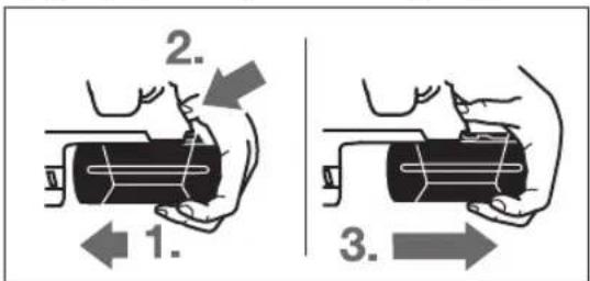
106 BnHrtn akymnytophy 6aTaapeio 11:
- PnTnCHiB aKMyIaTOpy 6aTapeIO do HIXKN eNekTpOpiPnIaNy (1.) iOHOuacHO HaTnCHiB Ha KHOIky po3bNOyBaHHA 18 (2.).
BntarHtB akymyTApHy 6aTapeo3 eNeKtpOnpnaNy HactinbKn, u06 3'ABnAoc yepBOHa cmyKa (3.).
- Ue pa3 haTNCiHb Ha KONky po36nokyBaHHr 18 i NOBHCTIO BHTIHTb aKymyIATOp.
IIndKaTop 3apJxKeHocTi akymyTApToHo6Taapei
Tpnehi cbiitnoiOn iHnikatopata 3apJxekHeOCTa kMyIaTOpHOi 6aapeei 20 noka3yIOb CTynIHb 3apJxekHeOCTa kMyIaTOpA 11.3mpkyBaHbTexHIKN 6e3NeKN OnHTyBaTH CTAH 3apJxekHeOCTa kMyIaTOpA MOXHa IINHe Pn 3yHHHeHOMyeNEKTPoPpHnadi.
HaTnCHiB Ha KhoNky 21, uo6 nepeBipn CTynih3apJdxKeHocTI (MOKNBO TaKoK KOIN akymyIaTOP BnHHTNI).Pn6bl.uepe35cekyndinikatop3apJdxKeHocTIakymyIaTOPHObatapeirache camOCTiHo.
| Свittлodeи | СмнICTь |
| Свічени 3-x зelenени | ≥2/3 |
| Свічени 2-x зelenени | ≥1/3 |
| Свічени 1-ro зelenноу <1/3 | |
| Міганney 1-ro зelenноу pezeрь |
Kkuo nicna HataNcKaHHa KhoNky 21 Hi oDnH CbitnoioJ He 3aTropaeBcAkyMnyTop BmWOB 3 nay i noR Tpe6a NOMIHATN.
Iiuc3apJkaHHWBnKO3aTOpHOTbC0INH3aOHNMI notIM rachyTptn3enehiCBITNOIOJN.AkymyIaTOpHa 6batape NOBHCIO3apJxHeA,AKo6e3nepePBO CBITATBCr Tpn3enehi CBITNOIOJN.Pn6bn.uepe5XBnIHnicraToro, AakymyIaTOpHa 6batape 6yDe nobHcTIO 3apJxHeA,TPN 3enehiCBITNOIOINHOBYrachytb.
DdaTkoBa pyKoTka
KopHcyItecN pHnAOM nHwe 3doaTkoBOIO pyKoRKOIO 16.
NobepaHHHdoataKOBOpy KoRTKn (nB.MaB.B)
IodatKOby pyKoTky 16 MoKHa NOBepTaTH B 6yNb-Ke neOxHn, IIO 3aBe3neUe 3pyuHy poBtgy 6e3 BTOMHeHHpyk.
- POBepHitb pykydoaTkoBOI pyKOATK16 npoTHCTpIKN roHHnKa i BCTaHObitb doaTkoBY pyKOATy 16B Heo6xIDne noLoKeHHa. Picna boro3HOby Tyro 3aTARHITb pykydoaTkoBIpyKOATK16 NOBepTaHHaMa CTpIKOHO roHHnKa.
CniDkyIte 3a THM, uO6 3aTHCKHn NOcOK IOaTKOBoi pykoAHTK 3hAxoHbCBA BpepeBaehomy dna Ibo r naHa Kopnyci.
Bn6ip cBepdnnbHoro natpOHa i po6oynx ihcTpymEnTiB
IJIpepopauii iIOB6aHHa Bam notpi6hi po6oHi IHCPTyMeHTN 3 SDS-plus,AKI MOKHa BCTPOMHTN CBepnInbHn natpoH 3 SDS-plus.
ДлгСВЕРДЕНH6e3уdapyВДЕРБИHи,МETani,КЕРAMi i nlaTMaci,aTAKOx3akpyuBaHnYTBHNTIB BHKOPNCTOBYHTbCpo6ouiIHCTpymEnTH6eSDS-plus (Hanp.,CBepda3UINIHDPuHNMXBOCTOBKOM).ДлгТaKHX po6ouhIXHcTpymEnTIBNOTpiHmWbDko3aTuCKHn

YkpaHcbka|161
CBePnHbHn natoH a6o 3y6uactn CBePnHbHn natoH.
BcTaHOBHeHHa3HimaHHa 3y6actoro CBepnIbHoro natoHa (GBH 36 VF-LI Plus)
I0paOBOATn 3poOUMInHCTpyMeHTAMn 6e3 SDS-plus (HaNP., i3 CBePnOM 3 uINIHpNHyHM XBOCTOBKOM), Tpe6a MOHTyBaTH nPnDAthm CBePnINbHn NaTPOH (3y6aactn a6o WBNkO3aTHckHN CBePnINbHn NaTPOH, npnnaJ).
MOnTAX3y6yactoro cBepdnnbHoro natpoHa (nB.man.C)
3akpytib xBOCTOBK 3 SDS-plus 24 B 3y6actn CBepdINbHn NaTPOH 23.3aΦikCyTe 3y6actn CBepdINbHn NaTPOH 23 3a DOnOMoTOOΦikCyUOTo rBHTa 22.3BaXaIte Ha Te, IOΦikCyUOHN TBHNT MaE nIby pI3b.
BcTpOMnHH3y6actoro CbePnHbHoro natoha (mB.MaI.C)
IpoHCTiB KINHKXBOCTOBHkA ITOHX3MaCTiB Horo.
IIOBepTaOChN, BCTPOMiTb 3y6uactn CBepeHnbln Hn NaTPOH XBOCTOBHKOM B3aTHCKaU, Uo6 Bin yBiINoB y 3auenneHH.
- Ipepeipte fikcaio, notarhybun 3a 3y6actn CBepnnbnn natpoH.
BnMaHHa 3y6uactoRo cBepdnnbHoro natoPOna
NotarHtBphiKcyuoy Btykny 5 Ha3ad i 3HIMitb 3y6aactn CBepdNbHn NaTPOH 23.
BnMaHHBCTpOMHaHH3MInHOrcBepnnbHoro natpoHa (GBH 36 VF-LI Plus)
3MiHHn CBepnIbHn NaTPOH SDS-Plus 2 MoKHnJIerKo 3aMHHTn HaDQHaHn WBNKO3aTHCKHN 3MiHHN CBepnIbHn NaTPOH 1.
BnMaHn3minHOro cBepnnbHoro natpona (nB.man.D)
NotarHbHa3ad fikcyue kInbue 3minHoro CBepnHbHO ratoha6, npntpmaTe HOro B bOmy NooxeHHI, notarHyBwn Bnepei, 3HIMtB 3mHnn CBepnHbHN natoh SDS-plus 2 abo WbNko3aTnCKHN CBepnHbHN natoh 1.
3axnauTe BHTaHHTn 3MiHHN CBepeHnBnNaTPOH BID 3a6pydHeHb.
BcTpOMnHHH3MINHO CBepeINHBHO rnatPOHa (nB.MaI.E)
BHKOPNCTOByTe NHe OPHHnHaJIbHe O6IaHaHnI 3BeptaTe Pn ybomy yBaIy Ha KInbKicTb po3ni3HaBaNbHnx 6Op03eHOK 26. Do3BOJnE7cBnBOPNCTOByTHnHe 3mHHi CBePnHbHi NaTPOHn 3DbOMa 6o6InbSe 6Op03eHkAMn. Pn BHKOPNCTAHHI 3 cIM ENEKTPOpnpnaDM HnpiDAtHOrO 3mIHHO r CBePnHbHO rNaTPOHa p6oOH nHCTpyMeHT MoKe Ni d Yac Po6OTn BNCOHTn.
- Ipeed BCTPOMHNNM npouHnAte 3MiHHN CBepnIbHn NpTPOH i 3nerKa 3MaUyTe BCTPOMIOBAHN KIHYNK.
-06XbaTb 3MIHHN CBepHINbHn NaTPOH SDS-plus 2/WBIDKO3aTHCKHN 3MIHH CBePdHbHn NaTPOH 1 BcIEO DIOHOHeIO. BCTpOMtB 3MIHH CBePdHbHn NaTPOH B H3D0 25, OJHOuacHO NOBepTaUOHyo, IO6 NoyIocB iDuyThe KlaaHaH.
-3MIHHN CBePdINbHn NaTPOH CTOnOpHTbCn aBToMaTHNo. NotarHyBn 3a3mHHN CBePdINbHn NaTPOH, NepeBipTe HOro fikcaio.
3amihapo60yoro iHctpymenta
Pnno3axnHKnOBNaqOK 43ano6irae notpannHNO B nataponnny biCbepeHHN iicac po6oTn. iid cac BCTpOMnHnPo6Ouro IHcTpymEnTa cnIdkyte 3a TMM,IO6 HE NOKoHTn Pnno3axnHKnOBNaqOK 4.
YpaizonKoJKeHHaHnno3axHcHOro KOBnaqka HOro Tpe6a HeraiHo 3amInHT. PekomeHcyTbcra po6ntu Ce B cepbichm MaIcTePHi.
3amHa po6o0oro iHCTpyMeHTa (SDS-plus)
Bctpomnnnno po60nx inctpymentrib 3 SDS-plus (nB.man.F)
3aBnKn CBePnHbHomy NaTPOHy 3 SDS-plus po6oyn IHCTpymeHT MoXHa npOCTo i3pyHo MInrN 6e3 BHKOpNCtAHH JDoAtKOBHX IHCTpymeHTIB.
- GBH 36 VF-LI Plus: BCTPOMITb 3MIHHN CBePdINHBn natpoh SDS-plus 2.
-ПрочпстбКИнчк рбочого ИСТурмЕТа,ЯкIMВIBBCTPOMNЯсьCBnATPOH,I TPOXNHMaCTITbHOrO.
IIOBepTaOuN, BCTpOMiTb po6OuH iHcTpymeHT B nAtpoH, 06B1h yBiHouB y3aenneHn.
-NotarhyBun 3a pObouH INCTpyMeHT,pepeBipTe NOro
Poboun IHcTpyment i3 SDS-plus cKOHCTpyOBaHn TAK,IO6 BIn mir BinbHo pyxatncB. Bpeyntati npo pOboti Ha xOnocTomy xodi BNHKaepadiaJIbHe 6nTTI. He He BnNBAe Ha ToCHt bnpocBepdneHOrO OTbOpY, OckINbKn npn CbpDneHHI CBepNo caMoUeHTpyETbcR.
BnMaHnpo6OuX IHcTpymeHTIB 3 SDS-plus (nB.MaI.G)
NotarHITb pikcyuoy Btynky 5 hazad i BnTARHITb po6ouh IHCTpymENT.
3aima h po604oro inctpymenta (6e3 SDS-plus) (GBH 36 VF-LI Plus)
BcTpOMnHnHpo6OoRo iHcTpymeHa (mB. mAn. H)
BkaibKa:He BnKOpncTObyTe pOoui nHcTpymEnTo 6e3 SDSplus neppopaui iIOb6aHH!Poboi nHcTpymEnTo 6e3SDS-plus iXCBepdInhNbHn NaPOH NOWKOJxIbCn npneppopaui iIOb6aHHi.
BCTPOMiTb 3y6uactn CBepdHnHbHH NaTPoH 23 (INB. BcTaHOBHeHH/3HimaHHa3y6uactoro CBepdHnHbHorO naTPoHa, ctop.161).
- NObepTaOuH, BiKpnHe 3y6bAcTn CBepeHnBHN naTPOH 23, uoB HBoRo MOxHa 6yNo BCTpOMtN pObouH IHCTpymEt. BCTpOMtB poOouH IHCTpymEt.


162|YkpaHcbKa
BCTPOMITb KIOU DO CEBEPINHBOHO NaTPOHa Y BiNOBiHi OTBOPH B 3y6aCTOMy CEBEPINHbHOMY NaTPOHI 23 i pIBHOMIPHO 3aTARHTb po6OuH INCTpyMeH.
IIOBepHITb nepemHKaup pexmMy yapib/OeptanHH 13 B NOJNOxEHn《CBepDneHHA
BnMaHH po6oOro IHcTpymeHa (INB. Man. I)
-3aDOnOMOIOKIIOuaDOCBEPINbHOroNaIPOHa NOBepHbBTyIKy3y6aCToROCBEPINbHOroNaIPOHa23 IpOTNCTPIINrTODNHHNkA,IO6MOJHa6yNoBNHHTn POboOHInCTpyMeH.
3aima p0600r0 iHctpymenta (6e3 SDS-plus) (GBH 36 VF-LIPlus)
BcTpOMnHn po6oOto IHcTpMeHTa (DUB. Man. J)
BkaibKa:He BnKOpncTObyTe pOboi IHcTpymEnTH 6e3 SDSplus neppopaui iDob6aHH!Poboi iHcTpymEnTH 6e3SDS-plus iix CBeplNbHnn NaPOH NnKOdKyIObca npineppopaui iDob6aHHi.
BCTPOMITbWBNDKo3aTNCKNH3MIHHN CBepdINHBHn NaTPOH1.
IIO6pe TpHMaTe fikcyuOe KInbue WbNdko3aTHCKHO 3MIHHOR CBePnINbHOro NaTPOHa 29. NObepTaHHAM nepeDhBoI BtynK 28 BiKpnIte 3aTNCaay po6oHOr IHCTpyMeHTA HAcTlBKn, Uo6 MoKHa 6yNo BCTPOMTN p6ooun IHCTpyMeT. IPrTpHMaTe fikcyuOe KInbue 29 i 3 CNIO NOBepTaTe nepeDnHO BtynKy 28 B HAnpMky, NOKa3aHOMy CTpiKIO, NOKn He NouyETbcBdUyTHE KNaauHHa.
IOTARHyBUN3a pO6oHnIHCTpyMeH,nepebiTeMiuHITb nocadKn.
BkaibKa:Kkpo natpon BiikpnTno do npny, npn 3akpyuBaHHi natpOHa MoKe yTuNCaHnI natpon He 6yde 3akpNaBATncr.
B Takomy BnnaKy nobepHItb nepeHIO Btyn Ky 28 Odn pa3 npToH HaprMky, noka3aHOrO cTpiKoHO. Picra zbo ratoH moXHa 6yde 3akpTH.
- NObepHITb nepeMnka pexmmy yapib/OeptaHHA 13B NOIOXeHHA CBepeHHA.
BcTpOMnHnHa akymyIaTOPHO6aTapei
BcTaHOBIb nepeMnKaHnpaMky o6ePaHH8 BcepeHneNoJoxEHn, 063aNo6irn HeHaBMnCHOMy BMnKaHHIO eNekTPOnpnAyn.
BCTPOMITb 3apJxKeHn akymyIaTOp 11 33aNy B hixky eEnKtpoIHCTpyMeHTy. PInTHcHITb akymyIaTOpHy 6aTaapeIO, uO6 BOHa NOBHcTIO 3aIIuA y Hixky, To6To uO6 ueBOHOy CMyKkHe 6yNo BnHO i 06aKymyIaTOpHa 6aTapeIdo6pe 3aΦiKcyBaIacr.
BctahOBHeHHpeKmmypo60TH
3a donomoro npemnka pexmy ynapi/boeptaHH 13 B6epitb pekm po60tn eneKtpponnay.
BkaibKa:MiHrtepeKIMpo60nIINHeHaBMKHytomy eNeKTponpnni!BInwOmypa3ieneKTponpnnlAdMoKe NOWKODNTNC.
- 3miHHT peKHM pO60TH, HATNCHTb KHONky po3bKOyBaHHa 12 i NOBepHt b nepeMnKaU peKmMy CBepdienHH/IOB6aHHa 13 B6aKaHe NIOJKeHHa, IO6 BIn BIDuyTHo 3aIwOBy 3aueNHe.
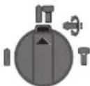
PonokenHnI npopauB 6eOHi a60 KaMeHi
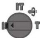
IonoKeHHnIcBepDneHH63yapaby DepeBHHi, Metani, Kepami i nnaTmaci, a TAKOXII 3aKpyuBaHHr TBHITIB

YkpaHcbKa | 163
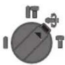
PonoxeHHVario-Lock peryuobHHn nooxeHHpo6ofoIhctpymehTa npn do6bHH
Bcbomy nonoXeHHi nepemkaay pexmy CBepdneHHa/0D6bAHH 13 He pfikcyTbca.
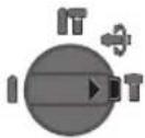
PonokehnnaDIOB6aHH
BctahOBHeHHHaHnprMky 6eptaHH
3a donomoro npemHKauHa npamky opeTaHH8 MoKHa MInrHn Hapmok opeTaHHIhCTpyMeHTa. Ondak ue He MOxNIBO, RkUo HaTHCHyTN BmNKaY 10.
06eptan npabopy: nepecyhte nepemnkaHnpanky o6epaHH 8 do ynpoy B noJoxehn
06eTahnH hibopy: nepecyHbTe npeemnka Hapamky o6eTahnH 8 do ynpoy B noIooKeHH
IJIpefoauiB6eToHcBepnEnHHIOB6aHH3aBXIN BCTAHOBIOHTe npabHnpanmOKOeptanH.
BMnKaHHBmKnKaHH
3MipkyBaHb 3aoaJdxHe eneKtpoeHeprB BMkai Te eneKtpoiHcTpymENTnne Toi, KOni Bn 36paTecb KopHcyBaTHCA HMM.
-106 yBIMKHyTH eneKTponpnpna,HaTNCiHb Ha BIMnKa
Pn npwmy BMkahHi eekTpnpnady MoKe CTATNC 3aTpMka 3anycky,CKInbKn enektpoHika npnady Cnoaatky Mae cKOHphiIpyBaTHC.
- Uo6 BmKHyTH eneKtpponpnaad, BiDnyCTtB BMnKau 10.
Hactpoobannkibkocti 6eptiB/kinkbocti yapab
KInbKicTb 6opeTb YbIMKHyTORo eNeKTponpHnady MoXHa nIaBHO peryIIOBaTH 6IbHM Nc MeHWM HaTHCKaHHM Ha BmNKaU 10.
PnHecInbHOMy HATNCKyBaHHi Ha BmNKauch 10 KINbKICTb o6eptIB/KINbKICTb yadip IB HeBENka. Pn36inbWeHHi Cnnn HAHTCKYBAHHI KINbKICTb o6eptIB/KINbKICTb yadip 3pocTaC.
Electronic Precision Control (EPC) (Диь. М. L)
ФункьяЕСКОРнCSHа npi po6oTAX 3 ydapAMN BчуTNBnx MATEPIJANX 3aBДANKI NOBIbHOMy po3rOHy i 3MeHSeHIN po6ouK KInbKocTi o6eptIB.
IocyhTe npemKau EPC 30B6kaHa neoKeHHa.

IIOJKeHHaMakCMMaJIbHOIpo6Ooi KJIbKoCTi o6eptIB

Ponoxhenn nno nobinbHoro po3rohy i 3mehenoipo6ooyi KInkbocti oebptib
3ano6ixna myfta
Pn3aknnHeHHa6o cinaHnI eektpponnay npBbOcBepnHbHorO uHHdEe BmHKaetcbc.3BaKaounHa CnH, 0o BHNKauTb npu cBOMy, 3aBXn Do6peTpMaTe eektpponpaDbOMa pykamn i 36epiraTe ctKe nonoKeHH.
y pasi 3actpbaHnB BHMKhitb enektpponpnai 3binhltb po6oHm IHCTpyMeT. PnB MHKaHi eektpponpnaIy i3actprrnM po6oHm IHCTpyMeHToB BHHKaIOb BENKi peakuiHIMOMeHTN.
AbapiiHe BmKHeHHa (Kickback Control)
ФункuarшвдкогВIMKHeHH(Kickback Control)
3a6e3neuye KpaunKoHTpoB HAD eNkTPOiHCTpyMeHToM.
IpiHecnoiBaHOmy IHepe6auyBaHOmy 0eptaHHI eneKtpoiHCTpymetaHaBkpyrO cci CBepda eneKtpoiHCTpymENT BHMKaetbcr.
- Dnra NOBTOPHORO yBMKHeHH BIDnyctITb BmHKaI3HOBy HATNCHTb NOrO.
Ipo WbNke BmHKaHH CbiuHb 6nMaHH iCbitKn 14Ha eneKTpoiHCTpymehTI.
UWBnke BmHKaHn cnpaobByc nWe ToDi, KOHN eNKTPOiHCTpyMeHT npaioe 3 MaKCHMaIbHM qHcIOM o6epTIBMOKe BInbHO o6epTaHc HABKOIO OCI CBepDna.
IINKATOP KOHTPOHIO 3a TEMNepaTPOI
YepBOHn CbITNoIOI iINKAtopa KOHTpOIO 3a Tempepatpo19 cnHAni3ye, kAIO akyMnyTOp a6o eneKtpOnikaeneKtpPpHnady (npn BcTpOMneHi akyMnyTOpHi 6aTaapei)3hAxOJrBc43a MekAMN ONTMaNBoHO TEMpePaTHOrDiJana3OHy. B TaKOMy BnAnkMy eNeKtpPpHnAd He npaQoe a60 npaQoe He Ha NobHI nOTyXKnOCTI.
KoHTpoB 3a TempepaTPO aKymyIaTopa:
- YepBoHnCBiTIOJIO196e3nepepBHO CBITNbCpN BCTPOMJIHHI aKymyIaTOPaB 3aprAHHN pNCTPI: aKymyIaTOp 3haxoITbC3a MekAMN DOpyCTMOrO dIa 3apxKaHn diana3OHy TeMnepaTyPiB O°C Do 45°C, i Horo He MoXHa 3apxKaTH.
- YepBoHnCBiTIOJIOI 196BIMaE npnHaNTCKaHHi Ha KHONKY 21 a60 Ha BmHKaU 10 (npn BCTaHOBNEHHI akMyNtOPHI 6ataei): Tempepatya akMnyTOpHOI 6ataei 3a Mekamn DoNyctHMoro diana3oHy.
- Pn Tempepatyi akymyIaTopa noHa70° C eNEKtponpnaAD ABToMaTHUHO BmHKaTeBcRdoTHNip, NOKN TempepaTy aKymyIaTopa HE BCTAHOBITbCBA MExkax ONTMaJIbHoro dIana3OHy.
KohtpoB 3a TemnepaTpyo eJekTPOHIKeJekTponpnaNy:
- YepboHHcBtIOJIO196e3nepepBHO CbITnTbCpNnHaTHNCHEHHHbAMNKaU 10:TemnpaTypa eNEKtpoHInENEKtpoPnPnady MeHsA 3a 5^ afo 6iNbSA 375°C.
- PnI Te Mnepatyip noHAD 90°C eEnKtpoHika enKtponpnaNy BHMKaetbCn Do Tnx nip, noKn po6oataemepatypa He BCTaHOBntbCn B mexk AxOnyCTMOrO diana3ohy.


164|YkpaiHcbKa
Bka3iBKn 0oO p6oTn
BctahOBHeHH rHn6HH CBepdHeHH (mB. man. M)
3a donomoroo 6mexyBaayn6HH 17 MoKH
BCTaHOBJIIOBAHT Heo6xIDHy rHbHHy CBepeHnHA X.
HaTnCHiB Ha KhoNky DnpeRyIIOBaHHa O6MeKyaBa a I 15 i BCTpOMiB o6MeKyBa u N6Hn BdoATKOBy pykoRTky 16. PnFleHHHa o6MeKyaBai rN6HH 17 NOBHHe DnBHTNCa DOHN3y.
Bcptpomitbpoobounihctpymert3SDS-plus doynopy B natpondSDS-plus 3. IhaKepe pyxomictb po6o0ro IHCTpyMeHa3SDS-plus MOKe npH3BOHTN DO HENpaBnIbHOrO BCTaHOBNEHH rINbHN CBePdNEHH.
BnTrrHtB 6mexyBaay n6nHaCtInbKn, uO bIcTaHb MIX KINKOM CBepnai i KINKOM 6mexyBaay rnnbH BIDNOIBaNa 6axahin n6nHi CBepneneHH X.
3mihennnoIonoKeHHpi3a(Vario-Lock)
Bm moxete 3a#kcybnt pizc y 36 nooKeHHx. Lc daTb Bam 3M0r npauobatn B ONTHMaHbHomy nOIOKeHHi Tina.
BCTpOMITb pi3eub B natoH.
IIOBepHbIpeMnKauepeXmMy CbePdHeHH/IOB6aHH 13BnoOKeHHA《Vario-Lock》(INB.«BCTaHOBHeHH peXmMypo60TH,CTop.162).
IIOBepHITb3aTnCKau pObooyoro IHCTpyMeHTa BiNOBiHO do 6axaHOro noloxeHHp3u.
IIOBepHITb nepemikau pexmmy CBepnneHHaOB6aHH 13BnoOxehnA《DOb6aHHa.,NATPOHTenep 3aΦIKcoBaHH.
-ДяdoB6aHHNoTpi6Hn npaBn HaprMoK o6eTpHa.
BctpomnHHH6it(nB.man.N)
Pnctabnte enektpponna do raKu/ribHTa Hne y BmKHYtOMy CTahi. Po6oHi nCtpymEnTH, 0o o6epTaIObCR, MoKyTB 3ickOB3yBatn.
ДябВamNotpibhaYHIBePcAblHa DepeKabKa 31xBOCTOBHKOM SDS-plus (npnna).
- PpOuHCTtB KIHcHK XBOCTOBNk i TPOXH 3MaCTtB Horo.
IIOBepTaoU, BCTpOMITb yHIBePCaIbHy dePekKaBky B naTPOH, 06 BOHa yBiMa y3aenneHH. - Ipepeipte fikcaiu, noTnHyBm 3a yHBepcabHy nepxabky.
BcTpormitb 6iTy B yHibepcaIbHy dePkaBky. BnKOpncToByTe NmN 6Itn, 0o nacyIbDo rONOBKn TBnHTIB.
IIO6 BnHHTyHIBepCaBHy DEpKABky,NOTaHITb φikCyOuy BYtynky 5Ha3a i BNIMiB yHIBepCaBHy DEpKaBky 31 3 NaTPOHa.
Demnpep

IHTerpoBaanH demnep 3mehnye Bipauio.
M'ka haknaika 3meHwye He6e3neky BucnHaHH npnady 3 pyk i 3a6e3neue Kpaue yTpmaHH npnady B pyci i 6iBbwy 3pyuHic7b.
Bka3iBKn 0oO onTmAlbHoro NOBQKeHHa 3 aKymIyIaTOpOM
3axuetaeakymyIaTOpBIDBOIINBOH.
36epiraTe akymyIaTOp nHne npn TempeIpyi BiD-20°C 1050°C.3okpema,He 3aIIuauTe akymyIaTOp BnITKy BMaunHi.
YacBIDyacynpouuAteBeHTnIaHHiOTBOpnAkymyTotaMRAKHM,YNCTHMICYXNMNEH3NIKOM.
3aHaTTO KOPOTKa TpHbAInCTb po60Tu nICn 3apJxHnB CBiHTb np Te, Ioo akymyIaTOp BnuepePnaB ce6e iNoro Tpe6a NOMIHrTH.
3BaKaIeHaBka3iBkNIOO BnAaJIeHHA.
Texhihe 06cnyrobybaHH i cepbic
Texhihe 06cnyrobybAHn i ouueneHH
Ipey ycima MaHinyuaiMaN3 eNeKtpponpnaDom (Hanp.,TexHUYHM 06cnyroByBaHHM,3amHOIO po6oOro iHCTpyMeHTaToO),aTakox npn Horo TpaHCnpOpTyBaHHi 36epirAHHI BmMaTe AkyMynrTopHy 6atapeo3 eNeKtpponpnaDy.PnHHeHaBMCHOMyYBIMKHeHHI BmHKaya icHyec He6e3neKa npaHeHHA.
106 enektpponpnaia npauOBa kicho i hadiiHo, trmaite npnai i bENTnuaiHi OTBOPN B uhtoti.
YpaizonokjKeHHnHno3axHOroKOBnaUkaNoTpe6a HeraiHo 3amInTH.PekomeHdyctbca po6HTNceB cepBicHI MAnCTepHI.
KoHHn pa3 nicra 3akIHueHH po60Tu npouuauTe 3aTmckaypo6OOrIO hCTpyMeHTa 3.
Cepbic Ta HadaaHna KOHCynbTaui Ndo BHKOPnCTAHN npOdykuii
CepBicHa MaHCTepHb BIDIOBcTB Ha 3aHHTaHH CTOCOBHO pemOHTy iTexHrHOro o6cIyROByBaHH BaWoR O BnPo6y. MaHONKn B DeTaNAX i HfOpMaio 0do 3aNacTHN MoXHa 3HaHTn 3a aDpecoo:
www.bosch-pt.com
KomHaDa cnBpObiTHNKIB Bosch 3 HauHHa KOHcybTauii
Udo BnKOpNCTAHNA npOdykii i3 zaoBoneHHM BiINOBiCtB
Ha BaWi 3anHTAHNA CTOCOBHO hawoi npOdykui Ta npnnaDn
Do Hei.
PnB Cix DoaTkoBnx 3aHHTAHHx Ta 3aMOBneHHI 3aNactH, 6yNb nacka, 3a3NaueIe 10-3HaHn HmOp dJa 3aMOBneHH, IIO cToITb Ha nacnpTHI tabnui npOdykTy.
TapaHTIHe 06cnyTOBbAHnH i pemOH eEnKToPiHCTpMyTe 3diHCHIObTa BIDIOBIDHO DO BIMOR I HOPM BnroTOBIOBaHa Ta TepHToPi BCix KpaIH NHE y fipMOBx a6o ABTopN3OBAHHcePbCINHX CEHTpax fipMN (Po6eT BoW). IPONEPEDXHH! BkOpHCTaHH KOtpaKaTHOI npOyKII He6e3neue H E kcnIpyaTci I MOKe MATn HerATNBHI HacNIKn DnA ZdOpOB'. BnroTOBNeHH I pO3NOBCHOJENH KOnTHPaKaTHOI npOyKII nepeCniDyETcb 3a3aKOHOM B aDMiHicTpA TNBOMY kPmImHaNbHOMY nopAky.
Ka3akua165
YkpaHa
Bou Cepbicn LcHtp eneKtpoiHCTpymehTIB
Byn.KpaHna1
02660KbB60
Ten.: +380 44 490 2407
ΦaKc: +380445120591
E-Mail: pt-service@ua.bosch.com
www.bosch-professional.com/ua/uk
Adepca PeriohaBnHex rapaTtiHnx cepBichnx MaicTepeHb 3a3haeHa B HaiaOHaNbHomy rapaTtiHomy TaHOi.
TpaHcnpTyBaHHa
Ha doani nitiiebo-oHni Akymnyatophi 6atapei
po3noBcIOxJyOToBCB BMOTnIooTOpaHCnoptyBaHH
He6e3neuHnx BaHTaXiIB. AkymnyATopHI 6atapei MoKytb
peB03THCA KOpHCTyBaem ABOMoBihm TpaHCnoptOM
6e3 Heo6xIDHOCTI BNOKAHHN DoaTkoBNx HOPM.
Pi nepecnui TpeIMn Oo6amn (Hanp.: nobITpaHHM
tpaHcNoptom afo TpaHCnoptHM ekCneHTOpOM) Notpi6Ho
doepKByTaHcOo6NBHX BMOrIoYO npAOKBKn Ta
MapkyBaHH. B cybomy BNapKy npn NiDroTOBuI NOCHKN
NoBHHeH pRIMMaTH yactb EKeCnept 3 He6e3neuHNx
BaHTaXiB.
BicnaiTe akyMnyTOpHy 6aTapeo Nne3 HenoKoJKeHMM KOpNycOM. 3akNeIte BIKpNTi KOHTAKTN Ta 3anaKyTe akyMnyTOpHy 6aTapeo TAK,IOb BOHa He CObaIacByaKOBci.
IOTPMMyTEcA,6yNbNaCkA,TaKoX MoKNBHX DoaTKOBHX HaioHaBnHx npinnicB.
Ytniiaui

Enektpponpna,akymytnophi6atapei,npnanaia ynakobky Tpe6a3daBnHa ekonoriuHo uHcTy nobtopny nepepo6ky.

He BHKnJaTe eEnkTponpHnAdn Ta akymyIaTOpHi 6atapei/batapeienB nobyTOBe cmITII
Пишдя краин EC:
BidnoiHO do EBponecboi DnpeKTHBN 2012/19/EU ta
EBPonecboi DnpeKTHBN 2006/66/EC BiDnpaobahi enek-
TpoHCTpyMeHTN, NOKoJKeHI akymyIaTOPi
6batae/i/bataeIKN abO akymyIaTOPi 6batae/i/bataeIKN,
IO BIDnpaIOBAHN Ce6e, NOBHHI 3daBaTHCn OKpeMo i
YTNJIAYBaTHCn EKOJIOrIHu YCHTM CNOcoBOM.
AkyumnyTopn/6aTaapeKh:
NITIEBO-IOHHI:
Bybnacka,3BaKaJaTe Ha BkazIBKn Bpo3dini «TpaHcnpTyBaHHa», cToP. 165.
Moxnbi3min.
Kazakwa
HdyinH eHm yHkapactbipraH naDanaHy KkaTapbHbKpaMbHa naDanaHy XeHHeiOCbl HcaybIK,cohmeH bipre KocbMwapap da bony MyMKH. CKeKTi pactay KaNbI aKnapat KocmbWada 6ap. OHidEHPRE MMeNEKETypaBbaknapat EHMHH KopnycbHda KHe KocmbWada KepctinreH.
EHpy Mep3iH yckaynbKbTH COHfBt BtIHne Kepcetinre.
IMnptTayuifa KaTbCTb 6aHaHbC MJIIMeTI KANTaMa da
6epireh.
Ohimdi nai danany Mep3imi
ΘHIMHIN Kb3MET ety MEP3iM 7 kbln ΘHdipinreH Mep3imHe6 bactan (eHdpy KyH 3aybit TaTaaHacbHa Jaa3bnFaH)ICTeNe 5 kbln cKaTaFAHHaOH, eHIMDi TEKcepyi (cepBnCTIK TeKcepy) naDalaHy YcbHbImaHbl.
Kb3METKeHemece naDanahyubihk kateniktepi MeiTeH WbyFy ce6entephiH ti3imi
TytKacbIMeH Kopnycbl6y3bnFaH 60nca,ehimdi naHaanhaHbI3
- eHIM KOpnycbiHaH TiKeNeI TyTIn WbIKCa, naJaIaN6aHb3
TOKcMb6y3bIFAHHEMeceOKwaynaycb360Jca, naDanaH6aHb3
-kayBH-waabHKe3iHc6biptTa(daIa) naIanaHaBb3
Kopnyc iuihe cy Kipce KypbnFbHbKocybl60nMaHb3
K Θn yWKBH WbIKca, naJaIaHa6BaHb3
KaTbI Dipin KeiHne naHaHaHa6aHbI3
Uekriky6enrinepi
- TOK, CblmbHbH TO3ybl HeMece 3aKbIMdAHybl
- EHIM KOpNcBbHbH 3aKbMdaNybl
Kb3MeT Kepcety Typi MeH xiniriri
OpaandaanhydAncoHemimTa3anayycbHbnaBb.
CaKray
- K y pf a K Jxepde caKTay KepeK
KOFapbI TempepaTypa Ke3iHe HxHe KYN CayneepiH 0cepineH anbcakTayKepe - cakay kezihende TEmnepaTypaHbIH KehetaybiTKybiHaH KopfayKepeK
- opaMacbl3 caTay MymKIIh EMEc
- cakay wapTapbI typabIKocbIMua aknapaTanyuH MEMCT 15150 (WapT 1) KxKaTbIH kapaHb3
TacbImaIay
TacbImaIay KeiHne OHIMDi KynAtyFa KAne Ke3 KeNreH MExaHKnBikkknanEtyReKaTahTbimCaBHaDbl
60catoy/xykTey Ke3iHne naKeTTi KbICatbH MaUNHaapdbI naDanahyra pyKcat 6epinmeNi.
TacbMaJday wapTapbl tanantapbH MEMCT 15150 (5wapt) KyKaTbH OkbHb3.
16Kazakka
KayinciHKyckaynapbl
3neKtp KypandaBihH kannbl Kayinci3diK Hcykaynbikapbl
ECKEPTy Bapnbk Kayinci3ik HycKaynbKTapbH XaHe eckptnenepiOkbHb3. TexHN
KaIbIK Kayinci3ik HcKaynbKTapBH XHe eCKeTnepepi CaKTaMay TOKbIH COyBHa, oT XHe/Hemecae aybip KaPaKaTAtHynapFa aNbIN KeNyIMyMkIH.
BonaawKaXyMbIcTap yuH Kayinci3ik HycKaynbKTapbl Me hecKeptneneepi caKtan KoHbHb3.
Kayinciik HcykaynbkaptbHa nainanhaBnFAn "3neKtp Kypan"ataybHbH XeNiIeH Kyat anaTbH 3neKtp KypanapbHa (XeNlirK Kabeni MeHen) XaHe aKkyMnyTOpDcH Kyat anaTbH 3neKtp KypanapbHa (XeNlirK Kabeni Koc) KaTbc6ap.
XymbicopbHbHkayinci3di
KymbocpHbInTa3aXeHaKaCbIxapblkTaNFaH XaFdaNyaYcTaHb3.Taptin Hemece Xapbl6oImarAH Kymbc aMakTapblXa3aTaBIM OKHaIapFa aBn Kenyi I MYMKIH.
KaHaTbHcyHbIKtBtKTap,ra3napHeMecewaHxkbINFaH XapbIbc Kayini 6ap Kopwaya3neKtp Kypanbl naDanaH6aHb.3NeKTP KypanIapably WkBih WbIFapbIn, WaH HeMece 6ynapdbXaHdbpybMyMKH.
3NeKtp KypanapbH naDanahy Ke3iHe 6anapan Xehe 6aKa aamapbY3aKKepe weTetIi3. Aytky Ke3iHe Kypan 6aBnaybH KofantYbHb3 MymkiH.
3nekt Kayinciadi
3NeKtp Kypan wTenceninH aiBpbl po3eTkaFa cbHobi KaKet. Aibpbl eWKaHdai Θ3reTpY MmKIn Emec. Kepre Kocynbl 3NeKtp KypanapMehen eWKaHdaa anTepnik Aibpbl naDanaHaHbI. Θ3reptimere H aiBip JxHe kapaMbl po3eTkapanbpbl naDanaHy 3NeKtp TOK COFy KayinH TeMeHTeTeJI.
Ky6bip, XblnbTbH Xa6bIK, NnHTaXHe cyblkbiw CnKbI Xepre Kocynbl Kypanap cbiptbHa TmHei3. ErepeneHiz Kepre Kocynbl 60nca, 3neKtp ToBihh Cofy Kayni aptabl.
3NeKtp Kypanapbih bInFaHnah, cbi3aH caKaTbH3. 3NeKtp KypanbHbIH iHHe cy Kipce, on 3NeKtp TofbHbH CORY Kayin HApTTbIpaBbl.
3Nekp Kypanbl anbln kpy, acbl KOIO hemece aiblpbH po3eTkadaan bIbFapy ywiH Ka6enbli naDanaHbI3. Ka6enbli bIcTBtAH, maJdAn, eTKip weTtepeH Hemece KypanblH XbIINXbIMa 6OneKTEpHeH anbc XepDe YCTaHbI3. 3aKbIMdaIfAH Hemece WneeneHicKeH Ka6enbl3neKTp TOFBHbIH cOFy KayinapTTbpaBbl.
3NeKtp KypaBImeauBik Kepde Kymbic icTeceHi3, TEK cbiptTn naDanaHyf aphanFaH y3apTKbIHTbI naDanaHbIbI3. CbPTTa naDanaHyf aphanFaH y3apTKbIHTbI naDanaHy 3neKTP TOfBIHc,coFy KayniH TEmeHdTeJI.
3NeKtp KypanbH bInFaNdbKopwayda naa danany KaKeT 6oNca,ABOTMaTbI caKaTaHdbIPbIaXbipAaKbIbHnnaDanaHbIbI. ABOTMaTbI
CaKaTaNDbipFbIaXbIpaTKblTbI NaDaIaHy TOKcoFy KayniH TEmHeTei.
Aamap Kayinci3diri
CaK60bn,HeicTeNxaTKaHbHb3FaaypbkwaKeHin 60nIn,3NeKtp KypanbH petimEn naDanaHb13. 8apwaaHan KaFdaHa Hemece enitkiwi,Ankoronb Hemece dpi Ocepia actbHa 3NeKtp Kypanbl nainanaHyda cekyHtBkabAscbIbIKKaTbXapaKaTTaHynapFa anbl Kenyi MYMKIN.
XKeKaTaNtBnKIMiXHeepaBbIM KopFaHbIe K3inipikTi KNIH3.3neKtp Kpant typihe HEmecne naDanahyBaHa 6aNaHbCTbI WaHTbI,cbIPydaH CaKaTaBtBn6TeHKe,caKaTaNtBnWJem HEmecne KyNAc KaTaFbIbCb CnAaKbTI XKeKopFaHbc Xa6DbkTapbIH KIO XapaKaTAtAHy KayniH TemeHdeteni.
BaiKaycbi3 nainanahayaayak 60nbHb3.3neKtp KypabIn ToKKaXHe/Hemece aKKyMnTOpFa Kocya, OHKeTePreHcHE Hemece anbIn KpyreHcE, eWipyni Bonyiba Ke3 XeTki3H3.3neKtp KypabIn Ketepin TypFaHda, 6apMaKtBi axkbipaTkbiHTa yCTay Hemece KypblfBiHbI KOCyNb Kynde TOKKa Kocy, Ka3aTaHbIM OKHaFAnbIn Kenyi MyMKH.
3NeKtp KypanbH KocyaH anbH peTteRTH acnantapbl XHe raHa Ka KITTEpiH anbCTaBtB13. AHaNaTbH 6eIWeKTe TpyFaH acnH HeMeEe KIN JkapakatTaHnyapFa anbN KenyIMyMKIH.
KanbcI3 DeHe KyHnHe TpyMaHb3. TipeK KyHe TybpIn,epKaHaAnE3iH3iCeHIMyCTaHb3.OcbNa ci3 KytnerEH KaFdaJa 3JKeKtp KypalDb JkAckbpaK 6akblnaCb3.
KMybicka KapaMdbkHm KnHi3.KHeHemece cHnI KNIM KHMehi3. WauhHi3db,KnIM XeHKeNOrFaTbI Ko3FaMnAb6oNeWekTepeH anbc yCTbH3.KeHKnIM, OwekeHemece y3bH WauW Ko3FaMnAb6oNeWekTepre THIOI MymKiH.
1HaHcOpFbiWx3eHaHTyKbIiXa6DbikTapdbi KypFaHda, onApDbIH KocBnFaHbIFbHa X3eHdpybIC naDanbHybHa K3eKtki3iH3. HaHcOpFbiTu naDanahy waece6iHeh 6oNaTbH kayinTepi a3aTabI.
HA3AP AYDApBIHbI3!3heprnmeH Xa6dbkTaydbIH TOBkTaH He XeKeene ToK TaBnyb Hemece 3heprnmeH Xa6dbkTaydbi 6acKapy Ti36erHi aKaynaHybI caJaPbHaH 3neKtp KypaBbHbIH JxMbICbHda Kiipic naJa 6oNFaH XaFdaJa, 6yFaTTaMaFaHbHbHa K03XeTKi3in (6oNFaH XaDaJa) 6apBn, axbipatKbHtBbIK. (Θwipy) KaNbHa KaNTipiH. XeNlIk aawHbI po3eTKaDah WbIFapBiH3 Hemece anBIn - cAlMaBl akymyTAOpDbI axbipaTBbI3. Ocbapeket apkbnl b6akbnAbaTbH kaTa icke KocblNybl anDbH anacB3.
3neKtp KpapanapbH nainanahHy XHe Kty
KypanbI aca KEN KYKTeMeHi3. KyMbIcbIbI3 yWIn Jkapambl3neKtp Kypanbln naDanaHbIbI3. KapaMbl3neKtp KypalBIme KepeKTi KyMbIC aMafBIHa dpybc api ceHIMdi Kymblc icTeic3.
Ka3aKa7a167
Axbipatkbibdypbicemec3neKtp Kypanbih naanana6aht. Kocyfa Hemece eupyre 6onMaHtBn 3neKtp Kypabbl Kayinti 6bn, onbKeHdey KaKet 6oana.
Ka6bikTapbipetey,6nwekeptin anmaCTbipy Hemece KypanBiaIbn KOIOAnH aNDbH aBipbpo3eKaadH bIfapbHb3 XHe/Hemece AKKyMnTOpBiaIbn TactaHb3. Byn caTbIK epeketi 3NEKTP KypanBHaB6aKaycbI3 KocblvBuHa KOn 6epMeNi
PnAanahBImaTbH 3neKtp Kypanap6anap KOnI XeTneTIH XaHa FKaObIHbI3. OcbInapbl 6inMeTH Hemece Ocbl eckptnenepei OKMaFAH aamapra 6yn Kypanbl naidanaHyfa kon 6epmeH3. TaKipieci3 aamap kOnbHa 3neKtp Kypanapbl kayinti 6oanaBl.
3NeKtp Kypanapbkbntbkytih3. K03rMaIb1 6NeWkTepeHKeeprici3 icteyine XeHe KeTtenin KaMbayHa, 6NeWkTepeHakaycb3 Hemece 3aKbIMdAmFaH GonybHa, 3NeKtp KypanbHbH 3aKbIMdAmFaHbHa K93 KeTKi3H3. 3aKbIMdAnFah 6NeWkTepi6ap KypanDbnaDalaHydaH anDbH XeHdeH3. 3NeKtp KypanapbHbH, yPbC KytinMeyi Xa3ataBm OKrFaIapfa ce6n 6Obn kataDbI.
Keckiw acnantapdbI etkip kHe Ta3a Kynde caKaTaNbI. DpybckytinreH kHe Keckiw kneKtepi etkip Keckiw acnantap a3 Kentenin, Kecinetih6etkeohai 6abITTanaDbI.
3NeKtp KypanbH, Xa6DbIckTapdb, anMaIbI-camMaIbI acnTapdbXane T.6.0cbHyckaynapra cai NaJaIaNbHbI3. CoBbIMeH Kymbic WapTTapbImeH opBHaIbTbH apKeETepre Ha3ap aydpbHbI3. 3NeKtp KypandApBH apHaImaFaH KymblCTapda naJaIaNahy kayinti.
Akkymyntopdb naaandahy kHe KyTu
AkkymyIaTOpbik 6aTapeHbI TeK eHdpYwi KpcetKe3apdItay KypbnfbcBIme3apdTaHbI3. 3apdTay KypbnfbcIb6enrIi 6ip aKKymyIaTOpnap TyPiHe apHaIraH, OHb 6acka AkkymyIaTOpnapbl 3apdItay yuHn naDanaHy oP kayin Tdybpadbl.
3NeKtp KypanDapbHa aphanFaAkkymyTOpnpdbI fHa naDanaHbHbI3. BacaakmyTOpnpdbI naDanaHy kapaKaTapra HeMece optke Akenyi MmKIn.
PnAanahbnmaTbHnAKyMnyTOpnbTyicnenepei TybIKaybIMyMKINKbICTbIPbIHTapDaH,THbIHdapHa, KInTepDeH,WerenepeH,BHHTepeHxHe6aKa yCaK Temip 3aTTapDn CaKaTbI3.AKKyMnyTOp TYicnenepiHHapacBnDaFbKcKa TybIKany KyIKTePre Hemece optke Keenyi MymKiH.
Dypbc naaanaan6afaHbIKTaH,akkMynTOpdAn cybIKtbIkybIMKIn.OfAH Tmehi3.Ke3deCOK TReHe,conXepiCyMeHwaibHbI3.CyblkTK Ke3re THce,MeHNHaBik KEMeA1bHbI3.
AkkymyIaPdAbCyIbIKbIKTepiHITiIPKeHdpYi HemeC KIpyIMMKIH.
Kb13Met
3NeKtp KypalbHb3dIb TeK 6nIKTI mAmHaFa XaHe apHaynb6enweKtepeMeH KeHdetIHc. Con apKbInbl 3NeKtp KypalbHbH Kayinci3dirih caTaNb3.
BanranapbnaaanahyxehinderiKayinciaHcyayblkaptbl
KynakcaTafbIbHKnIH3.LybnacepiHecety KaBineiH3aKbIMdAHyblMymkH.
3NeKtp KypanbIme 6ipre KeTeKizinetih KocBIMwa TyTKanapdbI yCTaHbI. BaKbInayDbI XofAnTy 3akBIMapra anbIN KenyIMMKIH.
AnmaIbI-cnMaIbI acnTbIH XacblpbiH TOK cbIMbHa THoi bIKTHmAN XyMbICTapblOpbIHdaya Kypanbl OkaynaHbIPbIFaH TyTkAcbIHah YcTaHb3. ToK eTeIH cbMbHa THIO MetaIIbI Kypan 6eWekTePiH TOK 6epin TOK COYbHa anbl IN Kenyi MYMKIN.
Kaxetti 3eey Kypanapabih naDanaHbn Xacbipihfah KOPEK cbIMapbIH Ta6bH3 Hemece XepriikTI KOPEYbIMApbIH WkBpHb3.3neKtp cbIMapbHa TIO ePT Hemece TOK COByhA anbl Kenyi MymKiH. Fa3 Ky6bpHn 3aKbIMday JkapblcKa anbl Kenyi MyMknH.Cy Ky6bpHn 3aKbIMday MaTePnAnDbK 3NHA FFA anbl Kenyi MymKiH.
3NeKtp Kypanblnai naidanahya oHbEki KOJImeh 6epik yctan,TypaKtbl KaIbITa TpybHb3.3NeKtp Kypanbl EKI KOJImeh ceHIMdi 6ackapblnabl.
DaihHaMaHb6ekiTih3.KbIcy KypaIbHaHEMece KbiKbIkaOpHaTbIIFAH daBHaDamaKoJIbHb36eH caJIbCTbIPfAHa,6epik yctanabl.
3NeKtp KypanbH Xepre KOoHa anBbH OHbH TOKtaybH KyTih3.AmAbI-calMaJI acn an iniHin 3NeKtp Kypan6aKnaybHbH KofantyBaHa anbIn Kenyi MymKH.
AkkymyTopb1 aunahbi. KblcKa Tynbiktany Kayni 6ap.

Mbicanb,akkymnTOpdbjXbinydah,cohdai-ak y3diKci3 Kyh XkapbfihAH,OTAH,cydah Xhe bInFaand KOpFaHbI3. KApbykayni 6ap.
Akkymyntopdah 3akbimdaHefan Hemece dypbc nainanaH6aHan XkaFda 6y bhyb MyMKIN. Byn KaFdaia iKe Ta3a aya Kipri3ihi3 Xehe waFBIMap 6oIca, MeuHaBik KEmek anbHb3. Bynap TBHbC any KonnapbH titipkehdpiy MyMKIN.
AkkymyIaTOpIbTeK Bosch 3eNkTp KypanbImen naIaIaNbHbIb3. Con apKbIbIaKKMyIaTOpIb Kayinti apTbIK JxKTEyEn caKaTcB13.
IWeHeme6bpybIChKtblWtbl3aTTap Hemece cbiptkblacepapkbblnakkymynylantop3akblmdahybl MYMKIH.5ynkbicKaTbIKTanyfAanBInkenin, aKKMyJrTOpKaHybl,TyTH WbIFapbybl,KapblNyblHemece Kbl3bnKetyiMYMKIH.
ΘHIM XəHe Kbl3MeT ChnTaMaCbI

BapnbKayinc3ik HcckaynbkTapbH
KHe eckeptnenepi okbHb3. TexnKaNbIK
Kayinc3ik HcyckaynbkTapbH KHe
eckepTnepepi cakTaMay TOKbIHcofYbHa,opt
KHe/Hemecae aybp KapaKaTTahynapfa
anapbyMymkh.
3nEeKtp KpaanbHbHcypet6ap 6etti aunnnaHny HcyckaynbHbH OKy Ke3iHe OHbl aubk YCTaHb3.
168|Ka3aKa7a
TaFaiBihany60bHwaKoJdany
3NeKtp Kpyanb npfopopatopmeh 6etohb, kipniu, taTbIOFA XHe Ka coFy KymbcTapbHa apHaFa. On XHe aFaU, Metan, KepamNka, nactMaCCaHb KaFycB3 OFOA apHaFaH.3NeKtpoB 6ackaybXHe OHFa/CONFa aHanyb6ap 3NeKtp KpyandaPb da 6ypfbnya cai.
BeHHeneHren Kypamdbi 6nweKTeP
KepcetirreH Kypamdaactap HmipneHreH cypeTepi bap 6etteri 3eKtp KypaBbHbCnattMaCbHa ca.
1 Te3 KbicbinaTbH aybictbipMaBb6yPbI nTpoHbI (GBH 36 VF-LI Plus)
2 SDS-plus-aybictbipManb6yPbI nATPOhB1 (GBH 36 VF-LI Plus)
3 Kypandb6ekity opnb SDS-plus
4LJaanHacakTaTbIH6yKtbpMa
5 Békity Ténlkeci
6 Aybctbpmnbl 6yfbn natoho b6kity weh6epi (GBH 36 VF-LI Plus)
7 Dipinéydi TemeHendeT
8AHHaIy6aFbITbHbIH aybICTbIPIN-KOCKblwbl
9Tytka(6eriokaynahdpbbnfah)
10 Kockbliw/ewipriwi
11AkkymyTrop
12 KaYdybl/aHAnydybI TOKtATy KCKblBHBH6Ocary TYMeueci
13 KaYdybl/aHanybl TOKtaTy Kockblblbl
14 Kymblc XapblTbIbI
15 Tepenjikti wektey tiperih opnaty nepheci
16 KocbIMua Tytka (Beti OkuaynaHbIpbnFaH)
17 Tepehnek wekteriui
18 AkymyIopblb6ocatTyHmeci
19 TempepatyaHb 6aKbInay HnDnKaTOpbl
20 AkkymnyTopdbH 3aprTany Kny HnDnKaTOpbl
21 Akky MyIATOp 3apdTany Kyi HnHkAToPbIbH nepHeci
22 TzKik 6yPfnay natoHbI yin HToKtaKbiu 6yPfbl (GBH 36 VF-LI Plus)
23 Ticti Toxik 6yprbnay natpoHb (GBH 36 VF-LI Plus)
24 Byrfbay natpohby yuih SDS-plus-acnan natpohbl (GBH 36 VF-LI Plus)*
25 Bpyfbl natpohbl kblckblwbl (GBH 36 VF-LI Plus)
26 OptaBikka danJe kbpiaBkTapbl
27Буразда natpoны kini(GBH36VF-LIPlus)
28 Te3 KbcblnabH aybictbpmnb 6yfbn aTpoHb anfbl Tekci (GBH 36 VF-LI Plus)
29 Te3 KbiBinaTbH aybiCtbiPmaIb 6yPfbl nAtpohbl yctaftbUb (GBH 36 VF-Ll Plus)
30 EPC Kockblwbl (Electronic Precision Control)
31 SDS-plus-acnan natpohdbikem66an yctafblw
*BeHeneHReH HemeC hnaTaanFah Xa6bIKTp cTaNdapTTbl XeK3y KeNEMimekamTbImaDb. TOnbIKXa6bIKTpdp6iDin Xa6bIKTp 6afApnAmMb13anTa6acbi3.
TexHnKanbIK mAnimetTep
| Перфоратop | GBH 36 V-LI Plus | GBH 36 VF-LI Plus | |
| Өнгийсяпí | 3611J060..3611J070.. | ||
| Айhalыдамр санын баckару | ● | ● | |
| Айhalуды токару | ● | ● | |
| Онfas/салfa aihaу | ● | ● | |
| Альстырмалы bурfyi патоны | -● | ||
| Жуmbic керneyi | В= | 3 | 6 |
| Кесимді куаты пайдалиу | Вт 600 600 | ||
| Кагулар саны | MH-1 | 0-4200 | 0-4200 |
| Бир kafу куаты 05/2009 EPTA поцедурасы boйыша | J | 3 | , |
| Номналды aihaлыm саны | |||
| - Онfas aihaу | MH-1 | 0-940 | 0-940 |
| - Салfa aihaу | MH-1 | 0-930 | 0-930 |
| Асан паhtроны | SDS-plus | SDS-plus | |
| Шиндань моидаметри | MM | 50 | 50 |
| Мakсималды bурflyау даметri: | |||
| - Бetoн | MM | 28 | 28 |
| - Курлыс (шенирлік bурflyау коронкасы) | MM | 82 | 82 |
| - балat | MM | 13 | 13 |
| - оаш | MM | 30 | 30 |
| EPTA-Procedure 01:2014 kужатына сай салмогу | Кг | 4,0/4,51) | 4,1/4,61) |
1) naɪdənHaFən aKKyMnyTOpre 6aɪnHaBtB
2)<0°CtemepatypanapdawekTeirehkyaT
TexHHKanbIK MAnimetep JHKHaKaTafbl AKKMyNtOpMeH KMyBc icteye cencentreH.

Ka3akwa1 169
| Перфоратop | GBH 36 V-LI Plus | GBH 36 VF-LI Plus |
| РукSat etilgen Korшay Tempepa typacbl | ||
| - зарядайда | °C | 0...+45 0...+45 |
| - пайдан менистайда | °C | -20...+50 -20...+50 |
| Чьынblлган akкуmarларпелр | GBA 36V ... GBA 36V ... | |
| Чьынblлалын зарядай куралары | AL36.. | AL36.. |
| GAL 36.. | GAL 36.. | |
1) naJanaHaH anKkyMnyIaTOpre 6aJnHaIbIcTb
2)<0°Ctemnepatypanapda wektenrenKyat
TexHHKaJIbIK MAnIMETTep KHNHaKTaFbI aKKMyIaTOPMeH KymMbic icTeYre eCenTeRHe.
Uybblxhe dipindey typanblaaknapaT
Uy 3MnCCnBcHbH MAnepi EN 60745-2-6oynbHa ecenTeIreH.
A-Menbenrinehen3neKtp KypanbH wbyin deHreien aedTe TEmeHerire Teh:db6bc Kywi 90Db(A);db6bc Kyatbl 101Db(A).Onwey dnciciri K=3 db.
KynaktbI Kopray KypandapbH KniH3!
KbHbTbKipin MHa h(yH6afttbHBeKTopbIK KocBnDbc)KHe Kdnci3diEN 60745-2-6 cHaapTaHa CaahbIKtaFaH:
BeToHbI nepΦopatOpMeH 6ypfbInay: a_h = 14,5M / c^2 K = 1,5M / c^2
OHO: a_p = 9,5M / c^2 K = 1,5M / c^2
Metandbbybny:ah<2,5M/c²,K=1,5M/c²
BypaHdaap:ah<2,5M/c²,K=1,5M/c²
Ocbeceptnepepe6epiren dipiney npmehi EN 60745
epexeicnde mwneprenre enwey aici 6oibHwa
ecentrenre 6oBbIn 3neKtp Kypandapdb6ip-6ipimeh
calbictby ywih naiaana hnybmyMKIN. On dipiney KyatbH
wamanan enwey wih de xapambl.
BepinH dipin konemI 3neKtp KpaanbHbH eri3ri
XmbCTapbl yuHbepinre. Erep 3neKTP Kpaan 6acKa
XmbCTap yuH tyPi Kepek-kaTapmeh 6aca anMaBb
caMnbl acnTAP MeH HeMece Xetimci 3 KyTMen
naDnAaHbNc dipindey Keemepei e3repei. Byn Xymbc
6abbcHdaftbpipin KyatbH apTbipadbl.
Dipiney KyatbH haktebcencTey yuH Kypan eWipinren KHe KocBnFAH 60bn naiDanaHbIMarH yaBittapdb da eckpy KaKet. By dipiney KyatbH 6yKin kMbic yaBtBHa KaTbI TMeHndetdi.
PainanahyuHbI dipinDeeycepiHe CaKtay yuH KocBIMua Kayinci3ik wapaanbpH KOnaHaY KaKeT, MblcAbl: 3neKtp Kypalbl JHe anMaJIb-CanMaJIb acnTApbl KyTy, KOndapbl bICTbIK YCTay, XyMbIC aNCTepiH yblmbICTbIPy.
XnHay
Akkymyntopdb3apay (Acypetih KapaHb3)
TeKKepeKa6bIkap6tInHeKepCtinren3apnTay KypanDapbH naDanaHbHb3.Tek KaHaOcbIzapnTay KypaIaPbCi3dIH 3JeKTP KypaBbHbIbIH iWInDe NITINHOHBIK AKKMyJrTOPMeH cAnkec.
Eckptne: akKymnTOp iihapa 3apdTaFah Kynde Kektkiinei. AkKymnTOpdbH TonbIK KyaTbH KaMtaMacbi3
etyuHnnaHaNy anbIHdaakkMyIaTOpbl3aprTaY KpybIfblcHbDA TOBIFbIMeH 3aprTaHb3.
IITH-HOBbIK aKKyMnTOpDb naDanaHy MEPaIMH KbcKapTyCbI Ke3 KeIReH yaBItTa 3apdTayFa 6oJaBl. 3apdTay npceCIN y3y aKKyMnTOpDbH 3aKbIMdanybHa aeKeImeNi.
IInHnHOHBk AkkyMnyTOp "Electronic Cell Protection (ECP)" apKbIbI TepeH 3apd KofaTydaH KopFaHaH. AkkyMnyTOp 3apRbI Jok 60ncA 3neKtp KypaBb KopFaHbc cxEmacbl apKbIbI eWipinei: aImaBl-caMaBl acan 6aca Ko3FaMaMdbI.
3NeKtp KypanbI ABTomaTTpeTte 0wKeHHEN coKockbiw/ewipriwiTi baca 6acnhaHb.3NtneceakkyMnyrTop 3akbIMdaHyb MyMKIH.
AkkymyIaTOpdbIweSy
AkkymyIaTOpBn 11 eki 6ekity 6ackbIbI 6ap, onap aKKMyIaTOpBn awy nepHeci 18 Ke3JeCOK 6acblbn aKKmyIaTOp Tycin KeTyIne cakTaIbI. AkkymyIaTOp 3neKtp KypalbHa opHaTuNb 6oNca, oHb cepinne KaHbHa yctan TpaDbI.
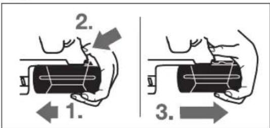
AkkymyIaTOpdb1 11 dbfapy:
AkkymyIaTOpdbIeNkTpKypaIbIyTtKaCbHaKapcbIbafblTa 6acbln(1.)awy nepheciH 18(2.)6ipdeBacblh3.
AkkymyIaTOpDbIeKTp KpaIbHaH KbI3blcI3blK KeiHReHwe WbIrapbHb3 (3.).
Amy nephecin 18 kHe 6acbIn aKKyMnyTopbI ToNbIK WbIfapblb3.
AkkymyTOp 3apJdTany Kyn HnHkAtopbI
AkkMyIaTOp 3aprTany Kyi HnKAtOpbHbH 20 yu Xacbl JapkDIOBbl AKKMyIaTOp 11 3aprTany KyIH KepeTei. Kayinc3ik CandpbHaH 3aprTany KyIH cypa TeK 3JIeKtp KpaBbH ToK TaBn OpbHday MyMKIH.
- 21 nephecin 6acbin 3apnkykepceinei (akymnyatop ybfapbnfah 60ncda mMmKIN).5cekyndancoh 3apntany KyinHdkKatops e3i ewdi.
170|Ka3aKa7a
KaeknIH MeHTKMeHDeTINReH Kymbc aHaJIbIMapCaHbIyWIn KY
BypaHda yuTbIKTapbIH opHaTy (N cypetin KapaHbI3)
3NeKtp KypaBbH CombH/6ypaHdaFa TeK eWipinre H Kynde canbHbI3. AHaNaTbH aImaNbi-caImaNbi acnantap Tyci n KeTy i MyMKH.
BypaHa yuTbKapbH naDnAnahy uWIn aM6ean yCTaFbI 31 SDS-plus-acn an npToHbIme (KepeK-Ja6bIbTap) KepeK 60anabl.
TytKaHbHcAblHaTbHUbH Ta3aJAn, a3aJn MaJNaHbI3.
AHaHMaIbI aMb6an yCTaBHTbI KypAnbIbIeKiTyOpHbIH aBTOMaTbI TypIe 6eKITINReHHeCaJIbHbI3.
-0M6e6an yCTaftbIHTbI TaTbIn, bekitinyi TeKcepiH3.
-YCTaftbIwka WypynTapdb6ypan 6eKiry 6HtacbiH canblb3. Tek Wypyn 6acbHa JapaaiTBH KOHdbipMa 6HtanaPbI naDanaHbHb3.
- ΑM6e6an yCTaftbTb any yuH 6eKiTy TnKeciH 5 apTKa KblNkblTbHb3 XHe A6e6an YCTaftbTb 31 KypanDbI 6eKiTy opHbHaH WbIfapbHb3.
DipindeytdomeHdety

Vibration Control
Kipikipme dipinneyidemehdery dipinneyepki kemitei. Softgriff kantamacbi cibpHaay kayinih TMeHdetin 3Nektp KpaIbIHbIH,dybIC 6yblpIbIbI MeH OHaIIbIFbIH KAMTaMa eTei.
AkkymnyTopbI OHTaIIbI naIaNanHy TpyaIbI Hcyckaynap AKKyMnyTopDbI CyblkTbIKTapdAn HKeHe bINFaIHaKopFaHbI3.
AkkymyIaTOpIbI TeK-20°C...50°C TemnepaTypa ayKbMbHHa caKaTbH3. AkkymyIaTOpIbI Xa3da KeIiKe KaIbIpMaHbI3.
AkkymyIaTOpdbH KeJeTeTy TecirH Kymcak, Ta3a XHe Kypfak. 1eTKaMeH MyKnT Ta3aHaBb3.
PaindaIahy Mep3imH aTapbIaTaN Kbckapybi
aKMyIaTOPdbIH eckipreHH XaHe aybIcIpy KepektiriH
6inipedi.
KokbiTapblKaetaeHcyTypaBlHyckaynapblOpbHaBhl3.
TexHnKaIbIK KytIM XaHe KbI3MeT
Kb3MeT KepcTeY XaHe Ta3anay
AkkymyIaTOpbl3JeKtp KypaIMeH Ke3 KenreH KymbIcTapbl (MbICaNbl, OPhATy, KbI3MeT KepCETy, T.6.) 6actay anblHa, coHdai-Ak, JeKtp KypaIbI TaCbIManDlay XHe CaTAY Ke3iHne WbIFapblB13. Ke3eNcoKocblfHaJaXkapakatany Kayni 6ap.
Dypbcxheceimdiicteyyuih3neKtp Kypanme Hkndetkiu TecikTi Ta3a yctahb13.
3aKbIMdaFah WAnHnH CaKaTbIH 6yKbTpMa 6ipDe H anMaCTbIpybIky KaXeT. OhBi Kbl3MeT KepeTy We6epxHaacBHaOpblDay YcbHbIaNbl.
Kypal6eKty opHbH 3 ap naJaHaHydAn KeiH Ta3anaHbI3.
TybHybIfa KbI3MeT Kepcety XaHe naDanaHy Kehectepi
KbI3MeT KepcTeY ue6epxahacbI eHIMdi JxHDey XaHe KyTy, coHdai-ak KocankbI 6eIweKteP typal cypaKTapFg kayan bepei. KaKeTTI cbl36anap MeH KocankbI 6eIweKteP typal bAknapaTbMbHa MeKeHxaJaTaTabac3:
www.bosch-pt.com
KeHec 6epywi Bosch kbl3metKepnei eHimdi naaIaNanay XHe onapdbH Kocankb6eWekTepi TypaI cypaTapbHb3Fa TnHaKaTbJkayan 6epedi.
CypakapkoXeHKeocankb6oWekTepeTancbpbc6epy Ke3HMeMHdTeTI TpyeEHIMIH3aybITbIKTaKaTHaCbHdaFbl 10-caHbIeHIM HEMPiHka3bHb3.
EHnpyti TanaTapbMeH HopMaIapbHbH CaKtanybIme HneKtp KypalbH XeHDey XeHe Keinii Kbi3Met Kepcety BapbIK MemLeKeTepayMaFbHnDa TeK "Pobep T Boi"
HpmaBik Hemece ABTOPiHaunHaH Ka3Met Kepcety
OpTaBkTapbHda OpbIHdaJaBbl.
ECKEPT! 3aHcb3XKoIeMeh AKeiHReH OHIMpePi naIaNanAHayinti, DeHCaybIbHbIb3Fa 3nH KeTIpyi MymkIn. OHIMepDi3aHcB3J Kacay XHe TaPaTy kIMuINIK XHe KbIMbICTbIK Taptin 60bHHa 3aHMeH KydanaHaDbI.


174 Romana
Ka3aKCTAH
TybHybIapFaKeHec6epyXHeWafBIMapIbI Ka6blday optaIbIfl:
"Po6epT Bow"(Robert Bosch) KLIJC
AMatbIK,
Ka3akCTah Pecny6mKacbl
050012
Mypar6aebK.,180y
"TePmec"50,7Ka6aT
Ten.: +7 (727) 331 31 00
_aKc: +7 (727) 2330787
E-Mail: ptka@bosch.com
CepBnCTIK Kbl3Met Kcpcty optanbIKTapbi MeH Ka6bnay nyHKTePiH MeKeH-XaJIb TypanbI TOnbIK XHe 03Ekl aKnapaTb Ci: www.bosch-professional.kz pecmN caTTaH ana anacb3
TacbImaIay
BvHnHn-HoHbIKaKMyJrTopnap KayiTI TayapnapFa KOblnTaBH TaanTAPfCa BonyBeKepe. PAnDaNaHyu bI aKKMyJrTopnapBk KeWeDe KcBIMwA KyKaTTapCb3 TaCmMaIaNaiAbI.
YiHui TynfanaP (Mbicanb, Oye KeNirI Hemece Xibepy) opamara XaHe Mapkanapra KOnBnAtbH apHaNb TaanTAPdb CaKtay Kepe. Xibepyre daBihay Ke3Hne Kayinti KykTep MAmahhna xa6apnacy Kepek.
AkkymyIaTOpbI KOpNcbl 3akBmdaIHaB 60nca fHa 66eipH3.AuBk Tynicnepepi KeinimdeH3KHe AkkymyIaTOpbI opamada Ko3FaMaHbHdau OpaHbI3. KaKet 60nca, KocBIMua yTTbIkepeKepeepdi cKaTaHbI3.
Kadere kapaTy

3NeKtp KypaIapdb, aKKyMnyTOpnapdb, KepeK
KapaKTapdb JxHe opay MaTePnaIapbIH
3KoIOnrIbIK TpyfdaH dYpbic YTNIN3aUyNlayra
Tancbipy KepeK.

3neKtp KypalapdbI JKeHe aKKyMylTOpnapbl/6batapeHnapblYi KOKbcHa TactamHbI3!
Tek kaHa EO endepi yuin:
Eypona 2012/19/EU epejekci bohuiwa japaMcb3 3JIeKtp KpaIapbl Jhahe Eypona 2006/66/EC epejekci bohuiwa 3aBIMdaFah Hemece ecki akkymyIaTOp/ 6aTapeIaNap 6eK KHaHbIN Kdere japaTbNyIkaKeT.
AkkymyTopnap/6aTapeenap:
JIHTHNIHOHNDbIK:
"TacbMaJday"rapaybHdaFbl,1746etihderiHyckaynapblOpbHdaHb3.
TexHHkanbIK e3repicTepeHri3y KkykbIbI caKtaNaIbI.
Româna
Service scule electrice
Strada Horia Macelariu Nr. 30-34, sector 1
013937 Bucuresti
He oTBapnTe akymnatophata 6atepe. CbueCTByBa ONaCHOCT OT Bb3HnKBaHe Ha KbCO CbeDINHEne.

IpeNa3BaIte aKymyIaTopHaTa 6aTePnIaOT BnCOKITemNepaTyPh, HAp. BCNeIcTBHe Na IpoDbIKN-TEHNO N3IaIaHe Ha InpEeTHa CbHueBa CBETnHa
HIN OFbH, KaKTo H O T BODa N OBLaXHBAHe. CbIeCTByBa ONaCHOCT OT EKcIIIO3HA.
Pn NOBpeKdane H He npabHna ekcnnoataa on Oky MynatopHATA 6atepHn MoT a c ce OTenr napn. PpO BETpe NOMEeHHeTo n, Ako CE NOUYBCTBaTe Hepa3- NOnoxHen, NoTbpCte NEkapcKa NOMou. Napte MoT a da pa3dpa3Hrt dnxAteHNHTe nbTuHa.
H3non3BaIte akymyataopHata 6atepna cAmO ceneKtponHCTpymEnTa,3a K0To e npedn3HaueHa.CamO taKa TRe npedn3eHa OT OnacHO 3a He rpeTobapBaHe.
PpeMeTH cOCTPN PB60BE, HApN. NpOnH Mn OTBePTKnn CHINNH MExAHNUH Bb3dEChTBMa MoRAT da NoBpeIaKymnatopHata 6atepna. MoKe da 6bJe ppeIN3BnKaHO BbTpeuHo KbCO cBeHNHeHne nakymnatopHata 6atepna MoKe da ce 3ana, da 3anyu, daeknlonpa nn da ce npperpee.
Onncahne Ha npodyKta N Bb3MOX-HoCTHTe My

Ipooyete BHHMaTeHNO BCnKnyka3aHn. Hecna3BaHeTo Ha npBedeHInTe No-dony yKa3aHnMoKe DaIOBeDe IO TOKOB yDap, noKap n/nn TeKKn TpaBMn.
MOnIa,OTBopTe pa3bBaUataCe Kopuca CnHyprnte H,IokaTo YeTeTe pbKOBoCTBOTo 3a EKcNlOaTaunr, RaocTaBeTe OTBopeHa.
PpeHa3NaueHne Ha eNeKtpOnHcTpymeHa
EneKtpoHnCTpymEn e npedHa3Naueh 3a yIapHo np6bHaBe B6ToH, 3IaIapn H KAMeHNMaTePnaHn, KaKTo H 3a NekO KbptHe. ToI cbTc Taka e nOxOJa3 a 6e3yApHn np6bHaBc H bIbPbeCN MaTePnaHn, MetaHn, KepamuHn MaTePnaHn I nIactMacn. EneKtpoHnCTpymEn t c eNEKtpoHn ynpabHe Hne I DaCn H IraBa NocKa Ha BbPTeHc ca nOxOJaun CbTa TaKa H 3a 3aBbVaHe/pa3BbVaHe.
H3o6pa3eHH enEmeHTN
HomepnpaHTo Ha enemEnTe Ha eneKtpOnHcTpymenta ce OTHACdo H3o6paXeHNrTa Ha cTpaHnTe CfHpyPte.
1 NaTpoHHNK 3a 6bp30 3axBaUaHe (GBH 36 VF-LI PIus)
2 Cmehem NaTpoHHNK SDS-plus (GBH 36 VF-LI Plus)
3ПатроннкSDS-plus
4IpoTINBONpaxOBAKaNaaKa
53actonopraaabaBtynka
6 3actonopraBaHe Ha CMeHReMn NaTpoHHK (GBH 36 VF-LI Plus)
7 CnCTema 3a noIgIbIaHe Ha Bn6paunHe
8 IpeBknHouBaTeI 3a IIOcOKaTa Ha BbptHe
9 PbkoxBaTka (H3oInpaHa nOBpXHOCT 3a3xBaAHe)
10IyckOBIpeKbCbaa
11 Akymyntopna 6aetepna
12 Bytoh 3a ocbo6oxdaBaHe Ha npebKIOUbaTeNa,ya-pn/CnpaHa BbpteHTo
13 PpeBknUbaTeIyDapn/CnnpaHe Ha BbpteHTo
14Pa6oTHa lamna
15 Bytoh 3a perynipae Ha dbb60HHnO orpaHnHTe
16 CnomaraTeHa pBko XBaTka (N3oInpaHa noBbpxHocT 3a 3axBauahe)
17 DbN6OuHHeHOrpaHHuHTen
18 Ocbo6oKDaBauN 6byToHn 3a akyMnyaToPnHa7aTepeHn
19 CBeToOnIOI 3a TemnepaTyprHnKoHTpon
20 INdkaTOp 3a cbCToHHeTo Ha akymnatopHaTa 6aTepe
21 Bytoh 3a nokaBaHe Ha cTeeHtHa 3apeHocT Ha akyMynaTopHpTa 6aTePn
22 OcnrypntenE BnHT 3a NaTPOHHK CbC 3b6eH BeHeq (GBH 36 VF-LI Plus)
23 PatoHHK CbC 3b6eH BHeue (GBH 36 VF-LI Plus)
24 OnaKa SDS-plus 3a narpOnHHka (GBH 36 VF-LI Plus)*
25 Theo 3a natoHHnka (GBH 36 VF-LI Plus)
26MapknpaunHnade3n
27 KIou3a natoPOnHHka (GBH 36 VF-LI Plus)
28 PpeHa BtynKa Ha NaTpoHnKa 3a 6bp30 3axBauaHe (GBH 36 VF-LI Plus)
29 HenoBnKa BtynKa Ha NaTpoHHka 3a 6bp3o 3axBaauHe (GBH 36 VF-LI Plus)
30 PpeBknOyBaTeI 3a cnCTeMaTa EPC (Electronic Precision Control)
31YHnBepcAHO rHe3do c onaWka SDS-plus*
*N3o6pa3eHne H a hpyrHpe H oONcaHte DOnbHNHTEN nPncNoC06NeHH He ca BKNIOeHH B cTaNAPTHa OKOMnNEKTOBKA Ha
ypeHa. N3eepnatene H cINCb K Ha dOnbHNHTenHtne npcnocO6NeHH MoKeTe Da HameHPe CTOBETHO B KaTAnora Hn 3a DoBnHnTENn PnCNOco6NeHH.

186|Былгарский
Texnueckn daHHN
| Пларфоратop | GBH 36 V-LI Plus | GBH 36 VF-LI Plus |
| Каталожен Home | 3611 J06 0.. 3611 J07 0.. | |
| Рergулиpane на скорocта на вьртени | ● | ● |
| Спиране на вьртени | ● | ● |
| Вьртени на скорoctega/наляво | ● | ● |
| Смени патонник | - ● | |
| Номинално нашиpenенье | V=3636 | |
| Номинална консуmp irreно мошноct | W 600 600 | |
| Чеб耗费 на удariце | min-1 | 0-4200 0-4200 |
| Енера по сокорст на вьртени | J | 3,2 |
| Номинална скорost на вьртени | min-1 | 0-940 0-940 |
| - Вьртени наскогло | min-1 | 0-930 0-930 |
| Гнед do заразовени Истру金融市场 | SDS-plus SDS-plus | |
| Диаметер нашикatingа на вала | mm 50 50 | |
| Мakс. Диаметер на п探测овени OTВор.: | 28 82 13 30 | |
| - Бетон | mm | |
| - Зидаши (с куха борковая) | mm | |
| - Стomanа | mm | |
| - Дьравесни мateriated | mm | |
| Маса сьлално EPTA-Procedure 01:2014 | kg | 4,0/4,51) 4,1/4,61) |
| Долустima Tempeратура на okолна т creда | °C | 0...+45 0...+45 |
| - пи зарочданe | °C | -20...+50 -20...+50 |
| - по врeme на скота2) и за склади rupevi | °C | GBA 36V ... GBA 36V ... |
| пренихителни akumylatordniбateурni | AL36... AL36... | |
| пенихителни за干嘛и устroduства | GAL 36... GAL 36... | |
1)B3aHbHcMnOCTOTnH3NON3BaHaTAtkyMylatopHa6aTePnA
2)OrpaHnueHa npOnBaOIOHTeHNOCT npN Tmnepeatypn < 0^
TexnueckntepnapametnpcaonpeleneHcakymnatophata6aepnra,BknoeHaBOKOMIKeKTOBkata.
HhopmaaHa 3a H3bYBaH Wym Hn Bn6paun
CTOnHOCTHTe Ha H3JIbYBaHHa Wm Ca ONpeDeHn CbflacHO EN 60745-2-6.
PaBHnIeToAHaTeHepnpaHnOteNekTpoHHCTpyMeHTaWym
obHKHOBeHo e: paBHnIe Ha 3ByKObTO HAnraHe 90 dB(A);
paBHnIe Ha MouHocTa Ha 3Byka 101 dB(A). HeonpeJeHcct K=3dB.
Pa6oTeTe c yM0aIyuHTeHn (aHTnFOHn)!
TbHnata cToHnOCT Ha Bn6paunHe (BeKTopHaTa cyMa nToTne HapnPaBnEnH) n HeonpeDeneHocTt Ka onpeDeneHcBrlacho EN 60745-2-6:
Ydapno npo6BnBe B 6eToH: a_h = 14,5m / s^2,K = 1,5m / s^2 KbptHe: a_h = 9,5m / s^2,K = 1,5m / s^2
Ipo6nBaHe B metan: a_h < 2,5m / s^2 K = 1,5m / s^2 3aBnBaHe/pa3BnBaHe: a_h < 2,5m / s^2 K = 1,5m / s^2
IocouheHOTOBTOBApbKOBOCTBO3aekcnloaataua paBnue Ha rtehepnpaHTe Bn6paunE h3mpeHo cbrnacho npoeUypa,ctanaptn3napaHbEN 60745,IMoKeJa cnykHa cpaHBaHe Ha eJekTPOINHCTpyMeHn edHN Cpyr.To e noXOdaIIO cbIIO 3a ppeDbapntEnHa opneHTnpOBByHa npeceHKa Ha
HaTOBapBaHeTo OT Bn6paun.
IocouehOTO HnBO Ha rehepepaHNTe Bn6paun e npedctaBnTeHNO 3a Hau-ueCTO CpeaHNTe PpINOKeHnHa H enekTPOHNCTpyMeHTA.AkO abue eNEKTPoHNCTpyMeHTb 6bde N3NON3-BAH 3a DpyrN DeHIOCTN, C pa3NIuHn Pa6OTn HNCTpyMeHTn INN Be3 Heo6xOIMTO TexHuecKO obCnyXBaHe, HNBO To HA Bn6paUNTE MoKe Da ce pa3NIuaba. TOb 6n MOrNo Da yBeHmN 3HaUnTeHNO cyMapHO To HtOBapBaHe OT Bn6paUN Bnpoeca Ha pa6ota.
3aTOHaTnPpeHcKaHa HATOBapBaHeToOT Bn6paun Tp8Ba Da bDaT BImaHn PneBnDn NepnoDnTe, B KOnTO eNKeKtpoHnCTpyMeNTbE hKnIOueHnn PaobTH, Ho He ce non3Ba. ToBa 6n MoIIO 3NaHTenHO da HaMaJInc CymapHTo HATOBapBaHe OT Bn6paun.
PpeINCBaIe DoBbHHTeHH MepK3a npEpa3BaHe Ha pa6oTeuHa c eEeKTPoHnCTpyMeHTa OT Bb3JeHCTBHeTo Ha BN6baUHHe, HApHmEP: TexHuecko 0cCnyKBaHe HeneKTPoHnCTpyMeHTa n pa6oTHHe HHCTpyMeHTn, PndbpKaHe Ha pbTe ToNN, Zeceb6pa3Ha opraHn3aHa Ha p6oHTHe CTbKN.
BbIrapckn187
MOnTupaHe
3apexkane Ha akymyataopnata 6aTePn (BnKTe pR.A)
H3no3BaIe cmo Hkoe OT 3apdHnTe yctpoCTBa, nocouEHn HA cTpaHnCATA C dONbHnHTenHnTE npncno- co6neHn. Camo Te3n 3apdHn YcTpoCTBa Ca IOnxOJn 3a H3no3BaHata BbB BaHn eNeKtpOHnCTpyMeHT IIN TNEBO-NOHHa akymylatopHa 6atePn.
YnbTbAe: AkymyNaTOPHATA 6aTePnCe DoCTBa YactNuHO 3apeHeHa.3a Da DCTHrHETe NbHnKa nauTeHa akymyNa-Tophata 6aTePn, PpeN PbBoto HnIOn3BaHe r 3apeTe DOKpaB 3apAnHO yCTPOICTBO.
JInteBO-IOHHATA akymnatoPb 6aTepeHnMoKeJa 6bJe 3apeKDaHa NO BcKO BPeMe, 6e T0Ba Da CbKpaUaBA DblrOtpaHocTt Ha. IpeKbCbaHe Ha 3apeXdAteo CbIoo He H BpeHnJIITneBO-IOHHATA akymyAtopHa 6aTepeHn e 3auHTHe cpeuYnbHO pa3peXdaHe OT eneKTPOHNHMOyn ,Electronic CellProtection (ECP)".Ipn pa3peXdaHe Ha akymyatopHa 6aTepeHn eNEKTPOHNCTpymENTbT Ce N3KNIOUBy O t npEnnaehpeKcbCaY:Pa60THnT INCTpymENT cInpa Da ce DBHXN.
CneI aBOMaTHUHOT N3KIOUOBAHe Ha eNEKTPoHNCTpyMeHTa He npOdbNkBaAte Da HATNCKATE NyCKOBn IpeKbCBa. AkymnaTophata 6atepma Moke da 6be nOBpe-DeHa.
I3BaXdAne Ha akymyNaTOpHata 6aTePnA
Akymynatohpata6atepna11e cDBe cTeeneHnHa3axBaunaHe, KOeTO Tpa6Ba Da npeDoTbPaTH nadaHTo I npH HtNcKaHe NO HEBHMaHHe Ha 6yToHa 3a ocBo6xDaBaHe Ha akymynatoP Hata6atepna18.Korato akymynatohpata6atepna e nocta Beha B eneKtpOnHCTpymEnTa, ce npNbpbKa B HyxHa tno3u HAOTnykHa.
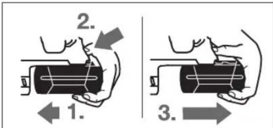
3a n3BaKaDaHe Ha akymyNaTOpHata 6aTePnA 11:
IpnTHcHeteakymytaTophata6aTePnKaKpaKaHaeneK TPOINHCTpyMeHTa(1.)eHOBpeMeHHoHaTCHETeOCBO- 60kDaBauN6byToH 18 (2.).
I3nbpnaTe akymyaTo npHaTa 6aTepeRn OTeNkToPnHcTpymeHTa,doKaTO ce NOKaKe YepBeHaTa Hbua (3.).
HaTnCHeTe ocB06oJdaBaIaIg 6byToH 18 oIe BeIbIg I n3- DbpnaIte akymyIatopHata batepna.
CBeTINHeH HnDnKaTop 3a CbCToHHeTo Ha aKymNaTopHaTa 6aTePn
Tpnte 3eneH CBeToNDHOa 20 NOKa3BaT CTeNEHa Ha 3apeHeHocHT Ha akymyNaTOPHATA 6aTePn11. IpopaN CbO6paKeHHa 3a 6e3oNacHcT npOBepkata Ha CTeNEHa Ha 3apeHeOCT Ha akymyNaTOPHATA 6aTePn MoKe DaCe H3BbPwBa CaMo KOrato eNeKTPOHNCTpyMeNTb E B NOKoI.
HaTnCHete6yToHa21,3aJaBnIteCTeNEHa3apeHcHtHaakymyIaTOPHa7BaTePn(Bb3MOKHOeCbIoo INpHnH3BaDeHaakymyIaTOPHa6BaTePn).CBeTOmOJTe yracBatABTomAtuHoCneI npHb.5cekyHn.
| Сbvетонд Каццтет | |
| Henpeкьсато CBteテе 3х зelenу | ≥2/3 |
| Henpeкьсато CBteテе 2х зelenу | ≥1/3 |
| Henpeкьсато CBteテе 1х зelenу | <1/3 |
| Могаши CBvetлиna 1х зelenу | peзерва |
Ako CneI HaTnCKaHe Ha 6yToHa 21 He CBETn HHTO eINH CBTOIHO, akyMynatopHata batepe n nobpeHa n Tp8bda 6b-De 3aMeHeHa.
IbBpeHa Ipoceca Ha 3apeXdahe TpIte 3eHn CBToOnOda CBETBaT NocleOBaTeNHO H CneI TOBA yraCBat. Korato TpIte 3eHn CBTOOnOda 3aONuHaT Da CBETr HnpeKbChaTo, AkymyIaTOPHaT a6aTePna e 3apeHea. PIn6I.5MHyTu CKe KaTO akymyIaTOPHaT batePna ce 3apeHn HAnbIHO TpIte 3eHn CBToOnOda yraCBat.
CnomaraTenha pbkoXBaTkA
H3nON3BaIte eNEKTPoIHCTpyMeHTa CH cAMO C MOHTpaHa cnOMarATENa pbkoxBaTKa 16.
HaKaNaHHe Ha cNoMaRaTeHnHaTa pbKoXBaTka (BHXTe pHR. B)
MoXeTe Da NoCTaBtE cnOMarATEHATA pbKoXBaTka 16 npakTnueckn B npon3BOHnA no3nur, 3a da CNOCHypnte yDObHa 6e0Na cha no3nur Ha pa6ota.
3aBbptTe DoJHATA pKoXBAtka Ha cNoMaTaTeHATA pKoXBAtka 16 B NocOka, ObaPaHa Ha YacOBHKnOBaTa CtpEnKa Hn HAKIOHete cNoMaTaTeHATA pKoXBAtka 16 B XeJaHaTa No3uHa. CnTo ToBa 3aterHeTe OTHO Bo DOnHata pKoXBAtka Ha cNoMaTaTeHATA pKoXBAtka 16, KaTo n 3aBbPTTE NO TOCOka Ha YacOBHKnOBaTa CtpEnKa.
BHHMaBaIte 3axBaIaIaIaIeHTa HcNoMaIaTeHnHa pBkoB-BaTKa Ia nonaIHe B npEbnIeHna 3a cIeT a KaHaN B Kopnyca.
H360pHa na npoHHKa pa6oTHHe HcTpymEnTn
Pn ynapHo npoBnaHe n KbptHe ce HxKdaTe OT NHTpyMeHTn c OnaAka SDS-plus, KOntO ce NoCTABT B NaTPoHHKa SDS-plus.
3a6e3ydpno np06nBaHe B dpBecch MaTePhaHn, Metann, KepamuHnMaTePhaHn nPiactMaCh, KaKTo H npn 3aBnBaHe/pa3BnBaHe Ce n3IOn3BaTnHCTpyMeHTn, YnTTO onaKa He eSDS-plus (Hanp. CbpEna c uInnHnpuHa onaKa).3a Te3n INhCTpyMeHTn Ce Hykdaete OT natpoHHNk 3a 6bp3o 3axBaHaHe, pecn. NaPONHHK CbC 3b6en BeHeq.
MOnTHpaHe/JeMOHTpHaHe Ha naTpoHHka Cbc 3b6eH Beneu (GBH 36 VF-LI Plus)
3a da moKete da pa6oTnTe c HnHcTpymEnTH 6e3 onaWka SDSplus (HaNP. CbpeNa c uninHnpuHa onaWka), Tp6Ba da MOHTnPate NOxOJaN NaTOHHNK (NaTOHHNK cbc 3b6eH BeHeu, pecn. NaTOHHNK 3a 6bp30 3axBaUaHe, He ca BKNIOueHN B OKOMNIKETOBkata).
188|Былгарский
MOHTHPaHHe Ha natoHHKa Cbc 3b6eH Beneu (BHXTeΦnR.C)
HabnTe onaikata SDS-plus 24 B natoHHK Cb3 b6eHNBEHeu 23.3actonopete natoHHKa CbC 3b6EH BeHeu 23 C BNHTa 22.BHMabaTe, ochypntenHHTBNT e c naBa pe36a.
MOHTnpahe Ha natapoHHK cbc 3b6eH BHeue (BHXTe pHr.C)
-Поунichte Края Ha onaшkaТа И Г смжte Лк.
-BkapaTe natoponHHka Cbc 3b6en BHeue c NoctaBeHa OnaWka Cbc 3aBbPtaHE B THe3dOTo, DOKaTO ce 3axBaHe aB- TOMaTHUHO.
YBepete ce,ye natoponHHKbT Cbc 3b6e HBeHe e 3axBaHAT 3dpabo,KaTO rO h3dbpNaTe.
Demontnpahe Ha natpOHHK cbc 3b6eH BHeue
IpeMeCTe 3actOnOpRAaTaBtynKa5Ha3aHn3BaTe NaTPOHHKa CbC 36beH BHeue 23.
JemOHTHpaHe/MoHTnpaHe Ha CMeHReMnnaTPOHHK (GBH 36 VF-LI Plus)
NATPOHHKbT SDS-plus 2 MOxE neCHO da 6bde 3aMeHeH C BKNIOUeHn BOKOMIIeKTOBkata NaTPoHHK 3a 6bp3a 3aMHa 1.
DemOHtpaHa cMeHReMaNn NaTPOHHK (BHXTeΦHr.D)
I3nbpnaTe 3actonopraa npbCTeH 6Ha cmeHReMa NaTPOHHK Ha3a, 3aDpbKTe ro B Ta3n P03uN H3DbPnaTe NaTPOHHKa SDS-plus 2, pecn. NaTPOHHKa 3a 6bp-3a3amHa 1 Hanpei.
CneJeMoHTpaHe na3eTe CMeHReMnnaTPOHHK OT 3a-MbpcaBaHe.
MoHTHpaHe Ha CMeHraeMn NaItpoHHK (BHXTeΦHr.E)
H3no3BaIte cmo npncnoc6neHn, npedHa3haueHn 3a BaWn moeEneKtpOnHcTpyMeH n cbueBpeMeH H BHHMaBaIte 3a 6pOHa MapKnpaUHTe Ha3Dpe3N 26. DonyctHMo e H3no3BaHeTo cmo Ha CmHemaH NaTpOHnHi C Da Hn TpM aOpKaUHn HApTeA. AKO CTo3n EneKtpOnHcTpyMeH CE H3no3BA HeNoDxOJaC MEm NaTOPHnIK, paOToHrT INCTpyMeH MoKe Da NaHne No BpeMe Ha paOta.
IpeHn da noCTaBtme CMeHReMn NaTpoHHNK,ro NOuHCTeTe HCMKeTe NkOOnaWKata MY.
-3ax BaHete natpOHnKa SDS-plus 2, pecn. natpOHnKa 3a 6bpr3a zamHa 1 c qanata pbka. BkapaTe Cmehemna naTPOHHK Cbc 3aBpTaHe Ha rHe3dTo 25, DOKato ycTeHTe OTHTINBO PpeuPaKaBaHe.
CmeHnEMHnT nAtpoHHNK ce 3aCtONoPBA aBtOMaTHNO. YBepeTe ce, ye natoHHNKbTe 3axBaHaT 3dpBO,KaTO rN3DbpNaTe.
CmHaHa pa6oTHnHnCTpymENT
IpoTbONpaxOBaKa KanaUka 4 OrpaHuaBa CnHNo IpoHnKBA HeTo Ha OTdEJIaNc Ce npk KbPteHe Ipax B NaTpOHHka. Ipn NoCTABHe Ha paBoTHHa HcTpyMeHT BHMaBaIte Da He NOBpeDIne npTbONpaxOBaKa KanaUka 4.
POBpeHa npOTnBONpaxoBA kanaKa TpR6Ba Da ce 3aMeHH BeHara. PpenOpbYBa Ce TOBa Da 6bJe H3BbPeHO B OToPn3nPaH cepBu3 3a eEnkTPOHNCTpyMeHTN.
CmHa Ha pa6oTHMa HhctpymeHT (SDS-plus)
IocTabaHHe Ha pa6oTe HnHcTpymeT c onaWka SDS-plus (BHXrE F)
C natoponHHNK SDS-plus moKTe Da 3aMeHrte pa6oTHnIHCTpyMeHT neCHO uyo6Ho 6e3 H3NoI3BaHe Ha cIOMaTaTeJIHNHCTpyMeHTN.
- GBH 36 VF-LI Plus: NocTabete natpoHHika SDS-plus 2.
- POnHCTeTe ONaWKATA Ha pa6oTHn HnCTpyMeHT NcMaKeTe JNEKO.
BkapaTe pa6oTHHn HNCTpyMeHT B nATPOHHNka CbC 3aBbP TaHe,doKATO 6bDe 3axBaHaT aBTOMaTHHO. - YBepete ce ue3 n3dbpnbAhe, ye e 3axbaHaT 3npaBO.
Cbrnacno npHHnna cn Ha deNCTBne pa60THNt HNCTpyMeH C onaoka SDS-plus e cbo6oDen. Nopadn TOBA npn BbpTeHe Ha npa3eHN XOg Bb3NHKBA padnAHO OTKIOHeHne. To obaue He ce Otpa3Ba HA TOHOCCTHa npoNBaHNA OTBOP, Tb KaTO npn npoNBaHe CBpeDnTo Ce camoUeHTPOBa.
N3BaXdAne Ha pa6oTe HnHcTpymeT c onaWka SDS-plus (BmXte fHyrpa G)
-Дрьн electaToOpRaUaTbTyIka 5Ha3aIиN3BaTe pa60THH INCTpyMeHT.
CmHa Ha pa6oTHHnHcTpymeHT (6e3 SDS-plus) (GBH 36 VF-LI Plus)
TocTabHe Ha pa60THH HnCTpyMeN (BHXTe FmrypaH)
YnbTbAe: He n3n0n3BaIte HNCTpyMeHTn 6eonaaKa SDSplus 3a ydpHO np6nBaHe nn KbpTeHe! Pnp ydpHO np6nBaHe n KbpTeHe INCTpyMeHTn 6e onaKa SDS-plus n naTpoHHKbT ce NobpeXdA.
- NocTabete NaTPOHHK CbC 3b6eH BHeue 23 (BnXTe, MoTHIpaHe/JeMOHTnpaHe Ha NaTPOHHKa CbC 3b6eH BHeue", CTpaHnca 187).
- Upe3 3aBbptAHe HAIRABO OTBOpTe NaTPOHHNkCa CbC 36BeH BHeue 23, TOnKOBa, Ye pa6OTnHrT INCTpyMeHT Da MoKe Da 6bDe NoCTaBEh.
BkapaTe KIOUca Ha NaIPOHHMa B npEHa3HaeHHe 3a CEtTa OTBOPHa NaIPOHHKa CbC 3b6eH BHeue 23 n 3aTER HETe INCTpyMeHTa paBHOMepHO, KaTO N3NoJIbaTe n TpHTe OTBOPa.
3aBpTepeBKnUcbAteIa ydapHO np6nBaHe/cnpaHa HbPteHTo 13 B no3nraTa, np6nBaHe.
DemOHTHpaHe Ha pa6oTHH NHTpyMeHT (BHXTe
3aBpTe BtynKaTa Ha NaItpOHnKa Cb3b6eHBeHeu 23 06paTHo HA yacOBnKOBaTa CTpeNkA C NOMOHTa Ha CneU nnnnnaPahn KIOU,doKATo pa6oTHnT HCTpyMeHT MoKe Da 6bde N3BaDeH.

Блгарский | 189
CmHaHa pa6oTHnHnHCTpymENT (6e3 SDS-plus) (GBH 36 VF-LIPlus)
IocTabaHHe Ha pa6oTHHa HcTpymeHT (BHXTeΦnJ).
YnbTbAe: He n3nOJI3BaIte HNCTpyMeHTn 6eONaWka SDSplus 3a ydapHO npo6BaHe nn KbpTeHe! Pnp ydapHO npo6BaHe N KbpTeHe INCTpyMeHTn 6eONaWka SDS-plus n naTPOHHKbT ce NOBpeKdA.
- IocTabete naTpoHHnka 3a 6bP30 3axBaUaHe 1.
3axBaHete Btynkata 29 Ha natpoHHnka 3a 6bp3a zamna. OTBopete NaTPOHHnka, KATO BbptIte npedHaT Btynka 28, DOKaTo HHCTpyMeHT MoKe da 6bJe NoCTaEB. 3aPbKTe Btynkata 29 N 3aBbptTepeHata Btynka 28 CnHIO B NOcOKata, yKa3aHa Cbc CTpeNka, DOkato UyeTe OTeTTNBO npeuPAkBaHe.
YBepete ce,ue HCTpyMeHTbTe 3axBaHAT 3npaBO,KaTO CE ONITate da ro n3dbpnaTe.
YbTaBe: Ako NaTPOHHKbTe 6nI OTBOpH DoKpa, npn 3aTgAHeTo My MoKe Da ce ue PpeUpaKaBaHe, 6e HcTpymenTbTa 6bDe 3actOnopeH.
B TaKbB Cnya3aBpTeIe npedHaT BtYnka 28 eHOKpaTHO
6baTHo Ha Nocokata, yKa3aHa CbC CTpeNk. CneToBa Na-
TPOHHKbT MoKe Da Ce 3aTBApR OTHOB.
3aBpTepepeBkIOuBaTeIe 3a yIapHO np6nBaHe/CnpaHe Ha BpTeHTo 13 B nO3nraTApnp6nBaHe".
DemoHTnpaHepa6OTHHHNCHTpymEHT(BHXTeΦHr.K)
3axBaHHe Btynkata 29Ha natponHHka 3a6bp3o 3axBauaHe.OTbOpTe NaIPOHHka Upe3 3aBpTaHe Ha npEHaTBAynka 28 B NocOKa, yKa3aHa cbc CTrpeNka, DOKaTO HCTpyMeHTbT MoKe Da 6bDe H3BaJeH.
IpaoxoynaBHe c GDE 16 Plus (dOnbJIHnTeHo npncnoc6neHne)
PpaxoBe,OTdJIuNcE npnOBpaBtBaHToHaMaTepeNaI KATOcbDbpKaaUOnOBO6OH,NKONBUNODe bPBeCnHa, MNHepaNIMetAlMOratDa6bDat ONaChN3a3DpaBeto. KOHTaKTbTdoKOxataINBNiWBAHToHaTaKNBaIpaXoBe MORATdaPneIN3BkAtaneprnHpeAeknn/INn3ab0nBaHnaHAnxATEHNTEbTNuaHa paBoTeunC eNEKtpOnHCTpyMeHNTaNNHAMnpaUnCe HApNIO6HO BOMnHaCNxCmHKAN3aTpHeHaNbPBeCHHa (Xpomat,KOHCEPBANTnIDp).DOnycka CeOBpaBtBaHTo HaCbDbPxuAn36eCT MaTepeNaIcAMoOT CbOTBeTHO6yueHHKBAHnDnupanNla.
-ПО ВБЗМоЖноCTИЗПОЛЗВАITE NOДХОДЯZA 3a 06pa6OTBaHHA MaTeHnA nCtEMa 3a npaxOyNabHe.
-0cnrypBaTe Do6po npOBetpaBHe Ha pa6oTHOTOMACTO.
- Pp e np b yBaCe H3NoI3BaHTeTHeMaCKac φnItp oRKnacP2.
CnazBaHTe BAniHNTe BB BaHaTa CTApaHa 3aKoHOBn pa3- nopeDn, BAniHn npn o6pabOBAHe Ha CbOTBeTHNe MaTepeHann.
M36aBaeHaTpynBaHe Ha npax Ha pa60THoMoCTO.
PpaxbT MoKe Iecho Da ce CaMOb3nMaMeHn.
3a npaxoynaBHeTo e Heo6xoJHMo noI3BaHeTo Ha GDE 16 Plus (He e BkIoueH BOKOMnEKeTbKaTa).
H3noI3BaHaTn paxocmykaKa TpR6Ba Da e npiroHa 3a pa-6oTa C o6pa6oTbAHn MaTePnA.
Ako npn pa6oTa ce otDena Oco6eH Bpehen 3a 3dpabeTo npax INI KAnHepeOReHen npax, H3non3BaTe CneuaHn3npaHa npaXOCMyKaUka.
Pa6ota c eIeKtpoHHcTpymEnta
IyckaneBekcnloataa
NoctabRHe Ha akymnatohata 6atepn
IocTaBeTe IpeBKnIOuBaTeTn 3a NOCOKaTa Ha BbptHe 8 BCpeDnO NOIOKeHne, 3a Da IpeDnA3Nte eNeKTpOHnCtpyMeHTA OT BKJIIOUcBAHe No HEBHMHaHne.
BkapaTe 3apeHata akymnatopHa 6atepna 11 ot3anB Kopnyca Ha eneKtpoHnCTpyMeHTA. PnTHcHeT akymnaT OPHATA 6atepna DOkpa,doKaTO uepeHnT npbcteh Ce CKPne H 6atepNtA 6bJe 3axBaHata 3dpaBO.
I03HnJra 3a nnaBHO BKnIOuBaHe H OOrpaHnueHa CKOPOCT Ha BbPteHe
IpeDna3eH cbeHNHTen
Ako pa6oTHHnHnCTpyMeHT ce 3aKlnHH, 3aDbHXBaHeTo KbMa Bana Ha eneKtpOHnCTpyMeHTa CE npeKcbBA. PpaH Bb3HNKBaUHTe pN ToBAsHa peakunTa DpBXTe eneKtpOHnCTpyMeHTa BHArH 3dPaBO C dBete Pbue H 3aemai Te CTabHnHO NIOJXeHne Ha TANOTO.
Ako pa60HTHnHCTpyMeHT ce 3aKNHH, H3KNHOte eNEKtpOHCTpyMeHT aOCBO6OTe pa60THnHCTpyMeHT. PIn BKNIOUbaHe Ha eNEKtpOHCTpyMeHTa, DOKaTo pa60THnHt HnCTpyMeHT e6NOKpHaB, Bb3HNKBat RoJEMNH peAKNUOHH MOMENT.
БьрзиЗклочвае (Kickback Control)
CnCTeMaTa 3a 6bp3o H3KIOUBaHe (Kickback Control) ocHrypRaNo-0obbp KOHTpon Ha eNEKTPOINHCTpyMeHTa. PInBHE3aHNO H HepeDBeIDHO 3aBbPtaHe Ha eNEKTPOINHCTpyMeHTa OKOIO OCTa HA CBPeIIOTo eNEKTPOINHCTpyMeHTb Ce H3KIOUBA aBTOMATNHO.
3a NOBTOPO BKNIOUBAHe CHeTe NyCKOBnI PpeKbCbaN IHO HATNCHETo OTHBO.
PexmbT ha 6b30 3apeXdaHe ce yka3Ba ype3 Mnahe Ha pa5oTHata lamna14 Ha eKTPoHnCTpyMeHa.
Bb30To H3KIOUBaHe ce 3aDeIcTB caMo aKO eNEKtpOnHCTpyMeHTbPa6OTn HA MaKCHMaHa cKOpOCT Ha BbpTeHe HMOKeJa Ce BbPTN CBO6OHO OKO NO OCTHa CBpeDnTo.
CBeToNDo3aTeMnepaTypHnKoHTpon
UepBHeHrCTCBToND3aTemnepaTyPhNkoHTpO19Noka3Ba,ueakymNaToPHaTa6aTePnHnEeKTPoHHoTOpYnpaBHeHne Ha eektpoHnCTpyMeNTa (npuNoCTabeHa akymyNaToPHa6aTePn) He ceHAMnPbONTHMaJIHHnTeMnepaTpeHnAna3OH.B TaKbCnyAeKTPoHHCTpyMeHbT He paBoTH B06ue HnPaBOThc HamaNeHaMoHocT.
Temepatypeh KOHTpon Ha akymyataopnata 6atepna:
-Пи NOCTABHHe Ha aKymaNaTOPHa 6aTePnB 3apdHTo yctpoIcTBO cepBeHNrT CBeTOINoD 19CBETN HepeKbCHA To: TEMepaTypaHa Ha aKymaNaTOPHa 6aTePnE H3BbH DonyctHMnI dHa nAaONoH O 0^ Do 45^ N aKymaNaTopHa 6aTePnHE MoKe Da 6bDe 3apeKdaHa.
UepBHeHrT CBeToHO19 MHa pN HaTHcKaHe Ha 6yToHa 21 Hn Ha NycOBnI PekbCbau 10 (pNIOCTaBeHa akyMynatopHa 6aTePn): Tempepatypata Ha akymnatopHaTa 6aTePn E h3BBn DOnyCTHMn pa6oTeH dHaana3OH.
- PnTeMnepepatya Ha akymyNatopHata 6aTepeHn HAD 70^ ENEKTPoHNCTpyMeNTbT N3KNIOUBA, DOKATO Temnepepatpata Ha akymyNatopHata 6aTepeHc Be BbpHe B ONTHMaHnHa nanaOH.
Tempepatyeh KOHTpon Ha eneKtpoHTo ynpaBHeHa eneKtpoHCTpyMeHTa:
-Пин�ИССКАне�псOKВИЗпpeкьСвач 10�ерБEHNT CBToIHOID 19CBETN HePpeKbCHaTO:Tempepatypata Ha eNEKTPOHHTO ynpabJIeHne e no-Manko 5°C nIn nobYe or 75^
-Придостигане на Tempepatуранад 90°C eeneKtpoHHoto
Управлике на онлайнстypedумаю КИКИчьа,ДOKА-
То Tempepatура наднда ДО дОустмгдддддддддддддддддддддддддддддддддддддддддддддддддддддддддддддддддддддддддддддддддддддддддддддддддддд徳
Yka3aHna 3a pa60Ta
HactpoBaHe Ha Dbl6oUHATA Ha np06nBaHe (BHXTe fHypMa)
C nomouta Ha dbnboHHHnOrpaHHHTe 17 npedBapntenHO moke da 6bde yctaHOBeHa dbnboHHata Ha npo6BaHe X.
HaTnCHETe 6yToHa 3aIbIbOuHHHnOrpaHnHTe15 nocTaBete OraPauHnHTe1B IHe3DTo B CnOMaTeHnHaTa pbKoXBaTKa 16.
HarpaneHaTaNobbpxHOCT HaDbNboHHnO rpaHHnTe17 Tp8Ba da e o6bpHata Hany.

Блгарский | 191
BkapaTe pa6oTHnH INCTpyMeT c onaWka SDS-plus do ynop B natoPOnHHKa SDS-plus 3. B npOHTBEH cnYauB b3- MoXHOCTTa 3a H3MecTBAHe Ha pa6oTHN HINCTpyMeT C onaWka SDS-plus MOKe Da IOBeDe Do HENpaBnHO Ha- CTPOBaHe HaNbIOOHnHa Na PpOBnBaHe.
N3dbpnaTeNb60uHHHnO rpaHnHTe TOnKoBa,ye pa3-CToHNHeTNO HAnpabNeHHe HA OCTa Meky BbpXHa CBpeINoTO Ha Nb60uHHHnO rpaHnHTeJa e paBHO Ha JeNaHata Db60uHHa HnpobuHnO TBOP X.
Yka3aHnHa 3a onTHMaHnHa pa6Ota c akymyNaToPnHa 6aTe-
Ipeia3BaIe akyMnaTOpHata 6aTePnI O T BnAra N Boda.
CxbpnaHbAte akymnatopnata 6aepnca mo B Tempeatpynnaananaoh ot-20°Cdo 50°C. Hanp. He octabnre
akymyataopHaTa 6aTeepnI ppe3 nAToTO B aBTOMo6Hn Ha CbH- ce.
IpeHOnuHNoIOUcHbAte BeHTnlaUOHnTe OTBOpHa akyMynatopHata 6aTePnC MeKa UCTa H cyXa Yetka.
CbueCTBeHO CbKpATEHO BpeMe 3a pa6ota cneI 3apeXdaHe noka3Ba,ueakymyataopHata 6atePnE u3xa6eHa N Tpr6Ba da 6bde 3ameHeHa.
CnBaBaiTe yKa3aHnIa 3a 6paKyBaHe.
IopdIbpxKaHe n cepBn3
Iopdbpkahe n nounchBaHe
PpeHn da n3BpWBate KaKBHTO n da e DeHocTH no eNEKTPoHNCTpyMeHTA (HAnp. TexHuecko O6cnyKBAHe, CMHa Ha paBoTHN HnCTpyMeHT N.T.H.), KORATO ro TpaHCNOPTHPaTE Hn CbXpaHRABe, DEMOHTPaTe aKymNaTOPHATA 6atepn. CbueCTByBa ONaCHOCT OT Ha paHraBaHe npn 3aDeiCtBaHe Ha NyCKOBn PpeKbCBaY NO HEBHMaHne.
3a da pa6oHTe KaueCTBeHo 6e30NaCHO, noDlbpxKaI Te eNeKtpOnHHCTpyMeHTa H BeHTnlaHNOHHTe OTBOPN qHCTH.
PobpeHa npotnBopaxoBA kanaaKa Tp86Ba da ce 3aMeHN BeDHar. PpenOpbUa Ce TOBa da 6bJe N3BbPeHOB BOTOpN3npaH cepBn3 3a eEeKTPOnHCTpyMeHTN.
-Поунстыгпе natpoHHika 3 cneB BCaKo noN3BaHe.
CepBn3 n TexHnueckn CbBETn
OTROBOPHa BbnpoCHTe CN OTHOCHOpeMOHTaNIOpBkKaTa Ha BaWnI npOyKT moKeTe da NOnyUHTe OT HsWNr cepBn3e OTen. MoTAtKHN HeptExn INHΦOpMaJra 3a pe3epBn qacTN MOKeTe Da HamePHTe CbIo HA aDpec:
www.bosch-pt.com
EkntbHa Boa 3a Texnueckn CbBETn npnoKeHnue otroBOpnc yD0BOJCTBnHe Ha BbnpocTe Bn OTHOCHOaHnTe npOyKTHN DOnblHInTeHNTE npncnoc6neHnna 3aTnx.
Moln, npn Bbnpocn n npn npbpuhae Ha pe3epBn qactn BN Harn nocoubaTe 10-ncppeHHa KataIOKeH Homep, n3ncaH Na TaBeNkata Ha ypea.
Блгаря
Robert Bosch SRL
Service sculelectric
Strada Horia Macelariu Nr. 30-34, sector 1
013937 Bucuresti, Romania
TeN.: +359(0)700 13667 (BbIraPcKn)
_aKc: + 40212331313
Email: BoschServiceCenterBG@ro.bosch.com
www.bosch-pt.com/bg/bg/
TpaHcnpToPpAne
BkHoueHHTe BOKMnEeKTOBkataIINTHeBO-IOHHaKymNyTaPOnHbATEpHn CaB0XBATAHaN3NCBaHNrTaHa HOpMaTbHHTe DOKyMeHTn, Kacaeeu npOyKTc NOBWeHa OnaCHOCT. AkymylatopHHTe bATEpHn Moar Da 6bDat PachCnpTpaHnOT Notpe6HTeHa Na6HmH Mecta 6e3DOnbHHTenHn Pa3peWHTeHN.
Pn TpaHcnpTnpaHe OT TpeH cTpaHn (HaNP. npN Bb3dyWeH


192|MaKeJoHcKn
TpaHcnpTINNINON3BaHeHaKpynepckNycnyn)IMaCneuAANH N3NCKBAAHNRbM ONAKOBaHEoN O6O3HaUaBAHETOM.3a ce KOHCyTNpAte CekCpept B c0tBeTHata 6bact.13npaaate akymnaTOPHN batePHCMAO AKO KOpNcBTNH He e NOBpeHn.H0JIpaTe OTKPHTHOKTAKTHN KJIEMNCIeNPAHNIeHTN IN OAKOBaTE akymnaTOPHNTe batePHn Taka,ue Da He MoRat Da Ce H3MeCTBaT B ONAKOBkATA CH.
MOna3BaIe CbIIO NDoIbHInTeHN HaIOHaJIHN nped- nCaHH.
Бракуван

EneKtponHcTpyMeHTte,akymnatoPHTte6atepnn I donbHNHTeHNHe npncnooc6neHn Tpa6Ba da 6bdaI npedaBaan3a onoN3OTBopraBe Ha cbDbpxkaunTe ce BTRxCypOBHH.

He n3XbpynIte enektponHCTpymEnH uakymnatopHN HN O6NKHOBEN 6aTePNn Pn6HTOBTE OTnaBuN!
Cama 3a cTpaHn oEC:
CbINaCHO Ebponecka dIpeKTHBa 2012/19/EC oTHocHO n3n3na ot ynoTpe6a eneKtpuecka n eneKtpoHa anapatya n CbINaCHO Ebponecka dIpeKTHBa 2006/66/EO akyMnatopHn nnNn 6nKHOBeHN 6ateHN, KOHO He Moar Da ce N3nON3-BaT NOBee, Tp6Ba Da Ce c6bnapoTOnHeNo Da 6bDat NoJnAraHN Ha noDxOJaA npepa60Ka 3a onoN30TBOPBAHe H cbDbPkaUHTe Ce TBx CypOBHH.
AkymnaTopHHHn 06HKHOBeHH 6aTePHN:
Li-Ion:
Mona, cna3BaIte yka3aHnraTb pa3dEn ,TpaHcnpTpapaHe", ctpaHnca 191.
Ppabata 3a H3meHeHHa7ana3eHN.
MaKeDoHcKn
Бe36eHocnHaNoMeHn
OntHn HanoMeHH 3a 6e36eHocT 3a enEeKtpuHHe anapathn

IPIEyIPEyBAHbI IpoouHTaje rH cHTe HAnOMeHH UynATCTBa 3a
6e36eHnOcT. IpeuKHTe HAcTaHaTH Kako pe3yNTaOD HENpIqKByBaHe Do 6e36eHNoCHHTe HAnOMeHN Hyn TaCTBa MOKe Ja IpeDn3BnKaAte neEeKTPnueh ydap, NoXap N/nn TeuKN NOBpeN.
3auybajre H6e36eHochnTe HanomeHH ynaTCTBa 3a KopHe He 3a BOHNHa.
POnMOT,eneKTPnueH anaT Bo HanOmeHIne 3a 6e36ednoct ce OndecyBa Ha eneKTPnHn anapatn wTO KopnCTat ctpya (co ctpyeH Ka6en) n eEneKTPnHn anapatn wTO KopnCTat batepnn (6e3 ctpyeH Ka6en).
Be36eHIOCT ha pa6oTHOTo MecTo
Pa60THOT npocTOp ceKoraaw Heka 6nIe qHCT n do6po oCBtneH. HeypeHNOT HnH HeOCBtneH pa6oTeH npocTOp MoKe Da DoBeDe Do HecpeKn.
He pa6oTe co eneKtpnHnot anapat BO OKoNHa KaIe NOCTOH ONaCHOCT OJ EKcIIIO3nJa, KaIe HMa 3anaNBn TeuHOCTn, fac nnn npaHna. EneKtpnuHnte anapatTH CO3daBAAT NCKPN, KOH MOKe da ja 3anaIaT npaBt nn napeata.
Држete Гдцаи Дуггпс Лига подану 3а Врем
н Корисьето на соклк
НewTO Bn ro nonpeyu BHMaHneTo, може за ѳИЗубte
КOHтpona на hypeDot.
EneKtpnHa 6e36eHNoCT
PnKnyokot Ha eneKtpnHnot anapat Mopa da odroBapa Ha npKnyokot BO sHaTa Do3Ha. PnKnyokot Bo Hkoj cnyaj He Cmee da ce MehyBa. He ynotpe6ybaje TneKHyBaU co aanTep 3aedno co 3a3emjeHHOT eneKtpnueh anapat. HeMehyBaHeto Ha npeKHyBaOT COOBeTHnte SNDH Do3Hr Ho HamayBaat pNkOT oE neKtpnueh ynap.
H36erhybajte pH3nukk KOHTAKcO 3a3emjeHNTe NOBpuHH HaueBKN,paHjaTOpH,wnopet H pPHxNepn. IocToH 3rOmeH pN3NK oEneKtpueH yap,doKoNky BaWTe Teno e 3a3emjeHo.
EneKtpnHHe anapatn dpXeTe rnoanaleky oddoxk nBnara.HabneryBaHTo Ha B0a Bo eneKtpnHnot anapat ro 3rOlenMyBa pNHKOT o eneKtpnueh ynap.
He ro KophcHTe Ka6enOT 3a dpyra HaMeHa, 3a da ro Hochte enektpnHnot anapat, 3a da ro 3akauHte nn Da ro BneueTe npKklyuKOT od sndHaTa Do3Ha. DpxKeTe ro Ka6enot Noactpna Od TOnnHa, Macno, octpn pa6obn nn NODBHXHNTe KOMNOHEHT HaypeoT. OHTeHNot nn CBNTkAH Ka6en Ro 3rOleMyBa pnsIKOT 3a eNEKTPnuEH ynap.
DOKONky co eNEKTPMHNOT anapat pa6oTne Ha OTBOPEHO, KOPHCTeCaMo npOOnJxHc Ka6en 1to e NORoEN 3a KOpHCTeBe Ha HADBopeWeHnPoCTop. KopHCTeBTo Ha COoDBeTeH npOOnJxHc Ka6en Ha OTBOPEHO rHa ManyBa pnsIKOT od eNEKTPuHcYdap.
DOKONKY KOPHCTeBeTo Ha eEnKTPnHHTo napat BO BnaxHa OKOHHa He MoKe Da ce H36BerHe, KOPHCTe 3aHTHen ypeCo dHpeHcunjJanHa cTpyja. Ynotpe6ata Ha 3aHTTHNt ypeCo dHpeHcunjJanHa cTpyja ro HAmanyBa pnsIKOT o enEeKTPuueh ynap.
Be36eHocT Ha Hua
BnTe BnHmteHn Kako pa60tne Hpa3ymho KopHeTe Ro eNktpuHNoT anapat. He KopHeTe eNktpuHn anapath,doKoKy cTe yMOpHn Hn NIOBnJahne Ha dpora,AnKoxon Hn NekOBn.EeH MoneHT Ha HeBHMaHne npynOTpe6ata Ha eNktpuHNoT anapat MoKe da DOBeDe Do cepno3HN Nobpei.
Hocete 3aWHTHa onpema n cekoraw Hocete 3aWHTTHO uHna.HocheTo Ha 3aWHTHa onpema,kaKo Ha np.Macka 3a npab,6oyBKN 3a3aWHTa OJnI3raHe,3aWHTEN WlneM INN 3aWHTTa 3a CNYOT,BO 3aBNCHOCT OBDOT N

MaKeDoHcKn | 193
nPnMeHaTa Ha eNkTpnuHnot anapat, rHaMaNyBa p3IKOT OJ NOBpeH.
H36erhybajte HeKoHTponpHaO KopHebe Ha anapatne.Ochypete ce,Kea e Ncknye HeneKTPnHHOT anapat, npd Da ro npNKnyuHTe Ha HanojyBaBe co ctpya n/nn Ha 6aTeepJa, npd da r0 Zemete nn Hochte. IOKONky pnp HOceHeto Ha anapatOT, cTe FO CTABINe IpCTOT HA npEKNHyBaOT nIIcTe Ro npNKnyUne ypeDTo DokeKa e BknyeuH Ha HanojyBaBe co ctpya, Oba MoKe Da npEni3Bnka HecpeKa.
H3BaTe rHa anaHTe 3a noDecyBaHe Hn KnyueBHTe 3a 3auppaYBaBe, npd Da ro BknyuTe eNeKtpHnHOT anapat. IOKoIky HMa aHaT Hn Kny Bo HeKoJ Od DeNoBHTe Ha ypeD0 TTO Ce BpTaT, OBA MoKe da NoBede Do NobpeHn
H36erHyBaTe a6hOpMaHNO dPKeHe Ha TeNoTo. 3actaHete BO cHrypHa nOOnKbA H NoctoJaHO dpKeTe paMhotexa.Ha ToJ Haunn Ke Moke IIOb6po Da ro KOHTPOIpNaTe eNeKTPnHnOT anapat BO HeOueKyBaHN CHTyaUN.
Hocete cooDBetHa 6nke. He hocete u npoka 6nka Hn HaKHT. TprHete ja Kocata, 6nkekata n paKaBnHTe Noidaleky od NOBnKHTe denOBn. Nechata 6nkea, HAKHTOT nn DOnrata KOCA MoKe da ce 3aΦaTAT OI NOBnKHTe denOBn.
Dokonky Tpe6a da ce Hcctanpaat ypeu 3a BwmyKyBaBe npab, oChypete Ce deKa Tne npabHnHO ce npKnyeHH npknadHO ce Kopnctat. KopncTebeTo Ha BWmyKyBa 3a npab He ja HaMaIyBa onachocta od npab.
Kopnctbe n paKyBaBe co eNeKTpHnHnot anapat
He ro npeontobaybajte ypeod. Kopnctete ro cooDBeHTN0TENEKTPuHEN anapat 3a BaWata pa60ta. Co cooBETN0TENEKTPuHEN anapat Ke pa60nte no6pno NocnryphHO BO 3aadeneHOT DomeH Ha pa60ta.
He Kophtete ro eeneKtpnHnot anapat,doKoNky Hma DekeTe npeknhyBa. AnapaTOT KOJ NOBeKe He MoKe Da ce Bknyu nn NCKnyu, ja 3arpO3yBa 6e36ednoCTa Mopa da ce nonpaBn.
H3Bneye ro npKnyokot od shHaTao 03Ha Hnnn H3BaTe ja 6atepnjata, nped da rH cMeHnte NoCTaBKHe Ha ypeDTo, da rH 3aMeHte DenOBHTe Hn Da ro TprHete Hactpaha ypeDTo. Obme Mepkn 3a npedynpdyBaBe ro CnpceyBaat HeBHMaTeHNOT CTapT Ha enektpnuHHot ypeI.
Yybajte rnoianeky od doqatot Ha dea eNeKtpnHnte anapath KOn He rKOpHCTne. OBojypeI He CMeE da rO KopHcTat Nua Kaon He ce 3aNo3Haehn Co Hero HnH He rH HMaat IpOuHTaHO OBHe yNatCTBa.EeKtpnHnte anapath Ce onachn,doKoNkry n KopHcTaT HeNCKYCNIIa.
Odpjybaje rnpkHBO eektpnHte anapatn. PpOBepe daNN NOBHXNTE deNoBnFyHKUHOHPaAT 6ecnPekOpHo Hce 3aRnaBHe, daNN ceCKPseHH nn OwTeTHe, wTo MoKe da ja nonpeu FyHKunjata Ha enektpnHnot anapat. Nopabete rH owTeHnte DenOB nped KopncBeTo ha ypeoT. Mhory Hepeki
CboJaT npHnHa ja HMaat BO NIoO ODPKByBaHHe eNEktpuHn anapatn.
Anatot3aceheoPxyBaJte roocapnCT. BHIMATEIHOOpjxYBaHITe anATn 3a cehebe co octpn pa6OBn 3a cehebnoMaIKy ce 3aRnabyBaATn CO HNB nonecHO ce pa6OTn.
KopncTe rne eneKtpnHHTe anapatn, onpemata, doaTOHTe 3a anATNE HTH. BO cOrnaHcOCT CO OBA ynatCTBO. PnHToa 3eMetE rN BO oBSp np6oTHNTe ycNoBn HJeJHOCTa TPO Tpe6a Da ce H3BpHn. KopncTebeto Ha eNtPnuHn anapatn 3a dpyra ynotpe6a ocBeH HabeHeHaTMOKe da DOBeDe Do ONaCHn CNTyaCmN.
KopncTebe n pakyBaBe Ha 6aTepeNcknOT anapat
Бастпгел nonногу со monнчшо ce npenopauahn ncknyuho od npon3bodntelot. Дokонky monnaут koj e npinaraodeн ha edeH cooDBTeH BnД basteHH, ro kopructte co dpyrH basteHH, noctOn onachocT od noxap.
3aToa KOpHCTe6bATEPNKoC ePpeBnDEHN 3a enEeKTPuHHNt anapat. KopHeTeBOpyR Bn6bATEPN MOKe DaIOBeDe Do IOBpeDN ONaCHOCT OJ NOxap.
HeynoTppe6eHaTa 6aTeepJa dpxKeJe ja noaneky od KaHcneapnckn CnojYBaNKn, KnyueBn, Xene3Hn napn, KInHn, WpaOBN HnDpyrMaH MeTaNn NpeMeTH, wTO MoKe Da npEHN3BnKaat NpeMOCTyBaBe Ha KOHTaNTe. KpatoK cnoj Mery KOHTaKTHe Ha 6aTeepJaTa MoKe Ja npEHN3BnKa n3ropeHnHn NoKap.
PnnporpeHNOKOpHe,MOKe Da HCTeue TeuHOCTa od6atepHa.36erHybajTe KOHTAKT CO HeA.DOKONKY cnyajHo DojeTe BO KOHTAKT Co TeUHOCTa,NCNAAKHeTe ja co BODa.1DKONK TYeHOCTa DoJe BO KOHTAKT CO ouHTe, no6apajTe nekapcKa NOMoi.1CTeueHATA TeuHOCT OD 6atepHaTa MOKe Da IpeH3BkA KOKHN INPTAUIN NIN 3ROpeHNI.
CepBnC
NonpaBkata Ha Baunot enektpnuen anapat cmee da 6nnde n3Bpuheha cmo od ctpaHa KaBAnHkyBaH CTpyen nepcohan i cmo co Kopnctebe Ha opnHHanH pe3epBN deNoBn. Cmo Ha ToJ haunn Ke 6nDEte cnrypHn BO be36eHnoCTa Ha enektpnuHnot anapat.
Be36eHocnHaNoMeHN 3a YeKaHH
HocTe3aunTt3aCnyxOT.H3noKeHoCTaHa6yUaBaMOKe DaBnJae Ha rHyBeHeTo Ha CnyxOT.
KopncTeTn DOnONHtENHH DpWK,doKoNky ce HcnpaAHn 3aeHNO c eNeKtpHnhOT anat. fy6beTo Ha KOHTponata MoKe da doBede do nobpei.
Држete ro ypeod3a H30nnpaHnte NOBpuHH Ha paKHTe,doKoKny BpWte pa6OT KaTe anATOT wTo ce BMETHyBa MoKe Da HAnDE Ha CkPHeHH eNEKTPuHH Ka6H. KoTAKTOC cTpyJHnOT Ka6e MoKe Da rH CTaBN IOD HAHOH MeTaHnTE DeNoBn Ha ypeDOn n da DOBeE do eNEKTPuueH yap.

194|MaKeDoHcKn
KopncTeTe cooBETn ypeH 3a npe6apyBaHe, 3a da Tn npohajTe cKpneHHTe eKeTpnHn Ka6n Hn KOHCytnpajTe ce co NOKANHO tpeTpnhjatne 3a ChabyaBe co eKeTpnHa eHepnJa. KOHTAKTOc eKeTpnHn Kabnn MoKe Da DOBeE do NOxapn EeKTPnuHeyap. OWTetyBaHeto Ha rACOBOT MOKe da DOBeDo ektnnoJha.HabneryBaHeto BO BDOBOHN ueBKn PpeH3BNkyBa OWTeYBaHe.
Pn pa6oata,dpxete ro eneKtpuHnot anapat Ubpcto co DBete DnaHKn 3actaHete BO Chrypha nonoxxba. Co eneKtpuHnot anapat nocnHypHO Ke ynpabyBate ako ro dpxnte co DBete dHaKN.
3aucpcte ro napyeto oto ce 6pa60tyba.1oknky ro 3aucpctte co ype3a3aterHyBaHe Hm MeHreMe, Toraap npayeto oTO ce 6pa60tyBa ce npknoBpcto OTkONky co Bawa paka.
POnyeKaJte DoKeKa eEnKTPnHHT anapat cocema He npekHe co pa6Ota, nped aTo TprHete HactpHa. AnatoT wTO ce BMETHyBa MoKe da Ce 6boknpa n daIOBeDe do ry6eHe KOHTpona Han ypeoT.
He ja otBopajte 6atepnjata. IocToH onaCHOCT OK patoK cnoj.

3aHTTe ja 6atepHjata OD TonHHa,Ha np. Otpajno H3NOxYBaBe Ha coHcEbn 3paun,OranBODa HNN Bnara. NocToOn onachOCT od ekCnnNo3na.
DOKONky ce OoTETn 6atepnjata Hn He CE KOPHCTn npabnno, OJ Hea MoKe da H3ne3e napea. BheceTe CBEX Bo3yX N DOKONky Hma NOBpeHn Ondecete rHa Jekap. Papeata MoKe da rHn Hndpa3n DnshHnt NaTHuTa.
KopncTe 6atepnn kon ce cooDBetn Ha Baunot enektpuhen anapat od Bosch. CaMo Ha Toj HauHH 6atepnjata Ke ce 3aunTn od onacno npeontOBayBahe.
Batepjuata Moke da ce owtetn od octpnte npedmetn KaKo Ha np. KInHn Hn Wpaqunrep Hn Hnabopeuho BnJaHne. MoKe Da DoJde Do BHaTpeWeH KpatoK cnoj n 6atepjuata Moke da ce 3anann,nywn qad,ekcnnoipa nn da ce pnerpee.
Onnc Ha npon3BODOT mokhocta

Ipoountaje Hcnte HanomeHH ynaTcBA 3a6e3eHnOCT. FpeKHTe HactaHaTH KAKO pe3yNTaOD HENPnPxyBaHe DO 6e3eHnOCHNte HANOMEHn YnATCTBA MOKe Da npEIN3BnKAat EneKTPNH eHap n/nn TeuKNnOBpeHN.
Be monnme OTbopete ja npeknoneHaTa cTpaHua Co npka3 Ha eIeKtpnHnot anapat, ndpkete ja OTbopeHa DokeKa rO yntate ynatcBTO 3a ynoTpe6a.
YnOte6a co cooDbetHa HameHa
EneKtpnHnot anapat e HameHet 3a ydpHo DnyueHe BO
6eTOH, nrrnn KAMeh kako n 3a fnoDnetyBahe.ToJ ncto
Taka e norOdeH 3a DnyueHe 6e3 ydpHn BO pBO, Metan,
KepaMnKa nnaCTnKa. EneKtpnHnte anapatn co
eNEKTOHcKa peryaunja HTeK NeBO/DecHO ce HcTo TaKa nOrOHN 3a3awpaDyBaHe.
Hnyctpaunja Ha KOMNHOENTH
HymepnpaheTo Ha cInKHe Co KOMNoHEHTn Ce OndecyBa Ha npKa3OT Ha eEeKtpNHTe anapatn Ha rpaΦnKaTa CTpaHnca.
1 6p30aTe3Ha 3aMeHnBa rnaBa 3aDyueHe (GBH 36 VF-LI Plus)
2 SDS-plus-3aMeHHBa rnaBa 3a dynuehe (GBH 36 VF-LI Plus)
3 Ппнфат на щалт SDS-plus
4 Kanak 3a 3aunTnO npab
5 4aypa3a3aknyyBaBe
6 IpcTeH 3a 3aKnyyBaHe Ha 3aMeHnBtA rnaBa 3a
dynuehe
(GBH 36 VF-LI Plus)
7 AMOpTn3aunja Ha Bn6paunHTe
8IpeKHyBaU 3a MeHyBaHe Ha npaBeoT Ha BpTeHb
9PaKa(nOJInpaHaIOBpUHaHaIpUkata)
10 PeknhyBaay3a BknyyBahe/ncknyyBahe
11 BaTepeJa*
12 Konu e 3a otKnyyBaHe 3a npeKnHyBaO T 3a 3anpaHbE Ha ydpn/Bptexn
13 PpeknHyBaa 3a 3anpahe Ha ydaHnBpTeKn
14Pa60THO CBEITNO
15 Konue 3a noDecyBaHBe Ha rpaHnHKnOt 3a nnabOounHa
16 DononHntenHa npka (n3oHpaHa noBpHnHa Ha npKaata)
17「paHHH3aДna6OuHa
18 Konue 3a oKnyBaIbe Ha 6atepnjata
19 Pnka3a KoHTpOHa Ha TempepaTypaTa
20 Pnka3 3a HanoHHeToCTa Ha 6aTepejata
21 Konue 3a npika30 3a HanoHHeTcT Ha 6aTepnjata
22 Cnrypnocha 3aBPTka 3a 3anuectata rnaBa 3a dynpehe (GBH 36 VF-LI Plus)
23 3anuecta rnaBa 3a dynuehe (GBH 36 VF-LI Plus)
24 SDS-plus-bpattno 3a npnpaT 3a rnaBata 3a dnyehe (GBH 36 VF-LI Plus)*
25 Pnpfataa rnaaba 3a dyn uehe (GBH36VF-LIPIus)
26 OTBOPn 3a nopeCyBaHe
27 Knyu 3a rnaBata 3a dynuehe (GBH 36 VF-LI Plus)
28 PpeHaaypa 3a 6p3o3aTe3HaTa 3aMeHnBa rnaBa 3a DynueHe (GBH36VF-LIPlus)
29 3aTe3eH npCTeH 3a 6p3o3aTe3HaT aMeHnBa rnaBa 3a DynueHe (GBH36VF-LIPlus)
30 EPC-πpeknybau (Electronic Precision Control)
31 YHnBep3aIeH dpKau SDS-plus-BpTaHIO 3a npnpaT
*OnnHaHATA onpema npHKaKaHa ha cnHKHe He e den oCtAndapHnOt o6e Ha Hcnpaka. KomPiIeTHata onpema MoKe da ja HajTe BO hauata Iporpama 3a onpema.

MaKeDoHcKn | 195
Texnukn noaToun
TpaHocBteNo1x3eneHo<1/3
TpeKABo CBeTIO 1 x3eNeHO Pe3epBa
DOKONKY NO pnpTHCKaHbeto Ha konHTo 21 He CBETn LED, batepNJata e depeKTHa MOPa Da ce 3ameHN.
3a Bpeme Ha npocet H aonnebe Tprte 3eneHn LED cbetna CBETHYbaat edhonoDpyro n ce racat 3a kpatko. Baepnjata e cenocho HanonHeta, Dokonky Tprte 3eneHn LED cbetna noctojaHO CBetat. Okony 5 MNHytn OTkako Ke ce HanonHn cenocho 6aepnjata, Tprte 3eneHn LED cbetna NOBtOPO ce racat.
DononHnTeHa DpuKa
KopncTeTe ro Baunot eEnktpnueh anapat camo co dononHntenHa npka 16.
Cbptete ja dononHHTenHaTa Dpka (BnDn CnKa B)
IOnonHnTeHaTpa16 MoKe Ja ja BpTHeNo JeKb6a,3a da cn OBO3MOxNte 6e3eHn HeymOpHa pa6ota.
Bptete ro donHnOt DeHa donOnHnHTenHata dpka 16 HacnpoTH DnKHebTo HA cTpeKInTe OD YacOBHNKT O Habane ja donOnHnHTenHata npka 16 BO cKaHaTa No3uJa. IToa 3aucpTeTe ro donHnOt DeHa donOnHnHTenHata dpka 16 BO npabeU Ha cTpeKInTe OD YacOBHNKT.
BHHMabajte,3aTe3HaIeHTa HaDOnoHHTenHata DpuKa Da IerHe BO npEbnEHNOT XNe6 HkyKuHTeTO.
BnpaBe Ha rnaBa 3a dynuebe n anaT
3a ydpno dyupehe n dnybahe noptpebe Hne SDS-plus anat, wTo Ke ce BMetHe BO SDS-plus-rnaBata 3a dyupehe.
3aDyueHe 6e3 ydapn BO npBO, Metan, KepaMnKa nInaCTnKa
kako H3a3aTaFyBaHc/OBpTyBaHc ce KopHcT a anTH 6e3
SDS-plus (HaNP. DnyuaKaNco CINHHpNHO BpaHNo).3a
OBne anatn Notpe6Ha Bn e 6p3o3aTeaKa rnaBa 3a DynueHe
OHN. 3aNeeCTa rnaBa 3a DynueHe.
Bmethybahe/Baedehe Ha 3anuectata rnaBa (GBH 36 VF-LI Plus)
3a da moke da pa6oTne co aanin 6e3 SDS-plus (hanp. co dnyuaka co cuninHrpnuHO BpaTHno), Mopa da MOHTnpatc cooDBetHa rnaBa 3a dynuehe (3anuecta nHbP303ate3ha rnaBa 3a dynuehe, onpeMa).
MOnThnpaHe Ha 3aIueCTaTa InaBa 3a DynpeBe (BnDn CnNkA C)
- 3aupadete ro SDS-plus-bpattnoTo 3a npHpaT24 BO 3anuectata rnaBa 3aDynpeHe 23.3auBpcTe ja 3anuectata rnaBa 3aDynpeHe 23 co CnryphOCHA 3abPTKa 22.BHHmabajte cnryphOCHATA 3abPTKa da Hma neb HABoj.
BmTeHyBaBe Ha 3aIueCTata rnaBa 3a dynpebe (BmDn CnHaC)
IcHCTeTe ro Kpajot 3a BMeTHyBaBe Ha BpaTHNtOTo 3a npnФaT MAnky HamaCTeTe ro.

MaKeDoHcKn | 197
3aIueCTaTgnaBa 3a dynuehe co BpaHnOTo 3a npHpTa CTABe ja co BpTeHe BO npHpATo 3a anat,doEka CaMaTa He ce 3aknyu.
IpoBepe Taann e 3aKnueHa co BnueHe Ha 3aNueCTaTa rnaBa 3aDnypeHe.
Baene ha 3aunectata rnaaba 3a dynuebe
-TypheJe jaaypata 3a 3aknyuBahe 5 HaHa3aI n 3BaTe je 3aIueCTa rnaBa 3a dynuebe 23.
Baene/ctabahe ha 3ameHnBata rnaBa 3a dynuebe (GBH 36 VF-LI Plus)
SDS-plus-3aMeHnIBaTgnaBa 3aDyIueHe 2 MoKe IecHO da ce 3aMeHH CO hCnpauHaTa 6p3o3aTe3Ha 3aMeHHbra TnBa 3a DnyuHe 1.
I3BaTe ja pe3epBnata rnaBa 3a dynuehe (BnD cnka D)
I3BneyeTo HaHa3aJnpCTeHOT 3a3aKnlyyBaHe Ha 3aMeHNbAra rnaBa 3a DnyueHe 6,dpKeTe ro cBpCTo BO OBaa nO3njuHa H3BneyeTe ja HAnaped SDS-plus- 3aMeHNbAra rnaBa 3a DnyueHe 2 OJH.6p3o3aTe3HaTa 3aMeHNBa rnaBa 3a DnyueHe 1.
- OTKAKO Ke ja n3BaJnte, 3aWTNTeTe ja 3aMeHnBata rnaBa 3aDyUHeBe oN HeuCTOTJa.
Bmethe ja pe3epbHata rnaBa 3a dynuebe (BmD cnka E)
KopHCTe cAmO opHrHnHa HOnpema BO 3aBnCHOCT OJ MOeIOT N pHToA BHHMaBJte Ha 6pojOT HA OTBOPN 3a NOdecyBaBe 26. D03BOHeHc Ce cAmo 3aMeHNbH TnABH 3a DUnpeHe co DBA HIN TPN OTBOPN 3a NOdecyBaBe. IOKONky 3a OOB eNEkTpuH anapat He ce KOpHCTH COODBeTHaTa 3aMeHNBa TnaBa 3a DUnpeHe, aNaTOT 3a BMETHyBaBe MoKe Ja HcPaAdHe 3a BpeMe Ha pa6oTata.
Icunctete ja 3aemenbata rnaBa 3a dnyuehe nped da ja a cTaBHe H NOMaKajTe ro necho Kpaoj 3a BMETHyBahe.
-ΦaTeJaSDS-plus-3aMeHnBata rnaBa 3aDynpeHe2 OAn.6p3o3aTe3HaTata 3aMeHnBA rnaBa 3aDynpeHe1 co Uenata dlnhka.BmEThe ja 3aMeHnBata rnaBa 3a DynpeHe co BpTeHe BO npHpaTOT 3a rnaBata 3aDynpeHe 25,doEka He cnYuHete DeKa e BkNoIeHa.
- Pe3epBnata rnaBa 3a dnyuehe cama ce 3aknyuBa. IpoBepete daH e 3aknyueHa co BneueHe ha pe3epBnata rnaBa 3a dnyueHe.
3aMeHa Ha anaTOT
Kanakot 3a 3aunita o npab 4 ro cnpeyuBa HABnerybaheTo Ha npabTa koja ce co3daB npn dynuebeTo BO npnpaTOT Ha anatot. 3atoa npn ynotpebata Ha anapatot npobepete daH Kanakot 3a 3aunita o npab 4 e owTeTeH.
OwTeHnT Kanak 3a 3awnta od npab BeHaW Tpe6a da ce 3ameHH. Ce npenopayba oBa da ce H3Bpuu Od ctpaHa Ha cepBCHATA cnyx6a.
3aMeHa ha anaTOr (SDS-plus)
CTabete SDS-max anat 3a BmetyBahe (BnDcnKFaF)
Co SDS-plus-rnabaT3a DnypeHe MoKeTe eHNOCTaBHO Iecho 6eKOpHe He Ha DoNOnHInHe aHa To 3aMeHInTe anATOT uTo Ce BMETHyBa.
- GBH 36 VF-LI Plus: BmTHeTe ja SDS-plus-3aMeHnBata rnaBa 3aDyNueHe 2.
IcHCTETo Kpajot 3a BMETHyBaHe Ha aNATOT TO CE BMETHyBA H MANKY HAMACTETO.
AnatOTItoT BmETHyBaTe CTaBeTe TcO BpTeHe BO npHpaTOnHa anat,doKeKa CamnTo He ce 3aknyu. - PpOBepe TaHn E 3aKnUyeh Co BneueHe Ha anatot.
Co SDS-plus-anatot wTO CE BMETHyBa MoKe CnObOHO da ce MaHeBpnpa, yCNOBHeO OD ChCTeMOT. Taka, npH npaseH OHaCTaHyBa OTcTaNByBaHe OD KpyxHnOT TK. Oba Hema BnJaHHe Ha npeu3HoCTa Ha dynueHeTo Ha dynkata, 6bnjeKn Dnyaikata cama ce eHTnpa npH dynueHeTo.
H3BaTe ro SDS-max anaTOT 3a BMeTHyBaIbe (Bm nka G)
Tpyhetajaaypata3a3aknyybahe5HaHa3adnH3BaTe ja 3anuectata rnaaba 3a dnupehe.
3aMeHa Ha anaTOT (6e3 SDS-plus) (GBH 36 VF-LI Plus)
CTaBaHe Ha anAToT 3a BmEtHyBaBe (BnHcNka H)
Hanomeha: He Kopnctete anat 6e3 SDS-plus 3a ynapHo duynuehe nn nIeYbaHe! Anatte 6e3 SDS-plus n rnaBata 3a duynuehe wTo ja KopnCTte Ke ce oWTeTat npu ydpHOTo duynuehe nn nIeYbaHe.
BMeTHHeTe 3aIueCTa 3aIyUeHeBe 23 (BmN "BMeTHyBaHe/BaIeHe Ha 3aIueCTaTa IraBa" cTpaHa 196).
CoBpTeHeOTBOpTeJa3aNueCTaTgnaBa3aDyUpeHe2 30doEka He ce OTBOpH3a MoKe Da Ce CTaBN aIaTOBMeTHete Ro anATOT.
Knyot 3a 3aterahe Ha rnaBata 3a dynpebe ctabete ro BO COOdBETHTE OTBOPn Ha 3anuectata rnaBa 3a dynpehe 23 H 3aterhete ro anaTOT.
CBpTe Ro npeKnHyBaOTo 3a 3aIpaHe Ha ydApN/BpTeM 13 BO no3uJa, DnyueHe
Baedehe ha anatot 3a BMETHyBaHe (BmHcNkaI)
CbpTe jaaypataHa3aIyecTa rnaBa 3aDynpeHe 23 co NOMOu HA KnyoT 3a 3aTerahe Ha INaBaTa 3a DnyeHe BO npBe CnpOTnBEH Ha CtpEnKHe Ha yacOBnKOT,doEka He Ce n3BaN anATOT 3a BMETHBaHe.
3aMeHa Ha anatot (6e3 SDS-plus) (GBH 36 VF-LI Plus)
HanomeHH 3a ONTHMaJIHO KOpHCTeHe Ha 6aTePnHTe
Ten./daKc:02/2467610
Mo6.:070595888
TpaHcnpot
IInm-johcknte 6aTeHH NoJnxKAT Ha 6apaHata Ha 3aKoHOT 3a Onachn MaTeHH. 6aTeHHeMoKe Da ce TpaHCnOpTnPaat Camo od CtpaHa HA KopncHKOT, 6e3 notpe6a od DononHHTenH KBAHnФkaun.
Pn npneHoc Ha HCTHe oC tpaHa Ha TpeT Nua (Ha np. Bo3nyWe H TpaHCnOPT Nn WneDmNja) HeonXoHO e Da ce BHIMABA HA CneJalHHe HAnOMEHHaAMbaJkata n O3HaKIne.BoTAKOBcnyaj, npn NOdTROBkata Ha npatkata Mopa da Ce NOBbKa EKcnepT 3a ONACHyCNtAHU.
TpaHcnpaJte r6batepnte camo DOKOKy KykNtTeo e HeoTeTeHo.3aIeNeTe rH OTBopeHnTE KOHTN H CnaKyBajte ja 6abepejata Ha ToJ hauHH ToHema Da CE DBHX BO am6aJaxata.
Be monme BHHmabajte Ha eBHTyaHnTe DoONHnTeHNHaunOHnn nponncn.


Srpski|201
OtcpaHyBahe

EneKtpnHte anapatn, 6aepnte, onpemata n am6anakhte Tpe6a da ce otctpaHaT Ha ekoloukni npaatnB haunH.

He nФрпajte eнeКТРЧИНe anapatn 6aTePmHTe BO domaunHata kaHTa 3a ify6pe!
Cama 3a 3emjN Bo pamkn Ha EY
Cnped EBpONckata perynATBa 2012/19/EU eNekTpHnHTe anapatn wTO CE BOH yNOTpe6a NdeΦeKTHNTe nIN NCKOPHCTEHTE 6aTePN Cnped perynatmbata 2006/66/EC Mopa OdENHO da ce co6epaT n da ce peuNKnPaat 3a NOBtPha yNOTpe6a.
Batepn:
JIHTHM-jOHcKn:
Be monime BHHMabajte Ha HANOMeHITe BO den „TpaHCnopt", ctpaHa 200.
Ce 3aDpKByBa npaBoTo Ha npoMeHa.
Srpski
Uputstva o sigurnosti
Opsta upozorenja za elektricne alate

UPOZORENJE
Citajte sva upozorenja i uputstva.
Propustikod pridržavanja upozo
Promena alata (brez SDS-plus) (GBH 36 VF-LI Plus)
Ubacivanje alata za upotrebu (pogledajte silku H)
Uputstvo: Ne upotrebljavaje alate bez SDS-plus za buşenje sačekićem ilidletom! Alati bez SDS-plus i Vaša steznaglava se ostećuju pri buşenju sačekićem ildletom.

206 | Srpski
Ubacite nazubljenu steznu glavu 23 (pogledajte "Umetanje/skidanje prijemnice za burgije sa zupcastim vencem", stranicu 205).
- Otvorite nazubljenu steznu glavu 23 okretanjem, sve dok se ne moze ubaciti alat. Ubacite alat.
- Utaknite kljuć stezne glave u odgovarajuće otvore nazubljene stezne glave 23 i Čvrsto i ravnomerno zategnite alat.
- Okrenite prekidač za udarce/okretni stop 13 u pozicijuku „bušenje".
Vadjenje upotrebljenog alata (pogledajte silku l)
- Okrecite cauru nazubljene stezne glave 23 pomocu kluca stezne glave suprotno od kazaljke na satu, sve dok upotrebljeni alat ne bude mogao da se izvadi.
Promena alata (brez SDS-plus) (GBH 36 VF-LIPlus)
Ubacivanje alata za upotrebu (pogledajte sliku J)
Zamjena alata (bez SDS-plus) (GBH 36 VF-LI Plus)
Uldised ohutusjuhised
TAHELEPANU
Koik ohutusnouded ja juhised tuleb labi lugeda. Ohutusnouete ja
Malatan Trading & Contracting LLC
131:JUJU
lac aiblu
+968 99886794:
malatanpowertools@malatan.net:gjzJ
#
International Construction Solutions W L L
agJ51:JUJI
jbg
+97440065458:
+974 4453 8585:Uu≤Ló
csd@icsdoha.com:gJxJL
Central Motors & Equipment LLC
1984:
LullUo-0dglgEJlu
aJlWl
+97165932777:cjLm
+97165332269:UuS L
powertools@centralmotors.ae:gjS
jJl
Jw
julal aclial alabioil
06000 aL
+213(0)982400991/2:
+213(0)34201569:UuS
sav@siestal-dz.com: 一 jjSj|JJJ
J
aaiiJUeauuI JuaIpa
jduaia 1
+966126971777-311:
+973 17704257:UwS L
h.berjas@eajb.com.sa:gjSJy
J
LJdJI jJ20a
joo-0dyd|jolal-|g2g
+20222476091-95/+20222478072-73:
+20222478075:UuS
adelzaki@unimaregyp.com: gJ
g
gglgSll golI Lgwhgao
jaiJI Jb0 EJw
1
+9647901906953:
+97143973851:(U)U
bosch@sahbatechnology.com:JgjSxJI
J
Roots Arabia-Jordan
山
aJU137 aJdui
Jlac 11194
+96265545778:
bosch@rootsjordan.com:gJgJSLJI JI
g
J 1
gaw ucliall abioill
13002 - 164:JU
+96624810844:
+96624810879:UuSLa
josephkr@aaalmutawa.com:g
U
Tehini Hana & Co. S.A.R.L.
499-90:
gjjljg
+961 1255211:cljlm
service-pt@tehini-hana.com:gJg
aui uI uI duo oedu ool joc -duai laj no dlao
.0JU J0JU
-bao9pssui1.
UgU UJ JU UU UU UU
5 5 5 5 5 5 5 5 5 5 5 5 5 5 5 5 5 5
.0JJI JUc 31 pJI JUJI Eji
üljjux

Vibration
Control
aJlU UjIjMkU kJUU JIjIMkU jL
yj
aagw g aijjgSJJ oJg Jc uaiai jisol
.qlol.xi
aullia aabpssjlll llo
aagabjll jasjll
-20°C 1Jg gJg Jg Jg Jg Jg Jg
- 50°C
abwlgjg jg jn pssjll gglgol gog
aag aagag yobolg
J. J. J. J. J. J. J. J. J. J. J. J. J. J. J. J. J. J. J. J. J. J. J. J. J. J. J. J. J. J. J. J. J. J. J. J. J. J. J. J. J. J. J. J. J. J. J. J. J. J. J.
.111111111111111111111
. 1 Joo jalil s Jy Ulaal Jglj
aJg aJ
1
JUsWl. aUul:10) aUur≤U oJy Jdy
jSui. qijg lqai sic Lg..g sall
Lobg Ufoaill aao Lc boai ll ic gay ay
.5gaoo jU Sui
<ggaJ
4.1g9 cJlJI J
.1JusuU
pIaWxI oJgog jUjI do
aiuoggduaosillwgljuljjdo jy
gac s oj 17 aaii gac sdo abawlg elis
UgceJlXuow
gaaJ 15 gaoJ Soo bao JJ Lc bao - 16 Jgjall
Jawg17
0000000000000000000000000000000000000000000000000000
SDS-plus aas aJg 2g .pulll 3 SDS-plus
bla 1gac bao 15gj
aLwoggiguunlllglgaaaw
gaoaJ 100j g qaii j aai j j
UgjollXuaiuiIgac
(Vario-Lock) 12 _1 12 _2 12 _3 12 _4 12 _5 12 _6 12 _7 12 _8 12 _9 12 _10 12 _11 12 _12 12 _13 12 _14 12 _15
aJiJiJiJiJiJIaIaIaIgSi
olllgogagjglgjglgajglgj
gduaiuSuiuUjS10aJUgjiSJI
10labg liao 1o 1o
jll 1/1g all
aui jgSJJ 08Jb/1jIgS Sbcuai liSaa
EiaoIc baiol 500000000000000000
10.10 一 l o b _ 一 l g 一 l o f 一
- 12x19 y18 x17
/uljgJSSc gagg.aaiaa jb ssc/uljgssc
aoll oju jll scc
(Lgjglj)(EPC)gJgJgJgJgJgJgJg
g q gbllll jll lac 1 EPC aagg g sclw acw g g bllglaijlll jno uugawll slgall
JooJI JIJI SJC yolasiIg ijgJI
- gjg jgl 30 EPC gla
Jauu Jau Jua Jua Gao jao
g SDS-plus gdsall llll g (g) jll sic g gjll jlll sic lal all jlll
29 aai 28 aol 28 aol 29 aai 29 aai
.1u|g
a9 p slal 1 ool j ola g n j: abalo
jSg aolc k ool joln lil wu
oJg rA aoloal aullll jgl. gls ool
jolc glj nks qalll ool jos dag ool
elj s
.05JU
13 1gJ/2gJ 1
(Kgajglj) jwlo
29 a b c d e f g h i j k l m n o p q r s t u v w x y z
GDE 16 Plus jIJI pIaewu baw (gJUJ)
g jll g jllg g jg jg jg jg jg jg jg jg jg jg jg jg jg jg jg jg jg jg jg jg jg jg jg jg jg jg jg jg jg jg jg jg jg jg jg jg jg jg jg jg jg jg jg jg jg jg jg jg jg jg j
Lc 15giv Ls
μ
- UlOyI Jg OJU
.
P2 wJl aaiu uagg g liq Jy bai - 1golJ auiu yssu e auuU pKdJI
LgJyJUo Ugjoll
juw jguy. jgsy jksy jpsj qj
.ugw0u2]
GDE 16 Plus jLJI pI aI aI baw clllJI.(LJIJI)
ofo JlaoiW aIgJlJzll abw alj n jy Lqillso ggeJl J
oecbaw sic aolagjucabw poaiI .gll g jurwwaew g aasally o
aagg aaii jjwll laiai jbj
SDS-plus 2 LdU Uaall Jg Lc g aq -
Jdaagb1 dUu Uu Uu Uauall Jg
JnlaLc Uc Uu Uu Uu Uu Uu Uu Uu Uu Uu Uu Uu Uu Uu Uu Uu Uu Uu Uu Uu Uu Uu Uu Uu Uu Uu Uu Uu Uu Uu Uu Uu Uu Uu Uu Uu Uu Uu Uu Uu Uu Uu Uu Uu Uu Uu Uu Uu Uu Uu Uu Uuu
aai dai j no Jll laiai Ijao - 1iJlaiai Jb w Jlai
J
4 4 4 4 4 4 4 4 4 4 4 4 4 4 4 4 4 4 4 4 4 4 4 4 4 4 4 4 4 4 4 4 4 4 4 4 4 4 4 4 4 4 4
.1jllao sdo jfo qo no ooi yuag
(SDS-plus)
(F oJgall) SDS-plus JdSd Sd pI dSd 1SDS-plus aall fabawlg elkay
.ahol sssw l Iaag gggw Ls
.SDS-plus 2 1Lbll aall fspg:GBH36VF-LIPlus -
.alaag uol syypaaolil fup
Lgll 10000000000000000000000000000000000000000000000000000000000000000000000000000000000000000000000000000
(Gjglj)SDS-plus JJJ 5JgJ
(SDS-plus ) 1111 (GBH 36 VF-LI Plus)
(Hgjglj)
gJgSSDS-plus ggsdssu 2:abdo gSDS-plus ggsdsall clll gglg jgblsicg gjgall gaii lqusaoaol yaiol
/μg"gj)23 gglj jwlll jatoll fjg - .(253 aall, "gglj jwlll faltoall fjg 1d iJ 23 gglj jwlll jatoll fjg 1d .0aill k. oaii 1o jkwi 1y! 4jbjjai lalll fglj wlll fjg aldo jcl 1gwlj 23 gglj jwlll jatoll jjall 13 ujj /gjl /gjl jai jai jai jai jai
(10gall) (Jwll osc f 23 gbll uolll aal l jil - .clll uac s k yu wll qy
jJ 1
JdIg UaiaI IjlaI
SDS-plus 12 SDS-plus 12 SDS-plus 12 SDS-plus 12 SDS-plus 12 SDS-plus 12 SDS-plus 12 SDS-plus 12 SDS-plus 12 SDS-plus 12 SDS-plus 12 SDS-plus 12 SDS-plus 12 SDS-plus 12 SDS-plus 12 SDS-plus 12 SDS-plus 12 SDS-plus 0
gBbJnssuBlaaIbIg/(GBH36VF-LIPlus)
1g 1000000000000000000000000000000000000000000000000000000000000000000000000
(Cgjgl) ggl 24SDS-plus gw p1 23ggl 23
(Cgjglj) gbl juall lall jp
-1u1g lqawg
. aaij laji jao dlloj iui jui liig goo sdo joi
-laJl
.(gbljiuall
gbljuiuJylaaiJgjj
1aiai 5 15 aai jg 23 gai
JUJIJI JIJI (GBH 36 VF-LI Plus)
aJgss SDS-plus 2 JsJl I aIJI cJb JIIS WJN Sos .1 gbl jnnnll
(Dgajglj)JdJIylaiaIg j
6 6 6 6 6 6 6 6 6 6 6 6 6 6 6 6 6 6 6 6 6 6 6 6 6 6 6 6 6 6 6 6 6 6 6 6 6 6 6 6 6 6 6 6 6 6 6 6 6 6 6
- 26 < 2516 < 2 即 2 < 2516 < 3 即 2 < 2516 < 3
(Egajglj)JdJIytaIaIg pai
auiIgjljblJ
.26 jgj ssc l l 1
j jy ylll gglp sswg a
bag jgajgblg
oJL pUc Uy Uaio cpl dsiu pi n!
w all baw s u wI sccn quiuSJI 6d
aJJI eji
gai jI g 11 pJJI J
pJJI JJJ JJ JJJ JJJ JJJ JJJ JJJ JJJ JJJ JJJ JJJ JJJ JJJ JJJ JJJ JJJ JJJ JJJ JJJ JJJ JJJ JJJ JJJ JJJ JJJ JJJ JJJ JJJ JJJ JJJ JJJ JJJ JJJ JJJ JJJ JJJ JJJ JJJ JJJ JJJ JJJ JJJ JJJ JJJ JJJ JJJ JJJ JJJ JJJ JJJ JJJ JJJ Jjj JJ JJ JJ JJ JJ JJ JJ JJ JJ JJ JJ JJ JJ JJ JJ JJ JJ JJ JJ JJ JJ JJ JJ JJ JJ JJ JJ JJ JJ JJ JJ JJ JJ JJ JJ JJ JJ JJ JJ JJ JJ JJ JJ JJ JJ JJ JJ JJ JJ JJ JJ JJ JJ JJ JJ JJ JJ JJ JJ JJ JJ JJ JJ JJ JJ JJ JJ JJ JJ JJ JJ JJ JJ JJ JJ JJ JJ JJ JJ JJ JJ JJ JJ JJ JJ JJ JJ JJ JJ JJ JJ JJ JJ JJ JJ JJ JJ JJ JJ JJ JR JR JR JR JR JR JR JR JR JR JR JR JR JR JR JR JR JR JR JR JR JR JR JR JR JR JR JR JR JR JR JR JR JR JR JR JR JR JR JR JR JR JR JR JR JR JR JR JR JR JR JR JR JR JR JR JR JR JR JR JR JR JR JR JR JR JR JR JR JR JR JR JR JR JR JR JR JR JR JR JR JR JR JR JR JR JR JR JR JR JR JR JR JR JR JR JR JR JR JRJRJRJRJRJRJRJRJRJRJRJRJRJRJRJRJRJRJRJRJRJRJRJRJRJRJRJRJRJRJRJRJRJRJRJRJRJRJRJRJRJRJRJRJRJRJRJRJRJRJRJRJRJRJRJRJRJRJRJRJRJRJRJRJRJRJRJRJRJRJRJRJRJRJRJRJRJRJRJRJRJRJRJRJRJRJRJRJRJRJRJRJRJRJRJRJRJRJRJRJR
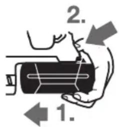
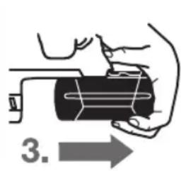
(1.)auiuJgSJIooaiIggiSjllbau (2.)18UiaJgjjLc
.3. ()
J1 pSjll uawlg 18 Jg juuS1 - Jol Ssw aJlI
psjll jw ufo
Jauuauuuu uuuuauuuuuuuuuuuuuuuuuuuuuuuuuuuuuuuuuuuuuuuuuuuuuuuuuuuuuuuuuuuuuuuuuuuuuuuuuuuuuuuuuuuuuuuuuuuuuuuuuuuuuuuuuuuuuuuuuuuuuuuuuuuuuuuuuuuuuuuuuuuuuuuuuuuuuuuuuuuuuuuuuuuuuuuuuuuuuuuuuuuuuUU
#
16 150X1 1200 all go bao aui jueSUI ci xc Jusai
(Bgglgj)
16 150 jai aai jyogai j li kai .gai gai joc go u Jn gwi
16 1021 uaaaI aIawI aaiia IaBg JJI 1021 I gsg acwI ylac aJol ai Su
aegg jgsj 16 aolx 16 oJy 16 oJy
pLal aclwU Jlac
UljjIg annll jc Ulogla
EN60745-2-6JUALLaaiuuaaLgagglalg 1sgiu:OJcAuljI (Aegi)gsuoglu Uo o giuu.(Aegi) Jus90 uu bfo .Jus3=K oglaill.(Aegi) Jusu 101
!aw a@lg sjjl
aL bIgaiI gao)ah jIjimai I aoi EN 60745-2-6 Cua K UglUg (uui
aIwJU 1uUgJU 2U/01,5=K.2U/014,5=a
1.2/0 1,5=K,²/09,5=ah:
2l/p 1,5 = K²/ρ 2,5 >ah: ∫dxdld
2U/ρ 1,5=K,²U/ρ 2,5>ah:UgU|
11 Sg EN60745 Jao 8o wu g wu loa Jau Jau
- 125 s u n l l uuul uuuu uuuu uauu uauu uauu uauu uauu uauu uauu uauu uauu uauu uauu uauu uauu uauu uauu uauu uauu uauu uauu uauu uauu uauu uauu uauu uauu uauu uauu uauu uauu uauu uauu uauu uauu uauuu uauuu uauuu uauuu uauuu uauuu uauuu uauuu uauuu uauuu uauuu uauuu uauuu uauuu uauuu uauuu uauuu uauuu uauuu uauuu uauuu uauuu uauuu uauuu uauuu uauuu uauuu uauuu uauuu uauuu uauuu uauuu uauuu uauuu
JU JU UUUU UUUUUUUUUUUUUUUUUUUUUUUUUUUUUUUUUUUUUUUUUUUUUUUUUUUUUUUUUUUUUUUUUUUUUUUUUUUUUUUUUUUUUUUUUUUUUUUUUUUUUUUUUUUUUUUUUUUUUUUUUUUUUUUUUUUUUUUUUUUUUUUUUUUUUUUUUUUUUUUUUUUUUUUUUUUuuuuuuuuuuuuuuuuuuuuuuuuuuuuuuuuuuuuuuuuuuuuuuuuuuuuuuuuuuuuuuuuuuuuuuuuuuuuuuuuuuuuuuuuuuuuuuuuuuuuuuuuuuuuuuuuuuuuuuuuuuuuuuuuuuuuuuuuuuuuuuuuuuuuuuuuuuuuuuuuuuuuuuuuuuuuuuuuuuuuuuuuuuuuuuuuuuuuuuuu uu
Joull Uyoo uubug uuul aig
uJU
(A oJgJJI gJ) pSjJI j
Ug Ug Ug Ug Ug Ug Ug Ug
gjall gjgl sall gaiig .jlllg jllg
Jglll jI JIJI/1JgJgJgJgJgJg
.
0jgaaJl:jj
auiuJgSJI oaiI pgiwJ JIOgWgauI IjJgJ iuiu
aababall gogll aao 9 0gagall
(GBH 36 VF-LI Plus)
(SDS-plus (GBH 36 VF-LI Plus JJ J J J J J J J J
SDS-plus oJJI Jol3
JzJI JQ aLgJI UaC 4
Jləg! auuu 5
(GBH 36VF-LIPlus)UJU JJI JJI JJI
jlljimai 7
Ugololglgagla 8
(gjoojaiabaw)5gdyjao 9
labzgljwulgiao 10
*aJ11
jll/ijgjj 12
jgJ/(jbll lao 13
JssJg 14
sucj.0sag aabbi gboaI ssc laIgla
a liu lai jui jil oJg bll gjbl
JUSSWgJUSSWJL
logu cdj- jclj. taalll o m u. g
Jaiol 1aill Jaiil
Jg Jg Jg Jg Jg Jg Jg
aolsswglpsjllslicg
p5joo gajll aaiwglaloo jua
jll jwJgajl bao sIjoll wai
gJUgWjBpa, gaiJIgJnLqaiuW
jUJSLJIUUuEgUaAsal uWlOe
jJJI JUo jEg zo lai
U LxLgSjSjalpsswJ .
UgJg
a2 1501 pssal lla! lcbela
Jlglg gallgagg (gJll
aJssJUjEJI JooIggl UJgUgJluuJlg
Lagssy jnnnolJUugogg gaj gll J
ydoJn jaijSJI OJI JI JAA 5gJ.
auiyjlllalwgl aoln mnn
elawil pdoaiwl jglll lmmn bai 2 4
jssi i. clll aaaaiyjyklkll oll
g aall ayljyklkll oall abwlg ylaig lq 1
. gkslll lal
laeauo uI ailyjyklkll oall pao 4
g lgluyuayuoyuoi yll aayjyklkll oall .clll
. gauu yuoyuoyuoyuau yllably
uuysyglg /g uusyyuauyauyauyauyauyauyauyauyauyauyauyauyauyauyauyauyauyauyauyauyauyauyauyauyauyauyauyauyauyauyauyauyauyauyauyauyauyauyauyauyauyauyauyauyauyauyauyauyauyauyau y
aBwgljLlIg alnlo aIg lbo
Jl
auiuJ 1 sss aolc a uo
aaggljblg jlllglalgl 11. aalglg 11. aalglg 11. aalglg 11. aalglg 11. aalglg 11. aalglg 11. aalglg 11. aalglg 11. aalglg 11. aalglg 11. aalglg 11. aalglg 11. aalglg 11.aalglg 11.aalglg 11.aalglg 11.aalglg 11.aalglg 11.aalglg 11.aalglg 11.aalglg 11.aalglg 11.aalglg 11.aalglg 11.aalglg 11.aalglg 11.aalglg 11.aal
JshuI Jka Jlo
a
4bIag jloj g. ausgllgglg i jgi 1g jglg lglg g g g g Jksw ayuysd .Jyw yuayu yuoye 0jy 0jy
aa 9. aui jgJl oai Josu wloic s
yJyJxJU 10
JgA Jn Jl gI y Jy Jy AaJ 100000000000000000000000000000000000000000000000000000000000000000000000000
1j0j0
4Lc w
420auiHJ
4uU5s
<gi aJUgJJ o
JLaaWU a
auiJqSJI oss
0s i s 152 g a o y u y alol as s jgj
aIb0,glgwsjgoXgocu glgws gac
.du
(Vario-Lock = p1g jS Jaa) p1g cuagj
calao 36 JJ wj jolgloaw Jlcu jy g uji J .Sis Gg Ss
Jg Cog j 13 gj/ajpabui JSL
ogj"du gjEgj) d yJJg"(Vario-Lock)" pJ U S .260 daa, "JL Egi Jaii
pJyolgsuogjI JJJgA. aio .sia jy s
pJyCueoog j 13 gj/ajpabui JSL
Jao oos jJJjJJJJJJJJJg
gbsdss Jus Jus Jus Jus
.10
jla lgl 8 ju jui sLs:Jswl
Jla Js LgU 8 aas
.
g g jg w g
puii iuiuui uaiy auiuua (gij pia) 15
.
jJ5 uqolg juogjogai
jg jg bag j g jj1g jg
ssolawl jilgloa sis
10 gg bgs jj j 1s g
JwJw
jglg jglg jgs
a 1j1 j0ai j s j s uaiu
.duu uugolgulwusugjgluglpuu
10 1og g e b aL g Jj uS wgla
Sis Lj Ss
Cmu/duo slsui buiogai
jg jw gj lJ dJdJ/ucw ylgua
ds da dsi Jg
L 10 g b
jgaiol oqo jgai! jS. gai aai jy jg
j1 j u. y. 2u. 2u. 2u. 2u. 2u. 2u. 2u. 2u. 2u. 2u. 2u. 2u. 2u. 2u. 2u. 2u. 2u. 2u. 2u. 2u. 2u. 2u. 2u. 2u. 2u. 2
JjJlglio
1jglj 13 gg g aai
Jg((SJSg)SSJJ
(Kgagd gghgj)olss (59j1 jj! jn
a 100
oJUjLjJjJjJJJoo
ds jy 28 gglgul
- 山 山 山 山 山 山 山 山 山
(1alao)GDE 16 Plus L JLe g sJ S
Lw yIg 1jg gJgJg
jg jg uaiu g uj cwsui
Saa (sJao sJao ly g sJJg jy ccl wJoo
Sjj jJdAsLg gsslaaw
sigu siu lu
Iggljg g sio gogao (lojg
gij jogaa.iiuuij j ubw wj cjs g
1go,log)gogSgJgSgJgLo
1jIb0g. jigu 0Jy (ugjI cahao
siwLgCwJglJdsIgLoJjLgauusio
.
4.2
.0s o1oo1 (jS a2b9) 0slo
- jgj g wli
L
-1sIg0d g9j1la.
- jil@ aJ s L ia
.0s oLwP2
LabJggsjusooJJg gjjgdd
aagj g jg j
山
.igw Jlauo jilw a sui gj o jucg jg
(GDE16Plusjjjjg
.
cuiio jj gao jia d2b g 5u yu o si ool
.
jIbJgJzooLwSsJdSsJgJgJSoS
(SDS-plus) (GBH 36 VF-LI Plus)
(jgag y gggj) j! g jds jg oog
SsL sJSDS-plus g y Jd j1 j:
pJg SDS-plus g y Jl! Jy Jy SsL pJg
(gj pJ) sJg g GsSg Ls Psin a Jg
.
1 12uogj Uglogil pblc -
Jgss JIgolgl 29 o sis Jgdo aal -
o Jo JIgai ly I jyj1 .sJgSj psoo Jgws
dio JIgui dS i Ss L 28 gla gil
Soo J 29 o sis Jgao daa .sJg Jn Jlal
uagc jy ssoo jgb1 28 gog yds
gog jgb1 uJnLiig1 ly gl do Jgajgdi
. gwi
1j j 1u u w g n jg j jj u u u
JSoI,swOswjUwUdawuUgUgUgUgUgUgUgUgUgUgUgUgUgUgUgUgUgUgUgUgUgUgUgUgUgUgUgUgUgUgUgUgUgUgUgUgUgUgUgUgUgUgUgUgUgUgUgUgUgUgU
JW u gj Jg Lpdu d w jw 100 (D ggi a gw egj)
a 6 g w u g ju pai w o s iS J aal a
dw g yjg j kao cui jau jj, uuy
dw lg SDS-plus ay joo 2 g w u g ju Lg pai
. uuy gl ay 1 g w u g ju Lg slogil pai
.
yagaiu 1g gjg jg (E yagai ygwhgj)
sIaJwSdJyabJyJgdsOlaaw 26 JawIaIeio JaaW JgJLgolpbiawjlOlaawI Jssio JaoJaaW SjLJw dU ggsJq
| 28 | 28 | mm | - √ √ √ √ √ √ √ √ √ √ √ √ √ √ √ √ √ √ √ √ √ √ √ √ √ √ √ √ √ √ √ √ √ √ √ √ √ √ √ √ √ √ √ √ √ √ √ √ √ √ ∇ √ √ √ √ √ √ √ √ √ √ √ √ √ √ √ √ √ √ √ √ √ √ √ √ √ √ √ √ √ √ √ √ √ √ √ √ √ √ √ √ √ √ √ √ √ √ √ √ √ ∶ √ √ √ √ √ √ √ √ √ √ √ √ √ √ √ √ √ √ √ √ √ √ √ √ √ √ √ √ √ √ √ √ √ √ √ √ √ √ √ √ √ √ √ √ √ √ √ √ √ ∙ √ √ √ √ √ √ √ √ √ √ √ √ √ √ √ √ √ √ √ √ √ √ √ √ √ √ √ √ √ √ √ √ √ √ √ √ √ √ √ √ √ √ √ √ √ √ √ √ √ ∗ √ √ √ √ √ √ √ √ √ √ √ √ √ √ √ √ √ √ √ √ √ √ √ √ √ √ √ √ √ √ √ √ √ √ √ √ √ √ √ √ √ √ √ √ √ √ √ √ √ ∘ √ √ √ √ √ √ √ √ √ √ √ √ √ √ √ √ √ √ √ √ √ √ √ √ √ √ √ √ √ √ √ √ √ √ √ √ √ √ √ √ √ √ √ √ √ √ √ √ √ ∞ √ √ √ √ √ √ √ √ √ √ √ √ √ √ √ √ √ √ √ √ √ √ √ √ √ √ √ √ √ √ √ √ √ √ √ √ √ √ √ √ √ √ √ √ √ √ √ √ √ ∫ ∫ ∫ ∫ ∫ ∫ ∫ ∫ ∫ ∫ ∫ ∫ ∫ ∫ ∫ ∫ ∫ ∫ ∫ ∫ ∫ ∫ ∫ ∫ ∫ ∫ ∫ ∫ ∫ ∫ ∫ ∫ ∫ ∫ ∫ ∫ ∫ ∫ ∫ ∫ ∫ ∫ ∫ ∫ ∫ ∫ ∫ ∫ ∫ ∫ ∅ ∅ ∅ ∅ ∅ ∅ ∅ ∅ ∅ ∅ ∅ ∅ ∅ ∅ ∅ ∅ ∅ ∅ ∅ ∅ ∅ ∅ ∅ ∅ ∅ ∅ ∅ ∅ ∅ ∅ ∅ ∅ ∅ ∅ ∅ ∅ ∅ ∅ ∅ ∅ ∅ ∅ ∅ ∅ ∅ ∅ ∅ ∅ ∅ ∅ ∆ ∅ ∅ ∅ ∅ ∅ ∅ ∅ ∅ ∅ ∅ ∅ ∅ ∅ ∅ ∅ ∅ ∅ ∅ ∅ ∅ ∅ ∅ ∅ ∅ ∅ ∅ ∅ ∅ ∅ ∅ ∅ ∅ ∅ ∅ ∅ ∅ ∅ ∅ ∅ ∅ ∅ ∅ ∅ ∅ ∅ ∅ ∅ ∅ ∅ ∈ ∅ ∅ ∅ ∅ ∅ ∅ ∅ ∅ ∅ ∅ ∅ ∅ ∅ ∅ ∅ ∅ ∅ ∅ ∅ ∅ ∅ ∅ ∅ ∅ ∅ ∅ ∅ ∅ ∅ ∅ ∅ ∅ ∅ ∅ ∅ ∅ ∅ ∅ ∅ ∅ ∅ ∅ ∅ ∅ ∅ ∅ ∅ ∅ ∅ ∲ ∅ ∅ ∅ ∅ ∅ ∅ ∅ ∅ ∅ ∅ ∅ ∅ ∅ ∅ ∅ ∅ ∅ ∅ ∅ ∅ ∅ ∅ ∅ ∅ ∅ ∅ ∅ ∅ ∅ ∅ ∅ ∅ ∅ ∅ ∅ ∅ ∅ ∅ ∅ ∅ ∅ ∅ ∅ ∅ ∅ ∅ ∅ ∅ ∅ ∼ ∅ ∅ ∅ ∅ ∅ ∅ ∅ ∅ ∅ ∅ ∅ ∅ ∅ ∅ ∅ ∅ ∅ ∅ ∅ ∅ ∅ ∅ ∅ ∅ ∅ ∅ ∅ ∅ ∅ ∅ ∅ ∅ ∅ ∅ ∅ ∅ ∅ ∅ ∅ ∅ ∅ ∅ ∅ ∅ ∅ ∅ ∅ ∅ ∅ ∬ ∅ ∅ ∅ ∅ ∅ ∅ ∅ ∅ ∅ ∅ ∅ ∅ ∅ ∅ ∅ ∅ ∅ ∅ ∅ ∅ ∅ ∅ ∅ ∅ ∅ ∅ ∅ ∅ ∅ ∅ ∅ ∅ ∅ ∅ ∅ ∅ ∅ ∅ ∅ ∅ ∅ ∅ ∅ ∅ ∅ ∅ ∅ ∅ ∅ ∍ ∅ ∅ ∅ ∅ ∅ ∅ ∅ ∅ ∅ ∅ ∅ ∅ ∅ ∅ ∅ ∅ ∅ ∅ ∅ ∅ ∅ ∅ ∅ ∅ ∅ ∅ ∅ ∅ ∅ ∅ ∅ ∅ ∅ ∅ ∅ ∅ ∅ ∅ ∅ ∅ ∅ ∅ ∅ ∅ ∅ ∅ ∅ ∅ ∅ ∱ ∅ ∅ ∅ ∅ ∅ ∅ ∅ ∅ ∅ ∅ ∅ ∅ ∅ ∅ ∅ ∅ ∅ ∅ ∅ ∅ ∅ ∅ ∅ ∅ ∅ ∅ ∅ ∅ ∅ ∅ ∅ ∅ ∅ ∅ ∅ ∅ ∅ ∅ ∅ ∅ ∅ ∅ ∅ ∅ ∅ ∅ ∅ ∅ ∅ ∽ ∅ ∅ ∅ ∅ ∅ ∅ ∅ ∅ ∅ ∅ ∅ ∅ ∅ ∅ ∅ ∅ ∅ ∅ ∅ ∅ ∅ ∅ ∅ ∅ ∅ ∅ ∅ ∅ ∅ ∅ ∅ ∅ ∅ ∅ ∅ ∅ ∅ ∅ ∅ ∅ ∅ ∅ ∅ ∅ ∅ ∅ ∅ ∅ ∅ ∫ ∅ ∅ ∅ ∅ ∅ ∅ ∅ ∅ ∅ ∅ ∅ ∅ ∅ ∅ ∅ ∅ ∅ ∅ ∅ ∅ ∅ ∅ ∅ ∅ ∅ ∅ ∅ ∅ ∅ ∅ ∅ ∅ ∅ ∅ ∅ ∅ ∅ ∅ ∅ ∅ ∅ ∅ ∅ ∅ ∅ ∅ ∅ ∅ ∈ ∈ ∅ ∅ ∅ ∅ ∅ ∅ ∅ ∅ ∅ ∅ ∅ ∅ ∅ ∅ ∅ ∅ ∅ ∅ ∅ ∅ ∅ ∅ ∅ ∅ ∅ ∅ ∅ ∅ ∅ ∅ ∅ ∅ ∅ ∅ ∅ ∅ ∅ ∅ ∅ ∅ ∅ ∅ ∅ ∅ ∅ ∅ ∅ ∅ ∈ ∧ ∅ ∅ ∅ ∅ ∅ ∅ ∅ ∅ ∅ ∅ ∅ ∅ ∅ ∅ ∅ ∅ ∅ ∅ ∅ ∅ ∅ ∅ ∅ ∅ ∅ ∅ ∅ ∅ ∅ ∅ ∅ ∅ ∅ ∅ ∅ ∅ ∅ ∅ ∅ ∅ ∅ ∅ ∅ ∅ ∅ ∅ ∅ ∅ ∅ ∇ ∅ ∅ ∅ ∅ ∅ ∅ ∅ ∅ ∅ ∅ ∅ ∅ ∅ ∅ ∅ ∅ ∅ ∅ ∅ ∅ ∅ ∅ ∅ ∅ ∅ ∅ ∅ ∅ ∅ ∅ ∅ ∅ ∅ ∅ ∅ ∅ ∅ ∅ ∅ ∅ ∅ ∅ ∅ ∅ ∅ ∅ ∅ ∅ ∅ ∿ ∅ ∅ ∅ ∅ ∅ ∅ ∅ ∅ ∅ ∅ ∅ ∅ ∅ ∅ ∅ ∅ ∅ ∅ ∅ ∅ ∅ ∅ ∅ ∅ ∅ ∅ ∅ ∅ ∅ ∅ ∅ ∅ ∅ ∅ ∅ ∅ ∅ ∅ ∅ ∅ ∅ ∅ ∅ ∅ ∅ ∅ ∅ ∅ ∅ ∪ ∅ ∅ ∅ ∅ ∅ ∅ ∅ ∅ ∅ ∅ ∅ ∅ ∅ ∅ ∅ ∅ ∅ ∅ ∅ ∅ ∅ ∅ ∅ ∅ ∅ ∅ ∅ ∅ ∅ ∅ ∅ ∅ ∅ ∅ ∅ ∅ ∅ ∅ ∅ ∅ ∅ ∅ ∅ ∅ ∅ ∅ ∅ ∅ ∅ ∴ (∂ ⊿ 0 . 0 0 0 0 0 0 0 0 0 0 0 0 0 0 0 0 0 0 0 0 0 0 0 0 0 0 0 0 0 0 0 0 0 0 0 0 0 0 0 0 0 0 0 0 0 0 0 0 0 0 1) | ||||
| 4,1/4,61) | 4,0/4,51) | kg | EPTA-Procedure 01:2014 gjnjnjnjnjnjnjnjnjnjnjnjnjnjnjnjnjnjnjnjnjnjnjnjnjnjnjnjnjnjnjnjnjnjnjnjnjnjnjnjnjnjnjnjnjnjnjnjnjnjnjnjnjnjnjnjnjnjnjnjnjnjnjnjnjnjnjnjnjnjnjnjnjnjnjnjnjnjnjnjnjnjnjnjnjnjnjnjnjnjnjnjnjnjnjnjnjnjnjnjnjNJJNJJNJJNJJNJJNJJNJJNJJNJJNJJNJJNJJNJJNJJNJJNJJNJJNJJNJJNJJNJJNJJNJJNJJNJJNJJNJJNJJNJJNJJNJJNJJNJJNJJNJJNJJNJJNJJNJJNJJNJJNJJNJJNJJNJJNJJNJJNJJNJJNJJNJNJJNJJNJJNJJNJJNJJNJJNJJNJJNJJNJJNJJNJJNJJNJJNJJNJJNJJNJJNJJNJJNJJNJJNJJNJJNJJNJJNJJNJJNJJNJJNJJNJJNJJNJJNJJNJJNJJNJJNJJNJJNJJNJJNJJNJJNJJNJJNJJNJJNJ JNJJNJJNJJNJJNJJNJJNJJNJJNJJNJJNJJNJJNJJNJJNJJNJJNJJNJJNJJNJJNJJNJJNJJNJJNJJNJJNJJNJJNJJNJJNJJNJJNJJNJJNJJNJJNJJNJJNJJNJJNJJNJJNJJNJJNJJNJJNJJNJJNJJNJJPJJPJPJPJPJPJPJPJPJPJPJPJPJPJPJPJPJPJPJPJPJPJPJPJPJPJPJPJPJPJPJPJPJPJPJPJPJPJPJPJPJPJPJPJPJPJPJPJPJPJPJPJPJPJPJPJPJPJPJPJPJPJPJPJPJPJPJPJPJPJPJPJPJPJPJPJPJPJPJPJPJPJPJPJPJPJPJPJPJPJPJPJPJPJPJPJPJPJPJPJP JPJPJPJPJPJPJPJPJPJPJPJPJPJPJPJPJPJPJPJPJPJPJPJPJPJPJPJPJPJPJPJPJPJPJPJPJPJPJPJPJPJPJPJPJPJPJPJPJPJPJPJPJPJPJPJPJPJPJPJPJPJPJPJPJPJPJPJPJPJPJPJPJPJPJPJPJPJPJPJPJPJPJPJPJPJPJPJPJPJPJPJPJPJPJPJPJPJPJPJPjpJPjpjpjpjpjpjpjpjpjpjpjpjpjpjpjpjpjpjpjpjpjpjpjpjpjpjpjpjpjpjpjpjpjpjpjpjpjpjpjpjpjpjpjpjpjpjpjpjpjpjpjpjpjpjpjpjpjpjpjpjpjpjpjpjpjpjpjpjpjpjpjpjpjpjpjpjpjpjpjpjpjpjpjpjpjpjpjpjpjpjpjpjpjpjpjpjpjpjpjpjp JPJPJPJPJPJPJPJPJPJPJPJPJPJPJPJPJPJPJPJPJPJPJPJPJPJPJPJPJPJPJPJPJPJPJPJPJPJPJPJPJPJPJPJPJPJPJPJPJPJPJPJPJPJPJPJPJPJPJPJPJPJPJPJPJPJPJPJPJPJPJPJPJPJPJPJPJPJPJPJPJPJPJPJPJPJPJPJPJPJPJPJPJPJPJPJPJPJPJP JP JP JP JP JP JP JP JP JP JP JP JP JP JP JP JP JP JP JP JP JP JP JP JP JP JP JP JP JP JP JP JP JP JP JP JP JP JP JP JP JP JP JP JP JP JP JP JP JP JP JP JP JP JP JP JP JP JP JP JP JP JP JP JP JP JP JP JP JP JP JP JP JP JP JP JP JP JP JP JP JP JP JP JP JP JP JP JP JP JP JP JP JP JP JP JP JP JP JP JP J J J J J J J J J J J J J J J J J J J J J J J J J J J J J J J J J J J J J J J J J J J J J J J J J J J J J J J J J J J J J J J J J J J J J J J J J J J J J J J J J J J J J J J J J J J J J J J J J J J JJ J J J J J J J J J J J J J J J J J J J J J J J J J J J J J J J J J J J J J J J J J J J J J J J J J J J J J J J J J J J J J J J J J J J J J J J J J J J J J J J J J J J J J J J J J J J J J J J J J J J | ||||
wai
(AggaaggEgJ)SjLjSjjogai
aao 1jdo ly g lbo sljjl jI oJgoad
s0laawl gJluIgJUaIalso a bgo
jg-ogjjl slw jjL wsl oJi JI L qii
.1iowio gbiobio low jIjli (Li-lon)
JU JU JU JU JU JU JU JU JU JU JU JU JU JU JU JU JU JU JU JU JU JU JU JU JU JU JU JU JU JU JU
jIw g am lgio (Li-1) (gjog yu (sL sJU g. gaw aws jac gbl dSj ngy, gai .siwu (sjlu u w Jjw
Ll 111 (Li-1) g-gg w 111 111 111 111 111 111 111 111 111 111 111 111 111 111 111 111 111 111 1
jgl jy jI logil wgolj u 1u 1. gog g g
(μu)
gilo lalag aLdawu o algo g sI J1 11 sJU do s s uulgai jui j sJi uoi i ngj Jus JsJy d as jioj .siu 18 Jg0 sis slj J jg SbWgi yu bduo qn Jy Jy
wla j|g|a b gjo c1b1
EN60745-2-6 gw
gj jU ggs JJw A wK gws baw .90dB(A) gws Jw gws:U Cws U Jds 120 (CbspOsc) Ibs w. .101 dB(A) gws U Jds Bw .K=3dB
!s s o slawl jai l wg j
g (a a w l j g) an wj J 1J EN60745-2-6 igw o dawl s jsiwi liy K U
[ K = 1.5 \, \text{m/s}^2, a_h = 14.5 \, \text{m/s}^2 : \dot{u} \ddot{u}, \quad \text{S} \cup \dot{u} \leq \dot{u} \leq \dot{s}_a ]
[ K = 1.5 \, \text{m/s}^2, a_h = 9.5 \, \text{m/s}^2: \text{LSLS} ]
[ K = 1.5 \, \text{m/s}^2 \cdot a_h < 2.5 \, \text{m/s}^2 \quad : jLg \quad \text{J} \leqslant \text{S} \leqslant \text{L} \leqslant gw ]
[ \mathrm{K} = 1.5\mathrm{m} / \mathrm{s}^{2}, a_{n} < 2.5\mathrm{m} / \mathrm{s}^{2} : L_{\text{总}} ]
w g jL JgJgJgJgJgJgJgJgJgJgJgJgJgJgJgJgJgJgJgJgJgJgJgJgJgJgJgJgJgJgJgJgJgJgJgJgJgJgJgJgJgJgJgJgJgJgJgJgJgJgJg
jI wui jwabw ggo jggl juiaao .gai
CwI CwLIO jj J
JjI JI JI JI JI JI JI JI JI JI JI JI JI JI JI JI JI JI JI JI JI JI JI JI JI JI JI JI JI JI JI JI JI JI JI JI JI JI JI JI JI JI JI JI JI JI JI JI JI JI JI
Jg jolj yj wj jw g qd s g jy C
jw g oLs dsi | g cwi wgola olsws as
jbi jds gaii di jy bjo j j klg w
1j wj jl wu jw zbw sglqdoa uo .cgs
.65 p 2000 g a jls 10g j
jI g Iw l wj jy Jy cclao ioi Iol
JSL OIS W J ds 5jgcblaa 1y I jgi S
9 g jy jy wg w Uio ng jy jy jy
W JLOJW g Lw nnw
S = S J_0
*15pU 11
g g a o s iS puii jg o sii S slj dss 12
g w yogj Ug Slogj pbld w 1
(GBH 36 VF-LI Plus)
SDS-plus a jgoo g uu uogu 2
(GBH 36 VF-LI Plus)
SDS-plus joo 3
jg jg ju ju uagao 4
Jg(w)Jg5
yjg jI gai daw sS Jagda 6
(GBH 36 VF-LI Plus)
wJg uJU SUs 7
uuaa uuaui 8
(jsc)c(gj)duw9
Jog ggbu 10
giulosuo
U
jolaw3611J060..361
cmu bji gjuiS●
jua jagg
sβ/sβωj
Jw uagjU lla oju dW
UjUgV=3636
600 600