
Airboss DN 200105 - Compressor STANLEY - Free user manual and instructions
Find the device manual for free Airboss DN 200105 STANLEY in PDF.
| Product type | Portable air compressor |
| Brand | Stanley |
| Model | Airboss DN 200105 |
| Power supply | 230 V ~ 50 Hz, 16 A fuse |
| Maximum tank pressure | 10 bars (145 PSI) |
| Pressure regulation | Yes, via rotary knob |
| Tank pressure gauge | Yes, graduated in PSI and BAR |
| Regulated pressure gauge | Yes |
| Safety valve | Yes, set to 10 bars (non-adjustable) |
| Drain valve (purge) | Yes, ball valve |
| Quick coupling | Yes, for air hose |
| Switch | On/Off with indicator light |
| Intermittent operation | Duty cycle ≤ 15% (integrated thermal protection) |
| Thermal protection | Yes, automatic shutdown in case of overheating |
| Transport | Handle and removable shoulder strap |
| Tool attachment | Velcro strap for pneumatic tool or hose |
| Accessory compartment | Yes, integrated |
| Cleaning | Damp cloth with mild soap; do not use solvents |
| Condensation drain | Daily, via drain valve in low position |
| Spare parts and repairability | Via authorized service center; use original parts |
| Intended use | Inflation, pneumatic tools, painting (non-breathable air) |
| Safety precautions | Do not direct jet at people; wear goggles; keep children away |
Frequently Asked Questions - Airboss DN 200105 STANLEY
User questions about Airboss DN 200105 STANLEY
0 question about this device. Answer the ones you know or ask your own.
Ask a new question about this device
Download the instructions for your Compressor in PDF format for free! Find your manual Airboss DN 200105 - STANLEY and take your electronic device back in hand. On this page are published all the documents necessary for the use of your device. Airboss DN 200105 by STANLEY.
USER MANUAL Airboss DN 200105 STANLEY
Manufactured under license by:
Nu Air Compressors And Tools S.p.A. - via Einaudi 6, 10070 Robassomero (TO) Italy
Stanley® is a registered trademark of The Stanley Works or its affiliates and is used under license.
Conservare Anything manuale d'istruzioni per poterlo consultare in futuro
GB Preserve this handbook for future reference
FR Conserver le present manuel pour pouvoir le consulter ulterieurement
DE These Bedienungsanleitung fur späteres Nachschlagen sorgfältig aufbewahren
ES Conservar este manual de instrucciones para poder consultarlo en el futuro
Guardar este manual de instruções para o poder consulitar no futuro
NL Bewaar deze handleiding voor toekomstige raadpleging
Opbevar denne brugsanvising saledes, at det altid er muligt at indhente oplysninger pa et senere tidspunkt
SE Forvara denna bruksanvising for framtida konsultation
Fl Sailyta ohjekirja voidaksesi etsi siita tarvittaessa ohjeita
GR uAaTe To TApov ExyEipidio OoyniW yia eAiovTik xpnon
PL Przechowywać niniejszy podręcznik instrukcji obstrugi tak, aby są za boły korzystać z niedgo w przyszlosci
HR Sačuvajte ovaj prirucnik s uputama da biste ga mogli konzultirati u budućnosti
SI Skrbno shranite ta prirocnik
HU Orizze meg a kezikonyvet a jovoben valo tanulmányozáshoz
Ulozte tut o priu c u spokny pro pouziti na vhdnem miste, abyste ji mohli kdykoli pouzit
SK Uschovajte tuto priručku sPokynmi na obsluhu pristroja tak,aby ste mohli do nej kedykolvek nahliadnú
RcOxpaHnTe daHHoe pyKOBoCTBO TteHHe BCero nepnoJa 3KcnNyataun KOMnpeccca
NO Du ma oppbevarne donne bruksanvisingen sik at du kan sla opp i den ved senere behov
IR Bu kullanim kilavuzunu gelecekte danismak icin muhafaza ediniz
Ro Paastra manualul de instrueti npi entru a-l putea citi si pe viitor
BG 3ana3eTOBA pkoBOcTBO NO eKcnloaatauYra, 3a da MOKeTe da ro n3non3BaTe n B6bdeue
RS Sacuvajte ovaj priučnik s uputstvima da bi mogli da ga konsultujete i buducnosti
LT Saglabat instrukciju rokasgramatu, lai varetu izmantot nepiecieamibas gadijumā
EE Hoidke kaesolevat kasutusjuhendit alles, et saaksite seda tulevikus kasutada
LV Issaogoti sia instrukcju knygute tam, kad ateityje galétumete jope pasikonsultuoti
LEGENDA SEGNALETICA DI SICUREZZA SUI PRODOTI
GB KEY TO PRODUCT SAFETY SIGNS
FR LEGENDE DES PICTOGRAMMES DE SECURITE FIGURANT SUR LES PRODUITS
DE ERKLÄRUNG DER SICHERHEITSKENNZECHNUNG AN DEN PRODUKTHEN
ES INSCRIPCION DE LA SENALIZACION DE SEGURIDAD COLOCADA EN LOS PRODUCTOS
LEGENDA DA SINALETICA DE SEGURANCA NOS PRODutos
NL VERKLARING WAARSCHUWINGSSYMBOLEN OP PRODUCTEN
DK SIGNATURFORKLARING TIL PRODUKTERNES SIKKERHEDSSKILTNING
SE FÖRKLARING TILL SÄKERHETSSYMBOLER PAPRODUKTERNA
FUOTTEITA KOSKEVAT TURVAMERKIT
GR YNOMNHMA ZHMATON AZΦAIAEIA ΣTA IPOIONTA
PL LEGENDA ZNAKOW OSTRZEGAWCZYCH NA WYROBACH
HR ZNAKOVI ZA UPOZORENJE NA PROIZVODIMA
OPOZORILNI ZNAKI NA PROIZVODIH
HU A TERMÉKEKEN TALÁLHATO BIZTONSAGI JELZÉSEK LISTAJA
CZ BEZPECNOSTNI ZNAÇENI NA VYROBCICH
LEGENDA: BEZPECNOSTNE OZNACENIA NA VYROBKOCH
RU YCNOBHBIE INPEDYNPENEINTBHBE 3HAKINIO B6E30NACHOCTI PABOTbIC N3DEINRM
NO SIKKERHETSTEGNFORKLARING PÄ PRODUKTENE
TR URUNLER HAKKINDA GUVENLIK TALIMATLARI LEJANDI
RO LEGENDA INDICATOARELOR DE SECURITATE APLICATE PE PRODUSE
BG JIeEHJHA 3HAJIITE 3A BE3OJNACHOCT BbPxy N3DEJINRA
UPOZORAVAJUCE NAZNAKE O BEZBEDNOSTI PROIZVODA
LT SUTARTINIAI JSPÉJAMIEJI ZENKLAI DEL DARBO SAUGUMO SU GAMINIAIS
EE OHUTUSNOUDED
LV PRODUKTU DROSBAS NORADIJUMA ZIMJU SARAKSTS

IT Leggere attentamente il manuale d'istruzioni prima dell'uso
GB Before use, read the handbook carefully
FR Lire attentivement le Manuel Opérateur avant toute utilisation
DE Vor Inbetriebnahme Gebrauchsanleitung aufmerksam lesen
ES Leer atentamente el manual de instrucciones antes de usar el equipo
PT Ler com atenção o manual de instruções antes do uso
NL Lees voor gebruik aandachtig de handleiding door
DK Laes omhyggeligt instruktsmanualen for brug
SE Lás bra克斯anvisingen noggrant fore användning
FI Lue käytöopas huolelliseti ennen käyttoa
GR AiaBaeTe TPOeKTIKA To EYExeiDIO OOnyiwv Tpv aTo Txprn
PL Przed uzyciem nalezy dokladnie zapoznać sie z instrukcjami obstugi
HR Prijeputrebe pazljivo procitajte upute za upotrebo
SI Pred uporabo, pazljivo preberite navodila za uporabo
HU Hasznalat elott figyelmesen olvassa el a kezikonyvet
CZ Prid zahajenim prace si pozorné preclte pro pirucku pro pouziti.
SKPred pouzivanmVyrobku si pozorne precitajte navod na jeho pouzitie
RU NpeaTe TM, KaN pNCTyNTb K pa6Ote, BHMMaTeIbHO npOHTaTHe HCHtpKuHIO NO 3KcNIIyatauH
NO Les noye bruksanvisningen for bruk
TR Kullanimdan once kullanim kilavuzunu dikkatice okuyunuz
RO Cititi cu atenie manualul de instructiani inainte deutilizare!
BG BHHMATEHNO npoHTe pkoBDCTBTO no ekcnnoataa npeynyntpeba
RS Pre upotrebe pažljivo pročitajte priručnik s uputstvima
LT Pries imdamiesi darbo atidziai perskaitykite naudojimo vadoveli
EE Enne kasutamist lugege kasutamisjuhend tahelepanelikult labi
LV Uzmanigi izlasiet izmantoşanas instrukciju pirms produkta lietşanas

IT Pericolo di scottature
GB Warning, hot surfaces
FR Risque de brûlures
DE Verbrennungsgefahr
ES Peligro de quemaduras
PT Perigo de queimaduras
NL Gevaar voor brandwonden
DK Risiko for skoldning
SE Risk for brannskador
FI Palovammavaara
GR Kivvoc ykaumatw
PL Uwaga, grozi poparzeniem
HR Opasnost opekotina
SI Nevarnost opeklin
HU Figyelem, egeto feuletek
CZ Nebezpeci spalen!
SK Nebezpečenstvo popálenia!
RU Onachoctb oxkora
NO Fare for a brenne seg
TR Yanma tehlikesi
RO Pericol de arsuri
BG OnachocOTn3rapHm
RS Opasnost od opekotina
LT Nudegimo pavojus
EE Suttivuse oht
LV Piesargieties no ap dedzin ana

IT Attenzione corrente elettrica
GB Dangerous voltage
FR Attention: presence de courant electrique
DE Achtung, elektrische Spannung
ES Atencion, corriente electrica
PT Atença corrente electrica
NL Attentie, elektrische stroom
DK Advarsel elektrisk strøm
SE Varning - elektricitet
FI Huom. vaarallinen jannite
GR Ppooxn nAeKtpiok oEmu
PL Uwaga, niebezmieczneistwo porazenia pradem elektrycznym
HR Pažnja, elektrčni napon
SI Pozor, elektricna napetost
HU Figyelem, elektromos áram
CZ Pozor - elektrické napét!
SK Pozor - elektricky prud!
RU Puck 3neKtpueckoro HaprjKeHHa
NO Forsiktig elektrisk strom
TR Dikkat elektrik akimi
RO Atentie! Pericol electric
BG BHIMAHHe: eJektpueKm TOK
RS Pažnja elektricna struja
LT Elektros jtampos rizika
EE Ettevaust - elektrivool
LV Esiet uzmanigi - elektribas plusma
IT Pericolo avviamento automatico
GB Danger - automatic control (closed loop)
FR Risque de démarriage automatique
DE Gefahr durch automatischen Anlauf
ES Peligro de arranque automatico
PT Perigo arranque automatico
NL Gevaar voor automatisch starten
DK Fare automatisk start
SE Risk for automatisk start
FI Automaattisen kaynnistymisen vaara
GR Kivovoc autopatng Ekkivnong
PL Uwaga, niebezpieczeni stwo automatyczneo uruchomienia sie
HR Opasnost kod automastkog uklapanja
SI Nevarnost pri avtomatskem zagonu
HU Automatikus beindulas veszelye
CZ Nebezpeci - automatické spoustén!
SK Nebezpečenstvo - automatické spustenie!
RU OnaHocTb aBTOMaTHueCKOrO BKNIOueHn
NO Fare for automatisk oppstart
TR Dikkat otomatik calisma tehlikesi
RO Pericol pornire automata
BG OnachOCT OT ABOTMATHNO NyCKAHe B XoD
RS Opasnost od automatskogPokretanja
LT Automatinio sijungimo pavojus
EE Ohtlik - automaatiline käivitus
LV Uzmanibu - automatiska iedarbinasanas
HORIZONTAL RUNNING

IT II compressore delve funzionare solo ed esclusivamente in posizione orizzontale
GB The compressor must only and exclusively be operated in a horizontal position
FR Le compresseur doit fonctionner exclusivement en position horizontale
DE Der Kompressor darf ausschließlich in horizontaler Position arbeiten
ES El comprsor debe funcionar solo y exclusivamente en posicio horizontal
PT O compressoruve funcionareapanas e exclusivamente em posicao horizontal
NL De compressor mag alleen en uitsluitend in werkig gesteld worden in horizontale stand
DK Kompressoren skal altid ligge vandret ned under brugen
SE Kompressorn skatateslutande fungera i horisontalt lage
FI Kompressoria saa kayttä ainoastaan vaaka-asennossa
GR O aumieotn Cpnte va aeitoupye i ovo kai anokkiaikc opiovia b
PL Kompresor musi byc uzytkowany wylacznie w pozycj poziomej
HR Kompresor smje Jedino i iskjučivo raditi u okomitom položaju
SI Kompresor mora biti vedno v vodoravnem polozaju
HU A kompresszort kizarolag vizszintes helyzetben
CZ Kompresor smi byt pouzivan pouze a vylucne ve vodorovnpepoze
SK Kompresor smie byt' uvedeny do prevadzky vylucne vo vodorovnej polohe
RU Komnpecccop donjkeh pa60TaTb TOnbKO B rOpn3OHTaBbHOM noJIOKeHN
NO Kompressoren mä kun fungere i horisontal posisjon
TR Kompresor sadece ve sadece yatay konumda
RO Compresorul trebuie utilizat exclusiv in poziţie ortonatala
BG KomnpecopbT Tp6Ba da yHKnOHa pa cMo B XOpN3oHTaHNO NONOKeHne
RS Kompresor sme da radi samo u vertikalnom položaju
LT Kompresorius turi dirbtik horizontalioje padetye
EE Kompressorit vioib kasutada ainult horisontaalasendis
LV Darba laika kompresoram jabut horizontala pozfcja


IT Protezione obbligatoria dell'udito, della vista e delle vie respiratoriie
GB Hearing, sight and respiratory protection must be worn
FR Port obligatoire de protections auditives, oculaires et des voies respiratoires
DE Gehorschutz, Augenschutz und Atemschutz sind obligatorisch vorgeschrieben
ES Proteccion obligatoria de los oidos, de la vista y de las vias respiratorias
PT Proteção obrigatória do ouvido, da vista e das vias respiratórias
NL Verplichte bescherming van oren,ogen en luchtwegen
DK Obligatorisk beskyttele af horelse, syn og luftveje
SE Horselskydd, skyddsglasogon och andningsmask obligatoriskt
FI Käytettäva kuulosuojaimia, suojalaseja ja hengityksensuojaimia
GR YTOxpeWtiko TPOoTATEUTKO aKoN, Opaan KAI TOU AVATVEuOTIKOUaTJmuos
PL Obwiazkowo zabeprpieczyc sluch, wzrok i drogi oddechowe
HR Obavezna zaftita oocju,disnih puteva i sluha
SI Obvezna zašita oci, dihal in sulha
HU A legutak, a latas es a hallas vedelme kotelez
CZ Povinnost chrnilt sluch, oci a dychacfi cesty.
SK Povinná ochrana sluchu, zraku a dychacích ciest!
RU O63aTeJbHaa 3aunTa ywei, mua n dixaTeJbHbIX nyTei
NO Obligatorisk a ta i bruk horselsver, vernebriller og pustemaske
TR Mecburi isitme, gorme ve solunum yollari korumasi
RO Echipament de protectie obligatoriu pentru urechi, ochi si cai respiratori
BG 3aBnKTeHnCpeDCTBa3a3uHaHacnyxa,3peHMeTOuNxatENHTenTbTu
RS Obavezna zaistita sluha, vida i disnih puteva
LT Privaloma ausu, veido ir kvépavimo taku apsauga
EE Kuulmis-, nagenis- ning hingamisteede kaitse on kohustuslik
LV Obligata dzirdes, redzes un elpoanas celu aizsardziba
| F C | |||||||||||
| HP kW I gallons l/min | cfm volt | Hz A min | -1 | bar PSI kg lbs. g | |||||||
| DN 200/10/5 | 1.5 | 1.1 | 5 | 1.2 | 180 | 6.4 | 230 - 50 | 5.5 | 3400 | 10 | 145 |
1
2
3
4
H
5
6a
6b
1. PRECAUZIONI D'USO
Preserve this handbook for future reference.
1. PRECAUTIONS
All users must read and fully understand all information contained in this owner's manual before assembling, operating, or maintaining this air compressor.
Carefully review the following rules for safe operation and fully understand all warnings.
An ACOUSTIC PRESSURE value of 4m corresponds to the ACOUSTIC POWER value stated on the yellow label located on the compressor, minus 20 dB.

THINGS TO DO
- The compressor must be used in a suitable environment (well ventilated with an ambient temperature of between +5ircC and +40ircC ) and never in places affected by dust, acids, vapours, explosive or flammable gases.
- Always maintain a safety distance of at least 4 meters between the compressor and the work area.
- Any coloring of the belt guards of the compressor during painting operations indicates that the distance is too short.
- Insert the plug of the electric cable in a socket of suitable shape, voltage and frequency complying with current regulations.
- Use extension cables with a maximum length of 5 meters and of suitable cross-section.
- The use of extension cables of different length and also of adapters and multiple sockets should be avoided.
Always use the I/O switch to switch off the compressor.
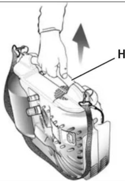
Always use the handle to move the compressor (fig. 4) - Always disconnect power cord and air hose from the air compressor before transporting.
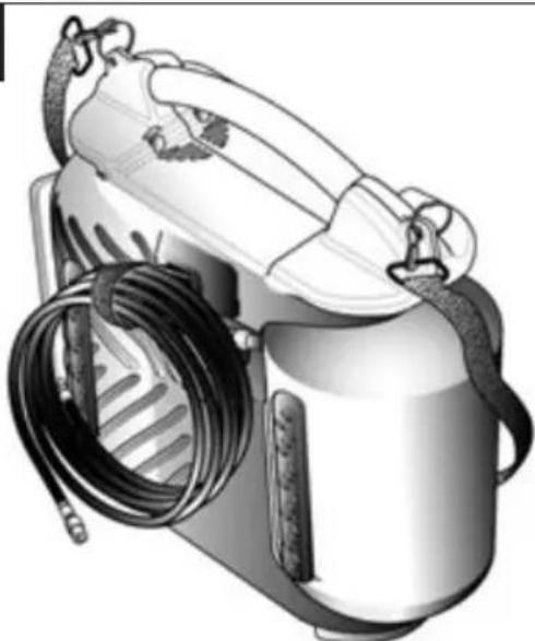
- When operating, the compressor must be placed on a stable, horizontal surface.
- The compressor must only and exclusively be operated in a horizontal position (fig. 1), standing on two strips of rubber located at the opposite side of the control panel.

THINGS NOT TO DO
- Never direct the jet of air towards persons, animals or your body. (Always wear safety goggles to protect against flying objects that may be lifted by the jet of air).
- Never direct the jet of liquids sprayed by tools connected to the compressor towards the compressor.
- Never use the appliance with bare feet or wet hands or feet.
- Never pull the power cable to disconnect the plug from the socket or to move the compressor.
- Never leave the appliance exposed to adverse weather conditions.
- Never transport the compressor with the receiver under pressure.
-
Do not weld or machine the receiver. In the case of faults or rusting, replace the entire receiver.
-
Never allow inexpert persons to use the compressor. Keep children and animals at a distance from the work area.
- This appliance is not intended for use by persons (including children) with reduced physical, sensory or mental capabilities, or lack of experience and knowledge, unless they have been given supervision or instruction concerning the use of the appliance by a person responsible for their safety.
Children should be supervised to ensure that they do not play with the appliance. - Do not position flammable or nylon/fabric objects closed to and/or on the compressor.
- Never clean the compressor with flammable liquids or solvents. Check that you have unplugged the compressor and clean with a damp cloth only.
- The compressor must be used only for air compression. Do not use the compressor for any other type of gas.
- The compressed air produced by the compressor cannot not be used for pharmaceutical, food or medical purposes except after particular treatments and cannot be used to fill the air bottles of scuba divers.
- To avoid serious burns, never touch the cylinder head parts or tubing during or immediately after operation.

THINGS YOU SHOULD KNOW
-
To avoid overheating of the electric motor, this compressor is designed for intermittent operation (do not operate on more than a 15% duty cycle. If this air compressor pumps air more than 15% of one hour, then the compressor's capability is less than the air delivery required by the application. Always match the air volume requirements of the attachment or accessory with the air volume delivery of the compressor). In the case of overheating, the thermal cut-out of the motor tri automatically cutting off the power when the temperature is too high. The motor restarts automatically when normal temperature conditions are restored.
-
When the compressor is plugged into an electrical source and the I/O switch is in the "ON" position, this compressor will cycle automatically.
your—eyever touch any moving parts.
- Keep all body parts, hair, clothing, and jewelry away from moving parts.
-
Never operate the air compressor without all guards and shrouds in place.
-
Never stand on the compressor.
-
The compressor is fitted with a safety valve that is tripped in the case of malfunctioning of the pressure switch in order to assure machine safety.
The red notch on the pressure gauge refers to the maximum operating pressure of the tank. It does not refer to adjusted pressure. -
When fitting a tool, the flow of air in output must be switched off.
-
When using compressed air, you must know and comply with the safety precautions to be adopted for each type of application (inflation, pneumatic tools, painting, washing with water-based detergents only, etc.).
-
Never exceed the maximum allowable pressure recommended by the manufacturer of any attachment or accessory you use with this compressor.
2. FEATURES (Pics. 1-2-3)
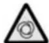
A. I/O Switch: The I/O switch is the activation mechanism that is used to start and stop the compressor. When the switch is "On", the motor and pump will compress air until tank pressure reaches the upper limit of the factory set operating pressure. When tank pressure falls below the factory set "cut in" pressure, the compressor will again automatically start to compress air.
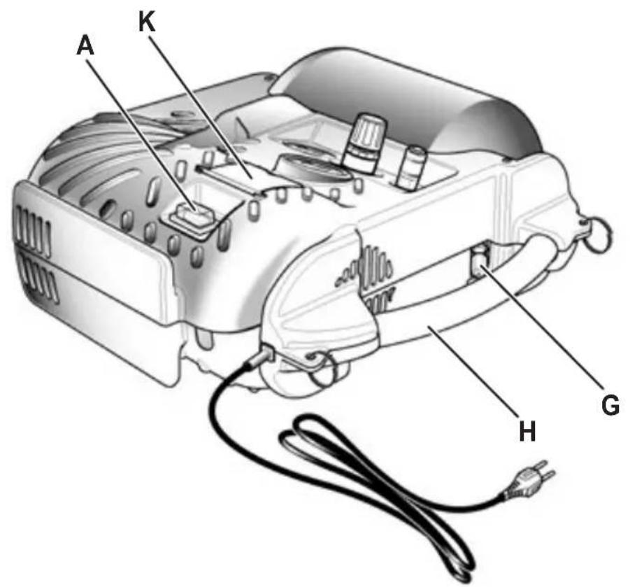
B. Tank Pressure Gauge: The tank pressure gauge indicates the air pressure that is present in the tank in PSI (and BAR).
C. Regulated Pressure Gauge: The regulated pressure gauge indicates the amount of pressure that is allowed into the discharge line according to the setting of the regulator.
D. Regulator Knob: The regulator knob is used to adjust the air pressure that is available at the discharge line. The discharge air pressure is increased by turning the knob clockwise and decreased by turning the knob counter clockwise.
E. Drain Valve: Ball style valve that drains moisture from the tank when opened.
F. Quick Coupler: The quick coupler is used to connect the airline to your tool.
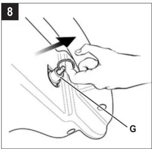
G. Safety valve: The safety valve is set to avoid over-pressurization of the air tanks. This valve is factory pre-set at 10 bar (145 PSI) and will not function unless tank pressure reaches this pressure. Do not attempt to adjust or eliminate this safety device. Any adjustments to this valve could cause serious injury. If this device requires service or maintenance, see an Authorized Service Center.
H. Handle for lifting/moving.
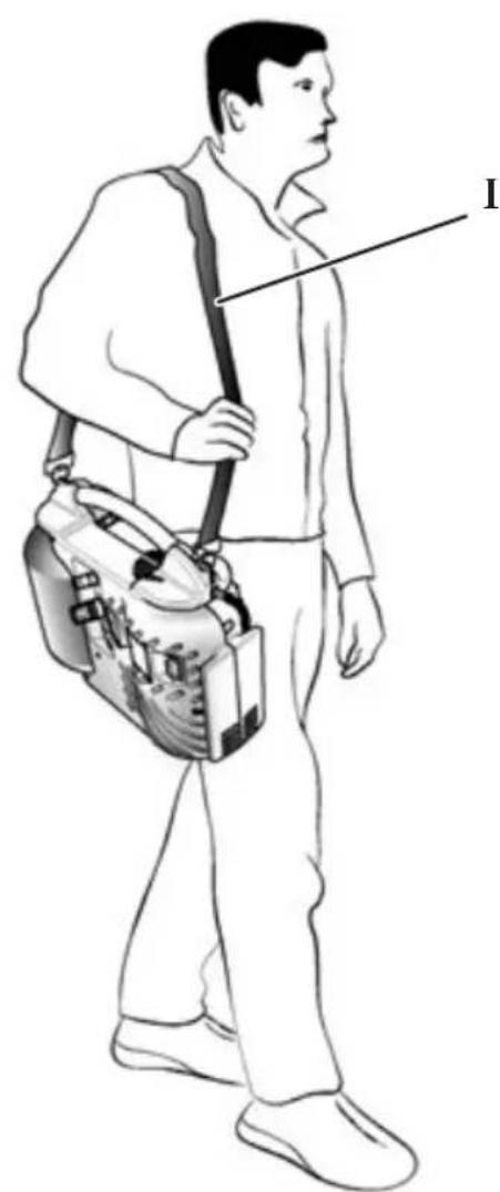
I. Shoulder belt for easy transport and use: The compressor may be conveniently carried using the shoulder belt.
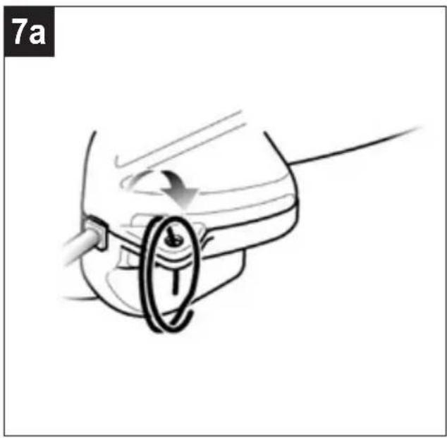
- If the metal rings have not already been fitted, insert the two rings in the two holes in the ends of the aluminium handle (as shown in Figure 7a).
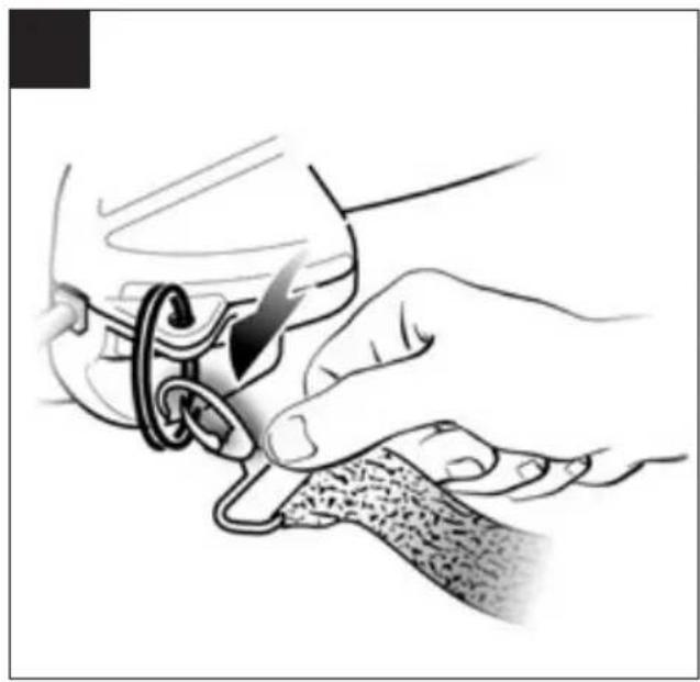
- To fit the belt to the compressor: attach the shoulder strap by inserting the snap hooks into the metal rings on the ends of the handle (as shown in Figure 7b).
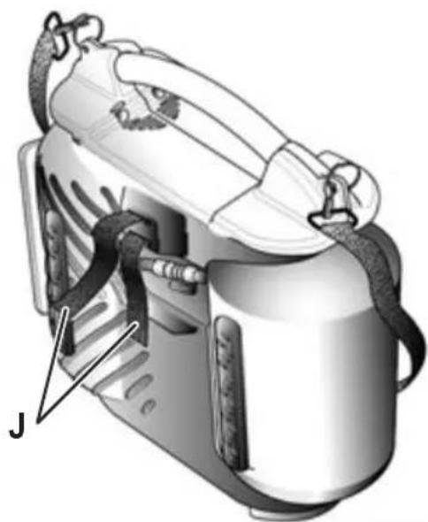
J. Strip attach/detach: The compressor is complete with a Velcro strip. This Velcro strip can be used to secure an air-operated tool (e.g.: nailer) or a PVC extension hose to the body of the compressor (as shown in Figures 6a-6b).
K. Storage box for accessories.
3. SCOPE OF USE
The compressor is designed for generating compressed air for tools operated by compressed air.
Please note that our equipment has not been designed for use in commercial, trade or industrial applications. Our warranty will be voided if the machine is used in commercial, trade or industrial businesses or for equivalent purposes.
The machine is to be used only for its prescribed purpose. Any other use is deemed to be a case of misuse. The user/ operator and not the manufacturer will be liable for any damage or injuries of any kind caused as a result of this.
4. ELECTRICAL GROUNDING INSTRUCTIONS
This product should be electrically grounded. In the event of an electrical short circuit, grounding reduces the risk of electrical shock by providing an escape wire for electrical current. This product is equipped with a cord having a grounding wire with an appropriate grounding plug.
The plug must be plugged into an outlet that is properly installed and grounded in accordance with all local codes and ordinances.
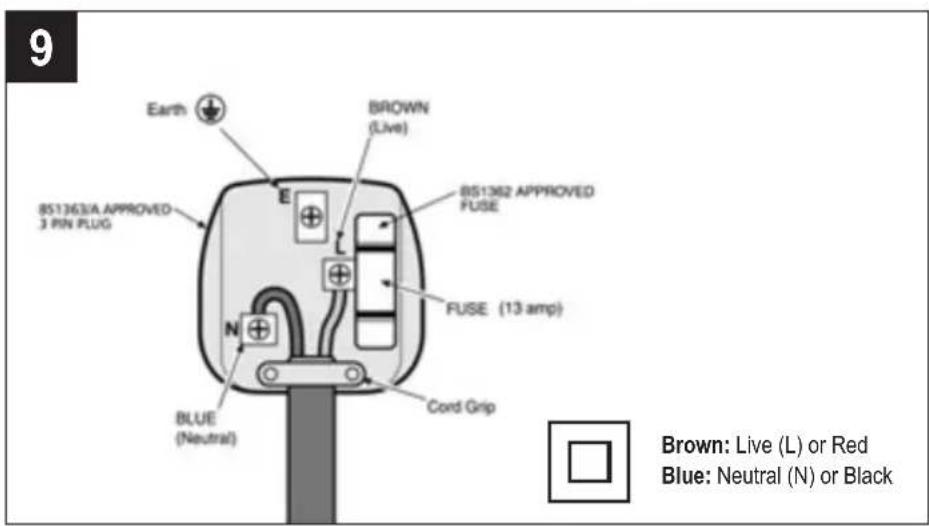
4.1 Connection of the mains plug
Important!
The wires in the mains lead fitted to this product are coloured in accordance with the code shown in pic. 9.
- This product is double insulated and therefore does not require a connection to earth.
The 3 pin plug must comply to BS1363/A. - Fuse must comply to BS1362.
If for any reason the 13 amp plug fitted to this product requires replacement it must be wired in accordance with the following instruction:
Do not connect the brown (live) or blue (neutral) to the earth pin marked 'E' on the 3 pin plug.
- Connect the Blue wire to the terminal marked Neutral (N).
- Connect the Brown wire to the terminal marked Live (L).
- Ensure that the outer insulation is gripped by the cord grip and that the wires are not trapped when replacing the plug cover. The mains lead on this product is fitted with a 13 amp (BS1363/A) plug. A 13 amp (BS1362) fuse must be fitted in the plug.
If in doubt consult a qualified electrician
There are no user serviceable parts inside this product maintenance work on the appliance.
except those referred to in the manual. Alway
servicing to qualified service personnel. Never any part of the casing unless qualified to do so; this unit contains dangerous voltages.

Warning!
For your protection if this product is to be used outdoors it should not be exposed to rain or used in damp locations. Do not place the product on damp surfaces, use a workbench if available. For added protection use a suitable residual current device (R.C.D.) at the socket outlet.
Note: If the mains cable requires replacing it must be replaced with an identical one and fitted by a qualified person.
5. PRE-START PROCEDURES
- Examine the machine for signs of transport Report any damage immediately to the company which delivered the compressor.
- Verify that the tanks have been drained and are clear of any moisture or dirt.
The compressor should be set up near the consumer. - Avoid long air lines and long supply lines (extensions).
Make sure the intake air is dry and dust-free. - Do not set up the compressor in damp or wet rooms.
The compressor may only be used in suitable (with good ventilation and an ambient temperature from 2. +5ircC to +40ircC ). There must be no dust, acids, vapours, explosive gases or inflammable gases in the room. - The compressor is designed to be used in dry rooms. It is prohibited to use the compressor in areas where work is conducted with sprayed water.
6. OPERATION INSTRUCTIONS
6.1 Start-Up Procedures
- Verify that the On/Off switch is in the Off position.
- Verify that the tank air pressure is at 0 PSI.
- Attach the air hose to the discharge line.
- Plug the unit into a properly grounded outlet.
- Push the On/Off switch to On. The O will light-up to indicate the compressor is compressor will automatically cycle on and off to keep the tank pressure maintained.
- Adjust the pressure regulator to the proper setting required for the air tool.
6.2 Shut-Off Procedures
- Push in the On/Off switch to the Off position.
7. CLEANING AND MAINTENANCE

Warning!
Pull the power plug before doing any cleaning and
ysA refer
removeWarning!
Wait until the compressor has completely cooled down. Risk of burns!

Warning!
Always depressurize the tank before carrying out any cleaning and maintenance work.
7.1 Cleaning
- Keep the safety devices free of dirt and dust as possible. Wipe the equipment with a clean cloth or blow it with compressed air at low pressure.
We recommend that you clean the appliance immediately after you use it.
Clean the appliance regularly with a damp cloth and some soft soap. Do not use cleaning agent solvents; these may be aggressive to the plastic parts in the appliance. Ensure that no water can get into the interior of the appliance. - You must disconnect the hose and any spraying tools from the compressor before cleaning. Do not clean the compressor with water, solvents or the like.
the working
7.2 Draining tank
The condensation water must be drained off each day by opening the drain valve (ref. E) (on the bottom of the pressure vessel).
ple that the compressor is turned Off.
- Holding the handle, tilt the compressor toward the drain valve so that they are positioned at the bottom of the tank.
- Turn the drain valve to open the valve.
- Keep the compressor tilted until all moisture has been removed.

Warning!
The condensation water from the pressure vessel will contain residual oil. Dispose of the condensation water in an environmentally compatible manner at the appropriate collection point.
7.3 Safety valve (ref. G)
The safety valve has been set for the highest permitted pressure of the pressure vessel. It is prohibited to adjust the safety valve or remove its seal. Actuate the safety valve from time to time to ensure that it works when required. Pull the ring with sufficient force (fig. 8) until you can hear the compressed air being released. Then release the ring again.
7.4 Storage

Warning!
Pull the mains plug out of the socket and ventilate the appliance and all connected pneumatic tools.
Switch off the compressor and make sure that it is secured in such a way that it cannot be started up
again by any unauthorized person.

Warning!
Store the compressor only in a dry location which is not accessible to unauthorized persons.
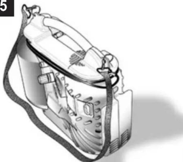
Always store upright, never tilted!
8. DISPOSAL AND RECYCLING
The unit and its accessories are made of various types of material, such as metal and plastic.
Defective components must be disposed of as special waste. Ask your dealer or your local council.
7.4.1 Storage
The compressor may be placed in a vertical position, standing on rubber feet for storage purposes only (as shown in Figure 5).
9. TROUBLESHOOTING GUIDE
Note: Remove power source and drain tank pressure prior to making any repairs or adjustments.
| FAULT CAUSE REMEDY | ||
| Leakage of air from the valve of the pressure switch with the compressor off. | Check valve that, due to wear or dirt on the seal, does not perform its function correctly. | Unscrew the hexagonal head of the check valve, clean the valve seat and the special rubber disk (replace if worn). Reassemble and tighten carefully. |
| Reduction of performance. Frequent start-up. Low pressure values. | Excessive performance request, check for any leaks from the couplings and/or pipes. Intake filter may be clogged. | Replace the seals of the fitting, clean or replace the filter. |
| The compressor stops and restarts automatically after a few minutes. | Tripping of the thermal cutout due to overheating of the motor. | Clean the air ducts in the conveyor. Ventilate the work area. |
| After a few attempts to restart, the compressor stops. | Tripping of the thermal cutout due to overheating of the motor (removal of the plug with the compressor running, low power voltage). | Activate the on/off switch. Ventilate the work area. Wait a few minutes. The compressor will restart independently. |
| The compressor does not stop and the safety valve is tripped. | Irregular functioning of the compressor or breakage of the pressure switch. | Remove the plug and contact the Service Center. |
Any other type of operation must be carried out by authorized Service Centers, requesting original parts. Tampering with the machine may impair its safety and in any case make the warranty null and void.
1. MESURES DE SECURITÉ
3. DOMAINED'APPLICATION
1. VOORZORGSGMAATREGELEN
TI INPENEI NA EEPETE
Tia va aTOPOEUYETAI TUXOv UTEPepavon Tou nAekptiKoU KIVNTnpa, O uMTIEOTnC exei oxEdiaotei yia diakottopevn Aetoupyia (mynr ToV tEtETe OE Aetoupyia yia TEPIOATEPO aTo 15% Tou kukou Aetoupyiac. Eav o aepoouMTIEOTnC avTAEi aepa TEPIOOTPO aTo 15% mias wpa, TOTE n IKAVOTnTA Tou OUMTIOTn Eivai Aiyot aTNO TnV TAPoxn aepa Toun attaTeiTal aTo TNV eapoyn. Na aVTIOAOIXETe TAVTOTE TcattaHTnei Tou oykou aepo TOnpalekOevou n Tou ESApntmuatoc M Te NpaoxN oykou
aepa Tou oumtieotn). Ze TepiTTwn UTEpOepavonc,
EepeyTOIEiTai O eepikoc diakottnc Tou kivtnpa,
diakottovtac autouata tyn Tpofoooia otav n eepokpaia
eivai Tolu uynl. O kivtnpaesTnevekkiveiTai autouata otav
attokaioTavTai o kavovikeoovhkec eepokpaoia.
Otav o oumuTieOTns ouvdeetai me katoia nAektpikn Tnyn kai o biakottns On/Off (epeyotoinons/ atvepeytooinons) evai otn theon "ON" (epeyotoinon), ooumtieTns 8a aeitoupynoe autouata.
Mny ayyicet TE tA KIVOUEVA EApntmuata.
- DiatnpieTe oe antoTaon np Tou owpatoc oac otwca ta paalia, ta pouxka kai ta koogunata aTTO KAIOUmuevaaegaptnmuata.
Mny xeiipceote TOTe Tov aepooumuieotn av Bpiokovtai otn theou ts ta Tpooatautikkai ta kaHmuata.
Mny TATATE TO OUMTHEOTH.
O oumuieotnsivai eGOTIAoEvoc µ ia βλβδααφαλ α
n oToia eVepyOIOeIa OE TepiTTwON duoAeiToupyiac tou
diakontn nieoans yia va eoosaaizetai n aoopaia tou
unxavmuatoC.
H Kokkivn ypaun oTov mepntn Tiean avaepetai OTI meyiotn tiEon aeitoupviaac tsd eaeavnc. dEv avaepetai ot npuOmuevn tiEon.
KataTn ouvdoen evoc TVEUATIKO epaaiou e eva oWAnva meoTOU OTIOUIO BIOXETEUTAI OUMTEIOevoC aepac ATOV aeopooumTeOn, TpeTEI OTWOHNTOTE VA DIAKOITETAI n por TOU aepa aTOY EGOO TOU OwAnva autou.
H xpnoTou TneieoEvou aepa otic diapopec TPOBtioeves xnpoei (pouokwua, TVEmuAtika epyaia, Bao, kaapiaoC ME diautec movo e uatvnaon, kTn.
ev attaiTe t ywOn KAI Tnv npOn TWV TPOBtioeewv KavoviaWv ia Kahe Tepittwngexwpiota.
Mny utepbaive TOTe Tn meyioT n EITPTOpEvn TIEoan Ttou TPOTEIVEIO KATAOKEUAOTn OTIOUOHTOTE PapeAkoEvou n EApntmuatox npoiotioite ME TO OuPTieOt.

2. XAPAKTHPIETIKA (Eikovες 1-2-3)
A. Diakottns On/Off (I/O) (evpyoioinng)
aeepyoioinng): O diakottns eivai o unxavioos
evpyoioanots Tou xnpoiotoieiia yia tnv ekkvnoan kai
tn diakotn aeitoupiaac Tou ouptieotn. Otav o diakottns
eivai oe 0ean "On" (evpyoioan), o kivntnpac kai n
avlia aoumtiezouv aepa xepi n tiean deqaevcns va
ptaoei oto avwato opio tnC epyooataiaka puOmuEvnc
TIeocn aeitoupiaac. Otav n tiean deqaevcns TEeKATW
anto tv npveoataiak paBmuevn tiEon EKKVNOCS, O
oumTietc th a Eeknoei lavau autouata tn ouptieon
aepa.
B. Metpntns piocns dEgauevns: O eTpntns tiocns dEgauevns uToDeikvuei Tnv Tiiean aepa Tou Unpxei OTn dEgauevn oE PSI (kai BAR).
C. Metpntns puoiouevns tioc: O metpntns puoiouevns tieo n utodekvuei tv nootn ta tieo n Tiou eepxetai ot npumn ekponc ouwva e Tn pubion tou puiotn.
D. Kouπi puθιση: To kouπi puθιση xροιμοτοεια γia va puθιζι ην πεση αέρα που είαι διαθεσιμη στη γαμμη εκρός. H πεση αέρα εκρός auδανεται av περιστρεψετε TO kouπi δεξίοτρορα και μειώνεται av περιστρεψετε TO kouπi αριστροστρορα.
E. BaIiδa aiooTpayyions: BaIiδa opaipiko tTou TIO uiaopayyizTnv uypaa atnT n deqevn otav aoivεi.
F. Taxuovvdoos: O taxuovdvaoos xnpoiotroietai ia va ouvdeote tv aywyo aepa me to epyaiao as.
G. Baβiδα ασφαεiας: H βaβiδα ασφαεiας ρθμiζεται γινανατορεύγεται ηιπερβολικό συμτίεοι των δεαμενών αέρα. Autη έβaβiδα εῖαι εργοσταοιακά προμθμιαμένη στα 10 bar (145 PSI) και δεν λειούργει ανη πίεοι έδεαμενός δεν φιαδει autη τήν Πμη. Mνν επιχερησετεν μρθμισετε ἡν ατομακρύνετε autη τήν διαταŋ ασφαεiας.
TuxovpuoieicnbaalidaaTnpoeiv a npokaleouov oepaop tpaumatioe. Eavaut n diataa anaitei oepicn ouvtnpon, aeeuuvtheta e evaxgouioobotmevo kvtpo epic.
2. FUNKCJE (Rys. 1-2-3)
2. LASTNOSTI (Slike 1-2-3)
- Prepnete spinač ZAP/VYP (On/Off) do polohy VYP (Off).
7. ČISTěNÍ A UDRžBA
Pozor!
8.LIKVIDACE A RECYKLACE
1. MEPbI INPEdoCTOPOXHOCTN
Bce noIb3OBaTeN DoJXHbI O3HaKOMTbcra I
noIHOCTbU yCBoNTb BCE CBeDeHnA, CoedePkaunecra B
daHHOM pyKOBOdCTBe NOIb3OBaTeN, Nepei HaaylOM
c6OpKn, 3KcnnyatauHn HIn TexO6CnyxNBAHn
DaHHoro Bo3dyuHoro KOMnPecccopa.
TuaTeIbHo n3yUHTe npuBeDeHHbIe daJee npaBnla B ceJx 6e3oNacHoi 3KcNpyataun IN NOnHOCTbIO ycBOHTe BCE npedynpeXdEHn.
3HaueHne AKYCTNUECKOTo DABJIENRA,
n3MepeHHoro Ha 4 m B CBO6oHOM nOJe,
3KBnBaIeHTHO 3HaueHnIO AKYCTNUECKO
MOUHOCIn, 0603HaueHHoHa JxJToN 3TNKeTKe,
pacnoLoXeHHo Ha KOMnPecCope, MnHyc 20 dB.
PABUNPABOTBI
KOMnpeccopdoJxehpaOtaBbxopoWOBeHTnIpyEmbIX NOMeHnx,piN TeMnepaTypeot +5ircC 1 + 40irc .BBO3dyXe NOMeHnHe DOJXHO CODepXaTbCnbln,NapOB KNCLOT,B3pbIBOONacbIX NnN JERKO BOCNOJaMeHryUoxxCJNkOcTeHnRa3OB.
- Be3onachoe paccToHHe O T pa6oTaUeero KOMnpecccopa - He MeHee 4 M Do MeCTa OCHOBHO pa6oTbI.
- EcIn 6pbI3r npacIbIaemO npn nmoOni KOMnpccop Kpackn nonadaOT Ha 3aunTHbIKoKyx peMe npNBOda, 3NaHT KOMnpccop CTOUT CINUKOM 6NI3KO K MeCTy pa60TbI.
CetBoI pa3bEm IINBnIKN 3NEKtpoPBOJa DOJXeH COOTBeTCTBOBaTb eI NO φOpMe, HApJxKeHIO, YAcTe N COOTBeTCTBOBaTb DeICTByUOuM HopMaMn T6.
- Ecnn Heo6xOIMO nCNOb3OBaTb yDnHHTeB 3neKtponpoB0da, eO dNHa He DoJnxHa npEbbIaTb 5 M, CEHeNe 3neKtpoka6eJa DOJxHo 6bITb He MeHee 1.5 MM².
He pekomeHnyetc HcnoJIb3ObaTb yIHHNTeIb6onbwe IINHb, MHOROKOHtAKTHbIe WTeNCEJI npexoHbIe yCTpoiCTBa.
Bcerda BbIKIOUaHTe KOMPpeccop Haxmna Ha KhoNky BXoD/BbIXOJ.
- Peremeea KOMPecCop, TAHHTe ero ToIbKO npedHa3HaehHyIO dIJI 3TOrO cKOby (pnc.4).
Bcerda otcoeunHnTe uHyp nHTaHn I BO3dyuHbI uHaHr OT BO3dyuHoro KOMnPecccopa nepeD TpaHCnpOpOBkoJ.
Pa6oTaHOuN KOMnPecCOP DOJKeH CToRb Ha yCTOuHBOI ROpN3OHTaJIbHOI NOBepxHOCTn.
KomnpecccopdoJIkeHpa6oTaTbToIbKOBTOp3OHTaIbHOM noIOxehnn (pnc.1), c onopon Ha dBe pe3nHOBbie noIOcbl, pacnoIOxehHHie C npOTnBONoJoxHoCTOpOHbI naHEn ynpabHeHHia.
HE DEJANE 3TOFO
- HanpaBnTb ctpyH cKaTOrO BO3dyxa Ha JIOdei, KINBOTbIX NnHa co6CTBeHHoe TeNo. (YTo6bl co cTpye CKaTOrO BO3dyxa B rna3a He nonaII MEnKHe YactNtBu Ibln, HaneBaIte 3aUHTbIe OcKn).
- HanpaBnTb CtpyU CxAToRO Bo3Dyxa B CTOpOHy camoro KOMIpeccopa.
Pa6oTaTb 6e3 3aIHTHOyBn, Kacatbcra pa6oTaIOUero KOMPpeccopa MOKpbIMpykAMn N/INHOrAMn.
Pe3ko Depratb 3IeKtpoPBOD nHTAHn, BbIKJIOUaY KOMnpecCop n3 cETn, nIIT Ta Hero, NbITaCb CdBHyTb KOMnpecCop c MeCTa.
OCTaBnTb KOMnPecCOp IOD BO3DeIcTBnEM He6IaropnIaTHbIX aTMocΦepHbIX RABHeHNI (doXdb, npMble COJIHeYHbIe LyuH, TymaH, CHer).
-ПepeBo3ntb KOMnpeccop C MeCTa Ha MeCTO, He c6pocNB npedBapntelbHO daBJIeHne n3 pecnBepa. - ПюиЗВОДИТь М_EXАнчЕСКИ PMOHT ИПСВAPКу pecиВера. Рп оБ hapУжЕнДефЕKTOB ИПИ пИЗHAKOB Koppo3И MTeaJIЯ Heo6xOДИМо erO NOIHOCTbIO 3AmeHITb.
-Дуckatb K pa6ote c KOMPpeccopom HeKBaHnФицИрOBaHHbI Ил HeONbIThbIпepcoHaI. He pa3peшаTe np6blnxKaTbCЯ K KomPpeCCopy DeTЯM ИЖIBOTbIM.
OroPn60peHnepeHa3HaueHdIeNcNoJIb3OBaHmNIOBbMn (BKnIOyAaeTei) c OpAHuYeHHbIMNΦN3UeCKUMN, CEHCOPHBIMN IIN yMCTBeHHbIMN CNOco6HOCTAMN INI INPOTCYTCTBNN ONbTA N3HaHm; 3a NCKNIQUHeHMe CnyaEB, KOrda NiUcO, OTBeTCTBeHHoe 3a INx 6e3oNaCHOCTb, Na6JIIOJaET 3a HUMN INI daET IM NHCTpyKcnn npImMeHNIO np6opa.
Heo6xOaHMo cneIHTb, YTO6bI DeTn He nrrpannc npn6opom.
Pa3MeaTb pAOM c KOMnpeccopom JerKo IN BOCnIaMeHAnoueCn IpeDMeTb Nn KnaCTb Ha Kopnyc KOMnpeccopa n3JeNn 13 HeNNoHa n Dpynx JerKo BOCnIaMeHAnuXxCn TkaHei.
- IpoTnpaTb KOpnyc KOMnPecccopa JereKo
BcPnAmHeHJIOUIMMCSr XNIDKOCTAMN. TOnb3yIteCb
NCKHouHTeNbHO CMOueHHo B BOe BetOuHb. He
3a6yDte PpeDbapntbHo OTKnHouHTb KOMnPecccop OT
3JIeKTPocETn.
- IcnoIb3ObaTb KOMnPecCOp dIa CxKaTna HHO r3a, KpOme BO3dyxa.
JaHHbIKOMPpeccop pa3pa6oTah TOnbKO IaIa TeHXHuecknX HxJd.B6OJIbHIuaX,BΦapMaueEBtKe IN DJIa PnIROTOBHeHn PNUsK KOMPpeccopy Heo6xOIMo NOcOeHNrYCTBO npeBaPHTeBHNO NoTOROBKn BO3dyxa.HeJIb3a npImeHrTB KOMPpeccop
ДЯHANoJIHeHnAaKBaJNaHrOB.
BceJx npedOTbpaueHn cepbe3hIx OXoROB, HNKoRaHe KacaTeCb TOnOBbIX YacteI cIIINHnpa IITpy6blBXOe IIN He3aMeDInTEbHO NocIe 3KcNpyatauIN.
CHTO HAD0 3HATb
B ueJx npedotbpaueHn nepepeBa 3neKtpoDBnraTeIa, daHHbIK Kompeccop npedHa3haueH dI npepbIBnctoro pexima 3Knpyataun (He donyckatb erO cyHKUHOHPOBa npi 60nee yem 15% pa6oem zukne. Ecn n BO3dyHbIK KOMPecCOP nepekaHBAET 60nee yem 15% BO3dyxa B TeueHne OndHO Yaca, 3aTEM KOMPecCOPna npOn3BOIDTEbHOCTb 6ydet ABnTbcM Mehbsen noCpABHeHIO C Tpe6yEmoN ondaey Bo3dyxa. Bcerda obEcneuBaT bCOTBETCTBNE Tpe6OBaHm OB3dyxa DOONHHTeBHO rYCTPOcTBa INI npHaNDLeXHocTn HArHeTaHNO Obema Bo3dyxa KOMPecCopa). B cnyae nepeperpeBa, cpa6aTbIAeT TepMOBbIKJUoyateIb DVBraTeIa, abTomaTHueCKN OTKIOUaY IITAHne Pnnp CNIJKOM BbICOKo TEMpepatye. DBiratelb BHOBs 3anyckaetcA abTomaTHeCKN npn BOCCTaHOBJeHN HOpMaJIbHbIX ycNoBIM TEMpepatypbl.
Korda Komnpeccop noKnIOueH K nCTOuHky 3JeKtpoNTaHn, aBbIKNoHTeNb On/Off hAxOJTcR B NoLoXeHH "ON", daHbI KOMnpeccop pa6TaET
ABTOMATNueCKN.
- HnKoIa He KacaTbCb DnBxuXxCyacTei.
- Yactn TeNa, BONocbl, OJekda n yKpaWeHna DOJIKNbI HaxoINTBcB BdAIn OT DnKyUxxCy CAcTei.
-He donyckaTb pa60Ty BO3dyuHoro KOMnPecccopa 6e3 yctaHOBnEHHbIX ORpaKaDeHm N KOxyOB. - HnkOrda He cToaTb Ha KOMnpceccope.
KoMnpccop OcHauE HpeOxpaHHTeHbHbIM KlaPahOM, cpaBaTbIbAIOUIM B CJIyue HeNCpapBHOCTN HpeJe DaBJIeHnB CEJAX rapaHTn 6e3OnaCHOCTn DAHHBpyOBAHn.
KpaCha MeTka Ha upepe6nate MaHOMeTp a 03Haayet MakcmaJIbHoe paOooE daBHeHne pe3epByapa, a He peryIpyEmoe daBHeHne.
- PoiCoeHnHЯ K ⅢNaHry KOMnPecccopa IHeBMOHCTpyMeHT, He 3a6bBAaTe NepeKpbBaTb BO3dUHbI KpaH.
-Пи ИСПОЛБ3OBAHINСКАТОВ 603dUxHAнДУBAHNE,pacblIeHne YpeE3 ПHEBMONHCTpyMeHT,OKpacka,MOKa pactBOPAMN Ha BOHON OCHOBE n.T.I.)co6JIODaTe BCE npabuna T6 ДЯ КЖДOrO KOHKpeTHoro Cnyua.
HnKOrda He npeBbIaTb MaKcImaJIbHOe DoNYCTHMoe DaBJIeHne, peKOMeHNyEMOE 3rTOBOTeNEM DOnOJIHHTeJIbHOro yCTpOJCTBa NII pINHaIJIeXHOCTN, IcNoJIb3yEmbIX C KOMPpeCCOPOM.
2. XAPAKTEPNUCTUKN (Pnc. 1-2-3)
A. IpeeknouateIb On/Off (I/O): IpeeknouateIb IpeIcTabJIeT CO6oM MExaHm3M aKTNbauN, NcIOJIb3yEmbl dIg 3aNyCKa N OCTaHOBKn KOMnpccopa. Korda nepeKnOuateJIb haxoJntcB B NOLOXeHN "On", DBIrTaTeJIb Hacoc CxIMaHT BO3dYx noka daBJeHne 6aKa He DOCTnraet BepxHero IpeJeIpaPboYero DaBJeHna, yCTaHOBNeHHoro Ha 3aBOde. Korda daBJeHne B 6aKe NaJaET HIXe YCTaHOBNeHHoro Ha 3aBOde "OTKJIUOHaOUIeRo" DaBJeHna, KOMnpccop BHOBB HAUNHaET ABTomTuCeCKn CxIMMaTb BO3dYx.
B. MaHometp 6aka: MaHometp 6aka yka3bIbaeT daBneHne BO3dyxa B 6ake, bblpaKeHHoe B ΦYHTAX HA KB.IIOIM (u BAP).
C. OtperynipoBaHHbMaHOMeTp: OTPerynpoBaHHbMaHOMeTp yKa3bIbaet DaBHeHne,OnyCTUMoe Ha IINHn HaHrTaHn B COOTBeTCTBn C yCTaHOBOHyIMN 3HaYeHNMy peryJrTopa.
D. PerynipoBouhna pyka: PerynpoBouhna pyka nCnoIb3yeTcA nnpepyinpoBKn daBneHn BO3dyxa Ha JInHn HarHeTaHn. DaBneHne
BO3dyxa HargHeTaHn yBEnuNbAeTcnyTeM NOBopauNbAHn pyuKn no YacOBn CTpeJIke n UMeHbIaETcnyTeM NOBopauNbAHn pyuKn npOTNB YacOBn CTpeJIkn.
E.CnBHOJ Klanah:UapOBoN Klanan, oBeCneuBaOuNi CInB BnaI n3 6aKa npn erO OTKpbITNI.
F.БbICTpoJeIcTByUOuaMyΦTa: BbICTpoJeIcTByUOua MyΦTa IcNoJIb3yeTcAДЯ NOdCoEINHeHnI INHeBMaTHueCKoJ INHnK INHCTpyMeHTy.
G. IpedoxpanTeBnKnaan:
IpeoxpanTeBnKnaan yctaHOBnEn dna
IpeDynpExeHnYpe3MepHOro daBneHnRAO3dyuNbIX 6akOB.Knaan OtperynipoBaH Ha 3aboJe Ha 10 6ap (145 cyHTOB Ha KB.DIOIM) n He cyHKUOHpyET noka He 6ydet DOCTnHyTo daHHoe daBleHne. He nbTaTecb perynpoBaTb nn CHMaTb daHHoe
IpeoxpanTeBnHOe yCTpOcTBO.
JIobbie perynpOBKn daHHoro Knaana HmryT hAHeCTn cepbe3hN yuep6.Ecn DaHHoe yCTpOcTBo Tpe6ye peMOtta NN TeXo6CnyKunBaHn, o6paTntEcB

aBTOpU3OBaHHbI CepBnChbI ZeHTp.
H. Puyka dnia noDbema/npemeehenia.
I. Pemehdnyo6cbTbA TpaHcnpOpTnOBKn n npimHeHn: Kompeccop MoKeT TpaHCnOpTnPoBaTbcra yO6HbIM 6pb30m npn NOMOuN peMHr.
- EcIIM MeTAnIIuYeCKHe KOJIbUa He 6bIIN MOHTIpOBAHbI npeiBapITeIbHO, BCTaBnTb IBa KOJIbUa B DBA OTBepCTnI, npeyCMOTpeHHbIe Ha KOHcE aIOMMHNeBOI pyKn (Cm. pnc. 7a).
-Дяпстетговая ремнк komпесCopy 3aценть ремен, BCTabля карбиныВ Металичесни Кльца,пpeусмOTpeHHье Ha KOHaxpykN (cM.pnc.7b).
8. YTNJIN3ALUNI N BTOPNUHAR INEPEPA6OTKA
Komnpeccop ero npnaIeJXHocTn COCTOTn3 pa3JIuHbIX MaTePnaIIOB, TaKx KAK HApPImep MetaII IN PnactMacc. YtINs3NpyUte DepeKTHbIe DetanB XeEtx c6opa OcO6bIX OTXODOB. HOpMaUHO 06 3TOM Bbl MoXTe NOLyUHTb B CneuaIaI3NpOBAHHOM MaRa3InHe INN B MeCThBx OpraHax PpaBLeHnA!
9. BO3MOXHbIE HENOJAdkn IN CNOCObl INX YCTPAHEHnA
PpmeaHn: OKnIOHTb nCTOuHnK nTahnN I BblNyCTNTb daBHeHne cIINBHoro 6aka neped npOBedeHnem pemOHtbix pa60t nn perynnpobok.
| HEPONJADKII PIPUHBI | CINOCO6bI YCTPAHEHNI | |
| ПOTERPЯ BO3dYxA chepe3 KJIanah peleДавлиеня ри OCTaNoBLeHOMKOMPpeccope. | Оьрathы Клалан ИЗ-3a ИЗнoca плIЗаграЗнения сеДпobинь клалан He DeprXIT Давлиенie. | ВыИBERHyT b WeecTNirpaHny OToOBkyобрathorO KJIanahа, OчИСТИТсeДЛOBИну I DnCK I N3 CpeZuAnbHOnPe3InbI (eCII IN3HOWeH, TOЗAMeHITb). ПОстБИТ b TOrOBKY HaMeCTO I AKKypaTHO 3aTЯHytB. |
| СнIHЖЕніе KПД.Частіе пуSCN.IПОнЖЕнhoe Давлиенie. | ЧeзМерная Harpy3ka плIВОзMOЖHьп leTOERи B coeДинeHЯnx плI Trpy6ax. Сиьhoe 3aRgP3нeHne BCasCbIBAJOUeToФильТра. | П探测пь у探测ны Harpy3kn.ЗамeHIT b POKJIaDкВ b WtTueperax.OчИСТИТп.IIIN 3aMehITb ФильТр. |
| КOMPpeccop OCTaHaBnIBaETcraI3aTeM, chepe3 HeCKOLbKO MInHyTcamBKNIOuaETcra. | СразыТыВаHne Термпeckо3aUHTb BCNeIeCTBVe NepeRpeBa DBIratela. | ОчИСТИТ b Trpy6oPbOвды ПОДaчИBO3dYxA. П探测пь ПОмeшeHne. |
| KOMPpeccop посе HeCKOLbKxIпОьltOK pUCKa OCTaHaBnIBaETcra. | СразыТа TNLOZaUHTa BCNeIeCTBVe NepeRpeBa DBrIratela (ВыДeрHuTа ИЗ рОЗТКИ ВИЛКaпИТaIOUeTo KaIeЯ пri paBoTaIOUeM KOMPpeccope,ПОнЖeHhOE habPЯжeHne CETn). | П探测пь BblKlIQUaTeIbKOMPpeccop a B NOLOZeHne PnCK.P探测пьnomeшeHne.ВыЖдaTbHeCKOLbKO MInHyT, I KOMPpeccop3aIyCTITcRa ABTomaTNUeCKn. |
| KOMPpeccop He BkLIOuAeTcraIcRaБaIbAeTпpeDoxpAHntelbHniКлapan. | HenРabIVbHajЯ pa6OtaKOMPpeccop плIпОLOmka реIДавлиenia. | ОБecToCHyT b KomPpeccop nOBpaTNTb cZeHTp TexHnueckoiПOMOUsi. |
Bo Bcex octaIbHbIX cnyaX peMOHT kOMnpeccopa dOnJKe H pON3BOIDtbcra Ha CtaHcnn TexHueckoro O6cnykBaHHc nCNoJIb3OBAHHeM oprHaJIbHbIX 3anachbIX qacte. NocTopoHHne BMeaTeNbCTBa npBEdyT K OTMeHe rapaHTnHbIX o83aTeNbCTB pON3BOIDtena.
Du m' oppbevarne donne braksanvisingen sik at du kan sla opp i den ved senere behov
1. SIKKERHETSFORSKRIFTER
6.1 Start Prosedyrer
| ANORMALLIK SEBEP MÜDAHALE | ||
| Luchtlekkage uyt de klep van de pressostaat bij stilstaande compressor. | Kapama vafi aşınma veya pislikten doliayi kapama sirasindo ilelvini hatasıca yapamıyor. | Kapama valfinin altügen kafasınmiş, yuvasıni ve özel lastikli diski temizleyin(agensnı isedehyşir). Yeniden monte edin ve özenle sikişkıncı. |
| Randiman azalmasi. Sık baslatmalar. Alçak basınç değerleri. | Fazla randiman talebi, böglac ve/ veya borulardaki olabilecek siziificantari kontrol edin. Emme filtresi tikanmış olabilir. | Rakor contalarinıdehyşirinfiltry i temizleyin vyadehyşirin. |
| Kompresör duruyor ve bir seks dakika sonra otonom olarak hareket ediyor. | Motorun aşırı isinmasindan doliayi termik koruyucu--,--,--,--,--,--,--,--,--,--,--,--,--,--,--,--,--,--,--,--,--,--,--,--,--,--,--,--,--,--,--,--,--,--,--,--,--,--,--,--,--,--,--,--,--,--,--,--,--,--,--,--,--,--,--,--,--,--,--,--,--,--,--,--,--,--,--,--,--,--,--,--,--,--,--,--,--,--,--,--,--,--,--,--,--,--,--,--,--,--,--,--,--,--,--,--,--,--,--,--,-,--,--,--,--,--,--,--,--,--,--,--,--,--,--,--,--,--,--,--,--,--,--,--,--,--,--,--,--,--,--,--,--,--,--,--,--,--,--,--,--,--,--,--,--,--,--,--,--,--,--,--,--,--,--,--,--,--,--,--,--,--,--,--,--,--,--,--,--,--,--,--,--,--,--,--,--,--,--,--,--,--,--,--,--,--,--,--,--,--,--,--,--,--,--,--,--,--,--,--, -,. Kompresör bir seks denemeden sonra duruyor. | Konveyördeki havaGPCİlerini temizleyin. Mekanı havalandırın. |
| Motorun aşırı isinmasindan doliayi termik koruyucu--,--,--,--,--,--,--,--,--,--,--,--,--,--,--,--,--,--,--,--,--,--,--,--,--,--,--,--,--,--,--,--,--,--,--,--,--,--,--,--,--,--,--,--,--,--,--,--,--,--,--,--,--,--,--,--,--,--,--,--,--,--,--,--,--,--,--,--,--,--,--,--,--,--,--,--,--,-,. Kompresör durmuyor ve emniyet valfı--,--,--,--,--,--,--,--,--,--,--,--,--,--,--,--,--,--,--,--,--,--,--,--,-,. Kompresör bilgeleri ve emniyet valfı--,--,--,--,--,--,--,--,-,. Kompresör bilgeleri ve emniyet valfı--,--,--,--,--,-,. Kompresör bilgeleri ve emniyet valfı--,--,-,. Kompresör bilgeleri ve emniyet valfı--,--,-,. Kompresör bilgeleri ve emniyet valfı--,-,. Kompresör bilgeleri ve emniyet valfı--,-,. Kompresör bilgeleri ve emniyet valfı--,-,. Kompresör bilgeleri ve emniyet valfı--,-,. Kompresör bilgeleri ve emniyet valfı--,-,. Kompresör bilgeleri ve emniyet valfı--,-,. Kompresör bilgelihood of the case of the case of the case of the case of the case of the case of the case of the case of the case of the case of the case of the case of the case of the case of the case of the case of the case of the case of the case of the case of the case of the case of the case of the case of the case of the case of the case of the case of the case of the case of the case of the case of the case of the caseof the case of the case of the case of the case of the case of the case of the case of the case of the case of the case of the case of the case of the case of the case of the case of the case of the case of the case of the case of the case of the case of the case of the case of the case of the case of the case of the case of the case of the case of the case of the case of the case of the case ofthe case of the case of the case of the case of the case of the case of the case of the case of the case of the case of the case of the case of the case of the case of the case of the case of the case of the case of the case of the case of the case of the case of the case of the case of the case of the case of the case of the case of the case of the case of the case of the case of the case of thecase of the case of the case of the case of the case of the case of the case of the case of the case of the case of the case of the case of the case of the case of the case of the case of the case of the case of the case of the case of the case of the case of the case of the case of the case of the case of the case of the case of the case of the case of the case of the case of the case of the case cf the case of the case of the case of the case of the case of the case of the case of the case of the case of the case of the case of the case of the case of the case of the case of the case of the case of the case of the case of the case of the case of the case of the case of the case of the case of the case of the case of the case of the case of the case of the case of the case of the case of thc case of the case of the case of the case of the case of the case of the case of the case of the case of the case of the case of the case of the case of the case of the case of the case of the case of the case of the case of the case of the case of the case of the case of the case of the case of the case of the case of the case of the case of the case of the case of the case of the case of the ccase of the case of the case of the case of the case of the case of the case of the case of the case of the case of the case of the case of the case of the case of the case of the case of the case of the case of the case of the case of the case of the case of the case of the case of the case of the case of the case of the case of the case of the case of the case of the case of the case of the cCase of the case of the case of the case of the case of the case of the case of the case of the case of the case of the case of the case of the case of the case of the case of the case of the case of the case of the case of the case of the case of the case of the case of the case of the case of the case of the case of the case of the case of the case of the case of the case of the case of the case fCase of the case of the case of the case of the case of the case of the case of the case of the case of the case of the case of the case of the case of the case of the case of the case of the case of the case of the case of the case of the case of the case of the case of the case of the case of the case of the case of the case of the case of the case of the case of the case of the case of the c Case of the case of the case of the case of the case of the case of the case of the case of the case of the case of the case of the case of the case of the case of the case of the case of the case of the case of the case of the case of the case of the case of the case of the case of the case of the case of the case of the case of the case of the case of the case of the case of the case of the case Of the case of the case of the case of the case of the case of the case of the case of the case of the case of the case of the case of the case of the case of the case of the case of the case of the case of the case of the case of the case of the case of the case of the case of the case of the case of the case of the case of the case of the case of the case of the case of the case of the case ofthc case of the case of the case of the case of the case of the case of the case of the case of the case of the case of the case of the case of the case of the case of the case of the case of the case of the case of the case of the case of the case of the case of the case of the case of the case of the case of the case of the case of the case of the case of the case of the case of the case of thca case of the case of the case of the case of the case of the case of the case of the case of the case of the case of the case of the case of the case of the case of the case of the case of the case of the case of the case of the case of the case of the case of the case of the case of the case of the case of the case of the case of the case of the case of the case of the case of the case of the Case of the Case of the Case of the Case of the Case of the Case of the Case of the Case of the Case of the Case of the Case of the Case of the Case of the Case of the Case of the Case of the Case of the Case of the Case of the Case of the Case of the Case of the Case of the Case of the Case of the Case of the Case of the Case of the Case of the Case of the Case of the Case of the Case of the Case Of the Case Of the Case Of the Case Of the Case Of the Case Of the Case Of the Case Of the Case Of the Case Of the Case Of the Case OF the Case OF the Case OF the Case OF the Case OF the Case OF the Case OF the Case OF the Case OF the Case OF the Case OF the Case OF the Case OF the Case OF the Case OF the Case OF the Case OF the Case OF the Case OF the Case OF the Case OF the Case OF the Case OF the Case OF the Case OF the Case OF the Case OF the Case OF the Case OF the Case OF the Case OF the Case OF the Case OF the Case OFthe Case OF the Case OF the Case OF the Case OF the Case OF the Case OF the Case OF the Case OF the Case OF the Case OF the Case OF the Case OF the Case OF the Case OF the Case OF the Case OF the Case OF the Case OF the Case OF the Case OF the Case OF the Case OF the Case OF the Case OF the Case OF the Case OF the Case OF the Case OF the Case OF the Case OF the Case OF the Case OF the Case OF theCase OFthe Case OFthe Case OFthe Case OFthe Case OFthe Case OFthe Case OFthe Case OFthe Case OFthe Case OFthe Case OFthe Case OFthe Case OFthe Case OFthe Case OFthe Case OFthe Case OFthe Case OFthe Case OFthe Case OFthe Case OFthe Case OFthe Case OFthe Case OFthe Case OFthe Case OFthe Case OFthe Case OFthe Case OFthe Case OFthe Case OFthe Case OFthe Case OFthe Case OFthe Case Of the Case OFthe Case OFthe Case OFthe Case OFthe Case OFthe Case OFthe Case OFthe Case OFthe Case OFthe Case OFthe Case OFthe Case OFthe Case OFthe Case OFthe Case OFthe Case OFthe Case OFthe Case OFthe Case OFthe Case OFthe Case OFthe Case OFthe Case OFthe Case OFthe Case OFthe Case OFthe Case OFthe Case OFthe Case OFthe Case OFthe Case OFthe Case OFthe Case OFtheCase OFthe Case OFthe Case OFthe Case OFthe Case OFthe Case OFthe Case OFthe Case OFthe Case OFthe Case OFthe Case OFthe Case OFthe Case OFthe Case OFthe Case OFthe Case OFthe Case OFthe Case OFthe Case OFthe Case OFthe Case OFthe Case OFthe Case OFthe Case OFthe Case OFthe Case OFthe Case OFthe Case OFthe Case OFthe Case OFthe Case OFthe Case OFthe Case OFtheCaseOFthe Case OFthe Case OFthe Case OFthe Case OFthe Case OFthe Case OFthe Case OFthe Case OFthe Case OFthe Case OFthe Case OFthe Case OFthe Case OFthe Case OFthe Case OFthe Case OFthe Case OFthe Case OFthe Case OFthe Case OFthe Case OFthe Case OFthe Case OFthe Case OFthe Case OFthe Case OFthe Case OFthe Case OFthe Case OFthe Case OFthe Case OFthe Case OFthe Case OFthc Case OFthe Case OFthe Case OFthe Case OFthe Case OFthe Case OFthe Case OFthe Case OFthe Case OFthe Case OFthe Case OFthe Case OFthe Case OFthe Case OFthe Case OFthe Case OFthe Case OFthe Case OFthe Case OFthe Case OFthe Case OFthe Case OFthe Case OFthe Case OFthe Case OFthe Case OFthe Case OFthe Case OFthe Case OFthe Case OFthe Case OFthe Case OFthe Case OFthe Ccase Of the Ccase Of the Ccase Of the Ccase Of the Ccase Of the Ccase Of the Ccase Of the Ccase Of the Ccase Of the Ccase Of the Ccase Of the Ccase Of the Ccase Of the Ccase Of the Ccase Of the Ccase Of the Ccase Of the Ccase Of the Ccase Of the Ccase Of the Ccase Of the Ccase Of the Ccase Of the Ccase Of the Ccase Of the Ccase Ofthe Ccase Ofthe Ccase Ofthe Ccase Ofthe Ccase Ofthe Ccase Ofthe Ccase Ofthe Ccase Ofthe Ccase Ofthe Ccase Ofthe Ccase Ofthe Ccase Ofthe Ccase Ofthe Ccase Ofthe Ccase Ofthe Ccase Ofthe Ccase Ofthe Ccase Ofthe Ccase Ofthe Ccase Ofthe Ccase Ofthe Ccase Ofthe Ccase Ofthe Ccase Ofthe Ccase OFthe Ccase OFthe Ccase OFthe Ccase OFthe Ccase OFthe Ccase OFthe Ccase OFthe Ccase OFthe Ccase OFthe Ccase OFthe Ccase OFthe Ccase OFthe Ccase OFthe Ccase OFthe Ccase OFthe Ccase OFthe Ccase OFthe Ccase OFthe Ccase OFthe Ccase OFthe Ccase OFthe Ccase OFthe Ccase OFthe Ccase OFthe Ccase OFthe Ccase Ofthe Ccase OFthe Ccase OFthe Ccase OFthe Ccase OFthe Ccase OFthe Ccase OFthe Ccase OFthe Ccase OFthe Ccase OFthe Ccase OFthe Ccase OFthe Ccase OFthe Ccase OFthe Ccase OFthe Ccase OFthe Ccase OFthe Ccase OFthe Ccase OFthe Ccase OFthe Ccase OFthe Ccase OFthe Ccase OFthe Ccase OFthe Ccase Ofthe Ccase Ofthe Ccase OFthe Ccase OFthe Ccase OFthe Ccase OFthe Ccase OFthe Ccase OFthe Ccase OFthe Ccase OFthe Ccase OFthe Ccase OFthe Ccase OFthe Ccase OFthe Ccase OFthe Ccase OFthe Ccase OFthe Ccase OFthe Ccase OFthe Ccase OFthe Ccase OFthe Ccase OFthe Ccase OFthe Ccase OFthe Ccase Ofthe Ccase OFthe Ccase Ofthe Ccase OFthe Ccase OFthe Ccase OFthe Ccase OFthe Ccase OFthe Ccase OFthe Ccase OFthe Ccase OFthe Ccase OFthe Ccase OFthe Ccase OFthe Ccase OFthe Ccase OFthe Ccase OFthe Ccase OFthe Ccase OFthe Ccase OFthe Ccase OFthe Ccase OFthe Ccase OFthe Ccase OFthe Ccase OFthe Ccase Ofthe Ccase Ofthe Ccase Ofthe Ccase OFthe Ccase OFthe Ccase OFthe Ccase OFthe Ccase OFthe Ccase OFthe Ccase OFthe Ccase OFthe Ccase OFthe Ccase OFthe Ccase OFthe Ccase OFthe Ccase OFthe Ccase OFthe Ccase OFthe Ccase OFthe Ccase OFthe Ccase OFthe Ccase OFthe Ccase OFthe Ccase OFthe Ccase Ofthe Ccase OFthe Ccase OFthe Ccase Ofthe Ccase OFthe Ccase OFthe Ccase OFthe Ccase OFthe Ccase OFthe Ccase OFthe Ccase OFthe Ccase OFthe Ccase OFthe Ccase OFthe Ccase OFthe Ccase OFthe Ccase OFthe Ccase OFthe Ccase OFthe Ccase OFthe Ccase OFthe Ccase OFthe Ccase OFthe Ccase OFthe Ccase OFthe Ccase Ofthe Ccase OFthe Ccase Ofthe Ccase Ofthe Ccase OFthe Ccase OFthe Ccase OFthe Ccase OFthe Ccase OFthe Ccase OFthe Ccase OFthe Ccase OFthe Ccase OFthe Ccase OFthe Ccase OFthe Ccase OFthe Ccase OFthe Ccase OFthe Ccase OFthe Ccase OFthe Ccase OFthe Ccase OFthe Ccase OFthe Ccase OFthe Ccase OFthe Ccase Ofthe Ccase Ofthe Ccase OFthe Ccase Ofthe Ccase OFthe Ccase OFthe Ccase OFthe Ccase OFthe Ccase OFthe Ccase OFthe Ccase OFthe Ccase OFthe Ccase OFthe Ccase OFthe Ccase OFthe Ccase OFthe Ccase OFthe Ccase OFthe Ccase OFthe Ccase OFthe Ccase OFthe Ccase OFthe Ccase OFthe Ccase OFthe Ccase OFthe Ccase Ofthe Ccase Ofthe Ccase Ofthe Ccase Ofthe Ccase Ofthe Ccase Ofthe Ccase Ofthe Ccase Ofthe Ccase Ofthe Ccase Ofthe Ccase Ofthe Ccase Ofthe Ccase Ofthe Ccase Ofthe Ccase Ofthe Ccase Ofthe Ccase Ofthe Ccase Ofthe Ccase Ofthe Ccase Ofthe Ccase Ofthe Ccase Ofthe Ccase Ofthe Ccase Ofthe Ccase Ofthe Ccase OFthccase OFthccase OFthccase OFthccase OFthccase OFthccase OFthccase OFthccase OFthccase OFthccase OFthccase OFthccase OFthccase OFthccase OFthccase OFthccase OFthccase OFthccase OFthccase OFthccase OFthccase OFthccase OFthccase OFthccase OFthccase OFthCcase OFthCcase OFthCcase OFthCcase OFthCcase OFthCcase OFthCcase OFthCcase OFthCcase OFthCcase OFthCcase OFthCcase OFthCcase OFthCcase OFthCcase OFthCcase OFthCcase OFthCcase OFthCcase OFthCcase OFthCcase OFthCcase OFthCcase OFthCcase OFthCcase OFth Ccase OFthCcase OFthCcase OFthCcase OFthCcase OFthCcase OFthCcase OFthCcase OFthCcase OFthCcase OFthCcase OFthCcase OFthCcase OFthCcase OFthCcase OFthCcase OFthCcase OFthCcase OFthCcase OFthCcase OFthCcase OFthCcase OFthCcase OFthCcase OFthCcase OFthCaseOfthCcase OfthCcase OfthCcase OfthCcase OfthCcase OfthCcase OfthCcase OfthCcase OfthCcase OfthCcase OfthCcase OfthCcase OfthCcase OfthCcase OfthCcase OfthCcase OfthCcase OfthCcase OfthCcase OfthCcase OfthCcase OfthCcase OfthCcase OfthCcase OfthCcase OfthCcase OFthCcase OFthCcase OFthCcase OFthCcase OFthCcase OFthCcase OFthCcase OFthCcase OFthCcase OFthCcase OFthCcase OFthCcase OFthCcase OFthCcase OFthCcase OFthCcase OFthCcase OFthCcase OFthCcase OFthCcase OFthCcase OFthCcase OFthCcase OFthCcase OfthCcase OfthCcase OfthCcase OfthCcase OfthCcase OfthCcase OfthCcase OfthCcase OfthCcase OfthCcase OfthCcase OfthCcase OfthCcase OfthCcase OfthCcase OfthCcase OfthCcase OfthCcase OfthCcase OfthCcase OfthCcase OfthCcase OfthCcase OfthCcaseOfthCcase OfthCcase OfthCcase OfthCcase OfthCcase OfthCcase OfthCcase OfthCcase OfthCcase OfthCcase OfthCcase OfthCcase OfthCcase OfthCcase OfthCcase OfthCcase OfthCcase OfthCcase OfthCcase OfthCcase OfthCcase OfthCcase OfthCcase OfthCcase OfthCCase OfthCCase OfthCCase OfthCCase OfthCCase OfthCCase OfthCCase OfthCCase OfthCCase OfthCCase OfthCCase OfthCCase OfthCCase OfthCCase OfthCCase OfthCCase OfthCCase OfthCCase OfthCCase OfthCCase OfthCCase OfthCCase OfthCCase OfthCCase OfthCCase OfthCCASEOFthCCaseOFthCCaseOFthCCaseOFthCCaseOFthCCaseOFthCCaseOFthCCaseOFthCCaseOFthCCaseOFthCCaseOFthCCaseOFthCCaseOFthCCaseOFthCCaseOFthCCaseOFthCCaseOFthCCaseOFthCCaseOFthCCaseOFthCCaseOFthCCaseOFthCCaseOFthCCaseOFthCCaseOFthCCaseOFthCCASEOFthCCaseOFthCCaseOFthCCaseOFthCCaseOFthCCaseOFthCCaseOFthCCaseOFthCCaseOFthCCaseOFthCCaseOFthCCaseOFthCCaseOFthCCaseOFthCCaseOFthCCaseOFthCCaseOFthCCaseOFthCCaseOFthCCaseOFthCCaseOFthCCaseOFthCCaseOFthCCaseOFthCCaseOfthCCaseOFthCCaseOFthCCaseOFthCCaseOFthCCaseOFthCCaseOFthCCaseOFthCCaseOFthCCaseOFthCCaseOFthCCaseOFthCCaseOFthCCaseOFthCCaseOFthCCaseOFthCCaseOFthCCaseOFthCCaseOFthCCaseOFthCCaseOFthCCaseOFthCCaseOFthCCaseOFthCCaseOFthCCaseOfthCCASEOFthCCaseOFthCCaseOFthCCaseOFthCCaseOFthCCaseOFthCCaseOFthCCaseOFthCCaseOFthCCaseOFthCCaseOFthCCaseOFthCCaseOFthCCaseOFthCCaseOFthCCaseOFthCCaseOFthCCaseOFthCCaseOFthCCaseOFthCCaseOFthCCaseOFthCCaseOFthCCaseOFthCCaseOthCCaseOthCCaseOthCCaseOthCCaseOthCCaseOthCCaseOthCCaseOthCCaseOthCCaseOthCCaseOthCCaseOthCCaseOthCCaseOthCCaseOthCCaseOthCCaseOthCCaseOthCCaseOthCCaseOthCCaseOthCCaseOthCCaseOthCCaseOthCCaseOthCCase OthCCaseOthCCaseOthCCaseOthCCaseOthCCaseOthCCaseOthCCaseOthCCaseOthCCaseOthCCaseOthCCaseOthCCaseOthCCaseOthCCaseOthCCaseOthCCaseOthCCaseOthCCaseOthCCaseOthCCaseOthCCaseOthCCaseOthCCaseOthCCaseOthCCaseОthCCaseOthCCaseOthCCaseOthCCaseOthCCaseOthCCaseOthCCaseOthCCaseOthCCaseOthCCaseOthCCaseOthCCaseOthCCaseOthCCaseOthCCaseOthCCaseOthCCaseOthCCaseOthCCaseOthCCaseOthCCaseOthCCaseOthCCaseOthCCaseOthCCase.OthCCaseOthCCaseOthCCaseOthCCaseOthCCaseOthCCaseOthCCaseOthCCaseOthCCaseOthCCaseOthCCaseOthCCaseOthCCaseOthCCaseOthCCaseOthCCaseOthCCaseOthCCaseOthCCaseOthCCaseOthCCaseOthCCaseOthCCaseOthCCaseOthCCaseOOthCCaseOthCCaseOthCCaseOthCCaseOthCCaseOthCCaseOthCCaseOthCCaseOthCCaseOthCCaseOthCCaseOthCCaseOthCCaseOthCCaseOthCCaseOthCCaseOthCCaseOthCCaseOthCCaseOthCCaseOthCCaseOthCCaseOthCCaseOthCCaseOthCCaseOVthCCaseOthCCaseOthCCaseOthCCaseOthCCaseOthCCaseOthCCaseOthCCaseOthCCaseOthCCaseOthCCaseOthCCaseOthCCaseOthCCaseOthCCaseOthCCaseOthCCaseOthCCaseOthCCaseOthCCaseOthCCaseOthCCaseOthCCaseOthCCaseOthCCase OVthCCaseOthCCaseOthCCaseOthCCaseOthCCaseOthCCaseOthCCaseOthCCaseOthCCaseOthCCaseOthCCaseOthCCaseOthCCaseOthCCaseOthCCaseOthCCaseOthCCaseOthCCaseOthCCaseOthCCaseOthCCaseOthCCaseOthCCaseOthCCaseOthCCase-OthCCaseOthCCaseOthCCaseOthCCaseOthCCaseOthCCaseOthCCaseOthCCaseOthCCaseOthCCaseOthCCaseOthCCaseOthCCaseOthCCaseOthCCaseOthCCaseOthCCaseOthCCaseOthCCaseOthCCaseOthCCaseOthCCaseOthCCaseOthCCaseOthCCase,OthCCaseOthCCaseOthCCaseOthCCaseOthCCaseOthCCaseOthCCaseOthCCaseOthCCaseOthCCaseOthCCaseOthCCaseOthCCaseOthCCaseOthCCaseOthCCaseOthCCaseOthCCaseOthCCaseOthCCaseOthCCaseOthCCaseOthCCaseOthCCaseOthCCase(OthCCaseOthCCaseOthCCaseOthCCaseOthCCaseOthCCaseOthCCaseOthCCaseOthCCaseOthCCaseOthCCaseOthCCaseOthCCaseOthCCaseOthCCaseOthCCaseOthCCaseOthCCaseOthCCaseOthCCaseOthCCaseOthCCaseOthCCaseOthCCaseOthCCaseothCCaseOthCCaseOthCCaseOthCCaseOthCCaseOthCCaseOthCCaseOthCCaseOthCCaseOthCCaseOthCCaseOthCCaseOthCCaseOthCCaseOthCCaseOthCCaseOthCCaseOthCCaseOthCCaseOthCCaseOthCCaseOthCCaseOthCCaseOthCCaseOthCCase0thCCaseOthCCaseOthCCaseOthCCaseOthCCaseOthCCaseOthCCaseOthCCaseOthCCaseOthCCaseOthCCaseOthCCaseOthCCaseOthCCaseOthCCaseOthCCaseOthCCaseOthCCaseOthCCaseOthCCaseOthCCaseOthCCaseOthCCaseOthCCaseOthCCase'OthCCaseOthCCaseOthCCaseOthCCaseOthCCaseOthCCaseOthCCaseOthCCaseOthCCaseOthCCaseOthCCaseOthCCaseOthCCaseOthCCaseOthCCaseOthCCaseOthCCaseOthCCaseOthCCaseOthCCaseOthCCaseOthCCaseOthCCaseOthCCaseOthCCaseOsTt'3-12-12-12-12-12-12-12-12-12-12-12-12-12-12-12-12-12-12-12-12-12-12-12-12-12-12-12-12-12-12-12-12-12-12 12-12-12-12-12-12-12-12-12-12-12-12-12-12-12-12-12-12-12-12-12-12-12-12-12-12-12-12-12-12-12-12-12- | ||
6.1 Proceduri de pre-pornire
Bbpy DBe rMyeHn JeHTn, NOCTaBeHn Bbpxy CtpHaTa npOTUBONOJXHa Ha KOMaHdHnaHeI.
KAK HE TPRBA DA CE I3PON3BA
He haochbaite Bb3dywHaTcTpy Cpeuy Xopa, JNBOHTNIIN Cpeuy CO6CTBEHOTo CN TAnO (N3noJ3BaIe PpeJa3nOuHa, 3a Da npedotBpaTne NonaadHTo B OChTe HaUyKdTIena, NOBdnHATn OT Bb3dywHaTcTpy).
He haoBaHTe TeHaTa Ctpy, n3XbPnHa OTCBbp3aHnTe KbM KOMnPecopa HnCTpyMeHTN, Cpeuycamra KOMnPecop.
He pa6oTeTe c ypeDa Ha 6oc KpaK nn C MOkpn Pbue n Kpaka.
He IbpaNaTe 3axpaHbAunKa6en, 3a Da OTdeJIInTe Uencena OTOKHTAKTa NIN 3a Da npomeHnTe noLoXeHneTo Ha KOMnpecopa.
He octabraye ypeHa npraKo n3JIOKeHne Ha aTMoccephHTE BInrHn.
He TpaHcnpOpTnpaIte KOMPecopa c HaNrahe B pe3epBoapa.
He n3BbPwBaIte 3aBapKn nn MexaHnHn Opeaun no pe3epBoapa. B cnuya Hn DepeKtn nn yBpeXdHaNn no Hero, cmHaTMy e HaIOxHTenHa.
He no3B0JBaIte nO3BaHTo Ha KOMPecopa OTHeONHTNnIuca.IpeoTbPaTe DoCTbna do pa6oTHataIIIOUaJaHa Deua NxIBOTHn.
To3n ypeH He e npedHa3NaeH 3a n3noJ3BaHe OT Iuca (BkIIOHTeJIHO n Deua) C HamaJIeHN FIn3NuYeCK, CETIN NIN YMCTBeHN CNOcO6HoCT NIN JINCA Ha ONIT N IO3HaHH, OCBEN AKO TE Ca H6JIIODaBAHN INN HNCTpyKTIpaHn KAK Da n3NoJ3BAT TO3n ypeD OT JInCe, OTROBAPrAIO 3a TExHATA 6e3OnaCHOCT.
Ieata Tpra6Ba Da ce HabIoDaBAt, 3a da ce rapaHTnpa, Ye Te He IrgpaT C ypeHa.
He noctabraye do u/nnu Bbpxy komnpecopa IecHO3aJAMMn, HauNoHOBn NnPiATHeHn PpeMeTn.
He noHCTBaIte MaunHaTc JceHc03aJaJIIMTeUHOCTn IIN pa3TBOpHTeN. 3a cenTa H3NON3BaITe eDInHCTBeHo NEKO HABJaxHeHa Kbpna, HO eDBA CneI KaTO yBepuN, Ye UencelbTe N3BaDeH OT eNeKTPnueckn KOHTaKT.
KomnpecopbTe npedHa3haeH 3a cTbCTBaHe Ha Bb3dyx. He n3noJ3BaIte dpyrn BnuOBe ra3 npu pa6ota C Ta3n MaunHa.
-Прон3БЕDEHнгOT Ta3n MaUHnA CrБСТЕнВb3ДуX He може Да ce ИЗПОЛЗВa BbB ФapMaцЕВТИЧАТa, XpaHITeNHO-BkycOBaTа 0бл act N B 6OЛHNYHNTe CTpyKТуп, OCBEN, aKO ПpeДВAPиТELNo He 6bDc
6pa6oTeH,OCBeH TOBa,He e npedHa3HaueH nblHe He H BDOJa3HN 6yTnKn.
3a da n36eHHe Tce cepno3n H3rapaHn, He doKocBaTe HNKora Yactnte Ha cnilnHpObata rnaBa nn Tpb6onpoB0da no BpeMe Ha nn HENocpeDCT cned pa6ota.
3a-ДрьжTe BCnUKN YactN Ha TAnOTo Cn, Kocnte, 6IeKJIoTO n HAKITNTe Cn DaJIeH OT DBrJKeuN Ce YactN.
Ha-He pa6oTeTe HIKORA C Bb3dyuHnKOMnPecOp 6e3
EHO Da Ca NocTaBeHN Ha MrcTO BCNUKN PpeDna3NTeJIN KOxycn.
- He cTBnBaIte HIKORA Bbpxy KOMnPecopa.
KoMnpeocpBt e 06OpyDbaC npedna3eH Klaanah, KOITo ce 3aDenCTBa B CnyaHa Ha HnpaBnHO yHKUHOHPaHe Ha aBTOMata 3a HnraHe, 3a Da HO OHTpyn 6e3ONaCHOCCTTa Ha MaunHaT.
KAKBO TPRBA DA CE 3HAE
3aadaen36berhenpeperpahehaeJeKtpomotopa,T03N KOMPecopepoekTnpan3a pa6ota c npekcbHnA
(He ro octabri Te da pa6oTn no-npOdbJnxTeHNO 15 % ot zukbna Ha pa6ota. Ako To3n BbKOMnpecop n3nomBa B3dyx No-npOdbJnxTeHNO ot 15 % ha cac, toraba npOn3BOiNTeHHocCTTa Ha KOMnpecopa e no-MaIka OT Heo6xOIMOCCTTA ot DOCTABAH B33a npInIOXeHNTo. BuHaRn CbrIacyBaIte BaIHTe NOTpe6HOCTn OT B3dyuWeh o6em Ha npCtABKaT aNn akcecoapa cnpMo B3dyuHnro o6em DoCTABAH OT KOMnpecopa).B cnyaH na ppePraBe ce 3aJeCTBa TepMUnHnT N3KnUoyBateH Na eNEKTPOMOTopa, KOITcnpa abTomatNUHO eNEKTPO3axpaHBAHeto, KOrato Temnepatypata e TBbpDe BvCOKA. ENEKTPOMOTOpBT ce peCtApTnpa ABTomATuH0, KOrato BbDat B3ctAHOBEHn HOpMaJIH NEMpePaTyPHN yCNOBIA.
Korato Κe nceBbT Ha KOMnpecopa e BkapaH B H3TOUHnK Ha eJekTpO3aXpaHBaHe N KJIouybT 3a BKI./ H3Kn. e B No3nCnra "ON" (BKl.), KOMnpecopbT ige 3apa6OTN B cIKbI aBTOMaTHNo.
-HeDOKOCBaIteHnKOraDBNKeUHTeCeYactn.
HHeHOTo DeHHe Bbpxy ypea 3a N3MepBaHe Ha HAnraHe ce OTHacr 3a MaKcImaHOTo pa60THaHaIraHe Ha pe3epBoapa. To He ce OTHacr Do perynnpaHOTo HAnraHe.
e IIO BpemeHa Cbbp3BaHeTo Ha NHeBMaTnueHnHCTpyMeHT KbM HArHeTaTeHNn Tpb6OpBOd Ha KOMnpecopa,
OT 3aIbJnxTeJIHO Tp8Ba Da ce PpeKbcHE Bb3DyUHnRT
NOTOK Ha n3XoDa Ha cbuNra Tpb6OpBOd.
10 Ynotpe6ata Ha cTbCTeH Bb3dyx 3a pa3nUHn HjxDi (HaNyBaHe, NHeBMaTnUHnHCTpyMeHTn, BoaDCBaHe, MneHe C MneU npenapATn Ha BoDA OCHOBaI Dp.)
13NCKBa No3HaBaHeTo n Cna3BaHeTo Ha PpeBnDeHNTe 3a BCEKn OTdeJeH CNyauH HopMN.
He npebuabaTe HNKORA MaKcHMaJIHOTO DOyCTMHO HaJraHe npenOpbUbaHo OT pOn3BoaNTeHa KOaTO I da 6nlo npucTAbKa nn akceCoap, KOraTo n3NoJ3BaTe To3N KOMnpecop.
2. XAPAKTEPNUCTUKN (Φn.r. 1-2-3)
A. KIIOU 3a BKN./m3Kn. (I/O): To3n KIIOU e MEXAHIN3MbT 3a AKTNBIPAHe, KOITO CE n3N0N3Ba 3a nyckaHe n cInpaHe Ha KOMnPecopa. Korato KIIOUbTe Ha "On" (BKn.), eJekTpOMOTOpbT n NOMnata ige KOMPecuPaT Bb3dYxa, DOKATO HAnraHTo B pe3epBoap aDOCTURHe rOpHaTa rpaHua Ha φabpnuHo HAcTPOEHOT pa6oTHo HAnraHe. Korato HAnraHTo B pe3epBoapa naHne noD φabpnuHo HAcTpoEHOTO HAnraHHe Ha "BKIOUbaHe", KOMPecOpbT ue 3aIOUHe ABTOMaTuHO Da KOMPecuPa Bb3dYx.
B. MaHOMeTbP ha pe3epBoapa: MaHOMeTbPbT ha pe3epBoapa NOKa3Ba Bb3dUshOTo HAnrAHe, KOETO HaJIuCe B pe3epBoapa BbB φ yHTObE Ha KB. INH (JIN 6apOBe).
C. PerynpaH MaHometbp: PerynpaHnT MaHometbp NOKa3Ba CToHOCCTTa Ha HAnraHETO, KOeTO Ce IODaBA KbM N3NyckaTeJIHr TaPb6OpBOD CBIpaCHO HAcTpoKkata Ha peryNaTopa.
D. PbKOXBaTKa Ha peryna: PbKOXBaTKaHa perynaTopa ce n3non3Ba 3a perynipaHa Bb3dUshOTo HnraHe, KoTe e Hnue Bn3nyckaTeHnra Tpb6onpoBd. HnraHeTo Ha n3nyckaHe ce yBeJIuHaba Cbc 3abbpTaHe HaPbKOXBaTKata no YacOBnKoBA tCTpeNka HamaJIraBa Ype3 HeHnOTo 3abpTaHe 06paTHo Ha YacOBnKoBA tCTpeNka.
E.ИЗпскATElenBeHTIN:BeHTINOT cfepeHEn TINи3NysKa BnaraTa OT pe3epBoapa, KOraTo 6bJe OTBOpeH.
F.Бbp3oDeiCtBaUcBcEiHHTeI:Bp3oJeCTBaUyT CbeiHHTeI ce n3noJ3Ba 3a CBp3BaHe Ha Bb3dyuHnra Tpb6OpPBOd KbMa Baunr INcTpymENT.
G.Ппeнзгланн:Ппeнзгнгланн e Hаctpoe 3a пeдOTВрТЯВаHe Ha CBpBXHаЯтHe BbB b3dUshnTe pe3epBoApn.To3n KlnanH e ph6pnuHо Habtpoe Ha 10 6apa (145ФуNTa
Ha KB./HnU) HЯMa Da Ce 3aDéηCTBa, OCBeH aKO HaJIraHTo B pe3epBoapa He DoCTnIHe TOBa HaJIraHe. He ce OnNTBaIte Da perynipate nIeIMHHpate TOBa npedna3HO yCTpoiCtBO. BcNqK peryIpOBKn Ha To3n KlaIaN Morat Da npuHrT cepno3HO HapaHBAhe. AKO TOBa yCTpoiCTBO Ce hyKdae OT cepBn3HO o6cnykBaHe IIN IIOdpbXka, CBpKeTe Ce C yIbIHNOMOueH cepBn3EH ueHTbp.
H.Дрьхka 3a BdɪraHe/npehacYe.
I. Pembk 3a pamo 3a Jecho TpaHcnpTupaHe n ynoTpe6a: KompcecopbT moKe da ce npehacn no ydoBeH naH c nomOuTa Ha peBk 3a HocHe.
- Ako MeTaHnTe XaKn He ca MoHTnpaHn PpeBapnteHb, BkapaTe DBeTe XaKn B DaBaTa OTBOPa pa3NoJoxeHN B KpaHa p6KoXBaTKata OT aYmHn (KaTc e Noka3aHo Ha cnpya 7a).
3a da 3aterhepe mbka Ha komnpecopa, 3akaueTe peMbka KaTO BkapaTe KyKITE B MeTaNHTe xaJIKN B KpaHa pBkoXBtKaTa OT anymHn (kaKTo e nokaahO Ha cnpya 7b).
J. Xanka 3a 3akaaye/otkayane: KomnpecopbTe cnaDeH c nenta OT BeIkpO.C nomouTa Ha BeIkpOTo E Bb3MOxHO 3akpenBaHe Ha NHEBMATUeH INCTpyMeHT (HaNPmep: 3aHNTBaUka), INN C yIbJInxTeHnA Tpb6a OT PVC KbM TJIATO HA KOMnpecopa (KaKTO e NOKa3aHo Ha qnr.6a n6b).
K. Kytna 3a cbxpaHbAhe Ha akcecoapn.
3. CΦEPA HA ПРИLOЖЕΗΝΕ
KomnpecopbT cnyx 3a npou3BexkaHeTo Ha Bb3dyx 3a INHCTpyMeHTn, pa6Oteu n Cbc CcbCTeH dyx.
MOna, mMaIte npedBnD, ye HaWnte ypeDu npedHa3HauHeHneTO cH He ca npou3BeHn 3a npomuJleHa, 3aHaTcuNcKa uHn HndyctpnaHn ynotpe6a. Hne He Noemame OTROBOPHOCT, aKO ypeDbT ce npomuJleHn, 3aHaTcuNcKn uHn HndyctpnaHn npednpnTnA, KAKTO n npi paBHOCTOHN DeHOCn.
Maunha Tp6ba da ce n3non3Ba camo no npedha3Ha-ueHneTo. BcKa no-HaTaBbHa n3BbH TOBa ynoTpe6a He e no npedha3NaueHne. 3a npedn3BnKaHN IETN HAPAHABAHNA OT BCaKaBv BnD OTROBOPOCT HOCN nOte6nteT/06cnykBaIOT OJIe, a He npo13-BOIDNTeTJ.
4. BKJIIOUCAHE B MPEXKATA
KoMnpecopbTe cHa6dEn CmpexOB npOboHnK CbC 3a- uHTEN KOHTAKTeH 7e9cEN (230 V ~ 50 Hz). To3n MoKe Da Ce BKnIOuB BvB BCEkN 3auNTEN KOHTAKTeH 7e9cEN, KoiTo e oBe3oNaCeH c 16 A. Ppei NyckaHeTo B EKCnIo- aTaunr OobpHete BHImaHne Ha TOBa, MpeXOBOTo HnpeXeHne Da CbBnaDHe C paBoTHO HAnpeXeHne CnopeT Tabekata 3a napameTpIte Ha MaunHaT. IbItn 3axpaHbaU npoBOHNu, KaKTo N yDbJxNtEIn, Ka6enHn 6apabAHn T.H npeIN3BKNBAt NaH HAnpeXeHneTo N Morat Da Bb3PpeYrTcBAr NyckaHTo Ha DBNrAteJI. Ppi HnCKn TempeaTyprn PoD +5 °C NyckaHTo Ha DBNrAteJIe E 3aTpynHeHO.
2. SANDARA (Pav. 1-2-3)
- Paspauskite On/Off jungiklj ant Off.
2. ÜLEVAADE (Joonised 1-2-3)
É CONFORME ALLE SEGUENTI DISPOSIZIONI - WAS BUILT IN COMPLIANCE WITH THE FOLLOWING DISPOSITIONS
EST CONFORME AUX DISPOSITIONS SUIVANTES - MIT DEN FOLGENDEN VORSCHRIFTEN UBEREINSTIMMT
ESTA CONFORME CON LAS SIGUIENTES DISPOSICIONES - ESTA EM CONFORMIDADE COM AS SEGUIENTES DISPOSICOES
IN OVEREENSTEMMING IS MET DE VOLGENDE BEPALINGEN - OPFYLDER FØLGENDE FORSKRIFTER
ARIOVERNSSTAMMELSE MED FOLJANDE ForesKRIFTER - ALLAOLEVIEN SADOSTEN MUKAISESTI - SYMMOPQNETAI ME T1Z AKOYOQE2IATAEIE
JEST ZGODNA Z NIJEJ WYMIENIONMYI NORMAMI - U SUKLABU SA SLIJEDECIM PROPISIMA - V SKLADU S SLEDECIM ODREDBAMI
MEGFELELO AZ ALABBI RENDETEKNEK - JE V SOULADU S NÁSLEDUJICIMI SMÉRNICEMI - JE V SULADE S NASLEDOVNYMI SMERNICAMI
OTBEUET PEPBOAHNIM CNEUYIOUX HOPMATNBOB -ER I OVERENSSTEMMELSE MED FOLGENDE BESTEMNELSER
IZLEYEN KURALLARA UYGUNLUGUNU BEYAN EDERIZ - A FOST EXECUTAT CONFORM DISPOZITIILOR
E B CbOTBETCTBNE CbC CJIENHTE PA3IOPEBn - U SKLADU SA SLEDECIM PROPISMA - PAGAMINTAS, REMIANTIS SEKANCIOMIS DIREKTYVOMIS


- HORIZONTAL RUNNING
- PRECAUZIONI D'USO
- Preserve this handbook for future reference.
- PRECAUTIONS
- THINGS TO DO
- THINGS NOT TO DO
- THINGS YOU SHOULD KNOW
- FEATURES (Pics. 1-2-3)
- Handle for lifting/moving.
- SCOPE OF USE
- ELECTRICAL GROUNDING INSTRUCTIONS
- Connection of the mains plug
- Important!
- Warning!
- PRE-START PROCEDURES
- OPERATION INSTRUCTIONS
- Start-Up Procedures
- Shut-Off Procedures
- CLEANING AND MAINTENANCE
- Cleaning
- Draining tank
- Safety valve (ref. G)
- Storage
- DISPOSAL AND RECYCLING
- Storage
- TROUBLESHOOTING GUIDE
- MESURES DE SECURITÉ
- DOMAINED'APPLICATION
- VOORZORGSGMAATREGELEN
- TI INPENEI NA EEPETE
- XAPAKTHPIETIKA (Eikovες 1-2-3)
- FUNKCJE (Rys. 1-2-3)
- LASTNOSTI (Slike 1-2-3)
- ČISTěNÍ A UDRžBA
- 8.LIKVIDACE A RECYKLACE
- MEPbI INPEdoCTOPOXHOCTN
- PABUNPABOTBI
- HE DEJANE 3TOFO
- CHTO HAD0 3HATb
- ABTOMATNueCKN.
- XAPAKTEPNUCTUKN (Pnc. 1-2-3)
- Puyka dnia noDbema/npemeehenia.
- YTNJIN3ALUNI N BTOPNUHAR INEPEPA6OTKA
- BO3MOXHbIE HENOJAdkn IN CNOCObl INX YCTPAHEHnA
- Du m' oppbevarne donne braksanvisingen sik at du kan sla opp i den ved senere behov
- SIKKERHETSFORSKRIFTER
- Start Prosedyrer
- Proceduri de pre-pornire
- KAK HE TPRBA DA CE I3PON3BA
- KAKBO TPRBA DA CE 3HAE
- 3aadaen36berhenpeperpahehaeJeKtpomotopa,T03N KOMPecopepoekTnpan3a pa6ota c npekcbHnA
- Korato Κe nceBbT Ha KOMnpecopa e BkapaH B H3TOUHnK Ha eJekTpO3aXpaHBaHe N KJIouybT 3a BKI./ H3Kn. e B No3nCnra "ON" (BKl.), KOMnpecopbT ige 3apa6OTN B cIKbI aBTOMaTHNo.
- XAPAKTEPNUCTUKN (Φn.r. 1-2-3)
- MaHOMeTbP ha pe3epBoapa: MaHOMeTbPbT ha pe3epBoapa NOKa3Ba Bb3dUshOTo HAnrAHe, KOETO HaJIuCe B pe3epBoapa BbB φ yHTObE Ha KB. INH (JIN 6apOBe).
- H.Дрьхka 3a BdɪraHe/npehacYe.
- CΦEPA HA ПРИLOЖЕΗΝΕ
- BKJIIOUCAHE B MPEXKATA
- SANDARA (Pav. 1-2-3)
- ÜLEVAADE (Joonised 1-2-3)
Brand : STANLEY
Model : Airboss DN 200105
Category : Compressor