
SCL - Laser level STANLEY - Free user manual and instructions
Find the device manual for free SCL STANLEY in PDF.
| Brand | Stanley |
| Model | SCL |
| Category | Laser level |
| Leveling accuracy | ≤ 3 mm / 15 m |
| Horizontal / vertical accuracy | ≤ 3 mm / 15 m |
| Compensation range | ± 4° (self-leveling) |
| Working range (line) | ≥ 10 m |
| Working range (with detector) | ≥ 25 m |
| Laser class | Class 2 (EN60825-1) |
| Laser wavelength | 635 nm ± 5 nm |
| Battery life | ≥ 18 hours (alkaline batteries) |
| Power supply | 3 AA batteries |
| Protection rating | IP54 |
| Operating temperature | -10 °C to +50 °C |
| Storage temperature | -25 °C to +70 °C |
| Main functions | Self-leveling, manual mode, pulse mode, pendulum lock |
| Projected beams | Horizontal, vertical, cross |
| Mount | 1/4-20 and 5/8-11 threads for tripod |
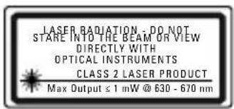
| Safety | Class 2 laser radiation, do not stare into beam |
Frequently Asked Questions - SCL STANLEY
User questions about SCL STANLEY
0 question about this device. Answer the ones you know or ask your own.
Ask a new question about this device
Download the instructions for your Laser level in PDF format for free! Find your manual SCL - STANLEY and take your electronic device back in hand. On this page are published all the documents necessary for the use of your device. SCL by STANLEY.
USER MANUAL SCL STANLEY
2 - Beam Self-Levelling Cross Line Laser
(SCL-D with additional 2 - Beam Spot)
SCL / SCL-D
natural_image
Technical line drawing of a mechanical housing component (no text or symbols)
natural_image
Abstract icon of an open book with a stylized lowercase 'i' and horizontal lines below (no text or symbols)77-320 / 77-321
Please read these instructions before operating the product

Self-Levelling
A
B_1 SCL
B_2 SCL-D

K_1
K_2
K_3
K_4
K_5


M_1
M
M_2
M_3
N_1
N
N_2
N_3
Contents
- Safety
• Product Overview - Keypad, Modes, and LED
- Batteries and Power
- Set Up
- Operation
- Applications
• Accuracy Check and Calibration - Specifications
User Safety

WARNING:
- Carefully read the Safety Instructions and Product Manual before using this product. The person responsible for the instrument must ensure that all users understand and adhere to these instructions.

CAUTION:
- While the laser tool is in operation, be careful not to expose your eyes to the emitting laser beam (red light source). Exposure to a laser beam for an extended time may be hazardous to your eyes.

CAUTION:
- Glasses may be supplied in some of the laser tool kits. These are NOT certified safety glasses. These glasses are ONLY used to enhance the visibility of the beam in brighter environments or at greater distances from laser source.
Retain all sections of the manual for future reference.

WARNING:
- The following label samples are placed on your laser tool to inform of the laser class for your convenience and safety. Please reference the Product Manual for the specifics on a particular product model.
EN 60825-1
Product Overview
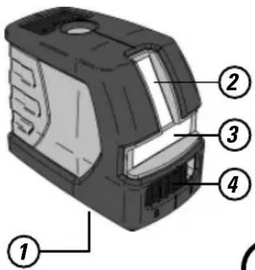
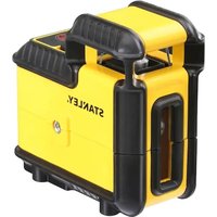
Figure A - Laser Tool
- 1/4 - 20 Threaded Mount
- Window for Vertical Beam Laser
- Window for Horizontal Beam Laser
- Pendulum / Transport Lock
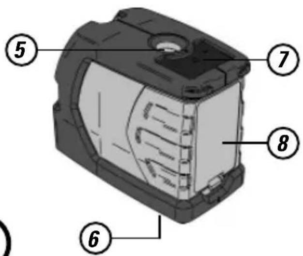
- Window for Up Beam Laser (SCL-D only)
- 5/8 - 11 Threaded Mount Window for Down Beam Laser (SCL-D only)
- Keypad
- Battery Cover
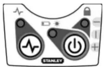
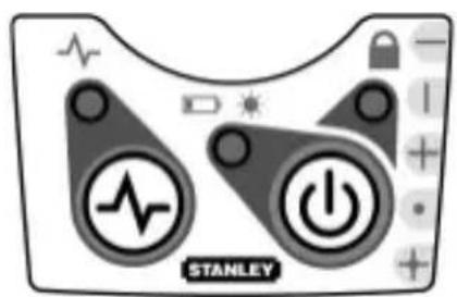
Figure B - Keypad Configurations
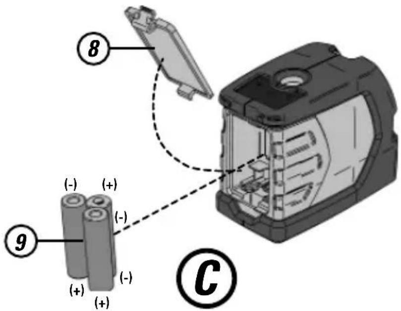
Figure C - Laser Tool Battery Location
- Battery Cover
- Batteries - 3 x "AA"
Figure D - Threaded Mounts
- 1/4 - 20 Threaded Mount
- 5/8 - 11 Threaded Mount
Figure E - Laser Tool on Tripod / Attachment
- Center Screw Thread
- Center Screw Knob
Figure F - Pendulum / Transport Lock Positions
Figure G - Laser Modes
Figure H - Pulse Mode
Figure J - Manual Mode
Figure K - Level Beam Accuracy
Figure L - Horizontal Beam Accuracy
Figure M - Vertical Beam Accuracy
Figure N - Up and Down Beam Accuracy
Keypad, Modes, and LED
Keypads (See figure®)

Power ON / OFF / Mode Key

Pulse Mode ON / OFF Key
Modes (See figure G)

Available Modes (SCL)
- Horizontal Line
- Vertical Line
• Horizontal Line and Vertical Line (Cross) - All beams OFF

Available Modes (SCL-D)
- Horizontal Line
- Vertical Line
• Horizontal Line and Vertical Line (Cross) - Up and Down Dot Beam
- All Line and Dot
- All beams OFF
LEDs (See figure B)

Power LED - Solid GREEN
- Power is ON
Power LED - Blinking RED
- Low Battery
Power LED - Solid RED
- Battery Needs Recharging

Lock LED - Solid RED
- Pendulum lock is ON
- Self-Levelling is OFF
Lock LED - Blinking RED
• Out of Compensation Range

Pulse LED - Solid GREEN
- Pulse Mode is ON
(Can be used with Detector)
Batteries and Power
Battery Installation / Removal
(See figure©)
Laser Tool
- Turn laser tool to back. Open battery compartment cover by pressing and sliding out.
• Install / Remove batteries. Orient batteries correctly when placing into laser tool. - Close and lock battery compartment cover by sliding in until securely closed.

WARNING:
- Pay close attention to the battery holder's (+) and (-) markings for proper battery insertion. Batteries must be of same type and capacity. Do not use a combination of batteries with different capacities remaining.
Set Up
Mounting on Accessories
Tripod / Accessory Mount (See figure(E))
- Position a tripod / accessory in a place where it will not be easily disturbed and near the central location of the area to be measured.
- Set up the tripod / accessory as required. Adjust positioning to be sure tripod head / accessory mounting base is near horizontal.
- Remove the leg attachment from the laser tool for easier mounting.
- Mount the laser tool to the tripod / accessory by pushing up the center screw and tighten (Accessories with either 1/4 or 5/8 thread screw can be used).

CAUTION:
- Do not leave the laser tool unattended on an accessory without fully tightening the center screw. Failing to do so may lead to the laser tool falling and sustaining possible damage.
NOTE:
- It is best practice to always support laser tool with one hand when placing or removing laser tool from an accessory.
- If positioning over a target, partially tighten the center screw, align laser tool, and then fully tighten.
Operation
NOTE:
• See LED Descriptions for indications during operation.
- Before operating the laser tool always be sure to check the laser tool for accuracy.
- In Manual Mode, Self-Levelling is OFF. The accuracy of the beam is not guaranteed to be level.
- Laser tool will indicate when it is out of compensation range. Reference LED Descriptions. Reposition laser tool to be closer to level.
- When not in use, please be sure to power OFF the laser tool and place the pendulum lock in the locked position.
Power
- Press ⏻ to turn laser tool ON.
• To turn laser tool OFF, repeatedly press
until the old for ≥ 3 any mode.
OFF mode is selected OR press and hold seconds to turn laser tool OFF while in an

Mode
- Press repeatedly to cycle through the available modes.
Self-Levelling / Manual Mode
(See Figures Ⓕ and Ⓙ)
- The pendulum lock on the laser tool needs to be switched to the unlocked position to enable self-levelling.
- The laser tool can be used with the pendulum lock in the locked position when it is required to position the laser tool at various angles to project non-level straight lines or points.
Pulse Mode (See Figure H)
- When laser tool is ON, press pulse mode.
- Pulse mode allows use with laser detector.

Applications
Plumb / Point Transfer
- Using the vertical laser beam, establish a vertical reference plane.
- Position the desired object(s) until they are aligned with the vertical reference plane to ensure object(s) are plumb.
(SCL-D only):
- Establish 2 reference points that need to be plumb.
- Align either the down laser beam or the up laser beam to a set reference point.
- The opposing laser beam(s) will be projecting a point which is plumb.
- Position the desired object until the laser beam is aligned with the second reference point that needs to be plumb with the set reference point.
Level / Point Transfer
- Using the horizontal laser beam, establish a horizontal reference plane.
- Position the desired object(s) until they are aligned with the horizontal reference plane to ensure object(s) are level.
Square
- Using the vertical and horizontal laser beams, establish a point where the 2 beams cross.
- Position the desired object(s) until they are aligned with both the vertical and horizontal laser beams to ensure object(s) are square.
Pulse Mode (See Figure Ⓗ)
- Setting laser tool to pulse mode allows use with optional laser detectors.
Manual Mode (See Figures F and J)
- Disables self-levelling function and allows laser unit to project a rigid laser beam in any orientation.
Accuracy Check and Calibration
NOTE:
- The laser tools are sealed and calibrated at the factory to the accuracies specified.
- It is recommended to perform a calibration check prior to its first use and then periodically during future use.
- The laser tool should be checked regularly to ensure its accuracies, especially for precise layouts.
- Transport lock must be in the unlocked position to allow the laser tool to self-level before checking the accuracy.
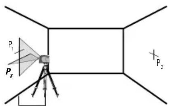
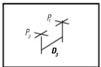
Level Beam Accuracy
(See figure(K))
- Place laser tool as shown with laser ON. Mark point P at cross.
- K_2 Rotate laser tool 180° and mark point P, at cross.
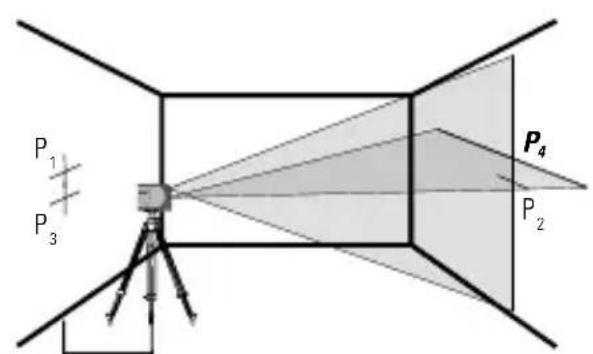
- Move laser tool close to wall and mark point P_3 at cross.
- Rotate laser tool 180° and mark point P _A at cross.
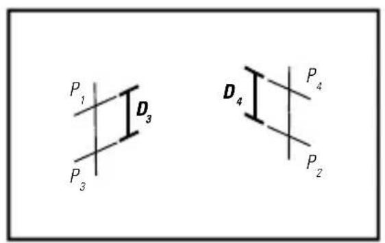
- Measure the vertical distance between P_1 and P_3 to get D_3 and the vertical distance between P_2 and P_4 to get D_4 .
- Calculate the maximum offset distance and compare to the difference of D_3 and D_4 as shown in the equation.
- If the sum is not less than or equal to the calculated maximum offset distance the tool must be returned to your Stanley Distributor for calibration.
Maximum Offset Distance:
$$ \begin{array}{l} = 0, 2 \frac {m m}{m} \times (D _ {1} m - (2 \times D _ {2} m)) \ = 0, 0 0 2 4 \frac {i n}{f t} x \left(D _ {1} f t - (2 x D _ {2} f t)\right) \ \end{array} $$
Compare : (See figure ^K_5 )
$$ D _ {3} - D _ {4} \leq \pm \text { Maximum } $$
Example:
- D_1 = 10m, D_2 = 0.5m
• D_3 = 0.4 mm
• D_4 = -0.6 mm - 0,2 mm /m x (10 m - (2 x 0,5 m) = 1,8 mm (maximum offset distance)
• (0,4 mm) - (-0,6 mm) = 1,0 mm - 1,0 mm ≤ 1,8 mm (TRUE, tool is within calibration)
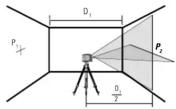
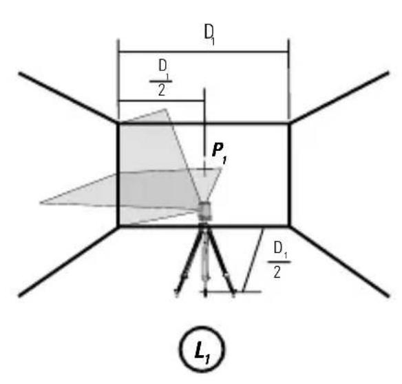
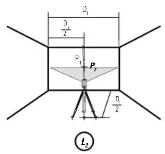
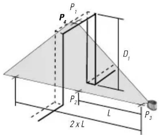
Horizontal Beam Accuracy
(See figure①)
- Place laser tool as shown with laser ON. Aim vertical beam towards the first corner or a set reference point. Measure out half of the distance D_1 and mark point P_1 .
- L_2 Rotate laser tool and align front vertical laser beam with point P_1 . Mark point P_2 where the horizontal and vertical laser beams cross.
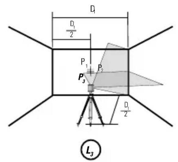
- L_3 Rotate laser tool and aim vertical beam towards the second corner or set reference point. Mark point P_3 so that it is vertically in line with points P_1 and P_2 .
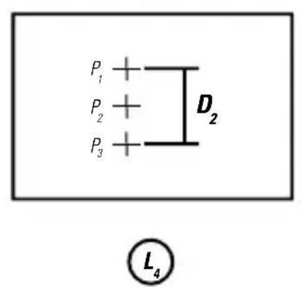
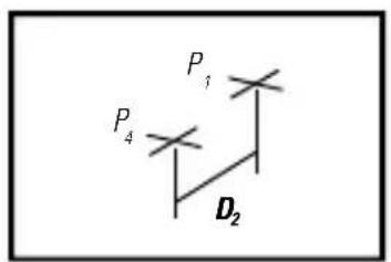
- C_4 Measure the vertical distance D_2 between the highest and lowest point.
- Calculate the maximum offset distance and compare to D2.
- If D_2 s not less than or equal to the calculated maximum offset distance the tool must be returned to your Stanley Distributor for calibration.
Maximum Offset Distance:
$$ \begin{array}{l} = 0, 2 \frac {m m}{m} \times D _ {1} m \ \text { Maximum } \ = 0, 0 0 2 4 \frac {i n}{f t} \times D _ {1} f t \ \end{array} $$
Compare: (See figure ^L_4 )
$$ D _ {2} \leq M a x i m u m $$
Example:
• D_1 = 5 m, D_2 = 0,65 mm
- 0,2 mm /m × 5 m = 1,0 mm (maximum offset distance)
- 0,65 mm ≤ 1,0 mm (TRUE, tool is within calibration)
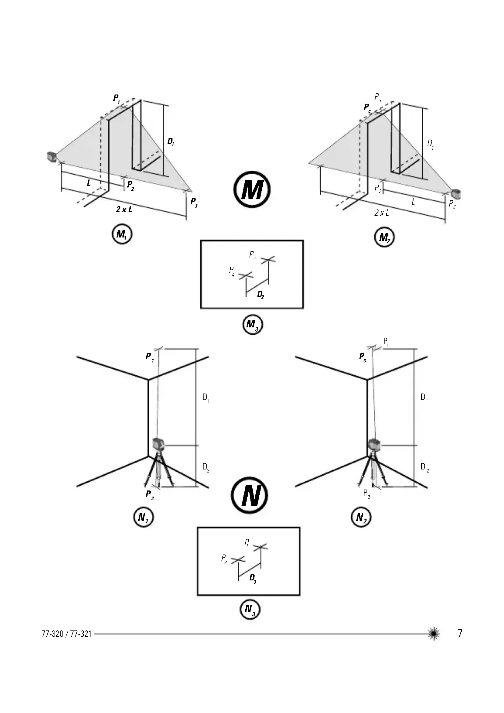
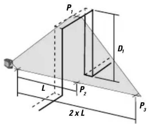
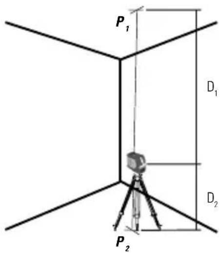
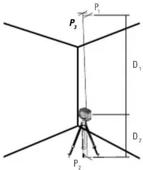
Vertical Beam Accuracy
(See figure ^M )
- Measure the height of a door jamb or reference point to get distance D_1 . Place laser tool as shown with laser ON. Aim vertical beam towards door jamb or reference point. Mark points P_1, P_2 , and P_3 as shown.
- Move laser tool to opposite side of door jamb or reference point and align the same vertical beam with P_2 and P_3 .
- Measure the horizontal distances between P_1 and the vertical beam from the 2nd location.
- Calculate the maximum offset distance and compare to D_2 .
- If 12 s not less than or equal to the calculated maximum offset distance the tool must be returned to your Stanley Distributor for calibration.
Maximum Offset Distance:
$$ \begin{array}{l} = 0, 4 \frac {m m}{m} \times D _ {1} m \ \text { Maximum } \ = 0, 0 0 4 8 \frac {i n}{f t} \times D _ {1} f t \ \end{array} $$
Compare: (See figure ^M_3 )
$$ D _ {2} \leq M a x i m u m $$
Example:
• D_1 = 2m, D_2 = 0.3mm
- 0,4 mm × 2 m = 0,8 mm (maximum offset distance)
- 0,3 ~mm ≤ 0,8 ~mm (TRUE, tool is within calibration)
Up and Down Beam Accuracy
(SCL-D only / See figure N)
- Place laser unit as shown with laser ON. Measure distances D_1 and D_2 . Mark points P_1 and P_2 .
- N_2 Rotate laser unit 180° keeping same distances for D and D₂. Align downward laser beam with point P₂. Mark point P₃.
• N_3 Measure distance D_3 between points P_3 and P_1 . - Calculate the maximum offset distance and compare to D_3 .
- If D_3 is not less than or equal to the calculated maximum offset distance the tool must be returned to your Stanley Distributor for calibration.
Maximum Offset Distance:
$$ \begin{array}{l} = \left(D _ {1} m \times 0. 4 \frac {m m}{m}\right) + \left(D _ {2} m \times 0. 8 \frac {m m}{m}\right) \ = (D _ {1} f t \times 0, 0 0 4 8 \frac {i n}{f t}) + (D _ {2} f t \times 0, 0 0 9 6 \frac {i n}{f t}) \ \end{array} $$
Compare : (See figure ^N_3 )
$$ D _ {3} \leq M a x i m u m $$
Example:
- D_1 = 3m, D_2 = 1m, D_3 = 1,5m
- (3m × 0,4 ) + (1m × 0,8 ) = 2,0mm (maximum offset distance)
- 1,5 ~mm ≤ 2,0 ~mm (TRUE, tool is within calibration)
Specifications
Laser Tool
| SCL SCL-D | ||
| Levelling Accuracy: ≤ 3 mm / 15 m | ||
| Horizontal / Vertical Accuracy ≤ 3 mm / 15 m | ||
| Up Beam Accuracy: ≤ 3 mm / 15 m | ||
| Down Beam Accuracy: ≤ 6 mm / 15 m | ||
| Compensation Range: Self-Levelling to ±4° | ||
| Working Distance: | ||
| Line: ≥ 10 m ≥ 15 m | ||
| with Laser Detector: ≥ 25 m ≥ 50 m | ||
| Dot: ≥ 30 m | ||
| Laser Class: Class 2 (EN60825-1) | ||
| Laser Wavelength 635 nm ± 5 nm | ||
| Operating Time: ≥ 18 hours (Alkaline) | ≥ 10 hours (Alkaline) | |
| Power Source: | 3 x "AA" Batteries | |
| IP Rating: | IP54 | |
| Operating Temperature Range: | -10°C to +50°C | |
| Storage Temperature Range: | -25°C to +70°C | |
Notes

Inhaltsverzeichnis
$$ D _ {2} \leq M a x i m u m $$
Beispiel:
$$ D _ {2} \leq M a x i m u m $$
Beispiel:
Figure G - Modes laser
Figure H - Mode impulsions
Figure J - Mode manuel
Comparer: (Voir figure ^L_4 )
$$ D _ {2} \leq M a x i m u m $$
Exemple :
(Voir figure ^M )
(Consulte as fi guras(F) e (J))
Modo manual (Consulte as figuras F e J)
• Slingervergrendeling is AAN
• Zelfnivellering is UIT
Vergrendeling LED - Knippert ROOD
$$ D _ {2} \leq M a x i m u m $$
Voorbeeld:
- D_1 = 5m, D_2 = 0.65mm
- 0,2 mm / m × 5 m = 1,0 mm (maximum offset afstand)
- 0,65 mm ≤ 1,0 mm (TRUE, apparaat is binnen toleratie)
$$ D _ {2} \leq M a x i m u m $$
Voorbeeld:
- D_1 = 2m, D_2 = 0,3mm
- 0,4 x 2 m = 0,8 mm (maximum offset afstand)
- 0,3 mm ≤ 0,8 mm (TRUE, apparaat is binnen toleratie)
Tastaturer (Se fi gur®)

$$ D _ {2} \leq M a x i m u m $$
Exempel:
(Endast SCL-D / Se Figur N)
$$ = 0, 2 \frac {m m}{m} x (D _ {1} m - (2 x D _ {2} m)) $$
$$ \begin{array}{l} = 0, 0 0 2 4 \frac {t u u m a a}{j a l k a a} x (D _ {j} j a l k a a - (2 \ x D _ {2} f t)) \end{array} $$
Strøm-LED - Blinker R∅DT
- Lavt batteri
Strøm-LED - Konstant R∅D
$$ D _ {2} \leq M a k s i m u m $$
Eksempel:
• D_1 = 5 m, D_2 = 0,65 mm
- 0,2 mm / m x 5 m = 1,0 mm (maksimalt tillatt avviksavstand)
- 0,65 mm ≤ 1,0 mm (SANN, laseren ligger innenfor kalibreringen)
(Kun SCL-D / Se figur N)
$$ D _ {2} \leq M a k s i m u m $$
Przykład:
$$ D _ {2} \leq M a x i m $$
Exemplu:
$$ D _ {2} \leq M a x i m $$
Exemplu:
$$ D _ {2} \leq M a k s i m u m s $$
Piemērs:
$$ D _ {2} \leq M a k s i m u m s $$
Piemērs:
$$ D _ {2} \leq M a k s i m u m a $$
Primjer:
• D_1 = 5 m, D_2 = 0,65 mm
• 0,2 mm × 5 m = 1,0 mm (najveći odmak)
- 0,65 mm ≤ 1,0 mm (ISTINA, alat je unutar raspona kalibracije)
Točnost vertikalne zrake
$$ D _ {2} \leq M a k s i m u m $$
Örnek:
• D_1 = 5 m, D_2 = 0,65 mm
• 0,2 mm /m x 5 m = 1,0 mm (maksimum
• 0,65 mm ≤ 1,0 mm (DOĞRU, alet kalibrasyonda)
© 2010 The Stanley Works
Stanley Europe, Egide Walschaertsstraat 14-16,
2800 Mechelen, Belgium
Issue 1 12/10
WWW.STANLEYWORKS.COM
- - Beam Self-Levelling Cross Line Laser
- SCL / SCL-D
- Contents
- User Safety
- WARNING:
- CAUTION:
- Product Overview
- Figure A - Laser Tool
- Figure B - Keypad Configurations
- Figure C - Laser Tool Battery Location
- Figure D - Threaded Mounts
- Figure E - Laser Tool on Tripod / Attachment
- Keypad, Modes, and LED
- Available Modes (SCL)
- Available Modes (SCL-D)
- LEDs (See figure B)
- Batteries and Power
- Battery Installation / Removal
- Laser Tool
- Set Up
- Mounting on Accessories
- Tripod / Accessory Mount (See figure(E))
- NOTE:
- Operation
- Power
- Mode
- Self-Levelling / Manual Mode
- (See Figures Ⓕ and Ⓙ)
- Pulse Mode (See Figure H)
- Applications
- Plumb / Point Transfer
- (SCL-D only):
- Level / Point Transfer
- Square
- Pulse Mode (See Figure Ⓗ)
- Manual Mode (See Figures F and J)
- Accuracy Check and Calibration
- Level Beam Accuracy
- (See figure(K))
- Maximum Offset Distance:
- Compare : (See figure K_5 )
- Example:
- Horizontal Beam Accuracy
- (See figure①)
- Compare: (See figure L_4 )
- Vertical Beam Accuracy
- (See figure M )
- Compare: (See figure M_3 )
- Up and Down Beam Accuracy
- (SCL-D only / See figure N)
- Compare : (See figure N_3 )
- Specifications
- Notes
- Inhaltsverzeichnis
- Beispiel:
- Comparer: (Voir figure L_4 )
- Exemple :
- (Voir figure M )
- (Consulte as fi guras(F) e (J))
- Modo manual (Consulte as figuras F e J)
- Voorbeeld:
- Exempel:
- (Endast SCL-D / Se Figur N)
- Eksempel:
- (Kun SCL-D / Se figur N)
- Przykład:
- Exemplu:
- Piemērs:
- Primjer:
- Točnost vertikalne zrake
- Örnek:
Brand : STANLEY
Model : SCL
Category : Laser level