
POWEG2010 - Saw PowerPlus - Free user manual and instructions
Find the device manual for free POWEG2010 PowerPlus in PDF.
| Product type | Petrol chainsaw |
| Brand | PowerPlus |
| Model | POWEG2010 |
| Displacement | 56,5 cm³ |
| Max power | 1,2 kW |
| Guide bar length | 355 mm |
| Cutting length | 350 mm |
| Chain pitch | 9,525 mm (3/8") |
| Chain gauge | 1,27 mm (0,05") |
| Max chain speed | 10 500 min⁻¹ |
| Fuel tank capacity | 310 ml |
| Oil tank capacity | 210 ml |
| Chain brake | Yes |
| Anti-vibration system | Yes |
| Drive sprocket | 6 teeth |
| Sound pressure level (LpA) | 97 dB(A) |
| Sound power level (LwA) | 110 dB(A) |
| Vibrations (aw) | ≤5,0 m/s² (K=1,5 m/s²) |
| Fuel type | Petrol/oil mix 40:1 |
| Safety | Chain brake, hand guard, chain catcher |
| Intended use | Domestic use: felling, pruning, cross-cutting |
| Package contents | Saw, guide bar, chain, scabbard, tools (wrenches, file) |
Frequently Asked Questions - POWEG2010 PowerPlus
User questions about POWEG2010 PowerPlus
0 question about this device. Answer the ones you know or ask your own.
Ask a new question about this device
Download the instructions for your Saw in PDF format for free! Find your manual POWEG2010 - PowerPlus and take your electronic device back in hand. On this page are published all the documents necessary for the use of your device. POWEG2010 by PowerPlus.
USER MANUAL POWEG2010 PowerPlus
2 BESCHRIJVING (FIG A)
15 PROBLEEMOPLOSSING
28/06/2022, Lier - Belgium
POWERPLUS POWEG2010 FR
18 DECLARATION OF CONFORMITY


VARO - Vic. Van Rompuy N.V. - Joseph Van Instraat 9 - BE2500 Lier - BELGIQUE, déclare que :
28/06/2022, Lier - Belgium
POWERPLUS POWEG2010 EN
1 INTENDED USE 3
2 DESCRIPTION (FIG A) 3
3 PACKAGE CONTENT LIST 4
4 SYMBOLS 4
5 SAFETY 4
6 KICKBACK SAFETY PRECAUTIONS 5
7 ASSEMBLY 6
7.1 Tools for assembly 6
7.2 Assembly requirements 6
7.3 Guide bar / saw chain / clutch cover installation 7
7.3.1 To install the guide bar.. 7
7.3.2 To install saw chain: 7
7.3.3 Saw chain tension adjustment 7
7.3.4 To adjust saw chain: 8
7.3.5 Chain brake mechanical test.. 8
7.3.6 To test chain brake: 8
8 FUEL AND LUBRICATION. 9
8.1 Fuel 9
8.2 Mixing fuel 9
8.2.1 Fuel and lubrication symbols.. 9
8.2.2 Mixing ratio: 40 parts gasoline to 1 part lubricant 9
8.2.3 Recommended fuels 9
8.2.4 Chain and bar lubrication 9
9 OPERATION. 10
9.1 Engine pre start checks (Fig 8) 10
9.2 Starting a cold engine 10
9.3 Warm start 10
9.4 When engine is saturated with fuel 10
9.5 To stop engine (Fig 9n) 10
9.6 Chain brake operational test 10
9.7 Saw chain / bar lubrication 11
POWERPLUS POWEG2010 EN
9.8 Automatic oiler 11
9.9 General cutting instructions 11
9.9.1 Felling 11
9.9.2 Limbing 12
9.9.3Bucking 13
9.9.4 Bucking using a sawhorse 13
10 MAINTENANCE INSTRUCTIONS 13
10.1 Preventive maintenance 13
10.2 Winter maintenance.. 14
10.3 Air filter 14
10.4 Fuel filter (Fig. 17) 14
10.5 Spark plug 15
11 CLEANING AND MAINTENANCE 15
11.1 Sprocket tip lubrication: 15
11.2 Guide bar maintenance: 16
11.3 Chain sharpening: 16
11.4 Guide bar 17
11.5 Chain maintenance 17
12 TECHNICAL DATA 18
13 NOISE 18
14 STORING A CHAIN SAW 18
15 TROUBLE SHOOTING 19
16 WARRANTY 20
17 ENVIRONMENT 20
18 DECLARATION OF CONFORMITY 21
POWERPLUS POWEG2010 EN
GASOLINE CHAINSAW 37.2CC 350MMPOWEG2010
1 INTENDED USE
These models are intended for infrequent use by homeowners, cottagers, and campers, and for such general applications as clearing, pruning, cutting firewood, etc. They are not intended for prolonged use. If the intended use involves prolonged periods of operation, this may cause circulatory problems in the user's hands due to vibration. Not suitable for professional use.

WARNING! Read this manual and general safety instructions carefully before using the appliance, for your own safety. Your power tool should only be passed on together with these instructions.
2 DESCRIPTION (FIG A)
- Saw chain
- Guide bar
- Chain brake lever / hand guard
- Front handle
- Starter handle
- Stop switch
- Safety trigger
- Rear handle / boot loop
- Oil tank cap
-
Fuel tank cap
-
Guide bar cover
- Bucking spike
- Bar retaining nuts
- Air cleaner cover
- Choke lever
- Saw chain adjustment screw
- Chain catcher
- Throttle trigger
- Adjustment screw for oil supply
-
Primer bulb
-
LOW KICKBACK SAW CHAIN helps significantly reduce kickback or the intensity of kickback, due to specially designed depth gauges and guard links.
-
CHAIN BRAKE is a safety feature designed to reduce the possibility of injury due to kickback by stopping a moving saw chain in milliseconds. It is activated by the Chain Brake lever.
- STOP SWITCH immediately stops the engine when tripped. Stop switch must be pushed to ON position to start or restart engine.
- SAFETY TRIGGER prevents accidental acceleration of the engine. Throttle trigger cannot be squeezed unless the safety latch is depressed.
- CHAIN BRAKE LEVER / HAND GUARD protects the operator's left hand in the event it slips off the front handle while saw is running.
- CHAIN CATCHER reduces the danger of injury in the event saw chain breaks or derails during operation. The chain catcher is designed to intercept a whipping chain.

NOTE: Study your saw and be familiar with its parts.

WARNING! Beware of kickback. Hold chain saw firmly with both hands when using. For your own safety, please read and follow the safety precautions in this manual before attempting to operate your chain saw. Improper use can cause serious injury.

WARNING! When using gas tools, basic safety precautions, including the following, should always be followed to reduce the risk of serious personal injury and/or damage to the unit.
POWERPLUS POWEG2010 EN
3 PACKAGE CONTENT LIST
- Remove all packing materials
- Remove remaining packaging and transit supports (if existing)
- Check the completeness of the packing content
- Check the appliance, the power cord, the power plug and all accessories for transportation damages.
- Keep the packaging materials as far as possible till the end of the warranty period. Disposet it into your local waste disposal system afterwards.

WARNING Packing materials are no toys! Children must not play with plastic bags! Danger of suffocation!
1 x Gasoline chainsaw 37.2CC - 350mm
1 x bottle for 2-cycle lubricant (empty)
1 x Manual
1 x sparkplug key
1xchain
1 x round file
1 x bar
1 x small screwdriver
1 x bar sheath
2 x hex key for fastening chain bar

When parts are missing or damaged, please contact your dealer.
4 SYMBOLS
In this manual and/or on the machine the following symbols are used:
| Wearing of protection against noise advised | Wearing eye protection is advised |
| Always wear gloves | Read manual before usage |
| Denotes risk of personal injury or damage to the tool. | In accordance with essential applicable safety standards of European directives |
5 SAFETY
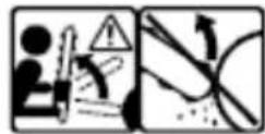
- DO NOT operate a chain saw with one hand! Serious injury to the operator, helpers, bystanders, or any combination of these persons may result from one-handed operation. A chain saw is intended for two-handed use.
DO NOT operate a chain saw when you are fatigued, under the influence of drugs, alcohol or medication. - Use safety footwear, snug-fitting clothing, protective gloves, and eye, hearing and head protection devices.
- Use caution when handling fuel. To avoid fire, move the chain saw at least 10 feet (3m) from the fueling point before starting the engine.
- DO NOT allow other persons to be near when starting or cutting with the chain saw. Keep bystanders and animals out of the work area.
- DO NOT start cutting until you have a clear work area, secure footing, and a planned retreat path from the falling tree.
- Keep all parts of your body away from the saw chain when the engine is running.
- Before you start the engine, make sure that the saw chain is not contacting anything.
POWERPLUS POWEG2010 EN
-
Carry the chain saw with the engine stopped the guide bar and saw chain to the rear, and the muffler away from your body.
-
DO NOT operate a chain saw that is damaged, improperly adjusted, or not completely and securely assembled. Be sure that the saw chain stops moving when the throttle control trigger is released.
-
Shut off the engine before setting the chain saw down.
-
Use extreme caution when cutting small size brush and saplings because slender material may catch the saw chain and be whipped toward you or pull you off balance.
-
When cutting a limb that is under tension, be alert for spring back so that you will not be struck when the tension in the wood fibers is released.
-
Keep the handles dry, clean, and free of oil or fuel mixture.
-
Operate the chain saw only in well-ventilated areas.
DO NOT operate a chain saw in a tree unless you have been specifically trained to do so.
-
All chain saw service, other than the items listed in the user manual safety and maintenance instructions should be performed by competent chain saw service personnel.
-
When transporting your chain saw, use the appropriate guide bar scabbard.
-
DO NOT operate your chain saw near or around flammable liquids or gases whether in or out of doors. An explosion and/or fire may result.
-
Do not fill fuel tank, oil tank or lubricate when the engine is running.
-
USE THE RIGHT TOOL: Cut wood only. Do not use the chain saw for purposes for which it was not intended. For example, do not use the chain saw for cutting plastic, masonry, or non-building materials.
-
The first time user should have practical instruction in the use of chainsaw and the protective equipment from an experienced operator.
-
Do not attempt to hold the saw with one hand only. You cannot control reactive forces and you may lose control of the saw, which can result in the skating or bouncing of the bar and chain along the limb or log.
-
Never run the chainsaw indoors. Your chainsaw produces poisonous exhaust as soon as the combustible engine is started, which may be colorless and odorless. To use this product can generate dust, mists and fumes containing chemicals known to cause reproductive harm. Be aware of harmful dust, mist (such as saw dust or oil mist from chain lubrication) and protect your self properly.
-
Wear gloves and keep your hand warm. Prolonged use of chainsaws exposing the operator to vibrations may produce white finger disease. In order to reduce the risk of white finger disease, please wear gloves and keep your hand warm. If any of the white finger symptoms appear, seek medical advice immediately.
-
Drive in the spiked bumper of the chainsaw directly behind the intended hinge and pivot the saw around this point. The spiked bumper rolls against the trunk.
-
Only chain, guide bar and spark plug can be replaced by the user himself. Always make sure you replace with correct material as stated in the specifications of the manual.
6 KICKBACK SAFETY PRECAUTIONS
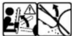
KICKBACK may occur when the NOSE or TIP of the guide bar touches an object, or when wood closes in and pinches the saw chain in the cut.
Tip contact in some cases may cause a lightning-fast reverse reaction, kicking the guide bar up and back toward the operator.
PINCHING the saw chain along the BOTTOM of the guide bar may PULL the saw forward away from the operator.
PINCHING the saw chain along the TOP of the guide bar may PUSH the guide bar rapidly back toward the operator.
POWERPLUS POWEG2010 EN
Any of these reactions may cause you to lose control of the saw, which could result in serious personal injury.
- With a basic understanding of kickback, you can reduce or eliminate the element of surprise. Sudden surprise contributes to accidents.
- Keep a good firm grip on the saw with both hands, the right hand on the rear handle, and the left hand on the front handle, when the engine is running. Use a firm grip with thumbs and fingers encircling the chain saw handles. A firm grip will help you reduce kickback and maintain control of the saw. Don't let go.
- Make sure that the area in which you are cutting is free from obstructions. Do not let the nose of the guide bar contact a log, branch, or any other obstruction which could be hit while you are operating the saw.
- Cut at high engine speeds.
- Do not overreach or cut above shoulder height.
- Follow manufacturer's sharpening and maintenance instructions for the saw chain.
- Only use replacement bars and chains specified by the manufacturer or the equivalent.

NOTE: Low-kickback saw chain is a chain that has met the kickback performance.

WARNING: Kickback can lead to dangerous loss of control of the chain saw and result in serious or fatal injury to the saw operator or to anyone standing close by. Always be alert. Rotational kickback and pinch-kickback are major chain saw operational dangers and the leading cause of most accidents.
Beware of:
Rotational kickback (Fig 1)
A = kickback path
B = kickback reaction zone
The push (pinch kickback) and pull reactions (Fig 2)
A = pull
B = solid objects
C = push
7 ASSEMBLY

Note: described actions below may vary slightly depending on model you purchased.
7.1 Tools for assembly
You will need these tools to assemble your chain saw:
Combination wrench-screwdriver (contained in your user's kit).
- Heavy duty work gloves (user supplied).
7.2 Assembly requirements

Warning: do not start saw engine until unit is properly prepared.
Your new chain saw will require adjustment of chain, filling the fuel tank with correct fuel mixture and filling the oil tank with chain lubricating oil before the unit is ready for operation. Read the entire user manual before attempting to operate your unit. Pay particular attention to all safety precautions.
POWERPLUS POWEG2010 EN
Your user manual is both a reference guide and handbook provided to furnish you with general information to assemble, operate and maintain your saw.
7.3 Guide bar / saw chain / clutch cover installation

Warning: always wear protective gloves when handling chain.
7.3.1 To install the guide bar
To ensure the bar and chain receive oil, only use the original style bar with the oil passage hole (A) as illustrated above. (fig. 3a)
- Make sure the chain brake lever is pulled back into the disengaged position(fig. 3b)
- Remove the bar retaining nut(s) (B). Remove the chain brake cover (C) by pulling straight out, some force may be required. (fig. 3c).
- Place the slotted end of the guide bar over the bar bolt (F). Slide guide bar behind clutch drum (G) until the guide bar stops (fig. 3d).
7.3.2 To install saw chain:
Always wear heavy duty gloves when handling saw chain or making saw chain adjustments.
- Spread chain out in a loop with cutting edges (1) pointing clockwise (fig. 4a).
- Slip the chain around the sprocket (B) behind the clutch (C). Make sure the links fit between the sprocket teeth (fig. 4b).
- Guide the drive links into the groove (D) and around the end of the bar (fig. 4b).

Note: the saw chain may droop slightly on the lower part of bar. This is normal.
- Pull guide bar forward until chain is snug. Ensure all drive links are in the bar groove.
- Install the clutch cover making sure the tang is positioned in the lower hole in the guide bar. Make sure the chain does not slip off of the bar. Install the bar retaining nut hand tight and follow tension adjustment instructions in section saw chain tension adjustment.

Note: the guide bar retaining nuts are installed only hand tight at this point because saw chain adjustment is required. Follow instructions in section saw chain tension adjustment.
7.3.3 Saw chain tension adjustment
Proper tension of saw chain is extremely important and must be checked before starting, as well as during any cutting operation.
Taking the time to make needed adjustments to the saw chain will result in improved cutting performance and prolonged chain life.

Warning: always wear heavy duty gloves when handling saw chain or making saw chain adjustments.
POWERPLUS POWEG2010 EN
7.3.4 To adjust saw chain:
- Hold nose of guide bar up and turn adjustment screw (16) clockwise to increase chain tension. Turning screw counterclockwise will decrease amount of tension on chain. Ensure the chain fits snugly all the way around the guide bar. (fig 5)
- After making adjustment, and while still holding nose of bar in the uppermost position, tighten the bar retaining nuts securely. Chain has proper tension when it has a snug fit all around and can be pulled around by gloved hand.

Note: if chain is difficult to rotate on guide bar or if it binds, too much tension has been applied. This requires minor adjustment as follows:
- Loosen the bar retaining nuts so they are finger tight. Decrease tension by turning the bar adjustment screw counterclockwise slowly. Move chain back and forth on bar. Continue to adjust until chain rotates freely, but fits snugly. Increase tension by turning bar adjustment screw clockwise.
- When saw chain has proper tension, hold nose of bar in the uppermost position and tighten the 2 bar retaining nuts securely.

Caution: a new saw chain stretches, requiring adjustment after as few as 5 cuts. This is normal with a new chain, and the interval between future adjustments will lengthen quickly.

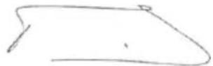
Caution: if saw chain is too loose or too tight, the sprocket, bar, chain, and crankshaft bearings will wear more rapidly. Study fig.6 for information concerning correct cold tension (A), correct warm tension (B), and as a guide for when saw chain needs adjustment (C).
7.3.5 Chain brake mechanical test
Your chain saw is equipped with a chain brake that reduces possibility of injury due to kickback. The brake is activated if pressure is applied against brake lever when, as in the event of kickback, operator's hand strikes the lever. When the brake is actuated, chain movement stops abruptly.

Warning: the purpose of the chain brake is to reduce the possibility of injury due to kickback; however, it cannot provide the intended measure of protection if the saw is operated carelessly. Always test the chain brake before using your saw and periodically while on the job.
7.3.6 To test chain brake:
- The chain brake is disengaged (chain can move) when brake lever is pulled back and locked. Be sure the chain brake latch is in the off position. (fig. 7a)
- The chain brake is engaged (chain is stopped) when brake lever is in forward position and the chain brake latch is in the on position. You should not be able to move chain. (fig. 7b)

Note: the brake lever should snap into both positions. If strong resistance is felt, or lever does not move into either position, do not use your saw. Take it immediately to a professional service center for repair.
Don't let your motor run in high speed when your chainbrake is activated.
POWERPLUS POWEG2010 EN
8 FUEL AND LUBRICATION
8.1 Fuel
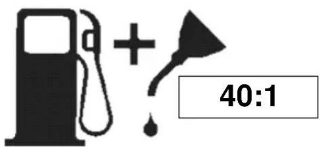
Use regular grade unleaded gasoline mixed with 40:1 custom 2-cycle engine oil for best results. Use mixing ratios in section fuel mixing table below.

Warning: never use straight gasoline in your unit. This will cause permanent engine damage and void the manufacturer's warranty for that product. Never use a fuel mixture that has been stored for over 90 days.

Warning: 2-cycle lubricant must be a premium grade oil for 2-cycle air cooled engines mixed at a 40:1 ratio. Do not use any 2-cycle oil product with a recommended mixing ratio of 100:1. If insufficient lubrication is the cause of engine damage, it voids the manufacturer's engine warranty.
8.2 Mixing fuel
Add oil to an approved fuel container followed by the gasoline to allow incoming gasoline to mix with oil. Shake container to ensure thorough mix.

Warning: Lack of lubrication voids engine warranty. Gasoline and oil must be mixed at 40:1
8.2.1 Fuel and lubrication symbols
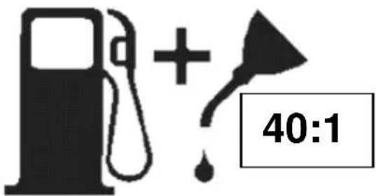

8.2.2 Mixing ratio: 40 parts gasoline to 1 part lubricant
| Gasoline liters | 1 | 2 | 3 | 4 | 5 |
| 2-cycle oil ml | 25 | 50 | 75 | 100 | 125 |
8.2.3 Recommended fuels
Some standard petrols are enriched with oxygen-containing compounds such as alcohol or ether to comply with regulations on clean air. The motor is designed to work well on any car petrol, including these enriched petrol, on the condition that the above mixing ratios are observed!
8.2.4 Chain and bar lubrication
Always refill the chain oil tank each time the fuel tank is refilled. We recommend using our replacement chain & bar. Always use good quality chain oil, which contains additives to reduce friction and wear and to assist in the prevention of pitch formation on the bar and chain
POWERPLUS POWEG2010 EN
9 OPERATION
9.1 Engine pre start checks (Fig 8)

WARNING: Never start or operate the saw unless the bar and chain are properly installed.
- Fill the fuel tank (A) with correct fuel mixture.
- Fill the oil tank (B) with correct chain and bar oil...
9.2 Starting a cold engine
- Activate the chain brake (move the hand guard forward and engage it) (Fig 9a)
To start the saw, push the switch (ON/OFF switch) to the ON (I) position. (Fig. 9b) - Pull out the choke (A) to the point where it latches in place. (Fig. 9c)
- Press primer bulb 3 to 5 times.
- Place the saw on a firm and level surface. Hold the saw securely with your foot as illustrated. Tug sharply on the starter several times until first firing sound is heard. (Fig. 9d)
- Choke will be turned off automatically when you pull the throttle. (Fig. 9e)
- Forcefully pull the starter until the motor engages. (Fig 9f)
- Slightly press in the throttle (Fig 9g)
Pull back the brake lever to release the chain brake (Fig 9h)
9.3 Warm start
- Activate the chain brake (Fig 9i)
- Set the switch (on/off) to ON(I) position (Fig 9j)
- Forcefully pull the starter until the motor engages (Fig 9k)
Slightly press down on the throttle (Fig 9l) - Release the chain brake (Fig 9m)
9.4 When engine is saturated with fuel
- Remove the air filter
- Remove the spark plug
- Position the machine in an angle of 45^ with the sword upwards
Pull the starters rope a few times
Clean the spark plug and place back - Place back the air filter and start without choke
9.5 To stop engine (Fig 9n)
- Release trigger and allow engine to return to idle speed.
- Push the I/O (on/off) switch to O (off) to stop engine.

Note: for emergency stopping, simply activate chain brake and switch the I/O (on/off) switch to o (off).
9.6 Chain brake operational test
Test the chain brake periodically to ensure proper function.
Perform a chain brake test prior to initial cutting, following extensive cutting, and definitely following any chain brake service.
Test chain brake as follows:
- Place saw on a clear, firm, flat surface.
- Start engine.
- Grasp the rear handle (A) with your right hand (fig. 10).
- With your left hand, hold the front handle (B) [not chain brake lever (C)] firmly (fig. 10).
- Squeeze the throttle trigger to 1/3 throttle, then immediately activate the chain brake lever (C) (fig. 10).
POWERPLUS POWEG2010 EN

Warning: activate the chain brake slowly and deliberately. Keep the chain from touching anything; don't let the saw tip forward.
- Chain should stop abruptly. When it does, immediately release the throttle trigger.

Warning: if chain does not stop, turn engine off and take your unit to the nearest authorized service center for service.
- If chain brake functions properly, turn the engine off and return the chain brake to the disengaged position.
9.7 Saw chain / bar lubrication
Adequate lubrication of the saw chain is essential at all times to minimize friction with the guide bar. Never starve the bar and chain of oil. Running the saw with too little oil will decrease cutting efficiency, shorten saw chain life, cause rapid dulling of chain, and cause excessive wear of bar from overheating. Too little oil is evidenced by smoke, bar discoloration or pitch build-up.

Note: saw chain stretches during use, particularly when it is new, and it will occasionally be necessary to adjust and tighten it. New chain will require adjustment after about 5 minutes of operation.
9.8 Automatic oiler
Your chain saw is equipped with an automatic clutch driven oiler system. The oiler automatically delivers the proper amount of oil to the bar and chain. As the engine speed increases, so does the oil flow to the bar pad.

Do not adjust the chain lubrication system unless the motor has been turned off.
The chain lubrication system has been preset to medium oil flow at the factory. The flow can be adjusted if necessary.
-
To adjust the oil flow, turn the adjusting screw at the bottom side of the housing (Fig 11) (19)
-
Turning it clockwise reduces the oil flow, while turning it counterclockwise increases the oil.
9.9 General cutting instructions
9.9.1 Felling
Felling is the term for cutting down a tree. Small trees up to 6-7 inches (15-18cm) in diameter are usually cut in a single cut. Larger trees require notch cuts. Notch cuts determine the direction the tree will fall.
Felling a tree:

Warning: a retreat path (A) should be planned and cleared as necessary before cuts are started. The retreat path should extend back and diagonally to the rear of the expected line of fall, as illustrated in fig. 12a

Caution: if felling a tree on sloping ground, the chain saw operator should keep on the uphill side of the terrain, as the tree is likely to roll or slide downhill after it is felled.
POWERPLUS POWEG2010 EN

Note: direction of fall (B) is controlled by the notching cut. Before any cuts are made, consider the location of larger branches and natural lean of the tree to determine the way the tree will fall.

Warning: do not cut down a tree during high- or changing winds or if there is a danger to property. Consult a tree professional. Do not cut down a tree if there is a danger of striking utility wires; notify the utility company before making any cuts.
General guidelines for felling trees:
Normally felling consists of 2 main cutting operations, notching (C) and making the felling cut (D). Start making the upper notch cut (C) on the side of the tree facing the felling direction (E).
Be sure you don't make the lower cut too deep into the trunk.
The notch (C) should be deep enough to create a hinge (F) of sufficient width and strength.
The notch should be wide enough to direct the fall of the tree for as long as possible.

WARNING: Never walk in front of a tree that has been notched. Make the felling cut (D) from the other side of the tree and 1.5 - 2.0 inches (3-5 cm) above the edge of the notch (C) (Fig. 12b)
Never saw completely through the trunk. Always leave a hinge. The hinge guides the tree. If the trunk is completely cut through, control over the felling direction is lost.
Insert a wedge or felling lever in the cut well before the tree becomes unstable and starts to move. This will prevent the guide bar from binding in the felling cut if you have misjudged the falling direction. Make sure no bystanders have entered the range of the falling tree before you push it over.

Warning: before making the final cut, always recheck the area for bystanders, animals or obstacles.
Felling cut:
-
Use wooden or plastic wedges (A) to prevent binding the bar or chain (B) in the cut. Wedges also control felling (fig. 12c)
-
When diameter of wood being cut is greater than the bar length, make 2 cuts as shown (fig. 12d).

WARNING: As the felling cut gets close to the hinge, the tree should begin to fall. When tree begins to fall, remove saw from cut, stop engine, put chain saw down, and leave area along retreat path (Fig. 12a).
9.9.2 Limbing
Limbing a tree is the process of removing the branches from a fallen tree. Do not remove supporting limbs until after the log is bucked (cut) into lengths (Fig. 13).
Branches under tension should be cut from the bottom up to avoid binding the chain saw.

WARNING: Never cut tree limbs while standing on tree trunk.
POWERPLUS POWEG2010 EN
9.9.3Bucking
Bucking is cutting a fallen log into lengths. Make sure you have a good footing and stand uphill of the log when cutting on sloping ground. If possible, the log should be supported so that the end to be cut off is not resting on the ground. If the log is supported at both ends and you must cut in the middle, make a downward cut halfway through the log and then make the undercut. This will prevent the log from pinching the bar and chain. Be careful that the chain does not cut into the ground when bucking as this causes rapid dulling of the chain. When bucking on a slope, always stand on the uphill side.
- Log supported along entire length: Cut from top (overbuck), being careful to avoid cutting into the ground (Fig. 14a).
- Log supported on 1 end: First, cut from bottom (underbuck) 1/3 diameter of log to avoid splintering. Second, cut from above (overbuck) to meet first cut and avoid pinching (Fig. 14b).
- Log supported on both ends: First, overbuck 1/3 diameter of log to avoid splintering. Second, underbuck to meet first cut and avoid pinching (Fig. 14c)

NOTE: The best way to hold a log while bucking is to use a sawhorse. When this is not possible, the log should be raised and supported by the limb stumps or by using supporting logs. Be sure the log being cut is securely supported.
9.9.4 Bucking using a sawhorse
For personal safety and ease of cutting, the correct position for vertical bucking is essential (fig. 15).
Vertical cutting:
- Hold the saw firmly with both hands and keep the saw to the right of your body while cutting.
- Keep the left arm as straight as possible.
- Keep weight on both feet.

Caution: while the saw is cutting, be sure the chain and bar are being properly lubricated.
10 MAINTENANCE INSTRUCTIONS
All chain saw service, other than items listed here in your user manual maintenance instructions, should be performed by a professional.
10.1 Preventive maintenance
A good preventive maintenance program of regular inspection and care will increase life and improve performance of your chain saw. This maintenance checklist is a guide for such a program. Cleaning, adjustment, and parts replacement may be required, under certain conditions, at more frequent intervals than those indicated.
POWERPLUS POWEG2010 EN
| Maintenance checklist | Each use | Hours of Operation | ||
| Item | Action | 10 | 20 | |
| Screws/nuts/bolts | Inspect/tighten | V | ||
| Air filter | Clean or replace | V | ||
| Fuel filter/oil filter | Replace | V | ||
| Spark plug | Clean/adjust/replace | V | ||
| Fuel hoses | Inspect | V | ||
| Replace as required | ||||
| Chain brake components | Inspect | V | ||
| Replace as required | ||||
10.2 Winter maintenance
Your chain saw requires winter maintenance. Please contact your local dealer for this.
It includes the following:
- Replacing spark plug
- Sharpening the chain
- Cleaning of air filter (Replacement if necessary)
- Cleaning of guide bar
Oil pump check up
Thorough cleanup - Fine tuning and testing
10.3 Air filter

Caution: never operate saw without the air filter. Dust and dirt will be drawn into engine and damage it. Keep the air filter clean!
To clean air filter:
- Remove knob (A) holding air filter cover in place; remove the top cover (B) by loosening the cover retaining screw. Cover will lift off. (fig. 16a)
- Lift the air filter out of air-box (fig. 16b).
- Clean air filter with compressed air. When heavily polluted, wash filter in clean, warm, soapy water. Rinse in clear, cool water. Air dry completely.

Note: it is advisable to have a supply of spare filters.
- Install air filter. Install engine / air filter cover. Make sure latch (E) latch (F) and cover fit properly. Tighten the cover retaining knob securely.

Warning: never perform maintenance when the engine is hot, to avoid any chance of burning hands or fingers.
10.4 Fuel filter (Fig. 17)
- Remove the fuel tank cap.
- Bend a piece of soft wire to from a hook at the end.
- Reach into fuel tank opening and hook fuel line. Carefully pull the fuel line toward the opening until you can reach it with your fingers.

Note: do not pull hose completely out of tank.
POWERPLUS POWEG2010 EN
- Lift filter (A) out of tank.
- Pull filter off with a twisting motion. Discard filter.
- Install new filter. Insert end of filter into tank opening. Make sure filter sits in bottom corner of tank. Use a long screwdriver to aid in filter placement if necessary.
- Fill tank with fresh fuel / oil mixture. See section fuel and lubrication. Install fuel cap.
10.5 Spark plug

Note: for efficient operation of saw engine, spark plug must be kept clean and properly gapped.
- Push stop switch down.
- Remove knob (A) holding air filter cover in place; remove the top cover (B) by loosening the cover retaining screw. Cover will lift off. (fig. 18a)
- Disconnect the wire connector (C) from the spark plug (D) by pulling and twisting at the same time (fig. 18b).
- Remove spark plug with spark plug socket wrench.

DO NOT USE ANY OTHER TOOL
Check electrode gaps with wire feeler gauge and set gaps to .025" (.635mm) if necessary.
- Reinstall a new spark plug.

Note: a resistor spark plug must be used for replacement.
Note: this spark ignition system meets all requirements of the interference-causing equipment regulations.
11 CLEANING AND MAINTENANCE
11.1 Sprocket tip lubrication:

Caution: the sprocket tip on your new saw has been pre-lubricated at the factory. Failure to lubricate the guide bar sprocket tip as explained below will result in poor performance and seizure, voiding the manufacturer's warranty.
Lubrication of the sprocket tip is recommended after 25 hours of use or once a week, which ever occurs first. Always thoroughly clean guide bar sprocket tip before lubrication.
Tools for lubrication:
The lube gun (optional) is recommended for applying grease to the guide bar sprocket tip. The lube gun is equipped with a needle nose tip which is necessary for the efficient application of grease to the sprocket tip.
To lubricate sprocket tip:

Warning: wear heavy duty work gloves when handling the bar and chain.
- Press the stop switch down.
POWERPLUS POWEG2010 EN

Note: it is not necessary to remove the saw chain to lubricate the guide bar sprocket tip. Lubrication can be done on the job.
- Clean the guide bar sprocket tip.
- Using the lube gun (optional), insert needle nose into the lubrication hole and inject grease until it appears at outside edge of sprocket tip (fig. 19).
- Rotate saw chain by hand. Repeat lubrication procedure until the entire sprocket tip has been greased.
11.2 Guide bar maintenance:
Most guide bar problems can be prevented merely by keeping the chain saw well maintained. Insufficient guide bar lubrication and operating the saw with chain that is too tight will contribute to rapid bar wear. To help minimize bar wear, the following guide bar maintenance procedures are recommended.

Warning: always wear protective gloves during maintenance operations. Do not carry out maintenance when the engine is hot.
11.3 Chain sharpening:
For the inexperienced chain saw user, we recommend that the saw chain be professionally sharpened by the nearest professional service center. If you feel comfortable sharpening your own saw chain, special tools are available from the professional service center.
Chain sharpening requires special tools to ensure that cutters are sharpened at the correct angle and depth. For the inexperienced chain saw user, we recommend that the saw chain be professionally sharpened by the nearest professional service center. For non-experienced users of the chain saw, we recommend to have the chain sharpened by a specialist in any authorized service.

Warning: when having wrong sharpened chain, there may occur a higher danger of kickback.
-
To sharpen the saw chain, use the suitable sharpening tools:
-
round chain file
file leading
chain measuring caliber.
These tools can be bought in any specialized stores.
- To gain well shaped sawdust particles, use sharp chain. If there appears wooden powder, you must sharpen the saw chain.

Warning: all cutting teeth must be similarly long. Different length of the teeth can cause rough run of the chain or its rupture, as well.
- Minimum length of the teeth must be 4mm . If they are shorter, remove the saw chain.
- Angles, which the teeth are under, must be followed.
- To sharpen the chain basically, make 2 to 3 pulls of the file from the inside out.

Warning: after 3 to 4 of your sharpening of the cutting teeth, have the saw chain sharpened in any authorized service. They will sharpen the depth limiter as well, which provides the distance.
POWERPLUS POWEG2010 EN
Chain sharpening
The pitch of the chain (fig. 20) depends on the model.
| POWEG2010 | |
| Pitch | 9.525 mm (3/8") |
| Gauge | 1.27 mm (0.05") |
Sharpen the chain using protective gloves and a round file of 5 / 32 (4mm).
Always sharpen the cutters only with outward strokes (fig.21) observing the values given in fig.
- After sharpening, the cutting links must all have the same width and length.

Warning: a sharp chain produces well-defined chips. When your chain starts to produce sawdust, it is time to sharpen.
After every 3-4 times the cutters have been sharpened you need to check the height of the depth gauges and, if necessary, lower them using the flat file and template supplied optional, then round off the front corner. (Fig. 22)

WARNING: Proper adjustment of the depth gauge is as important as proper sharpening of the chain.
11.4 Guide bar
The bar should be reversed every 8 working hours to ensure uniform wear. Keep the bar groove and lubrication hole clean using a bar groove cleaner (optional). (fig. 23) check the bar rails frequently for wear.

Warning: never mount a new chain on a worn sprocket or self-aligning ring.
Oil passages - oil passages on the bar should be cleaned to ensure proper lubrication of the bar and chain during operation.

Note: the condition of the oil passages can be easily checked. If the passages are clear, the chain will automatically give off a spray of oil within seconds of starting the saw. Your saw is equipped with an automatic oiler system.
11.5 Chain maintenance
Chain tension:
Check the chain tension frequently and adjust as often as necessary to keep the chain snug on the bar, but loose enough to be pulled around by hand.
Breaking in a new saw chain:
A new chain and bar will need chain readjustment after as few as 5 cuts. This is normal during the break-in period, and the interval between future adjustments will begin to lengthen quickly.

Warning: never have more than 3 links removed from a loop of chain. This could cause damage to the sprocket.
POWERPLUS POWEG2010 EN
Chain lubrication:
Always make sure the automatic oiler system is working properly. Keep the oil tank filled with good quality chain, bar and chain oil.
Adequate lubrication of the bar and chain during cutting operations is essential to minimize friction with the guide bar.
Never starve the bar and chain of lubricating oil. Running the saw dry or with too little oil will decrease cutting efficiency, shorten saw chain life, cause rapid dulling of chain, and lead to excessive wear of bar from overheating. Too little oil is evidenced by smoke or bar discoloration.
12 TECHNICAL DATA
| Model: | POWEG2010 |
| Engine displacement | 37.2 CC |
| Max .Shaft brake power | 1.2 kW |
| Blade length | 355 mm |
| Bar cutting length | 350mm |
| Chain pitch | 9.525mm (3/8") |
| Chain gauge | 1.27mm (0.05") |
| Idle speed (max) | 3000 min-1 |
| Recommended max. Speed, With cutting attachment | 10500 min-1 |
| Fuel capacity | 310 ml |
| Anti vibration | Yes |
| Drive sprocket | 6 teeth |
| Oil capacity | 210 ml |
| Chain brake | Yes |
13 NOISE
Noise values measured according to relevant standard. (K = 3)
Acoustic pressure level LpA 97 dB(A)
Acoustic power level LwA 110 dB(A)

ATTENTION! Wear hearing protection when sound pressure is over 85 dB(A)
aw (Vibration)
5.0 m/s²
K = 1.5 m/s²
14 STORING A CHAIN SAW
Caution: never store a chain saw for longer than 30 days without performing the following procedures. Storing a chain saw for longer than 30 days requires storage maintenance. Unless the storage instructions are followed, fuel remaining in the carburetor will evaporate, leaving gum-like deposits. This could lead to difficult starting and result in costly repairs.
- Remove the fuel tank cap slowly to release any pressure in tank. Carefully drain the fuel tank.
- Start the engine and let it run until the unit stops to remove fuel from carburetor.
- Allow the engine to cool (approx. 5 minutes).
- Using a spark plug wrench, remove the spark plug.
- Pour 1 teaspoon of clean 2-cycle oil into the combustion chamber. Pull starter rope slowly several times to coat internal components. Replace spark plug. (Fig.24)
POWERPLUS POWEG2010 EN

Note: store the unit in a dry place and away from possible sources of ignition such as a furnace, gas hot water heater, gas dryer, etc.
Removing a unit from storage
- Remove spark plug.
- Pull starter rope briskly to clear excess oil from combustion chamber.
- Clean and gap spark plug or install a new spark plug with proper gap.
Prepare unit for operation. - Fill fuel tank with proper fuel / oil mixture. See fuel and lubrication section
15 TROUBLE SHOOTING
| PROBLEM | PROBABLE CAUSE | CORRECTIVE ACTION |
| Unit won't start or starts but will not run. | Incorrect starting procedures.Incorrect carburetor mixture adjustment setting.Fouled spark plugEmpty fuel tank.Primer bulb was not pressed enough. | Follow instructions in the user manual.Have carburetor adjusted by an authorized service centerCLEAN/gap or replace plug.Fill fuel tank with properly mixed fuel. |
| Unit starts, but engine has low power. | Fuel filter is plugged.Incorrect lever position.Dirty spark arrester screen.Dirty air filter.Incorrect carburetor mixture adjustment setting service dealer. | Replace the fuel filter.Move to run position.Replace spark arrester screen.Remove, clean and reinstall filter.Have carburetor adjusted by an authorized service center. |
| Engine hesitates. | Incorrect carburetor mixture adjustment setting.Air filter is plugged.Old or improperly mixed fuel. | Have carburetor adjusted by an authorized service center.Replace or clean the air filter.Drain gas tank/add fresh fuel mixture. |
| No power under load. | Incorrect carburetor mixture adjustment setting.Old or improperly mixed fuel.Air filter is plugged.Fouled spark plug. | Have carburetor adjusted by an authorized service center.Drain gas tank (see storage)/add fresh fuel mixture.Replace or clean the air filter.Replace or clean the spark plug. |
| Runs erratically. | Incorrectly gapped spark plug.Plugged spark arrester.Dirty air filter. | Clean/gap or replace plug.Clean or replace spark arrester.Clean or replace air filter. |
| Smokes excessively. | Incorrect carburetor mixture adjustment setting.Incorrect fuel mixture. | Have carburetor adjusted by an authorized service center.Use properly mixed fuel (40:1 mixture). |
POWERPLUS POWEG2010 EN
16 WARRANTY
- This warranty covers all material or production flaws excluding : batteries, chargers, defective parts subject to normal wear & tear such as bearings, brushes, cables, and plugs, or accessories such as drills, drill bits, saw blades, etc. ; damage or defects resulting from maltreatment, accidents or alterations; nor the cost of transportation.
- Damage and/or defects resulting from inappropriate use also do not fall under the warranty provisions.
We also disclaim all liability for any bodily injury resulting from inappropriate use of the tool. - Repairs may only be carried out by an authorised customer service centre for Powerplus tools.
- You can always obtain more information at the number 00 32 3 292 92 90.
- Any transportation costs shall always be borne by the customer, unless agreed otherwise in writing.
- At the same time, no claim can be made on the warranty if the damage of the device is the result of negligent maintenance or overload.
- Definitely excluded from the warranty is damage resulting from fluid permeation, excessive dust penetration, intentional damage (on purpose or by gross carelessness), inappropriate usage (use for purposes for which the device is not suitable), incompetent usage (e.g. not following the instructions given in the manual), inexpert assembly, lightning strike, erroneous net voltage. This list is not exhaustive.
- Acceptance of claims under warranty can never lead to the prolongation of the warranty period nor commencement of a new warranty period in case of a device replacement.
Devices or parts which are replaced under the warranty therefore remain the property of Varo NV. - We reserve the right to reject a claim whenever the purchase cannot be verified or when it is clear that the product has not been properly maintained. (Clean ventilation slots, carbon brushes serviced regularly, etc.).
- Your purchase receipt must be kept as proof of date of purchase.
- Your appliance must be returned undismantled to your dealer in an acceptably clean state, (in its original blow-moulded case if applicable to the unit), accompanied by proof of purchase.
17 ENVIRONMENT
Should your machine need replacement after extended use, do not put it in the domestic waste but dispose of it in an environmentally safe way.
18 DECLARATION OF CONFORMITY


VARO - Vic. Van Rompuy N.V. - Joseph Van Instraat 9 - BE2350 Lier - BELGIUM, declares that,
product: Gasoline chainsaw 37.2CC 350mm
trade mark: PowerPlus
model:POWEG2010
is in conformity with the essential requirements and other relevant provisions of the applicable European Directives, based on the application of European harmonized standards. Any unauthorized modification of the apparatus voids this declaration.
European Directives (including, if applicable, their amendments up to the date of signature);
2006/42/EC Annex IV Notified Body TuV Sud - DE
2014/30/EU
2000/14/EC Annex V
LwA
Measured
106dB(A)
Guaranteed
110dB(A)
European harmonized standards (including, if applicable, their amendments up to the date of signature);
EN ISO 11681-1:2011
EN ISO 14982:2009
Keeper of the Technical Documentation : Philippe Vankerkhove, VARO - Vic. Van Rompuy N.V.
The undersigned acts on behalf of the company CEO,
Philippe Vankerkhove
Certification manager
28/06/2022, Lier - Belgium
POWERPLUS POWEG2010 DE
28/06/2022, Lier - Belgium
POWERPLUS POWEG2010 ES
8.2.2 TABLADEMEZCLASDECOMBUSTIBLE
| Gasolina litres | 1 | 2 | 3 | 4 | 5 |
| Aceite de 2 tiempos ml | 25 | 50 | 75 | 100 | 125 |
| POWEG2010 | |
| Pitch | 9.525mm (3/8") |
| Gauge | 1.27mm (0.05") |
28/06/2022, Lier - Belgium
POWERPLUS POWEG2010 IT
28/06/2022, Lier - Belgium
POWERPLUS POWEG2010 PT
| POWEG2010 | |
| Passo | 9.525mm (3/8") |
| Calibre | 1.27mm (0.05") |
28/06/2022, Lier - Belgium
POWERPLUS POWEG2010 NO
1 TILTENKT BRUK 3
2 BESKRIVELSE (FIG A) 3
3 PAKKENS INNHOLD 4
4 SYMBOLER 4
5 SIKKERHET 4
6 FORHOLDSREGLER FOR KAST 5
7 MONTERING 6
7.1 Verktoy for montering 6
7.2 Monterings krav 6
7.3 Sverd/sagkjede/ koplingsdeksel installationj
7.3.1 Montering av sverdet: 7
7.3.2 Montering av sagkjedet: 7
7.3.3 Stramming av sagkjedet 7
7.3.4 Justering av sagkjedet: 7
7.3.5 Kjedebrems mekanisk kontroll 8
7.3.6 Kontroll av kjedebremsen: 8
8 DRIVSTOFF OG SMØRING. 8
8.1 Drivstoff.. 8
8.2 Blanding av drivstoff 9
8.2.1 Drivstoff og smaringssymboler.. 9
8.2.2 Drivstoff blandingstabell 9
8.2.3 Anbefalt drivstoff 9
8.2.4 Smaring av kjede og sverd 9
9 START OG STOPP 9
9.1 Kontroll for start (Fig 8)
9.2 Kaldstart 10
9.3 Varmstart 10
9.4 Nár motoren er fyllt med drivstoff: 10
9.5 Stopping av motoren (Fig 9n) 10
9.6 Brukstest av kjedebremsen 10
9.7 Sagkjede/sverdsmoring 11
POWERPLUS POWEG2010 NO
9.8 Automatism smoring 11
9.9 Generelle sageinstruktjoner 11
9.9.1 Felling 11
9.9.2 Kvisting 12
9.9.3 Kapping 12
9.9.4 Kapping ved hjelp av en sagkrakk 13
10 VEDLIKEHOLDSINSTRUKSJONER. 13
10.1 Forebyggende vedlikehold 13
10.2 Vedlikehold for vinteren 13
10.3 Luftfilter 14
10.4 Drivstoff-filter (fig. 17) 14
10.5 Tennplugg 14
11 VEDLIKEHOLD 15
11.1 Smoring av tuppen pa tannhjulet: 15
11.2 Sverd vedlikehold: 15
11.3 Sliping av kjected: 16
11.4 Sverdet 17
11.5 Vedlikehold av kjected 17
12 TEKNISKE SPESIFIKASJONER 17
13 STOY 18
14 OPPBEVARING AV EN MOTORSAG 18
15 FEILSØKING 18
16 GARANTI. 19
17 MILJ0 19
18 SAMSVARSERKLÄERING 20
POWERPLUS POWEG2010 NO
BENSINDREVET MOTORSAG 37.2CC 350MM POWEG2010
1 TILTENKT BRUK
9.1 Kontroll for start (Fig 8)

Saging i oppreist stilling:
- Hold sagen godt fast med begge hender og hold sagen til hoyre for kroppen under saging
- Hold venstre arm sa rett som mulig.
- Hold jevn vekt på begge føtter.

Verktoy for smoring:
Lube pistolen(valgfritt) anbefales for à legge på fett på tuppen av sverdets tannhjul. Lube pistolen er forsyt med en näl på nesetippen, noe som er nodvendig for à sette inn fett på tuppen av tannhiulet.
Smøring av tuppen på tannhjulet:

2006/42/EC Annex IV Notified Body
TuV Sud - DE
2014/30/EU
2000/14/EC Annex V
LwA
Measured
106dB(A)
Guaranteed
110dB(A)
Europeiske harmoniserte standarder (med eventelle endringer inntil dato for underskrift):
EN ISO 11681-1:2011
EN ISO 14982:2009
28/06/2022, Lier - Belgium
POWERPLUS POWEG2010 DA
9.2 Koldstart at motoren
28/06/2022, Lier - Belgium
POWERPLUS POWEG2010 SV
18 KONFORMITETSDEKLARATION


VARO - Vic. Van Rompuy N.V. - Joseph Van Instraat 9 - BE2500 Lier - Belgien, deklarerar harned att,
Utrustningens beteckning: Bensindriven kedjesag 37.2CC 14"
Fabrikat: PowerPlus
modell:POwEG2010
28/06/2022, Lier - Belgium
POWERPLUS POWEG2010 FI
28/06/2022, Lier - Belgium
POWERPLUS POWEG2010 EL
1 IPOBAEIOMENH XPHsH 3
2 KATAANO EAPTHMATON (XHMA A) 3
3 AISTA INPEIXOMENON YEKEYAIAE 4
4 SYMBOA 4
5 AΣΦAΛEIA 5
6 OAHIEAΦAIAIAGIAKLOTGHMA 6
7 SYNAPMOAOTHEH. 7
7.1 Epyaia ia ouvapmooyon 7
7.2 Aarntnoeis ouvapuoIoyno.. 7
7.3 Eykataaon o8nyou pa8ou/ aauoiaac npioiu / kaumaroc ouanktn...7
7.3.1 Ia va toTIOeTnOeTe Tny KATEuUvTnpia pao 7
7.3.2 Ia va toTIOeTnOeTe Tny aLuaia 8
7.3.3 Puroiion ravuong ts auaioaoc tou triioviou 8
7.3.4 Ia va puthetaoetey aluoi8a
7.3.5 Mnyavikn dokiun ppévou aLusidac.. 9
7.3.6 Ia va eIeYeTeTo 4pevo TnC aLuoiIdac: 9
8 KAYSigma KAI ANANSH 10
8.1 Kaioipaa 10
8.2 AvapEiEg Kauoipwv 10
8.2.1 kaovipw kai ianns 10
8.2.2 Iivakac avapeiEnc kauoipow 10
8.2.3 11
8.2.4 Aitavon aIauoiaac kai pao 11
9 AEITOYPIA 11
9.1 Eλεγχοι κινητήρα πριν την εναρξη (Σχήμα 8) ……………………………… 11
9.2 u x n k i n 11
9.3 11
9.4 Oraov o Kivnnpas eivai KekopoevoS e Kaouipo 11
9.5 Ia iakonn nC 12
9.6 12
9.7 Ainnavon aauoiadac kai paBou 12
POWERPLUS POWEG2010 EL
9.8 Autouatoaos lamavtnpao 13
9.9 13
9.9.1 KoTn 8evTpov 13
9.9.2 Atonkawon 14
9.9.3 Tεμαισμός 14
9.9.4 Teuaxiooos xpnn kaBaaetou 15
10 OADHIEESYNTHPHEHS 15
10.1 PpoAaTikn oovrnpn 15
10.2 Xεμερινη συντήροη
10.3 16
10.4 i p o kaouiawv (oXnμa 17) 16
10.5 Mnouci 17
10.6 Puθμiση καρμπipατερ 17
11 SYNTHPHSEH 17
11.1 Ainavon akpou oBnyou 17
11.2 18
11.3 Akovioqa aauoiida: 18
11.4 O8nyos paBdoS 19
11.5 Euvtipnoan nC aauoiDac 20
12 TEXNIKA XAPAKTHPIETIKA 20
13 0OPYBO2 20
14 ANOOHKEYH TOY AAYZONPIIONOY 21
15 ANTIMETQNIIEH IPOBAHMATQN 21
16 ERTYH2H 22
17 IEPIBAAON 23
18 ^ HAQsH SYMMOPQQHE 23
POWERPLUS POWEG2010 EL
BENZINOKINHTO AAYΣΟΠΡΙΟ N 37.2CC 14"POWEG2010
1 PPOBAEIOMENH XP'H2H
Auta ta movtela a Tpoopiciovtai yia Tepiotaaoikn xphon an to IDIOKNTEC OTITIW, aypoikiw v kai kataoknywtec kai yia teoiec yevikec eapuoyec otwwc tov kaogipio, to klaedma, tvkotn kauofoawv, kT. Ev Tpoopiciovtai ia napatetapevn xphon. Eav Tpoopicietai yia xphon o Tapatetapevn xpovikn Tepiodo aeitoupyiac, mtopevi va Tpoklthouv kukloopopiak a TpoBAmata ota xepia tou xphotn loywn ts dovnoc. Ev exe i oxediaotei yia eptopikn xphon. Akataaanno yi enayvemuatikn xphon.

Piv xpoiopoioeTo epyaleio, ia tn oac aoopaia, diaaote PpOeKTiKa ooknpo To eyxepidio. Eav dwoete oTpito To epyaleio aoc, dowte ma zi kai autc ts odnyiec.
2 KATAANOFOE EAPTHMATON (XHMA A)
- Aλuσiδa Tou πριοvióu.
- Odyoc paβδoc
- MoXIoC φρεvou aλuσiδaç/ Boλβόςπληρωοις προφυλακτήρα
- Πρόσθια λαβή
- Aβn EKKivnons
- Diakottns oTaOns kivntnpa
- _
- Niaw xiepoalaβn / stnpiyua TATTOUOJ
- Tána δεαμνής λαδίού
-
Tama kaouiou
-
KaLuaμa μπαρ
- Kapqi Tpioviou
- Περικόχλία συγκράτησς ράδου
- KaIuμα OuaTnμaToC kaθaipou αερα
- MoXaos Took
- Bida puthetaiog aauoiidac tou Tpioviou
- ţανδαληγκαζιου
19.Φouokaπλnpwoons - .AvTia PnPwOns
H AAYIADA IPIIONIOY ME MIKPO KAOTsHMA Bona va i onuavtikto Klotaunma n n Evtaon tou kLoToMaTOCs, xapn eE iDka oxediaouc mETpntec baouc KAI pootateutikooc ouvodouc.
TOΦPENO THAAYIΔAεivai μia duvatotnta aσφαεiac n otioia exei oxδiaotéiyia tn μeioan tnc πiavotntac tpaupatioou λoyw katoaoc stapatwtaç tvkivouevn aaioia σε xiaotá tou δeutepoλettou. Evpyoioietai ató tov moxlo φpevou tnc aaioiaç.
O DIAKONTHS TASTAHKINHTPA Otaataa eosv tov kivntnpa otav evepyotointhetai aeeptlokn. PpTe i va oipwEeTov diakottn staoang tou kivntnpa otn theon ON yia va ETTAVKKIVNOETOV KIVNTnpa.
H SKANAAH AZDAAIEAε μπoδiει ην επiαxuvon tou kivntnpa. H σκavδaλη γκαζού δεν μπopei va πεστει πapá μovo av πatnθει to μavtaλo ασφaλειac.
- O MOXAO ΦPENOY AAYIΔA / IPOΦYAAKTHPAZ XEPIOY προσταει το αριστερό xépi tou xεπρίπτωη σε περίπτωη του ξεφύγει από την μπροστινή λαβή ευώ βρισκεται σε λειούργia to αλυσοστρiovo.
H APNIAH AAYIADA Tov kivduvo Tpaupatiopuo OE TepiTwn Tou n aluoida Tou Tpioviou Oraoei n Byeikata Tn aeitoupyia. H apTayn aluoidac eivai oxediaouevn yia va otapatnoe iyn aluoida.

8.2.3 SuvioTowevkaouia
Meikoi otavtap tioi Bevzivns eivai eptloutioevoi eevoeic Tou Teipexouv ouyovo, otwcaakooan n aihepa, wote va evai oupwovoi e touc kavoviooouc oxetiká e tov kaapao eepa. O kivtnpac exei oxediaotei yia va aeitoupyei kalae otoioobntote kaouipo autokivntou, ouptepiaabavouevuv autowv twv eptloutioeewv tuTiw vBevivnc, e Tnv TPOUTOeon otI npouvtai oi napattaw avaloyiec avamiqns!
8.2.4 Aitavon aLuoiδac kalpaβδou
NaVtva EaayaeiEe Tn 0eaevnaiou Tns auaioiaac Kaote opa Tnou gavayeiEe Tn 0eaeyn kauoiwv. Uuviooue va xnoipoioite Tn dikn pa auaioa kaipabdo wc avtaalakntka. Na xnoipoioite naVtkaIc nioTnra Labi yia tvpox, Tou ppiexei PpOeTa Yia tn mIoWn Tns TpiBnc kai Tns 0opac kai yia va BonOnoei Otny TpoAyn Dnmuopyia niosaoa ot npabdo kai tv auaioia.
9 AEITOYPTIA
ELeyTeToΦpevoTnsαλuoiδaωεEηs:
ToTtOeTrnTo To TpIovI e uia KaOpn Otaepn kai EtttnEbn Etnipaveia.
AvauTE TOV KIVNTnpa.
PiadoTe Tny Tiaw (A) to oac xepi (oxnua 10).
Me to apioTepe oac xepi, kpatnoTe oTaepa tnv mtpoovn AaBn (B) [oxTov moxtoou ppevou nC auaiaoc (C)] (axma 10).
- PatnoTe To biakotn Tou ykaCiou oTo 1/3 Kai otN ouvexia evpyoToinote aepowc to loxtoou ppeov tnc aluoiaoc (C) (xna 10).

Ppoeiooio: Evpyoioe To opevo Tns auaiaac apya kai
TPOEKTIA. Pooee t Eoi wote va mnu akoumnoei katn auaiaa. Mnu
aipvTe To akpo ts auaiaac va yepvei poc ta eptos.
H aIauoIa μIIOpei va otapatnoeI aTOTOpa. MoIc oUμβei autó, apnoTe aEωS Tn σkavδaλn Tou ykaζioú.

Ipoeiobotoin: eav n aluoiδa dev otaatnoe1, obnote tov kivntnpa KAI TnyaiveTe OTO Kovtivotepo Egouioobotnveo Kevtpo yia oepis tou epyaaleiou aoc.
Eav to 0pevo Tns aauiaoc aetoupyi kavovik, ohtote Tov KIVnnpa kai Etnavaepete To 0pevo Tns aauiaoc oet eon anooumuIeNs.

Ppoeiobtoin: eav n aauoia dev otaahtnei, obnote tov kivntnpa kai TnyaiveTe OTO Kovtivotepo Esoioobotnuevo Kevtpo Yia oepic Tou epyaaleiou oac.
9.7 Ainavon aluoiδa κai paβδou
Akoivte Tnv aluoiia xpoioiowvtae pooateutikayavta kai iia lika kuklikic diatoung 05/32" (4mm).
NaVtvaakoviciTe Touc KoTec e KIVnoei TPOC Ta Ee (Oxna 21) aKoAouWvTAC TIC TIE C TIOdivovta OTO oxna 20. Meta to akovia, oI ouvdeosoi kOTTIS vA exouv oAoI TO idio PAtoc kai nKoc.

PpoeioToiOn: ia akovioevn aauoia TaPayeikavovika Tpiovidia. Otav n aauoia oac apxioe i va Tnpayei Tpiovokovn, npE n wpa va Tnv akovioTe.
Met a 3-4 akovioaata npetie va eleyeTe Touc metpntec uouc kai baooc kai, evxpeiazetai, va touc xamnawote xponoiotoiwtaq nV emiteon iua kai tnv tipoapetikn kaipnpa kai, otn ouvexia va otpoyuulewate nV ptpootivyowia. (xna21)

IPOEIADONIOIH: H owtn pubon tou etpnnt n aouc ivai eioou onmuavikn ie to owto akoviaa auaiaac.
11.4 O\$nyos paBos
2006/42/EC Annex IV Notified Body
TuV Sud - DE
2014/30/EU
2000/14/EC Annex V
LwA
Measured
106dB(A)
Guaranteed
110dB(A)
Eupwtaiké evapovioéva Tpota (ouptepiaaabovotac, kata Tepittwn, Ttspottoioeic touc ews tv npounvia utoypans);
EN ISO 11681-1:2011
EN ISO 14982: 2009
28/06/2022, Lier - Belgium
POWERPLUS POWEG2010 HR
1 NAMJENA 3
2 OPIS (SL A) 3
3 PACKAGE CONTENT LIST 4
4 SYMBOLI. 4
5 SIGURNOST. 4
6 SIGURNOSNE MJERE OPREZA OD POVRATNOG UDARCA....6
7 SASTAVLJANJE 7
7.1 Alati za sastavljanje.. 7
7.2 Zahtjevi pri sastavljanju 7
7.3 Ugradnja vodilice / lanca /Poklopca spojke 7
7.3.1 Ugradnja vodilice 7
7.3.2 Montaža lanca pile: 7
7.3.3 Podešavanje napetosti lanca 8
7.3.4 Podešavanje Ianca: 8
7.3.5 Mehanička provjera kočnice lanca 8
7.3.6 Provjera rada kočnice lanca: 9
8 GORIVO I PODMAZIVANJE 9
8.1 Gorivo. 9
8.2 Miješanje goriva 9
8.2.1 Oznake za gorivo i mazivo.. 9
8.2.2 Tablica miješanja goriva 10
8.2.3 Preporucena goriva 10
8.2.4 Podmazivanje Ianca i vodilice 10
9 RUKOVANJE 10
9.1 Provjere prijePokretanja motora (SI.8) 10
9.2 HladnoPokretanje motora 10
9.3 Pokretanje toplog motora 10
9.4 Kad motor budezasicen gorivom 10
9.5 Zaustavljanje motora (Sl. 9n) 11
9.6 Funktionalna provjera kočnice lanca 11
9.7 Podmazivanje Ianca / vodilice 11
POWERPLUS POWEG2010 HR
9.8 Automatski podmazivač 11
9.9 Opce upute za rezanje 12
9.9.1 Rušenje 12
9.9.2 Podrezivanje grana 13
9.9.3 Rezanie cjepanica 13
9.9.4 Piljenje pomocu nogara za rezanje 13
10 UPUTE ZA ODRZAVANJE 14
10.1 Preventivno održavanje 14
10.2 Zimsko održavanje 14
10.3 Zračni filtar 14
10.4 Filtar za gorivo (sl. 17) 15
10.5 Svjecka 15
11 CIsCENJE I ODRZAVANJE 16
11.1 Podmazivanje vršaka lančanika 16
11.2 Održavanje vodilice: 16
11.3 Ostrenje Ianca: 16
11.4 Vodilica 17
11.5 Održavanje Ianca 18
12 TEHNICKI PODACI 18
13 BUKA. 19
14 SKLADIsTeNJE MOTORNE PILE 19
15 RJESAVANJE PROBLEMA 19
16 JAMSTVO. 20
17 OKOLIS 21
18 IZJAVA O SUKLADNOSTI 21
POWERPLUS POWEG2010 HR
BENZINSKA MOTORNA PILA 37.2CC 14” POWEG2010
1 NAMJENA
Ovi modeli su namijenjeni za povremenu upotrebu i mogu ih koristiti vlasnici kuca, vikendica ili kamperi te su prikladni za opcu primjenu kao sto je ciscenje, podrezivanje, sjecenje ogrjevnog driveta, itd. Nisu prevideni za dugotrajno koristenje. Ako previdena upotreba uključuje dugotrajno koristenje, to moze izazvati probleme s cirkulacijom u šakama korisnika zbog vibracija. Nije prikladno za professionalnu uporabu.

UPOZORENJE! Radi vase vlastite sigurnosti pažljivo pročitajte ovaj prisćnik i opće sigurnosne upute prije korištenja alata. Uz vaš elektricni alat obvezno moraju bti prilozene i ove upute.
2 OPIS (SL A)
- Lanac pile
- Vodilica
- Ručica za kočenje lanca / štitnik šake
- Prednja drška
- Glavna drška
- Sklopka za zaustavljanje
- Sigurnosni okidač
- Stražnja ručka / otvor za Čizmu
- Čep spremnika s uljem
-
Poklopac spremnika za gorivo
-
Navlaka vodilice
- Celjust
- Matica za pričvrsćenje trake
- Poklopac filtra zraka
- Ručica Čoka
- Vijak za podesavanje lanca pile
- Hvatač Ianca
- Gas / okidač
- Vijak za podešavanje dovoda ulja.
- Pumpica za ubrizgavanje
LANAC PILE SA SLABIM POVRATNIM UDAROM značajno pomaže u smanjivanju snage povratnog udara Zahvalujuci posebno izvedenim graničnicima dubine i zaštinim vezama.
KOCNICA PILE je sigurnosna značajka koja je predvidena radi smanjivanja mogucnosti ozljede od povratnog udarca pri zaustavljanju ili Pokretanju pile u milisekundama. Aktivira se ručicom kočnice pile.
- SKLOPKA ZA ZAUSTAVLJANJE zaustavlja rad motora cim se aktivira. Sklopek za zaustavljanje potrebno je postaviti u položaj ON (uklj.) da bi se ponovo ukljućio motor.
SIGURNOSNI OKIDAC služi za sprečavanje nehotičnog ubrzavanja rada motora. Okidac gasa se nemože pritisnuti akо se ne utisne sigurnosnizasun.
- KOCNICA PILE / STITNIH ZA SAKU stiti lijevu ruku rukovatelja u slucaju da sklizne s prednje drske dok je pila u radu.
- HVATAČ LANCA smanjupe opasnost od ozljede ako dode do pucanja ili iskakanja lanca iz vodilice. Hvatač lanca je previden za presretanje vitlajućeg lanca.

| POWEG2010 | |
| Nagib | 9.525mm (3/8") |
| Mjerač | 1.27mm (0.05") |
Naoštrite Ianac koristeči zašitne rukavice i okruglu turpiju promjera 5/32" (4 mm).
Uvijek oštrite rezače samo potezima prema van (sl.21) imajuci na umu vrijednosti prikazane na sl. 20. Nakon oštrenja, sve rezne karike moraju imati Jednaku duljinu i širinu.

Upozorenje: Ošar lanac stvara jasno oblikovanu strugootinu. Kad lanac počne stvarati prasinu, vrijeme je za ostrenje.
Nakon svaka 3-4 ošretenja rezača, morate provjeriti visinu mjerača dubine te ih, ako je potrebno, sniziti pomocu ravne turpije i šablone koja je prilozena samo prema izboru, a zatim zaobliti prednji ugao. (sl. 21)

28/06/2022, Lier - Belgium
POWERPLUS POWEG2010 SR
1 NAMEJENA UPOTREBA 3
2 OPIS (SL. A) 3
3 LISTASADRZAJAPAKETA 4
4 SIMBOLI 4
5 BEZBEDNOST 4
6 MERE PREDOSTROZNOSTI ZA POVRATNI UDARAC 6
7 MONTAZA 7
7.1 Alati za montazu 7
7.2 Uslovi za montažu 7
7.3 Mac testere / lanac testere / postavljanjePoklopca kvacila 7
7.3.1 Da biste montirali mač testere
7.3.2 Da biste montirali lanac testere: 7
7.3.3 Podesavanje zategnutosti lanca testere 8
7.3.4 Zatezanje lanca testere: 8
7.3.5 Mehaničko ispitivanje kočnice lanca 9
7.3.6 Da biste ispitali kochnicu lanca: 9
8 GORIVO I PODMAZIVANJE 9
8.1 Gorivo. 9
8.2 Mešavina goriva.. 9
8.2.1 Simboli goriva i ulja za podmazivanje 10
8.2.2 Tabela mešavine goriva 10
8.2.3 Preporucena goriva 10
8.2.4 Podmazivanje Ianca i mača testere 10
9 RAD 10
9.1 Provere motora pre paljenja (Sl. 8) 10
9.2 Hladan start motora 10
9.3 Topao start 10
9.4 Kada je motor zasićen gorivom 11
9.5 Zaustavljanje motora (Sl. 9n) 11
9.6 Operativna provera kočnice lanca 11
9.7 Podmazivanje Ianca i mača testere 11
POWERPLUS POWEG2010 SR
9.8 Automatski podmazivač 12
9.9 Opste instrukcije za secenje 12
9.9.1 Obaranje 12
9.9.2 Kresanje 13
9.9.3 Truplienje 13
9.9.4 Trupljenje korišćenjem nogara za testerisanje 14
10 UPUTSTVA ZA ODRZAVANJE 14
10.1 Preventivno održavanje 14
10.2 Zimsko održavanje 14
10.3 Vazdušni filter 15
10.4 Filter goriva (Sl. 17) 15
10.5 Svecica 15
11 CIsCENJE I ODRZAVANJE 16
11.1 Podmazivanje Iancanika na vrhu maça testere: 16
11.2 Održavanje mača testere: 16
11.3 Ostrenje Ianca: 17
11.4 List testere 18
11.5 Održavanje Ianca 18
12 TEHNICKI PODACI 19
13 BUKA 19
14 SKLADIsTeNJE MOTORNE TESTERE 19
15 MOGUci PROBLEMI INJIHOVORESAVANJE. 20
16 GARANCIJA 20
17 ZIVOTNA OKOLINA 21
18 IZJAVA O USKLADENOSTI 22
POWERPLUS POWEG2010 SR
BENZINSKA LANČANA TESTERA 37.2CC 14” POWEG2010
1 NAMENJENA UPOTREBA
Ovi modeli su prevideni za povremenu upotrebu od strane vlasnika kuca, vikendica i kampera kao i za opste primene kao sto su krjenje, orezivanje, secenje ogrevnog driveta, itd. Ovi modeli nisu namenjeni za produzenu upotrebu. Ukoliko nameravana upotreba obuhvata produzene periode rada to moze prouzrokovati probleme cirkulacije krvi u rukama korisnika usled vibracija. Nije pogodno za profesionalnu upotrebu.

POWERPLUS POWEG2010 SR

UPOZORENJE! Kada koristite alate sa benzinskim motorom, osnovne mere predostrožnosti, uključujuci i sledeće, se moraju uvek pošovati kako bi se smanjio rizik od ozbiljne telesne povrede i/ili ostećenja uredağ.
3 LISTASADRZAJAPAKETA
- Uklonite svu ambalažu
Uklonite preostalu ambalažu, kao i transportnu zašitu (ukoliko je ima)
Proverite da li je sadrzaj pakovanja potpun.
Proverite da li na aparatu, napojnom kablu, utikaču i pomoćnom priboru ima ostecenja usled transporte - Sačuvajte ambalažu što duže tokom garantnog roka. Posle je odložite na mesno odlagaliste za OTPad

UPOZORENJE Ambalaža nods namenjena za igru! Deca se ne smeju igrati sa plasticnim vrecicama! Opasnost od guşenja!
1 x Benzinska lančana testera 37.2cc 14"
1 x Upstvo za upotrebu
1 x lanac
1x vodilica
1x stitnik za vodilicu
1 x boca za ulje za dvotaktne motore (prazna)
1 x ključ za svećice
1 x okrugla turpija
1x mali odvija
2 x sestougaoni ključ za pričvršćivanje maça testere

Ukoliko neki delovi nedostaju ili su ostećeni, molimo da stipite ukontakt sa prodavcem.
4 SIMBOLI
U ovom uputstvu i/ili na mašini korišćeni se sledeci symboli:
| Preporučuje se nošenje zašite za uši. | Preporučuje se nošenje zašitnih naočara. |
| Uvek nosite rukavice. | Před použitím si prěčtěte námod |
| Označava opasnost od telesne povrede oštećenja alata. | U skladu sa osnovim primenjivim bezbedonosnim standardima evropskh direktiva |
5 BEZBEDNOST
- NEMOJTE raditi testerom držeci je Jednom rukom! Držanje testere Jednom rukom prilikom rada moze da prouzrokuje ozbiljne povrede operatera, pomagača, posmatrača ili bilo koje kombinacije ovih osoba. Lančana testera je namenjena za držanje sa dve ruke prilikom rada.
- NEMOJTE da upravljate lančanom testerom kada ste zamoreni, kada ste pod uticajem droga alkohola ili lekova.
Koristite zastitnu obucu, prijenu odecu, zastitne rukavice i uredaje za zastitu ociju, sluha i glave.
POWERPLUS POWEG2010 SR
- Budite oprezni kada rukujete gorivom. Da biste izbegli požar, pomerite lančanu testeru na udalenost od najmanje 3m od mesta punjenja gorivom pre nego što startujete motor.
- NE dozvolite da druge osobe budu u blizini dok startujete lancanu testeru ili dok njom secete. Držite posmatrace iŽivotinje izvan radne zone.
- NEMOJTE zapocinjati secenje pre nego sto rascitite radnu zonu, pre nego sto obezbedite cvrst oslonac za noge i isplaniranu putanju povlacenja odDRVeta koje pada.
Drzite sve delove vaseg tela na odstojnu od lanca testere dok je motor uradu.
Pre negro sto startujete motor osigurajte da lanac testere niesta ne dodiruje. - Nosite lančanu testeru samo ako je motor zaustavljen, sa macem i lancem testere okrenutim ka pozadi i sa prigušivačem udaljenim od vaşeg tela.
- NEMOJTE da radite sa lančanom testerom koja je oštećena, nepravilno poděsena ili koja;nije potpuno i bezbedno sklopljena. Budite sigurni da se lanac testere zaustavlja kada se oslobodi okidač regulatora gasa.
- Iskligite motor preNgu sto stpustite dole testeru.
- Obratite izuzetnu pažnju prilikom sečenjaŽbunja i mladica malih dimenzija jer vitak materijal moze da bude zahvacen lancem testere i poput biča odbačen prema vama ili vas povuci tak do izgubite ravnotežu.
- Prilikom secenja grane u kooj postoji zatezanje budite na oprezu jer moze doci do odkoka (elasticnog ispravljanja materijala) da ne biste pretrpeli udarac kada dode do oslobaanja zatezanja u vlaknama driveta.
- Održavajte ručice suvim, Čistim i bez ulja ili mešavine goriva.
Radite sa lancanom testeromismo na dobro provetravanim prostorima. - NEMOJTE raditi sa lančanom testerom stojéci na drvetu osim u slučaju kada su vas za to posebno obučili.
- Sve radove na servisiranju lançane testere, osim onih koji su navedeni pod instrukcjama za zašitu i odžavanje u okvuru uputstava za upotrebu, treba da vrši strucano osoblje servisa za lançane testere.
- Prilikom transportovanj lançane testere koristite odgovarajuću navlaku za mač.
- NEMOJTE da radite sa vašom lančanom testerom u blizini zapaljivih tecnosti i gasova bez obzira da li ste u zatvorenom ili na otvorenom prostoru. U suprotnom要考虑 doci do eksplozije i/ili požara.
Nemojte puniti rezervar za gorivo, rezervar za ulje niti vršiti podmazivanje dok je motor u radu.
KORISTITE ODGOVARAJUCI ALAT: Iskljucivo secite drvo. Nemojte koristiti lancanu testeru u svrhe za koje ona nije namenjena. Na primer, nemojte da koristit lancanu testeru za secenje materijla od plastike, ozida ili negraevinskih materijala. - Korisnik koji po prvi put koristi lančanu testeru treba da dobije praktična uputstva o korišćenju lançane testere i zažitne opreme od iskusnog operatera.
- Nemojte pokušavati da držite testeru samo Jednom rukom. Necete moci da kontrolišete sile reakcije i možda cete izgubiti kontrolu nad testerom, što moze dovesti do klizanja ili oskakanja mača i lanca duž grane ili trupca.
- Nikada nemojte pušati lančanu testeru u rad u zatvorenom prostoru. Vaša lančana testera proizvodi otrovné izduvné gasove Čim se motor startuje, koji mogu biti bez boje i mirisa. Upotreba ovog proizvoda može da generisi prasinu, izmaglicu i pare koje sadrze hemikalije za koje je poznato da mogu da deluju štětno na reprodukciju. Čuvajte se štětne prasine, izmaglice (kao što je strugotina ili izmaglica od podmazivanja lanca) i pravilno se zašitite.
- Nosite rukavice da bi vam ruke bile tople. Produzeno korijscenje lancanih testera koje izlažu operatora vibracijama moze da prouzrokuje bolest belih prstiju. Da bi se smanjio rizik dobijanja bolesti belih prstiju nosite rukavice i utoplite ruke. Ukoliko se pojav bilo koji simptom belih prstiju odmah potražite medicinski savet.
- Uterajte odbojnik sa šiljcima lançane testere direktno iza zgloba koji nameravate da napravite i zglobno okrenite testeru oko ove tacke. Odbojnik sa šiljcima se kotrlja oko debla.
POWERPLUS POWEG2010 SR
Korisnik sme da zameni samo lanac, mac i svecicu. Osiguraje da se zamena uvek izvrsi sa odgovarajućim materijalom kao što je navedeno u specifikacijama ovog uputstva za upotrebu
6 MERE PREDOSTROZNOSTI ZA POVRATNI UDARAC
POVRATNI UDARAC moze nastati kada VRH ili NOS maça dodirne neki predmet ili kada drvo prikljesti lanac testere u rezu.
POWERPLUS POWEG2010 SR
7 MONTAZA

Napomena : postupci opisani u produzetaku se mogu neznatno razlikovati u zavisnosti od modela kojeg ste kupili.
7.1 Alati za montazu
Sledeci alati ce vam biti potrebni da biste sklopili vašu motornu testeru:
- Kombinovani ključ - odvijač (koji se nalazi u vašoj garniturì alata).
Ojaçane radne rukavice (nabavlja ih korisnik).
7.2 Uslovi za montazu

POWERPLUS POWEG2010 SR
čvrsto na lista testere i praticte instrukcije zatezanja lanca u odomjku za podešavanje zategnutosti lanca testere.

Napomena: U ovom momentu se navrtka za pricvršćivanje maça testere zateže samo rukom, jer je potrebno podesavanje zategnustosti lanca testere. Pratite instrukcije u odeljku za podesavanje zategnutosti lanca testere.
7.3.3 Podesavanie zategnutosti lanca testere
Pravilna zategnutost lanca testere je izuzetno značajna i mora se proveravati pre paljenja motora kao i u toku svake operaciye sećenja.
Odvajanje vremena da bi se izvršila potrebna podesavanja zategnutosti lanca ce za rezultat imati povoljsano secenje i produzeni vek trajanja lanca.

Upozorenje: uvek nosite ojačane zašitne rukavice prilikom rukovanja lancem testere ili prilikom podesavanja lanca.
7.3.4 Zatezanje Ianca testere:
Držite nos lista testere uspravno i okrenite zavrtanj za zatezanje (16) u pravcu kazaljke na Časovniku radi povećanja zategnutosti lanca. Okretanje zavrtnja u smeru kontra kazaljke ce smanjiti nivo zategnutosti na lancu. Osigurajte da lanac ima dobro naleg nurse potpuno okolo lista testere, (sl. 5)
- Nakon izvršenog zatezanja i dok držite nos list testere još uvek u gornjoj poziciji, bezbedno zategnite potpornu navrtku lista testere. Čim je dobro nalegao unaokolo, lanac dobija sopstveno naprezanie i može biti razyvučen rukom sa rukavicom.

Napomena: ukoliko se lanac tesko okrece aka maça testere ili se blokira, znaci da je previše zategnut. Ovo zahteva manje podesavanje na sledeci način::
Opustite potpornu navrtku lista testere takao da dode na nivo zatezanja prstima. Smanjiti zategnutost laganim okretanjem navrtke lista testere u smeru kontra kazaljke na chasovniku. Lanac na listu testerePokretati napred-nazad. Nastavite sa podesavanjem swe dok lanac slobodno ne rotira, ali i da dobro naleze. Povecati zategnutost okretanjem navrtke podesavania u smeru kazaljke na chasovniku.
- Kada se lanac adekvatno zategne, držite nos lista testere u gornjem položaju i bezbedno zategnite 2 potpore navrtke lista testere.

Oprez: Novi lanac testere je podložan istezanju takao da ce biti potrebno da se zategnutost lanca podesi nakon pet rezova. Ovo je normalna procedura za novi lanac, a interval izmedu buducih zatezanja ce se brzo produziti.

Oprez: Ukoliko je lanac testere previše opusten ili previše zategnut, lančanik, mač testere, lanac ili ležiša radilice ce se brze pohabati. Proučite Sl. 6 radi dobijanja informacija koje se tiču ispravnog zatezanja na hladno (A) i toplo (B) i kao uputstvo o tome kada lanac treba podesiti (C).
POWERPLUS POWEG2010 SR
7.3.5 Mehaničko ispitivanje kočnice lanca
POWERPLUS POWEG2010 SR
8.2.1 Simboli goriva i ulja za podmazivanje

8.2.2 Tabela meşavine goriva
| Benzin litar | 1 | 2 | 3 | 4 | 5 |
| Dvotaktol ml | 25 | 50 | 75 | 100 | 125 |
8.2.3 Preporucena goriva
Neke standardne vrste benzina su obogaçene jeginjenjima koja sadrže koseonik kao što su alkohol ili etar kako bi zadovoljile propise o Čistom vazduhu. Motor je konstruisan takdo da dobro radi sa bilo kojim benzinom za automobile, uključujuci i ove obogaçene vrste benzina, pod uslovom da su ispoštovani prethodno navedeni odnosi mešavine vazduha i goriva!
8.2.4 Podmazivanje Ianca i maça testere
POWERPLUS POWEG2010 SR
- Pritisnite neznatno regulator gasa naniže (sl. 9i).
Oslobodite blokadu Ianca (sl. 9m).
9.4 Kada je motor zasićen gorivom
Uklonite prečistač vazduha
Uklonite svecicu
- Namestite masinu po duglom od 45^ sa maçem uvis
- Povucite konopac za paljenje nekoliko puta
Ocistite svecicu i postavite je opet nazad
- Namestite ponovo prečistač vázduha iPokrenite bez Čoka
9.5 Zaustavljanje motora (SI. 9n)
- Osloboditi regulator i omoguciti masini da dode u položaj praznog hoda.
Gurnite prekidač I/O (uklj./isklj.) prema O (iskljuceno) da zaustavite motor.

Napomena: za zaustavljanje u slučaju nužde, jegnostavno aktivirajte kočnicu lanca i prebacite prekidač I/O (za uključivanje/isključivanje) u poziciju O (isključeno).
9.6 Operativna provera kočnice lanca
Mehanizam blokade proveravati periodicno radi obezbedivanja pravilnog fungcionisanja. Proveru kocnice lanca izvrsti pre poctka secenja, nakon dugotrajnog secenja i obavezno nakon svakog servisiranja kocnice lanca.
POWERPLUS POWEG2010 SR

Napomena: tokom upotrebe lanac testere se isteze, posebno ukoliko je nov, i povremeno ce biti potrebno da se lanac podesi i zategne. Bice potrebno da se novi lanac podesi nakon 5 minuta rada.
POWERPLUS POWEG2010 SR

UPOZORENJE: Nikada ne hodajte ispred drveta koje je vec zaseceno. Rez za obaranje (D) uradite sa suprotne strane drveta i 3-5 cm iznad ivice zaseka (C) (Sl. 12b).
POWERPLUS POWEG2010 SR
- Cepanica se podržava na obe strane: Prvo, presecite odozgo 1/3 prečnika cepanice da bi ste izbegli rasparčavanje. Drugo, secite odozdo, radi susretanja sa prvim rezom i izbegavanja priklješćivanja (SI. 14c)

POWERPLUS POWEG2010 SR
10.3 Vazdušni filter

Oprez: Nikada ne pušajte testeru u rad bez vazdušnog filtera. Prašina i prljavstina ce uci u motor i ostetiti ga. Održavajte filter Čistim!
Da bi ste očistili vizdušni filtrar:
- Skinite deo koji držiPoklopac vazdušnog filtera (A),skinite gornjiPoklopac (B) olabljivanjem vijaka koji drzePoklopac. Poklopac ce se podici.(sl. 16a)
- Podignite vazdušni filter izvan kutije (sl. 16b).
- Očistite vazdušni filter vazduhom pod pritiskom. Kada je jako zaprljan, filter perite u Čistoj, toplj napunici. Isperite u Čistoj i hladnoj vodi. Osušite na vazduhu.

NAPOMENA: preporuce je da imate zalihu rezervnih filtera.
POWERPLUS POWEG2010 SR
Proveriti razmake elektroda sa spijunkom i podesite zazore na .025" (.635mm) - ukoliko je neophodno.
- Ponovo instalirajte novu svecicu.

NAPOMENA: Za zamenu se mora upotrebiti svečica sa otpornikom.
POWERPLUS POWEG2010 SR
11.3 Ostrenje Ianca:
Za neiskusne korisnike lançane testere, preporucujemo da lanac naostre profesionalci iz najblizeg servisnog centra. Ukoliko se smatrate stručnim da sami naostrite lanac, na raspolaganju su vam posebne alatke iz servisnog centra.
Ostrenje lanca zahteva specijalne alatke da bi se obezbedilo da zupci budu naostreni pod odgovarajućim uglom i dubini. Za neiskusne korisnike lançane testere, preporučujemo da se lanac profesionalno naoštri u najblžem profesionalnom servisnom centru. Za korisnike testere bez iskustva preporučujemo da lanac daju da ga naoštri specijalista u bilo kom ovlasćenom servisu.

UPOZORENJE: Ukoliko je lanac pogresno naoystren moze doci do每次都 opasnosti od povratnog udarca.
Da bi ste naostrili lanac testere, treba da koristite adekvatne alatke za osterreich:
- okruglu turpiju za lanac
- vodicu turpije
- kalibar za merenje lanca.
Ove alatke se mogu kupiti u bilo kojoj specijalizovanoj prodavnici.
- Da bi ste dobili dobro oblikovanu piljevinu koristite ostar lanac. Ukoliko dode do pojave drvenog praha, neophodno je da lanac naostrite.

UPOZORENJE: Svi zupci za secenje treba da budu slicne duzine. Razlicita duzina lubaca moze uzrokovati grubi rad lanca ili njegovo kidanje.
- Minimalna dužina zubaca mora da bude 4 mm. Ukoliko su oni kraci, skinite lanac testere.
Uglovi pod kojima su zupci se moraju pošovati. - Da bi ste najosnovnje naostrili lanac, 2-3 puta povucite turpijom sa unutrasnje strane prema spelja.

UPOZORENJE: Nakon što ste 3-4 puta naostrili rezne zupce, dajte da vam se lanac naoštri u ovlascenom servisu. Oni ce takode naostriti merilo dubine, koji obezbeḍuje rastojanje.
Ostrenje Ianca
Korak lanca (sl. 20) zavisi od modela.
| POWEG2010 | |
| Nagib | 9.525mm (3/8") |
| Mera | 1.27mm (0.05") |
Prilikom ostrenja lanca koristite zašitne rukavice i okruglu turpiju 05/32" (4mm).
Uvek ostrite zupce isklucivo spoJnim trzajevima (sl.21) postujuci vrednosti date na sl. 20.
Nakon oštrenja, sve rezne karike moraju da imaju istu dužinu i širinu.

UPOZORENJE: Naoštren lanac proizvodi dobro oblikovanu strugotinu. Čim vaš lanac počinja da daje piljevinu u obliku praha, vreme je za njegovo ostrenje.
Nakon što su rezni zupci 3-4 puta naoštreni, treba da proverite visinu dubinomera i, ukoliko je potrebno, spustite ih pomocu ravne turpije i šablona koji se opciono dostavlja, a nakon toga zaokružite prednji ugao (sl. 22).
POWERPLUS POWEG2010 SR

UPOZORENJE: Pravilno podesavanje merila dubine je podjednako važno kao i pravilno ošretenje lanca.
11.4 List testere
Mač testere treba da se okrene na svakih 8 radnih sati kako bi se obezbedilo ravnomerno habenje. Žleb maça testere i rupu za podmazivanje držite Čistim uz pomoć ČistačaŽleba maça testere (opcióno) (sl. 23). Često proveravajte šine maça testere na habanje i, ukoliko je neophodno.

UPOZORENJE: Nikada nemojte montirati novi lanac na pohabani lancanik ili na prsten sa samostalnim centriranjem.
Kanali ulja - kanale ulja na maču treba Čistiti da bi se obezbedilo pravilno podmazivanje mača i lanca u toku rada.

NAPOMENA: stanje kanala ulja se lako moze proveravati. Ukoliko su kanali Čisti lanac ěce automatski izbaciti sprej ulja u roku od nekoliko sekundi od paljenja. Vaša testera je opremljena automatskimystem podmazivanja.
11.5 Održavanje lanca
Zategnutost lanca:
Zategnutost lanca treba cesto proveravati i podesavati prema potrebi da bi se omogucilo da lanac nalegne na mač, ali da opet bude dovoljno opušten da se moze rukom vuci po obimu maça.
Razradivanje novog lanca testere:
Kod novog lanca i maça testere bice potrebno da se izvrši ponovno štelovanje lanca nakon rajviše 5 rezova. Ovo je normalno za period razračivanja, a interval izmedu budučih podesavanja ce se polako produžavati.

UPOZORENJE: Nikada nemojte dati da se ukloni više od tri karike sa petlje lanca. Ovo može izazvati ostćenje lančanika.
Podmazivanje Ianca:
Uvek osigurajte da automatiski sistem podmazivanja pravilno radi. Rezervoor za ulje održavajte napunjemim uljem dobrog kvaliteta za lanac, mač i lančanik.
Adekvatno podmazivanje mača testere i lanca u toku operacija sećenja je od suštinské važnosti radi smanjenja trenja sa macem testere.
Nikada ne ostavlajte mač i lanac bez ulja za podmazivanje. Rad testere na suvo ili sa premalo ulja smanjupe efikasnost sećenja, skracuje vek trajanja lanca, uzrokuje naglo tupljenje lanca i vodi ubrzanom habanju maça testere usled pregrejanosti. Premala količina ulja se prepoznaje po dimu ili po promeni boje maça testere.
POWERPLUS POWEG2010 SR
12 TEHNIICKI PODACI
| Model: | POWEG2010 |
| Radna zapremina motora | 37.2 CC |
| Maks. snaga kočione osovine | 1.2 kW |
| Dužina lista | 355 mm |
| Dužina sećenja lista testere | 14" |
| Korak lanca | 9.525mm (3/8") |
| Mera lanca | 1.27mm (0.05") |
| Prazan hod (maks) | 3000 min-1 |
| Preporučena maks. brzina sa dodacima za sećenje | 10500 min-1 |
| Kapacite goriva | 310 ml |
| Antivibracije | Da |
| Pogon lančanika | 6 zuba |
| Kapacitet ulja | 210 ml |
| koćioni sistema lanca | Da |
13 BUKA
Vrednosti emisije buke u skladu sa relevantnim standardom. (K=3)
Nivo pritiska zvuka LpA 97 dB(A)
Nivo zvučne snage LwA 110 dB(A)

Vibracija
PAZNJA! Nosite zašitu za sluh kada je zvučni pritisak veci od 85 dB(A).
Max. 5.0m / s^2
K = 1.5m / s^2
14 SKLADIŠTENJE MOTORNE TESTERE
Oprez: Nikada nemojte motornu testeru držati odloženu duže od 30 dana a da ne izvršite sledeće radnje. Držanje testere uskladištene duže od 30 dana traži posebno održavanje prilikom skladištenja. Ukolko se ne slede instrukcije za skladištenje, gorivo koje je ostalo u karburatoru ce ispariti ostavlajuci talog nalik lepku. Ovo moze dovesti do teškog paljenja motora i rezultirati u skupim opravkama.
Lagano skinitePoklopacrezervoara za gorivo da bi se oslobodio pritisak urezeroaru. Paizljivo ispraznite rezervoorza gorivo.
- Upalite motor i pustite ga da radi sve dok se ne zaustavi radi nedostatka goriva iz karburatura.
Dajte masini oko 5 minuta vremena da se ohladi.
Ključem za skidanje svecice skinite svecicu.
- Sipajte 1 kasiku Čistog dvotaktnog ulja u komoru za sagorevanje. Povucite nekoliko puta uže za paljenje radi premazivanja internih componenti. Vratite nazad svecicu. (sl.24)

NAPOMENA: Aparat Čuvati na suvom mestu i na udaljenosti od mogucih izvora paljenja kao što su peci, gasni bojleri, gasni susăci, itd.
Uzimanje uredaja iz skladišta
Izvuci svecicu.
- Brzo povuci uze za paljenje da bi se pročistilo suvišno ulje iz komore za sagorevanje.
Ocistiti i regulisati razmak svecice ili instalirati novu sa adekvatnim zazorom.
- Pripretiti aparat za rad.
- Napuniti rezervaar gorivom - adekvatnim gorivom /mešavinom sa uljem. Videti odeljak gorivo i podmazivanje
15 MOGUĆI PROBLEMI IN NJIHOVO REŠAVANJE
| PROBLEM | VEROVATNI UZROK | MERE KOJE TREBA PREDUZETI |
| Motor se ne pali ili se pali, ali ne radi. | Neispravna procedura paljenja. Neispravno podešena mešavina u karburatoru Zaprljana svećica Prazan rezervaar za gorivo Ručna pumpa nilj dovoljno pritiskivana | Pogledajte instrukcije u uputstvima za upotrebu. Dajte karburator na podešavanje ovlăšćenom servisu. Očistiti/podesiti razmak ili promeniti svećicu Napunite rezervaar odgovarajućom mešavinom goriva. |
| Motor se pali, ali ima nisku snagu. | Filter goriva je začepljen. Neispravan položaj poluge. Prljavo mrežasto situ. Prljav vizdušni filter Neispravno podešena mešavina u karburatoru od strane servisne službe. | Zamenite filter za gorivo. Prebacite ga u radni položaj. Zamenite mrežasto situ. Skinite, očistite i ponovo instalirajte filter. Dajte karburator na podešavanje ovlăšćenom servisu. |
| Oklevanje motora. | Neispravno podešena mešavina u karburatoru Vazdušni filter je začepljen Staro gorivo ili nepravilno pomešano gorivo | Dajte karburator na podešavanje ovlăšćenom servisu. Zamenite ili očistite vizdušni filter. Ispustite rezervaar za gorivo / dodajte novu svežu mešavinu goriva. |
| Nema snage pod opterećenjem. | Neispravno podešena mešavina u karburatoru. Staro gorivo ili nepravilno pomešano gorivo Vazdušni filter je začepljen. Zaprljana svećica. | Dajte karburator na podešavanje ovlăšćenom servisu. Ispustite rezervaar goriva (videti skladištenje) dodajte novu svežu mešavinu goriva. Zamenite ili očistite vizdušni filter. Očistite ili zamenite svećicu. |
| Nepravilan rad motora. | Neadekvatni razmak elektroda svećice. Zaprljano mrežasto situ. Prljav vizdušni filter. | Očistiti/podesiti razmak ili promeniti svećicu. Očistiti ili zameniti mrežasto situ. Zamenite ili očistite vizdušni filter. |
| Prekomerna količina dima. | Neispravno podešena mešavina u karburatoru Neodgovarajuća mešavina goriva. | Dajte karburator na podešavanje ovlăšćenom servisu. Koristite odgovarajuću mešavinu goriva (40:1). |
16 GARANCIJA
- U skladu sa zakonskim odredbama, ovaj proizvod je pod garancijom 24 mesea od dana kupovine od strane prvog korisnika.
Ova garancijaPokriva sve materijalne i fabričke greške,ali ne uključuje:baterije,punjace, neispravne delove podložne uobičajenom habanju kao sto su ležišta,četkice, kablovi utikaci ili pribor kao sto su busilice, svrdla, listovi testera, itd.; ostećenja ili defekte nastale usled nepravlne upotrebe,nezgoda ili prepravki; kao ni troškove transporte. - Ostecenja i/ili kvarovi koji se rezultat neodgovarajuce upotrebe takode nisu obuhvaceni odredbama ove garancije.
- Takode ne snosimo nikakvu odgovornost za bilo koje telesne povrede koje su rezultat neodgovarajuće upotrebe ovog alata.
POWERPLUS POWEG2010 SR
- Popravke se moqu vršiti samo u ovlăsćenom centru korisnicke sluzbe za Powerplus alate.
Više informacija možete uvek dobiti na telefonskom broiu 00 32 3 292 92 90.
Sve troskove transporte ce snositi korisnik osim u slucaju kada je drugacije dogovoreno u pisanom obliku. - Istovremeno, nikakva reklamacija u vezi sa garancijom nece biti prisznata ukoliko je ostecenje uredaja posledica nemarnog odrozavanja ili preopterecenja.
Ova garancija apsolutno ne obuhvata ostecenja nestala usled prodora tecnosti, prekomernog prodora prašine, namernog ostecenja (namerno usled grube nepažnje), nepravilne upotrebe (korišcenje u svrhe za koje uredaj不同程度 upotrebe (npr. nepostovanje uputstava datih u uputstvima za upotrebu), nestručnog sklapanja, udara groma, neodgovarajućeg napona. Ovai spisak njie restriktivan. - Prihvatanje reklamacija obuhvacenih garancijom nikada ne moze da produzi period vazenja garancije niti da predstavlja poctak novog garantnog roka u slucaju zamene uredaja
- Ureadi jili delovi koi su zamenjeni u garantnom roku su prema tome ylasniistvo Varo NV.
Zadržavamo pravo da odbijemo svaki zahev ako se kupovina ne moze potvrditi ili ako je očigledno da proizvod nilje održavan na odgovarajući način (cisti otvori za ventilaciju, redovno servisiranie grafitnih Četkica....).
Morate Čuvati račun i garantni list kao dokaz o datumu kupovine. - Nerasklopljen alat prodavcu morate vratiti u prihvataljivo cistom stanju unutar originalne kutijie od duvane plastike (ako je prikladno za jedinicu), zajedno sa dokazom o kupovini.
17 ZIVOTNA OKOLINA
POWERPLUS POWEG2010 SR
18 IZJAVA O USKLADENOSTI


VARO - Vic. Van Rompuy N.V. - Joseph Van Instraat 9, BE2500 Lier - Belgija, izjavljuje da je,
Tip ureda: Benzinska Ianca testera 37.2CC 14"
Marka: PowerPlus
Oznaka modela:POwEG2010
u skladu sa osnovnim zahevima i drugim relevantnim odredbama primenljivih direktiva Evropske unije,zasnovanim na primeni evropskih harmonizovanih standarda. Bilo kakva neovlascena modifikacija uredaja ponistava ovu deklaraciju.
Direktive Evropske unije (uključujuci, ukolko je to primenljivo, njihove dopune do dana potpisivanja);
2006/42/EC Annex IV Notified Body TuV Sud - DE
2014/30/EU
2000/14/EC Annex V
LwA
Measured
106dB(A)
Guaranteed
110dB(A)
Evropski harmonizovani standardi (uključujuci, ukolko je to primenljivo, njihove dopune do dana potpisivanja);
EN ISO11681-1: 2011
EN ISO14982: 2009
Cuvar tehicke dokumentacije: Philippe Vankerkhove, VARO - Vic. Van Rompuy N.V.
Dole potpisani deluje u ime generalnog direktora kompanije,
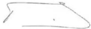
Philippe Vankerkhove
Regulatorni poslovi - direktor za usklaedenost
28/06/2022, Lier - Belgium
POWERPLUS POWEG2010 CS
1 ZAMYSLENEPOUZITI 3
2 POPIS (FIG. A) 3
3 SEZNAM OBSAHU BALENI 4
4 SYMBOLY 4
5 BEZPECNOST 4
6 BEZPECNOSTNI UPOZORNENI TYKAJICI SE ZPETNEHO RAZU6
7 MONTAZ 6
7.1 Montážní nastroje. 7
7.2 Montážni požadavky 7
7.3 Instalace vodici listy / piloveho retezu / krytu spojky 7
7.3.1 Instalace vodici listy 7
7.3.2 Instalace pilového rětezu: 7
7.3.3 Seirzeni naputipilového retézu 8
7.3.4 Seirzeni piloveho retezu: 8
7.3.5 Mechanicky test retezové brzdy 8
7.3.6 Zkouška Řetězové brzdy: 9
8 PALIVO A MAZIVA. 9
8.1 Palivo 9
8.2 Michani paliva 9
8.2.1 Symboly paliv a maziv.. 9
8.2.2 Tabulka palivovych smesí 9
8.2.3 Dopurocenapaliva 10
8.2.4 Mazani retezu a listy 10
9 PROVOZ 10
9.1 Kontroly prd spustenim motoru (obr. 8) 10
9.2 Studeny start motoru 10
9.3 Teply start 10
9.4 Kdyz je motor zaplaven palivem 10
9.5 Zastaveni motoru (obr. 9n) 11
9.6 Provozni test retezové brzdy 11
9.7 Mazani retezu a listy 11
POWERPLUS POWEG2010 CS
9.8 Automatick' olejovaci systém 11
9.8.1 Kaceni 12
9.8.2 Odvětvováni 13
9.8.3 Pferezavani 13
9.8.4 Preezavani na koze 13
10 POKNY PRO UDRZBU 14
10.1 Preventivni udrzbab 14
10.2 Zimni udrzba 14
10.3 Vzduchovy filtr 14
10.4 Palivovy filtr (obr. 17) 15
10.5 Zapalovac svicka 15
11 CISTENIA UDRZBA 16
11.1 Mazání ozubeného kolečka: 16
11.2 Udrzba vodici listy: 16
11.3 Brouseni retezu: 16
11.4 Vodici Iista 17
11.5 Udrzba retezu 18
12 TECHNICKE UDAJE 18
13 HLUK. 19
14 UKLADANI RETEZOVé PILY 19
15 RESENI PROBLEMU 19
16 ZARUKA 20
17 ZIVOTNI PROSTREDI 21
18 PROHLASENIO SHODE 21
POWERPLUS POWEG2010 CS
BENZINOVA RETÉZOVÁ PILA 37.2CC 14" POWEG2010
1 ZAMYŠLENÉ POUžITÍ
Roztec 9.525mm (3/8")
Tlouš'tka 1.27mm (0,05")
Bruste retez v ochrannych rukavicich a pomoci kulatého pilníku o rozméru 5/32" (4 mm).
28/06/2022, Lier - Belgium
POWERPLUS POWEG2010 SK
1 ZAMYSL'ANEPOUZITIE 3
2 POPIS (OBR. A) 3
3 OBSAH BALENIA 4
4 SYMBOLY 4
5 BEZPECNOST 4
6 BEZPECNOSNE OPATRENIA PRI SPATNOM NARAZE. 6
7 MONTAZ 7
7.1 Nastroje na montaz
7.2 Poziadavky na montaz.. 7
7.3 Instalacia vodiacej listy / ret'aze pily / krytu spojky 7
7.3.1 Instalacia vodiacej listy.. 7
7.3.2 Ak chcete nainstalovat'retaz pily: 7
7.3.3 Nastavenie napnutia ret'aze pily.. 8
7.3.4 Ak chcete nastavit' ret'az pily: 8
7.3.5 Mechanicky test brzdy ret'aze.. 8
7.3.6 Ak chcete testovat' brzdu ret'aze: 9
8 PALIVO A MAZANIE 9
8.1 Palivo 9
8.2 Miesanie paliva.. 9
8.2.1 Symboly paliva a mazania 10
8.2.2 Pomer miesania: 40 dielov benzinu k 1 dielu maziva 10
8.2.3 Odporucane paliva: 10
8.2.4 Mazanie ret'aze a listy 10
9 PREVÁDZKA 10
9.1 Kontroly pred startom motora (obr. 8) 10
9.2 Spustenie studeného motora 10
9.3 Teply start 11
9.4 Ked' je motor nasiaknuty palivom 11
9.5 Zastavenie motora (obr. 9n) 11
9.6 Pracovny test brzdy ref'aze 11
9.7 Mazanie ret'aze pily / listy 11
POWERPLUS POWEG2010 SK
9.8 Automatická olejnicka 12
9.9 VseobecnePokyny prerezanie 12
9.9.1 Pilenie stromov 12
9.9.2 Odvetvovanie 13
9.9.3 Rozrezávanie 13
9.9.4 Piflenie s kozou 14
10 POKNY NA UDRZBU 14
10.1 Preventiva udrzba 14
10.2 Udrzba v zime 15
10.3 Vzduchovy filter 15
10.4 Palivovy filter (obr. 17) 15
10.5 Zapalovacia sviecka 16
11 CISTENIE A UDRZBA 16
11.1 Mazanie hrotu ret'azového kolesa: 16
11.2 Udrzba vodiacej listy: 17
11.3 Ostrenie ret'aze: 17
11.4 Vodiaca lista 18
11.5 Udrzba reaze 18
12 TECHNICKE UDAJE 19
13 HLUK. 19
14 SKLADOVANIE RETAZOVEJ PILY 19
15 ODSTRANOVANIE PROBLEMOV 20
16 ZARUKA 21
17 ZIVOTNÉ PROSTREDIE 21
18 VYHLASENIE O ZHODE 22
POWERPLUS POWEG2010 SK
BENZINOVA RETAZOVÁ PÍLA 37,2CC 14” POWEG2010
1 ZAMYSL'ANE POUZITIE
28/06/2022, Lier - Belgium
POWERPLUS POWEG2010 RO
28/06/2022, Lier - Belgium
POWERPLUS POWEG2010 HU
8.2.3 Recommended fuels
28/06/2022, Lier - Belgium
POWERPLUS POWEG2010 RU
1 IcnoJIb3OBAHNE NO HA3HAUYEHNI 3
2 ONICAHNE (PNC.A) 3
3 CODEPJKMOE YNAKOBKN 4
4 YCIOBhIE OBO3HAUHnA 5
5 IPNABUNA TEXHNIK N E3OJACHOCTN 5
6 INPABUNA TEXHNI B3OPACHOCTN, CB83AHHBIE C OTDAUENIJIbI 6
7 CBOPKA 7
7.1 HcmpymeHmbl dna c6opku 7
7.2 Tpe6oBaHua K c6opKe 7
7.3 YcmaHOka nUbHO uHbI /nUbHO uenu /Kpbuku cuenHeu 7
7.3.1 YcTaHOBKa PnIbHOJ uINHbI 8
7.3.2 YcTaHOBKa PnIbHOJ cenn: 8
7.3.3 PerynipobKa HataKeHnI NIIbHoN cenn 8
7.3.4 Perynipobka nnilbnoi cenn: 8
7.3.5 MexaHnuecka npOBepka ueHoro TOpMo3a 9
7.3.6 IpoBepka ceHoro topMo3a: 9
8 TOPIIBO N CMA3KA 10
8.1 Tonnueo 10
8.2 IpuusomoeHue monnuehoCmecu... 10
8.2.1 YcnoBhpie 6o3HaueHnToPnBa n Cma3kn 10
8.2.2 COOTHOSEHNE KOMNOHEHTOB CMEC: 25 yacte 6eH3nHa Ha 1 yactb cma3kn...10
8.2.3 PeKOMeHdyEmbIe BnDbI TOnJIiBa.. 11
8.2.4 Cma3bBaHne cennn nnHbl 11
9 PA6OTA 11
9.1 Ppeynyckoebie npoeepku deuzamena (Puc. 8) 11
9.2 3anyck xolodnoo deuzamena 11
9.3 Topnyu npck 11
9.4 Ko2da deuameIb HacbiueH monnueom 11
9.5 OcmahoeKa dusamena (Puc. 9n) 12
9.6 Ipoeepka pa6ombu ueHnoo mopMo3a 12
9.7 Cma3b1aHue eenu/ wuHbi 12
POWERPLUS POWEG2010 RU
9.8 Cucmema aemomamuuecko0cma3b1aHua 13
9.9 Obue uHcmpykuu no nuJeHuO 13
9.9.1 BaIka IepeBbeB 13
9.9.2 06pe3ka cybeB 14
9.9.3 PackpJxKbKa 14
9.9.4 PackpJxKbKa Ha Ko3Jax 15
10 NHCTPYKUNI NO OBCJYXINBAHIO 15
10.1 Ipoouakmuueckoe o6cnyxueaHue 15
10.2 3umHee o6cnykueaHue.. 16
10.3 Bo3dyuHbI uJbmp 16
10.4 TonnueHbI unbmp(Puc. 17) 16
10.5 Ceeya 3aKuaHua 17
11 17
11.1 Cma3b6aHue 38e3do4ku 17
11.2 06cnyxuehaue nulbhou uunbl 18
11.3 3amouka cenu 18
11.4 PnIbHa uHa.. 19
11.5 06cnyxuehue eenu.. 19
12 TEXHnueCKNE DAHHbIE 20
13 20
14 XPAHEHNE CEENHOI NJIbI 21
15 INAHTHOCTNKA HENCPABHOCTei 22
16 TAPAHTIN 23
17 OKPYXIAOUIA CPEIa 23
18 DEKJIAPAUIN COOTBETCTBn 24
POWERPLUS POWEG2010 RU
ZEHNHA BEH3OПЛА 37,2KyБ. CM - 14"POWEG2010
1 NcNoJIb3OBAHHe NO HA3HAUeHnIO
3TNMOdeJIINpeDHa3HauHeBILJNEHeaCTORIOcNOJB3OBAHnBDOMaUHMENpNHyCaJe6HOM XO3AICTBE DnI TAKNX OblaacteINPImMeHnRAK paCunCTKa 3apocnei KyCTapHnKA,Obpe3Ka BETBeI DepeBBeB,pacnnlNaBaHnE dpOB nT.D. OHn He ppeDHa3HaueHb IINHTEHCBHO 3KcPnyatauIN B TeueHnE dInTeJbHOro BpemEn.H.EcnPiAnHpyeTc INHTEHCBHA 3KcPnyatauIN B TeueHnE dInTeJbHOro BpemEn.To y BnaJeJIbca MOryt BO3HNKHyTb npobLeMbIC KPOBOO6paSeHHEm pyk BCJeDCTBnE Bn6paun. He ppeHa3HaueH dJa KOMMepueckoro NcNoJIb3OBAHnR.

BHUMAHNE!Дя Baewen LInHOn 6e3oNaChOCTN TuaTeNbHO O3HaKOMbTecb c DaHHbIM pyKOBoDcTBOM n 06uMMn yKa3aHNMaN NO TexHnke 6e3oNaChOCTN nepeD Tem, KaN pNcTynITb K pa6ote C MaunHo. PpN nepeDaue 3TOrO 3JNeKtpNueCKOrO HnCTpyMeHTa DnI NOpJB3OBaHNr dpymN IIncaM 06a3aTeNbHO npNJIOXHTe daHbIe INHCTpyKUn.
2 ONICAHNE (PNC.A)
1.Пиьногць
2. NnBnaa
3. Pbyar ceHoro TOpMo3a / 3aunTHbI KOxUx DnpyK
4.передnia рука
5. Puyka cTapepa
6. BbIKIOUaTeJIb OCTaHOBKn DBNtAteJr
7. PpeoXpaHnteBbI pyIar Kypka ra3a
8. 3aHnra pyka /ФнкcaTOp Kypka ra3a
9. KpbuKa MaCnHaRo 6aKa
10. KpbIka TOnJIbHOrO 6aka
LcENb CHN3K0I OTDAUeH nomoraet 3haunTeNbHO CHN3NTb CNJy NHTeHCNBHOCTb OTdauH 6naorapra oc6ooh KOHCTpykUnn OrpaHNUHTeJI rnybHb 3aHHa n 3BeHbeB.
LcENHOI TOPMO3-3To npedoxpaHHTeNbHoe yCTpoiCTBO, KOtOpoe cHnKaet pCK TpaBM n3-3a OTdauN Nnbl, OCTaHaBnBaJ DBNXeHne NnblHOJ CEHN 3a MmllncEHyHdbI. AKTbUpyeTcPbUarOM cENHOro TOPMO3a.
BbIKIOATEJIb OCTAHOBKN DBNATATEJHemeJeHHO octaHaBnBaet DBNATeJIb. IIN BKNIOUeHnI INI NOBTOPHoro 3anycka DBNATeJIb BbIKIOuHaTeJIb OCTAHOBKn DOJXKeH HaxoINTbcR B NIOJXeHn «ON» (BKJI).
PPEOXPAHHTeHbI IN PyIg KYPKA RA3A npedotbpaaet cnyauHoe BKnHueHne DnRaTeJI. KypOK ra3a HeIb3ra HaxaTb npi HeHaXaTOM dKCaTope.
PbIyAR LcENHO TOPMO3A / 3AUHTHBI KOKYX JJI PYK 3aunuaet nebyIO pyky OepaTopa npn COCKaJIb3bIBaHN C npeDHeN pyKn BO BpEmra pa6Oblnbl.
- YIIOBNTJIb LEN yMeHbwaet OnacHocT TpaBM B Cnyae 6pbBa HnCockaKNaHnue NBO BpeMa pa6oTb. YIOBNTJIb CEIN PpeHa3HaueH dJyUaBnBaHn npOBncauOe Nen.

ПРIMEЧАНЕ: OзнakOMьТecь сплои eе DeТаЯМ.
PPEyPPEXJEHNE! PPEyPPEXJEHNE! OTepeaItecb oTdaun. Pn pa6oTe depxnte enhyo nny Kpenko obemmu pykamn. Ira Bauei
POWERPLUS POWEG2010 RU

6e30nacHocTn, npexde Yem nCnoJb3OBaTb ceNHyIO nnIy, npOuHTaTe n npndepxNBaIteCb npaBnI TexHnK 6e30nacHocTn, n3IoXeHHbIX B 3TOM pyKOBOdCTBe. NcNoJb3OBaHne IHCTpyMeHTa He no Ha3HaueHnO MoXeT npNBecTN K cepbe3HbIM TpaBMam.

IPEdYPEXKDEHNE! Pn pa6oTe c 6eH3OHNCTpyMeHTOM Heo6xOIMO co6IIOaTb OCHOBHbIe IpaBnla TexHKn 6e3ONaChOCTN, B TOM YncIe nepeuNCJIeHHbIe HIXKe, dJa CHHXeHn pNcKa NOnyHeHn cepBe3HbIX TpaBM n/INn NOBpeXdEHHN HCtpyMeHTa.
3 CODEPXMOE YNAKOBKN
- YdaJIInTe BCE yNaKOBOUHbIe MaTePnAbI.
- YdaJInte ocTaTkn ynaKOBKn n TpaHCnOpTnpOBOUHbIe KpePHeHn (ecNn OHn eCTb).
- Поверп Te NOЛНOTу KOMПЕКТа NOCTaBKN.
- Поверьтae annapat, сиюов ka6eь, wTencelb n BCE npHaJNeKHOCTn Ha npedmet nobpejdeHn npu TpaHCnpTupOBke.
XpaHnTe ynaKOBOHyBle MaTePnAbI NO BO3MOxHOCTN Do nCTeueHnraHTnHOro cPOKa. Pocne 3TOrO n36aBBTEcB OT Hnx, nCNOJb3yR MeCTHYO CNCTeMy yTnIN3aunn 6bITOBbIX OTXODOB.

BHIMAHHE! YnakoBoHbIe MaTePnaIbI - 3TO He nrgyshK! He no3BolJaTe DeTAM nrpaTb c PnactIKOBbIMn naKeTaM! EcTb onaChocTb ydyuSeHra!
1 ueHna 6eH3oHnla 37,2 Ky6. cm-14"
1pykoBOCTBO NO 3Kcnnyatau
1uénb
1nHbHa uHa
1yexonIJnJIbHOJ uINHbI
1 emKocTb NOc Cma3ky DnA BByXTaKTbIX DBnIaTeJe (nycta)
1 CBEUHOKJIIOU
1 Kpyrbln HannbHnK
1 HeboIbIaIa OTBepTka
2 WeCTnRpAHbIX KIOUa DnI KpenHeHn IINbHOH uHHbl

Ecnn DeTann OTCyTCTByOT nnn noBpeXdHbI, o6paTNTecb K CBOeMy dInepy.
POWERPLUS POWEG2010 RU
4 yCJIOBHBIE O6O3HAUeyHn
B daHOM pyKOBoODCTBe n/nn Ha cAmO MaunHe nCNoJb3yIOc TcJeDyUOuNe CmBOJIbI:
5 INPABUNA TEXHNI B3ONACHOCTN
HE pa6oTaIe c ceHOn nIOI OHO pyKo! Pa6Oa OHO pyKo MoKeT npBecTn K cepbe3HbIM TpaBMAM opeatopa, pa6OuNX IocToPOHHIX NIIc. LcENHa NIIa npedHa3HaueHa dJIra pa6OtBI DByMg pykAm.
HEpa6oTaTe c zenHoi nIIO,ecn Bbl yCTaII,HaxOuNTecb noB BnraHneM HApKOTIKOB,aJKOOrJIyIMMeDINHHCKNXPepapATOB.
HaedeBaIte 3aunTHyIO oSyBb, oIneraiOuIIO OeKdy, 3aunTHbIe nepaTkn n cpeCTBa 3aunTbI 3peHnra, cnYxa n rONOBbl.
Bydte octopokhbl npn o6paueHn c TOnnBOM.Bo n36eXaHne noxapa nepe3anyckom DnurataTey 6eDntecb, YTO CEHNHa HaxoDNTcHa paCCTOAHn He MeHee 3M OT IVHKTA 3apBaKN TOONBOM.
HE no3BOJnTe NOCTOPOHnM JIuam HaxoNTbcra PdOM npn 3anycke nJn pa6oTe c UenHO nnO. He donyckaTe NOCTOPOHnx JIuN JxJBOTbIX B pa6oyu 3ohy.
HE NaHnHaTe pa6Oy 6e3 3aunTHo 06yBn, noka He 6yJeT OCBO6xHeHa pa6OaHa 3oHa Hameyeh IVt b OTXODA OT NadaOpue OpeBa.
- DepxyTe NnIbHyU eHb NpIaJIbSe OT c6e np pa6oTaUuem DnIraTeJe.
-пешд залусом Двигаеля убадиесь, уто пльнаг чьн с чем He coprukacaetc.
- Pn nepeHocke cenHOI nJIbI DBIRATEJIb DOJXeH 6bITb BIKIOueH, NINbHa YINHa I cENb ObaaHeHb Ha3a, a rVWHTeJIb DOJXeH HaxOHTbcra POaJIbIe OT Ta.
HE nCnoB3yIte NOBpeJdeHHyIO, HnPaBnIbHO OTperyNIpOBAHHyIO, HnONHocTbIO NIOHO HeHaDeXHO CO6paHHyIO cENHyIO. Y6eINTEcB, YTO NIIbHra cENb OCTaHaBJIbNAeTcR npi OTNVCKAHNN KypKa r3a.
- PpeKdE Yem NOJOKHTb CEHNHYIO NINy, BbIKIIOUHTe DBNrATeJIb.
БудьтпpeдьнО octopoxHbI npn O6pe3Ke MeNko RyCTapHka mMOJbIX DepeBbeT,Тak KaK ToHKn MaTePnaI MoXe T3actpTaB B cEIN n CTeHyTb Bac NII IN BBIECTN 13 PABHOBecra.
- Pn 06pe3ke HATyHbIX BeTOK n cyuBEB 6yIbTe OCTopoXhbl, NCKOJIbky OHN MOryt OTCKOHTb Pn Ocna6JeHnn HATxJKeHn UVaPNTb Bac.
PyKoRTN DOJXHbI 6bIT cyxHMn. YcCTbIMn H6e3 CJIeIOB MaCJa IIN TOJINBA.
Pa60aTe C HENHOI NIOJ TOJIbKO B XOPOIO IPOBETPnBaEMbIX NOMeueHnX.
HEpaOtaIe C HENHOIIOI NO DEpeBy,ecn Bbl CneHuaJIbHO He OvUaIINCb 3TOMV.
Bce onepaunnoobcnykubahnoucenHno nnilb, NOMMO nepeuNCneHHbIX B daHHOM pVKOBODCTBE,DOJXHBI BbINOJHrTbc KBAJIΦHUPOBAHbIM NEPCOHAOM.
- Ipn TpaHcnpTnpoBKe cenHOI nJIbI nCnoJIb3yIe nOxDxOJaIu YexoI dIa NJIbHOI
HEpa6oTaTe c ceHNoI nnIOB 6n3I neKOBocnIaMeHraUxCJnKoCTe nIra3OB, B NOMEeHNn IIN Ha OTKpbITOM BO3DyXe. 3TO MOKeT pNBEcTN K B3pBiY n/nnn IOkApY.
POWERPLUS POWEG2010 RU
He 3aIbAte ToPnBIO Hn MacNo H He npOn3BOJTe Cma3bBaHne np pa6oTaioeM DBrAtene.
- IcnoIb3yIte IOxOJaHn INCTPYMEHT: NITe TOnbKO DpeBecHy. He nCnoIb3yIte cENHyIO bCeJAx, dN a KOTOpbIX OHa He npedHa3NaYeHa. HApIMep, He nCnoIb3yIte cENHyIO pJIra pa6oTbIC PnactMaccam, KamHeM nn HeCTPOTeJIbHbIMMaTePnaJAm.
Ipejde yem npncTyntb K pa6ote, cJeDyET npoHTn ppaKTnueckn nHCTpykTak C ONbTHbIM ONEpATOpOM NO NcNoJIb3OBAHnIO CEHNHO INJIbI N 3aUNTHoro O6OpyDoBaHnI.
He nbitaTecbdePkaTb cenHyIO nnIy oHoi pyko. Bbl He cmOKeTe KOHTPOINPOBaTb cnny OTdaun n pncKyete NOtepraTb KOHTpoJIb HAD nnIO, YTO MOKET npNBecTN K COCKaJIb3bIBAHIO NNOTCKAKUBAHIO UHHBI NcENIOT CYKA NNCTBONA.
Hikorda He pa6oTaTe c cenHOI nIOB B nOmeeHN. Korda pa6oTaET dBnraTeIb BHyTpeHHeRo CToPAHNA, BbIDeJIaOTc RAIOBtBe BbIXNOnHbIE Ra3bl, KOTOpBE MOrY 6bITb 6ecuBcHTbIMn H He IMeTB 3aJaxa. Pn NcNoB3OBaHN DaHHORo N3dEINr MOrY O6pa3OBbIBaTcB TaJIb, MeKAR MaCLHaH DaCnepChA PbIb N DbIM, CoDEPkaUne BpeHbIe dIpePOdyKTNBbIX fYHKcN XmMueckne CoedHEnHry. He BdixaTe 3TN BpeHbIe BeSeCTBa (TakNe, KaK ONIIKN INN MeJIKyO MaCLNaHyO DnCnepCHyO PbJIb OT CMA3bIBAHN YeN) I 3aUnTIte Ce6r DOJXHBIM O6pa3OM.
Pa6oTaIe B nepaTkax n cJeInte, yTo6bl pyKn 6bln TeNJIbIMn. PpN dIInTeJbHO npa6oTe C cENHO IIOI NOB BO3dEINCTBnEM BN6paun MOKeT pa3BnBaTbcra CnHDPOM 6enbIX naIbueB. Pa6oTa B nepaTkax n KOHTpONb 3a TcNtOToy pK CNHXaOT pNCK pa3BNTnaCnHDPOM 6enbIX naIbueB. PpN NOBHeHN CNMNTOMOB 3TOrO 3aboneBAHnR cpa3y Jx e O6paTntecb K BpaCy.
3aBeNTe 3y6uTbI ynop nINbI npRMO 3a nNaHpyemyU weKy npOnnna n NOBepHnte NNY BOKpyr 3TOI TOCHN. 3y6uTbI ynop HauHET KpyTNbC B CTOPOHV CTBOJa.
ToIbKO cENb, IINHy n CBeCy 3aXnraHnnoJb3ObaTeJIb MoKeT 3aMeHnTb cam. Bcerda nna 3aMeHbI hCNOJb3yIte DeTaII NTO JIe TUNa, YTO yKa3aHbIB TEXHNueCKNX XapAKTEpNCtKAX B DYKOBOIDCTBE NOJb3ObaTeJIa.
6 PABUNA TEXHNI B3OINACHOCTN, CB3AHHBIE C OTDAUENIJIbI
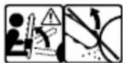
OTDAU MAoKET BO3HKnHyTb npn KacaHn npeDMeTa HOCKOM nH HAKOHEHKNOM NINbHOJ uHHI INn pRn 3aHeMneHN NINbHOJ cENB PPOJIe.
B HeKOTopbIX CnyaX KacaHne IpeMeTa HOCKOM NINbHOI UINHbI MOKET Bbl3BaTb MRHOBeHHVIO OTdauv C bICTpbIM OTCKOKOM NINbHOI UINHbIB CTOPOHV ONepaTOPa.
Pn 3AUEMJHIN nIbHOI cENB DOnb HIXHEI qactn nIbHOI uHHbIOncJeHra MoKet IOTAHyTb NIVy BnepeD ot onepaTopa.
Ipn 3AUCEMJIEN nIbHOJ cenn BdoB BEPXHEJ qactn IINbHOJ uHHbI NOcJIeHJMOKET 6bICTPO OTCKOHTb B CTOPOHV ONepaTopa.
B pe3yIbTaTe IIO6oN 13 3Tnx peakun BBMOXeTe NOTepeTb KOHTPOJb HAD NIIIOH IN OJyUHTb cepbe3HbIE TpaBMbl.
IMe8 OCHOBbIe IpeIcTaBJIeHnO6 OTaue IIbI, Bbl MoKeTe CBeCTN K MHNMy My 3JIeMeHT HeoXuHaHHocTn. HeoXuHaHHocTb YactO CNOCO6CTBVET HeCuaCTbIM CIVyAam
- Pn pa6oTaOeM DnIraTeJe KpeKo DePxHrTe Nnly OBeIMn pyKaMn: npaBoN pyKo 3a3aHIO pUky, a neBcNpyKo 3a npeDnIO pUky. Bce naIbCuI DoJXHbI IIOTHO n HAdExHNO OXBtIBaTb pyKn cENHO Nnbl. 3To NOMOXET UMeHbHTb OTDaCy IN COXPaHNTe KOHTPOB HaI NIOJ. He BbInyCKaIte Nnly n3 PVK.
Y6eNTecb, YTO B pa6oey 30He He TnKakx npenrTcBn. He OnyckaTe KOHTa HOCKa NINbHOI uHbI C 6peBHAM, cybMaN INPOyIMN ppeTCTBnAM, KOTOpbie MOXHO 3aDeTb Pn pa6ote c NINO.
POWERPLUS POWEG2010 RU
-ПиЛNTe Ha BbICOKnX O6OpOTax DBuRatEnIa.
He npehanpraTecb Hn nIte Bbiue ypoBna pIe.
CneDyIte HNCTpyKUmaM N3ROTOBnTeJI NO 3aTOUKe N O6cJyXnBaHnO ZeHNo NIIbI.
- 3aMeHbI NCNoB3yIe TOJbKO UHHbI N cEN, yKa3aHHbIe I3rTOBHTeM, INN INX 3KBIBaJIeHTbl.

ПРИМЕЧАНЕ: Рени Сни КОД OТDAЧЕ - 3TO РENБ, OТBEЧАЮSHAЯ Tpeбованям K ВELNUCHЕ OТDAЧИ.

PPEyIPEXJEHNE: OTdaua cenHO Nnbl MoKET npNBecTN K onacHO notepe KOHTpOJa Hnd HeN i, KaC cIeDCTBHe, K cepBe3HbIM N daJxecMePeJIbHbIM TpaBMam OepaTopa HnN OkpyKaIOuX. ByIbTe BcerDa HaYe. PotaunOHHa JOTdaua N OTdaua npN 3aUeMJeHH YBJIaOTcOCHOBHbIMN BvdaMn ONaCHOCTN npN pa6Ote C cENHO NnLOH N npNUHaMn BoJIbShHCTBa HeCuaCTHBIX CnyaEB.
OcteperaTecb:
PotaunHna OtdaHa (Pnc.1)
A = TpaekTopn oTdaun
B=30Ha peaKuIN OTdaun
ToJyKOBa (OTdau npn 3aueMJeHnn) n TAgobbie peakun (Pnc.2)
A = Targa
B = TbepeIpeMeTbI
C=TONkaHne
7 C6OPKA

PnmuHHe: HxkeOnncAHbIe DeiCTBm MOyT HeCKoJIbKO N3MeHrTbcra B 3aBNCMOCTn OT KynIeHHoM OdeJIn.
7.1 Hcmpymehmbi dna c6opku
IpeynpeKdHHe: He 3anyckaTe DnRaTeJb NNbl, Noka HnCTpyMeHT He 6ydet noNHOCTbIO NOrTOBJeH.
Дя obecneeyHЯ rTOBHOCTH HOBOI cENHOI NJIbI K 3KcNJIyATAUIN noTpe6yeTcR OTperyJInPOBaTb cIb, 3aJIHTb TOnJIHBHyIO CMECb B TOJIINBHyI 6ak I MacNo dIra CMa3Kn cIeIN B MaCJIHbI 6ak.
Ipeed 3Kcnnyataune INJbIOINHOCTBO IPOUHTaTe DaHHepyKOBOcTBO NOJB3OBaTeJI. O6paTnte OC6Oe BHIMAHHe Ha PabUNa TEXHNK6e3OnaCHOCTn.
PyKOBOCTBO NOIb3OBaTeJRABJIeTcN cnpaBOUHnKOM, n pyKOBOCTBOM N 3KCIpyaTuIN, PpeIOCTABJIIOUIM O6uYIO HOpMaUNIO C6OpKe, 3KCIpyaTuIN N 06CNYKBAHNIO INIbl.
7.3 YcmaHOka nunbHou wuHbi / nunbHou cenu / KpbIwku cuenneHu

IpeDynpexKeHHe: npn pa6ote c ceNbIO Bcerda NaedeBaIte 3aunTHbIe nepuATKn.
POWERPLUS POWEG2010 RU
7.3.1 YcTaHOBka NJIbHOH WnHbI
YTo6bHa uHHy n cenb noctynaNo Macno, nCNOJb3yIe ToJIbKO 3aBOIDcKyo uHHy co Cma3OuHbIM OTBepCTnem (A), KAK NOKa3aHO Ha pncyHke Bblwe (Pnc. 3a).
Y6eHTEcb, yTO pbUar cENHO TOpMO3a OTTAYT Ha3aB B NOLOXHe NBE BIKIIOueHnA (Pnc. 3b).
- OTKpyTnTe raiKn KpeJIeHnA uHbI (B). Chmnte KpbIuKy TOpMo3a cen (C), BbTaunB ee npraMO C HeKOTOpBM ycJInem (Pnc, 3c).
- YcTaHOBtTe Na3OBbI KOHeU 5INHbI Ha 6oNT (F). CDbHbTe NnIbHyO 5InHy 3a 6apa6aH MyΦTbI CuENJIeHnR (G) Do ynpa (Pnc. 3d).
7.3.2 YcTaHOBka NnIbHOu cenn:
Pp np a6oTe c cenbIO Bcerda HaneBaIte 3aunTHbIe nepaATKn BBINOJIHnTe peyInpOBKn IIINbHOJ cenn.
PactHnTe cenb B BnDE nTJN, YTo6bl pexyune KpOMKn (1) yka3bIbaN B HappaBHeHHuacOBoCTpeJIKN (Pnc.4a).
- PpOBeIte 1eB BOKpyr 3Be3doKn (B) 3a MyΦToi CcENneHna (C). Y6eIITecb, yTO 3BeHbJ UeN BCTaJI MExyv 3VbJaMn 3Be3doKn (Pnc. 4b).
BCTaBBTe BeDyUne 3BeHbB KahanBky (D) n npoBeDnTe nx BOKpyr KOHca uHHbl (Pnc. 4b).

PpimueaHHe: nIbHa rcenb MoKeT cJeRka npOBuCaTb Ha HxKHe yactn uHHbl. 3To HopMaJIbHo.
CdbnHbTe nIbHyu WnHy Bnepei, noka cenb He 6yDet nIOTHO npneraTb K uHe. Y6eNTecb, yTO BCE BeVUwne 3BeHbJ HaxOJaTcB KaHABKe uHHbl.
- YctaHOBHTe KpbIbKcCueHn, y6eINBbncb, yTO 3y6eU yNopa HaxoNTcB HnXHE MOTBepCTH NIIbHOH WINHb. Y6eINTecb, yTO cENb He COCKAKNBaeT C WINHb. 3aTAHNTe raIKy KpeHnEHN IINHb DO OTKa3a pyKoN i CneDyIte INCTpyKcNmM NO peYnIpOBKe HAraJxHe B pa3dJe «PeynpOBKa HataJxHe NIIbHOu cenN»

Примechанно: на 3Tom 3TaNe raIGN KpeNJIeHnЯ ПИьHoJ WINHbI 3aTЯгИВaIOTc TOnIbKO BpyHyIO, TAK KAK Heo6xOДmAp eryInpOBKa PnIbHOJ cEN. CneDyIte nHCTpyKUmM, npNBeDeHHbIM B pa3dJe «PeryInpOBKa HATJXeHnЯ ПИьHoJ cENN».
7.3.3 Perynupobka HataxeHna NnBHOIeenn
PpabnIbHoe HataKeHne nIbHOJ cENK kpaHe BaxHo I erO Heo6xOIMo npOBepaTb nepeB BKIOUeHem NJIbI, a TAKKE B PPOUCCE NIIeHna.
IpaBnJIbHajpeRyIIpOBKa nIbHOJ cENI npBedeT K NOBbIeHNIO npOn3BOaNTeJIbHOCTN IINHeHnI npOdJIeHNIO cPoka cnjx6bl cenn.

PpeynpeKdHne: Pn pa6ote c nnIbHOI cenbIO Bcerda HadeBaTe 3aunTHbIe nepaTkn N BblONHJrTe peryNIpOBKn cenn.
7.3.4 PerynpoBka nIbHOn ueN:
- UTo6bI yBEnHHTb HATJKeHne cEN, NOBepHnTe perynipoBOHyb BnHT (16) no YacOBoCTpeNke, HAnpabNB HOCOK nnbHO hnBb BBepx. UTo6bIOcna6ntb HATJKeHne cEN, NOBepHnTe perynipoBOuHb BNHT npOTnb YACOBO CTpeNKn. Y6eNTecb, YTO cENb PLOTHO CNDHT Ha nnbHO uHe No BcE ee DInHe. (Pnc. 5)
POWERPLUS POWEG2010 RU
Iocne BbIOJIHeHnpeRyINpOBKn HaTaeHnna, npOIOJXKa ydePKNBaTb HOCOK uHHbIB KpaHem BepxHem NIOJKeHN, PNOTHo 3aTAHnte RaIKN KpeJIeHnua Hnbl. CHTaETcnpABNJbHO 3aTAYTOE, eCNI OHa IIOTHO oBJIeAet WInHy NO BceN ee DInHe m MoKet IOBOPaUNBaTbcr pykoJ.

Примочанe:Есицentурдно nobephyт ha пьhoишпо Ип оha 3actppeBaet,Занчт OHa habrayta cnilskom cnlbHo.В зTom слуаe Tpe6yETc spledyucaЯ Heboьшя perynipobka:
Ocna6bTe raikn KpeJIeHn IINhbl, YTO6bl OOn OTKpyuBaIncB BpyHyIO. Ocna6bTe HataJxHe nEi, MeIeHNO NOBepHyB peryInpOBoHbI BNHT IINhbl IpOTNB YacOBoi CTpeIKN. NOpBraIte cenb no IINHe BnpePd-Ha3aI. PpOdoJIkaIte peryIpOBky Do Tex nop, Noka ceNb He 6ydt CBO6OdHO nepMeUaTbcr No IINHe, DOCTaTOHNo IIOtHO o6nera ee. YBeJIuYbTe hataJxHe, NOBepHyB peryIpOBoHbI BNHT IO YacOBoi CTpeJIke.
Iocne doctnxkeHn HaJnxkaeero HataxkeHn NJIbHOI cENI NIOHTHO 3aTHNTE DBe raKn KpenHeHn WInHb, ydepXNBaHOCOK WInHb B KpaHem BepxHem NOLOKeHHN.

BHHMaHHe: HOBaIeNBpactaRnBaETc, Tpe6y peryNIpOBKn HaTaeHNe Ype3 5 nJIeHn. 3To HopMaJIbHO dJIra HOBoI cENn, HO BnOcJIeDCTBn INHTepBaJ MExdy peryNIpOBkAm6 bIcTpO BblpactTe.

BHHMaHHe: ecn nIbHa r cenb HaTMyTa CnHsKOM cna6o nnCnHsKOM cnIbHo, To 3Be3doUka, uHa, cenb N noDunNnKn KOJeHuTaTO RaBa 6ydyr n3HaunBaTbcra 6bictpee. Ha Pnc. 6 nokaaho npabnIbHoe xOIoHoe HaTJXeHne (A), nporpeToe HataKeHne (B) n cnyaai, kOrda Tpe6Byetcra NoTJA KnIbHOu cenn (C).
7.3.5 MexaHueckaj npOBepka cenHoro TopMo3a
Ba7a ceHna nHa oChaueHa cHbIM TOpMO3OM, CHXaUoIm pNCK NOyueHn TpaBM n3-3a OTdauH nIbI. TopMo3 BkJIouaetc npi DaBLeHn Ha pbUar TOpMo3a, KOrda pyKa OepaTopa UdpAerT no pbUary, KaK 3TO npOxCxOanT npn OTDaue nIbI. PpN BKJIOueHn TOpMo3a DBHXeHne cEN MrHOBeHHo NpeKpaUaeTcR.

PpeDynpexDeHne: cENHOI TOPMO3 cnyKNT dJIa CHNXeHn PnCKa TpaBM n3- 3a OTdauN pINbI; Ondako, OH He oBeCneuT DOJXHyO CTeneHb 3aunTbI npn HecOtopoXHo pa6ote c nnloN. PepeB BKIOUeHnem NInbI INepnoDnueckn BO BpeM pa60tbl npOBepaTe cENHOI TOPMO3.
7.3.6 ПоберkaценHoroTopMo3a:
- LcENHOI TOPMO3 BbIKIOUeH (cENb MOKeT DBNrA TbCB), KOrDa pbYar TOPMO3a OTTH Ha3aI N 3a6JIOKIpOBaH. Y6eIITecb, YTO fIKCaTOP cENHOrO TOpMO3a HaxoDNTcB I NOIOXeHN BBIKIOUeHn (Pnc.7a).
- LcENHOI TOPMO3 BKNIOUeH (cENb He DBNrAeTc), KOrJa PbIur TOpMO3a HAXOINTCB INpeDHeM NIOJOKeHn, INΦIKCaTOP cENHOrTO TOPMO3a HAXOINTCB NIOJOKeHn BKNIOUeHn. B 3tOM Cnyae cENb He DoJXHa DBNrATbcra (Pnc. 7b).
POWERPLUS POWEG2010 RU

IpimMeuHHe: pbyar TopMo3a DoJxKeH IerKo BXOAnTb B O6a NonoXeHn. He pa6oTaIte C nIoNo, ecN Bbl OuyuaTe cInbHoe cOnpOTnBLeHne, nIeCn pyiHar He nepemEuaTeCBAODHO nONoXeHn. Cpa3y Xe OTBe3nte nnNy B npocceCnoHaJIbHbIM cepBnCHbIM ueHTp dJa peMOHTa

He donyckaTe pa6Ory dBnraTeJHa BBICOKo CKOpocTn, KOrda BkIIOueH cenHOr TopMo3.
8 TOPIIIBO N CMA3KA
8.1 Tonnueo
Дя NOЛуеня Hanluywhx pe3yIbTaTOB nCNoJIb3yIte He3TNIpOBAHbI 6eH3IN CTaHdapTHoro KaueCTBa CO CneUaJIbHbIM MOTOPbIM MacIOM IЯ DBYXTaKTbIX DBrIaTeJIe IN COOTHOseHnEM KOMnoHErTOB B Cmecn 40:1. Cm. nponopuim CmeuBaHnB B pa3deJe «TaNua TOnIIIBhIx Cmecn» HIXe.

IpeDynpexKeHHe HNKOrda He npImeHnTe B Nnle 6eH3nB YnCTOM Bnde. 3To npNBedeT K NOlOMKe DnRatelaN n PpeKpaSeHHIO DeiCTBnra rapaHTn N3ROTOBNTeHa 3To N3dJIne. He nCNoJb3yIte TOnJIbHyIO Cmecb, KOtopar XpaHnacb 6OJee 90 dHe.

IpeynpejdeHne: B KaecTBe Cma3Kn Dnla DByXTaKTHbIX DBNrataTeNe cJeYeT NcNoJIb3OBAb MacNo BbcJero CopTa Dnla DByXTaKTHbIX DBNrataTeNe BO3DyUHoro OXnaXdEHHN Prn COOTHOseHHN KOMNOHEHTOB Cmecn 40:1. He nCnoJIb3yIte dpyRne MacJa Dnla DByXTaKTHbIX DBNrataTeNe C peKOMeHdyEmbIM COOTHOseHHem KOMNOHETOB Cmecn 100:1. Ecnn npuHnOH NOBpejdeHnraDBnraTeJI OKaKeTcH HeIOCTaTOUHa Cma3Ka, 3To aHHynpyeT rapaHTNU H3ROTOBtEn Ha DBnraTeNb.
8.2 PpuzomoeHue monJueHoCmecu
CmeaIte TOnnBO C MacJOM B noXoJaSeI eMKocTb. B36oJTaIe eMKocTb, yTo6bl oecneuHb XopoOee cMeunBaHne.

PpeDynpexKeHHe: HeoctaToK cMa3Kn ppeKpaAaet DeiCTBne rapaHTn Ha dBnraTeIb. BeH3nC MacJOM DoJIxHbI CMeuNBaTbcR B COOTHOWeHn 40:1
8.2.1 YcnoBhie 06o3HaueHn TaJIInBa n Cma3Kn

8.2.2 COOTHOJHeHne KOMIOHeHTOB Cmecn: 25 yacte H6H3nHa Ha 1 yactb Cma3Ku
9.1 IpeynycboI npoeepku deuzameJ (Puc. 8)

PNEyIPEXDEHNE: HnkOrda He BkIouaTe Nnly, ecn He ycTaHOBJIeHbI npabNbHO uHa n cenb.
3aneTe B TOJIINBHyb6ak (A) npaBnIbHO npriROTOBHeHHyTO TOnJIINBHyO CMEcb.
3aneTe B macJHbI 6ak (B) cMa3ky dJIe IeHHu HxKHO Tnna.
9.2 3anyck xonodhozo deueamej
- AkTNBnpyuTe cENHOI TopMO3 (cDINbTe 3aUNTHbI KOxUx IJI pyK BnepeN 3aΦNKCuPyuTe erO) (Pnc, 9a).
- 3aynycka nIbI nepeBeDnte BbIKIOuATEnb (BKJI/BbIKI) B noIOxHne «ON» (I) (Pnc.9b).
- ПовернITE рыаг ВОЗдунов Заснон (A)В полжени erо Фик caln (Pnc. 9c).
- IonoJte nIy Ha npOHyIO pOBHyIO NOBepXHocTb. KpenKO depKInTe nIy, kak noka3aHO ha pucynke. HeckoIbKO pa3 pe3KO depHInTe 3a pyuKy cTapTepa, noka He ycblIuNTe nepBbIe 3Bykn 3anycka Dnuratena (Pnc. 9d).
Bo3dyuHa 3acNoHka aBToMaTuYeCKn 3akpoETc npn HaxaTn Ha nepeKluOaTeNb DPOCCeNBHO 3acNOHKn. (Pnc.9e). - Pe3ko DepeHnTe Tpoc cTapTepa, noka He 3anyctntcra DnRaTeNb. (Pnc. 9f)
Cnerka Haxmnte Ha nepeKIOaTeJb IPOccelbHoi 3acNoHKn (Pnc. 9q).
OTBeDHTe Ha3aad pbUar TOPMo3a, UTo6bI OTNcTnTB cENHOJ TOPMo3 (Pnc. 9h).
9.3 Fopauu nyck
- AKTUNBUPyIe CEHNoT TOPMo3 (Pnc. 9i).
- YctaHOBInTe BbIKIOuHaTeJIb (BKn/BbIKn) B noIOXeHne «ON» (I) (Pnc. 9j).
Pe3ko DePHHTe TPOC CTAPTePa, NOKa He 3anyCTNTc yBnTaTeJb (Pnc. 9k).
Cnerka Haxmnte Ha nepeKIOuateJIb dpoceIbHO 3acNOHN (Pnc.91).
OTnycntte enHOn TopMo3 (Pnc. 9m).
9.4 Kozda deusamelhacbiueH monluueom
CHIMnTe BO3DvHbIΦnIbTp.
BbIKpyTnTe CBeV 3aXnTaHn
PacnoJoxKte NIVy NOI yJOM 45° cIbB BBepx
Heckonbko pa3 DepeHnTe Tpoc CTapTepa
OuHCTNTe CBeUy 3aXnIraHnY uCTaHOBInTe Ha MeCTo
YCTaHOBtE Ha MeTO BO3dyuHbI ΦnJIbTp IN BblIOJIHInTe 3aNyCK 6e3 NcNOJb3OBaHIN BO3dyuH0N 3aCNOHKn
POWERPLUS POWEG2010 RU
9.5 OcmahoeKa deusamei (Puc. 9n)
-
OToXMMTe IpeDoXpaHHTeIbHbI nepeKIOUaTeJIb I daIte DBrAteIIO nopA6OtaTb Ha XoTOCTOM XOIV.
-
IpebeEnTe BbIKHouaTeIb I/O (BKn/BbIKn) B noJoxeHne «O» (BbIKn) nla octaHOBKn DBNrataTeJI.

ПриMueаннe:ДЯЗКТpeHNoOcTaHOBKnпpoCToakTbHpyYeTeцEHOn TopMo3ипepeBeДnteБblKlIouaTeNbI/O(BkN/BblKn))ВпоLoxeHne «O» (BblKn).
9.6 Pnoeepka pa6ombl eHNO2 mOpMo3a
IepnoDnueckn npOBepRte pa60tococ6Hoctb ceHoro TOpMO3a.
BbInonHnIte npOBepky cENHOro TOpMo3a neped nepBOHaayabHbIM nIIeHNHeM, nocJe DInTeNbHO INJIeHnN I O63aTeNbHO NocJcO6cNyKbAHnA cENHOro TOpMo3a.
PpOBepka ueHoro TOpMO3a Ipon3BODITcCJeDyUOUM 6pa3OM:
- IIOJXHTe NINy Ha YNCTYIO, INPOUYIO IN POBHYIO NOBEPXHOCTb.
3anyCTnte DBNrTaTeJIb.
Bo3bMNTecb npaBOy pYKO 3a 3aHIO pUky (A) (Pnc. 10).
- Jebo pyko kpenko depxntecb 3a nepeHIOpyky (B) [He 3a pbuvar zenHoro TOpMo3a (C)] (Pnc.10).
HaXMMTe Ha KypOK ra3a Ha 1/3 xOJa, 3aTeM cpa3y Jx e AKTNBUPyIe pbUar LcENHOro TOpMo3a (C) (Pnc. 10).

IpeDynpexdHHe:akTNBpyTe cenHOJ TopMO3 MeJneHHO,He CneHa. CJeHTE,TO6bI cENb He KacaJacb HnKaKnx IpeMeTOB; He DonyckaTe HaKIOHa cenn Bnepd.
LcenbdoJnxHa pe3ko octaHOBntbc.Korda OHa oCTaHOBNTc, cpa3y Jx OTnycTne nepeKIOUaTeIb DpOCCeJIbHOJ 3acNOHKn.

IpeDynpexKeHHe:ecnUcENbHeOCTaHaBJIuBaETcR, BbIKIOUHTe DBuratEnb NOTBe3NTe Nny B 6nXaMn ABTOpN3OBaHHbI CepBnCHbI cEHTp dnn O6CnyXuBAHn.
- Ecnn cenHoi TOpMo3 pa6oTaET HopMaIbHO, BbIKNIOHTe DnBraTeNb I BepHIne cenHoi TOpMo3 B NOJIOKeHne BbIKNIOUeHn.
9.7 Cma3b1aHue eenu / wuHbI
DcTOHcMa3bHaHne NJIbHOI cENI BO Bpempa60tI Heo6XoIMO dIaMHm3aun TpeHnO pNlHyU uHy. He donyckaiTe 3KcnlyatauHIO nINbIC HeoCTaTOHbIM KOInueCTBOM Macna.Pa60ta nIbI 6e3 Macna IIN C HeoCTaTOHbIM ERO KOInueCTBOM yMeHBsIT 3ΦΦeKTHBHOCT b INJeHn, COKPATCpOK Cnyk6bl INbl, Bbl3OBET 6bICTpoe 3aTyPHeHne cENI uPe3MepHbI IN3HOC uINHbI IN3-3a nepepeBa. HeoCTaTOHoe KOInueCTBO Macna ONpeDeJareTcno DbIMy, IN3MeHeHHIO CBeta uINHbI INN O6pa3OBAHIO CMOnbl.

Примочанe:В поцecce Испльзовая сени радгимаетс,ocobehno Kordа она HOBAЯ,N Врем OT Врemeи ee Heo6xodmo perynipoBaTb NODTARBaTb.Hobyu cenb Heo6xodmo perynipoBaTb пimepho uepe3 5 MNHyr pa60tbl.
POWERPLUS POWEG2010 RU
9.8 Cucmema aemomamuueckozo cma3bieaHua
BaSha cENHnA nHa nMeET CnCTemy aBToMaTnueckoro ynpaBJIeHnCm3bIBaHnEM. OHa aBToMaTnueckn IOnaet HuxHoe KOnuYeCTBO Macna Ha ShInHy nIeNB. PpN NOBbIWeHN oBOpOTOB DBrIraTeNa YBeINuHBaETcN OdaCy MaCna Ha ShInHy.

He BbINOJIHnIte peryJInpOBky cncTeMbI cMa3bIBaHnI cenn, noka He BbIKJIIOUeH dBnraTeJIb.
CnCTema cMa3bIbAHn IeHn HAcTpoEHa Ha 3aBoJe Ha CpeHIO IOaUy MaCna. Ppn Heo6xOJIMOCtN, NOdaCy MoXHO peryJInpOBaTB.
-ДяperулрOBKnoDAuMaMACna NOBepHnTe peRyIpoBOOHyBn BnHT Ha HnXHeY qactN Kopnyca (19) (Pnc. 11)
- Pn noBopTe BnHTa no YacBOB cTpeJIke NoJaCaMa MacJa yMeHbJaaETcra, a npn noBopoTe npOTnB YacBOB cTpeJIkn - yBeJIuHbAeTcra.
9.9 Obuue uHcmpykuuu no nuneHuO
9.9.1 Banka DepeBbeB
Banka depebbeB - 3TO TepMNH, o6o3hauoui CNnINBaHne depeBa. He6oJIbUne depeBBa co CTBoIamN 15 - 18 CM B DnAmTepe O6bHuO CNnINBaIOCTc 3a OOnH npoxoJ. BoJeE KpyHbIe depeBbA Tpe6yIOT HeCKoJIbKnx 3aIIIOB. 3aIINbI ONpeDeJIaOT HAnpaBHeHne naDEHnA cnIIIBaEMoro depeBa.
CnunBaHne depeBa:

PpeDynpexJeHHe: nepeCnHnBaHem DepeBa CneDeyET npOdyMaTb n, npH Heo6xOaMocTn, pacuNCTntb NytB OTxOda (A). NytB OTxOda DoJKeH nIaTn Ha3a# NO dHaRoHaHn OT OXnDaEmoN LInHn NaDeHn DaPeBa, KaK NOKa3aHo Ha Pnc. 12a

BHHMaHHe: npn cnHnBaHnn DepeBa Ha cKNoHe onepaTOp cenHoN nnblI dOJIKeH cTOrTb BblIe No cKNoHy, TaK KaK cnHJeHHoe DepeBO MoXeT NOKaTHTbcra Hnn cbExaTb BHn3 nO cKNoHy.

PpimMeaHne: HapabJeHne naeHnB (B) onpeDenraTc 3annom. Ipeed BblnoJIHeHem 3aIIIOB yHTnte pacNoIoxKeHne 6OJee KpyNbIX BetBei n eCTeCTBeHHbI HaKIOH DepeBa, YTO6bl ONpeDenNTb HApabJeHne naeHnA.

PpeDynpexDeHne: He cNJIbAte DepeBO npn CnIbHOM nIe MeHraUoEMcB BeTpe nn pncke NOBpeDntb NMyuEcTBo. PpOKOHcyIbTnpyTeCb CnpOpeccnoHaJom. He cNJIbAte DepeBO, ecn cyuecTByet pncK IOBpeXdHn IPOBODoB; corlacyTe cNIIbBaHne C KOMMyHaJIbHbIMN cnYk6amn.
O6nne npabuJa BaJKn DepeBBeB:
O6bIyHO cINIIIBaHne DepeBa BkIIOuaET B ce6raBbe OCHOBHbE ONEpaunn: 3aINbI (C) n BbINOJIHeHne OCHOBHOro npOnnna (D). Chayana cdeNaite BepxHn 3aNl (C) Ha cToPoHe naDeHnA DepeBa (E). 3aTeM cdeJaTe HIXHn 3aNl, pni 3TOM OH He DOJXeH 6bITb CNIuKOM rIy6OKIM.
3aann (C)doJxeh 6bItb DOCTaTOHNO rIy6OKM dIra CO3aHnA WeyKn (F)doCTaTOHn HINHBn I npOCHOTn. 3aann doJxeh 6bItb DOCTaTOH NO WInPOKm, YTO6bl MOXHO 6blno HAnpaBnTb NaDeHne DepeBa KaK MOXHO daJIbWe.
POWERPLUS POWEG2010 RU

ПЕДУПЕЖDEHNE: He XODHTe Hc STOHTe NpeD DepeBOM, Ha KOTOPOM cdeNaHbI 3aHnbl. CdeNaTte OCHOBHO npOnn (D) c npOTNBONIOJXHO CTOpOHbI CTBOHa n Ha 3 - 5 cm Bblse Kpaar 3aHnla (C) (Pnc. 12b)
HnkOrda He npOnnInBaIte CTBOJ HACKBO3b. Bcerda ocTabnIe ste Ky. WeiKa HappaBnreT DepeBO. Ecn n npOnnInTb CTBOJ HACKBO3b, Bbl nepeCTaHeTe KOHTpOJInpOBaTb HAppaBJIeHne NaDeHn.
3apahee, noka depeBO He NOTepReT yCTOuHBOcTB H He NaHT BCTaBbTe B npOnnJI KInn nn pbUar. 3TO ppeoTbpaTNT n3r6 nnbHO uINbI B npOnnIe, eCn Bbl Oun6BeTcB HAnpabNeHN naDeHn. PpeJe Yem nobaHT depeBO, y6eINTecB, YTO B 30He naDeHn HNKOro Het.

IpeDynpexDeHne: npexde yem OKOHaTeJbHO cNJIHTb DepeBO, eue pa3 npOBepbTe, HeT JN B OnachO 3OHe NOCTOPOHHX JNU, XNBOTbIX NJI npenTCTBn.
OCHOBHON npoJI:
-
Историяе Depebraхы e nii nactMaccobbie KlnHBa (A) Дя пedingТрашени нзriба shinb i nii zueni (B) в пошп. КlnHBa takke koHTpoNpyIOT naDEHne DepeBa (Pnc. 12c).
-
Ecnn DnAmetp cnNnnaemoro depeBa 6oJbwe dInHbI uHHbI, To cdeJaTe Dba npOnnla, KaK noka3aHo (Pnc. 12d).

ПЕДУПЕЖDEHNE: Пи пиблжсен OCHOВНО npoина K weKe DepeBOdoJxHo Naatb. Korda DepeBO NaHTaTb, BbITaUNTe NnIy n3 npoINJa, BbIKNIOUHTe DBnraTeJIb, NOJoxNTe NnIy n NOKnHbTe 3OHy no 3apaHee HameeHHOMy ny (Pnc. 12a).
9.9.2 O6pe3ka cybeB
06pe3ka cybeB - 3TO npocecc ydaeneHc noBaeneHHoro DepeBa BetBei np. He OTnJIbAitTe IopdepxNBAIOUne cybJdo Tex nop, noka CTBOJ He 6ydt paCNIJIeH Ha YaactN (Pnc. 13).
HaTarytble BcKn CneJeYOTnnuNbAtb CHN3y BBepx Bo n36eXaHne 3aueMneHnna NJIbl.

EcnBaSha cenHnA nHa Tpe6yET 3mHero o6cnyKbAHn - NO BOpocam TaKOrO o6cnyKbAHn O6paTntecb K BaWeMy MeCTHomy dInIepy.
3To 06cnykmbaHne BkIIOuAeT B c6b cNeyUOuNe onepauN:
-3aMeHa CBeu 3axnraHn.
-3aTOUka Ueenn
- OYNCKa BO3dUshoro fNJIbTpTa (3aMeHa, npn Heo6xOuMoCTn)
OuNCTKa NINbHOH UHHbI
- npoBepka MacnHoro Hacoca
TtataTeJIbHaOuNCTKa
TOUHa HaCTpoiKa HnpOBepKa B pa6Ote
10.3 Bo3dyuHbI uJbmp

BHHMaHHe: HNKOrda He pa6oTaIe c nHNoi 6e3 Bo3DyUHoro fNtpa.
TbInb i rpa3b nonaMyT B Dnuratelb N NOBpeJr erO.CJeIte 3a uHcToToB
BO3DyUHoro fNtpa!
OuHCTKa BO3dUshHO φnIbTpɑ:
- CHIMNTE pyky (A), Φικυργιουγι Κρβιχ ky BO3dUHOrO ΦιNbTpa, CHIMNTE BερxHIOKpbiuKy (B), oTKpyTNB cTOnOpHbI BnHT KpbiUKN. KpbiUka 6yndeT ChraT (Pnc. 16a).
- 13BnKeNTe BO3DyHbI ΦnBtp n3 Kopnyca (Pnc. 16b).
- PpOdyTe BO3dUHbI ΦnIbTp CxKaTbIM BO3dYXOM. PpN CnJIbHOM 3aRpa3HeHN IpomOnTe ΦnIbTp B YnCTOM, TeplOM pactBOpe MblbHOBdI. PpONoNcKaTe B YnCTOxOJHOHOBe. POnHOCTbIO npocuHTe FnIbTp.

HE INCIOJIb3yIte HNKAKNX DpynX IHCTPymeHTOB.
- PpOBePbTe MeK3eNKeTPOHbI 3a3Op c NOMoUbIO pPoBOIoUHOrO KaIbpa I, npn Heo6XoDmOCTn, yCTaHOBnte 3a3Op Ha 0.025" (0.635 MM).
- YCTAHOBITE HOBYU CBEUY 3aXnraHna.

12 TEXHnueCKNE DAHHbIE
3NaeHn yPbNHa, n3MepeHHbce cornaCHO COOTBeTCTBHyOcEmy cTaHdApTy (K=3)
YpOBeHb 3BykoBOrO daBJeHnla LpA 97 dE(A)
UpoBHeB 3ByKOBMOuHocTn LwA 110 d6(A)

BHIMAHHE! YpOBeHb 3ByKOBOrO daBHeHnMa MoKeT npEbIaTaB 85 d6(A). B 3tOM clyuae Heo6xOdmo nCNoJIb3OBaTb INHdNbDyalbHbIe cpeIcTBa 3aunTbI opraHOB clyxa.
aw(Bn6paun):
5.0 m/c²
K=1,5M/c²
POWERPLUS POWEG2010 RU
14 XPAHEHNE UENHOI NJIbyI
BHHMaHHe: HIKoRda He XpaHInTe cenHyIO NnIy DoJIbSe 30 DHe 6e3 npOBeHnra CneDyUOxN onepaun. Ipeed pa3MeueHem ueHOn Ha xpaHHe nIteNbHocTbIO 6OJe 30 dHe HEO6xoJIMo npOBecTu KOHCepBaunIO. Pn HEC6IHOeHN nPabUN XpaHHeN OCTaBWeecr B KAp6Hpatope TOnnBO 6ydt NcnapAByc, OCTaBnAR CMONOO6pa3HbE OTIOXeHn. 3TO MOKeT npIBeCTu K TpydHOCTAM pRn 3aNyCke IN K DOPOROCTOaemy peMOHTy.
MeHnHO CHMnTE KpbIuKy TOnJIbHOrO 6aka, YTo6bl c6pocntb daBHeHne B 6ake. OctopoxHo CJIeTc TOnJIbBO n3 6aka.
3anyctnte DnBiratelb N daTe emy Bbpa6oTaTb TOnJIbBO, octabweecB Kap6IopaTope.
-ДаиTe DBURAteIIO OCTbITb (npn6I.5 MmHyT).
C NOMOJIIO CBEHORO KIIIOUa CHIMITE CBEUY 3AXINaHnI.
3aene Te B kamepy cropania Ondy yauHy IOxky uCToro Macna dny DbyXTaKTHOro dBnataTeI. HeckoIbko pa3 MeJneHNO notAHnte 3a whyp cTapTepa, YTO6bl NOKpbITb MacnOM BHTpeHHne Detajn. UcTaHOBnTE Ha MeCTo CBeuy 3axnraHnra (Pnc.24).

Приимechанee:хранite пилв BCyXOM MeCTe BdaJIH OT NCTOCHNKOB ORHЯ,ТaknxΚak Neu, ra3OBbIe KOJOhKn, ra3OBbIe cyuINKN I T.D.
PacOHcepBaIy IocIe xpaHEnIa
BbikpyTe CBevy 3aXnIraHna.
Pe3ko NotraHnte uHyp cTapTepa, UTO6bI ydaJIHTb OCTaTK MaCJa N3 KaMEpbI CROpaHnA.
OuHCTHe n npOBepbTe 3a3Op B CBeue 3axnraHn yIy cTaHOBIne HOByIO CBeuy 3axnraHn C Tpe6vEmbIM NCKPOBbIM NPOMEXYTKOM.
- PnOtroTOBbTe NIVy K paBoTe.
3aneTe B TOJIINBHyI 6aK TOJIINBHO-MacJryo Cmecb. CM. pa3JeI «ToJIINBO n Cma3Ka>.
15 DnAΓHOCTNKA HENCINPABHOCTEI
HnKeNoDnncabuNc daeCTbyeT OT nMeH NcNoNHTeNbHO dIpeKTopa KOMnaHIn,
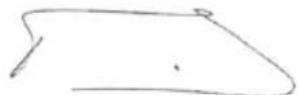
Philippe Vankerkhove (Фильп Ванkeрховe)
OTdHn HopMOKoHTpOJa -MeHeJxep no Bonpocam cornaobAHm
28/06/2022, Lier - Belgium
POWERPLUS POWEG2010 BG
1 IPEdHA3HauEHNHe HA yIOTPEbATA. 3
2 ONICAHNE (FIG A) 3
3 CnncbK HA CbIbPjAHNETO HA NAKETA. 4
4 CnMBOJIH 4
5 INHCTPYKcIM 3A BE3OpACHOCT. 5
6 IPEIa3Hn MEPKN CPEUy OTCKAuaHETO. 6
7 MOHTAX 7
7.1 MoHmaxHu uHcmpymemu.. 7
7.2 3uckeaHua 3a MoHmaKa 7
7.3 NocmaeHa HnpaBnaa/epuHa /mpuHa /kanKaHa cbeDuHumei
7.3.1 3a da noctabnte hnpabnaata uHa
7.3.2 3aДаMOHTIpaTeBepnKHHaTPOH: 8
7.3.3 PerynnpaHe Ha onbHa Ha Bepurata Ha TpnoHa.. 8
7.3.4 3a da peryunpaTe Bepurata Ha TpnoHa: 8
7.3.5 MexaHnUHO n3nTahHe Ha BepnxHaTa cnnpaKa 9
7.3.6 3a da ce TectBa BepnKHaTa cnnpaKa: 9
8 TOpNBO N CMA3BAHE 10
8.1 TOpueo 10
8.2 Cmeceha He Ha 20pu6o 10
8.2.1 CnMBoJIa roPnBO n Cma3BaHe 10
8.2.2 TaBnua 3a cmeBaHe Ha roPBO 10
8.2.3 IpropbUbaHn rOpBa 10
8.2.4 Cma3BaHe Ha Bepurata N uHHata 11
9 ΦУнкцИОнчИРАЕ... 11
9.1 Ipeocmapmou npoeepku Ha deuzamea (Fus 8) 11
9.2 CmydeH cmapm 11
9.3 TonbI cmapm 11
9.4 Kozamo deuzamern e Hacumc c zoupo 11
9.5 Pecmapupahe Ha monbl deusamen 11
9.6 3a da cnpe deusamennm (phi. 9e) 12
9.7 ΦyHKuOHaJIeH mecH Ha eepxHama cnupaKa 12
POWERPLUS POWEG2010 BG
9.8 Cma3eaHe Ha eepuzama Ha mpuoha / wuhama 12
9.9 AemomamuHa MacIbOHka 13
9.10 06u uHcmpykuu 3a p3ane 13
9.10.1 10BaJIaHe 13
9.10.2 KacrtpeHe Ha KIOHn 14
9.10.3 Pa3rpynBaHe 14
9.10.4 Pa3tpynBaHe c n3noJ3BaHe Ha Marape 15
10 INHCTPYKUN 3A NOIDPbXKA 15
10.1 IpoΦunakmuHa nooepbXka 15
10.2 3umHa nooepbXka 16
10.3 Bb3dyueen fummbp. 16
10.4 Филmbp 3a eopueo (Фue.17) 16
10.5 3anaumenha ceeu.. 17
11 IOUHCTBAHE I NOIDPbJKA 17
11.1 Cma3eaHe Ha pexeuzama yacm Ha cepuxkHOMo 3b6Ho KOJIeNo: 17
11.2 Nodopbka Ha Hanpaenreaaama wuHa: 18
11.3 HamoyeaHa eepuzama: 18
11.4 HapraeJea 7uHa 19
11.5 Nodobpkahe Ha eepuaama 20
12 TEXHnueCKn DAHHN 20
13 21
14 CbXPAHRAHE HA BEPIXEHTPOOH 21
15 HAMIPAHE N OTCTPAHRAHE HA HEN3INPABHOCTN.....22
16 TAPAHU 23
17 OKOJIHACPEDA 23
18 DEKJIAPAUJ3ACbOTBETCTBNE 24
POWERPLUS POWEG2010 BG
BEH3INHOB BEPUNKEH TPNOH 37.2CC 350MMPOWEG2010
1 ПЕДHA3HAUECHNE HA YNOTPEБATA
Te3n MoedeJI Na npedHa3HaueHn 3a He MHoro YecTo H3NoJ3BaHe OT CO6CTBeHnHa KbI, BnI, NocETeJI Ha KbMnIHn n 3a O6uN cEJI, KaTO ceUHe, OkactpRHe, Pra3aHe Ha DbPba 3a ropeHe n T.H.
Te He ca npedHa3NaeHn 3a npoBjXkntHa ynoTpe6a. Ako ynoTpe6ata n3ncKba npoBjXkntHa pa6ota, Bn6paunte Morat da IOBeaT do npo6neMn B KpbBo06paueHneTo Ha pueTe Ha noTpe6nTeJr. He ca npedHa3NaeHn 3a TbproBcKa ynoTpe6a. HenoDxOJa3a npocecnoHaHa ynoTpe6a.

IpeynpexdHHe: Ipeu Da n3noJ3BaTe ypea npoYeTe BHNMaTeJHO TOBA pKOBODCTBO N O6uNTe HNcTpkykUn 3a 6e3OnacHocT, 3apAn Baawata co6CTBeHa cnHyphOCT. Baunr MexaHn3npan HNcTpymeH Tp6Ba Da ce IpeDaBa Ha dpyr cAmO 3aeDNo C hAcToaunte HNcTpkykUn.
2 ONUCAHNE (FIG A)
1 Bepura
2 Bodea shHa
3 loct Ha cnnpaqukata Ha BepnraTa / PpeDna3nteI 3a pbute HndkaTop
4 PpeHa npbXkKa
5Дрьжka(рчka)Ha cTapTepa
6 V3KJIIOyBaTeJ
7IpeDna3Ho nycKOBO yCTpoiCTBO
8 3aHa pBka / Tpb6a Ha pe3epBoapa
9 3anyuanka Ha pe3epboapa 3a MacJNTO
10 Kanayka ha pe3epBoapa 3a ropuBO
11 Kanak Ha HapablaBaUaTa TuHa
12 3aKoHTpUu
13 Taikn 3a 3akpenBaHe Ha BOeuaTa HnHa Ha Bepurata
14 Kanak Ha Bb3dyHnna qntbP
15 PbUka Ha Bb3dyuHaTa KlaNa
16 BnHT 3a HacTpoNka Ha Bepurata Ha TpnoHa
17 OrpaHnUHTeN Ha Bepurata
18 DpocenepyIaTOp
19 PerynpoBbueH BnHT 3a noDaBaHe Ha MacJIO.
20 NokkaUbaa nomna
- IPNICNOCO6JIENHn 3A B6E3ONACHOCT: Homepata npedn onncnra Ta cboTBeTcBbTa Ha Honepata B Ta6nucata no-rope (n nur.A), 3a da Bu nomorhat da HamepuTe npncno6JIeHneTo 3a 6e3onachocT
BEPNFA 3A TPNOH C MAJIKO OTCKAUAHE - cnoMara 3NaHTeJHo 3a HamaJIbaHeTo Ha otckaayeho nHa cnlaTa Ha otckaayeho nopadn CneuaJHo npoeKtnpaHn Dbl6ouHHn KaHn N BOeU WapHnpn.
I3KJIIOUyBATEJI He3a6abHO cnupa Dnuratela, KoraTo 6bJe 3aJeCTBaH. I3KnIOuYBaTeJr Tp8Ba Da e HaTncHaT B No3nua BKJI, 3a da ce pectapnpa DnuratelaT.
I P E D I N A 3 H O I N Y C K O B O Y C T P O I C T B O I n p e d o T B P a T R B a c l y a h o y c k o p e h n e Ha D B N I R A T E N I. I p o c e J b T He M o x e d a ce n 3 T n a c k a, a k o I p e d I n a 3 H O T O K a n a y e H e e H a T N C H a t o. - PPEДПАЗИТ TPNIREP npedotbpaTBA cnUaHc cpa6OTBaH e H DBnraTeJI. TpIreHnT Klaan (19) He moKe da 6bde 3aTBOpE npeDn da ce HaTnCHe npedna3Hn eJektpoHEn KJIou.
- YILOBITEJI HA BEPURA - HamaJIba ONaCHOCTTa OT HapaJIBAHe B CnyaH,Ye BEPURA tce Cuyn nn Ce n3BaHn PO BpeMe Ha pa6Ota. YILOBITEJIr e npoeKTIpaH da npixBaHe n3BaHnAta ce BEpira.

3A6EJENKKA:Пpouyete cB08 TpnoH n ce 3aNo3HaIe C HerOBnTe qactN.
POWERPLUS POWEG2010 BG

PPEyPPEKDEHNE! Na3eTe ce ot OTkaT.ДрькTe BepnxHn TpnoH 3dpaBO cDbete cn Pbue no BpeMe Ha ynoTppe6a. 3a CBOrTa 6e3oNaCHOCT, MoJn, npoYeTe n Cna3BaIte HNctpykCmnte 3a 6e3oNaCHOCT B TOBa pkoBoDcTBO, PpeN da ce ONNTBaTe da pa6OTne CbC CBOr TpnoH. HenpaBnHaTa yNoTppe6a MoKe da npuHHn cepno3Ho HapaHBAhe.

ПЕДУПЕЖДEHWE! Korato n3noJ3BaTe ra3OBn INHCTpyMeHTN, TpЯ6Ba BInHaI Na B3eMaTe OCHOBn IpeJna3Hn MEPKn, BKJIIOUHTeJHNo CJIeHNTE, 3a Da HamaJIte pUCKa OT cepNo3Ho HapaHЯBaHe Ha Xopa N/INn NOBpeDa Ha ypeDa.
3 CnncbK HA CbIbPjXAHNETO HA IAKETA
- OtctpaHete BCnKOn ONaKOBbHN MaTePnAaN.
- OtctpaHete eBeHTyaJIHn dpyrN ONAKObUHN N BpeMeHHN NOCTaBKN (aKo IMa TaKuBa).
- PpOBepTe DaJI NaKeTbT CbIbPka BCNUK KOMNoHEHTN.
- PpOBepTe dAnu ypeBbT, 3axpaHbAunr Ka6en, uencenbT n akcecoapTe He ca 6nnn NOBpeHEN pN TpAHcNOPTnoaHe.
- PanaTe ONaKOBbUHnTe MaTePnaJIn KOJIKOTo E Bb3MOxHO No-DaNeu Do KpaHa rapaHcNoHHnI nepnoi. N3xBbPnTe B nyHKT 3a Cb6nPaHe Ha OTnAdbu, Korato ypeDbT n3JIe3e ot ynotpe6a.

BHIMAHHE! OnakobbHnTe MaTePnAn He ca nrpauKn! He no3BoJBaTe Ha deca da nrpaT c HainnoHOBn Top6nUKN! Pnck ot 3aDywaBaHe!
1 x BeH3nHOB BepnKeH TpnoH 37.2cc 350mm
1xHapbUHKHa noTpe6nteJra
1xBepn
1xHnpaBnaaSha
1xKaIbΦ3aHnpaBnBaUaTaShHa
1x6yTnJkaDByTaKToBa cMa3Ka (npa3Ha)
1 x KIIOU 3a 3anaJIteJHa CBeu -OTBepTKa
1xKpbnna nna
1xMaIkaOTBepTka
2x WeecToCteHEN KIOU 3a 3aTraHe Ha HHaTa Ha BepuraTa

B cnya, ye hakon yactn IinnCBat nnn ca nobpeDeH, CBbpxeTe ce c MeCTHna npedctaBHTeI.
4 CMMBOJN
B HacToaHapbUHNK I/INN BbPxy MaunHaTa ca n3NoJ3BaHn CJIeDHHTe CmBOJN:
A = TpaekTopnHa OTCKOKa
B=3OHa Ha DeIeNCTBnE Ha OTCKOKa
HATNCK (OTCKOK ПРИ ПРТСКАЕ) И PEAKLIM HA UNBPNBAHETO (Фи.2)
A = ΜιδύνρηνBaHε
B = TBbρДи npεdMeTn
C=HaTnck
7 MOHTAK

3a6eIeKka:OnncaHnteNo-dony DeicTBna MoKe Da Bapnapat He3HaHTeJIHO B 3aBncmocT OT MOneJa, KOITo CTe 3aKynnn.
7.1 Mohmaxhu uHcmpymemu
Lc Ca Bn Heo6xOaMn Te3n HNCTpyMeHTn, 3a Da crIIO6nte BaunBepJKeH TpnoH:
Kombnaia raeueh knou -OTBepka (cbdbpka ce B noTpe6ntckn KOMnneKT).
PbkaBn3a TeKKn ycNoBna Ha pa6Ota (ocnrypaBat ce ot nOtpe6nteJ).
7.2 N3uckeaHua 3a MOHmxa

IpeynpeKdHHe: He cTaptnpaTe DnraTeHa TpnoHa, OkaTo He 6bJe npabuHNO noDroTBeH.
Baunr HOB BepnkeH TpnoH n3nckBa perylnpaHe Ha BepraTa, HnblBaHe Ha pe3epBoapa 3a rOpBO C npabnHaT a RopNBaCmec N HnblBaHe Ha pe3epBoapa 3a MacNo C MacNo 3a cMa3BaHe Ha BepraTa, ppeN da e roTOB 3a pa6Ota.
PpOyTeTe cJIoTO PbKOBoODCTBO Ha noTpe6nteI, npEn Da 3aJeNCTBaTe ycTpoNCTBOTo. O6bpHeTe CneuaHIO BnMaHne Ha BCuKN ppeDna3HN MepKn.
BaWeTo PbKOBOCTBO Ha notpe6nteIe e EDHOBpeMeHNO cnpaBOUHNI HapbUHNI, npedHa3NaueH da Bn ppeOCTaBn Oba uHΦopMaun 3a MOHTax, ekCpIoatauN I NOdRpXka Ha Baunr TpnoH.
7.3 NocmaeHa Hanpaegnaa uHa / cepua Ha mpuHa / kanak Ha cbeuhumena

IpeynpejdeHne: BnHaHn Hocete 3aunTHn pbkauu, Korato 6opabnte C Bepurata.
7.3.1 3a da noctabnte HanpaBnaBaata uHa
3a da cte cnrypHn, ye uHaTaN Bepurata NOnyuaBt MacNo, n3noJ3BaIe cmo opuHaJIHnBvN d uHa C OTBOp 3a KaHn 3a Cma3BaHe (A), KaKTo e nnIOCTpnpaHO no-rope (fnr. 3a)
POWERPLUS POWEG2010 BG
YBepete ce, ye cnnpaunrnoct Ha BepnraTa e n3dbpnaH Ha3aB N3KIOueHa no3u (fur. 3b)
OTctpaHete KOHTparaiKaTa(-Te) Ha uHaTa (B).OTctpaHete KaNaka Ha BepnXHaTa cnnpaKa (C), kato n3dbpnaTe HAnpaBO, moKe da e Heo6xOdIma n3BecTHa Cnla. (fnr. 3c).
IocTabete npopra3aHnKpaHa HaprabnaBaataa HnHa Bbpy 6oTa Ha uHaTa (F). Ipb3He Ta HnpabnaBaataa HnHa 3ad 6loka Ha 6apa6aHa Ha cbeHNHTeJg (G),doKaTo uHaTcnpe (fur.3d).
7.3.2 3a da MOHTnpaTe BepnxKnry TpnoH:
Pa3npedeeneBepnraTnoKoHTypcpexeuHtepb6OBe(A),coeunno nocokaHa yacOBHKOBaTa cTpeNka OKONO KOHTpa (fur.4a).
- PnB3HeTe Beprata OKoIIO BepnxHOTO 3b6Ho KOJIeIo (B) 3aI cBeiHITeIe (C). YBepeTe ce, Ye BPb3KInTe Ce HaraJdAT MeJy 3b6Nte Ha BepnxHOTo 3b6Ho KOJIeIo (fur. 4b).
- PpokapaiTe Bpb3Knte Ha 3aDbNkBaHeTo B KaHaJa (D) n OkoNo Kpaar Ha shHaTa (fnr. 4b).

3a6eJekka: Bepurata Ha TpnoHa MoKe da npOBnche Jeko Bbpxy noHnckkata YacT Ha uHHata. TOBa e HopMaJIHo.
- DpbHHe TnPaBnBaAaTa 1Ha HAppeI, DOkato Bepurata 3actane NtBTHO. YBepeTe Ce, Ye BCNUKn BOb3Kn Ha 3aBnBxBaHETo Ca B KaHana Ha UHHATA.
IocTabete KaNaka Ha CbeDInHnTeTna, Kato Ce yBepnte, Ye BoDeseuT Kpaie e No3nIOHnpan B NO-DoHNr OTBop Ha HAnpabJIbBaUaTa 5nHa. YBepete ce, ye Bepnata He ce N3Pb3Ba OT uHaTa.. IocTabete KOHTparaiKaTHa 5nHaTa cTERHaTO Ha pbka IN CneDbaiTe IHCTpyKUnTe 3a perylnpAHe Ha onbHa B pa3deJa PerylnpaHe Ha onbHa Ha Bepurata Ha TPOHO.

3a6eIeKka: KOHTparaiKITE Ha HAnpaBnBaUaTa 1HHa ca NoCTaBeHN B MOMeHTa CTeHato cAmo Ha pKa, 3aIoTO e Heo6xOIMo peryInpaHe Ha Bepurata Ha TpNoHa. CJeDbaiTe INcTpyKuInTe B pa3deJa PeryInpaHe Ha OINbHa Ha Bepurata Ha TpNoHa.
7.3.3 PerynnpaHe Ha onbHa Ha BepuraTa Ha TpnoHa
IpaBnHnT Obn Hb BepnraTa Ha TpnoHa e N3KJIOnuTeJHo BaxeH n Tpr6Ba Da ce npOBepn IpeDn CTaPTnPaHe, KaTO N NO BpeMe Ha IPOueca Ha P3aHe.
Kato OTdJInte BpeMe Da HApBaNTe Heo6xOdImTe KopeKuB BB Bepurata Ha TpNOHa, Bpe3yIITaT ige NMaTe IIOObpeHa pa6Ota npn p3aHe n yDbJKeH cPok Ha EKcPiOaTaun HA Bepurata.

PpeynpeKdHHe: BnHaH NocTe 3aunTHn pBkaBn3a TeKKn ycNoBna Ha pa6Ota, Korato 6opabnte c Bepnrata Ha TpnoHa nIy KOpurpaTe.
7.3.4 3a da perynpuapeBepurataHa TpnoHa:
-ДрькTe HocHa HAnpaBnIbAaTa 3HnHa Harope n 3aBbPteTe perynnpaun BnHT (A) no Yacobata cTpeJIka, 3a Da NOBuNITE onbHa Ha Beprata. 3abptane Ha BNHTcpeUy Yacobata cTpeJIka ige HamaIIOnbHa Ha Beprata. YBepTe ce, Ye Beprata npinra IINTHO INe3 UJNTO Bpeme OKoIbHAnpaBnIbAaTa 3HnHa. (ФИR.5)
CneI Kato N3BbPunTe KOpeKunr I DOKATO BCE OSe HocbT Ha WnHaTa E B TropHa No3nUra, 3aterHeTe HadeJxNHO KOHTparauKITE Ha WnHata. Bepurata IMa TOHNr ONbH, Korato N3uRINO PpNJRA NtBTHO N MoKe Da Ce DbpNa OT DbKaB DbKaBuua.
POWERPLUS POWEG2010 BG

3a6eJekka: Ako Bepurata ce Bbptn Tpydno Bbpxy HappaBnaaata uHa, nHa aKO 3aHnpa, e npiloxen TBbpde roJam onbH. ToBa n3NcKBa perynipaHe KbM no-MaIbK onbH KaKTo cJeDbA:
Pa3xna6eTe KOHTparaiKITE Ha shHaTata, Taka Ye Te da ce 3aTaraT ha pka. HamaJeTe ONbHa KaTO 3aBbPTNTe 6abHO BnHTa 3a peyInpaHe Ha shHaTata cpeu yacOBaTa CTpeNka. DnHexeTE Beprata Ha3ad n HanpeD Bbpxy shHaTata. IpOdbJnxBaIte da peyInpate, DOkato Bepirata Ta Ce BbPTn CBO6oDHO, HO npinra PnTHO. NobuWeTe ONbHa, KaTO 3aBbPTNTe BnHTa 3a peyInpaHe Ha shHaTano YacOBaTa CTpeJIka.
Korato Bepnata Ha TpnoHa IMa NOxOJaOnb, 3aApbXTe HocHa Ha UnHata B rOpHa No3uNn 3aTeHHe TaJekDHO DBeTe KOHTparauKN Ha UnHata.

BHMaHHe: HOBa Bepnra Ha TpnoHa ce pa3TgRa, KaTo e Heo6xOdIma KopeKcIa cIe5 pIzAHy. ToBa e HopMaJHo npn HOBa Bepnra H INHTepBaJIbT MExdy 6bJeun KopeKcIu Nce ce ydblnx 6bp30.

BHMMaHHe: aKO Bepurata Ha TpNoHa e TBbPde Xla6aBa NJI TbBpDe Haterhata, BepnxHOTo 3b6Ho KOJeNo, uHnHaT, Bepurata N JarepuTe Ha KOLJHOBnBaJIe Ce n3HocrT No-6bP30. Pa3rJeJaTe BHMaTeJHo cHr.6 3a INΦOpMaunra BvB Bp3Ka C KopeKTHO cTyDeHO onbBaHe (A), KopeKTHO Tonno ONbBAhe (B), n KaTo HapbUHnK Kora Bepurata Ha TpNoHa ce HxJdae ot perylnpaHe (C).
7.3.5 MexaHnHNo n3nTahHe Ha BepnxHaTa cnnpaKa
BaunrBepnKHe TpnoH e obOpuDbaH c BepnKHa cnnpaUka, KOrTo peDuUpa Bb3MOxHocTtA OT HapahraBaHe npaOn OTKaT. CnpaKaTa ce akTbUpa, aKO ce npINOxHaJIraHe cnpMo CnpaHnI NOCT, KOrATo, KaTO B cNyua C OTKaT, PbKaTa Ha onepaTopa ydapn loCTa. Korato CnpaUkKaTa e 3aDeiCTBaHa, DInXeHHeTo Ha Bepurata cnnpa P3ko.

IpeDynpexkdeHne: ceTHa HBePnXHaTa CnnpaKa e da ce peDyunpa Bb3MOxHocTTa 3a HapaHyaHe NopaN OTKaT; oBaue THe MoKe Da OCHypn npoeKTHpAHOTo HnBO Ha 3aUnTa, aKO c TpNoHa ce pa60Tu HeBnMaTeJHo. BnHaru TeCTBaIte BePnXHaTa CnnpaKa, npeDn Da n3non3BaTe Baunr TpOnH n nepNoDnUH no BpeMe Ha pa6Ota.
7.3.6 3a da ce TecTbBepnXHaTa cnpaulyka:
BepnKaTa CnpaKa e n3KIOueHa (BeprTa MoKe Da Ce DBNX), KOraTo IocTbHa cnpaKaTa e 3dbpNaH Ha3aI 6NoKpAn. YBepTe ce, ye e3NuTeHO Ha BepnKaTa CnpaKa e B noLoXeHne OFF (N3Kn.) (DnR. 7a)
BepnXHaTcnpaKa e BkIoueHa (Bepurata e cnpraHa), KOraTO IocbT Ha cnpaKaTa e B npedHa n03uHn e3NueTo Ha BepnxHaTcnpaKa e B noIooKeHne ON (Bkn.) Tp6Ba Da He MoKTe Da DnKHe Bepurata. (DnR. 7b)

3a6eJekka: JocTbT Ha cnpaKaTa CneDba Da ce fHKnpa B DBeTe N03uH. Ako ce yceua cnHNo CbnpOTnBHeHne, HnloCTbT He Ce DnKn B HNKo N03uH, He n3noJ3BaIe TpNoHa. 3aHeCete ro He3a6abHo Do npOecnoHaJIeH cepBn3eH ueHTbp 3a peMOHT.

He octabrTe DBrataTeIa pa6OTn C Bucoka ckopoCT, KOrato BepnxHaTa cnnpaKa e BKJIOUeHa.
POWERPLUS POWEG2010 BG
8 TOPINBO N CMA3BAHE
8.1 Topueo
I3noJ3BaIte peIOBEN KIac 6e3OIOBEN 6eH3IN CMeCen c 40:1 o6nKHOBeHO MacNo 3a DByTaKTOB dBIraTeI 3a Hau-dOpN pe3yIaTIn. I3noJ3BaIte cbOTHOWeHnRA Ta CmecBaHe B Ta6nIaTAt O pa3deNa CmecBaHe Ha rOpNBO no-dony.

IpeynpexdHHe: Hkora He n3no3BaTe cAmo 6eH3nB BvB BaWeTo yctpoNCTBO.ToBa ue DOBeDe Do NoCToHHa NOBpeDa Ha DnRaTeJN u ce aHynpa rapaHcTnTa Ha npOn3BoDnTeJra 3a To3n npOdyKT. Hkora He n3no3BaTe rOpNBHa cMec, KOrTo e 6nJa Ha cKnlaD nobuee ot 90 deHa.

IpeDynpexDeHne: DByTaKToBaTa Cma3Ka Tp86Ba Da 6bJe OT MacNo OT npemnym KnaC 3a DByTaKToBn DBrrAteNn C Bb3dUshO OxJaXdaHe, Cmecea B cBoTHoWeHne 40:1. He n3non3BaTe DByTaKTOBO MacNo C npenopbYHTeNHO cbOTHoWeHne Ha CmecBaHe 100:1. Ako npuHa 3a NOBpeDa Ha DBrrAteTNe e HeDoCTaTbUHO Cma3BaHe, TOBa aHyInpa rapaHcTnTa Ha npOn3BOdnteNa H dBrrAteTn.
8.2 CmecBaHe Ha zoPueo
Добавete MacNo KBM Odoбрен pe3epBoap 3a ropuBO, cneBaHO OT 6eH3nH, 3a Да може Визашут 6eH3nH DA ce cmecn C macnoTo. Pa3knatete pe3epBoapa, 3a DA ocHypnte YIIOCTHO pa3MEcBAHe.

IpeynpekdeHne: IuncaTa Ha cMa3BaHe anylnpa rapaHnraHa DBratEn. BeH3n H MacNo Tp86Ba Da 6bDat Cmeehn B OTHoWeHne 40:1.
8.2.1 CnmboHn 3a ropuBO n cMa3BaHe

8.2.2 Ta6nua 3a cMecBaHe Ha ropBO
8.2.4 Cma3BaHe Ha Bepurata N uHnHaTa
BnHaH nOmbIbAte pe3epBoaap 3a MacNo Ha Beprata BceKn T, KOrato Ce nbHnpe3epBoaapT 3a ropnBO. IpenOpbUBaMe Da ce n3no3Ba Hauyrt npdykT 3a Bepra N uHa. BnHaH n3no3BaTe MacNo 3a BepnxHO 3b6Ho KoneJo C do6po KaeeCTBO, KoETo CbIbpxa do6abKn, 3a Da ce peDuynpa TpneHETo N H3HOCBaHeTO N Da ce IpeDoTBpaTH Oba3yBaHeTO Ha KaTpaH Bbpxu ShnHATA n Beprata.
9ФУHKLIOHNPAHE
9.1 Ipecdmapmoeu npoeepku Ha deuzamena (Fua 8)

PNEyPPEKDEHNE: Hnkora He 3anoYbaTe nIe He pa6oTe c TpnoHa, aKO uHaTa N Bepurata He ca npaBnHo NoCTaBeHn.
- HanbJHHepe3epBoapa 3a ropuBO (A) c noXoJaua ropuBHa cmec.
2.HanbJIHHe pe3epBOapa 3a maclo (B) c noxOJIO maclo 3a Bepra n shHa.
9.2 Cmydeh cmapm
3aeneCTbaIte BepnXHaTa cnpapka (npdBnKTe pBHTa 3aunTa HAnpei n BkIIOUeTe). (Φn9a).
3a da cTaptnpaTe TpnoHa, HATnCHeTe npeKbcBaCha (6yTOH BKJI/UN3KJI) B no3nua BKI (I). (ФИг. 9b)
- 3dbpnaTe Bb3dyuHata Knana (A) do Toykata, KbJeTo Tc ce qnknpa Ha MrcTo. (Fnr. 9c)
- IocTabete TpnoHa Bbpxy TBbpda n paBHa NOBbpxHOCT. DpbXte 3dpaBO TpnoHa c KpaK, KaKTo e NOKa3aHo. N3DbpnaIe HAKOJIKO NbTn PRA3KO CTapTepa, DOkATO ce Yye NbPbNra 3BYK OT 3anaJBAHe.. (ΦnR. 9d)
Bb3duHaTa KlaNa 6bNe CnpraHa ATOMaTHUHO, KOraTo HAtChTe DpOceJa. (Fur. 9e)
-Дрьн electe cunho cTapTepa,doKaTo DnurTaTeJrT BkIouH.(Фиг 9f)
- JIeKo HATnCHTe HaOny DpOceJa (ΦIr 9g)
H3dbpnaTe Ha3aJIOCTa Ha cnpaKaTa, 3a da OCBO6OJTe BepnKHaTa cnpaKa (Φn9h)
9.3 Tonbl cmapm
3aDeiCTBaIeBepnXHaTa cnpaUka (fir 9i)
- IocTabete npebknIOUbaTeIa (on/off-BKn/IN3Kn) Ha no3nIaON (I) (BKnIOueHo). (Φnr 9j)
-Дрнпетсинхстаразета,дOKATOДВИТЕЛТВКПЮУN(ФИR9k)
- Ieko HataChHe TaOny Dpocena (fir 9i)
Ocbo6oTeBepnKaTa cnpaUka (9m)
9.9 AemomamuHa MacJboHka
Baunr Tpnoe o6opuyBaHc aBOMaTHuHa CnCTema 3a CMa3BaHe, 3aBnXBaHa OT CbeHNHTeIy. MacbOHKata aBOMaTHUHO DoCTABY IOnxOJaIO KOJNueCTBO MacNo Bbpxy ShnHata n Bepurata. Korato CKOpocTtHa Ha DnRatela Ce NobuHn, 3aOnuBa Da Teue NObYe MacNo KbM HabNBkata Ha shnHata.

He perynpaTe cnctemaTa 3a Cma3BaHe Ha BepnraTa npeNi da N3KnIOuHTe DBratela!
CnCTemata 3a cMa3BaHe Ha Bepurata e perylnupaHa a6pnuHo 3a cpeH ne6nt Ha macnoTo. De6ntbT moKe da ce perylnpa, ako e Heo6xOIMO.
3a da peryunpaTe de6nTa Ha MacnoTo, 3abbpTepe rnynpaunBnHT Ha DbHOTO OCTpHaTahKa Kopnyca (19) (fur.11)
- Pn 3aBbptaHe no yacobata cTpeJka De6ntbT Ha MacNo HamaJraBa, a npn 3aBbptaHe cpeu y acobata cTpeJka De6ntbT ce yBENUaBa.
9.10 06u uHcmpkyu 3a p3aHe
9.10.1 Поваяне
Поваяне e Терминьт 3a OTPЯЗВане Ha ДьрBO. МалкДьрВета Do 6-7 Инчa (15-18 cm) Диамetьр обиков�о ce OTCИЧАС e endo рязанe. ПО-юлEMN ДьрВета ИЗИСКВAT рязанe с HanpaBA Ha npope3n. ПорpeЗITE onpeДENТ NOCOKATA, B KОТTO ripe падHe ДьрВOTO. Поваянe Ha ДьрBO:

IpeynpexdHne: Tp6Ba da ce npedBnDn nT 3a OTcbnHe (A) n Toi Da ce nouchtn, ako e Heo6xOIMO npedn da 3anoyhe p3aHeto. PbTt 3a OTcbnHe Tp6Ba da ce HAMnpa OT3ad N DnaRohNo Do 3aHaTa qact Ha oukbaHata JHHra Ha naDaHe, KaKTo e nnIOcTpnpaHo Ha qnr. 12a

BHMMaHHe: Ako ce otCnua DbPBO BbPxy HaKJNoHeH TepeH, onepaTOpbT Ha BepnxHn Tpnoh Tpr6Ba Da ce Hamnpa OT rOpHaTa cTpaHa, Tb' KaTo e BepoTHO DbPBOTo Da ce n3TbPkUIn Nnn NnB3He NO HanaDoNnueTo, CneI KaTo 6bDe NobaJeHo.

3a6eJexka: nocokata Ha nadahe (B) ce KoHTpoJnpa ot p3aHeTo c Bp3BaHe. Ppei Da n3BbPwnte HkaKBO p3aHe, B3MeTe PpeBnD NOLOXeHneTO Ha No-ROJEMITE KIOHN eCTeCTBeHn HAKLOH Ha DbPBOTo, 3a Da ONpeDeJIte NbT, NO KOHTO DbPBOTo ue naHe.

IpeDynpexdHHe: He ceYeTe DbPBO NO BpeMe Ha CNINH NIN npOMEHauCe BeTPOBe, INN aKO nMa ONaCHOCT 3a HAnacRHe UeTN Ha NMyuaceCTBO. KOncYnTpauTe ce c npOceNoHaJIncT no DbPBeTaT. He pExeTe DbPBO, aKO nMa ONaCHOCT Da ce ydApT eNeKtpUeCKN XnC; yBeDomete eNeKtpUeCKaTAKOMNaHn, IpeDn Da N3BbPUnTe Pra3aHe.
O6uHnHCTpyKcun 3a noBaJnHe Ha dIbPBeTa:
O6nKHOHe NOBaJIHTo Ce CbCTOn OT DBe rIaBHn OIepaun No p3aHe: Bp3BaHe (C) n NOBaJIaTO p3aHe (D). 3aNoCHte Da npabITE rOpHOTo Bp3BaHe (C) ot cTpaHaTa Ha DbPBOTo, KOrTO e c IInue KbM NocOKaTa Ha NOBaJIaHE (E). Y6eTe ce, ye He npabITE noHNCKOTO Bp3BaHe TBbpDe IbJI60KO B CTb6lNoto.
POWERPLUS POWEG2010 BG
Bp3BaHTo (C) cIeBa da 6bJe DoCTaTbUHO, 3a da ce cb3daJe WapHnp (F) c DocTaTbUHa
ShnPnHa n De6eJIHa. Bp3BaHTo cIeBa da 6bJe DoCTaTbUHO ShPOKo, 3a da HacOuBa
PaDaHTo Ha dIpBOTO KOJIKO To MOKe No-DbJIo.

ПЕДУПЕЖДEHWE: HnKora He xOeTe npei DbPBO, KoETo e Bp3aHo. HanpaBete oTcuaIoTo p3aHe (D) ot pyraTa cTpaHa Ha DbPBoTo n 1.5 - 2.0 nHua (3-5 cm) NaKpaHa BaHeTo (C) (ΦnR. 12b)
Hnkora He pexete c TpnoH n3zraNo npes 3cb6noto. BnHaHn ocTabryte wapnnp. WapnnpbT HacouBa DpbBTO. Ako CTb6noto e n3zraNo Bpr3aHO, ce 3ary6Ba KOHTpoJIbT Bbpxu Nocokata Ha NOBaJIHe.
Bmbkhe Te KINH NIN JIOCT 3a NOBaJIHe B Cpe3a MHOro IpeDn DbPBOTo Da CTaHe HecTa6NHO 3aOnue He da Ce DnKn. Toba Ue IpeDna3n HAnpabNBAuata ShHa ot 3aInpaHe npi NOBaJIaTO pR3aHe, aKO CTe OcEHNI HEnpABUNHO NocOKaTa Ha NaJaHe. YBepTe ce, ye B O6cera Ha NaDaIoTO DbPBO HMa BJe3nn MNHyBaUn, IpeDn Da rO NobaJIte.

IpeynpejdeHne: npedn da HanpaBnte nocneHOTo p3aHe, BnHaN npOBepaBte OTHOBO 3a MNHyBaun, XNBOTHN NIN npenrTCTBnB 30HaTa.
Otcuzao p3aHe:
- I3noJ3BaIte DbPBeHn NnN PnactMacOBn KInHOBe (A), 3a Da npedna3nte WnHaTa nnBepurata (B) BbB BpR3BaHTo. KInHOBeTe CbIo KOHTpoJnPapT NOBaJIaHETo (ΦmR.12c)
Korato DnAmetbptHa NOBaHrHOTo DbpBO e NO-ROJAM OT DbJxHata Ha uHata, Hapabete DBe Bp3BaHna. KaKTo e NOKa3aHO (d).

ПЕДУПЕЖДEHNE:Тьн КATO OTCNUAоTO ряЗан ИДВа 6и30doшарнupa,ДьрвOTO сеДВа Дa 3anOчп Дa падa.КORATo DьрВOTo 3anOчпдa падa,OTCTpaHTe TpnoHa OT Bpr3BaHTo,CnpeTe DBuratЯ,NoctaBeTBeBepnxHn TpnoH DoIy n HanycheTe 3ohata no ПьтЯ 3a OTCTbPJIeHne (ФИr.12a).
9.10.2 KacTpeHe Ha KIOHn
Kactpehe Ha KIOHIne Ha DbPBO e npOecbT Ha OTcPaHraBaHe Ha KNOHIne OT NaHaNo DbPBO. He npemaxBaIte noDsbPkaun KIOHN, DOkato CTb6JIoTO He 6bJe pa3Tpyno No DblnxnHa (Φnr.13).
KnoHn noHnpeXeHne cneBa da ce OTPxkAT OT doJy Harope, 3a da ce n36erHe 3aInpaHe Ha BepNXHn TpNOH.

ПЕДУПЕЖДEHWE:нкORA He pexe Te KJOHn Ha IbpbO, cToeKn Bbpxy CTb6NTo Ha IbpbTO.
9.10.3 Pa3tpynBaHe
Pa3tpynbahe (6nueHe) e HndIbXHTo p3aHe Ha naHaNo CTb6No. YBepTe ce, ye cTe CTbnn 3dpBO n CE HamnPate OT NO-BnCOKaTa CtpaHa, KOrato peKeTe Bbpxu HaKIOHeH Tepen. Ako e Bb3MOxHO, CTb6Noto Tp86Ba Da Ce NODbPka, Taka Ye KpaT, KOtO ue ce OTPa3Ba, da He ce HAMnpa Ha 3emrTa. Ako CTb6Noto ce NODbPka ot Dbata Kpar N Tp86Ba Da peKeTe B CpeDAta, HAnpabete p3aHe HADOny Do NIOOBnHaTa Ha CTb6Noto N Nocne HAnpabete p3aHe OTdOny. ToBa Ue NonpeuHa CTb6Noto Da 3aunne uHNata u Bepurata. BbDeTe BnMaTeHNn Bepurata Da He pExe B 3emrTa, KOrato pa3tpynBaTe, 3auTo TOBa npUHHra 6bp30 3aTbNBAHe Ha Bepirata. Korato pa3tpynBaTe Bbpxu CKIoH, BnHar n CTOITE Ha No-BnCOKaTa CtpaHa.
POWERPLUS POWEG2010 BG
CTb6No, noDnBpKaHO no cIaT aIbIaHa: CpeXeTe OT Bbpxa, 6bJeTe BHMaTeHn Da n36erHeTe p3aHe B 3emrTa (Φnr. 14a).
CTb6no, noDbpxaHO OT eHnna Kpa: Tbpo pexete otdoIy do 1/3 ot dnaMeTbpa Ha cTb6noto, 3a da n36erHete pa3eENBaHe. BtoPo pexete otrope, 3a da cpeuHete nbpBOTo Bp3BaHe n da n36erHete npuunBaHe (Φnr. 14b).
CTb6IIO, noIdbpkaHO OT dBaT a Kpa: IIpbBO pexeTe otrope do 1/3 ot dnaMeTbpa Ha cTB6lOTo, 3a da n36BerHeTe pa3uenBaHe. Btopo pexeTe otDony, 3a da cpeunHeTe IpbBTO pr3aHe N da n36BerHeTe npuunBaHe (Φur. 14c)

3A5ELEKKA: Han-do6pIaT NaHn Da ce noDnnpa C7b6No npn pa3tpynBaHe e da ce n3non3Ba „Marape" 3a p3aHe. Korato TOBa He e Bb3MOxHO, CTb6lOTo Tpr6Ba Da ce NOBdHRe H NoDlbPxa OT OCTaTBUn OT KIOH, INN KATo Ce n3NON3BaT NOdlbPxaun Tpynn. YBepTe ce, ye PRA3aHOTc7b6No ce noDlbPxa HaedXdHo.
9.10.4 Pa3tpynBaHe c n3non3BaHe Ha Marape
3a NnHa 6e3oNaChOCT u yIeChraBaHe Ha p3aHTo, e CbIeCTBeHa KopeKTHaTa I03uN 3a BeptnKaIIHO pa3tpynBaHe (fur.15).
BeptnkaJIHo p3aHe:
-ДрьжTe TpnoHa 3dpaBO C DBeTe pBuCe OTDACHO Ha TAnOTo BN, DOKaTO peKTe.
-ДрьхTe JЯВaTа сн DьKa KОЛКOTO e ВьЗМоЖHо NO-N3ПьHaTа.
Pa3npedeJeTe TERIOTO CN Bbpxy DBeTe CTbnaJa.

BHMaHHe:doKaTo TpNoHbTpeKe,yBepTe ce,Ye BepnRaTa N uHaTa ce cMa3BaT npaBnJHo.
10 INHCTPYKUN 3A NOIDPbXKA
LJnata noDpBxka Ha BepnxHna TpnoH, c n3KnUoyehne Ha n36poeHnte n03nBn B nHCTpyKunTe 3a noDpBxka Ha Baunr HapbUnk Ha NotpeBnten, cneDb a da ce n3nblnRaBt OT npocnoHaHnCTn.
10.1 IpoqunakmuHa nooepbkk
Ido6pa npoФиakTnHa nporpama 3a peObHa nOdpbXka n rpnXn ue ydbJxN JxIBota n Ie Ipoobpna pabotata Ha Baunr BepNXeH TpnoH. To3n KOHTpOHeh CnncbK 3a noDpBXka e HapbUHK KbM Takaba nporpama. Ppr HAKOn ycNoBn NOuCtBaHeTo, perynpaHeTo n 3amHaTa Ha Yactn MoKe Da ca HeOBxODIMn Ha No-YecTN INHTepBaAn OT O603HaueHInTe.
- HatncheTe n3KnIOuBaTeTnHaIOny.

3a6eJekka: He e Heo6xOdmo Da CBaIYe BepnraTa Ha TpnoHa, 3a Da CmaKeTe pexeUata qact Ha BepnxHoto 3b6Ho KOJIeNo Ha HApBaBnBaUata uHa. Cma3BaHeTo MoKe Da ce HApBaN Ha MAcTO.
-Почисте ржшату acT ha Верпхно 3ьбн Колу Ha HanpaBЯшату sinHa.
KATO n3noI3BaTe nHXKeTOpa 3a CMa3BaHe (nO n36Op), nbxHete nIOBnIHn HOC B OTBopa 3a CMA3BaHe n INHXKeTnpaIte rpec, DOKATO Tc CE IORBN Ha BBHUN KpaHa peXeUata YAcT Ha BEpNXHOTo 3b6HO KOJIeNo (DfR.19).
Bbptete Bepnata Ha TpnoHa Ha pbka. NOBtopeTe npoeca Ha cma3BaHe, DOKATO zraatapexeata yact Ha BEpHXHOTO 3b6HO KOJIeNo 6bJe Cma3aHa.
11.2 Nodopbxxka Ha Hanpaenreaaama wHa:
IobeyTo npo6nemHa HaprabnaBaata WnHa MOraT da Ce npedotbpaTetdHCTBeHO KaTo ce Npndbpxa Bepnxnrt TpnoH. HeocTaTbUHO Cma3BaHe Ha HaprabnaBaata WnHa n pa6ota c TpnoHa pRn MHoro 3aterHa Bepura Ue DOnpInHece 3a 6bp30TO n3HOCBAHe Ha WnHaT. 3a Da ce MHNIMn3npa n3HOCBaHETo Ha WnHaT, ce npenOpbYbAT CneHNTe npoueDypn 3a NoDpbXka Ha HaprabnaBaata WnHa.

IpeynpejdeHne: BnHaH NocTe 3aunTHn pkbAun, KOrato n3bJIHBAte DeHocTn no TexHuecka noDpBka. He n3BbpBaTe npdpBkka, KOrato DnRaTeJr e ropeu.
11.3 Hamoyeane Ha cepueama:
3a Heonntnno notpe6nteHa Bepnkeh TpnoH, npenopbYBaMe Bepurata Ha TpnoHa da ce Hatoyn npocceNoHaHNO OT Ha-6nn3kn npocceNoHaIeH cepBn3eH cHTbp. Ako ce CyBCTBaTe rOToB Da haTOoHTe Bepurata Ha Baunr TpnoH, B npocceNoHaHnra CepBn3eH cHTbp mHa Ha pa3nONoXeHne CneuaHn HNcTpymEnTn.
HaToUbaHTo Ha BepnraTa N3NCKBa CneuJaHN IHCTpymeHTn, 3a Da ce rapaHTnpa, ye 3b6nte
Ie Ce Hatoat Noi npabInen Tbln I dblboOnHa. 3a HeonnTHna Notpe6nteHa BepnxKeH
TPnoH, npeopbYBaMe Bepnata Da ce Hatoyn PPOpecNoHaJHO OT Hau-6Jln3KnA
PpOecNoHaJeH cepBn3eH ueTbp. 3a HeonnTHn Notpe6nteHa BepnxKeH TpNOH,
PpeopbYBaMe Bepnata Da ce Hatoyn OcneuaJIncB HAKo OTOpn3npaH cepBn3..

PpeynpeXeHHe: Korato Bepurata e HatoyeHa HenpaBnHNo, MoKe da Bb3HKnHe NO-FOJMa ONaCHOCT OT OTKaT.
3a da HatoHTe BepnraTa Ha TpnoHa, n3noJ3BaITe NOxOJaUte HatoBaUNHCTpyMeHTN:
Kpbrlna nnila 3a Bepura
BodayHa nina
- I3mepBaTeJen KaIbP 3a BepuraTa.
Te3n HNCTpyMeHTM MoaT da ce KynrB BbB BCuYKn CneuaJIN3npaHn MaRa3HH.
3a da ce noIyHaT do6pe oOopMeHn qactuKn IbPBeHN CTbproTHN, n3noJ3BaIte HatoyeHa Bepira. Ako ce noBn DbPBeH npax, Tp8Ba Da HatoYTe Bepirata Ha TpnoHa.

IpeynpejdeHne: BcnKn peKeun 3b6n Tp86Ba da ca np6n3ntenHo eHaKBO dblr. Pa3nnuHa DbJnxHa Ha 3b6nte ue doBeJe do rpy6a pa6ota Ha Bepurata nn Do HeHOTcCynBaHe.
POWERPLUS POWEG2010 BG
MHHMaJIHaTaIbIXnHa Ha 3b6nte Tp8Ba Da 6bde 4 MM. Ako Te ca no-KbcN, cBaJeTe Bepurata Ha TpnoHa.
- brrnnte, noKoNTo ca 3b6nTe, Tp8Ba da ce cna3BaT.
3a da ce HatoH OCHOBHO BepnraTa, HanpaBeTe 2 do 3 n3dbpnaHnHa nnlaT a OTbTp e HAeH.

IpeynpexdHHe: cJe KaTo HaoCTPnTe Camn 3 Do 4 NbTn peXeunTe 3b6n, Bepnrata Ha TpnoHa Tp8Ba Da ce HatoN B HraKo OTOpn3npaH cepBn3. Te ue Hatoat CbIo n OrpaHnHTenJ 3a Dbl6OuHa, KOITO ocNrypRa pa3cTOrHneTo.
HaToUbaHe Ha Bepira
CTbIkaTa Ha Bepurata (20) 3aBnCn OT MoJeNa.
| POWEG2010 | |
| Съknka | 9.525mm (3/8") |
| Дeбелина | 1.27mm (0.05") |
HaToeBepurata, kato n3non3BaTe 3aunTHn pbkauu npbIra nna c 05/32" (4 MM). BInarH hatoBaIte pe3uIte camo c yapn HABh (pnr. 21), kato ce npnbpxate KbM daJeHHTe cToHocTn Ha pnr. 20. CneH hatoBaHe BCNUKn pexeun 3BeHa Tp6Ba Da nmat eHaKBA uPnHa nDbNkHa.

IpeDynpexKeHne:HaToyeHaTaBepra npOn3BExda Do6pe oOpMeHN ctpyxKn.Korato BaWata Bepra 3anOueHe da npOn3BExda DbPBeH npax,e Bpeme Da ce HatoH.
CneBceKn 3-4 HatoUbaHna Ha pe3uTe e HxHo da ce npOBepn BnCOunHaTa Ha orpaHnHTeJIte Ha IbIbOoHnHa Ha pra3aHe n aKO e Heo6XoDmO Te Da ce NOnHXaT, KaTo ce n3NoJ3Ba IIIOckata NIIa I DoCTaBAAHrT NO I36op WabNOH, nocJe da ce 3akpbrnn npedHnT bIb. (Φnr. 22)

ПЕДУПЕЖДEHМ: ПраВиното ретулране Ha orpaHnHTeNTe Ha Дьбочнa e TOnKOBa BaxKHO, KOKOTO n ПраВиното HatoYBaHe Ha ВеригаТ.Η�ЧаНe Ha БеригаТ.
11.4 Hapnaeaea uHa
ShnHaTt Tp8Ba Da Ce ObpbuHa Ha BceKn 8 pa6OTHn Yaca, 3a Da ce ocHpyr paBHomepeHo n3HocBaHe. PndbpxaIte YnCTn XNe6a Ha ShnHaTa N OTbopa 3a CMa3BaHe, KaTo n3NoJ3BaTe NouchTBaTeI 3a XNe6a Ha ShnHaTa (Onzra). (Pur. 23) IpoBepaIte YecTo peCnTe Ha ShnHaTa 3a N3HocBaHe n aKO e Heo6xOdIMO.

IpeynpeKdHHe: Hkora He MOHTnpaTe HOBa Bepnra Bbpy N3HOceHo BepnxHO 3b6Ho KOJIeNo nJn camOperyJnpaUc ce npbcTeH.
MacneHn KaHnn - MacJeHnte KaHaBn Bbpxy uHata CneBa da ce nouCTBaT, 3a da ce Ocnypn npaBnHcMaaBaHe Ha uHata N Bepurata No BpeMe Ha pa6ota.

3a6eIeKka: cBcToHHeTo Ha MacJIeHnte KaHaJIM MoKe Da ce npOBepn IecHO. Ako KaHaJInte ca YnCTN, Bepurata aBTOMaTHUHO ue n3nyche cTpya MacNo cekyHdN cJeD CTapTHpAnE Ha TpNOHa. Baunr TpNOe o6OpyDbAH CbC CNCTema Ha aBTOMaTHUHa MaCLbOHKa.
POWERPLUS POWEG2010 BG
11.5 NodobpkaHa Ha cepuzama
OnbHaBepurata:
Проверявашичесо onьна на Веригату и по ретулари Te TOLKOBA чсTo, KOJIКOTe e Heo6xOДIMO, 3a Да пдьржate Веригату пьтHo Bbpxu ShnHata, Ho DoCTaTbUHO Xla6abO, 3a Да може да се дьрna Ha pbka.
Pa3pa6oTbaHe Ha HOBa Bepura Ha TpnoHa:
Hoba Bepura n uHa ce HxkdaT OT perylnpaHe Ha Bepurata camo cneI 5 p3aHn. ToBa e HopMaJIHo no BpeMe Ha nepnoDa Ha pa3pa6oTbaHe n INTEpBaIbT Mekdy 6bDeu npereyniparHn 6bp30 ue 3anoHne da ce ydJnxBa.

IpeynpeXeHHe: Hkora He maxaTe NOBue 3 3BeHa OT Ha6Op Ha Bepnra . Toba ige npuHH NoBpeDa Ha BepNXHO TO 3b6Ho KOJIeNo.
HnBO Ha 3BykoBaTa MouHocLwA
110 dB(A)

BHIMAHNE! Hocete INHINBnDyaJIHn npeIa3Hn cpeIcTba 3a clyxa (aHTnΦOHN), aKO 3ByKOBOTo HaJIraHe npeBnU 85 dB(A).
aw (Bn6paun)
Max. 5.0m / s^2 K = 1.5m / s^2
14 CbXPAHRAHE HA BEPNJKEH TPOHO
BnHMaHHe: HkOHa He CbXpaHraBaIte BepKHe TpnoH NOBeue ot 30 DeHa 6e3 Da N3NbHInTe CneDnHTe npoceDpyu. CbxpaHraBaHeTo Ha BepKHe TpnoH No-DbIro OT 30 DeHa N3NcKBa IodPbXka Pn CbXpaHraBaHe. Ako CneDbaUnte IHCTpyKUnn He ce CneEBAt, OCTaHaIATO rOpINBO B Kap6bypaTopa ige Ce n3nap, KaTO OCTaBN yTaIK NIOOBn Ha ryma. ToBa 6n MOrNo Da IOBede Do TpydHO CTapTnpaHe n Do CkBn peMOHT.
- 3BaTe 6aBn KaNaUkata Ha pe3epBoapa 3a TOpNBO, 3a Da OCBOOInde HJIraHeTO B pe3epBoapa. BHIMATEIHO n3npa3HeTe pe3epBoapa 3a TOpNBO.
- CtraptnpaIte DnBraTeN rO octaBeTe da pa6OTn,doKATO ppeTaHe da OTdEeRrROPBO OT KAp6vPaTOpA.
OCTaBeTe DnurTaTeIa I3CTnHe (npu6J. 5 MmHyTu).
KATO N3PON3BaTe raeyeH KIOU 3a 3anaNTeHa CBeu, CBaneTe 3anaNTeHaTa CBeu.
HaneIte 1 yaeHa IbXnUka DBytAKTOB MaCNO B TropNBaTa KaMepa. DpbNHete 6abHO HAKONKO NbTN BxKeTo Ha CTapTepa, 3a Da Ce NOKpNrT BbTpEuHInTe KOMNoHEHTN. NoCTaBeTe Ha MRCTo 3anaJInteHnata CBeu . (Φur.24)

3a6eJekka: cIbXpaHbAitcYcTPOcTBOTHa cyxo Macto n HAcTpahn OT Bb3MOxHn 3TOUHNu Ha 3aNAJIbaHe, KaTO ORHnua, ra3OBn HarpeBaTeiN 3a ropeua BODa, ra3OBn cyuINHn N dp.
I3BaJdaHe Ha yCTpoINCTBO OT cbXpaHene
Cbanete 3anaNTenHata cBeu.
-Дрьн electe eHeprnuho BbXeTo Ha cTapTepa, 3a Да ИЗчNTte I3JIuHOTo MacNo OT TOpBHaTa KaMepa.
I Ounchete n perynpaTe MeKdyeneKtpoHTo pa3cTOrHne Ha 3anaNTeHa CBeu nnnoCTaBte HOBA 3anaNTeJHa CBeU C NOxOJaTO MEXdyeneKtpoHn Pa3ctOHRne .
- IODROTBEte VCTPOINCTBOTO 3a pa60Ta.
HantbIhTe pe3epBoapa 3a ropnBO c noDxoJaCa Cmec ropnBO / macno. BuxTe pa3dena 3a rOpNBO n Cma3BaHe
15 HAMIPAHE N OTCTPAHRABE HA HEN3INPABHOCTN
| ПОНБЛЕМ | BEPOЯTHA ПИЧИHA | КОРИГИРАЦО DEДСТВЕ |
| Устroiствoting He Startлу proн Startлу proн Startлу proн Startлу proн Startлу proн Startлу proн Startлу proн Startлу proн Startлу proн Startлу proн Startлу proн Startлу proн Startлу proн Startлу proн Startлу proн Startлу proн Startлу proн Startло Stаюп STаюп STаюп STаюп STаюп STаюп STаюп STаюп STаюп STаюп STаюп STаюп STаюп STаюп STаюп STаюп STаюп STаюп STаюп STаюп STаюп STаюп STаюп STаюп STаюп STаюп Stаюп STаюп STаюп STаюп STаюп STаюп STаюп STаюп STаюп STаюп STаюп STаюп STаюп STаюп STаюп STаюп STаюп STаюп STаюп STаюп STаюп STаюп STаюп STаюп STаюр STаюп STаюп STаюп STаюп STаюп STаюп STаюп STаюп STаюп STаюп STаюп STаюп STаюп STаюп STаюп STаюп STаюп STаюп STаюп STаюп STаюп STаюп STаюп STаюп STаюр Staюп STаюп STаюп STаюп STаюп STаюп STаюп STаюп STаюп STаюп STаюп STаюп STаюп STаюп STаюп STаюп STаюп STаюп STаюп STаюп STаюп STаюп STаюп STаюп STаюп STaюп STаюп STаюп STаюп STаюп STаюп STаюп STаюп STаюп STаюп STаюп STаюп STаюп STаюп STаюп STаюп STаюп STаюп STаюп STаюп STаюп STаюп STаюп STаюп STаюп Staюп STаюп STаюп STаюп STаюп STаюп STаюп STаюп STаюп STаюп STаюп STаюп STаюп STаюп STаюп STаюп STаюп STаюп STаюп STаюп STаюп STаюп STаюп STаюп STаюр STaюп STаюп STаюп STаюп STаюп STаюп STаюп STаюп STаюп STаюп STаюп STаюп STаюп STаюп STаюп STаюп STаюп STаюп STаюп STаюп STаюп STаюп STаюп STаюп STаюр Stаюп STаюп STаюп STаюп STаюп STаюп STаюп STаюп STаюп STаюп STаюп STаюп STаюп STаюп STаюп STаюп STаюп STаюп STаюп STаюп STаюп STаюп STаюп STаюп STаюн STаюн STаюн STаюн STаюн STаюн STаюн STаюн STаюн STаюн STаюн STаюн STаюн STаюн STаюн STаюн STаюн STаюн STаюн STаюн STаюн STаюн STаюн STаюн STаюн STаю网 STаю网 STаю网 STаю网 STаю网 STаю网 STаю网 STаю网 STаю网 STаю网 STаю网 STаю网 STаю网 STаю网 STаю网 STаю网 STаю网 STаю网 STаю网 STаю网 STаю网 STаю网 STаю网 STаю网 STаю网 STаю net STаю网 STаю网 STаю网 STаю网 STаю网 STаю网 STаю网 STаю网 STаю网 STаю网 STаю网 STаю网 STаю网 STаю网 STаю网 STаю网 STаю网 STаю网 STаю网 STаю网 STаю网 STаю网 STаю网 STаю网 STаюnet STаю网 STаю网 STаю网 STаю网 STаю网 STаю网 STаю网 STаю网 STаю网 STаю网 STаю网 STаю网 STаю网 STаю网 STаю网 STаю网 STаю网 STаю网 STаю网 STаю网 STаю网 STаю网 STаю网 STаю网 STаюн STаю网 STаю网 STаю网 STаю网 STаю网 STаю网 STаю网 STаю网 STаю网 STаю网 STаю网 STаю网 STаю网 STаю网 STаю网 STаю网 STаю网 STаю网 STаю网 STаю网 STаю网 STаю网 STаю网 STаюн STаюн STаю网 STаюн STаю网 STаю网 STаю网 STаю网 STаю网 STаю网 STаю网 STаю网 STаю网 STаю网 STаю网 STаю网 STаю网 STаю网 STаю网 STаю网 STаю网 STаю网 STаю网 STаю网 STаю网 STаю网 STаюн STаю网 STаюн STаю网 STаю网 STаю网 STаю网 STаю网 STаю网 STаю网 STаю网 STаю网 STаю网 STаю网 STаю网 STаю网 STаю网 STаю网 STаю网 STаю网 STаю网 STаю网 STаю网 STаю网 STаюн STаю网 STаю网 STаюн STаю网 STаю网 STаю网 STаю网 STаю网 STаю网 STаю网 STаю网 STаю网 STаю网 STаю网 STаю网 STаю网 STаю网 STаю网 STаю网 STаю网 STаю网 STаю网 STаю网 STаю网 STаюн STаюн STаю网 STаю网 STаю网 STаю网 STаю网 STаю网 STаю网 STаю网 STаю网 STаю网 STаю网 STаю网 STаю网 STаю网 STаю网 STаю网 STаю网 STаю网 STаю网 STаю网 STаю网 STаю网 STаюн STаюн STаюн STаюн STаюн STаюн STаюн STаюн STаюн STаюн STаюн STаюн STаюн STаюн STаюн STаюн STаюн STаюн STаюн STаюн STаюн STаюн STаюн STаюн STаюН STаюн STаюн STаюн STаюн STаюн STаюн STаюн STаюн STаюн STаюн STаюн STаюн STаюн STаюн STаюн STаюн STаюн STаюн STаюн STаюн STаюн STаюн STаюн STаюн STаюN STaюн STаюн STaюн STaюн STaюн STaюн STaюн STaюн STaюн STaюн STaюн STaюн STaюн STaюн STaюн STaюн STaюн STaюн STaюн STaюн STaюн STaюн STaюн STaюн STaюн STaюн STaюн STаюн STaюн STaюн STaюн STaюн STaюн STaюн STaюн STaюн STaюн STaюн STaюн STaюн STaюн STaюн STaюн STaюн STaюн STaюн STaюн STaюн STaюн STaюн STaюn STaюн STaюн STaюн STaюн STaюн STaюн STaюн STaюн STaюн STaюн STaюн STaюн STaюн STaюн STaюн STaюн STaюн STaюн STaюн STaюн STaюн STaюн STaюн STaюн STaюn STaюн STаюн STaюн STaюн STaюн STaюн STaюн STaюн STaюн STaюн STaюн STaюн STaюн STaюн STaюн STaюн STaюн STaюн STaюн STaюн STaюн STaюн STaюн STaюн STaюN STaюн STaюн STaюн STaюн STaюн STaюн STaюн STaюн STaюн STaюн STaюн STaюн STaюн STaюн STaюн STaюн STaюн STaюн STaюн STaюн STaюн STaюн STaюн STaюн STaюN STaюн STаюн STaюн STaюн STaюн STaюн STaюн STaюн STaюн STaюн STaюн STaюн STaюн STaюн STaюн STaюн STaюн STaюн STaюн STaюн STaюн STaюн STaюн STaюн STаюн STaюн STаюн STaюн STaюн STaюн STaюн STaюн STaюн STaюн STaюн STaюн STaюн STaюн STaюн STaюн STaюн STaюн STaюн STaюн STaюн STaюн STaюн STaюн STaюн STаюN STaюн STaюн STaюн STaюн STaюн STaюн STaюн STaюн STaюн STaюн STaюн STaюн STaюн STaюн STaюн STaюн STaюн STaюн STaюн STaюн STaюн STaюн STaюн STaюн STSaюн SStaюн SStaюн SStaюн SStaюн SStaюн SStaюн SStaюн SStaюн SStaюн SStaюн SStaюн SStaюн SStaюн SStaюн SStaюн SStaюн SStaюн SStaюн SStaюн SStaюн SSTaюн SStaюн SStaюн SStaюн SStaюн SStaюн SStaюн SStaюн SStaюн SStaюн SStaюн SStaюн SStaюн SStaюн SStaюн SStaюн SStaюн SStaюн SStaюн SStaюн SSteя. |
POWERPLUS POWEG2010 BG
16 TAPAHÇΥ
B cboTBeTcBHe cbc 3aKoHOBnTe pa3npoe6b To3n npOyKT nMa rapaHcnoHcn pok 24 MeceHa, KOITBO Bn3a B CnJa OT DaTaTa Ha NOKVnKa Ha NpPBnI NOTppeBntJ.
Ta3n rapaHzna NOKPbBa BCNcKn DepeKTn Ha MaTePnaJInte n npOn3BOdCTBeHN depeKTn, HO He BkIIOUBa: DepeKTn, CBbp3aHn C HopMaJIHO TO n3HOCBaHe n AmOpTN3aun HA KOMNoHEHTn, KaTO NaRepn, YETKn, Ka6eJn, UenCeJn nn AkceCoapn KaTo 6yprnn, HApauHnUsn Ha npo6uBn HNCTpyMeHTn, pexeJns DnCKOBe n T.H.; NOBpeDn nn DepeKTn npOn3TuHaOn OT HEnpaBUNHa yNtpe6a, INUnDeHTn nn HAnPaBeHn IpOmeHn; HHTO TpaHCnOpTHNTpe pa3xOdn.
Ta3n rapaHnz nOKpNBa BCNUKn IPOUN3BOJCTBEN He DepeKTn Ha MaTePnaJI, C N3KIOUeHne Ha 6aTePN, 3apAHN yCTPOIcTBA, DepeKTN uactn IpeDMet Ha HOpMaJHO N3HOCBaHe i CKbCSBaHe, KaTO INo-CNEuNAJHO, NaRePn, BtYJKN, Ka6JI, CBeU... PInHaJNeXHOCTN KATO CBpeJNa, HApKaHNIu HA DpeJKN, PexEeN eJeMeHTN Ha TpNOH cBso He ca OxbvAHATN OT Ta3n rapaHnz.
IobpeHn Hnn DepeKtn npOn3TuauO nT He npabnHo ynoTppe6a He ce 0xbaaat OT Te3n rapaHUNHH YCNOBnA.
OcBeH TOBa He HOCIM HnKaKBA OTROBOpHOCT 3a TeNECHN HapaHbAHn npOn3TuAun OT HEPaBUNHaTVAOTpe6a Ha NHCTDVMeHTa.
- PemOHn MOrat da 6bDaT n3BbPwBaHn cAmO OT yNtHOMoUeH nOTpe6ntJcN cepBu3eH eHTbD 3a eNEKTPOnHCTDVMeHTn.
Moxete da nojvute doBtHnTeHa HOpMaun Ha Homep 00 32 292 92 90.
BcnuK TpaHcnpTH pa3xoJn 6bDat noEt n ot notpe6nte,OCBeH aKO NmCMeHO He e IOROBOPEHO Dvro.
Bcbto BpeMe, He morat da ce npedraBaT npTeHcNn no rapaHcnaTa, aKo nobpeDaTa Ha ypea e BCneDCTBHe OT nphe6perBaHe Ha TEXHNueCKOTO 06CnyXbaHe nn npetOBapBaHe.
- Ot rapaunra KaTeOpHc Ce n3KJIOUbA NobpeDa, KOrTo e B pe3yIITaT OT npOHKBaHe Ha TeuHOCT, MHOrO npax, NpeHaMepeHa NOBpeDa (ymnJIeHa INI NopadN ToTaHOb 6e3rpXkne), HEnoDxOJaIo n3PON3BaHe (n3PON3BaHe 3a cen, 3a KOnTO ypeDbT He e nOxDxOJa), HEKOMNeTeHTHO n3PON3BaHe (HaNP. Hecna3BaHe Ha IHCTpyKUnTE B pBkoBOdCTBOTO), HEKOMNeTeHTe MOHTaK, rpbMOTeBNUeH ydap, HeppaBUNHO HanpexHe, To3n CNscbK He e n3YeepNaTeJeH.
- Iprnemaheto Ha rapaHcnoHH npTeHcH NHKora He MoKe Da DOBeDe Do yDbJXkBaHa Ha rapaHcNoHHn CpOK, HHTO Do 3anOuBaHe Ha HOB rapaHcNoHc HcPOK B CnyaH Ha 3amHa HA VCTPOIcTBO.
- YcTpoiCTBaTa HIN DeTaNITE, KOINTO ca 3aMeHEn CbO6pa3HO rapaHcNIOHHnTe ycNoBnA, cJeIOBaTeIHO OCTaBAT CO6CTBeHOCT Ha Varo NV.
Hne cn 3ana3BaMe npaBOTo Da OTXBpNIM BCraKa npeTeHcNry, B cIyauy Ke NOkynKaTa He MoKe da 6bDe npoBepeHa nn, KOrato e rCHO, Ye npOdyKTbT He e NODbpxaH npaBnHO. (NouchBaHe Ha BeHTnlaUHOHHte OTBOpH, peoBHa NoDpBXka Ha KapboHOBtE YeTKu....)
CbXpaHbAaTeΦakTypaTa3a NOKyPkata KaTO DOKa3aTeJIcTB0 3a DaTata,Ha KOrTo e HApBaBeHa T.
Tp6Ba Da BbPHeTe HeMeHTnpaHn HNCTpyMeHT Ha npOdaBaua B npEmJINBO YnCTo CbCToHnE, BOpHnHaJIHOTo My JIATO Kyapue, aKO yCTPOJCTBOTO hMa TAKOBa, PnDpyKaBAHO OT DOKa3aTeJICTBOTO 3a NOKyPkata.
17 OKOJIHACPEDA
Ako BaWata MaunHa Tp6Ba Da ce NOpMeHn Cnei npOdbJxKnteHa ynoTppe6a, He r n3XbBpIyTe CDOMAKHNCKNTe OTnaDbu, a JepoHpaTe No NaHH, 6e3onaceH 3a OKJIHaTa cpea.
18 DEKJIAPAUJ3A CbOTBETCTBNE


VARO - Vic. Van Rompuy N.V. - Joseph Van Instraat 9 - BE2350 Lier - Beijmra
product: 6eH3nHOB BepKHeN TpNoH 37.2cc 350mm
trade mark: PowerPlus
model:POWEG2010
e B CbOTBETCTBNE C OCHOBHNTe N3NCKBaHn I DpyrncBcOTBeTHn pa3npoe6n Ha npINOxMnTe Ebponeckn DnpeKtNB, 6a3npaHn Bbpxy npJlaraHTo Ha Ebponecknte xapMOH3npaHn CTAndaptn. Bcya HeynbHNOMoUeHa MoDnΦnKauaHa anapaTa anyInpa Ta3n DeKnapaua.
Ebponeckn DnpekTbN (BkHouHTeJHo TexHHe npomeHn KbM daTaTa Ha noDnncBaHe, aKo ca npNJIOxIMN);
2006/42/EC
Annex IV
Notified Body
TuV Sud - DE
2014/30/EU
2000/14/EC Annex V
LwA
Measured
106dB(A)
Guaranteed
110dB(A)
Ebponeckn xapMOH3npaHn cTaHdapTN (BKnIOHTeJIHO TexHITe npOMEHN KbM daTata Ha noDnCBAHe, aKo ca npINOJXIMN);
EN ISO 11681-1:2011
EN ISO 14982: 2009
CbXpaHnteHa TexHnueckata DoKymeHTaIaIy: FInnn BaHkepKxOB, VARO - Vic. Van RompuY N.V.
IOnynoDnucHnT DeiCTBa OT IMeTo Ha N3nbHnTeJHnA DnpeKTop Ha KOMnaHnTa,
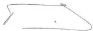
Philippe Vankerkhove
PerynaOnHHn Bbnpocn-MeHnJXkpno CbOTBeTCTBnraTa
28/06/2022, Lier - Belgium
POWERPLUS POWEG2010 LV
1 PAREDZETAIS LIETOJUMS. 3
2 APRAKSTS (A ATTELS) 3
3 IEPAKOJUMA SATURA SARAKSTS. 4
4 APZIMEJUMI 4
5 DROsIBA 4
6 DROsIBAS PASAKUMI SAISTIBARATSITIENU 5
7 MONTAZA 6
7.1 Montazas instrumenti 6
7.2 Montazas nosacijumi.. 7
7.3 Vadsliedes /zaga kedes/sajuga parsega uzstadiisana.. 7
7.3.1 Vadsliedes uzstadisana.. 7
7.3.2 Zaga kedes uzstadisana: 7
7.3.3 Zaga kedes spriegojuma regulesana 8
7.3.4 Zaga kedes reguleshana: 8
7.3.5 Kedes bremzes mehaniska pbaraude.. 8
7.3.6 Kedesbremzespärbaude: 9
8 DEGVIELA UN ELLOsANA 9
8.1 Degviela. 9
8.2 Degvielas jauksana.. 9
8.2.1 Degvielas un elošanas symboli 9
8.2.2 Sajauksanas proportcija: 40 dalas benzina pret vienu dalu smervielas 10
8.2.3 leteicamas degvielas 10
8.2.4 Kedes un sleedes elošana 10
9 LIETOSANA 10
9.1 Pärbaudes pirms dzineja iedarbinăsanas (8. att.) 10
9.2 Auksta dzineja iedarbinasana 10
9.3 Silta dzineja iedarbinasana 10
9.4 Kad dzinejs parsatinats ar degvielu 10
9.5 Dzineja apturešana (9n. att.) 11
9.6 Kedes bremzes daribas paraude 11
9.7 Zaga kedes / sliedes elosana 11
POWERPLUS POWEG2010 LV
9.8 Automatiskais ellotajs 11
9.9 Visparigi zagesanas noradijumi.. 12
9.9.1 Kokugasana. 12
9.9.2 Atzarošana 13
9.9.3 Sagarumošana 13
9.9.4 Sagarumošana, izmantojot stakus 13
10 APKOPES NORADIJUMI 14
10.1 Preventiva apkope 14
10.2 Ziemasapkope 14
10.3 Gaisa filtrs 14
10.4 Degvielas filtrs (17. att.) 15
10.5 Aizdedzes svece 15
11 TIRISANA UN APKOPE 15
11.1 Zobrata zobu ellošana: 15
11.2 Vadsliedesapkope: 16
11.3 Kedes asinasa: 16
11.4 Vadsliede 17
11.5 Kedes apkope 17
12 TEHNISKIE DATI 18
13 TROKSNIS 18
14 MOTORZAGAUZGLABASANA 18
15 PROBLÉMU NOVERŠANA 19
16 GARANTIJA 20
17 VIDE 20
18 ATBILSTIBAS DEKLARACIJA 21
POWERPLUS POWEG2010 LV
BENZINA KÉDES MOTORZAGIS 37,2 CC 14" POWEG2010
1 PAREDZÉTAIS LIETOJUMS
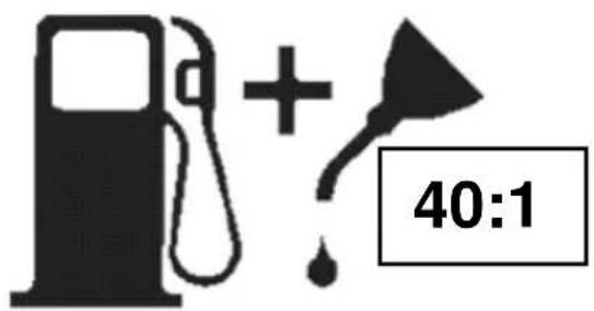
Oil only = Tikai e!!a

POWERPLUS POWEG2010 LV
8.2.2 Sajauksanas proporcija: 40 dalas benzina pret vienu dalu smervielas
| Litri benzīna | 1 | 2 | 3 | 4 | 5 |
| Divtaktu ellà, ml | 25 | 50 | 75 | 100 | 125 |
8.2.3 letecamas degvielas
Dazi standarta benzina veidi papildinati ar skabekli saturosam vielam, piemeram, spirtu vai eteri, lai atbilstu gaisa piesarnoesanas noteikumiem. Motors radits, lai labi darbotos ar jebkuru masinu benzinu, ieskaitot sos papildinatos benzina veidus, ja tiek ieverotas ieprieks minetas maisijuma proporcijas!
8.2.4 Kedes un sleedes ello'sana
Vienmér papildiniet kedes ellas tvertni ik reizi, kad tiek papildinata degvielas tvertne. lesakam izmantot musu mainas kedi un sliedi. Vienmér izmantojiet labas kvalitates kedes ellu, kas satur piejaukumus, kas mazina berzi un nodilumu un palidz noverst darvas veidosanos uz sliedes un kedes.
9 LIETOSANA
9.1 Pärbaudes pirms dzineja iedarbinăsanas (8. att.)

BRIDINAJUMS: nekad neiedarbiniet un nelietojiet motorzagi, ja sliede un kede nav pareizi uzstadita.
Uzpildiet deqvielas tvertni (A) ar pareizu deqvielas maisijumu.
Uzpildiet ellas tvertni (B) ar pareizu kedes un sleedes ellu...
9.2 Auksta dzineja iedarbinasana
- Jedarbinjet kedes bremzi (pavirziet roku sarqu uz prieksu un jegarbinjet to) (9a, att.)
Lai jedarbinatu zagi, nospiediet sledzi (ON/OFF sledzi) ON (I) pozicijā (9b. att.).
Izvelciet varstu (A) lidz bridim, kad tasnofiksejas (9c. att.).
3 lidz 5 reizes nospiediet deqvielas sukni.
Novietojiet zagi uz cietas un lidzenas virmas. Ar kaju drosi nofikszejiet sviru, ka paradits attela. Vairakas reizes asi pavelciet starteri, lidz dzirdama aizdedzes skana (9d. att.).
Värsts automatiski izslegsies, kad pavilskiet droseli (9e. att.). - Stipri pavelciet starteri, lidz sak darboties motors (9f. att.).
Viegli jiespiediet droseli (9q. att.).
Pavelciet atpakal bremzes sviru, lai atlaistu kedes bredmi (9h. att.).
9.3 Silta dzineja jedarbinasana
- ledarbiniet kedes bremzi (9i. att.).
- lestatiet sledzi (on/off) ON(I) pozicijā (9i. att.).
Stipri pavelciet starteri, lidz motors sak darboties (9k, att.).
Viegli nospiediet droseli (91. att.). - Atlaidiet kedes bremzi (9m. att.).
9.4 Kad dzinejs parsatinats ar degvielu
Nonemiet gaisafiltru.
Nonemiet aizdedzes syeci.
Novietojiet 1erici 45^ lenki ar vadsliedi augsup.
- Paris reizes pavelciet startera auklu.
Notiriet un novietojiet atpakal aizdedzes sveci.
Novietojiet atpakal gaisa filtru un jegarbiniet bez yarsta.
POWERPLUS POWEG2010 LV
9.5 Dzineja apturešana (9n. att.)
15 PROBLEMU NOVER'SANA
28/06/2022, Lier - Belgium
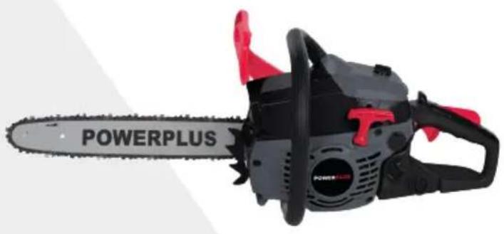
Vario
WWW.VARO.COM
DESIGNED AND MARKETED BY VARO
©copyright by varo
VARO - VIC. VAN ROMPUY nv
JOSEPH VAN INSTRAAT 9 - 2500 LIER - BELGIUM


- BESCHRIJVING (FIG A)
- PROBLEEMOPLOSSING
- POWERPLUS POWEG2010 FR
- DECLARATION OF CONFORMITY
- POWERPLUS POWEG2010 EN
- GASOLINE CHAINSAW 37.2CC 350MMPOWEG2010
- INTENDED USE
- DESCRIPTION (FIG A)
- PACKAGE CONTENT LIST
- SYMBOLS
- SAFETY
- KICKBACK SAFETY PRECAUTIONS
- ASSEMBLY
- Tools for assembly
- Assembly requirements
- Guide bar / saw chain / clutch cover installation
- To install the guide bar
- To install saw chain:
- Saw chain tension adjustment
- To adjust saw chain:
- Chain brake mechanical test
- To test chain brake:
- FUEL AND LUBRICATION
- Fuel
- Mixing fuel
- Fuel and lubrication symbols
- Recommended fuels
- Chain and bar lubrication
- OPERATION
- Engine pre start checks (Fig 8)
- Starting a cold engine
- Warm start
- When engine is saturated with fuel
- To stop engine (Fig 9n)
- Chain brake operational test
- Saw chain / bar lubrication
- Automatic oiler
- General cutting instructions
- Felling
- Felling cut:
- Limbing
- 9.9.3Bucking
- Bucking using a sawhorse
- MAINTENANCE INSTRUCTIONS
- Preventive maintenance
- Winter maintenance
- Air filter
- Caution: never operate saw without the air filter. Dust and dirt will be drawn into engine and damage it. Keep the air filter clean!
- Note: it is advisable to have a supply of spare filters.
- Warning: never perform maintenance when the engine is hot, to avoid any chance of burning hands or fingers.
- Fuel filter (Fig. 17)
- Note: do not pull hose completely out of tank.
- Spark plug
- CLEANING AND MAINTENANCE
- Sprocket tip lubrication:
- Guide bar maintenance:
- Chain sharpening:
- Guide bar
- Chain maintenance
- Chain lubrication:
- TECHNICAL DATA
- NOISE
- ATTENTION! Wear hearing protection when sound pressure is over 85 dB(A)
- STORING A CHAIN SAW
- TROUBLE SHOOTING
- WARRANTY
- ENVIRONMENT
- POWERPLUS POWEG2010 DE
- POWERPLUS POWEG2010 ES
- POWERPLUS POWEG2010 IT
- POWERPLUS POWEG2010 PT
- POWERPLUS POWEG2010 NO
- BENSINDREVET MOTORSAG 37.2CC 350MM POWEG2010
- TILTENKT BRUK
- Kontroll for start (Fig 8)
- POWERPLUS POWEG2010 DA
- Koldstart at motoren
- POWERPLUS POWEG2010 SV
- KONFORMITETSDEKLARATION
- POWERPLUS POWEG2010 FI
- POWERPLUS POWEG2010 EL
- BENZINOKINHTO AAYΣΟΠΡΙΟ N 37.2CC 14"POWEG2010
- PPOBAEIOMENH XP'H2H
- KATAANOFOE EAPTHMATON (XHMA A)
- SuvioTowevkaouia
- Aitavon aLuoiδac kalpaβδou
- AEITOYPTIA
- Ainavon aluoiδa κai paβδou
- O\$nyos paBos
- POWERPLUS POWEG2010 HR
- BENZINSKA MOTORNA PILA 37.2CC 14” POWEG2010
- NAMJENA
- OPIS (SL A)
- POWERPLUS POWEG2010 SR
- BENZINSKA LANČANA TESTERA 37.2CC 14” POWEG2010
- NAMENJENA UPOTREBA
- LISTASADRZAJAPAKETA
- SIMBOLI
- BEZBEDNOST
- MERE PREDOSTROZNOSTI ZA POVRATNI UDARAC
- MONTAZA
- Alati za montazu
- Uslovi za montazu
- Podesavanie zategnutosti lanca testere
- Zatezanje Ianca testere:
- Mehaničko ispitivanje kočnice lanca
- Kada je motor zasićen gorivom
- Zaustavljanje motora (SI. 9n)
- Operativna provera kočnice lanca
- Vazdušni filter
- Ostrenje Ianca:
- List testere
- Održavanje lanca
- TEHNIICKI PODACI
- BUKA
- SKLADIŠTENJE MOTORNE TESTERE
- MOGUĆI PROBLEMI IN NJIHOVO REŠAVANJE
- GARANCIJA
- ZIVOTNA OKOLINA
- IZJAVA O USKLADENOSTI
- POWERPLUS POWEG2010 CS
- BENZINOVA RETÉZOVÁ PILA 37.2CC 14" POWEG2010
- ZAMYŠLENÉ POUžITÍ
- POWERPLUS POWEG2010 SK
- BENZINOVA RETAZOVÁ PÍLA 37,2CC 14” POWEG2010
- ZAMYSL'ANE POUZITIE
- POWERPLUS POWEG2010 RO
- POWERPLUS POWEG2010 HU
- POWERPLUS POWEG2010 RU
- ZEHNHA BEH3OПЛА 37,2KyБ. CM - 14"POWEG2010
- NcNoJIb3OBAHHe NO HA3HAUeHnIO
- ONICAHNE (PNC.A)
- CODEPXMOE YNAKOBKN
- yCJIOBHBIE O6O3HAUeyHn
- INPABUNA TEXHNI B3ONACHOCTN
- PABUNA TEXHNI B3OINACHOCTN, CB3AHHBIE C OTDAUENIJIbI
- C6OPKA
- Hcmpymehmbi dna c6opku
- YcmaHOka nunbHou wuHbi / nunbHou cenu / KpbIwku cuenneHu
- YcTaHOBka NJIbHOH WnHbI
- YcTaHOBka NnIbHOu cenn:
- Perynupobka HataxeHna NnBHOIeenn
- PerynpoBka nIbHOn ueN:
- MexaHueckaj npOBepka cenHoro TopMo3a
- ПоберkaценHoroTopMo3a:
- TOPIIIBO N CMA3KA
- Tonnueo
- PpuzomoeHue monJueHoCmecu
- YcnoBhie 06o3HaueHn TaJIInBa n Cma3Kn
- IpeynycboI npoeepku deuzameJ (Puc. 8)
- 3anyck xonodhozo deueamej
- Fopauu nyck
- Kozda deusamelhacbiueH monluueom
- OcmahoeKa deusamei (Puc. 9n)
- Pnoeepka pa6ombl eHNO2 mOpMo3a
- Cma3b1aHue eenu / wuHbI
- Cucmema aemomamuueckozo cma3bieaHua
- Obuue uHcmpykuuu no nuneHuO
- Banka DepeBbeB
- O6pe3ka cybeB
- Bo3dyuHbI uJbmp
- HE INCIOJIb3yIte HNKAKNX DpynX IHCTPymeHTOB.
- XPAHEHNE UENHOI NJIbyI
- POWERPLUS POWEG2010 BG
- BEH3INHOB BEPUNKEH TPNOH 37.2CC 350MMPOWEG2010
- ПЕДHA3HAUECHNE HA YNOTPEБATA
- ONUCAHNE (FIG A)
- CnncbK HA CbIbPjXAHNETO HA IAKETA
- CMMBOJN
- MOHTAK
- Mohmaxhu uHcmpymemu
- N3uckeaHua 3a MOHmxa
- NocmaeHa Hanpaegnaa uHa / cepua Ha mpuHa / kanak Ha cbeuhumena
- 3a da noctabnte HanpaBnaBaata uHa
- 3a da MOHTnpaTe BepnxKnry TpnoH:
- 3a6eJekka: Bepurata Ha TpnoHa MoKe da npOBnche Jeko Bbpxy noHnckkata YacT Ha uHHata. TOBa e HopMaJIHo.
- 3a6eIeKka: KOHTparaiKITE Ha HAnpaBnBaUaTa 1HHa ca NoCTaBeHN B MOMeHTa CTeHato cAmo Ha pKa, 3aIoTO e Heo6xOIMo peryInpaHe Ha Bepurata Ha TpNoHa. CJeDbaiTe INcTpyKuInTe B pa3deJa PeryInpaHe Ha OINbHa Ha Bepurata Ha TpNoHa.
- PerynnpaHe Ha onbHa Ha BepuraTa Ha TpnoHa
- PpeynpeKdHHe: BnHaH NocTe 3aunTHn pBkaBn3a TeKKn ycNoBna Ha pa6Ota, Korato 6opabnte c Bepnrata Ha TpnoHa nIy KOpurpaTe.
- 3a da perynpuapeBepurataHa TpnoHa:
- MexaHnHNo n3nTahHe Ha BepnxHaTa cnnpaKa
- 3a da ce TecTbBepnXHaTa cnpaulyka:
- TOPINBO N CMA3BAHE
- Topueo
- CmecBaHe Ha zoPueo
- CnmboHn 3a ropuBO n cMa3BaHe
- Ta6nua 3a cMecBaHe Ha ropBO
- Cma3BaHe Ha Bepurata N uHnHaTa
- 9ФУHKLIOHNPAHE
- Ipecdmapmoeu npoeepku Ha deuzamena (Fua 8)
- Cmydeh cmapm
- Tonbl cmapm
- AemomamuHa MacJboHka
- 06u uHcmpkyu 3a p3aHe
- Поваяне
- Otcuzao p3aHe:
- KacTpeHe Ha KIOHn
- Pa3tpynBaHe
- Pa3tpynBaHe c n3non3BaHe Ha Marape
- INHCTPYKUN 3A NOIDPbXKA
- IpoqunakmuHa nooepbkk
- Nodopbxxka Ha Hanpaenreaaama wHa:
- Hamoyeane Ha cepueama:
- Hapnaeaea uHa
- NodobpkaHa Ha cepuzama
- CbXPAHRAHE HA BEPNJKEH TPOHO
- TAPAHÇΥ
- OKOJIHACPEDA
- DEKJIAPAUJ3A CbOTBETCTBNE
- POWERPLUS POWEG2010 LV
- BENZINA KÉDES MOTORZAGIS 37,2 CC 14" POWEG2010
- PAREDZÉTAIS LIETOJUMS
- letecamas degvielas
- Kedes un sleedes ello'sana
- LIETOSANA
- Pärbaudes pirms dzineja iedarbinăsanas (8. att.)
- Auksta dzineja iedarbinasana
- Silta dzineja jedarbinasana
- Kad dzinejs parsatinats ar degvielu
- Dzineja apturešana (9n. att.)
- PROBLEMU NOVER'SANA
- Vario
Brand : PowerPlus
Model : POWEG2010
Category : Saw