GRL 500 HV Professional - Laser level BOSCH - Free user manual and instructions
Find the device manual for free GRL 500 HV Professional BOSCH in PDF.
| Brand | Bosch |
| Model | GRL 500 HV Professional |
| Product type | Rotary laser level |
| Dimensions (L x W x H) | 234 x 217 x 194 mm |
| Weight | 2.3 kg (according to EPTA-Procedure 01:2014) |
| Power supply | Lithium-ion battery 7.4 V, 3 Ah |
| Battery life | Approx. 25 hours |
| Range (with receiver) | Up to 250 m (radius) |
| Leveling accuracy | ±0.1 mm/m (horizontal and vertical) |
| Self-leveling range | ±8.5 % (±5°) |
| Tilt mode on one axis | ±8.5 %, adjustable via keypad |
| Laser class | 2 (635 nm, <1 mW) |
| Main functions | Self-leveling, centerline mode, anti-drift system (ADS), anti-theft alarm, standby mode, calibration check |
| Receiver/remote control | LR 50, remote range up to 150 m |
| Maintenance and cleaning | Clean with a soft, damp cloth; do not use detergents or solvents |
| Safety | Class 2 laser; do not direct beam at people or animals; Strobe Shield™ protection against light interference |
| Spare parts and repairability | Bosch after-sales service; repairs only by qualified personnel with original parts |
| Operating temperature | -10°C to +50°C |
| Protection rating | IP 56 (dust-tight and protected against water jets) |
| Included accessories | Charger, LR 50 receiver, target holder, case (depending on version) |
Frequently Asked Questions - GRL 500 HV Professional BOSCH
User questions about GRL 500 HV Professional BOSCH
0 question about this device. Answer the ones you know or ask your own.
Ask a new question about this device
Download the instructions for your Laser level in PDF format for free! Find your manual GRL 500 HV Professional - BOSCH and take your electronic device back in hand. On this page are published all the documents necessary for the use of your device. GRL 500 HV Professional by BOSCH.
USER MANUAL GRL 500 HV Professional BOSCH
OB_HUC1960-005.book Page 1 Tuesday, March 27, 2018 12:07 PM
Robert Bosch Power Tools GmbH
70538 Stuttgart
SEHANY
www.bosch-pt.com
1609924DX[2018.03T/623

160992A4DX
GRL Professional
500H|500HV
LR 50 Professional
enOriginal instructions
nive of grade
es
pki kngn ngi it stang ngne
nCorsaonkeike gebuiasaariline
da Originalbragsanvising
SV Bruksarvnsing /artin
no Original driftsinstrute
fikuperaiet ojeet
eigntiinrnnnrrn rnrnnn nnnnne
pl instrukja orygrinalna
Pawodni Awad (pouyavani)
sk Povodny naod na potzite
Hueererererererererererererer
Purpanmukh 1968 pynoic 100
1
K
2017年4月1日
ro insturtctrnc prinpale
BcCnHnHaAeCTaH
mKCHHANHOYXETTOA

BOSCH
sr Originalno uputstvo zara
sIyima nayocia
hr Original uprite 24 rad
et ngipane kssitjurero
Wnss
1
1
10


Deutsch. 11
English 31
Francais . 50
Espanol. 70
Portugues. 90
Italiano 110
Nederlands.. 130
Dansk .Side 149
Svenska Sida 167
Norsk. Side 185
Suomi . Sivu 203
EAAyuká 222
Türkce Sayfa 242
Polski Strona 261
Cesky Strana 282
Slovensky Strana 301
Magyar Oldal 320
Pycckn CtpaHua 339
YkpaHcbKa. CtopiHa 361
Kaazakwa 382
Romana. 402
Блгарск.. .. 421
MaKeIOHcN CtpaHa 442
Srpski Strana 462
Slovensko. 481
Laser Radiation Class 2 do not stare into beam IEC 60825-1:2014 <1mW,635 nm
Laser Receiver/Remote Control 33
Product Description and Specifications 33
Intended Use 33
Rotational Laser Level GRL 500 H 33
Rotational Laser Level GRL 500 HV 33
Laser Receiver LR 50. 34
Product Features 34
Technical Data 35
Assembly 36
Charging the Batteries of the Measuring Tool and
Laser Receiver (see figures A-B) 36
Charge-control Indicator 36
Battery Charging 37
Recommendations for Optimal Handling of the Battery 37
Operation 37
Initial Operation 37
Setting Up the Measuring Tool 37
Operating the Measuring Tool (see figure C) 37
Operating States 37
Switching On and Off 37
Initial Operation 38
Switching On 38
Switching Off 38
Sleep Mode 38
Automatic Shutdown 38
RTC (Real Time Clock) Battery 39
Theft Alarm System 39
Activating the Theft Alarm System 39
Applications of the Theft Alarm System 39
Indicators for Checking Calibration (Calibration Warning) 39
Switching Off the Calibration Warning Indicators 39
Recommended procedure after an indication to check calibration 40
Operating Modes 40
Orientation of X- and Y-Axis 40
Rotational Operation 40
Operating Modes Overview 40
Automatic Levelling 40
Automatic Levelling after Switching On 40
Automatic Levelling during Operation 40
Single-axis Slope Operation 40
Slope Setting 40
Centre Line Mode (see figure D) 40
Speeding Up Finding the Centre Line of the
Laser Receiver 41
Anti-Drift System (ADS) 41
Deactivating the Anti-Drift System 41
Line Control in Vertical Mode (GRL 500 HV) 41
Centre Line Mode in Line Control (see figure E) 41
Speeding Up Finding the Centre Line of the
Laser Receiver 42
Relative Height Display (see figure F) 42
Working with the Laser Receiver 42
RF Communication between Measuring Tool and Remote Control/Laser Receivers 42
Setting the Audio Signal/Volume 42
Selecting the Setting of the Centre Line Indicator 43
Direction Indicators 43
Strobe shieldTM Protection 43
Marking 43
Display Illumination 43
Attaching with the Measuring Rod Clamp (see figure G) 43
Accuracy Check of the Measuring Tool 43
Influences on Accuracy 43
Checking the Levelling Accuracy in the Horizontal Position 44
Checking the Levelling Accuracy in the Vertical Position (GRL 500 HV) 44
Calibrating the Measuring Tool 44
X-Axis Calibration 44
Y-Axis Calibration 45
Z-Axis Calibration (GRL 500 HV) 45
Working Advice 46
Setting the Display of the Units 46
Laser Viewing Glasses (Accessory) 46
Working with the Tripod (Accessory) 46

32 | English
Working with Wall Mount/Alignment Unit (Accessory) 46
Working with the Measuring Rod (Accessory)
(see figure H) 46
Work Examples 46
Checking the Depth of Building Pits (see figure I) 46
Correction of Malfunctions 47
Malfunctions with Error Codes 47
Malfunctions without Error Codes 48
Maintenance and Service 48
Maintenance and Cleaning 48
After-sales Service and Application Service 48
Great Britain 48
Ireland 48
Australia, New Zealand and Pacific Islands 49
Republic of South Africa 49
Transport 49
Disposal 49
Great Britain 49
Safety Notes
Rotational Laser Level

All instructions must be read and observed in order to work safely with the measuring tool. The integrated protections in the measuring tool may be compromised if the measuring tool is not used in accordance
with the instructions provided. Never make warning signs on the measuring tool unrecognisable. STORE THESE INSTRUCTIONS IN A SAFE PLACE AND INCLUDE THEM WITH THE MEASURING TOOL WHEN GIVING IT TO A THIRD PARTY.
- Caution - The use of other operating or adjusting equipment or the application of other processing methods than those mentioned here can lead to dangerous radiation exposure.
The measuring tool is provided with a warning label (marked with number 8 in the representation of the measuring tool on the graphics page).
Laser Radiation Class 2 do not stare into beam IEC 60825-1:2014 <1mW,635 nm
If the text of the warning label is not in your national language, stick the provided warning label in your national language over it before operating for the first time.

Do not direct the laser beam at persons or animals and do not stare into the direct or reflected laser beam yourself, not even from a distance. You could blind somebody, cause accidents or damage your eyes.
If laser radiation strikes your eye, you must deliberately close your eyes and immediately turn your head away from the beam.
Do not make any modifications to the laser equipment.
Do not use the laser viewing glasses as safety goggles. The laser viewing glasses are used for improved visualisation of the laser beam, but they do not protect against laser radiation.
Do not use the laser viewing glasses as sun glasses or in traffic. The laser viewing glasses do not afford complete UV protection and reduce colour perception.
Have the measuring tool repaired only through qualified specialists using original spare parts. This ensures that the safety of the measuring tool is maintained.
Do not allow children to use the laser measuring tool without supervision. They could unintentionally blind other persons or themselves.
Do not operate the measuring tool in explosive environments, such as in the presence of flammable liquids, gases or dusts. Sparks can be created in the measuring tool which may ignite the dust or fumes.

Protect the measuring tool against heat, e.g., against continuous intense sunlight, fire, water, and moisture. Danger of explosion.
Under abusive conditions, liquid may be ejected from the battery; avoid contact. If contact accidentally occurs, flush with water. If liquid contacts eyes, additionally seek medical help. Liquid ejected from the battery may cause irritations or burns.
In case of damage and improper use of the battery, vapours may be emitted. Ventilate the area and seek medical help in case of complaints. The vapours can irritate the respiratory system.
Charge the battery pack only with the battery charger provided. A charger that is suitable for one type of battery pack may create a risk of fire when used with another battery pack.

Keep the measuring tool and the laser target plate away from cardiac pacemakers. The magnets of the measuring tool and laser target plate generate a field that can impair the function of cardiac pacemakers.
- Keep the measuring tool and the laser target plate away from magnetic data medium and magnetically-sensitive equipment. The effect of the magnets of the measuring tool and laser target plate can lead to irreversible data loss.

Battery Charger

Read all safety warnings and all instructions. Failure to follow the warnings and instructions may result in electric shock, fire and/or serious injury.
This charger is not intended for use by children and persons with physical, sensory or mental limitations or a lack of experience or knowledge. This charger can be used by children aged 8 and above and by persons who have physical, sensory or mental limitations or a lack of experience or knowledge if a person responsible for their safety supervises them or has instructed them in the safe operation of the charger and they understand the associated dangers. Otherwise, there is a danger of operating errors and injuries.
Supervise children during use, cleaning and maintenance. This will ensure that children do not play with the charger.

Keep the battery charger away from rain or moisture. Penetration of water in the battery charger increases the risk of an electric shock.
Charge the measuring tool only with the supplied charger.
- Keep the battery charger clean. Contamination can lead to danger of an electric shock.
Before each use, check the battery charger, cable and plug. If damage is detected, do not use the battery charger. Never open the battery charger yourself. Have repairs performed only by a qualified technician and only using original spare parts. Damaged battery chargers, cables and plugs increase the risk of an electric shock.
Do not operate the battery charger on easily inflammatble surfaces (e.g., paper, textiles, etc.) or surroundings. The heating of the battery charger during the charging process can pose a fire hazard.
In case of damage and improper use of the battery pack, vapours may be emitted. Provide for fresh air and seek medical help in case of complaints. The vapours can irritate the respiratory system.
- Products sold in GB only: Your product is fitted with a BS 1363/A approved electric plug with internal fuse (ASTA approved to BS 1362). If the plug is not suitable for your socket outlets, it should be cut off and an appropriate plug fitted in its place by an authorised customer service agent. The replacement plug should have the same fuse rating as the original plug. The severed plug must be disposed of to avoid a possible shock hazard and should never be inserted into a mains socket elsewhere.
Laser Receiver/Remote Control

Read and observe all instructions. SAVE THESE INSTRUCTIONS FOR FUTURE REFERENCE.
Have the measuring tool repaired only through qualified specialists using original spare parts. This ensures that the safety of the measuring tool is maintained.
Do not operate the measuring tool in explosive environments, such as in the presence of flammable liquids, gases or dusts. Sparks can be created in the measuring tool which may ignite the dust or fumes.

Protect the measuring tool against heat, e.g., against continuous intense sunlight, fire, water, and moisture. Danger of explosion.
Under abusive conditions, liquid may be ejected from the battery; avoid contact. If contact accidentally occurs, flush with water. If liquid contacts eyes, additionally seek medical help. Liquid ejected from the battery may cause irritations or burns.
In case of damage and improper use of the battery, vapours may be emitted. Ventilate the area and seek medical help in case of complaints. The vapours can irritate the respiratory system.
Charge the battery pack only with the battery charger provided. A charger that is suitable for one type of battery pack may create a risk of fire when used with another battery pack.
Product Description and Specifications
Intended Use
Rotational Laser Level GRL 500 H
The measuring tool is intended for determining and checking precise horizontal partitions.
The measuring tool is intended for outdoor use, but can also be used indoors.
Rotational Laser Level GRL 500 HV
The measuring tool is intended for determining and checking precise horizontal partitions, vertical lines, building lines and plumb points.
The measuring tool is intended for outdoor use, but can also be used indoors.


34 | English
Laser Receiver LR 50
The laser receiver is designed to quickly locate rotating laser beams and to remote-control the rotational laser level.
The laser receiver is suitable for indoor and outdoor use.
Note: The LR 50 functions both as a laser receiver and as a remote control. To make descriptions and instructions easier to read, the LR 50 is referred to only as a "laser receiver" in the following text.
Product Features
The numbering of the product features refers to the illustration of the rotational laser level, battery charger and laser receiver on the graphics page.
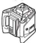
Rotational Laser Level
1 Plumb beam (GRL 500 HV)
2 Laser beam outlet
3 Prism cover (aluminium, glass)
4 Theft alarm LED
5 Charge contacts for laser receiver
6 Charging/storage station for laser receiver
7 Laser beam
8 Laser warning label
9 Serial number of the rotational laser level
10 Tripod mount 5 / 8'' (vertical) (GRL 500 HV)
11 Charge socket cover
12 Tripod mount 5 / 8^n (horizontal)
13 Reset button
14 Socket for charge connector
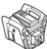
Laser Receiver
15 Display
16 Centre mark
17 On/Off button
18 Slope button, up
19 Centre line mode button
20 Slope button, down
21 Sleep mode button
22 Theft alarm button
23 Button for selecting the measuring accuracy
24 Audio signal/volume button
25 Calibration button
26 Reception area for the laser beam
27 Serial number of laser receiver
28 Charge contacts
Indicator elements of laser receiver
29 Battery charge-control indicator for rotational laser level
30 Battery charge-control indicator for laser receiver
31 Text display for slope/error
32 Text display for relative height/calibration interval
33 RF communication indicator
34 Out-of-temperature-range indicator
35 Calibration interval indicator
36 Theft alarm indicator
37 Out-of-level indicator
38 Shock-warning indicator
39 Direction indicator "move upward"
40 Direction indicator "move downward"
41 Slope mode indicator
42 Centre line mode indicator
43 Centre line indicator
44 Sleep mode indicator
45 Indicator for audio signal/volume
46 Indicator for measuring accuracy "Fine"
47 Indicator for measuring accuracy "Medium"
48 Indicator for measuring accuracy "Coarse"
Charger
49 Battery charger
50 Charge connector
51 Connector plug
52 Power plug
Accessories/Spare parts
53 Measuring rod clamp
54 Locking screw for measuring rod clamp
55 Construction laser measuring rod
56 Fastening screw for measuring rod clamp
57 Spirit level of measuring rod clamp
58 Slot for laser receiver
59 Wall mount/alignment unit
60 Fastening screw of the wall mount
61 Screw of the alignment unit
62 5/8" screw on wall mount
63 Tripod
64 Laser viewing glasses
65 Case
*Accessories shown or described are not part of the standard delivery scope of the product. A complete overview of accessories can be found in our accessories program.

English | 35
Technical Data
| Rotational Laser Level | GRL 500 H | GRL 500 HV |
| Article number | 3601 K61 A.. 3601 K61 B.. | |
| Working range (radius) | ||
| - without laser receiver, approx. 1) | 10 m | 10 m |
| - with laser receiver, approx. | 250 m | 250 m |
| Levelling Accuracy 2)3) | ||
| - Horizontal | ±0.1 mm/m | ±0.1 mm/m |
| - Vertical | - | ±0.1 mm/m |
| Self-levelling range, typically | ±8.5% (±5°) ±8.5% (±5°) | |
| Levelling duration, typically | 15 s 15 s | |
| Rotational speed | 600 min-1 | 600 min-1 |
| Single-axis slope operation (adjustable via keypad and display) | ±8.5% | ±8.5% |
| Accuracy2) | ±0.1% | ±0.1% |
| Theft alarm system | ● | ● |
| Calibration interval indicator | ● | ● |
| Operating temperature | -10...+50°C -10...+50°C | |
| Storage temperature | -20...+70°C -20...+70°C | |
| Relative air humidity, max. | 90% 90% | |
| Max. altitude | 2000 m 2000 m | |
| Laser class | 2 | 2 |
| Laser type | 635 nm, <1 mW | 635 nm, <1 mW |
| Divergence of laser line | 0.4 mrad (full angle) | 0.4 mrad (full angle) |
| Laser beam Ø at the exit opening, approx. 2) | 4 mm | 4 mm |
| Operating frequency range | 863-870 MHz | 863-870 MHz |
| Max. transmit power | 20 mW | 20 mW |
| Tripod mount | ||
| - Vertical | 5/8" | 5/8" |
| - Horizontal | - | 5/8" |
| Weight according to EPTA-Procedure 01:2014 | 2.3 kg | 2.3 kg |
| Dimensions (length x width x height) | 234 x 217 x 194 mm | 234 x 217 x 194 mm |
| Degree of protection | IP 56 (protected against dust and powerful water jets) | IP 56 (protected against dust and powerful water jets) |
| Battery | Li-Ion | Li-Ion |
| Rated voltage | 7.4 V | 7.4 V |
| Capacity | 3 Ah | 3 Ah |
| Number of battery cells | 4 | 4 |
| Operating time, approx. | 25 h | 25 h |
| 1) The working range (radius) can be reduced due to unfavourable ambient conditions (e.g. direct sunlight). | ||
| 2) at 20 °C | ||
| 3) alongside the axes | ||
| For clear identification of your rotational laser level, see the serial number 9 on the type plate. | ||


36 | English
| Laser Receiver/Remote Control LR 50 | |
| Article number | 3601 K69 A.. |
| Receivable wavelength | 625-645 nm |
| Working range (radius)1)2) | |
| -Laser Receiver with Rotational Laser Level | 250 m |
| -Remote Control | 150 m |
| Receiving angle | 70° (±35°) |
| Measuring accuracy3) | |
| -Setting "fine" | ±1 mm ±2 mm |
| -Setting "medium" | ±3 mm ±5 mm |
| -Setting "coarse" | ±7 mm ±10 mm |
| Display size | 62 x 31 mm |
| Reception area | 100 x 18 mm |
| Operating temperature | -10°C ... +50°C |
| Storage temperature | -20°C ... +70°C |
| Relative air humidity, max. | 90 % |
| Max. altitude | 2000 m |
| Operating frequency range | 863-870 MHz |
| Max. transmit power | 20 mW |
| Activation setting for sleep mode | |
| -After 30 mins without button press | ● |
| -After 30 mins without any laser detection | ● |
| Theft alarm system | 0-150 m |
| Calibration interval indicator | ● |
| Weight according to EPTA-Procedure 01:2014 | 0.3 kg |
| Dimensions (length x width x height) | 152 x 77 x 32 mm |
| Degree of protection | IP 56 (protected against dust and powerful water jets) |
| Battery | Li-Ion |
| Rated voltage | 7.4 V |
| Capacity | 1 Ah |
| Number of battery cells | 2 |
| Operating time, approx. | 25 h4) |
| 1) The working range (radius) can be reduced due to unfavourable ambient conditions (e.g. direct sunlight). | |
| 2) depends on clearance between laser receiver and rotational laser level | |
| 3) at a distance of 30 m | |
| 4) with display illumination deactivated | |
| The serial number 27 on the type plate is used to clearly identify your laser receiver/remote control. | |
| Battery Charger | |
| Article number 2 610 A16 4.. | |
| Charging time | approx. 3 h |
| Output voltage | 12 V= |
| Charging current | 5 A |
| Protection class | ☐/II |
Assembly
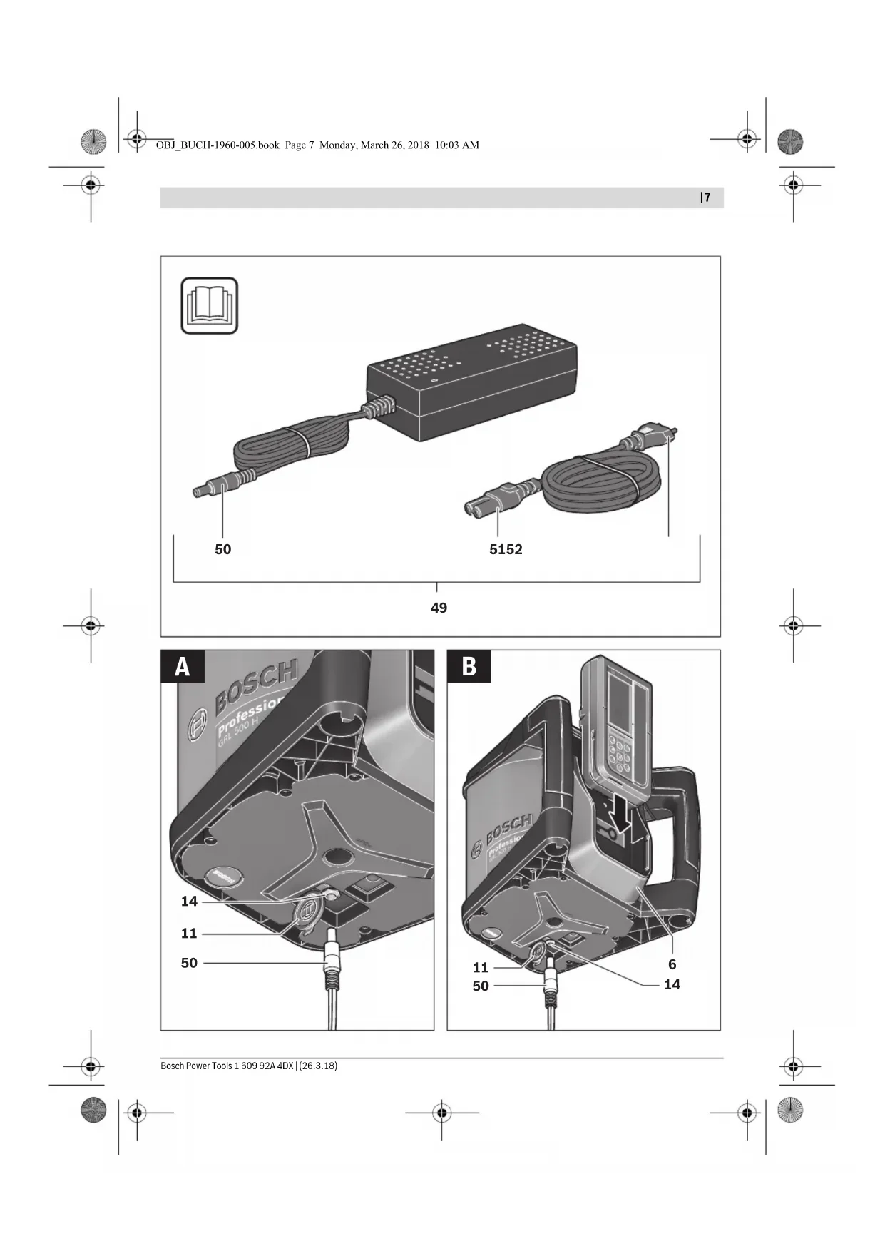
Charging the Batteries of the Measuring Tool and Laser Receiver (see figures A-B)
Do not use a different battery charger. The battery charger provided is matched to the lithium-ion battery installed in your measuring tool.
Observe the mains voltage! The voltage of the power source must correspond with the data on the type plate of the battery charger.

IMPORTANT The measuring tool and laser receiv- er must be charged only in dry in
door areas. The charging cable is not permitted for charging outdoors or in moist environments.
Note: The batteries of the measuring tool and laser receiver are supplied partially charged. To ensure full capacity of the batteries, completely charge the batteries before the first use.
The lithium-ion battery can be charged at any time without reducing its service life. Interrupting the charging procedure does not damage the battery.
Charge-control Indicator
The measuring tool must be switched on (see "Switching On", page 38) to display the battery charge status of the measuring tool and laser receiver.
| Display Indications | Meaning Capacity | Remaining measuring time, approx. | |
| 29 | Battery fully charged. | 60-100 % | 15-25 h |
| 30 | |||
| 29 | Battery partially charged. | 40-60 % | 10-15 h |
| 30 | |||
| 29 | Battery partially charged. | 20-40% | 5-10h |
| 30 | |||
| 29 | Battery partially charged. | 10-20% | 2.5-5 h |
| 30 | |||
| 29 | Battery should be recharged. | 0-10% | 0-2.5 h |
| 30 | |||
If the measuring tool is switched off and the laser receiver is in the charging/storage station 6, the battery charge status can be displayed as follows:

- Press the sleep mode button 21 until the audio signal sounds.
The battery charge-control indicators 29 and 30 are displayed.
The display illumination switches off again after 5 s.
1609 92A4DX|(28.3.18)BoschPowerTools


Battery Charging
-
Clean soiled charger contacts using a dry cloth.
-
Plug the charge connector 51 into the socket provided on the charger 49.
The measuring tool can be recharged independently of the laser receiver, however the laser receiver can only be recharged together with the measuring tool.
Measuring tool (see figure A):
- Open the cover 11 of the charge socket 14.
- Plug the power plug 52 of the power supply into the socket outlet and the charge connector 50 into the charge socket 14.
Laser Receiver (see figure B):
- Slide the laser receiver into the charging/storage station 6.
- Open the cover 11 of the charge socket 14.
- Plug the power plug 52 of the power supply into the socket outlet and the charge connector 50 into the charge socket 14.
Display Indicati
Meaning


Batteries charging.
The segments flash successively during charging.


The measuring tool and the laser receiver will switch off after charging.
Disconnect the battery charger from the mains supply when not using it for longer periods.
Protect the battery charger against moisture!
Recommendations for Optimal Handling of the Battery
Store the measuring tool and the laser receiver only within the permitted temperature range, see "Technical Data". As an example, do not leave them in the car in summer.
A significantly reduced working period after charging indicates that the battery is used and must be replaced.
Observe the notes for disposal.
Operation
Initial Operation
- Keep the measuring tool and the laser receiver dry and protect them from direct sunlight.
Do not expose the measuring tool and the laser receiver to extreme temperatures or variations in temperature. For example, do not leave them in a car for extended periods of time. In case of large variations in temperature, allow the measuring tool and the laser receiver to adjust to the ambient temperature before putting them into operation. The precision of the measuring tool and the laser receiver may be compromised if exposed to extreme temperatures or variations in temperature. - Avoid heavy impact to or falling down of the measuring tool. After severe exterior effects to the measuring tool, it is recommended to carry out an accuracy check (see "Accuracy Check of the Measuring Tool", page 43) each time before continuing to work.
Setting Up the Measuring Tool
Horizontal mode (GRL 500 H/ GRL 500 HV)
Vertical mode (GRL 500 HV)
- Position the measuring tool on a stable surface in the horizontal or vertical position, mount it to a tripod or to the wall mount 59 with alignment unit.
Due to the high levelling accuracy, the measuring tool reacts sensitively to ground vibrations and position changes. Therefore, pay attention that the position of the measuring tool is stable in order to avoid operational interruptions due to levelling.
Operating the Measuring Tool (see figure C)
The measuring tool is operated using the buttons on the laser receiver. Operation can be carried out either directly at the measuring tool (laser receiver docked in charging/storage station 6) or via RF communication (laser receiver acts as a remote control).
Operating States
The system consisting of measuring tool and laser receiver knows 3 operating states:
-Operating
All functions of the measuring tool and laser receiver are activated. See "Switching On", page 38.
- Sleep mode
To save energy, most of the functions of the measuring tool are deactivated for 2 h maximum.
The theft alarm system and the anti-drift system are still activated.
All settings (audio signal/volume, measuring accuracy, slope, etc.) are saved.
See "Sleep Mode", page 38.
- Switched off
All functions of the measuring tool and laser receiver are deactivated.
See "Switching Off", page 38, and "Automatic Shutdown", page 38.
Switching On and Off
Do not point the laser beam at persons or animals and do not look into the laser beam yourself, not even from a large distance.
Do not leave the switched-on measuring tool unattended and switch the measuring tool off after use. Other persons could be blinded by the laser beam.
Note: Before using the measuring tool, you should always perform an accuracy check (see "Accuracy Check of the Measuring Tool", page 43).
38|English
Initial Operation
Note: In their delivery condition, the measuring tool and laser receiver are paired (= laser receiver can perform the remote control functions).
To save energy, only switch the measuring tool and the laser receiver on when you are using them.
Switching On

- To switch on the measuring tool, slide the laser receiver into the charging/storage station 6 and then press the On/Off button 17.
or
- Slide the laser receiver into the charging/storage station 6 and remove it from the charging/storage station again. To switch on the measuring tool, you then have to press the On/Off button 17 within 30 minutes.
Outcome
- All display indicators light up briefly.
Automatic levelling starts (see "Automatic Levelling", page 40).
The anti-drift system is activated 30 s after automatic levelling (see "Anti-Drift System (ADS)", page 40).
The measuring tool then emits the laser beam 7 (GRL 500 H) or the laser beam 7 and the plumb beam 1 (GRL 500 HV).
Switching Off

- Press the On/Off button 17 for approx. 2 s.
Outcome
- The rotation stops and the laser beam is switched off.
- All display indicators and the display illumination are switched off.
Note: If the laser receiver and the rotational laser level are switched off, the laser receiver first has to be docked back in the charging/storage station 6 to switch the tool on.
Sleep Mode
The laser receiver can be used to put the measuring tool into sleep mode for maximum 2 hours.

-To switch on sleep mode, press the sleep mode button 21.

In sleep mode, the sleep mode indicator 44 on the laser receiver lights up and the theft alarm indicator 36 also lights up if the theft alarm system is activated.

The theft alarm LED 4 on the measuring tool flashes if the theft alarm system is activated.
All other indicators and the laser beam are switched off. The anti-drift system remains activat ed.

-To end sleep mode, press the sleep mode button 21 again.
Sleep mode is automatically switched on if the laser beam does not run through the reception area 26 for more than 30 minutes or the buttons on the laser receiver are not pressed for more than 30 minutes.
Note: If the laser receiver and the rotational laser level are in sleep mode for more than 2h both are automatically switched off. The laser receiver first has to be docked back in the charging/storage station 6 to switch the tool on.
The standard setting on delivery is [Sleep mode function deactivated]


To activate the sleep mode function, simultaneously press the On/Off button 17 and the sleep mode button 21 for approx. 2 s while the measuring tool is switched on.
The new state [Sleep mode function activated = SLP On] and the sleep mode indicator 44 will be shown on the display for approx.3s.
This setting is not saved when the tool is switched off. The measuring tool always starts up with the sleep mode function deactivated.
- To deactivate the sleep mode function, simultaneously press the On/Off button 17 and the sleep mode button 21 for approx. 2 s while the measuring tool is switched on.
The new state [Sleep mode function deactivated = SLP OFF] and the sleep mode indicator 44 will be shown on the display for approx.3s.
Automatic Shutdown
The measuring tool and the laser receiver switch off automatically under certain conditions (see "Switching Off", page 38 for outcome):
- The measuring tool is outside of the self-leveling range for more than 2.5 h and the error code resulting from this is not rectified (see "Correction of Malfunctions", page 47).
- The measuring tool is not switched on again within 2 h when sleep mode is activated.
- The anti-drift system is triggered for more than 2.5h
- The measuring tool is outside of the operating temperature range.

Before the measuring tool and laser receiver automatically switch off, an audio signal sounds and the out-of-temperature-range indicator 34 flashes for approx. 5 s.
English|39
After automatic shutdown:
- If applicable, wait until the measuring tool and the laser receiver are back in the operating temperature range.
- If required, reposition the measuring tool and switch it on again.
RTC (Real Time Clock) Battery

If the calibration interval indicator 35 flashes for approx. 10 s after the tool is switched on, the RTC battery and the integrated battery are weak. The calibration interval will no longer be monitored.
- Contact an authorised service agent for Bosch power tools.
Theft Alarm System
The system consisting of measuring tool and laser receiver has two security mechanisms to help prevent theft:
- The measuring tool can only be operated using the laser receiver; there is no control panel on the measuring tool.
- Both audible and visual indications are given on the measuring tool and on the laser receiver when the measuring tool is moved away from the reference point.
Activating the Theft Alarm System
The default setting in the delivery condition is [Theft alarm system deactivated].

- Press the theft alarm button 22 while the measuring tool is switched on.
The theft alarm system is activated.
The theft alarm indicator 36 and the theft alarm LED 4 light up.
The setting for the theft alarm system is saved when the tool is switched off.
To deactivate, press the theft alarm button 22 while the measuring tool is switched on.
Applications of the Theft Alarm System
| Application Security mechanism | |
| Measuring tool | Alarm system activated |
| switched on. | Theft alarm indicator 36 |
| or | lights up continuously |
| Measuring tool in sleep mode. | Theft alarm LED 4 flash- es slowly on the measur- ing tool |
| Measuring tool | Alarm system deactivated |
| switched off. | Theft alarm indicator 36 is not dis-played |
| Laser receiver | Theft alarm LED 4 does not light up on the measuring tool |
| switched off and not in the charging/storage station 6. |
If the theft alarm system is activated and the measuring tool moves away from the current location for more than 5 s, the alarm system will be triggered:
- An audio signal is emitted on the measuring tool and on the laser receiver.
The A-weighted sound pressure level of the audio signal is up to 110 dB(A) and cannot be adjusted using the volume setting of the normal audio signal.
Do not hold the laser receiver close to your ear! The loud audio signal can cause hearing defects.
- All operating functions are locked.

- The theft alarm LED 4 on the measuring tool flashes quickly.

- The theft alarm indicator 36 on the laser receiver flashes.

- To switch off the triggered alarm, press the theft alarm button 22.
The audio signal is switched off.
All operating functions are unlocked.
All settings are reset to the default settings when switching the tool on (see "Switching On", page 38).
The theft alarm system is activated again.
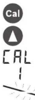
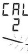
Indicators for Checking Calibration (Calibration Warning)
If the calibration of the measuring tool has to be checked, this is shown on the display of the laser receiver after switching on by means of various indicators in combination with the "CAL" indicator.
Note: The sensors for a calibration warning (calibration interval, storage temperature, shocks to the measuring tool) are active after the tool is started up for the first time.
Display Indications
Calibration warning

lights up
The calibration interval (every 12 months) has expired.
Calibration interval indicator 35 lights up

lights up
The measuring tool was stored outside of the storage temperature range.

Out-of-temperature-range indicator 34 lights up

lights up
The measuring tool suffered a severe shock (e.g. impact on the floor after a fall).

Shock warning indicator 38 lights up
The indicators for checking calibration are displayed for a short time, then go out and are not displayed again until the tool is switched on.
Switching Off the Calibration Warning Indicators
You can switch off the indicators until the cause of the calibration warning occurs again.

- Press the calibration button 25 for approx. 2 s while the calibration warning is being displayed. The indicators for checking calibration are not displayed again until the cause of the calibration warning occurs again.


40|English
Recommended procedure after an indication to check calibration
Step see
page
1 Check levelling accuracy 43
2a Deviation in 30 m is within the maximum permitted limits of ± 3.0mm
Switch off calibration warning indicators 39
2b Deviation in 30 m is outside of the maximum permitted limits of ± 3.0mm Calibrate measuring tool 44
3b Check levelling accuracy 43
4b Deviation in 30 m after calibration is within the maximum permitted limits of ± 3.0mm
Work can be performed without loss of accuracy.
Deviation in 30 m after calibration is still outside of the maximum permitted limits of ± 3.0mm
Have measuring tool checked by a Bosch customer service agent
Operating Modes
Orientation of X- and Y-Axis
The orientation of the X- and Y-axis is marked on the housing above the rotation head.
Rotational Operation
The measuring tool operates with a fixed rotational speed (600 rpm), which is suitable for use of a laser receiver.
Operating Modes Overview
- Automatic Leveling after switching on/during operation
- Single-axis Slope Operation
- Centre Line Mode
-Anti-Drift System(ADs) - Line Control in Vertical Mode (GRL 500 HV)
Automatic Levelling
Automatic Levelling after Switching On
After switching on, the measuring tool checks the horizontal position and automatically compensates for irregularities within the self-levelling range of approx. 8.5% (5^)
The out-of-level indicator 37 flashes during levelling.
GRL 500 HV: Once it has been switched on, the measuring tool automatically detects the horizontal or vertical position. To change between the horizontal and vertical position, you can reposition it without switching it off.
Automatic Levelling during Operation
If after a position change the measuring tool is outside of the self-leveling range of approx. 8.5% (5°), levelling is no longer possible and an error code is displayed (see "Correction of Malfunctions", page 47).
If the measuring tool is levelled, it constantly checks the level position. Re-levelling is automatically performed if there are any position changes. To prevent incorrect measurements, the rotation of the laser beam stops during the levelling process.
Single-axis Slope Operation
When the measuring tool is in the horizontal position, the X-axis is automatically levelled while in single-axis slope operation.
The rotational plane can be turned around the X-axis in a range of ± 8.5% .
Note: If you want to perform a slope setting immediately after switching on, you have to wait for the automatic levelling (see "Automatic Levelling after Switching On", page 40). This prevents incorrect measuring results.
Slope Setting
Slope setting is possible within a range of ± 8.5% .

- Press and hold the slope button 18 or 20 until the desired slope value is shown on the display.
- Let go of the slope button 18 or 20 again.
The out-of-level indicator 37 flashes during slope setting.

The slope mode indicator 41 lights up continuously.

- Simultaneously press the slope buttons 18 and 20.
Slope setting is deactivated.
Automatic levelling is activated (see "Automatic Levelling", page 40).


If the slope range of ± 8.5% is exceeded, the slope mode indicator 41 goes out and an error code is displayed (see "Correction of Malfunctions", page 47).
Centre Line Mode (see figure D)
In centre line mode, the measuring tool automatically tries to find the centre line of the laser receiver by moving the rotation head upward and downward.

- Press the centre line mode button 19 for approx. 2 s.
Automatic upward and downward movement of the rotation head starts.
Search Sequence:
- Rotation head pivots upwards to the stop.
- Laser beam is switched on.
- Rotation head pivots downwards.


English|41
4a. Laser beam hits the reception area 26 and finds the centre line.
or
4b. Laser beam reaches the end of the pivoting range without finding a reception area; an error code is displayed (see "Correction of Malfunctions", page 47).
The out-of-level indicator 37 flashes during the search for the centre line.
The indicators for centre line mode 42 light up continuously.
As soon as the laser beam hits the reception area 26, a beep sounds until the centre line is found.
The speed at which the rotation head moves will slow down as soon as the laser beam hits the reception area 26.
When the centre line has been found, the measuring tool automatically switches off the centre line mode. The set slope is saved and shown on the display.

-To cancel centre line mode during the search, press the centre line mode button 19. or

Simultaneously press the slope buttons 18 and 20 to activate automatic levelling.
Auto

Speeding Up Finding the Centre Line of the Laser Receiver
Searching for the centre line of the laser receiver always begins with an upward movement of the rotation head. The direction of the movement can be changed if the laser beam is below the centre line and not yet in the reception area of the laser receiver.

- Press the centre line mode button 19 for approx. 2 s.
Automatic upward and downward movement of the rotation head starts.
- Press the slope button 20. The rotation head is moved downwards.

Anti-Drift System (ADS)
The measuring tool has an anti-drift system; after position changes or shock to the measuring tool, or in case of ground vibrations, it keeps the measuring tool from levelling in at changed heights, and thus prevents vertical errors.

The anti-drift system is activated approx. 30 s after the measuring tool has been switched on.
During activation the shock-warning indicator 38 flashes slowly. The indicator lights up continuously after activation.
If the vertical position of the measuring tool is changed or a severe shock is registered, then the anti-drift system is triggered: the rotation of the laser is stopped and the shock warning indicator 38 flashes. In addition, a beep sounds for 5 s on the laser receiver.

- Press the On/Off button 17 briefly when the anti-drift system is triggered.
Automatic levelling starts (see "Automatic Leveling during Operation", page 40).
- Now check the height of the laser beam against a reference point and correct the height of the measuring tool if necessary.
Deactivating the Anti-Drift System
The anti-drift system can be deactivated during operation of the measuring tool.

- Press the On/Off button 17. The anti-drift system is deactivated. The shock warning indicator 38 is no longer displayed.
This setting is not saved when the tool is switched off. The measuring tool always starts with the anti-drift system activated.
Line Control in Vertical Mode (GRL 500 HV)
When the measuring tool is in the vertical mode, you can position the rotational plane along the X-axis for simple alignment or parallel alignment.

- To turn the rotational plane clockwise, press the slope button 18; to turn it counterclockwise, press the slope button 20.

Positioning is possible within a range of ± 8.5% .
The speed at which the rotation head moves begins slowly and continually increases.
Centre Line Mode in Line Control (see figure E)
In centre line mode, the measuring tool automatically tries to find the centre line of the laser receiver by moving the rotation head left and right.

-Press the centre line mode button 19 for approx. 2s
Automatic left/right movement of the rotation head starts.
Search Sequence:
- Rotation head pivots right to the stop.
- Laser beam is switched on.
- Rotation head pivots left.
4a. Laser beam hits the reception area 26 and finds the centre line.
or
4b. Laser beam reaches the end of the pivoting range without finding a reception area; an error code is displayed (see "Correction of Malfunctions", page 47).
42 | English
The out-of-level indicator 37 flashes during the search for the centre line.
The indicators for centre line mode 42 light up continuously.
As soon as the laser beam hits the reception area 26, a beep sounds until the centre line is found.
The speed at which the rotation head moves will slow down as soon as the laser beam hits the reception area 26. When the centre line has been found, the measuring tool automatically switches off the centre line mode.

- To cancel centre line mode during the search, press the centre line mode button 19.
or Simultaneously press the slope buttons 18 and 20 to activate automatic levelling.

Auto


Speeding Up Finding the Centre Line of the Laser Receiver
Searching for the centre line of the laser receiver always begins with a right-hand movement of the rotation head. The direction of the movement can be changed if the laser beam is to the left of the centre line and not yet in the reception area of the laser receiver.

-
Press the centre line mode button 19 for approx. 2s. The rotation head is automatically moved to the right.
-
Press the slope button 20. The rotation head is moved downwards.

Relative Height Display (see figure F)
The distance between the rotational plane and the centre line is shown on the display as an absolute value (in [mm] or [inch]). See also "Setting the Display of the Units", page 46.
Working with the Laser Receiver
For outdoor use or longer distances indoors, use the laser receiver to find the laser beam.
- Place the laser receiver so that the laser beam can reach the reception area 26.
RF Communication between Measuring Tool and Remote Control/Laser Receivers
In its delivery condition, the laser receiver provided LR 50 acts as a remote control for the measuring tool via a wireless connection.

- The RF communication indicator 33 is displayed to indicate the remote control function on the laser receiver.
Multiple laser receivers LR 50 can be assigned to the measuring tool.
-
Switch off the measuring tool and the laser receiver.
-
Dock the additional laser receiver in the charging/storage station 6.

- Press the On/Off button 17.

-
The RF communication indicator 33 is displayed to indicate the remote control function on the laser receiver.
-
Remove the laser receiver from the charging/storage station again. To switch on the measuring tool, you then have to press the On/Off button 17 within 30 minutes.
Note: If multiple laser receivers have been assigned to a measuring tool, then the last assigned laser receiver acts as the remote control. The other laser receivers are then purely laser receivers.
Settings such as measuring accuracy or audio signal can be set individually for each laser receiver.
If the remote control/laser receiver is switched off, the measuring tool switches off. All other laser receivers each have to switch off separately.

If the RF communication is lost, the RF communication indicator 33 flashes and an audio signal sounds.
This signals that warnings (e.g. theft, anti-drift, calibration) will not be shown and the measuring tool will no longer be remote-controlled.
Note: Sleep mode of the measuring tool can be switched on and off only by pressing the sleep mode button 21 on the remote control/laser receiver.
Setting the Audio Signal/Volume
The position of the laser beam on the reception area 26 can be indicated via an audio signal.
You can choose between two volumes or switch off the audio signal.
The default setting in the delivery condition is [Normal audio signal].
Press the audio signal/volume button 24 repeatedly until the desired setting is reached. No indicator: audio signal off

Normal audio signal

Loud audio signal
The setting for audio signal/volume is saved when the tool is switched off.


Selecting the Setting of the Centre Line Indicator
You can specify the accuracy with which the position of the laser beam is indicated as "centred" on the reception area.
The default setting in the delivery condition is [Measuring accuracy "medium/3 mm)].

- Press the measuring accuracy setting button 23 repeatedly until the desired setting is reached.
Example The measuring accuracy level "fine"/"me- dium"/coarse" and the exact value are shown on the display.
The setting for measuring accuracy is saved when the tool is switched off.
Direction Indicators
The position of the laser beam in the reception area 26 is indicated:
on the display 15 on the front and rear side of the laser receiver by the direction indicator "move upward" 39, the direction indicator "move downward" 40 or the centre line indicator 43.
- optionally by the audio signal.
Laser receiver too low: If the laser beam runs through the upper half of the reception area 26, then the direction indicator "move upward" 39 lights up and the plus value of the relative height display 32 shows how much the laser receiver has to be moved upwards. If the audio signal is switched on, a signal sounds in a slow rhythm.
- Move the laser receiver upwards in the arrow direction. When the centre mark 16 is approached, only the tip of the direction indicator 39 is shown.
Laser receiver too high: If the laser beam runs through the lower half of the reception area 26, then the direction indicator "move downward" 40 lights up and the minus value of the relative height display 32 shows how much the laser receiver has to be moved downwards.
If the audio signal is switched on, a signal sounds in a fast rhythm.
- Move the laser receiver downwards in the arrow direction. When the centre mark 16 is approached, only the tip of the direction indicator 40 is shown.
Laser receiver centred: If the laser beam runs through the reception area 26 at the height of the centre mark 16, then the centre line indicator 43 lights up. If the audio signal is switched on, a continuous tone sounds.
If the measuring tool is moved so that the laser beam leaves the reception area 26 again, the most recently displayed direction indicator 39 or 40 will flash for approx. 5 s.
Strobe shield™ Protection
The laser receiver has electronic filters for strobe light. The filters protect against, for example, interference from the warning lights of construction machinery.
Marking
When the laser beam runs through the centre of the reception area 26, its height can be marked at the centre mark 16 left and right of the laser receiver.
When marking, take care to align the measuring tool exactly vertical (for horizontal laser beam), or horizontal (for vertical laser beam), as otherwise the marks are offset with respect to the laser beam.
Display Illumination
The default setting in the delivery condition is [Display illumination activated].
If no button is pressed after approx. 30 seconds, the display illumination goes out.
When any button is pressed or when the laser beam hits the reception area, the display illumination is switched back on.

- To switch off the display illumination, simultaneously press the On/Off button 17 and the audio signal/volume button 24.

The setting for display illumination is saved when the tool is switched off.
Attaching with the Measuring Rod Clamp (see figure G)
With the measuring rod clamp 53, the laser receiver can be fastened to a construction laser measuring rod 55 (accessory) as well as to other auxiliary equipment with a width of up to 65mm .
- Fit the slot 58 to the measuring rod clamp 53 using the fastening screw 56.
- Loosen the locking screw 54, slide the measuring rod clamp onto the construction laser measuring rod 55, for example, and retighten the locking screw 54.
- The measuring rod clamp 53 can be horizontally aligned with help of the spirit level 57.
A measuring tool mounted out-of-level leads to faulty measurements.
- Slide the laser receiver into the slot 58.
Accuracy Check of the Measuring Tool
The following tasks should be performed only by well-trained and qualified persons. The legalities with regard to performing an accuracy check or calibration of a measuring tool must be known.
Influences on Accuracy
The ambient temperature has the greatest influence. Especially temperature differences occurring from the ground upward can divert the laser beam.
In addition to external influences, device-specific influences (e.g. falls or heavy impacts) can also lead to deviations. For this reason, check the calibration each time before beginning work.
The deviations play a role in excess of approx. 20m measuring distance and can easily reach two to four times the deviation at 100m .


44 | English
Because the largest difference in temperature layers is close to the ground, the measuring tool should always be mounted on a tripod when measuring distances exceeding 20m . If possible, also set up the measuring tool in the centre of the work area.
If the measuring tool exceeds the maximum deviation in one of the measuring procedures described below, perform a calibration (see "Calibrating the Measuring Tool", page 44) or have the measuring tool checked by a Bosch customer service agent.
Checking the Levelling Accuracy in the Horizontal Position
A free measuring distance of 30m on a firm surface in front of a wall is required for the check. A complete measuring procedure each must be carried out for the X- and Y-axis.
Mount the measuring tool in the horizontal position onto a tripod or place it on a firm and level surface at a distance of 30m to the wall. Switch the measuring tool on.
- After the levelling, mark the centre of the laser beam on the wall (point 1).
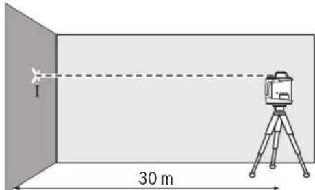
- Rotate the measuring tool by 180^ , allow it to level in and mark the centre point of the laser beam on the wall (point II). Take care that point II is as vertical as possible above or below point I.
- The difference d of both marked points 1 and 11 on the wall results in the actual height deviation of the measuring tool for the measured axis.
Repeat the measuring procedure for the other axis. For this, turn the measuring tool by 90^ before starting the measuring procedure.
The maximum permitted deviation on the 30m measuring distance is as follows:
30m× ± 0.1mm / m = ± 3.0mm.
The difference d between points I and II must therefore be maximum 6 mm in each of the two measuring procedures.
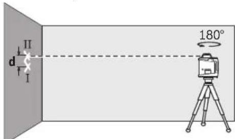
Checking the Levelling Accuracy in the Vertical Position (GRL 500 HV)
A free measuring distance of 10 m on a firm surface in front of a wall is required for the check. Fasten a plumb bob rope to the wall.
- Mount the measuring tool in the vertical position onto a tripod, or place it on a firm and level surface. Switch the measuring tool on and allow it to level.
Align the measuring tool such that the laser beam impinges centrally on the plumb bob rope at the upper end. The difference between laser beam and plumb bob rope at the bottom end of the rope results in the deviation of the measuring tool to the vertical line.
The maximum permitted deviation over a 10m high measuring distance is as follows:
10m× ± 0.1mm / m = ± 1mm
The difference d must therefore be maximum 1 mm.
Calibrating the Measuring Tool
The following tasks should be performed only by well-trained and qualified persons. The legalities with regard to performing an accuracy check or calibration of a measuring tool must be known.
Perform calibration of the measuring tool meticulously or have the measuring tool checked by a Bosch customer service agent. Inaccurate calibration leads to incorrect measuring results.
Start the calibration only if you have to perform a calibration of the measuring tool. As soon as the measuring tool is in calibration mode, you must perform the calibration meticulously to the end in order to ensure that no incorrect measuring results are produced afterwards.
Note: After calibration, the indicators for checking calibration are not displayed again until the cause of the calibration warning occurs again.
A free measuring distance of at least 30m on a firm surface in front of a straight wall is required for the calibration.
Always calibrate all axes (GRL 500 H: X-axis and Y-axis; GRL 500 HV: X-axis, Y-axis and Z-axis).
X-Axis Calibration
Mount the measuring tool in the horizontal position on a tripod 63 (accessory).
- Place the tripod 30m in front of the wall. The X-axis indicator imprinted on the measuring tool must be pointing perpendicular to the wall.
- Switch the measuring tool on.
English|45
- Simultaneously press the calibration button 25 and the slope button 18 for approx. 2 s.
The symbol for calibrating the X-axis is shown on the display.
The out-of-level indicator 37 flashes during automatic levelling.
- Wait until the measuring tool is levelled in.
- Use the laser receiver to find the centre line and transfer the height "X1" of the centre line onto the wall.
- Turn the measuring tool 180^ without adjusting the height of the tripod.
Wait until the out-of-level indicator 37 stops flashing and the measuring tool is levelled in. - Use the laser receiver to find the centre line and transfer the new height "X2" of the centre line onto the wall.
Determine the exact centre between the centre lines "X1" and "X2" and position the laser receiver on it using the centre mark 16.

Press the slope button 18 or 20 until the centre line indicator 43 lights up continuously. If the audio signal is switched on, a continuous tone sounds.
- Press the calibration button 25 to save the calibration.

The symbol for completing calibration is shown on the display.
In order to rule out faulty calibration after completion of the calibration, you must check the levelling accuracy (see "Checking the Levelling Accuracy in the Horizontal Position", page 44).
If the deviation is still outside of the maximum permitted limit of ± 3.0mm have the measuring tool checked by a Bosch customer service agent.
Y-Axis Calibration
- Mount the measuring tool in the horizontal position on a tripod 63 (accessory).
- Place the tripod 30m in front of the wall. The Y-axis indicator imprinted on the measuring tool must be pointing perpendicular to the wall.
- Switch the measuring tool on.

- Simultaneously press the calibration button 25 and the slope button 20 for approx. 2 s.
The symbol for calibrating the Y-axis is shown on the display.
The out-of-level indicator 37 flashes during automatic levelling.
- Wait until the measuring tool is levelled in.
- Use the laser receiver to find the centre line and transfer the height "Y1" of the centre line onto the wall.
Turn the measuring tool 180^ without adjusting the height of the tripod.
Wait until the out-of-level indicator 37 stops flashing and the measuring tool is levelled in. - Use the laser receiver to find the centre line and transfer the new height "Y2" of the centre line onto the wall.
Determine the exact centre between the centre lines "Y1" and "Y2" and position the laser receiver on it using the centre mark 16.

- Press the slope button 18 or 20 until the centre line indicator 43 lights up continuously. If the audio signal is switched on, a continuous tone sounds.
- Press the calibration button 25 to save the calibration.

The symbol for completing calibration is shown on the display.

In order to rule out faulty calibration after completion of the calibration, you must check the levelling accuracy (see "Checking the Levelling Accuracy in the Horizontal Position". page 44). If the deviation is still outside of the maximum permitted limit of ± 3.0mm have the measuring tool checked by a Bosch customer service agent.
Z-Axis Calibration (GRL 500 HV)
- Mark a vertical line on the wall using a plumb line.
- Mount the measuring tool in the vertical position on a tripod 63 (accessory).
- Place the tripod 5-10 m in front of the wall.
- Switch the measuring tool on.

- Simultaneously press the calibration button 25 and the slope button 18 for approx. 2 s.

The symbol for calibrating the Z-axis is shown on the display.
- Align the tripod so that the laser beam crosses the vertical line on the wall.
46|English
The out-of-level indicator 37 flashes during automatic levelling.
- Wait until the measuring tool is levelled in.

-
Press the slope button 18 or 20 until the laser beam is as parallel as possible to the vertical line on the wall.
-
If you do not achieve congruence, repeat the previous steps (align tripod, allow measuring tool to level in, align laser beam using slope buttons).

- Press the calibration button 25 to save the calibration.

The symbol for completing calibration is shown on the display.
In order to rule out faulty calibration after completion of the calibration, you must check the levelling accuracy (see "Checking the Levelling Accuracy in the Vertical Position". page 44).
If the deviation is still outside of the maximum permitted limit of ± 1mm have the measuring tool checked by a Bosch customer service agent.
Working Advice
The measuring tool is equipped with a radio interface. Local operating restrictions, e.g. in airplanes or hospitals, are to be observed.
Always use the centre of the laser line for marking. The width of the laser line changes with the distance.
Setting the Display of the Units
The distance between rotational plane and centre line is shown on the display in [mm] or [inch: decimals/fractions]. The default setting in the delivery condition is [mm].

- Simultaneously press the measuring accuracy setting button 23 and the slope button 20 repeatedly until the desired setting is reached.

The setting for the units is saved when the tool is switched off.
Laser Viewing Glasses (Accessory)
The laser viewing glasses filter out the ambient light. This makes the red light of the laser appear brighter for the eyes.
Do not use the laser viewing glasses as safety goggles. The laser viewing glasses are used for improved visualisation of the laser beam, but they do not protect against laser radiation.
- Do not use the laser viewing glasses as sun glasses or in traffic. The laser viewing glasses do not afford complete UV protection and reduce colour perception.
Working with the Tripod (Accessory)
The measuring tool is equipped with a 5/8 tripod mount for horizontal operation on a tripod. Place the measuring tool via the tripod mount onto the 5/8 male thread of the tripod and screw the locking screw of the tripod tight.
On a tripod 63 with a measuring scale on the elevator column, the height difference can be adjusted directly.
Working with Wall Mount/Alignment Unit (Accessory)
You can also mount the measuring tool to the wall mount with alignment unit 59. For this, screw the 5 / 8 screw 62 of the wall mount into the tripod mount of the measuring tool.
Mounting to a wall: Mounting to a wall is recommended, e.g., for work above the elevation height of tripods or for work on unstable surfaces and without tripod. For this, fasten the wall mount 59, with the measuring tool mounted, as vertical as possible to a wall.
For mounting to the wall, you can either fasten the wall mount 59 with fastening screw 60 to a lath (width maximal 8mm ) or hang it up with two hooks.
Mounting on a tripod: The wall mount 59 can also be screwed onto a tripod with the tripod mount on the back side. This method of fastening is especially recommended for work where the rotational plane is to be aligned with a reference line.
With the alignment unit, the mounted measuring tool can be moved vertically (when mounted to the wall) or horizontally (when mounted to a tripod) within a range of approx. 16 cm. For this, loosen screw 61 on the alignment unit, move the measuring tool to the desired position, and retighten screw 61 again.
Working with the Measuring Rod (Accessory) (see figure H)
For checking irregularities or projecting gradients, it is recommended to use the measuring rod 55 together with the laser receiver.
A relative millimetre scale (± 50~cm) is marked on the top of the measuring rod 55. Its zero height can be preset at the bottom of the elevator column. This allows for direct reading of deviations from the specified height.
Work Examples
Checking the Depth of Building Pits (see figure 1)
- Position the measuring tool on a firm surface or mount it to a tripod 63.
- Working with tripod: Align the laser beam to the requested height. Project or check the height at the target location. Working without tripod: Determine the height difference between the laser beam and the height at the reference point. Project or check the measured height difference at the target location.
When measuring over long distances, the measuring tool should always be set up in the centre of the work surface and on a tripod, in order to reduce interferences.
- When working on unstable ground, mount the measuring tool on the tripod 63. Ensure that the anti-drift system is activated in order to prevent incorrect measurements in the event of ground movements or shocks to the measuring tool.

Correction of Malfunctions
Malfunctions with Error Codes
The error code of a malfunction is shown on the display.
- Rectify the malfunction (see "Corrective Measure").

- Afterwards, simultaneously press the centre line mode button 19 and audio signal/volume button 24.
If the malfunction was successfully rectified, the error code indication goes out and automatic levelling will start (see "Automatic Levelling during Operation", page 40).
If the malfunction persists, have the measuring tool checked by a Bosch customer service agent.
| Error Code Indication | Problem Corrective Measure | |
| 001 The X-axis of the measuring tool is outside of the self-levelling range of approx. 8.5% (5°). | - Reposition the measuring tool along the X-axis. | |
| 002 The Y-axis of the measuring tool is outside of the self-levelling range of approx. 8.5% (5°). | - Reposition the measuring tool along the Y-axis. | |
| 003 (GRL 500 HV) | The Z-axis of the measuring tool in vertical mode is outside of the self-levelling range of approx. 8.5% (5°). | - Reposition the measuring tool in vertical mode along the Z-axis. |
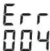
| 004 Measuring tool is at a slant of more than 8.5% after a position change. | - Reposition the measuring tool. | |
| The slope range of ±8.5% has been exceeded in single-axis slope operation. | - Press the slope button 18 or 20 until a slope value of less than 8.5% is shown on the display (see "Slope Setting", page 40). | |
| 005 Duration of automatic levelling has been exceeded. Measuring tool cannot be levelled in. | - Place the measuring tool on a stable surface or mount it in a stable manner on a tripod. The environment must be vibration-free. | |
| 006 The desired slope is not reached in single-axis slope operation. | - Place the measuring tool on a stable surface or mount it in a stable manner on a tripod. The environment must be vibration-free. | |
| 007 The rotation head of the laser is not rotating. | - Simultaneously press the centre line mode button 19 and audio signal/volume button 24. - Switch the measuring tool off (see "Switching Off", page 38). - Switch the measuring tool back on. | |
| 008 During the search in centre line mode, the laser beam reaches the end of the pivoting range without finding the reception area of the laser receiver. | - Check whether the visual contact between measuring tool and laser receiver has been interrupted and reposition the measuring tool if necessary. If the error continues to occur, reduce the distance between measuring tool and laser receiver. | |
| 009 External influences (e.g. falls or heavy impacts) are interfering with centre line mode. | - Reposition the measuring tool. - Place the measuring tool on a stable surface or mount it in a stable manner on a tripod. The environment must be vibration-free. - Restart the search to find the centre line (see "Centre Line Mode", page 40). Ensure that the pivoting range of the laser beam is not interrupted by persons or other visual obstacles during the search. If the error continues to occur, reduce the distance between measuring tool and laser receiver. | |
| 020 General error | - Simultaneously press the centre line mode button 19 and audio signal/volume button 24. - Switch the measuring tool off (see "Switching Off", page 38). - Switch the measuring tool back on. | |
| 033 Ambient light is too bright for the laser receiver. | - Shade the reception area. |
Bosch Power Tools 1609 92A 4DX(28.3.18)


48|English
Malfunctions without Error Codes
| Problem Corrective Measure | |
| Measuring tool or laser receiver cannot be switched on. | - Place the measuring tool on a stable surface or mount it in a stable manner on a tripod. The environment must be vibration-free. If the error persists, contact an authorised Bosch customer service agent. |
| - Charge the battery of the measuring tool (see "Charging the Batteries of the Measuring Tool and Laser Receiver", page 36). - Switch the measuring tool back on. If the error persists, contact an authorised Bosch customer service agent. | |
| Batteries of measuring tool and/or laser receiver are not being charged. | - Wait until the measuring tool and/or the laser receiver reach (return to) the optimum charging temperature range (0 °C ...+40 °C). |
| The battery of the laser receiver became empty while the measuring tool and laser receiver were switched on. | - Press the reset button 13. Measuring tool is switched off. |
| The laser receiver is defective, freezes or has been lost, and the theft alarm is triggered. | - Press the reset button 13. The audio signal and the measuring tool are switched off. |
| A temporary software malfunction is occurring on the laser receiver. | - To reset the laser receiver to the delivery condition, simultaneously press the On/Off button 17 and the measuring accuracy setting button 23. The default settings for measuring accuracy (medium), display illumination (activated), unit display (mm) and audio signal (normal) will be restored. |

Maintenance and Service
Maintenance and Cleaning
- Keep the rotational laser level, battery charger and laser receiver clean at all times.
- Do not immerse the rotational laser level, battery charger and laser receiver into water or other fluids.
- Wipe off debris using a moist and soft cloth. Do not use any cleaning agents or solvents.
Particularly clean the surfaces at the outlet opening of the rotational laser level regularly and pay attention for any lint.
After-sales Service and Application Service
Our after-sales service responds to your questions concerning maintenance and repair of your product as well as spare parts. Exploded views and information on spare parts can also be found under:
www.bosch-pt.com
Bosch's application service team will gladly answer questions concerning our products and their accessories.
In all correspondence and spare parts orders, please always include the 10-digit article number given on the nameplate of the product.
Great Britain
Robert Bosch Ltd. (B.S.C.)
P.O.Box 98
Broadwater Park
North Orbital Road
Denham
Uxbridge
UB95HJ
At www.bosch-pt.co.uk you can order spare parts or arrange the collection of a product in need of servicing or repair.
Tel. Service: (0344) 7360109
E-Mail: boschservicecentre@bosch.com
Ireland
Origo Ltd.
Unit 23 Magna Drive
Magna Business Park
City West
Dublin 24
Tel. Service: (01) 4666700
Fax: (01) 4666888


English | 49
Australia, New Zealand and Pacific Islands
Robert Bosch Australia Pty. Ltd.
Power Tools
Locked Bag 66
Clayton South VIC 3169
Customer Contact Center
Inside Australia:
Phone: (01300) 307044
Fax: (01300) 307045
Inside New Zealand:
Phone: (0800) 543353
Fax: (0800) 428570
Outside AU and NZ:
Phone: +61 3 95415555
www.bosch-pt.com.au
www.bosch-pt.co.nz
Republic of South Africa
Customer service
Hotline: (011) 6519600
Gauteng - BSC Service Centre
35 Roper Street, New Centre
Johannesburg
Tel.: (011) 4939375
Fax: (011) 4930126
E-Mail: bsctools@icon.co.za
KZN - BSC Service Centre
Unit E, Almar Centre
143 Crompton Street
Pinetown
Tel.: (031) 7012120
Fax: (031) 7012446
E-Mail: bsc.dur@za.bosch.com
Western Cape - BSC Service Centre
Democracy Way, Prosperity Park
Milnerton
Tel.: (021) 5512577
Fax: (021) 5513223
E-Mail: bsc@zsd.co.za
Bosch Headquarters
Midrand, Gauteng
Tel.: (011) 6519600
Fax: (011) 6519880
E-Mail: rbsa-hq.pts@za.bosch.com
Transport
The contained lithium-ion batteries are subject to the Dangerous Goods Legislation requirements. The user can transport the batteries by road without further requirements.
When being transported by third parties (e.g.: air transport or forwarding agency), special requirements on packaging and labelling must be observed. For preparation of the item being shipped, consulting an expert for hazardous material is required.
Dispatch batteries only when the housing is undamaged. Tape or mask off open contacts and pack up the battery in such a manner that it cannot move around in the packaging. Please also observe possibly more detailed national regulations.
Disposal
The rotational laser level, battery charger, laser receiver, batteries, accessories and packaging should be sorted for environmental-friendly recycling.

Do not dispose of the rotational laser level, battery charger, laser receiver and batteries into household waste!
Only for EC countries:
According to the European Guideline 2012/19/EU, measuring tools that are no longer usable, and according to the European Guideline 2006/66/EC, defective or used battery packs/batteries, must be collected separately and disposed of in an environmentally correct manner.
Batteries no longer suitable for use can be directly returned at:
Great Britain
Robert Bosch Ltd. (B.S.C.)
P.O.Box 98
Broadwater Park
North Orbital Road
Denham
Uxbridge
UB95HJ
At www.bosch-pt.co.uk you can order spare parts or arrange the collection of a product in need of servicing or repair.
Tel. Service: (0344) 7360109
E-Mail: boschservicecentre@bosch.com
Integrated batteries may only be removed for disposal by qualified personnel. Opening the housing shell can damage or destroy the measuring tool.
The battery must be completely discharged in order for it to be removed from the measuring tool. Unscrew the screws on the housing and remove the housing shell in order to remove the battery. To prevent a short circuit, disconnect the connectors on the battery one at a time and then isolate the poles. Even when fully discharged, the battery still contains a residual capacity, which can be released in case of a short circuit.
Battery packs/batteries:
Li-ion:
Please observe the instructions in section "Transport", page 49.
Subject to change without notice.
50 | Français
François
Table des matieres
Laser Radiation Class 2 do not stare into beam IEC 60825-1:2014 <1mW,635 nm
Robert Bosch (France) S.A.S.
Laser Radiation Class 2 do not stare into beam
IEC60825-1:2014 <1mW,635nm
Laser Radiation Class 2 do not stare into beam IEC 60825-1:2014 <1mW,635 nm
Laser Radiation Class 2 do not stare into beam IEC 60825-1:2014 <1mW,635 nm
Anti-driftsystem (ADS) 140
Anti-driftsystem deactiveren 140
Laser Radiation Class 2 do not stare into beam IEC 60825-1:2014 <1mW,635 nm
Anti-driftsystem (ADS)
Anti-driftsystem deactiveren
Laser Radiation Class 2 do not stare into beam IEC 60825-1:2014 <1mW,635 nm
Bosch Service Center
Telegrafvej 3
2750 Ballerup
Pá www.bosch-pt.dk kander online bestilles reservedele erer oprettes en reparations ordre.
TIf. Service Center: 44898855
Fax: 44898755
E-Mail: vaerktoej@dk.bosch.com
Transport
Laser Radiation Class 2
do not stare into beam
IEC 60825-1:2014
<1mW,635nm
Klistra medfoljande dekal i ditt eget sprak over varningsskylen om den avviker fran spraket i ditt land.

± 3,0 mm after kalibrering:
Bosch Service Center
Telegrafvej 3
2750 Ballerup
Danmark
Tel.: (08) 7501820 (inom Sverige)
Fax: (011) 187691
Transport
De litiumjonbatterier som ingar ar underkastade kraven for farlig gods. Anvandaren kan utan ytterigare forpliktelser transportera batterierna pa allman vag.
Laser Radiation Class 2 do not stare into beam
IEC60825-1:2014 <1mW,635nm
Hvis teksten pa adverselskiltet ici er pa ditt sprak, ma du lime en etikett pa ditt sprak over dette skiltet fdru tar produktet i bruk.
Rett aldri laserstralen mot personer ell er dyr, og se seks selv rett inn i den direkte ellerefflekterte laserstralen.Det kan fore til blending,uhell og oyeskader.
Laser Radiation Class 2 do not stare into beam IEC 60825-1:2014 <1mW.635 nm
Virhekooodittomat hairiot
Laser Radiation Class 2 do not stare into beam
IEC60825-1:2014 <1mW,635nm
OTAV TO KEIevo Tn pOeBOnouNTKic mavakiAc 6ev EI VA OTH YAWoaa TNC Xwpaoc aoc,TOE,POV TIV NpOwTgE ON oAetoupyia, KOAAOTc ENaW Tou Tnu autokolantm MvakiDa OTN YAWoaa TNC Xwpaoc aoc nou nepiexetai Otn OuaKeuaia.

Mny kateuovte nvyakiva lezep ena wO npowna na zwa kaiynkotale ot idoi kateuoeiavnaypeonnv avakawpev naktiva lezep.ETOI unopei va tupwaeTe atoua,va npokalaeete atuxmuata n va bldyete ta pata oac.
Σε πεπτωη nούν ακίνα λέζερ πεός στα ματα ας, πρεπενα κλείσετα τα ματα Μυνείδητα καινα παρακρύνετε το κεφάλι σας αμεώς and TV ακίνα.
Mnpojeiree akaiaaayn ot diatae hctep.
Mn xnpounouote ta yuaia napatnpanc lecep aov npoatautka yuaia. Ta yuaia npaatnpanc lecep xon- oueouy ia tvk kalutepn avaywupian tnc akivac lecep xupic, ouc, va npoataeuov ano tvn aktivoia lecep.
MnxpouoioeTe yuaia napatipponc leceop ayu aia naiou n otv obikkukloopopia.Ta yuaia npata npanocleep6evnpotateouuv enapkoc ano tny unepiw- 8n aktivoBolia (UV) kai pewovunv avaywpiion twxpw- maTsw.
Na divete to epyaleio mepnonc yia enoekun onwoobnote ae katala anka eknaiabcuevno ppoonukkai povo ye vnaia avtalaaKTuka. M autov tov tpono eaoopaal- cetai n diatipnan tnc aoapalouc aeitoupylaac tou epyaelou mepnonc.
Mny apnve naiidva xonpaonoiouv aventnpnta to epyaieio metponc. Mnpel, xwipic va to thelouv, va tu- phawov aa npoana.
Na npv epyaeote je to epyaleio metponoc o nepaA lov oto onoio unapxei kivbuvoc ekpnnc, n 0to onoio piaikovta eupaketa uypa, aepia nokovec. Tc0eowteipko Tou epyaleiou metpangn mnpoe va dbnioupyneoi omivno piaoic ki etai va avaplexboyn n knovn n oi avabuiacei.

Na npoataeute to epyaleio metponanc ano unepBoauec 0epokpaiec, n.x. enianc ano diapkn nakn aktivofoia, pwtia, vepo kal uypaaia. Kivouvocekpnnc.
Mia tuxov eopauveyn xnpaunoinon mnoepi va obnyn oei o diappoyn uypov ano tvn matarapia. Anopeuyete kae enapn'auta. Zepintwn tu xayiaac enapnc Ee nauvete kala pe vepo. Zepintwnou ta uypa aepoov e npaepeuva zntnaote eniank kalatpki bonoeia. Diappoevtua ypu maataplac mnoepi va obnynoue oepieaooc tou depmuoc h oe eykaumata.

224|EAAyvka
2e nepiwnn BiaBnc n/kaavtakovnikxphonnc TNC unatapiac npoei va eEALouv avaouiaocic ano Tny unatapia.Apnte va pnePpeokacepack EIOKE- pteite evaatpo avaothoeite evoxAoeic. OavaOuipaeic npoei va eepioouv tC avamveotikc oobuc.
Na opiicTe Tny mntapia ovo pe To ophiotn nou ne pixctai otoukcuia. Evac optiTnc ou elav kalAaNAc yia n option ovo evoc ouykepuevou eibouc maataiw odnioupyei kivduvo npkaiaoc atv xpaonoine iya n option dawmupatwv.

Mny nanaicTe to epyaleio mepponc kai Tov nivaka otoxeuanc leiep kovtde nuatobotec. Oayntce Tou epyaleiou meptonc kai Tou nivaka orxuean ciep deniuopyouev aayvtiko nebIoTo onoio npel va empaoe apvntika ot letoupyia twnmuato botw.
Na kpatate to epyaleio meptnoic kal tov nivaka oToXeunoc leiep navtote pakia ano yapvntkoic popeic 6ebopewv kaowc kal pakia ano euaiothec ouakeu. Hcnbpaan twy mayntwov tou epyaleiou meptnoic kal tou nivaka roxueanoc leizep mnpoi obnynoov oe opiatn anwlaea twv 6ebopewv.
Dopriotic mataipov

AaBae 6eTc unoeEie aepaleac kai tC obnyic. Aueleic kata nyn thnpn Tuv uno- beew aoapeiaec kai wov oywiw npel va npokalaoov nektonnla, npkayia /kai oba-pouc tpaunapouc.
Autoc o opotnnc dev npoBalee TAI yia xpon ano naibai kal atoua ME npioipoevec quokec, aoohntpiec n diavontkec ikavotntec n ME eAAiwN emepiaac kal aventapkeic yywoeic. Autoc o opotnnc mopei va xnpoumonoi gei ano naia ano 8 etov kai nawk aowc kai ano atoua ME npioipoevec quokec, aohtnpiec n diavontkec iKAvotntec n ME eAAiwN emepiaac kal avenapkeic yywoeic, otav enbAe novtai ano eva uneuuvo yi tnv aopaleia touc atopo h exouv ano auto kaohobnythei oxetuka ME tnV aopalh epyaia me to opotiotn kal touc auvupaoevouc me autn Kivdeltaouc. diaopetikaunapxekivduvo c AaOeEvou Xepioou kai Tpaumataoou.
EniAeTe Ta naDiKaTa Tn Xpn, Tov Kaapoio Ka Tn ouvtipn. EToI eaoaaiietai, ot ta niaia 8e thaaiaouv me To optioh.

MnveKTeTn oukeun otBpoxk kal tv uypoa. H dieiaou nepuo o eva opotn auavei tov kivduvo nektponlaic.
ΦopriéTe to opyavo pétponc mvo uTo ouumapabiδoevopopniTn.
AatnpceTo foopntiKaOaOp.HpunavonTnc ouokueucn 0nuioupyel kivduvo nAektpoanElaac.
EleyeTe npiv ano kahe xpohn to oopnti, to nektpko kawio kal to qic. Mn xnpaonoiote to oopnti onepintwnou no 0eakpbiwote Kanoie bc aabcic nmuoc. Mny avoiete o idoc/ n iba to oopnti aaaa dowte tov onwohntoe c idika eknataeueyviko npomegaki yia vaoTnekeuaei me yviota eaptnaTa. Xalauevo optiotc, kawio kai qic auavouv to kivuvo naekponlniac.
Mny aphiote To ophiotn va letoupyoei enawu oe mua eupaknt emapavea (n.x. xapti, upaqata kTλ.) n mea ole uphikeTo npiaalov. Anuoupyeirai kivuvoc npkayiac Eaiaic tnceepavanc Tou ophiotn.
2e nepintwn BaaBnc n/kaavtakovnikxphonctnC npatapiac mopei va eEaouv avaupuaei ano tvn enavaopoptoeyn pntapia. Aqote va pnei ppeakoc aepac kai enokpteire eva yiatpo avaoavtheta evohnoeic. Ovaogmuiaecmopei va epeioovn c avanveu otikcs oobuc.
-Evepyoonote to opyavo meptnoNC.

-Plntote tautoxpova to nAnktpo ba0uovouanc 25 kai to nAnktpo kAlanc 20 ne-pinou yia 2 deutepolenta.
ToaBoloyiaTnBaovoupontouEova Yepavicietarnyoovn.
KataTndiapkeiaTnc autoatncxwpoatao- nnonc aavaoo3nei ne evoeiEn Pioeiononn xwpoataoanoc 37.
-TeipieveTe,peXpia va olokAnpwOeI nXwpOaTbPOnn (opciovliow) Tou opyavou mEtponnc.
-Bpeite me Tn BOntheia Tou dektn aeep tn eoala ypaumkai metapedepe To uoc Y1> nC meoalac ypaunnc naw otov TolxO.
-FupioTeToOpyavoMeponncKaTa180°xwpicvaalaaEeToUPOCTOPTINoBa.
-1pejveTe,meXpvaunvavao0Bnei nleovn evdeIg Ipoeioanonxwpootatognan37 ka va ooknpomegael n xwpoataognan (opocovriana) tou opyavou meptnoc.
Bpeire me t BnOeia Tou dektn IeIcep Tne oeaia ypaun kai metapepete To uoc «Y2» Tnc peoaiaac ypaunnc naw otov Toiyo.
YIIOAOIATEOAKIPECoEOeAeTuVpeaalvypaumov Y1KAIY2KAI TOIOETnTeEKeI To EekTNeuZepuToe Oaloapkapiqa 16.

Pnntote to nAknpo kaiang 18 n20,
wnou n evdeiEn Meoaia ypaum43 va avabeuovxwz. zepinwn evpyo
nonevou nxntikou omuotoc xel eva uovexc nxntiko anja.
IaHnToTnAHTPOBaOmuovOpn25, yia va anoNkeuoeTe nBaoMuovOpn.


To aoubao yia nV ooknpoon nC baO movounc eapavietai onv oovn.
-1a va anokkeioe metn oolokpwn nnc baovouponnc ma eopalvev naovounon, npetie va eeyete Tny akpiieia xwpoataunoc (BLeene "Eeayoc ntc akiipaeacxwpoataunoc otyn opioovta 9eon" oelia 235). Eav n anokian eakolouei va bioketai eW aoTo mevi roenpttno opio ano ± 3,0mm ,avaotteTov eelyto Tou opyavou aevaepicneatawtnc Bosch.
Baovoponoua (GRL 500 HV)
-∑nμaδεψe μe Tn Boinθeia evoc vμaroc nC σaθμnc μa Kaθetn ypaunσoTov toxo.
-uvapuoloyoTTo opyavo mertponc otnv katheta n thon naVw eevav tpinoda 63 (eaptnma).
-Tonotheototovtropoae anootaon5-10mnpooa ano tov tolxo.
-Evepyonouto opyavo metponoc.

- Tarnote tautoxpova to nAnktpo baBouvoanoc 25 kai to nAnktpo Kaionc 18 nePinou yia 2 deutepoAenra.

ToaBoloyiaTnBauovouan Tou aEova Z epaVizetai otnv o0vN.
-Euuypauiote Tov Tpnoa Eta, oote n aktiva laeep va Teyuvi Tnu katoyn paumn otov toxio.

238|EAAyvka
KataTndiipkeiaTnc autoatncxwpoatao
unancavaaboohvein evoeiEnPioeioon
nonxwpoataounnc 37.
Euvtnpnon kal Service
Suvtnpnoan kkaqapiaooc
- Na diatnpelte to nepiopcpeocevo aeep, to opnoiKaIto δektn aeep nVTOE e Kaapn kataotaan.
Mny BuOlaeTe To nepioppeoepovo aeep, to oopntn kai To 6ektn aeep oTo vepo n oe aAua uypa.
KaBapieTeTuXovpuoucKaiPpuiic'evauypo,palako navi.Mn xpaonoiiree eaaKaBapiaoun diauTeC.
Na kaBapicTe To nepioppeoEv oieepaKaTikia, iialtpa Tc enpaveiec yupw ano to aoivya eobou ncaakltaciep. Na divete npooxOe tuxovxvoodia.
Service kal npoxn oupouawxphns
To Service anavrta otic cwpntoeic aac oxytka pe tnv emokuei kai tn auvtponan tou npoiovoc ac kaohc yia ta katalnaa avtaaaktka:
www.bosch-pt.com
H ouda npaoxhc oupbouawv ncs Bosch anavta euyapotwoc otic epwtnoec oac oxetikae ta npoiovta mac kai ta avtala-ktika Touc.
△wote o aeTc epwnieic kai npayyaleic avtaaakntkov onwaohnote to 10nphiKo kwik oipuO upuva me tny niva- kia tunou tou npoiovtoc.
EAaa
Robert Bosch A.E.
Epxia37
19400Kopwni-Athya
Tnλ.: 2105701258
ΦaE:2105701283
www.bosch.com
www.bosch-pt.gr
ABZ Service A.E.
Tnλ.: 2105701380
DfE:2105701607
MetaΦρα
O npieixoevee mntapie tovv wioou noketvat ot anai Tneic tw eiklvuvw ayaw. O mntapie pnpov va papepeoov obikoc an to xpnoTn xuplc aannoc opouc.
O'otav, o'owc, oi maatapie c anootellovrai andptiouc (n.x. aeponopikwic n ie atiapla metapopov npenei va npouvtau diapopec iidaiotepe c anainoeic yia tn ouokeuaia kai tn onuavon. E6npen, kata nTv npoetoiaaia tou uno anoToaTepaylou, va 2ntnei onoobnote kai n oubouh evoc etikou via enikivbuva ayta.
Na anootette TIC mntapiec mvo otav to nepiBna elvat dKto. Na kOaTe Tc yuuec enapec me kOaNTkT aivia kalva oukeauze Te nnu natapia kat e Toio Tpno, oote autn va unyouviTa eaa ot nuokuaola.
Iapakaloue va lauabave etinoc unoyn oac kai tuxov nio auotnpesOvkeic diataEic.
Anoupon

To nepioppeoevo lec, o poptnnc, o kntnc lezep, o npatapie, ta eapntmuata kal o oukeuaoe npenei va avakukawovtai pe tpono pikko tro nepiBaaov.

Mny pIeTeTo nepiAtpepeoEv oeiZep, To opptnT, To dektn aeIeep kaluataie cota anopplmuata Tou aamTu oac!
Móvo yia xwpeç tnc EE:
Tnpoμe to dkaIomega aalayov.

242 | Türkçe
Türkce
icindekiler
RTC (Real Time Clock) batarya 250
Laser Radiation Class 2 do not stare into beam IEC 60825-1:2014 <1mW,635 nm
RTC (Real Time Clock) batarya

Laser Radiation Class 2 do not stare into beam
IEC 60825-1:2014 <1mW,635 nm
Robert Bosch Sp. z o.o.
Laser Radiation Class 2 do not stare into beam
IEC 60825-1:2014
<1mW,635nm
Nen-li text varovneho stitku ve Vasem narodnim jazyce, pak jej prd prvnim uvedenim do provozu prelepte dodanou samolepkou ve Vasem narodnim jazyce.

Bosch Service Center PT
K Vapence 1621/16
692 01 Mikulov
Na www.bosch-pt.cz si smuzete objednat opravu Vaseho stroje nebo nahradni dily online.
Laser Radiation Class 2 do not stare into beam IEC 60825-1:2014 <1mW, 635 nm
Bacteria RTC (Real Time Clock)

Ak po zapnuti blika indikacia intervalu kalibracie 35 pochas cca 10 s, bateria RTC a integrovany akumulator su vybite. Interval kalibracie uz nebude kontrolovany.
- Skontaktujte sa s autorizovanym strediskom ná radia Bosch.
RTC (Real Time Clock)-elem 328
Laser Radiation Class 2 do not stare into beam IEC 60825-1:2014 <1mW,635 nm
RTC (Real Time Clock)-elem

IaTaH3rOToBHeHnYkA3aHaHaNocneHHeCTpaHnCe 0bNoK- KPyKOBoDcTBaHnHaKOpnyce H3dEIny.
KoHTaKTHa HΦOpMaun OTHocTeNbHO HmnpTepa coep- KHTcHa ynaKOBKe.
Cpok cnky6bln3dennna
Cpok Cnyk6bI H3dEINH COCTABnET 7NET. He peKoMeHdyETcK EKcNpyatauIN No HCTeueHH N 5 NET XpaHeHH C DaTbI H3rTOBnEHn6e3 PpeDabHTenbHO INPOBEPKN (aTy n3rTOBnEHn CM. Ha 3TNKeTke).
IpeueHb KpHTuuecknX OTka3OB N OUn6OuHbIe DeiCTBna nepcoHa Hnn Nnbl3OBaTeTn
-HeHCIOJIb3OBAbI pNIOIaBHeHH DbIMa HEnOpceDCTBeHHO ⅢKOPnyca H3dEINIA
-HeHcNoIb3OBaTbHa0TkpbIdox(BpaCnblHemOBoe)
-He BKNIOUaTb npn nonaHm BOBb B KOpNc
Kpntepnn npedenbHbix coctoHHN
noBpeKdEeKOpnycN3dEInna
TnH n nepnoaHocb texnueckoro o6cnyXbaHH
PekomeHcyTcOHTb HCTpyMeHOTnBINNOCNEKaJIOTOHCNOBJ3OBAHNA.
Xpahenne
-Heo6xOIMO XpaHHTb B CyXOM MeCTe
-Heo6xOJHMO xpaHntb BdaIIN OT HCTOUYHKOB NOBILHEHHbIX TempePtyn BO3dEICTBNA COJIHeYbIX Lyuei
- npxpaHHeH Heo6xoHMo H36eRaTb pe3KOrO nepenada TeMnepaTp
ecnHhCTpyMeHT NoCTaBnEeTC B MRAKo CymKe HIN PAnCTKOBOM KeCe peKOMeHdyETc XpaHHTb hCTpyMeHT B30I 3aunTHO yNaKOBke
- no p06 h b e tpe6oBaHnKy BTOCT15150(YcnoBne 1)
TpaHcnpToPbOka
KaTeROpHueCKeN He DOnyckaTcnaJeHne HIOb6e MExaHNueckHe BO3dEChTBnHa yPaKOBky npn TpaHCnOpTHPOBKe
- npn pa3rpy3ke /norgy3ke He donnyckaetcHncnoIb30BaHne IIO6oBvndaTexHnKn,pa6oTaOuSeHn npnHnHy 3aXmMa ynaKOBKN
- noDpObHbIe Tpe6oBaHnK yCIOBnAM TpaHCnOpTHPOBKn CMOTPHTBFOCT15150(YcNOBHe5)
Copepkanhe
Yka3aHHn no 6e3oNaCHOCTH 341
CtpoNTeNbHbI naep 341
3apnHoe yctpoNCTBO aKKyMnyToppa 341
Ia3epHbI npHemHKn/nyblT nctaHcnoHHoro ynpabHeHn 342
Onncnne npoaykta nycnyr 342
PpmeHne no Ha3haeHHIO 342
CTpontenbHbI na3ep GRL 500 H. 342
CTpontenbHbI na3ep GRL 500 HV .343
IaaepHbI npHemHk LR 50 343
H3o6paXeHHbIe COCTaBHbIe Yactn 343
TexHHueckne daHHbIe 344
C6opka. 345
3apkaakkymyntopbix6atapeH3mepntelbHO IHCTpyMENTHaIa3epHOro npHMeHHKa
(oppertpahetB) BO Bpem. 345
HnIkaTOp 3apra6aTapeu .345
3apnka akkymyITopa. .346
yKa3aHnI NO OTTHMaJIbHOMy o6paueHIO C aKKyMylrTOpO M 346
Pa6ota c HhctpymEnToM 346
346
YcTaHOBka H3MePHTeHbHO HOHCTpyMeHa.346
YnpaBHeHne H3MePHTeJIbHbIM HnCTpyMeHTOM (cm.pnc.C) 346
Pa6oue coctoHn346
BkIIOueHne/BbIKIOueHne 347
3Kcnnnyataa.. 347
Bxueyue 347
BbIKIOueHne 347
Pekim OxindaHn .347
ABTomatnueckoe OTKIOUeHne 348
BatapeiKa YacOB HCTHHHOro BpeMeHN RTC (Real Time Clock) 348
TpeboxhaCnHann3aunyDnla3auntbO KpaKn. 348
BKnUoyHHe TpeBoXHo CNHaJIIN3aUNn DnA 3auNTbO tKpaN .348
Cnyan npimehenra cngnnaaun nna 3auntbotkpaKu .348


340|Pycckn
HnDkaTOpblI npOBepKn KaIbPoBKN
(npdynpkdeHn HApueHHnnKanibpOKn). 349
Ckpbl HnHkaTOp npdpynpeXeHnO napyuhenn KaIbpoBkn 349
PekomeHcyembI npAOK DeiCTBn noCne coo6eHH o npOBepKe kAnbPoBKn 349
Pekmbi pa60bl 349
JIHHH OCH XIOCHY 349
Potaunohnbpexkm 349
0630ppeKHMOBpa60bl. 349
ABTomatnueckoe HnBeInpoBaHne 350
ABTomatueckoe HnBEnpOBAHne nocle BkIIOUeHH 350
ABTOMaTHueCKoe HNBENHPOBaHne BO BpEmr 3KcNpyatau 350
Uckopene Noonka CpeDne IHHnnaeepHoro npneMHnka 351
CHTeMa aHTnpeA ADS 351
BbIKIOUeHHe CNCTeMb aHTnpepa 351
HHeHbpeKHM BBePTKaIbHOMpeKHMe
(GRL 500 HV) 351
Pekm cpeHn Hnnn npn HneHom peKmme. (cm.pnc.E) 351
Yckopene noncKa cpeHne HnHH naepHoro npHmHka 352
HnHkATOp OTHoCTeNbHObI BbICOTbl (cm. pnc.F) .352
Pa6oTa c na3epHbIM npHemHHKOM 352
PdAnocB3b MExNy H3MeepTeBbHIM HcTpyMeHTOM nIyblTom dNCTaHNoHHOrO ynpabHeHra/na3epHbIM npneMHNKOM 352
Hactpoika 3bYkoBOrO cRHaHa/roPMoKocTn. 352
Bb6op hacTropon Kn HndkaTopa cpeHnei Hnnn 353
Hndkatopbl HanpaBneHna 353
3aunTHa FyHKua Strobe ShieldTM 353
HaheceHne OTMeTKn 353
PocCBeTKa DnCnpe 353
3aKpeHnne c nOmoIb depKaTeIaIbHOmeHoi peKn (cm.pnc.G) 353
KohtpOJIb TouHocTHn HAmepTeNtBHoT INHCTpyMeHTa...354
DakTopb, BnHouHe Ha ToOHocb 354
PpOBePKa TOUHOCT HNBEnIPOBaHN B
TOpH30HTaNbHOM NIOJKeHN 354
PpOBePKaTOUHOCTHNHBENIpOBAHHB B BeTnKaJIbHOMIIOJOKeHN (GRL500HV) .354
KanibpoBkaH3mepHeIbHoro HnCTpyMeHa.355
KannibpoBka no ocn X 355
KanibpoBka no ocN Y. 355
KanibpoBka no ocn Z (GRL 500 HV) .356
Yka3aHnno npmHeHHIO 356
HactpoKa HndNKatopa edHHuIbI N3MepeHn. 356
OuKnIpa60tbIcna3epHbIM HNCTpyMeHTOM (PnHaJNeKHOCTn) 356
Pa6oTa co wTaTHBOM (pHnHaJNeXHoCTH) 357
Pa6ota c hacteHHbIM dpeKaTeIemM BbipaHBHbAoUm yIOM (pHnHaJIeXHoCTn) 357
Pa60Ta c daIbHomepHoi peIkoI (PnHnnKHOCTn) (CM. PnC. H). 357
PnHMepeBb BO3MOxHBIX BnIOB pa6oTbI .357 POBeRka Iy6HbI KOTIOBaHOB (CM.PHC.I) .357
YcTaPaHHe HeHcPnPaBHOCTe 357
HeHcnpaBHOCTN C KOOM OWH6KN 357
HcnpabHOCTn 6e3 KoJa OUn6Kn .359
TexobnyxHBaHHe H cepBnC 359
TexobcykBaHne H oucTka 359
CepBnc H KOHCyIbTHIpOBAHHe Ha IpeMet
HcnoJIb3OBAHn IpoDyKuHH 359
ДлpeHOna:PocSb,БeIapycb,KazaxCTan, YKpaHa .359
Pocchra 359
Benapycb 360
KaaxCTah 360
TpaHcnpTnpOBka 360
ytnnnaa. 360

Pycckn|341
Yka3aHnno 6e3onachoctn
Ctpontenbny na3ep

IJa 06ecneueHn 6e3onacHn HaedKhoi pa6oTbI c N3MePHTenbHbIM HNCTpyMeHToM dONXHbI 6bITb IpOHTaHbI n CO6NIOdaTbcra BCE IHCTpyKuH. HcNoB3ObaHne N3MePHTenbHOrO NHCTpyMeHTa HE B COOTBetCTBnC
HactoHHMn yka3aHHMn UpeBaTo NOBpeXeHN HHTer pHPOBaHHbIX 3aunTHbIX MexAHN3MOB. HNKOrda He N3MeHnIte Do Hey3HaBAeMOCTn PpeDpypeNTbeHBHe Ta6nKn Ha N3MepNTbHOM HNCTpymTe. XOPOUIO COXPAHnIte 3Ty NHCTPYKUNIO INPEPDABAITE EE BMECTC NPEPDAUYIN3MEPNTbHORO INHCTpymeHTA.
BHHMaHHe- HcnoIb3OBAHHepyrHexyynomHytbX 3dec3neMeHTOBynpaBHeHnpeRynpoBaHnKn Hn DpyrrMeTOB 3KcIIpyataaHmKOeTNOBeprHytB Bac onachOMy dna 3dOpobbaH3nyeHIO.
H3MePHTeBbHbHnHCTpyMeNTnOCTaBnTcTcC npeDynpdntelbHO Ta6nHKo (Ha CTpaHnCe H3OpaxeHHem H3MePHTeBbHO HcTpyMeNTa NOKa3aHa NOI HoMEpOM 8).
EcHn TeKCT npedynpeHntelbHO Ta6nueKN He Ha 3bKe BaWei cTpaHb, 3akneIe erO nepe nepBoN 3cnnyataueH npnaeraem Hoakneiko H a3bike BaWei cTpaHb.

He HanpaBnIe lyu na3epa Ha IIOJe Hnn XHBOTbIX H camH He CMOTpHe NaPmO HIN OTpaxKaembl Ny np3epa. 3TOT Lyu MoKET cIeNITb IIOJe, CTb npHnHO HecCaCTHO rCyua HnIOBpeHtB rna3a.
B cnyae nonaHaHnna3epHoro lyuBa rna3ra3a hyxho HamepeHHo 3akpbItb HemeJeHHO OTBepHyTbC8OTnya.
He MeHnTe HnueTo B Ia3epHom yctpoIcTbe.
He npmehnte naepnbte ouKn b KauectBe 3aunthbix oukOB. Naepnbte ouKn cnykat dIyuweo paCno3HaBn HnaepHoro nyua, Ondako OHn He 3aunuohOT naepHoro nIyueHn.
He npmehnTe naephBie ouKn B KaueCTBe conneHbIX ouKOB HN B yNHyHOM DBNXeHHN. NaepHbIe ouKn He daHOT NIOHON 3aunTbI OT yNbTpaoHoneTOBOrO H3nyeHN H yxyDnAHOBocnpnTHe KpacOK.
Pemont BaWero H3MePHTeBHO HOHCTpyMeHaTo npuyaIte ToBko KBaHnΦuHPOBaHOMy NepcoHany, HCNoB3yToBkoOpHrHaHbHbIe 3aNaChbIe qactH.3TMM obecneuBaETc6eOanacHocTb H3MePHTeBHO HOHCTpyMeHaTa.
He pa3pewate DeTAM N0b3ObaTcN3apehBIM H3MePHTeNbHbIM HcTpyMeHToM 6e3 Ha3opa. OHMOrYTheyMbIuNEHHO OcJIeNTb IIOJe.
He pa6oTaIe C H3MepHTenbHbIM HnCTpyMeHToM Bo B3pbIBOONaCHOcpe, no6nH3OCTn OT rOpUHX KIOKTe, ra3OB H nbIN. B H3MepHTenbHOM HnCTpyMeHTo MOrYt O6pa3OBaTbCnCKpbl, OT KOTOpBIX MOxET BOC- PnAmeHHTbCnBbN Nn Napbl.

3aunuante H3mepntbHbHnHCTpymENT O BblCOKNX TEMNepatyp, Hanp., OTdHNTenbHoro HarpeBaHHa HcONHe,OT ORHa, BOBb Hbnr. CyueCTByeTOnaCHOCTb B3pbIbA.
PnHnepaBbHbHom HcNoB3oBAHH H3akKymyIaTopa MoKet noteYb KIOKOCTb. 36beraIte cOpNHKOcHOBeHn C He. PnH cnyAHOM KOHTAKTe npOMOte BOOn. Ecn 3Ta KIOKOCTb nonaTe B rna3a, To donONHtEnbHO o6paTHeCb 3a NmOuMbK BPauy. BbTEkaO- 1aA aKKMyJIaTOpHa JxNIOKCTb MOKET nPiBecTN Ka3- DpaJKeHIO KOKN IN KOKOrAM.
PnnoBpeXdeHn HHeaIeXaIeM HcIOnb30BaHHn AKKymyIaTopa MoKET BbIeNHTbcra3.ObceuebTe npTOK CBExero BO3dyxa H npn BO3HNKHOBEHH XaNo6obpaTHecb K Bpaay. Ta3bl MOrY T Bb3BaTb pa3dpaKeHHe dIbxTaIbIbHbIX nyTe.
3apkaite akymnytoptno 6aatae tobko c nomo 3apdHorO yctpoCTBa, BXoJureo B KOMnneKt noctabKn. PnH nCOnB3oBAHH 3apdHorO yctpoCTBa, npedHa3aHeHHOrD nIg ONpeJeHHeHO Tnna AkkMyTnTophBx 6aatae, C npyHm6bataeMn cyseCTByet OAn CHOcTB Bo3rOpAHN.

YeCTaHaBnBaTe H3MePHTeBbHbI HcTpyMeNT HbNtPhBbI uNT B6NtNkKapDNoCTMMyTApOBo. MaHTNbH3MePHTeBHO HcTpyMeNTa HbNtPhBOo NtTa Co3dIoT MaHTNHoe NoE, KOtOpoe MoKeT Oka3bBaTb HeratINHoe BnRHeHne Ha pAOy KapDIOCTMMyTApToPA.
DepeKHTe H3MepHTeNBbHbH NHCtpyMeHT H B3NpHbH bHT BdAHOT MArHHTbIX HOCHTeJe DaHHbIX N OT pH6OpOB, YCBCTBNTeHBx K MaHHTHomy NoIIO. DeHCTBHe MaHHTOB H3MepHTeNBHO IHCTpyMeHa H B3NpHO rTO uHTa MoXET pHBOHbTb K HeBOcONlHMoN oTEpe daHbIX.
3apnHoe yctpoCTBO aKKymnTota

IpoHTTE BcE yka3aHn HNCTpyKuHn NoTexHnke 6e3oNaCHOt. NyUeHnB OTHoueHHyka3aHn HNCTpyKuHn NO TEXnke 6e3oNaCHO tMOTy CTaTb PnHHoN NopaxHeHn 3NeKTpHueCKHM TOKOM, NOkapa N TaKeJIbIX TpaBM.
3To 3apnHoe yctpoCTBO He npedHa3HaueHo dIy HcNoIb3OBAHNr DeTbMn IINuCaMn COrpaHnueHHbIMN OHN3HueCKHMn,ceHCOPHbIMN Nm YMCTBeHHbIMn CnOCo6


342 | Pycckn
HOCTAMN HIN HeIOCTaTOUHBIM ONbITOM N 3HaHnA M. PONb3OBaTBcra 3THM 3aprAdhbIM yCTpOiCTBOM DeTAM B BO3pacte 8 let n IInuam C ORpaHnueHHbIMn OHN3NuecKIMN, CEHCOPHBIM N INYMCTBeHHbIMN cNoC6HOCTaMn INN C HeIOCTaTOUHbIM ONbITOM N 3HaHnA M pa3pe- Waaetcra TOnbKO IOd npNCmOTpOM OTBeTCTBEHHORo 3a INx 6e3Ona- CHOCTb IINa IINn ECIN OHN pOwIIN HHCTpyKtAX Ha npEmdET HaDEXHO- R NOB3OBAHNA 3apRdHORO YCTPOJCTBA IN NOHMaOT, KaKHe ONaCHOCTN HCXODAT OT Hero. Naue CySectByET ONaCHOCTb HENpaBnIBHO r NCNOB3OBAHN IN NOUYEHN TpaBM.
CMOTPHTe 3a DeTbMn npn noJb30BaHH, OuNCTKe n TexHnueCKOM6cnyXnBaHH. JeTN He DOnxHblIgPaTb C 3apAHyIM yCTPOINCTBOM.

3aunuane 3apnHoe yctpoCTBO OTdojN hcbipoctn. POnOHKnOBeHne BObl B 3apnHoe yctpoCTBO NObIaaeT PNC NopaxHe HNEKETPOTOKOM.
3apKaHTe H3MePHTenbHbI HnCTpyMeHT TOnbKO C NO-MoBIO 3apAHO YcTPOHCTBa, BXOJaUeBO KOM- PKeKT NocTabKn.
Codepxhte3apnHoeyctpoCTBOBHTOCTOE.3arp3-HEHNA Bb3bBAIO TOnaCHOCTb NopaxHeN3JIeKTPoTOKOM
Pepa KaKbIM HCNoB3oBAHMe npOBepnTe 3apAnHOe yctpoCTBO,KabEn b WtencBHyIO Bnky.He NOnb3yItecb 3apAnbIM yCTPOcTBOM cObHApXeHNbIM NopeXDeHnM. He BCKpbBaIte camoCToTbHo 3apAnHOe yCTPOcTB, a nopuyaTe peMOHT KBAHnHnHpOBaHHOM cyueHaNcHcy n O63aTeNbHO C HcNoB3oBAHMe opHnHaNBbIX 3anactei. NobpeXdHeHbIe 3apAnbIe yCTPOcTBa,KabEn b WtencBbHABnKa IOnBbAaKOT pNCK npaKeHHaJIeKToTOKOM.
He CTabbTe 3apJdHoe yCTpoiCtBO BkNIOueHHOM COCTOAHNN HaJIERKo BOCIIaMeHHIOUeNCs MaTEpHAnbl (HaPnMep,6ymary,TeKCTINb H.T.I.) Hnn PRAOM CTOPOuHM BeIeCTBaMn. HarpeB 3apJdHoro yCTpoiCTBa np3apJdKe Co3dAet onacHOCTb BO3HNKHOBeHHN IOXapa.
Pn NOBpeKJdeHn HnepaBnHbHom HcnoNb30BaHnn aKKymyIaTpa MoYr BbIeIaTbc npbl.ObceNeYbTe npTOK CBexKero BO3dyXn O6paTneCb K Bpaay npn HauHH nnO6 Ha coCToHHe 3doOpBb. BbIXaHne napOB MOKe TnpBecTN K pa3dpaeKHeIO DbIXaTeNbHbIX nyTe.
Ja3epHbI npHemHK/nybT ductaHcHNOHOrO ynpabneHH

IpoHTaHrN BbINONJIHrTe BCE yKa3AHnCOXPAHNTE 3TN YKA3AHn.
PemOHBaWeroH3MePHTeNbHO HnCTpyMeHaTApOpyaTeToBko KBaHnHcNpOBaHOMy NepcoHany,NCNoB3yraToBkoOpHrHbAe3aNaChbIeAcTH.3TNMObeCneuBaETca6e0nachocb H3MePHTeNbHO nHCTpyMeHaTa.
He pa6oTaIe C H3MepHTenbHbIM HNCTpyMeHToM BO B3pbIBOONACHOcpe, NO6nH3OcTH OT TropuHX KIOKTe,ra3OB H nbIN. B H3MepHTenbHOM HNCTpyMeHTo MOrTy O6pa3OBaTbCRA NCKPbI,OT KOtOpbIX MOKET BOC- PnAmeHITbcraNbHn Napbl.

3aunuante H3MepntbHbHnHCTpymENT O BblCOKNX TEMNepatyp, Hanp., OTdHNTenbHoro HarpeBaHna Ha cOnHcE,OT ORHa, BOdbuBnBnH. CyueCTByET ONaCHOCTb B3pbBa.
PnHnepaBnHbHom HcNoB3oBAHH H3AkkymyIaTopa MoKet noteYb KIOKOCTb. 36beraIte cOpnKOCHOe Hn CHe. PnH CnyaHOM KOHTAKTE npomOte BOOn. Ecn 3Ta KIOKOCTb nonaTe B rna3a, To donon-Hntelho 06paTHeCb 3a NmOuBko K BpaUy. BiteKaio- Ua AKKymyIaTOPHa JxNIOKOCTb MOXET nPiBecTu K pa3- DpaJaeHIO KOKH IN K OOKOrAM.
PnIOBpeXdeHn HHeHaIeXaIeM HcTOnb3oBaHHn AKKyMyIaTopa MoKET BbIeNHTbcra3.ObecneYbTe npTOK CBExKeTo BO3dyXa H pNBo3HNKHOBeHHn KaNo6obpaTHecb K Bpaay. Ta3bl MOrTy BbI3BaTb pa3dpa-KeHHe dIbIXaTeNbHbIX nyTe.
3apKaIte aKkymyTOpHyO 6aTaepoToBko C nomOuBIO 3apAnHOrO yCtpoCTBa,BXoJMaero B KOMnneKT NOCTABKn.PnHcNoJIb3OBAHN 3apAnHOrO yCtpoCTBa, IpeHa3NaueHHoro dIg ONpeJeEeHHoro Tmna AKKMyIaTOPbIX 6bApei, cDpyHMn 6bApeaem cyIecTByeT Oa-CHOCTb BO3rpaHn.
Onncahne npodykra u ycnyr
PpHMeHeHne No Ha3NaueHnIO
CtpouTeIbHbI na3ep GRL 500 H
H3mepntbHbHnHCTpymeHTnpaHa3NaueHnIOnpeDeneHHN HPOBeknTOUHO TOpN3OHTaNbHbIXINHH.
H3MePHTeBbHINHCTpymENT PpeHa3HaueH DnHCIOB30BaHnHa OTKpbTOM BO3DyX, HO ERO MOKHO HCIOB3OBA TbAKKe N B NOMeUeHHx.
Pycckn|343
CtpoNTeBbHnIa3epGRL500HV
M3mePntbHbI HnCTpyMeNT npEHa3aueH nIg ONpeDeneHHN I NPOBepKn TOUHO TOpH3oHTaJIbHbIX NINH, BepTKKaIbHbIX NINH, INHH CXOJa O NTBCOB.
H3MePHTbHbI HNCTpymEn TpEHa3HaueH IIN HAICNOB30BaHHa OTKpbTOM BO3DyXe, HO ERO MOKHO NCNOB3OBAbTaKKe IN B NOMEUeHNX.
Ja3epHbI npHemHk LR 50
Ia3epHbI npHmHKn PpeHa3NaeHnI 6blctporo HaxOxJEN HnBpaAioXncr Ia3epHbIX NyueH nIyI nCTaHIOHOYnpaBHeHn CToPHTbHbIM Na3epOM.
Ia3epHbI npHmHNK npHroDeH dny pa6oTbBHyTpH nOmeueHH Hn HA OTKpbITOM BO3dyXe.
Yka3aHHe: LR 50 cnyknt kak B kaueCTBe na3epHOro npneMHKa, Ta n B kaueCTBe nybTa DCtA HUHOHOrO ynpaBNeHn.Дяббшero ydo6CTBa npuTeHHn OINCAHH N Yka3aHHN BnocJeYIOeM TeKCTe LR 50
6yETHMeHOBaTbCRAa3epHbIMPnEHMHKOM》
1306paXeHHbIe coCTaBHbIe qactH
Hymepaunna H3o6paqhenbix DeTaneB BblonHeHa no pncyKam Ha cTpanuax C H3o6paqhenem CTPOHTenbHOrO na3epa, 3apnHOrO yCTpoCTBa N Na3epHOrO npemHHka.
CtpoNTeBhbln3ep
Ia3epHbI npHemHHK
1OTBeChbIyu(GRL500HV)
2BbIXoJnaeepHoroLyuA
3 KpbuIka npn3MbI (aIOMHH, cTeKIO)
4 CBeToIIOHbH CNTHaTpeBOH npKpaKe
53apAaHbIe KOHTaKtblnnaapeHOro npneMHnka
6 Ctaunz3apdKn XpaHnnaIaepHoro npemHHka
7Iyu na3epa
8Ipeynpeintelbna Tabnka na3epnoro n3nyeHn
9 CepnHbH HOMeP cTPOnteHbHO rna3epa
10 He3o NOI 5/8" (BepTKaJIbHoe) (GRL 500 HV)
11KpbIka3apAnHOro rHe3da
12 He3do noD uTaTnB 5/8" (rOpH3OHTaIbHoe)
13 Khonka c6poca
14TheoIyIaTekepa3apdHoro yctpoCTBa
15Диспей
16 LHeHtpaBbHaOtMeTka
17 BbiknouateInb
18 KhoNka HakoHa BBepx
19 Khonka pexkma cpeHneiHHn
20 Khonka HAKHOHA BHH3
21 KhoNka peKIma OxHaHnA
22 KhoNka CnHnHa TpeBOrn npKpKaJe
23 KhoNka HAcTPOKKNTOUHOCTNH3MepeHnA
24 KhoNka 3BykoBOrO CnHraHa/tpOMKoCTn
25 Khonka KaJIIN6pOBKN
26 PnemHoe okouko nla naepHoro lyu
27 CepHHbHmOp HApIa3epHOro IpiHMeHHka
283apnHbkeKoHTkTb
3nementbHdkauHHaepHoro npneMHka
29 INHnKaTOp 3apra da akymyIaTopa cTpoTeIbHoro na3epa
30 INHnKaTOp 3apraaakKymIaTopa na3epHoRo npHemHnKa
31 TeKCTOBbI INHdNkATOp HAcNIOHa/OuIN6Kn
32 TEKCTOBbIMHINIKATOPOTHOCHNTBHOHBbICOTbI/ HHTepBaJa KaJIb6pOKN
33 INdikatop paDIOCBa3N
34 INHnKaTOp BbIXoJa 3a IpeJeIb DOnyctHMOrO TempePaTyPhoRo dHaNa30Ha
35 NdkaTOp HHTepBaNa KaHbObKn
36 INdkaTOp CnHana TpeBOn npKpaKe
37 INdkaTOp npedynpexKdHnO HnBEnIpoBaHH
38 INdkatop npdeynpexdeneo cotpcenax
39 INHnKaTOp HnPaBHeHHN《IyU Na3epa HnCpeHneHnnHe
40 Yka3aTeIb HappaBneHnra «ny na3epa nOd cpeHneJIHHNE»
41 INHnKaTOppeKImaHaKnloHa
42 KhoNka pexKIma cpeDHei nnHnn
43 INDINKATOP cpeHneIINHH
44 NnKkAtoppeKmMaOxNdaHn
45 INHINKATOP 3BYKOBOOR CnHnHa/rgpOMKoCTN
46 INDnKaTOp TOOHCTN 3MepenH NTOHaHa HAcTpOJa
47 INHnKAtOp ToOHcTn H3MepeHHN «CpeHnHaHcTpoKa»
48 INHINKAtoPToUHOCTN H3MepeHnI Ipy6aHaCtPOKa
3apnnoe yctpoictbo
493apnHoeyctpoNCTBO
50 3apAaHbI ShTeKepe
51 CoeHHTenbHbI WTeKeP
52UTeNcEnbHaBnKa
PnHaJNeJekHoCTN/3aunactn
53 DepxkateIb DaIbHOMepHO peKn
54ФнксуошиBNHTdpeKataTeaДаьhoepeke
55Далбнорерпа ркастрельнолазер*
56 KpenexKbI BnHT DepeXaTeIaDaIbHOpHoeIeKu
57 Batepnae depkaTeaIaIbHomepHoPeKKn
58BbDnKHa pama na3epHOro npHeMHnKa
59 HaTeHHbI depKaTeNb/KOMnEHaCuNoHHb y3eN
60 KpeKekHb BnHT HacteHHoro DepeKaTeHa
61 BnHT ha BbipabHbAioJeM y3ne
62 BnHT 5/8"Ha HacTeHHOM DepeXaTeNe
63UtaTb
64 Oukn dIa pa60bI c Ia3epHbIM HNCTpyMeHTOM
65Фулар
"306paxehhhe Hn OHNCAHHe pHnHaJNeXHOHT He BXOJYB CTaHdAPThb oBem noCTABKN. PnHbIe acoptmTeH pHnHaJNeXHOCTBe Bn hAne TnporPamme npHaadNEXHOcte.


344|Pycckn
TexHnueckne daHHbIe
-HaxnMaIte KhoNky peKnma OxHaHn 21, no Ka He pa3dactc 3ByKOBo CnHnA. BkUOaOTc HnIKaTOpbI CTeEHn 3apKn aK KyMnyIToPA 29 n 30.
Yepe3 5 c noDCTBETKa DnCnPeN CHOBA BbIKNoaetcA.
3apkaakymyTopa
-Потраite 3aрнзньie 3apnHbIe KOHTaKtbl cyxoi Tpnnko.
BCTaBbTe coeHHHTbHbIuTEKeP 51 B npedyCMOTpeHoe dIra 3TO rHe3O 3apHOro yCTpoCTBa 49.
M3mepntbHbHnHCTpyMeHTMOKET3apRkTaBCaHe3aBNCmoOTnA3epHOroPnHEmNHka,aN3epHbPiHEmNHKToIbKO BmectcH3mepntbHbIMnHCTpyMeHTOM.
N3mepuTeBbHbI HnCTpyMeHT (cm.pnc.A)
- OTKpoIe KpbIuKy 113apAnHOrTo rHe3a14.
BCTaBbTe 5TcncBHyIO Bnky 52 Bpo3eTKy HapHbI WTeKepe 50 B3apHHOe rHe3do 14.
Ja3epHbI npHemHHK (CM.pHC.B):
-Помсгнглазерньпримнв Встанцюзардкx/xpa-HENH6.
- OTKpoTe KpbIuKy 113apJHOro rHe3da 14.
BCTaBbTe 5TcncBHyIO Bnky 52 Bpo3eTKy HapdHbI WTeKepe 50 B 3apdHoe rHe3do 14.
Hdukatopblncnner3naenne
| 29 | Akkymутopsi зapякaitс. |
| 30 | В поочescze зардкі сэрmedы по очeredи загорaitс. |
Iocne 3apRKn H3MePHTeNbHbHn HnCTpyMeHn Na3epHbI npHEMHNK BbIKIOUaIOTCa.
PnpnpOJONKHTeNBHom pOcTOEOTcoeHNHTe, noXaIyIcTa, 3apnHOe yCTPOINCTBO OT cTn.
3aunuaTe 3apdHoe yctpoCTBO oT cbipocTH!
Yka3aHHNo onTHMaHbHomy o6paueHHc aKKyMnyrTopoM
XpaHnTe h3MePteBbHb HNCTpyMEn HnaepHbI pInemHnK TOnbKO B pa3peSeHHOM TempepAtypHom dHaNa3OHe, CM.《TexHnueckne daHbIe》。He octabnTe nX, Hanp., neTom BMaunHe.
3HaHTeBHOe cokpaueHHe npoDOnKHeBHOCTn pa6ObTbI nocne 3apra CBNDTeBcByET OCTapeHHaKKMyJrTopa H yka3bBaet Ha Heo6XoHmOCTb Ero 3ameHbI.
yUHtBbAaTe yKa3aHHNo yTnH3aun.
Pa60Ta c HcHCTpyMeHTOM
3Kcnnyataa
3aunaaTe H3MePntEnbHbHnHCTpyMeHTnna3epHbINpHemHHKOTBnAHNpRMBxCOINHeuHbIXnye.
He noDBepraTe H3MepeHtBbHn HnCTpyMeHT n na- 3epHbI npHEmHHK BO3eHCTBnO 3KCTpeMaHbHix TEMnepaTpH NTemnpaTpHyN nepenaoB. He octab
IaHTe,HaNPmEp,Hx HaIINTeNbHoe BpeMaMUnHe.
Pn3NaHTeNbHbIX KOne6aHnx TempepatpydaTne H3- MePHTeNbHOMy INCTpyMeHTy Nla3epHOMy npHemHKy nepeBkIOueHEm CHauana Cta6bHIn3HpoBaT bTempepatpy, npExde YcEM BkIOuOaTb IX. 3KCTpeMaIbHbe TempepatpybI NTMEPAtpHyIpepepaMoY OTpHuaTeNbHO BnAHTb Ha TOUHOCT IbMepHTeNbHO INCTpyMeHTa Nla3epHO pnpemHnka.
H36eaiTe CnBbix TOnKOB HnaedHn H3MePHTNBHO HHCTpymeHa. Nocle CnBbix BHeuHx BO3neHCTBn Ha H3MePHTbHbI HnHCTpymeT peKoMeHdyTeC npoBePHTb erO ToHOCt, npEkeJe cem npoJOnKaTb pa60TaC nHCTpymeHOM (CM. KOnTpBo TOnHOCTn H3MePHTNBHO HHCTpymeHa), cTp. 354).
YcTaHOBKa H3MePmTeBHoRo HHCTpyMeHTa
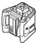
Topn3oHTaIbHbIy
pexum (GRL 500 H/ GRL 500 HV)
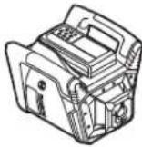
epTKaNbHbI peXHM (GRL 500 HV)
- YCTAHOBITE H3MEpHTeBbHb INHCTpyMeHT B TOpIN3OHTaNB-HOM NIN BEPTKAbHOM NIOXKeHH HA CTA6NtBHOE OCHOBAHHe, MOHTpyTe erHO Ha UtaHB NIN HAcTeHHoe KpeIHeHHe 59c y3nOM BbBepKn.
H3-3a BbICOKO TOnHOCTN HNBENHPoBAHN H3MEpHTeBnBn HNCTpyMeHT peAryPeyET OChEByVBCTBnEBO Ha KOJIeBaHN H3MeHeHH N0NOxEHNN. CNeIte NoTOMy 3a CTa6HbHBM NIOXKeHHM N3MEpHTeBnHO INCTpyMeHTa, YTO6bNCKIIuYtBpepeBbBbBpaBoTe H3-3a DonONHtBnHO HNBENHPoBAHN.
YnpaBHeHne H3MePHTeNbHbIM NHCtpyMeHToM (cm.pnc.c)
H3MePntBbHm HnCTpyMeHT ynpaBnRETCK HONkAMHa na3epHOM npHemNHKe. YnpabNeHHe MOxET OcyuCETBnTcBcnn HENOCpeCTBeHHo Ha H3MePntBbHOM HnCTpyMeHT (na3epHbI npHemHK HaxOJTCB CTAHUN 3apJKN/XPaHEHN6), Hn pni NOMOUs paNOCB3n (Na3epHbI npHemHK CNYKT B KauCeBTe PyNbTa DnCTaHnOHHOro ynpaBnEHnA.
Pa6oune coctoHHa
CnCTema, coCTOaH N3 H3MePHTeBHO HOHTCPyMeHTa Hna- 3epHOro npHeMHnKa, HMeet 3 pa6OuNX COCToHnHa:
-BKIIIOUeHHoe COCTOAHne
Bce cyHKnHm3MepnteHbHO HcHTpyMeHa nNa3epHOro npHeMHNkA kTHBNPOBaHbl.
PnA KTHBPOBAHHO TpeBOXHO CnHnHn3aUNI DnA 3aHTbO T KpaKHa Hn3MepHTeHOM INCTpyMEHTe MrrAet CBeTOND CnHnHn3aUNI DnA 3a-NTbOT KpaKn4.
Bce octaIbHbe HnDnKaTOpbl n Ia3epHbI lyu BblKInoueHb. CnCTema aHTnpeJpa OCTaETCBKnIOueHHoN.

-ⅡIIBbIXOaH3peXIMAmOxNHaHHCHOBaHaKMMTe HaKHONkpyeXIMAmOxNHaHH21.
PexHM OxHdAHn BKNIOaTcA ABTOMaTHueckn, ECnHa IpoTAXeHH 60one 30 MHNy Tnapehbl Npy He nnonaetB npEmHOe OKoUKO 26 Hn Ha IPOTRAeHH 60one 30 MNHT He HAKMAETC HnKAKHX KHOONK HA IaepHom PnemHHke.
Yka3aHHe: EcInnaIa3epHbI npHEmHH K CTpOnTehBbI na-3ep HaxoJATcB Pexmme OxKdAHH 6OJIe 2 Uac., oBa OHn ABToMaTHueCKN BbIKIOUaOTc. IIN BKNIOUeHH Na3epHoro npHEmHHaero HyXHO CHOBa YCTaHOBBt Ha CTAHIO 3apJKN/XpaHEnH6.
BCTaHApTbIx NaCTpoKax 3aBoJa-3nroTOBtTeHa[ФункцЯ рекma OЖиданя DeakTHBnPObaHa].

IaKTHBaunFyHKunpeKmuaOHN daHnOHOBpeMeHHoHaXMaiTe Ha BKIOUeHHOM H3MepHTeBHOM HCHTpMeHTe KHOIKY BKNIOUeHH/HbIKIOUeH N1N KOHNIpypeKmuaOKNaHn21 n npndepknte OK.2c.
HaHcHnnee Ha npoTaeHHn OK.3 c0toB6paKaTaC HOBoe COCTOHHne [fpyHKnnapeKIMa OxNdaHnA kTNbPoBaHa =SLPOn] nHNDaHkToppeKIMa OxNdaHH44.
PnBbIKNoeHmN HAcTpoKa He CoXpaHa-ETcB NAmTn. N3MePntbHbN HcTpy-MENT BcERda 3aNyCKaETcC OTKIOueHHOfHKnepeKIMaOKndaHna.


348|Pycckn

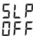

-ДЯOTKJIQUEHINФYHKUNIpeKHMa OXHDAHNAODHOHBPeMeHHO HAXMaJIte HA BKNIOUeHHOM N3MepHTeNBOM HHCTPYMeHTE KHONKY BKNIOUeHHN/BlkNIQeHHN17N KONKYpeKHMaOKINaHH21nPnDEPKITe OK.2c.
HaIncnlee Ha npotraKeHH OK.3 c oToB6paKaTaC HOBoe CoCToHHe [fpyHKnpeKMA OxNdaHnOTKIOUeHa =SLP OFF] INHdkatop pexkmaOxNdaHH 44.
ABTomatuecckoe OTKIOUeyHne
PnOnpeHEnHHbIX yCNOBHX H3MePHTeJIbHbI INHCTpyMeHT nIa3epHbI pNEMHHK OKJIIOUaOTc ABOTMAHTueckn (pe- 3yIbTaT CM. BbIKHOueHe) Ha cTp. 347):
Ha npotrakeHH 60nee 2,5. u. H3meHnTeIbHbH nHCTpyMeHT HaxoITcra 3a npedeNAM duana3OHa cAmOHBeHHPOBaHH N OUn6Ka C COOTBETCTByIOHM KOOM He yCTpaHeHa (cm. YcTpaHeHne HeHCnPabHOcteH), CTp. 357).
-ImMpHteBbHn HcTpymeT npA kTHBPOBaHHoPeKIMME OxHaHHe BkUOaETC B TeueHN 2 lac.
-CnCTema aHTnpeBpa BkIOueHa Ha npOTxHHeHH 60JIe 2.5y.
-Измерпгельнйнсчрментхолntсьнднana30ha pa6oуe TemnepaTybl.
IpeaABTOMaTHueckmOTKIOUeHEmH3MepTeBHOHO HCHTpymEtHa Nla3epHOPO npHemnKa BdoONHeHKe 3BykOBMy CNrHany Ha npToJxHeHH 5 cMraet INNkaTop BixOda 3a npeJebl DonyctmOro TempeyHoro dnaana30Ha 34.
Tocne aBOMaTHueCKOTo TKNIOUeHnA:
-Пи Heo6xOIMOCn IIOJXINTE, NOka H3MePITeNBHINHCTpyMENT Nla3epHybI INPMEHMK CHOBA He BEpyTCBДHaNa3OH pa6oey TeMnepaTypl.
-Пи Heo6xOaHMoCTn 3aHOBO paCNoONKHe H3MePHTeB-HbI INHCTpyMEHT N CHOBA BKNIOHTe erO.
BatapeKa Yacob HCTHHORO BpemeHRTC (Real Time Clock)

Ecnn nocne BkIIOUeHnHa npotJKeHHn 10 cMnaret HNnKATOp INTepBana KaINb6pOBKn 35,3aHTcenaBaTapeKa YacOB NCTHHORo BpeMeHN BCTPOEHnBn AKKyMnyTOp pa3paHnCn. INTepBn KaINb6pOBKn 6oJIbWe He OTCJeKnBaETCn.
-06paTHTecbBaTOp3npoBaHHyIO cepBnCHyIO mactepckyo Bosch.
TpeBokhna CnHnHaN3aunIy IyaunItbI O KpaKn
IpyeynpejckdHnKpaKn CNTeMa H3MePeHTbHOrO HCTpyMeHTa Hna3epHOro PpHemHnKa HMeET Dba MexaHN3Ma 3aunTbI:
-ynpaBnTbH3MePHTeNbHbIM HNCTpyMeHTOM MOXHO TOnbKO pIn NmOoUa3epHOrO pInemHnka; Ha H3MePHTeNBHOM HNCTpyMeHTe HnHaENy npaBHeHH.
BCTaHapTHbIX HAcTpoKax 3aBOda-H3rOToBtEnI [TpeBOxHnA CnHAnH3aunI DnI 3auNTbl OT kpaHn OTKnIO-ueHa].

-ПИЗВКИОУЕНOMИЗМЕРИТЕЛБHOMИСHTPyMeHTe HAKMITE KHOПКу CINHAHIN3aUNI 3aUNITbI OTКраЖN22.
TpeBxHnCnHaHn3aunI nI 3aunIbI OT KpaKJ BkIIOueHa.
HnHKaTOp CnHaHn3aunn Dnna 3aunntbO Tkpaxn 36 NCBToDnO CnHaHn3aunn Dnna 3aunntbO T KpaNX4roprt.
HactpoKa TpeBOXHO CNHaN3aauu Dn 3aunbIOT KpaKn PnBbIKIOeHN COxPAHReTc BnAMrTH.
HOM HHTpyMeHTe KHOJky CnHaUN3aUN DnA 3aunTb ot Kpa-22.
Cnyan npmeneHHn CHrHaHn3aunn nna 3auHTbI or Kpa-
Cnyaui npHMeHHe 3aunTHbI MExaHH3M
N3mepnTeIbHbI IN-CTpyMeT BKNIOUeH.
HNN
N3MepHTenbHbIN HCTpyMeNTBpeXnmeOxndaHn.
TpeBOXHa CnHaJIIN3aIaN aKTHBn-POBaHa

HnKAtop CnHaHn3a- 1nnIaI3aIHTbIOT KpaJN 36CBETTCa.

CBetOnHcHnHa3a- 4 Hn3MePHTbIOT KpaH 4 Hn3MePHTeBtHOM HNCTpyMeHTe MeDHeH0 Mnaet.
H3mepntbHbHnHCTpyMeHTBbIKIOueH.
BbIeHbI npHmHnK BIKIOUeH He HaxoDITcBCTaHcN3aPdKn/XpaHeHn6
TpeBxHnCnHaIIN3aNn DeakTN BnPoBaHa
HINHKaTOp CNHaHn3aunn Dnna 3aunbI OT KpaKn 36 He OTo6paKa-ETcR
CBetoHNOC HrHaHnHaZaUN DnA 3a- UHTbO T KpaKn 4 Ha N3MePHTeB-HOM HNCTpyMeHTe He CBETTC
EcnH3MePHTbHbHnHcTpymEt ydaenTcOaKtyaHbHO To MeCTa HaxoXdEHN pN BkIOueHHo TpeBOxHO CnHaHn3aunDn 3aunTbOt OKpaxn60nee cem Ha 5c,cpabTaBaet TpeBOxHARnHAN3aun:
-3MepHTeIbHbINHCTpyMeHTnHa3epHbINPHEMHK BblDaHO3BYKOBO CNrHaI.
A-B3BeWeHbI yPoBHe b3yKOBOrO daBHeHn O3ByKO BORo CnRHaN a coCTaBnE rdo 110 d5(A),ero HnB3r peryI INPOBaTpeYINPOBkoI rPOMKocTH 6bHuHO 3ByKOBOrO CNrHana.
HeepKHTe na3epHb nphemHK 6nn3ko kxy!rpoM- KIN 3ByK MOKeT NOBpeNTb cnyx.


Pycckn|349
-BceyHKnHObcnyKbAHnB6noKpyoTcA.

-CBToHIOI CNHANH3aUNINJIAaHTbOTKpaHN 4Ha H3MePHTeNBOM HCTpyMeHTe 6blcTPO Mraet.

-HHKaTOp CnHaJIH3aUIN DnH3aUNIbOTKpaJN 36 HaJa3epHom PnEHmHKeMnFAeT.

-ДЯ BBKIOUeHn Cpa6oTabeWc HcHAn3aunn HAKMTe Ha KONky CnHaN3aunn DnAauntbI OT Kpaxn 22.
Ipaa3bkyoBOro cnHana npekpaaaetc.
CHNMAeTc6oKnPoBka co BceX cyHKnY npab-
PnB KIOUeHHN Bce HAcTpoKc6paBaHOTca HA cTaHApTbIbe (CM.《KIOUeHHe》,CTp.347).
TpeBxHnA CnHaIIN3aUy DnI 3aUHTbI OT KpaXn CHOBa aKTHBnPOBaHa.
HnKaTopbI nnpOBepKn KaH6pOBKn (npdeynpeKdEHH HApUeEHN KAn6pOBKn)
Pn Heo6xOdHmocn npOBepKn KaHb6pOBKn H3MepeTbeHo ro HcTpymEtHa OTo6paKaetaCnIe NaepeHOro npHeMHNka Noce BKNIOUeHHa pa3NNUHbIMN HINkATopamB KOM6Hnauu C HNDkATOpom cCAL
Yka3aHHe: Nocne npBpOro 3anycka B kCkIpyatauNo daTnKnnpedynpeKdEHHo HapUweHHN KAnbPobKN (HHTepBaNa KaIbPbOKH, TeMnpeAtpbl XpaehHH, cotpcEHHHN3MePNTeBbHO rHcTpymeHTA) BKIOueHbI.
HaKaMaIe npn OTo6paXaIoEmcr npedynpexKeHHN O HApUyWeHHN KaHbPoBKN Ha KHOkky KaHbPoBKN 25 Ha npOraKeHHN 2 c.
HINHKATOpbI DnI PNOBepKn KaII6pOBKn BHOBB OTo6paTcTOnbKO npN Bo3HNKHOBeHn npHnHbI DnI PpeDynpExKeHnO HApUeHnKaII- 6pOBKn.
PekomeHyembI npaOK deCTBn Iocne coo6eHnO npOBepke KaHH6pOBKn
War cm. ctp.
1ПоверьteTOUHOCrHINBEJIHOBaHn354
2a OTKIOHeHHe Ha 30 M He BixOHTa npe
deIb MaKcMmJIbHO DoNyCTHMbIX 3HaYe
Hn ±3,0 MM:
ckpoTe HnIMKaTOp NpeDyNpExeHn o
HapyuEHn KaIIb6PbKN 349
2b OTKIOHeHHe Ha 30 M BixOHTa IpeDeIb MaKcHMaJIbHO dOnyCTMbIX 3HaueHn ± 3,0MM .. BbINOHNTe KaINbPoBky U3MePHTeIb HNCTpyMeHTa 355
3bПоьерпг TeTOHOCTh HNBeINIpOBAHn 354
4bIocneKaH6pOBKoTKnOHeHHeHa30M HeBbIXoHT3a npdeBbMaKcHMaIbHo doNyCTMbIX 3NaeHn ± 3,0 MM: MoXHOpaObatb63yuepeBaTouHO- CTN.
Iocne KaHbPOBKN OTKNOHeHHe Ha 30 M BCE eue BbIXoND3a npedeBbMaKcHMaNbHO donyCTMbIX 3HaueHH ± 3,0 MM: OdaTe H3MePHTeNBbHmHCTpyMeHt HA npOBepky B cepBCHcyIO MaTepckyIO Bosch
Pexmmblpa60tbl
JHHH OCH X H OCH Y
JIHHH NCHX HOCN YOTMEYeHbHaKOpNyCe HaPotaOnHOHOr TONOBKO.
PotaunOHbIpeXHM
H3MePHTeBbHbI HnCTpyMeHT pa6OaTe C NOcTOrHHoC KcopoCTbIO BpaSeHnra (600 mH-1), npiroHOJ dNr HCNoJIb3OBAHnRAIa3epHOrO npHeMnKa.
0630ppeKHMoB pa60tbl
-ABTOMaTHueckoe HHBeINPObaHne IocJIe BKNIOUeHn/BOBpeM3KCNlyatauHH
- PekHM HAKIOHa B OOnH OCh
-peKIM cpeDneIHHH
-cnctema aHTndpeiΦaADs
-HeHHpeKMMBepTKaJIbHOMpeKHM (GRL500HV)


350|Pycckn
ABTomathueckoe HHBENPOBaHne
ABTomatHueckoe HbBENHPoBaHne Nocne BKNIOeHN
Iocne BkIIOUeHn H3MePeITbHbI HNCTpyMeHT npOBepaTROPHOHTaJIbHOE NOIOKeHHe N ABTOMaTHueCKN BbIPaBHnBaETHEPOBHOCTN B PpeJExA DnaIa3OHa CaMOHBENIOPOBAHHN OK.8,5% (5°).
BoBpemHnBEnIpoBaHNmraet HnDnKaTOp npEpynpExeHNrO HnBeHNpObaHN 37.
GRL 500 HV: H3MepHTeHbHbI HNCTpymEt Nocle BkNIOueHnna camoTcTeBbHO paacno3Haet BEPTKaNbHoe nHrnpO3OHTaBbHO nNOXeHne. IINpepeBOda HNCTpyMeHa Tn rOPI3OHTaBbHO rNOXeHnB BePTKaNbHO eHn HAO6OpOT BbMOxete H3MeHHTb NIOXeHne HNCTpyMeHa, He BbIKIOyra erO.
ABTomatMueckoe HNBenHpoBaHne BO Bpemr 3KcnpyatauHH
Ecnno n3meHnnaOxHn H3mepntbHbHnHcTpyMeHT haoDnTc3a npdeIaMn dana3oHa caMOHBenpoBaHn np6bl.8,5% (5°), aBOMATueckoe cMOHBENPOBaHne HeBO3MOKHO N OTO6paKaTeC KOD OUN6KN (CM.《UcTaPHeHn HeNCnPabNocTe》,CTp.357).
HnBelenpoBaHHb H3MepeHtBbHb HcTpyMeHt NocToHH npoBepaTe CBOe TOpN30HTaJIbHOe NIOXeHHe. Ppi H3MeHeHH NIOXeHHA BTOMaTNUeCKn PPOH3BOJTCa CaMOHBeHNPOBaHHe.Bo H36ExAHHe OUn6Ok H3MepeHHBpaUeHHe na- 3ePHOrO Nyu aPekpaaaeTcB Bo BpeMn HnBelenpoBaHHa.
PexHM HAKHOH B ODHOHOCN
B roHIOHTaIbHOM noIOJKeHHn 3MepeHTeJIbHO nHCTpy MeHTa BpeKHeMa HAKIoHa No ODNHO cN pOnCXoDHT aBTOMaTueckoe HNBENPOBaHne I0OcX.
PiocOCTb BpaUeHHNo MoKHO NOBOpaHbAtb BOKpyr OcN X B npedenax ± 8,5%
Yka3aHHe: PnKeHaHH NaCTPOINb yron HakoHc pca3y noCNE BKNIOUHHe Heo6xOIMN OIOOJDAb 3aBepueHn ABToMaTHueCKTO HNBENPOBaHH (CM. ABOtomauHcckoe HNBENPOBaHHe NOcNE BKNIOUeHn), CTP. 350). OHO IpeDtBpaIuaet HenpabInbHbIe pe3yNbTaTb H3MepeHH.
Hacrpoika yrna hakloha
HactpoKa yrna haknoHa BO3MOxHa B npedex ±8,5%.

HaKMMte HepKHTe HaxaTOn KhoNky HAKHOHA 18 Nn 20, Noka Ha DnCnnee He OTo6pa3ntcHne6xOdHMoe 3HaueHHe HAKNoHa.

OTnIyCTnTe KHOHnIKy HaKJIHOHa 18 Hnn 20.
BoBpMaHactpoKnYrnaHaKnHOHaMira- et HINIKaTOp npdeynpeXeHnO HnBeNIpOBaHH 37.

HINKATOPpeXIMHaHaJIHOHa 41 CBeTNTCA.

- OndoBpeMeHHo HaxMHTe KHOKNy HAKIOHa 18 n 20.
HacTpoKa yrna HakNoHa DeaKTHBnPOBaHa. BkIOuAeTcra ABTomaTHueCKoe HbENIpOBAHne (CM. ABTOMaTHueCKoe HbENIpOBAHne), CTP. 349).


PnBbIXOe3a npdeIbI dHana3oH hAknHOa B±8,5% HnHnKaTOppeKIMHa HAcToPOKn YrNa HAKNoHa 41 RaChET N OTo6paKaETcKOd OUn6KN (CM.《YcTaPaHHe HEnCnPaBHOctE》,CTp.357).
peKHM cpeHneJHHHH (cm. pnc.D)
BpeKHe CpeHn HnHHn H3MePeHteNbHbHn HnCTpyMeHT aB TOMaTHueCKn IbTaTeCn HaHTN CpeHIO NnHHIO Na3epHO npHmHKa, ONyckar NODHMma POtaUOHHyr OJONBky.

HaKIMaTe Ha KhoNky peKIMa cpeHneiHHn 19ok.2c.
BknioaetcAABTOMaHueckoe DBNKHeHne potaIOHOHOIPOBKBN BBepx INBn3.
Понск:
- PotaunHna ronOBKa nDnHMaetcB Bepx do ynpa.
2.BkIIOUaTeTcIa3eRbHbI Lyu.
3.PotaunOHnraTolOBKaOnyckaetcBnH3.
4a. Na3epHbI Nuy nonaTaet B npHeMHOE OKoIKO 26 Haxo-NT CpeHIOIINHIO.
HNN
4b. Na3epnbl nyu He haoonB dnaana3ohe nepemeuen npneHmoe okoKo; OTo6paJaaetcKoOOn6Kn (CM. YcTaPHeHne HncnpaBnOte》,Ctp. 357).
BoBpemnONCKa CpeDneHmHHMnFAe HnDnKaTOp npEpynpExeHnO HnBeHNPOBaHHN 37.
INHnKaTOppeKHa CpeDHeI HnHn 42 CBETTCRA.
CMOMeHTa nonapaHnnaepHoro lyuBa B pInMeHHe OKOUsKo 26 Ndo MOMeHTa HaXOXKeHncreDneHnnPa3daTcra CTpeKoyuyn3Byk.
PnnoaHnnaepHoroLyuBaBnpHmHoeOko26 CKoPoCTb DBNKeHHPOtaUHOHHoTfONOBKnTOPMO3NTcR.
Iocne 6bnapykeHHcpeHn HmHHn HmMeHtBbHn HCTpyMeHT ABTomaTHueCKN BbIKIOHaET peKHM CpeHHe NHH. HaCtpoEHbH yrOHa KaHOHa CoXpaHReTcB nMaTn OTo6paKaetcHa Hncnlee.

-ITRAOTMeHbIpeKIMaCpeDHeNINHNBOBPEMa NONCKA HAXMITE KHOIPKpeKIMa CpeDHeN INHN19.
HNN
1609 92A4DX|(28.3.18)BoschPowerTools


Pycckn|351

Auto


HaKMITE OJHOBpeMeHNO KHOKN HAKOHA 18 H 20, Yo6bI BJIIOHTb aBTOMaTHueCKoe HHBENPOBaHHe.
Yckopene noncKa cpeHne HHHn NaepHoro npHemHka
PonckcpedneHHnHnna3epHoro nphemnka Bcerda haHnHaetcndBnKHePOaunHOHOrrOBOBKn BBepx.EcnIa3epHybIyuHaxoJITcNDcpedneHHnHneN eue He nonanB pnhmHoe OKoUko na3epHoro nphemnka, DBKHeNe Ia3epHoro Lyya moKHO pa3BepHyb B o6paTHyo CTOPOHy.

-HaKHMaTe Ha KhoNky peKMa cpeHneIINHH 19ok.2c.
BknIouaetcraabTOMaTHueckoeDBHXeHne poTaIOHHHOIIOBKNBBepxHNBH3.
-HaKMITE KHOKY HaKIOHa 20.
Potaunohna tonobka onyckaetcBn3.
CHCTema aHTnpeiFa ADS
H3MePHTbHbI HNCTpyMeHOTcAaHcTeMoAHNTpeHpa, KOtOpA pIe H3MeHeHH NIOJKeHH, COTpcEHHX H3-MepHTbHOrO HNCTpyMeHTa H Bn6paHHrpyHTa PpeoTbpa-aaet CamOHBeHNpOBaHHe Ha HOBo Bicote H, TaKHM Obpa3OM, Own6Kn Bbcotbl.

CnCTema aHTnDpeFpa BkIIOuAeTc npBn. Upees 30 c nOcne BkIIOUeHn H3MePHTeBHO rHCTpyMeHTa.
Bnpoece BkIOUeHn HNdkaTOp nppeynpejxHe HnO oCOTpaeHnx 38 MeIeHNO Mnaet. Iocne BkIOUeHn HNdkaTOp CBeNTc HnpepbHBHM CBETOM.
CnCTema aHTnDpeHcpa6aTbBaet npn H3MeHenHH BepTNKaNbHO rnoN0KeHHe N3MePnteBHO HcTpyMeHTa Hn npn pereHctpaun CNbHO rcoTpcEHH: BpaueHne Na3epa npekpaaaetca Hmraet HndkaTop PnpdynpckdHnO cTpcEHHX 38. DOnoHnTeBHO na3epHbI npnemHK BteeHHN 5 Cn3daet cTpeKouyUn 3BykoBo CnHaJ.

-Писработавше систemeаHTIпдрфаHaJxMITE KOPOTKO Ha KHOIIky BKJIQUeHr/ByIKIOueHn17.
BKnIOuayTcA ABTomaTHueeCKoe HNBENIPOBaHne (CM.《ABTomaTHueeCKoe HNBENIPOBaHne BO BpeM 3KcNpyTaunH, cTp. 350).
-ПоверьтБусOTиЯзEpHOrOууа no peHepHToTouke n npH Heo6xOIMOCnI NOkOppeKTHpyTe BbICOTy I3MepHTeNbHOrO INCHTpymeHTa.
BbIKIOUeHHe cHTeMbI aHTNdpEhFa
CnCTemy aHTNIDpeHpaMOXHO BbIKHOHTb BO Bpempa6oTbI 3MePHTeJIbHOrO INCHPTyMeHtA.

-HaKMTe KhoIky BkIIOueHn1BbIKIOueHn17. CnCTema aHTINpeHa BaBkIIOueHa. HnIkaTOp npEynpeKeHnO cOTpRceHHx 38 60nbWe He oTo6paKaetc.
PnBbKIOUeHn HAcToPiKa He CoXpaHaTeC T BNaMTrn. PpB KINIOUeHN N3MePeHTeNbHO INCTpyMeHTa CCHTeMa aHTNdpEpa BcERda AKTHBnPoBaHa.
JIHHeHbIpeXHM B BepTHKaIbHOMpeXHMe (GRL 500 HV)
BBeTpHKaIbHOM NIOXKeHHN3MpTeJIbHO HHTcPymHaTnIOCKOCTb BpaUeHHN MoXHO YCTaHO BTOBbD0N X DnYnpoHHe COOCHOTnn NapaJIeHBO HO BpABHBaHn.

-ДЯ NOBOPOta NnCKoCTN BpaueHnno YacoBOI CTpeJIke HAXMITE KHOKNy HAKNoHa 18,ДЯ NOBOPOta IpoTHB YacoBOI CTpeJIKN -Ha KHOKNy HAKNoHa 20.

HactpoKaIonoKHeNBA03MoKHaBnpedax ± 8,5%
PotaHnHa rOIOBkA HauHHeT MeDHeHbpeaTcra, noCTeHnHO ha6pap o6opotbl.
PexHm cpeHn Hnnn npn HneHOM pexHMe (cm.pnc.E)
B pexnme cpeHne nHHn n3MepeHntbHb HnCTpymert ATOMaTHueeCKN uET cpeHIO IO NHNIO na3epHOrO pHnEMHnKa, nepeMea a poTuONHHy roIOnBky BnpBO n BnEO.

-HaKImaTe Ha KhoNky peKIma CpeDHeiHnHH 19ok.2c.
HaHnHaetcABTomaTneckoe nepemeuehenpeotaHOHHoIgOBKn BnpaBO nBNEBO.
ПОИСК:
1.PotaunHnaTOnOBKaNoBopauHbAeTcDo ynpaBnPaBO.
2.Bkniouaetcna3epnlyu.
3.PotaHnHaI rONoBkA noBOpaunBaetc BneBO.
4a. Na3epHbI Nyu nonaTaET B npHeMHOe OKoUKO 26 HaxOHT CpeHIOIINHIO.
#
4b. Na3epHbI Nyu He HaxoHT B Dnana3OHe nepemeueHn nphemoe OKoKo; OTO6paKaetcKOd OOn6Kn (CM.《YctpaHne HEnCnpaBHOcte》,cTp.357).
BoBpemnnoncAcpedneHmHHMnFAe HnHnKaTOpnpdynpeKdEHHOHNBnPobAHN37.
HINKAtoppeKMa cpeHnNn42 CBETTCRA.
CMOMeHTa nonapdHnnaepHOro lyuBaB pInMeHHO 0KOUko 26Ndo MOMeHTa HoxKDeHHn CpeDneHnn Pa3daTcra CTpeKoyuyn3Byk.
Pn npanaannaaepno nyuB npneHmoe OKOwko 26 CKoPoCTb DnKHeHPOtaUHOHNOLOBKn TOPMOHTCn.

352 | Pycckn
Iocne 6hApyKeHHn CpeHHei HHHn N3MePeHTbHbN HCTpyMeHT ABOTMaTHueCKN OTKIOuAeT peKHM CpeHHei HHHN.

-ДЯ OTMeHbI pexNIMa CpeHneIINHH BO BpEmrNONCKa HaxMITE KHOIIky peXnIMa CpeHneIINHH19.
HNN

HaKMnTe OJHOBpeMeHNO KHOJIKN HAKOHa 18 N 20, Yo6bl BKNOHHTb aBTOMaTHueCKoe HNBENHPOBaHHe.
Auto


YckopeHne noncKa cpeHne HHHn Na3epHoro npHemnKa
PonckcpedneHHnHnna3epHoro nphemnka Bcerda HauHaetcCdbXeHnpoaHOnHO roNoBKnBnpBO.Ecnna3epHyIyHaxoNDTCNEBaOT cpedneHHnH nEe He NoanB pHemHoe OKoWko na3epHoro npHemnKa,DbXKeHne na3epHoro LyuMoXHo pa3BepyTb B o6paTHyo cToPOhy.

-HaKHMaTe Ha KhoNky peKHMa cpeHne HINHH 19 OK.2c.
PotaHnHa rOIOBka aBTOMaTHueCKn nepemEaTcBnPaBO.
-HaKMTe KHOky HaKIOHa 20.
PotaunOHnraIOnOBKaOnyckaETcBn3.

Hndkatop OTHOCHTenbHOBI BBICOTbl (cm.pnc.F)
+30.0mm
PacctoHne MeJy IIOCKOCTbIO BpaIe HnHcpeHne NHHe OTObpaXaETcHa DnCIIeB KaucctBe a6COJIOTHOB BENHHy (B [MM] nnn [dIOHmax]).
CM. TAKKe «HactpoNka HNdkaTopa eHnUcbln3MepeHnA», cTp. 356.
Pa6oTa cIa3epHbIM npHeMHKOM
HaxoHaeHHa3epHoroIyua npn H3MepeHHxHaOTKpbTOMB03dyXeHHa60buxpacCTOHHxBHHTPNOMeHHeHCNoB3yTeNa3epHbI pHemHHK.
-PacnoJIOXHTe na3epHbI npHemHK TAK, YTO6bl na3epHbI NuyMOR nonactb B pHemHOE OKOuKO 26.
PAnocB3b MExky H3MePHTenbHbIM HnCTpyMeHtOM n nybTom dctaHnOHHO ynpabneHa/na3epbIM npHeMHKOM
BcoTBeCTBnC hAcTPOKaMn 3aObda-N3rTOBnteNa3epHb npHeMHK LR 50 no6ecnpoBOHOMy coeHHENHO pa-6oTaET B KauCTBe NybTa DNCTAHUHNO HOrO ynpabNeHnN3MePHTeNbHO INCTpyMeHa.

-0To6paKaTeTcHnHkKatop padnoocB3N 33,060-3Haayoouy,UTo na3epHy npHemHK CTaIpybTom dntcaHtouHO ynpabHeHH.
Kn3MepnteBHOmy HNCTpymEny MOKHO NOKIOHHTb HeCKoIbKO Ia3epbIX npEmHHKOB LR 50.
-BbIKIOHTe H3MePHTeHbHbINHCTpyMeHT INa3epHbINpIeMHNK.
- YctaHOBHTeDOnONHInTeIbHbI Ja3epHbI pINEmHHK Ha CTaHcIO 3apAKn/xpaHeHn6.

-HaKMITE KhoNkIy BKIOUeHnA\BbIKIOUeHnA 17.

-0To6paXaetcHnHnKatop padnoCBA3H 33,0603Haayaou,yToIaepHbI npHemHK cTaNyblTomDCTaHIOHOYnpaBHeHH.
-CHHMMTE Na3epHbI pHemHHK CO cTaHcHn 3apAKn/XPaHeHn. Pocne 3TOrO, YTO6bI BKIOUHTb N3MePnteBbHbINHCTpyMeHT, Bam HyXHO B TeueHne 30 MmHy TaKaTb HaKHONKY BkIOUeHn/BBkIOUeHn 17.
Yka3aHHe: EcnN KOHOMy H3MePHTeNBOMy HnCTpyMeHTy NOKIIouaeTc HecKoJIbKO Na3epBHX PnHEMHNKOB, NocneHnn NoKIIoueHHb N3epHBn PnEHMK FyHKUHOHyET B KaueCTBe NylbTa NCTAHNoHHOR ynpabNeHn.
OctaIbHbIe Ia3epHbIe PnEHMNKn ABNIOCTc HCKNIOHTeBHO Ia3epHbIMn PnEHMNKaMn.
TakHe NaKCTPOKn, KaK ToHOCb N3MepeHn Hm 3ByKOBoi CnHnA,IaI KaKDoRo Na3epHOro PnpEHMNka MoTy HacTpAnBaTbCnHnBnDyalbHO.
PnBbIKIyehHnIa3epHO npHEHnKa, BblONHIOUeO cyHKuHIO NybTa DnCTaHcHOnHHo UynpAbeHn, BbkIIouaETc TaKke NImepHTeNbHbN HnCTpyMeHT. KaxDb IOnOHTeNbHbN Ia3epHbN pHeMHNK HyXHo BblIOvAtb OTdEhHO.

EcHpaNOCB3b nppeBaNaCb,doonHHTeNbHO K 3ByKOBOmy CnHaNy MnaeTnDnKaTOp paNOCB3n 33.
3To 03Haayet, yTo INDnKaTOpbI npEnynpExeHnna (Hanp. o KpaKe, aHTnpeJe, KaIN6PobKe) 6oBbIe He OTO6paKaIOrTa nIcTaHUNHO ynpaBnTa H3MePntEhBbIM HNCTyMeHtOM HeBO3MOxHO.
Yka3aHHe: PekmOxNdaHnN 3MepntbHOro HcTpyMeHTa MoXHO aKTHBnPOBaT b NdeAKTHBnPOBaT ToIbKO NyTeM HkaT HKnONk peKIMa OxNdaHn21 Ha na3epHom pHemHHKe, BblONHnHOe MfHKnIO nIbTa dNctAHNoHHORo ynpablenHH.
HactpoKa 3ByKOBOrO chrHa/tpoMKoCTn
InonadaHne na3epHoro lyuBa B npHemHOe OKoIko 26 MoKeT COPOBOXdaTbC3ByKObBIM CNHaNoM.
BbMoKeTe Bb6paTb OINH IN3 DByx ypoBHe rPOMKoCTH NnN OTKIOUHTb 3BYK.
BCTaHapTHbIX HAcTpoKax 3aBOda N3rTOBNTEny Bb6paH [HOpMaIbHbI 3ByKOBo CnHAn].

-HaKIMaTe KHOKNy 3bYKOBOrO CnHana/ rPOMKOCTN 24doTexnop, nKaHe NOnyUHTe XeNae-Myo HAcTPOkY.
HINIKATOP He OTo6paetc: 3BykoBoI CHTHaJI BbIKIOUeH

HopMaJIbHbI 3ByKOBoCnHaI
rpoMkn3bYkoBOcnHnHa


Pycckn|353
PnBbIKIOeHnHnHAcTpOKa3ByKOBOrOcHHa/rgomKocTH COxpaHReTcBnAMTu.
Bb6op hactpoKn HnHkKatopa cpeHei HmHm
BbMoKeTe 3aTaB, cKaKoToHocTbIO NOnOKeHne Na3epHoTo Nyaa Byet OTo6paKaTbC B npHeMHom OKoUke KaK «No UeHTpy'.
BCTaHApTbIbX HAcToPoiKaX 3aObOa-N3ROTOBtEna HAcTpoEHa[《CpeHn/3MMTOUHOCTbN3MepeHH]

-Hakmaite KhoIky HactpoKn TocHoCTN H3mepeHn 23 Do Tex nop, noka He IONYHTe Xenaemyo HactpoKy.
IpHmepHaDcnnee OTo6paKaAeTcra ToOHOCTb H3-MepEHNA《TOUHAR HAcTpoKa》/《CpeDNHAR NaHACTPOKa》/《rpybaHAcTPOKa》NTOHoe 3NaueHHe.
PnBbIKIOueHHHAcTpoKaTOUHOCTN3MepeHHaCOXpAHETCRBnAMTH.
HnHKaTopbHaPapBneHn
Ponokene naepnoro nyuBa npiemHom OKoWke 26 oTo-6paxaetca:
HaHcNnEe 15 cInueBoH nTbIbHOH CTOpOH bIa3epHOro
PnEMHHKa pN NOMOUI INHdNKATOPA HnPaPBNEHn Ia3
3epHbI Ny HAD cpDEHn IINHeN 39, INHdNKATOPa HnPABNEHn Ia3epHbI Ny npD cpDEHn IINHeN 40 Hn
HNDKATOPa CpeHE NINHn 43.
-ONUHOHaBHO npn NOMOu 3ByKOBOrCnHaHa.
Ja3epHbI npHEMHK pacnoJoxKe cHuskOM H3KO:ecnIa3epHbI Nynpaadet B BepxHOO qactb npHEMOHOOKUka 26,3a0apetcra HNdkatop AnpabNEHnAe3epHbI NyuHn cpedne NINHe" 39 nNoONKTeBHOe 3aHaeHHe INDKATopa OTHCHTbHO BBcTob3 12 NOKa3bBaet, HACKoJIbKO HNYHXO NEpeMECTNb Ja3epHbI pHEMHK BBEXP.
PnBKNIOUeHOM3BYKOBOMCHRHaNECHRHaNIOJaETCmEJIeHHbIM HHTEPBAJOM.
-CDBnHbTe na3epHbI npEmHHK B happABHeHH CtpEKN BBepx.Pn np6nHexHH K cHTpaBHO MapKpOBKe 16 OT HdkaTopa HanpABHeHH 39 OCTaETC TOnkko KOHNK
Ja3epHbI npHeMHK paCNoJXeH CnHxkOM BbICoKo:
ecnna3epHbI Nyu nonaAet B HxKHOU qactb npneMHoro OKoUKA 26, 3a0paeTcra HNkAtop HappaBHeHRA (na3epHbI NuynpCpeDHeHnnHRe)40HOTpuaTeNbE3auHeHNE HNKaTopa OTHOCHTbHOB BICOTb 32 NOKa3bBaet, HACKOB KHyHXo NepeMeCTNb na3epHbI npneMHNK BH3. PnBKnOueHON 3ByKOBOm CnHane CNHAn NOaTeCn C bI-CTpbIM INTEpBAOM.
- Cdbnhte naepnbI npemHnK B HanpaBneHn ctpkn Bn3. Pn npbIbnKeHH K ceHtpaBHOH MapkpOBke 16 OT HdkatopA HanpaBneHH 40 OCTaETC TOnbKO KOHNK.
Ja3epHbI npHemHHK no eHTpy: ecnnaeepHbI Lyu nonaTaE TB npeMHoe OKoUko 26 Ha yPoBHe cHTpaJIbHOI MapKnPOBKN 16, OTo6paKaTeC HmIKaTOp CpeDHe IINHN 43. PIn BKLIOueHHOM 3ByKObOM CnHaIe NODaTeC HENpePbIBHbI CNHAn.
Pn CMeueHn H3MepntbHOro HHCTpyMeHTa N BbIXOe na3epHOro lyu 3a npdeIb npemHOrO OKUka 26 B TeeyHe np6bl.5 CMraetnoeHn OTo6paKeHHb INHdkatop Ha npabEnH 39 nnn 40.
3aunTHa yHKnur Strobe ShieldTM
Ja3epHbI npHemHHcOchaueH 3JKeKToHHbIMn HnBtPamm dIra Ctpo60ckONOB. HNtBtpb 3aunuAOT, Hanp., OT HeCnPaBHOCTe, Bb3bBaEMbIX np6neckOBbIMn MaqKAMN CTPONTJIbHbIX MaUHH.
HaheceHHe OTMeTKn
C NOMOJIbIeHTpaJIbHm MapKIpOBKn 16 cIpaBa n CneBa Ha NaIaIepHOM pIphEMNKe MOXHO OTMeuATb BblcOTy NaIaePHoRToIyua, KOrDa OH IpoXoJIT CheE3 CEHT pIphEMHOrO OKUka 26.
PnHaHeCenHOTMeKn CneHTe 3a Tem, YTO6bI N3MepnteB HbN INCTpyMeHT PaCNoIaFAnC TcPO BePTKaIbHO (PnP ROpN3OHTaIbHOM Na3epHOM Lyue) INCTPO TcPO ROpN3OHTaIbHO (PnP BeTKeAIBHom Na3epHOM Lyue), INaue MapKnpoBka 6byT CmEeHa No OTHoWeHIO KNa3epHOMy Lyu.
Iopcbetka dncnner
BCTaHApTbIhNHaCtpoKkax3aOba-H3rTOBHTeJI [noCBETKaDnCnnerakTHBnPOBaHa].
EcnB TeueHne OK.30c.He HaxnMaetc HnKaKx KHOIOK, NOCBETKa DCNPIe OTKnIOuayTcR.
PnnaHaaTHNIO60KNHOKNHINpniNoaAHnNAzepHOrO LyuB PIneMHOOKoUKOIOcBeTKaDcPiE CHOBBAKHO- qaETCA.

-ⅡIaBbKIOUeHnNOcBcTKINCnnerOHOHBpeMeHHo HaxKMITE KHOKNy BkIOUeHn/BbIKIOUeHn17NKHONK3BYKOBOrO CnHa/rgomKocTn24.
PnBbIKIOueHn HAcTpoHka NODCBETKN DnCnner COxpaHr ETCBnAMrTH.
3aKpennneHn c nOmoBIO depKaTeIaNbHOMePHo peKN (cm.pnc.G)
C NOMOUIbEO depKataIaNbHOMepHO peKn53 na3epHbI pNEMHNKOHXO yCTaHABINBaT KaK HaJaBHOmePHo peKe CTPOHTeBHO rna3epa 55 (pNaHdJIeXHoCTb), TaK nHa dpynx BCNOrAteIbHbIX npcNoocbeHnrx HInpHOndo 65 MM.
-ПлOTHOPnKpyTHTe BbIDBnKHyOpaMy 58 npn NOMOu KpeNEXHO BRHTa 56 KdepKaTeIO daNbHOMeHoi peiKN 53.
- Ocnab6te pKNCpuyuui BNHT 54, HadeHbTeepkataeB daNbHOMepHO peKN, HAp., Ha daNbHOMepHyIO peKy CTPONTbHO rO Na3epa 55, H CHOBa Tyo 3akpyTne KpeNekHBnHT 54.
-Пи nOMOUI BATEPnac57 DepeKATeB daNBHOmeHPOH peKN53 MoXHO BbIPOBHrTb NO TOpN3oHTaIN. HepOBHO yCTaHOBHeHHb N3MePHTeBbHn HnCTpyMeHT DaET HeBEPbIe NOKa3AHn.
- BCTaBbTe Ia3ePbH II pIneHMNK B BbIDBHXHyO paMy 58.


354|Pycckn
KoHTpOnb ToUHOCTn H3MepHTenbHOro HHCTpyMeHTa
Cnedyuohne paobtbpaaetcBbINONHrTb TOnbKO KBAHnΦnnpoabHHbIM NobyehhBMnIaM. PpABHa npOBeHnKOHTpOJIaTOUHOCTNIII KANbPoBKn I3MepeNTbHO rHCTpyMeHTA D0JXHb6bITb3BecTHbl.
ΦaKTOpblBnHbOuHe HaTOUHOctb
Ha6b0nbuee BnHnHHe Ha ToUHOCTb OKa3bIbaET OkpykaOuaa Temepatypa. B Ooc6eHHoCTn N3MeHeHHa TemepatypbI no Mepe ydaeneHHa OT rpyHTa MOry T Bbi3bIbTa bOTKIOHeHHa na- 3epHoro lyuA.
Hapdy C BHeuHHMBO3DeIeCTBnHM TaKke N CteuΦnueCKne IIN HcTpyMeHTa BO3DeIeCTBnR (KaK HAp.. NaEHNn CHbHbYe yApbl) MOrTy PnIBoNDtB K OTKIOHeHnM. TOMy BcERda NepeH naAion paOboti npOBepaTe KaNb6pobKy.
OTKIOHEHNACTAHOBATCA3aMeTHbHaauHHaCINHBiI3MepnTeBHOrOyuaCTKaB20MNMOrTpnpDInHe100MBo3paCTuB-4pa3aNo cpaBHeHIOcOTKIOHEHMAhyacTKe 20M.
Nockonbky npepnad Tempepatpyb hahbonee OuyTM B6HIN3IpyHTA,TO Ha yuaCTkax DHHHO CBBIE 20 M H3MePHTBHBn HHCTpymENT CLEyET YCTaHABINBaTb HA TATNB. Kpome TORO,YCTaHABINBAte H3MePHTeBHBn HHCTpymENT,NO BO3MOXHOCTN,BCEpeHNHe pa6oeyPiOnaAdn.
B cnyuae, ecn H3mepnteIbHbI IHCTpyMeHT npn OndHO nOHNcaHHbIX HNKe InpOBEPOK IpeBcHNT MAKCMaJIbHOE OTKNOHeHne, (cm. KAn6pOBKa H3mepTeIbHoro IHCTpyMeHT Ta), ctp. 355), otdaTe H3mepTeIbHbI IHCTpyMeHT Ha npOBepky B cepBCHyIO MaTepcKyIO Bosch.
IpoBepKa ToHocTH HHBENPOBaHH B TOpN3OHTaNbHOM NONOKeHH
Длпроверкптpe6уетсьбогды учacкн Ha TBepdOM OCHOBAHIMDINHOI30MnepeCteHOB.БblOJKHbBbINOHHTbNOHbIzKlnN3MepeHnIyKaKdoH3DbYoxceN Y.Y.
-3aKpENHe I3MePteIbHbI HNCTpyMENT BROP3OHTaIb-HOM NONOKeHHHa paCtOAHH 30 MToPob O TcEHbHa UTAHBe HIN yCTaHOBtE eRo HA npOuHoe,POBHOe OCHOBAHne.BKIOUHTe I3MePteIbHbI HNCTpyMENT.
-OTMeTbTe NO OKOHuaHHH HBeINPObaHHa CEpeDnHy na3epHOrO JyHa Ha CTHe (TOyKa 1).
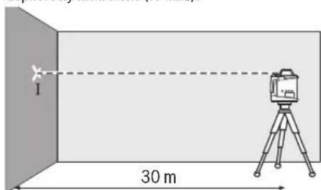
-NoBepHnTe H3MePHTeIbHbI INHCTpyMeHt Ha 180°,noOJXHTe OKOHuaHH erO cAMOHBeINPOBaHH n OTMeTbeCepeHNHy na3epHoroIyua HA CTHe (TOUka II).CneHrTe 3aTEM, YTO6bI TOUka II HaxoDInacb KaK MoxHO 6Oone OTBeCHO HAD TOUKO I IIN NOI HeI.
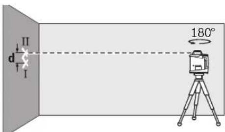
PacctoHHeMeKJyDByM O60HaueHHbIMTOUcKaMnI I HA CTeHe OTo6paxaet paKTNUeCKoe OTKNHOHe H3MePHTeNbHO INCTpyMeHTA NO BbcOTdN H3MepeReMoO OCH.
NOBTOPHTI pOucec H3MepHnA DnIpyro OcN. DnI 3TO TIOBEPHTI N3MEpTeNbHbI INHCTpyMeHT NpeD HauaON H3-MepeHHa 90°
Ha yactke 30 M MaKcMaIbHO dOnyCTHmoe OTKnIOHeHne coCTaBnEeT:
30M× ± 0,1MM /M = ± 3,0MM.
TaKHM o6pa3oM, pa3Hnua d Mekdy ToKamm I I He DonkHa npBbIaTb pN KaKdOM HDByX H3MepeHn 6 MM.
IpoBepka TOUHOCT HNBENPOBAHNA B BEPTHKaNbHOM NOJKeHH (GRL 500 HV)
I npOBepKn Tpebyetc CBO6OHyb OTe3OK Ha TBepdOM OCHOBAHn Npeed CTeOH BlicOTOn 10 M. 3aKpenHe Ha CTeHe UHyp OTBeca.
MoHTpyTe H3MePHTeNBHbI INHCTpyMeHT B BEpTHKaJIb-HOM IIOLOXKeHHN B6JIIN3 CTeHb HA WITATNBHe NIN YCTaHOBnTe erO Ha IPOVHoe, POBHOe OCHOBaHHe. BKIOUHTe H3MePHTeNBHbI INHCTpyMeHT NIOOXJNTe OKOHaHn CaMOHNBeIHPoBAHn.
- HactpoTe H3MePHTbHb HNCTpyMENTaK, UTO6bI na3epHbI NyTu TOHO nOanlan B cepeHNHy hHypa OTBeca HaBepxHem erO KOHcpe. Pa3noctb d MeJy na3epbHbIM nyom HcepeINHO uHypa OTBeCA Ha HnKHeM erO KOHcpe npedCTabnreT cobO oTKIOHeHne H3MePHTbHOro HNCTpyMENTaOT BePTNKaJI.
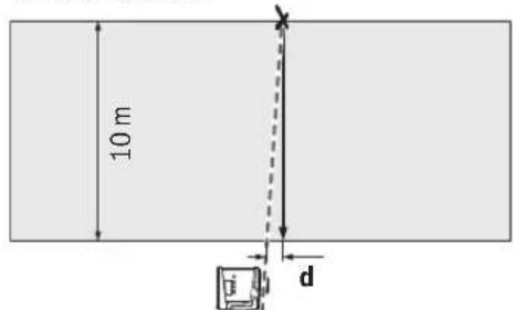
Ha yuaCTke BbICOTOn 10 M MaKcHMaJIbHo DoIyCTHMoe OTKnOHeHHe COCTaBnEeT:
10Mx±0,1MM/M=±1MM.
Takm 6pa30m, pa3Hua d He doJxHa npebbiTa b 1 MM.


Pycckn|355
KaH6poBka H3MepeHTeNbHO HHCTpyMeNTa
CnedyuonpeabopaaetcbBbINONHtBToNkoKbainnphiunpoaHHbIM N06yehhBMnIiam.PpAInna npoBeHnKoHTPOJI TOOHOCTNNKANHbOPKBKN3MePHTeBHOHOHCTpymEHTaONXHb6bTbN3BcETHb.
TuaTeNbHoe KaHb6pyte H3MepeHTeNbHbH NcHCTymENT HnOtdaTe erHa npoBepky B cepBcHcyo MaCtePckyIO Bosch. HeToUHra KaHb6pOBKa Beet K HenpaBnblHbIM pe3yIbTaTAM H3MepeHn.
HaunhaTe KaHb6PbKBy, TOnbKO ecn Heo6xOdmo BbIOINHTb KaHb6PbKBy H3MePteBbHOrO HHCTpyMeH Ta. KaTolbKO H3MePteBbHbI HNCTpyMeH TnepeXoJNT B peXHM KaHb6PbKBr, Heo6xOdmo a6conlHO TOUHO BblONHHb KaHb6PbKBy DO KOHua, YTO6bI B DaJIbHeIeM He NONYuHTb HEnpaBnBhble pe3yNbTaTb H3MepeHNA.
YkaaHHe: Pocle KaIINbPbKn HINHkATOpbl npOBepKn KaIIb6PbKN BHOBB OTo6paKaHOTc TOnbKO B TOM Cnyae,ecnn CHOBA Bo3HNKHeT pNnHa dJa IpeynpExeHnO HApyeHHn KaIIb6PbKn.
ДякалнбpoBKN BamNotpe6yeTc CBO6OJHbN 3MepHTeNBHy yUaTOK Ha TBePOM OCHOBAH NINHOH MHHyM 30 MnepeDPOBHONCTEOH.
Bcerda npoBoOnHe kaIb6pOky no BcEm oCm (GRL 500 H: no ocN X nY; GRL 500 HV: no ocN X, Y nZ).
Kann6pObKa no oCn X
- YctaHOBHTe N3MepntbHbH INHCTpyMeHT B rOpH0HTaHbHOM IIOJOKeHH Ha 7tATMBe 63 (pNHaNDexKHOCTb).
- YctaHOBHTe WtATNB Ha pactoHH 30 M ot CTehb.Ipn ATOM BblbHbI HA H3MePHTeHbHOM HHCTpyMeHTe HNDKA- TOP OCH XdoJIKeH 6bITb paONIOKeH nepneHKnYpHNO K CTHe.
BkIIOUHTeH3MePHTeNbHbI INHCTyMeHT.

-OhOBpeMeHO HAKHMaIte KHOHKy KaNINb6pOBKN 25 N KOHNky HAKNoHa 18 Ha npOTraKeHHn OK.2c.

HaHnCnnee OTObpaKaTaCnMBoN KaHb6pOBKn oocX.

BoBpEMABTOMaTHueCKOro HnBeIINPOBaHnMnraeHTNmKaTOp PpeDynpExdHnO HnBeIINPOBaHH 37.
-NooKdnte, noka n3MepeHtBhBn HNcTpymENT He npOn3BeTeT cMOHNbENIpOBaHne.
HaHnIte npn NMOUINa3epHoro nPnHmHKcpeHIOKnHIO INnepeHeCHTe BbICOTy cpeHNeIHNHINX1HaCTHy.
-Повернente Измерпелбий Иструмент Ha 180°, He MeHЯ BHCOTU WtATnBa.
-NoOxKHTe, NOKa HNdkatop PnpEpyPpExHnO HNBepoBaHH 37 He npecTaHET MmraTb H3MepeHtBhl HCTpyMENT He ppon3BeDeT CaMOHNBeHNPoBaHne.
-HaHnIte npn NOMOuN na3epHOro npneMHnKa cpeHIOU nHHIO npeHecTe HOByIO BbICOTy cpeHNe IINHN «X2» Ha CTeHy.
- OnpeDenHte ToUHyTo cepeDnHy Mekdy CpeHNMM NINHHM NX1N X2N paCNOxKHe Ha Hei Na3epHbI npHemHK C cHTpaBHO MapKnPOBKO 16.


HaKaHMaIte Ha KHOIIy KaHIOHa 18 HnN 20 Do Tex nop, noka He 3aoropTc INHnKatOp cpeHne nnHn43. Pn BKnIOueHHOM 3ByKObOM CNHane NOdaETCn HenpepbIBh CnHnA.
Haxmte Ha KHONky KaHbPOBKN 25, UTo6bl coXpaHHTb KaHbPOBKY B naMRTN.
HaHnCnnee oTo6pa3HTc CmBbON OKoHuaHHa KaHbPobKn.
-BoH36exKaHHe c6oH KaH6pOBKn IOOKOHAnn KaH6pOBKn He06XoJIMO BbIIOHNHTb IpOBepKy TOHOCTHN HBeINHOBaHn (cm.《PiOpBepKa ToHOCTH NHBeINHOBaHn B Ropn30HaJIbHM NOIOKeHNH).CTp.354).
Ecn OTKIOHHe Bce eIpeBbIaETnpedEnbHO donyCTHMoe 3NaueHene ± 3,0 MM,OTdAte NImepTeNbHbINHCTpyMeHT Ha npOBepky B cepBnCHyO MaCtepckyio Bosch.
KanibpOka no oCh Y
- YctaHOBHTe H3MepHTeNbHbMHNCTpyMeHT B ROpH3OHTaNB-HOM NIOLOXKeHN Ha WtATnBE 63 (npHaNDJeKHOCTb).
- YctaHOBHTe ⅢATINH Ba pactoHHN 30 M OT CTHe.IIpH 3TOM Bb6tBn HA H3MePHTeNBHom IHCTpyMeHTe INHJNkA- TOP oCn Y DoJIKeH 6bITb paONOKeH nepneHKnYnpHO K CTHe.
BknIOHTeH3MepeTEnbHbI HCHTymENT.

-OhOBpEmHnHaKmMaTe KhONKy KaNINbPobKN 25 N KhoNkY HAcNoHa 20 Ha npOTaKeHN OK.2c.

HaHcNnnee oTo6paXaTcra cHMBon KaHb6pOBKnIO OCN Y.

BoBpemrABTomatHueckoro HnBEnIpoBaHHN Mmraet Nmdkatop npedynpeJxdeHHO HnBEnIpoBaHHN 37.
IIOOxKHTe, noka H3MeHrTeNbHbH INHCTpyMeHr He npOn3-BeDeT CaMOHNBENHPOBaHne.
HaHnTe npn nOmoU Na3epHoro npneMHnKa cpeHIO HnHIO HnepeHcnte BbICOTy cpeHneI HHHN «Y1» HaCTHy.
-NoBepHnTe H3MePHTeIbHbI INHCTpyMeHrHa 180°,He MeHAR BNCOTy IITaTHBa.
-ПОДЖДТЕ,пOKAИнДКATOPnpEDyIpEeKdENHOrOHNBENHPOBAHIN37HeIpePCTaHTMIRAtbN3MEpTeNBbHINCHTPymENT He pON3BeDcTcAMOHNBENHPOBAHne.

356|Pycckn
-HaHnIte npn NOMOUI Na3epHOro npneMHnka CpeHIOI INHHIO INpeHecHTe HOBYIO BbICOTy CpeHneININN《Y2》 HaCTeHy.
-OnpeIeNTeToUHHyOcePeINHyMeKJy CpeHNIMNINHHMN Y1N X2N paCnONoXtHe Ha Hei Na3epHbI npHEMHK CcHTpAlbHoM MapKnPOBko16.

HaKIMaTe Ha KhoNky HAcNoHa 18 NnN 20 Do Tex nop, noka He 3aRopntc HNDkAtoP cpeHne nnHn4 43.Pn BKnIOyEHHom 3ByKObOM CnHane Noaetc HEnpepbHBn CnHn.
HaKONky KaHbPOBKN 25, UTo6bl CoXpaHTb KaHbPOBky B naMATH.
HaIncnnee OTo6pa3NTcCnMBON OKOHuaHHaKanHbPOBKn.


-Bo n36exkHHe c6oKaH6pOBKn no OOKohAHH KaH6pOBKn Heo6xOJIMO BbIIOHNHTb IpOBepKy TOHOCTHn HBeINPOBaHH (cm. «PpOBepKa TOHOCTHn HBeINPOBaHH B Trop30HTaJIbHM NOIOKeHH).CTp, 354).
EcnO tKIOHHe HCe eue IpeBbIaet IpeDcBHO dOnyCTHMoe 3HaueHHe ± 3,0 MM,OTaJte N3MePHTeBbHb INCTpyMeHT Ha IpoBepky B cepBnchHyo MaCTepckyHos Bosch.
Kanibpokna no ocn Z (GRL 500 HV)
-HapncyIte npn nomooun shhpya oTBeca Ha cTeHe BepTN KaIbHyIO nnHIO.
- YctaHOBHTe H3MEpHTeHbHbH INHCTpyMeHT B rOpH3OHTaHbHOM NIOJOKeHH Ha IITaMBe 63 (PnHnAdNExKHOCTb).
- NocTaBbTe W TaTH HApacTOrHHN
BkIIOUHTe H3MePHTeHbHbI INCTyMENT.


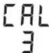
-OhOBpeMeHO HaKHMaTe KHNKy KaNINb6pOBKN 25 N KHONKY HAKNoHa 18 Ha npOTJKeHn OK.2c.
HaHcPiIe OTo6paKaTaCnMBOJ KaIIb6pOKn ooc Z.
-ImMeHHeIIONoKeHHeIaTbHaTakHMo6pa3OM,UTo6blNa- 3epHbIyIpynepeCeKaIBePHTKAbHyIOINHIO HACTeHe.
BoBpEMABTOMaTnueCKOro HbEInIpOBAHHN MIRaET INHmKaTOp IppeDyIpyKDeHHN O HbEInIpOBAHHN 37.
-ПОДЖДITE,пOKAИЗМЕРЛТБНИНСТРУМЕТ He npOи3-BeDET cAMOHIBENHPOBAHNE.

-HaKIMaTe KHOIpKaHNoHa 18nn20
IToTexnopNokaNa3epHbI NyuHe 3aMET MaKcHMaJIbHO npaJIeJIbHOe NOJIOKeHHe N OTOHOWeHIO K BepTKaJIbHOIINHHHaCTHe.
- Ecnn He nonyaetc do6mbctc coBnaedHn nyu a Hnnn, NOBtOpHe npdbIyUe WAr (yCTAHOBKa wTaTnBa, CaMOHmBeHPOBaHne H3MePteNbHO rHcTpMHa, BbpaHBnBaHne NaepHOrO Lyu npn NOMOn KhoNOK HAKNoHa).


-HaKMTHe Ha KHOHky KaHbPOBKn 25, 4TO6bl COxpaHTb KaHbPOBky B naMn.
HaHnCnIe OTo6pa3NTc CmMBoN OKOHaHH KAnHbPobKn.
-BoH36exKaHHe c6oH KaH6pOBKn IO OKOHaHH KaH6pOBKn He06XIOHM O BbIIOHNHTb IpOBepKy TOHOCTH HBeINHOBaHn (CM.《PiObePka ToHOCTH HNBENHOBaHn BBePTKkAIBHom IIOJOKeHHNCTp.354).
Ecn OTKIOHHe BCE epe npeBbIaet npedeNbHO donyCTHMoe 3NaueHene ± 1 MM,OTdaTe N3MePHTeNbHn HCTpyMeHT Ha pOBepky B cepBCHyO MaCTepckyO Bosch.
Yka3aHH no npHMeHeHmO
M3MePHTeBbHb HNCTpyMeNTO6OpyDobAH padHONH-TePfecOM.CoBIOdaTe MeCThbIe ORpaHHueHnno npHMeHeHNO, HAp., B CaMonetax HnN 60nbHuaX.
HcnoIb3yIe BcERda TOnbKO cepeHHy na3epHOH HNN DnO tmetKn. UnpHa Ia3epHOJ NHHN H3MeHReTc No Mepe ydaneHH.
HactpoKa HndKaTopa eHHnCbI N3MepeHHN
PactoHHe MEXdy PNOCKOCTbIO BpaIeHNu CpeHNe IINHne OTOBpaKaaETc HAnCIIeE B [MM] INN [DIOHMax: B DecTnHOM BblpaKeHHN/IpO6bIO].
TQMOCTHEH Ha3aB0e-13ROBHTeBE BAueCTBe CTAHapTHO HAcTPOK N Bb6paHbI [MM].

Haxmte ODHbEmHo KONky HactpoKn ToHOCTN 23 N KONky HAKNoHa 20 Do Tex nop, NOKA HE NOyUte XeNaemyo HAcTPOKy.

PnBbIKIOueHHN HAcTpoKa eINHNUbl N3MepeHNA COXpAH-ETCBA NAMTN.
OuKnIpa6oTbIcna3epHbIM HnCtpyMeHTOM (npHHaJIeXHOCTn)
Ia3epHbte ouKn OTpmbbObHaIO TOKpykaOuHcCBt.5Na- rOdaapr 3ToM yKpaChb cBET na3epa cTahOBHTc6oee np- KMM dnyeNoBeueckoro rna3a.
He npmehnTe na3epHbte ouKn B KaueCTBe 3aunTHbIX ouKOB. Na3epHbte ouKn Cnykat Dna LyuWero paCno3HaBaHnna na3epHoro Lyu, Ondako OHn He 3aunuaot OT na3epHoro nIyueHH.
He npHMeHnTe Na3epHbIe OOKB KaueCTBe conHeHbIX OOKOB HN B yNHCHOM DINHXeHN. Na3epHbIe OOKHe daOT NIOHO 3aunTbI OT yNbTpadHoneTOBOrO n3nyeHHN uyyduaHOT BOCpNRthe Kpacok.


Pycckn|357
Pa60a co wTATHBOM (PnHaIaNExKHOCTN)
H3MepntbHbHnHCTpymENT HMeET rHe3oNoIaTaNB5/8" DnI RopN3OHTaBHorpoexHMa pa6oBt co 7aTaNBOm.YcTaHO Bte H3MepntbHbHnHCTpymENT rHe3dOM NoI aTaNBa Ha pe3b6y 5/8" 7aTaNBa n3aФKKCpnyTe erO c NOMouBIO KpeNekHO BRHTaSTNaBa.
Ha 3C pa3meHoi 1KAnoH aBbDnXHoYacTn Bb MoKeTe HEnocpeCTBeHHO yCTaHOBTcMeIeHne NO BbCote.
Pa6oTa c HacteHHbIM depKxATEm N BbipaBnBaIOUmm y3nom (npHnAdneXhocTH)
BbMoKeTe MOHTnPoBaTb N3MePnteIbHbHbHcHCTpyMeHrTaK
KeHa HAcTeHHOM DepeKaTeIe C BbPaBHNbIoUHM y3IOM
59.3aKpyTneIe Ira 3TOFO BnHT Cpe3b6015/8"62 HAcTeHHoro
depeKaTeIe B rHe3do NOI WtATHB Ha N3MePnteJIbHOM HcHCTpy
MeHTe.
KpeHHe Ha CTHe: KpeHHe Ha CTHe peKOMeHnyETcA, HApP.,IpaB0T BbIe BBICOTb BbIDBHXeHHaHTBa HnI IpaB0Ha HeCTaBnHbOM OCHOBaHHN 6e3 WtATNb.AIg 3TOrO 3aKpeHnTe HAcTeHHbIepKaTeJIb 59 C yCTaHOBneH HBIM H3MePHTbeHbIM IHCTpyMeHTOM, IIO BO3MOXHOCTn, BEPTKALbHO Ha CTHe.
IIMMOHTaKaHaCTHeBbMOKTe3aKpeNtBHaCTeHHbI
IepKaTeIb59cNOMOuBIO KpeNEXHOro BnHTa 60HaIIaHKe
MnPHHOmKc.8MMNINIOBeCtBeroHaDBAKPOUka.
YcTaHOBKa Ha WtATHe: HAcTeHHb IepKxATEb 59 Bbl MoKeTe TaKke 3aKpeNtHa WtATHe, HcNoIb3OBAu DnI 3TOrPe3b6BOe RHe3Do Ha o6OpToHou CTOpHe. TaKoe KpeNneHpeKoMeHdyetca Ooc6eHNO dIn pa6Ot, pNp KOtpbIX NIOCKOCTb BpaUeHnOpHeHTnpoBaHa Ha peNepHyIO NHHIO.
C NOMOUBBbipABHBAIOUero y3naMOXHOpeBNrTaB MOHTPOBAHHN3MepNTbHbNHCPTyMeHnOBePHTKAn (npnMOHTaxeHaCTHe)nnNoTrop3oHTaNN (npnMOHTaxe
HaWtATnBE)BnpeJenaxOK.16cm.DIa3TOroOTnyCTHe BnHT 61 HaBbpaBBHBAIOUeM y3ne,pepeBnHbTeN3MepeNTbHbI HnCTpymEtB HxHHoe NOXKeHHe N CHOBA3aTnHTe BnHT 61.
Pa6oTa c dAnbHomepHoi peKoi (npHaadnexHoCTN) (cm.pnc.H)
I npOBepKn HpeBHOteH npehoCA HAKIOHO peKoMeHnyETc HcNoB3OBA Tb DaNbHOMePHyO peKy 55 cna3epHbIM pHemHHKOM.
B BepxHae qactn daIbHomepHoe peKn 55 HaHeceHa oTHoCHTenbHa H3MePteIbHa 6kana (± 50cm) .Hyb 3a4aetcBAHN3y Ha BbDnKHO qactn. Blaorapr 3OMy MoKHO cpa3y BIDTe bOTKnIOHeHrO 3aDaHHo BbICOTbl.
PpHmepbI Bo3MOxKhIx BnDOb pa6oTbi
PioBepKa rny6HHbI KOtNoBaHOB (cm. pHc. I)
- YctaHOBtE H3MEpHTeHbHb HnCTpyMeHT Ha CTa6HbHyIO NOBepxHOCTb HIN MOHTpyTe erO Ho WtATMBe 63.
-Pa60ta co WtataBOM: HanpabBe TaapeHbI LyuHa HyxHyIO BlicOTy. IpeHeCite/npoBepbTe BlicOTy B TouKe Ha3HaueHn.
Pa60a 6e3 uTaTbA: OnpeIeIte pa3HoCTb B BbICOTe MExy na3epHbIM nyuOM n peepHO ToKo. IpepeHcTe HnnpoeBpTe H3MepeHHyO pa3HOCTb B BbICOTe B HxK-HOM MeCTe.
PnH3mepeHH Ha 6oJIbIHX pacCTOHHX BO 36ExaHne NO-Mex H3mePteIbHbI INHCTpyMeHT peKOMeHdyETcYctHaBaINBAtb Ha UTAInBE B CEHTpe pa6ooye 30Hbl.
-Пи pa60tax Ha HectaBnHbOM rpyHTe yCTaHOBIne n3MePHTeBnHn HNCTpymeHT Ha 7tATNB 63.Bo n36ekaHne OuHbOK n3MepeHn np CoTPaceHnX rpyHTa HnHn H3MePHTeBnHO HNCTpymeHTa CNeIHe 3a TEM, YTObI ChCTema aHTnDpeHa 6blnaakTHBnPOBaHa.
YctpaHHeH HeHcnpabHObTei
HeHcnpaBHOCTN KoOmoOn6Kn

Bcnyae HncnpaBHOCTHa dncnpe oTo6paKaetcKoD Own6Kn.
Ecn HncnpaBHOCTb He ydaIOcb ycTpaHtB, Heo6xoJIMO OTaTb H3MePHTeNbHbI INcTpyMeHT Ha npOBepKy B cepBnchyo MaCtepckyio Bosch.
HnkaTop Ko- Ppo6nema YcTpaHeHne da oun6kn
001OcbYH3mePHTeBHOrO HnCTpyMeHTa HaxoNT-Cs3aIpeEJaMn DnaHa3oHa CaMOHNBeHnPoBaHHa,coCTaBnIOUeOK.8,5% (5^)
-3aHOBOPacnOIOXHTe H3MePHTbHbI HNCTpyMeHTBdONb Ocn X.
002Oc b Y n3meHnTeBnHO HnCTpyMeHTa HaxoDnT- 3a npdeIaMn DnaIa3oHa caMOHBnHpoBaHHa, coCTaBnIOoEoK.8,5% (5°).
-3aHOBOPacnONOXNTEH3MePHTbHbI HNCPTpyMeHTBOnbocnY.
Bosch Power Tools 1609 92A 4DX(28.3.18)


358|Pycckn
| Индikator ko- Пюблесу устраенье Да ош�ки | ||
| 003 (GRL 500 HV) | Оь Z Измергелову История Надостock 下 - 3аноу раслонохину Исторьи впосторьи впосторьи Ся в Веткальnom Р�охени за п徳лам Диапазона салониьроблия, составл Anyo.8,5% (5°). | - 3аноу раслонохину Исторьи впосторьи впostорьи Тыкальnom Р�охени впосторьи впostорьи Зл. Зл. Зл. Зл. Зл. Зл. Зл. Зл. Зл. Зл. Зл. Зл. Зл. Зл. Зл. Зл. Зл. Зл. Зл. Зл. Зл. Зл. Зл. Зл. Зл. Зл. Зл. Зл. Зл. Зл. Зл. Зл. Зл. Зл. Z. |
| 004 Посл История История Надостock 下 - 3аноу усторьи впосторьи Мергелову История Мергелову 下 | В ржиме Надостock 下 - 3аноу усторьи впostорьи Мергелову История Мергелову 下 | - 3аноу усторьи Hstorьну Исторьи Посл Посл Посл Посл Посл Посл Посл Посл Посл Посл Посл Посл Посл Посл Посл Посл Посл Посл Посл Посл Посл Посл Посл Посл Посл Поср Посл Посл Посл Посл Посл Посл Посл Посл Посл Посл Посл Посл Посл Посл Посл Посл Посл Посл Посл Посл Посл Посл Посл Посл Посу Надостock 下 - 3аноу раслонохину Hustopoleny Hustopoleny Hustopoleny Hustopoleny Hustopoleny Hustopoleny Hustopoleny Hustopoleny Hustopoleny Hustopoleny Hustopoleny Hustopoleny Hustopoleny Hustopoleny Hustopoleny Hustopoleny Hustopoleny Hustupoleny Hustupoleny Hustupoleny Hustupoleny Hustupoleny Hustupoleny Hustupoleny Hustupoleny Hustupoleny Hustupoleny Hustupoleny Hustupoleny Hustupoleny Hustupoleny Hustupoleny Hustupoleny Hustupoleny Ha Hustupoleny Hustupoleny Hustupoleny Hustupoleny Hustupoleny Hustupoleny Hustupoleny Hustupoleny Hustupoleny Hustupoleny Hustupoleny Hustupoleny Hustupoleny Hustupoleny Hustupoleny Hustupoleny Hustopoleny Hustopoleny Hustopoleny Hustopoleny Hustopoleny Hustopoleny Hustopoleny Hustopoleny Hustopoleny Hustopoleny Hustopoleny Hustopoleny Hustopoleny Hustopoleny Hustopoleny Hustopoleny Ha Hustopoleny Hustopoleny Hustopoleny Hustopoleny Hustopoleny Hustopoleny Hustopoleny Hustopoleny Hustopoleny Hustopoleny Hustopoleny Hustopoleny Hustopoleny Hustopoleny Hustopoleny Hustopoleny Hustapoleny Hustapoleny Hustapoleny Hustapoleny Hustapoleny Hustapoleny Hustapoleny Hustapoleny Hustapoleny Hustapoleny Hustapoleny Hustapoleny Hustapoleny Hustapoleny Hustapoleny Hustapoleny Hustapoleny Ha Hustopoleny Hustopoleny Hustopoleny Hustopoleny Hustopoleny Hustopoleny Hustopoleny Hustopoleny Hustopoleny Hustopoleny Hustopoleny Hustopoleny Hustopoleny Hustopoleny Hustopoleny HustopoleNY HustopoleNY HustopoleNY HustopoleNY HustopoleNY HustopoleNY HustopoleNY HustopoleNY HustopoleNY HustopoleNY HustopoleNY HustopoleNY HustopoleNY HustopoleNY HustopoleNY HustopoleNY HustopoleNY HustupoleNY HustupoleNY HustupoleNY HustupoleNY HustupoleNY HustupoleNY HustupoleNY HustupoleNY HustupoleNY HustupoleNY HustupoleNY HustupoleNY HustupoleNY HustupoleNY HustupoleNY HustupoleNY HustupoleNY Ha HustupoleNY HustupoleNY HustupoleNY HustupoleNY HustupoleNY HustupoleNY HustupoleNY HustupoleNY HustupoleNY HustupoleNY HustupoleNY HustupoleNY HustupoleNY HustupoleNY HustupoleNY HustupoleNY HustopoleNY HustopoleNY HustopoleNY HustopoleNY HustopoleNY HustopoleNY HustopoleNY HustopoleNY HustopoleNY HustopoleNY HustopoleNY HustopoleNY HustopoleNY HustopoleNY HustopoleNY HustopoleNY Ha HustopoleNY HustopoleNY HustopoleNY HustopoleNY HustopoleNY HustopoleNY HustopoleNY HustopoleNY HustopoleNY HustopoleNY HustopoleNY HustopoleNY HustopoleNY HustopoleNY HustopoleNY HustopoleNY HustapoleNY HustapoleNY HustapoleNY HustapoleNY HustapoleNY HustapoleNY HustapoleNY HustapoleNY HustapoleNY HustapoleNY HustapoleNY HustapoleNY HustapoleNY HustapoleNY HustapoleNY HustapoleNY HustapoleNY Ha HustopoleNY HustopoleNY HustopoleNY HustopoleNY HustopoleNY HustopoleNY HustopoleNY HustopoleNY HustopoleNY HustopoleNY HustopoleNY HustopoleNY HustopoleNY HustopoleNY HustopoleNY Hustopole NY HustopoleNY HustopoleNY HustopoleNY HustopoleNY HustopoleNY HustopoleNY HustopoleNY HustopoleNY HustopoleNY HustopoleNY HustopoleNY HustopoleNY HustopoleNY HustopoleNY HustopoleNY HustopoleNY Hustotopolye Och HustopoleNY HustopoleNY HustopoleNY HustopoleNY HustopoleNY HustopoleNY HustopoleNY HustopoleNY HustopoleNY HustopoleNY HustopoleNY HustopoleNY HustopoleNY HustopoleNY HustopoleNY HustopoleNY Hustobany HustopoleNY HustopoleNY HustopoleNY HustopoleNY HustopoleNY HustopoleNY HustopoleNY HustopoleNY HustopoleNY HustopoleNY HustopoleNY HustopoleNY HustopoleNY HustopoleNY HustopoleNY HustopoleNY Hustoplny HustopoleNY HustopoleNY HustopoleNY HustopoleNY HustopoleNY HustopoleNY HustopoleNY HustopoleNY HustopoleNY HustopoleNY HustopoleNY HustopoleNY HustopoleNY HustopoleNY HustopoleNY HustopoleNY HUSTOPOLY HUSTOPOLY HUSTOPOLY HUSTOPOLY HUSTOPOLY HUSTOPOLY HUSTOPOLY HUSTOPOLY HUSTOPOLY HUSTOPOLY HUSTOPOLY HUSTOPOLY HUSTOPOLY HUSTOPOLY HUSTOPOLY HUSTOPOLY HUSTOPOLY HUSTOPIA HUSTOPIA HUSTOPIA HUSTOPIA HUSTOPIA HUSTOPIA HUSTOPIA HUSTOPIA HUSTOPIA HUSTOPIA HUSTOPIA HUSTOPIA HUSTOPIA HUSTOPIA HUSTOPIA HUSTOPIA HUSTOPIA HUST0PIA HUST0PIA HUST0PIA HUST0PIA HUST0PIA HUST0PIA HUST0PIA HUST0PIA HUST0PIA HUST0PIA HUST0PIA HUST0PIA HUST0PIA HUST0PIA HUST0PIA HUST0PIA HUST0PIA Ha HustopoleNY HustopoleNY HustopoleNY HustopoleNY HustopoleNY HustopoleNY HustopoleNY HustopoleNY HustopoleNY HustopoleNY HustopoleNY HustopoleNY HustopoleNY HustopoleNY HustopoleNY HustopoleNY Ha Ha Ha Ha Ha Ha Ha Ha Ha Ha Ha Ha Ha Ha Ha Ha Ha Ha Ha Ha Ha Ha Ha Ha Ha Ha Ha Ha Ha Ha Ha Ha Ha Ha Ha Ha Ha Ha Ha Ha Ha Ha Ha Ha Ha Ha Ha Ha Ha Ha HA HA HA HA HA HA HA HA HA HA HA HA HA HA HA HA HA HA HA HA HA HA HA HA HA HA HA HA HA HA HA HA HA HA HA HA HA HA HA HA HA HA HA HA HA HA HA HA HA HA NA NA NA NA NA NA NA NA NA NA NA NA NA NA NA NA NA NA NA NA NA NA NA NA NA NA NA NA NA NA NA NA NA NA NA NA NA NA NA NA NA NA NA NA NA NA NA NA NA NA N N N N N N N N N N N N N N N N N N N N N N N N N N N N N N N N N N N N N N N N N N N N N N N N N N M M M M M M M M M M M M M M M M M M M M M M M M M M M M M M M M M M M M M M M M M M M M M M M M M M N N N N N N N N N N N N N N N N N N N N N N N N N N N N N N N N N N N N N N N N N N N N N N N N N NA NA NA NA NA NA NA NA NA NA NA NA NA NA NA NA NA NA NA NA NA NA NA NA NA NA NA NA NA NA NA NA NA NA NA NA NA NA NA NA NA NA NA NA NA NA NA NA NA M M M M M M M M M M M M M M M M M M M M M M M M M M M M M M M M M M M M M M M M M M M M M M M M M F F F F F F F F F F F F F F F F F F F F F F F F F F F F F F F F F F F F F F F F F F F F F F F F F F M M M M M M M M M M M M M M M M M M M M M M M M M M M M M M M M M M M M M M M M M M M M M M M M M m M M M M M M M M M M M M M M M M M M M M M M M M M M M M M M M M M M M M M M M M M M M M M M M M M L L L L L L L L L L L L L L L L L L L L L L L L L L L L L L L L L L L L L L L L L L L L L L L L L L M M M M M M M M M M M M M M M M M M M M M M M M M M M M M M M M M M M M M M M M M M M M M M M M M f f f f f f f f f f f f f f f f f f f f f f f f f f f f f f f f f f f f f f f f f f f f f f f f f f M M M M M M M M M M M M M M M M M M M M M M M M M M M M M M M M M M M M M M M M M M M M M M M M M R R R R R R R R R R R R R R R R R R R R R R R R R R R R R R R R R R R R R R R R R R R R R R R R R R r r r r r r r r r r r r r r r r r r r r r r r r r r r r r r r r r r r r r r r r r r r r r r r r r r l l l l l l l l l l l l l l l l l l l l l l l l l l l l l l l l l l l l l l l l l l l l l l l l l l f f f f f f f f f f f f f f f f f f f f f f f f f f f f f f f f f f f f f f f f f f f f f f f f f g g g g g g g g g g g g g g g g g g g g g g g g g g g g g g g g g g g g g g g g g g g g g g g g g g f f f f f f f f f f f f f f f f f f f f f f f f f f f f f f f f f f f f f f f f f f f f f f f f f l l l l l l l l l l l l l l l l l l l l l l l l l l l l l l l l l l l l l l l l l l l l l l l l l IaespoDy HUSTOCHS OHTOCHS OHTOCHS OHTOCHS OHTOCHS OHTOCHS OHTOCHS OHTOCHS OHTOCHS OHTOCHS OHTOCHS OHTOCHS OHTOCHS OHTOCHS OHTOCHS OHTOCHS OHTOCHS OHTOCHS OHTOCHS OHTOCHS OHTOCHS OCTOCHS OCTOCHS OCTOCHS OCTOCHS OCTOCHS OCTOCHS OCTOCHS OCTOCHS OCTOCHS OCTOCHS OCTOCHS OCTOCHS OCTOCHS OCTOCHS OCTOCHS OCTOCHS OCTOCHS OCTOCHS OCTOCHS OCTOCHS OACTOCHS OCTOCHS OCTOCHS OCTOCHS OCTOCHS OCTOCHS OCTOCHS OCTOCHS OCTOCHS OCTOCHS OCTOCHS OCTOCHS OCTOCHS OCTOCHS OCTOCHS OCTOCHS OCTOCHS OCTOCHS OCTOCHS OCTOCHS OCAOCHS OCAOCHS OCAOCHS OCAOCHS OCAOCHS OCAOCHS OCAOCHS OCAOCHS OCAOCHS OCAOCHS OCAOCHS OCAOCHS OCAOCHS OCAOCHS OCAOCHS OCAOCHS OCAOCHS OCAOCHS OCAOCHS OCAOCHS OCATOCHS OCATOCHS OCATOCHS OCATOCHS OCATOCHS OCATOCHS OCATOCHS OCATOCHS OCATOCHS OCATOCHS OCATOCHS OCATOCHS OCATOCHS OCATOCHS OCATOCHS OCATOCHS OCATOCHS OCATOCHS OCATOCHS OCATOCHS OCAOCHS OCAOCHS OCAOCHS OCAOCHS OCAOCHS OCAOCHS OCAOCHS OCAOCHS OCAOCHS OCAOCHS OCAOCHS OCAOCHS OCAOCHS OCAOCHS OCAOCHS OCAOCHS OCAOCHS OCAOCHS OCAOCHS OCSOCHS OCSOCHS OCSOCHS OCSOCHS OCSOCHS OCSOCHS OCSOCHS OCSOCHS OCSOCHS OCSOCHS OCSOCHS OCSOCHS OCSOCHS OCSOCHS OCSOCHS OCSOCHS OCSOCHS OCSOCHS OCSOCHS OCSOCHS OCAOCHS OCAOCHS OCAOCHS OCAOCHS OCAOCHS OCAOCHS OCAOCHS OCAOCHS OCAOCHS OCAOCHS OCAOCHS OCAOCHS OCAOCHS OCAOCHS OCAOCHS OCAOCHS OCAOCHS OCAOCHS OCAOCHS OCEOCHS OCEOCHS OCEOCHS OCEOCHS OCEOCHS OCEOCHS OCEOCHS OCEOCHS OCEOCHS OCEOCHS OCEOCHS OCEOCHS OCEOCHS OCEOCHS OCEOCHS OCEOCHS OCEOCHS OCEOCHS OCEOCHS OCEOCHS OCAOCHS OCAOCHS OCAOCHS OCAOCHS OCAOCHS OCAOCHS OCAOCHS OCAOCHS OCAOCHS OCAOCHS OCAOCHS OCAOCHS OCAOCHS OCAOCHS OCAOCHS OCAOCHS OCAOCHS OCAOCHS OCAOCHS OcaOCHS OCAOCHS OCAOCHS OCAOCHS OCAOCHS OCAOCHS OCAOCHS OCAOCHS OCAOCHS OCAOCHS OCAOCHS OCAOCHS OCAOCHS OCAOCHS OCAOCHS OCAOCHS OCAOCHS OCAOCHS OCAOCHS OCAOCHS O CAOCHS OCAOCHS OCAOCHS OCAOCHS OCAOCHS OCAOCHS OCAOCHS OCAOCHS OCAOCHS OCAOCHS OCAOCHS OCAOCHS OCAOCHS OCAOCHS OCAOCHS OCAOCHS OCAOCHS OCAOCHS OCAOCHS OCAOCHS OCaOCHS OCAOCHS OCAOCHS OCAOCHS OCAOCHS OCAOCHS OCAOCHS OCAOCHS OCAOCHS OCAOCHS OCAOCHS OCAOCHS OCAOCHS OCAOCHS OCAOCHS OCAOCHS OCAOCHS OCAOCHS OCAOCHS OCAOCHS ODAOCHS ODAOCHS ODAOCHS ODAOCHS ODAOCHS ODAOCHS ODAOCHS ODAOCHS ODAOCHS ODAOCHS ODAOCHS ODAOCHS ODAOCHS ODAOCHS ODAOCHS ODAOCHS ODAOCHS ODAOCHS ODAOCHS ODAOCHS OCAOCHS OCAOCHS OCAOCHS OCAOCHS OCAOCHS OCAOCHS OCAOCHS OCAOCHS OCAOCHS OCAOCHS OCAOCHS OCAOCHS OCAOCHS OCAOCHS OCAOCHS OCAOCHS OCAOCHS OCAOCHS OCAOCHS OSAOCHS OSAOCHS OSAOCHS OSAOCHS OSAOCHS OSAOCHS OSAOCHS OSAOCHS OSAOCHS OSAOCHS OSAOCHS OSAOCHS OSAOCHS OSAOCHS OSAOCHS OSAOCHS OSAOCHS OSAOCHS OSAOCHS OSAOCHS OCAOCHS OCAOCHS OCAOCHS OCAOCHS OCAOCHS OCAOCHS OCAOCHS OCAOCHS OCAOCHS OCAOCHS OCAOCHS OCAOCHS OCAOCHS OCAOCHS OCAOCHS OCAOCHS OCAOCHS OCAOCHS OCAOCHS OCAAOCCHPOM MFAOCHS OCAOCHS OCAOCHS OCAOCHS OCAOCHS OCAOCHS OCAOCHS OCAOCHS OCAOCHS OCAOCHS OCAOCHS OCAOCHS OCAOCHS OCAOCHS OCAOCHS OCAOCHS OCAOCHS OCAOCHS OCAOCHS OCAOCHS OLAOCCHPOM MFAOCHS NAOCHS NAOCHS NAOCHS NAOCHS NAOCHS NAOCHS NAOCHS NAOCHS NAOCHS NAOCHS NAOCHS NAOCHS NAOCHS NAOCHS NAOCHS NAOCHS NAOCHS NAOCHS NAOCHS NAOCHS NAOCHS NAOCHS NAOCHS NAOCHS NAOCHS NaoCHS NAOCHS NAOCHS NAOCHS NAOCHS NAOCHS NAOCHS NAOCHS NAOCHS NAOCHS NAOCHS NAOCHS NAOCHS NAOCHS NAOCHS NAOCHS NAOCHS NAOCHS NAOCHS NAOCHS NAOCHS NAOCHS NAOCHS NAOCHS NAOCHS NNOCHS NNOCHS NNOCHS NNOCHS NNOCHS NNOCHS NNOCHS NNOCHS NNOCHS NNOCHS NNOCHS NNOCHS NNOCHS NNOCHS NNOCHS NNOCHS NNOCHS NNOCHS NNOCHS NNOCHS NNOCHS NNOCHS NNOCHS NNOCHS NNOCHS N NOCHS NNOCHS NNOCHS NNOCHS NNOCHS NNOCHS NNOCHS NNOCHS NNOCHS NNOCHS NNOCHS NNOCHS NNOCHS NNOCHS NNOCHS NNOCHS NNOCHS NNOCHS NNOCHS NNOCHS NNOCHS NNOCHS NNOCHS NNOCHS NNOCHS NNoCHS NNOCHS NNOCHS NNOCHS NNOCHS NNOCHS NNOCHS NNOCHS NNOCHS NNOCHS NNOCHS NNOCHS NNOCHS NNOCHS NNOCHS NNOCHS NNOCHS NNOCHS NNOCHS NNOCHS NNOCHS NNOCHS NNOCHS NNOCHS NNOCHS N NoCHPOM MFAOCHS NAOCHS NAOCHS NAOCHS NAOCHS NAOCHS NAOCHS NAOCHS NAOCHS NAOCHS NAOCHS NAOCHS NAOCHS NAOCHS NAOCHS NAOCHS NAOCHS NAOCHS NAOCHS NAOCHS NAOCHS NAOCHS NAOCHS NAOCHs OCAOCHS OCAOCHS OCAOCHS OCAOCHS OCAOCHS OCAOCHS OCAOCHS OCAOCHS OCAOCHS OCAOCHS OCAOCHS OCAOCHS OCAOCHS OCAOCHS OCAOCHS OCAOCHS OCAOCHS OCAOCHS OCAOCHS OCAOCHs OCAOCHS OCAOCHS OCAOCHS OCAOCHS OCAOCHS OCAOCHS OCAOCHS OCAOCHS OCAOCHS OCAOCHS OCAOCHS OCAOCHS OCAOCHS OCAOCHS OCAOCHS OCAOCHS OCAOCHS OCAOCHS OCAOCHS OCAOA CHTOKON MFAOCHS NAOCHS NAOCHS NAOCHS NAOCHS NAOCHS NAOCHS NAOCHS NAOCHS NAOCHS NAOCHS NAOCHS NAOCHS NAOCHS NAOCHS NAOCHS NAOCHS NAOCHS NAOCHS NAOCHS NAOCHS NAOCHS NAOCHS NAOCHS NAO CHTOKON MFAOCHS NAOCHS NAOCHS NAOCHS NAOCHS NAOCHS NAOCHS NAOCHS NAOCHS NAOCHS NAOCHS NAOCHS NAOCHS NAOCHS NAOCHS NAOCHS NAOCHS NAOCHS NAOCHS NAOCHS NAOCHS NAOCHS NAOCHS NAO CHTOKON MFAOChB NAO CHTOKON MFAOChB NAO CHTOKON MFAOChB NAO CHTOKON MFAOChB NAO CHTOKON MFAOChB NAO CHTOKON MFAOChB NAO CHTOKON MFAOChB NAO CHTOKON MFAOChB NAO CHTOKON MFAOChB NAO CHTOKON MFAOChBNAO CHTOKON MFAOChB NAO CHTOKON MFAOChB NAO CHTOKON MFAOChB NAO CHTOKON MFAOChB NAO CHTOKON MFAOChB NAO CHTOKON MFAOChB NAO CHTOKON MFAOChB NAO CHTOKON MFAOChB NAO CHTOKON MFAOChB NAA CHTOKON MFAOChB NAA CHTOKON MFAOChB NAA CHTOKON MFAOChB NAA CHTOKON MFAOChB NAA CHTOKON MFAOChB NAA CHTOKON MFAOChB NAA CHTOKON MFAOChB NAA CHTOKON MFAOChB NAA CHTOKON MFAOChB NAA ChTOKON MFAOChB NAA CHTOKON MFAOChB NAA CHTOKON MFAOChB NAA CHTOKON MFAOChB NAA CHTOKON MFAOChB NAA CHTOKON MFAOChB NAA CHTOKON MFAOChB NAA CHTOKON MFAOChB NAA CHTOKON MFAOChB NAA CH TOKON MFAOChB NAA CHTOKON MFAOChB NAA CHTOKON MFAOChB NAA CHTOKON MFAOChB NAA CHTOKON MFAOChB NAA CHTOKON MFAOChB NAA CHTOKON MFAOChB NAA CHTOKON MFAOChB NAA CHTOKON MFAOChB NAA CHT200000000000000000000000000000000000000000000000000000000000000000000000000000000000000000000000000001000000000000000000000000000000000000000000000000000000000000000000000000000000000000000000000000000 |

Pycckn|359
HecnpabHocn6e3KoDa oH6Kn
CepBnH KOHCyNbTHpOBaHHe Ha npeDMeT HcNoIb3OBAHn npOdyKuHH
CepBnchA MaTepecka OTBeHr Ha BCE Baun BOpocb no pemOHTu 6cbIyKbAHnIO BaWero npOdykTa H No 3aIpaCTaM. MoTaxhHbIe UepTeKn HnHfOpMaUIO No 3aIuaCTaM BbHaJndete TaKke no aDpccy:
www.bosch-pt.com
KoNneKTbB COTpyDnHKnOB Bosch, npedocTabnHOuH KONcylbTaun Ha npedMeT nCOnb3ObaHn npOdykuH, cydoBbCTBHeM OTBeHT Ha BCE BaHn BOpocb oTHocHTeNbHoro Hauwe npOdykuHH ee npHaNDnEHXoTe.
Tpojanynta,BO Bcex 3anpocax 3akazax 3anacte 6o3aTeIbHo yka3bIaIte 10-3HaHbI TOBapHbI HOpE nO 3aBoDcKoTabnueKeNdennr.
BaWytINHcKoe WOCCE, Bn.24
141400,r.XHMMK,MockOBCKa8o6n.
Te.:+78001008007
E-Mail: info.powertools@ru.bosch.com www.bosch-pt.ru
Bosch Power Tools 1609 92A 4DX(28.3.18)


360|Pycckn
Benapycb
IN《P06epTbOu》OOO
CepBnchbI ueTp no 6cnyxHBaHHIO 3NeKtpOHHCTpyMeHa. yI.TmHpR3eBa,65A-020
220035,Γ.MHHCK
Ten.: +375 (17) 254 78 71
Ten.: +375 (17) 254 79 16
a c: + 375(17)2547875
E-Mail: pt-service.by@bosch.com
ApmeHHA3ep6aJxHAn,py3nKnprH3ctan,MoHro- HnTaqxHKCTaH,TypkMeHHCTaH,Y36ekHCTaH
TOO «PoBept Bou» (Robert Bosch)
Power Tools nocennpo#aJHoe obcnykBaHne npocnK TpaBm6ka 169/1
050050 AImaTbI, Ka3axCTaH
Cnyke6haa 3n. nouta: service.pt.ka@bosch.com
OΦηnαλnbHbBBe6-caɪT: www.bosch.com,
www.bosch-pt.com
TpaHcnpToPbOvKa
HaBNOKeHHbIJIINTHeBO-HOHHbIe AKKMyJITOpHbIe 6aTapei paCnpoCTpaHHTOc Tpe6oBaHHB OTOHOeHHN TpAHCnOpTNPOBKN ONaChbIX Tpy3OB. AKKMyJITOpHbIe 6aTapei MOrTy peBo3NbCAmHM NOLb3OBaTeMe ABTOMo6uNbHbIM TpaHcNOptOM 6e3 Heo6xOIMoCTn COJIIODeHHaDIOJIHHTeNBbHbIX HOpM.
PnnepeBoske C npBneueHem TpebXnLIu (Hanp.: camoneTOM HIN TpaHCnpTHbIM 3KcneDHTOpOM) Heo6xOdMIO CO6NIOaTb OOCbIe Tpe6oBaHn KynakOBKe I MapKnpoBKe. B3tOMCnyae PnPi NDroTOBKe rpy3a K OTnPaBKe Heo6xOdMIO yuaTne 3KcneptA NO anChbIM rpy3am.
OTnpabnIte aKymyIaTOHy 6aTapeIO TOnbKO c HEnOBpeKJdeHHbIM KOpNcOM.3aKneIe OTKpbITbIE KOHTaKTbI yNaKyIte aKymyIaTOHy 6aTapeIO Ta, YTObI OHa He NepemUaIac BHYTpH yNaKOBKn.
IoxanyiSta,co6nOdaTae TaKxe BO3MOxHbIe DOONHHTenB HbIe HaOnOHbHbIe npednncAHJ.
YTHIN3aun

CtpontelbHn na3ep,3apndHoe yctpoCTBO,na3epHn nphemHK, aKKyMnTOpHbte 6batape, pinnadIeXHOCTN uynakOBky cneety TYNHNpOBAb 6e0NaChbIM nOkpyxaooien cpebl6pa3om.

He b6pa6bBaTe cTpoNTeBhl na3ep, 3apnHoe yctpoCTBO, na3epHbI npHemHNk n AKKyMyIaTOpHbI 6batapeu/baateeKu B 6bITOBO MycOp!
AkkymyIaTOpbl,6aTapeH:

Li-Ion:
IoxaIyIcTa,yuTbIaIeYka3aHneBa pa3JeE «TpaHcIopTpIPOBka», ctp. 360.
Bo3MOXHbH3MeHeHHa.


YkpaHcbka|361
yKpaIHcbka
3mict
Bka3iBKn 3 TeXnKi 6e3neKn 362
Bydibenbni naep 362
3apnpiipniDdoakymyTropho6atapei 363
Ia3epHn npHMaU/nybT dNCTaHcI Horo ynpabInHH . 363
Onnc npoodykry i nocnyr 364
Pn3naueHH 364
Bydibibbni na3ep GRL 500 H 364
Bydibibbni naep GRL 500 HV 364
IasepHnn npnMaU LR 50 364
3o6paXeHI KOMnOHeHTN 364
TexhiuHaH 365
MoHTax 366
3apKaHnAkyMnyTOpHnx6TaapeB BMIpOBaIbHoI hCTpyMeHTy Ia3epHOrO npHmMaA (INB.MaI.A-B) .. 366
IINKATOP3aPdKeHocTe6aTapeNoK 366
3apxknaa kymyntropho6atapei 367
Bka3iBkn 10do onTImaIbHoro noBODKeHHa3 akyMnTOpom 367
Ecknnyatauaia 367
Pouatokpo60n 367
BCTaHOBnEHBNMIPOBaIbHOr npHaNy 367
YnpaBnHHBmIPIOBaIbHIM IHCTpyMeHTOM (INB.Man.C) 367
Poboyi stann 368
BMnKaHHBmKahH 368
Pouatokpo60n 368
BMnKaHHa 368
BIMKahra 368
Pekim ouikyBaHHa 368
ABTomatnue BmHKaHH 369
Baapeika peanbhoro yacy RTC (Real Time Clock) .. 369
CunHaniaiJnIaXHcTyBjKpaIckn 369
YbIMKHeHHcHnHJIaIaIgIyIa3xHcTByBJ KpaJixKn.369
PnKlaI BHKOpHcTAHN CnHJIaIiIaIiIIN3axHcty BID KpaIjKKn 369
IINKAtOpNnepeBipKnKalibpyBaHHn (nonepedkeHH
npo npuyenHH KaniibpyBaHH) 370
PnpxOByBaHHI INdkaTOpIB NnonepJxKeHHNpno npoyuHnKaIbpyBaHH 370
Pekomehdobahn nopraok di nicna nobidomneHH npo nepebipky kani6pybaHH 370
Pekmm po60n 371
IinioeXiY 371
PotauiHHn peXMM 371
OrnIe peKHMIB po60Tu 371
ABTomatnue HibenIOBaHH. 371
ABTomatnue HibenlObaHHn nicnyyBMkHeHHn .371
ABTomatnueH hibenlboHH naaceknyataa..371
PekHM HBeJIIOBaHHy3IOBxOJHOi oci 371
HanaityBaHHaKaHaXnny 371
peKHM cepeHboi nHH (nB.MaI.D) 371
PnBnHnEHH nouyky cepedhboi niiHaepHoro npMaay 372
cnTeMa aHTnpei fy (ADS) 372
BmHKaHHnCnCTeMM aHTnDpeHpy 372
JIHHHmpeKHMyBepTKKaNbHOMypeKMI (GRL500HV) 372
PexnM ceHTpaIbHOI liHII npH nIHINOMy peXnMI (nB.MaI.E) 372
PnBnDneHn nouyky cepehboi niHlaepHoro npMaay .373
IINKATOP BIDHOCHOI BCOTN (INB.MaI.F) 373
Pobota 3 naeepnHm npHmaem. 373
Papio36a30MKixBmipHOBaHbHM IHcTpymeHTOM iIyIbTom IINCTaHciHOrO ynpabnHHra/na3epHM npmaem 373
HanaTyBaHH3BkyOBOro CnHany/ryHocti 373
Bn6ip hanaWtbyBaHH iHnKaTopa cepeHb0i nihii...374
IIndkaTopn HappMky 374
3axncha fynkui Strobe ShieldTM 374
P03haeHH 374
PiicbiuyBaHHaHnne 374
3aKpInnEHHaDOnOMoIO TpImaua daNEKOMipHoI peKN (INB. Man. G) 374
IpeBipkatoHocti BmipHOBaHbHoro npnady 375
FaKToP,IO BnNBAIoTB HaTOHcTb.375
Ipebeipka Touhocti HIBeIOBaHHy rOpHOrTaBHOmy nOxKeHHI 375
IpeBipKa ToUHcTi HiBeJIIOBaHH y BepTKaIbHOMy noJoxeHH (GRL 500 HV) .375


362 | YkpaɪhcbKa
KanibpyBaHHB HMIipIOBaIbHOro IHCTpyMeHTa 376
Kani6pyBaHHBiciX 376
Kani6pyBaHHBiciY 376
Kani6pyBaHH Bici Z (GRL 500 HV) 377
BkaizIKn 1o0 p60tn 377
HanaTbAHnIHINKaUOHNuB BmipOBaHH. 377
Po60n3daKeKOMipHO peKoIO (npnaIaIaIaIaIaIaIaIaIaIaIaIaIaIaIaIaIaIaIaIaIaIaIaIaIaIaIaIaIaIaIaIaIaIaIaIaIaIaIaIaIaIaIaIaIaIaIaIaIaIaIaa
PnKnaPi npoToN 378
IpeBipka rHbHH KOTNoBaHIB (INB. Man. I) 378
UcyHHe HecnpaBHOCTe 379
Henonakki koki n ommok 379
HepoJauKb63 KoIy nOmIIKn 380
Texnue 6cbnyrobyBaHHicepicBic 381
TexhiueoocnyroByBaHHIOuHHeHH 381
Cepic Ta HadaHn KaHcybTaui 0do BHKOpctAHn npodyu.. 381
YkpaHa 381
TpaHcnpotyBaHH 381
Ytuniana 381
Bka3iBkn 3 texhikn 6e3neKn
BydibenbHn na3ep

IpoountaTe BcI Bka3iBkn iDotpmytece
IX,IO6 IpaOBAth 3 BmIPIOBaIbHM
InCTpymEtOM 6e3neuHO Ta HadiHoo.
BHKOpHCTAHN BmIPIOBaIbHoro
InCTpymEtA 6e3 D0tPMaHHn
HCTpykui MoKe np3BecTH Do NOuKOJKeHHI ITERpOBOAHx 3axCHnx MexaH3mIB.HiKoH He DOOBtenepeXyBaHbNl TaBnKn HA BmIPoBaNbHOmy HcTpyMeHTIO HeBnI3HaHNoCTI. IO6PE 3EPIAITE UI BKA3IBKN I NEPeDABAAITE IX PA3OM 3BMIPOBALbHM IHCTPYMEHTOM.
06epexho-BNKOpCTaHHa3ac06IBocnyroByBaHHa HAcTPOBAHHa,IOBip3HbOTcB BID 3a3HaueHnX BuiInctpyku, a6oBHKOpCTAHnDO3BOeHnX 3ac06iB y Heo3BOeHm CnOci6, Moke np3BoDHTn Do He63neueHx BN6yixB BnnpomihOBaHHa.
BmipobalbHH IHCTpMeH NOCTaAcTbc3 3 nonepeJxbyBaIbHO TO TabNtKoHO (Ha 306paXeHHI BmipobalbHorO IHCTpMEny HA CTOpINi3 MAnIOHKOM BOHA Ns3HaueHa HOMepOM 8).
Laser Radiation Class 2 do not stare into beam IEC 60825-1:2014 <1mW,635 nm
A KIIO TEKCT nonepdkyBaIbHOI TaBnHcN He Ha MOI BaOoi KpaiHH,3aKnTe Horo nepe npoE eknnyaTaicio dOdaHOI hakneKOHO HA Moi BaOoi KpaiHH.
He HapabnIte na3epHn npomInb Ha IIOpe a60 TBapHn, I cami He DnBtbc Ha npmN a6o BiO6paXyBaHn na3epHn npominb. Bih MoKe zacniNTn iHux IIOde, cnpuHHnTn Heaachi BnAaKn a6o NooKoNDTH Oui.
ypa3i noTpannaHHn na3epHoro npomeHa BOKO, HABMNcHe 3aNNIOuITb oui i BiDpa3y BiDBepHITbcB iD npomeHa.
HiYoro He MInHrTe BnAzePbHomy npncTpoi.
He BHKOPHCTOByte OkynpH dnn po60n 3 na3epom B kocti 3axncnXOkynpIb. OkynpH dnn po60n 3 na3epom npn3haeHi nla KpaUoro po3ni3HaBaHHna3epHoro npomeHa, aJe BOH He 3axnauoB iD na3epHoro npomHH.
He BHKOPHCTOBYte OKyIaPn DnIpo6Otn 3 naePOM nIaXhCTy BiD coHua I 3a KePmOM. OkyIaPn DnI po6Otn 3 naePOM He 3axuiaoTb NobHcTIOB yΦ- npomHH i noripuytbp0ni3HaBaHH KOnbopiB.
Bidabaante CBiB BmipobanbHn npnaHa peMOHT NHE KeaniKIOBAM Haxixaum Ta NHe 3 BHOPcTahHM opriHanbHNx 3aunactHH. TInkN 3a TaNX yMOB BaW BmipobanbHn npnaI hadani 6ye 3aNNuATHC 6e3neuHIM.
He Do3B0nIte DITM KOpHCTyBaTHc6e3 Harnny na3epHM BmipIOBAbbHM npHnaOM.BoHH MoKyTb HeHaBMNChe 3acIniHTn IHxNIOJe.
He npaiothe 3 BnMipOBaIbHm npnaIom y cepeoBni, de ichyeche6e3neKa Bb6yXbHaCIOK npcyTHOCTI ropouxpiin, ra3iB a60 nHy. Y BnMIPOBaIbHOMy pNIIaDi MOkytB yTBOpOBaTHcI cKpn, BID AKNX MOKe 3aAMATNCnA n6 npn.

3axnauTe BmipIOBbHn npnaD BiTenna, 3OKpema,HanP.,BiD coHryHnx IpomehIB,BORHO BOH TaBOrH. IChyE He6e3neKa B6xy.
PnHnPaBnBnMy BnKOpNCTaHHi 3 AkymyTApTOH6 GatapeIMOKe NOeKTNI pINHa.YHNaIe KOHTAKY 3 HeIO.PnBnAaKObOMy KOHTAKTI pOMHHe BINoBIDHe MlCe BOIO. AkuO pINHa NtpanHb Ooi, DoaTKoBO 3BepHITcBdo NIKAPA.AkymyTOpHa pINHa MoKe cnpuHNrTH NoDpa3HeHHu KIPn a60 onIKn.

YkpaHcbka 363
Pn nookxehni 60 HenpaBnblh Eeknnyatau acymyantopho6atapeimoxe BHXoHTn nap. Bnyctitcbixne nobitrpi - y pazi ckapr-3bepHtbcn do nikapn. Nap moxe npdaaHOBaTn dxaJIbHI wJnx.
3apnAteakymnTophy6atapeo nneBdoaHomy 3apnHomy npncptoi.3apnHn npncptpi,npnHaehnnIgKnKpeTHnx akymnTOpHHx 6atapei,MOKe 3aMaTHCN,AKUOBMy 6ydybTB 3apnJXaTHNHepeD6auehi akymnTOpHi 6batapei.

HeBCTAHOBIOIte BmipIOBaIbHn npnaI aB3INPHN ⅢpOBNyBd
KapIOCTHMnIaTOPiB.MaHTIN BmIPHO BaIbHOro pPnHa Ta B3INpHOrO Ⅲta CTBOPOITb None, AKe MOKe HErATBH0 BnINBaTH Ha cyHKUIOHaJIbHy 3daTHiCtB KApIOCTMnIyTOpA.
TpmaTe BmipIOBbHn npnaI aB3npHn nHT ha BiDcTaI BiMaHrTHnx HocIIb DaHnx IuyTNbNx Do MarHITnx nonIB npnaIaB. MaHITn BmIPHOBbHO rnpaNy Ta B3npHoro ta CBOcIO diIO MOkyb np3bOHTn do Heo6opOToi BtpaT daHnx.
3apdHn npctpi do akymyraTropho6atapei

PpounaTe Bc3acTepeXeHHbKb3iBKn. HeOpTnMaHn3acTepeXeHbIKBa3iBOK MoKe np3BeCTn Do ypaXeHH eNEkTPnuHM CTpyMOM, noXeJ ta/a6o cepno3HNx TpaBM.
Le3apHn npctpi He nepe6aueHn Iy BHKOpHCTaHHa DItbMn i oc6amn 3 06mexeHMM i3uHMM, ceHCOPHM Ta po3ymOBHM 3i6HOCTaMn, a6o HeodcTaTHIM DOCBiOM Ta 3HaHHMaN. DITAM BIKOM Bi8 pokIB Ta oc6am 3 06mexeHMM i3uHMM, ceHCOPHM Ta po3ymOBHM MOxJIHBOCTaMn a6o HeOCTaTHIM DOCBiOM Ta 3HaHHMaN Do3-BOJcTBcA KOpHCTyBaTHCzHM 3apHnHn npHcTPOeM Ihwe NiHaIaDom a6o Ako BOHn OTPMaH N BiINOBIDHi Bka3IBKn 0do 6e3neuHOro BVKOpHCTaHHaCboro 3apHnO npHcTPOU i PO3yMIOTb, Aky He6e3Neky Bin Hece. BInwomy BNpaKy MoXJIbE HnpaBnIbHe BVKOpHCTaHHa Ta He6e3Neka OdepJahnn TpaBM.
IOrnaTe 3a DiTbMn iD qac KopnctyBaHH, ouHneHH iTexHiHoro 06cnyroByaHH. IITn He noBHHI rpatn i3 3apAHN mPnCTpoem.

3axnauTe 3apdHnn npncptiBid douyi Bonr. NotpanHHBAoBn B 3apdHnn npctpi 36inbwye pniHK ypaXeHHN eEKeTpnuHm CTpyMOM
3apnKaTe BmipOBaBbHn IHcTpMeHTnHe 3a donomoroIOdoaHO3apdHO npctpoio.
TpmaTe 3apAHHn pncptiB uHcToT.3abpydHeHHMOxyt np3BOHTNo ypaKeHH eEkeTPuHHm CTpyMOM.
KoKHH pa3 nepeB BHKOpHCTAHMM nepeBipnTe 3apnctpi, Ka6bI I wTencen. He KOPHYTEcA 3apnHMM npHCTPOeM, AaQo NOMITNE 0nKoJXeHH. He po3KpBaIte 3apnHMM npHCTPII camOCTIH; pemHTyBaTH HOro Do3BOANETCBNHe KBAiDfIKOBAHM qaxIBzM 3 BHKOpHCTAHHM opnHbHNx 3aunactH. NowKOJXeHH 3apnHMM npHCTPI, WHP a6oWtencB 36InbUye pINHk ypaXeHH eNEKTPuHMM CTpyMOM.
He Kopnctyteca 3apdHMM npcTpoem Ha ochobi, moMe neKo 3aMthcna (Hanp.,Ha panepi, TektbnhX MATEpianax Too) a6o B roPouomy cepedobu. HarpiBaHHra 3apdHoro npcTPOIO nIac 3apdKaHH MoKe np3BOOHTN DO NOKExi.
PnnookdHexhi a6o HnpabHbHomy BHKOpctaHHi akymyIaTPOHO6batapeIMoKe BHXOHTn nap. BnycITb cbiXe noBIPr i-y pa3i ckapr-3BepHtbcn do nikapra. Nap moKe BHKInKaTH NOpa3HeHH DxHaJIbHnx IJRAXIB.
Ja3epHn npHMaU/nybT nctaHoiHoro ynpabniHH

Ipoounte IBKohnyte yci Bk3iBKN. IO5PE 36EPIGAITE BKA3IBKN.
BidabaTc BmBnMipOBaHbNn npHaHa peMoHT Nnue KbaNlifKOBaHm FaxiBaum Ta nIe3 BHKOpCTAHm OPrHnHaBbHN 3aNaCTNH. TInkN 3a TaKnx yMOB BaWnBmIPoBaHbNn npHaad i Haanii 6yde 3AnuATnc 6eNeuHM.
He npaoute 3 BmipobalbHn npnaoom y cepeobu, de ichyeche6neka Bb6xy Bhaeniok npcytocti ropuhix pihn, ra3ib a60 nnny. Y BmipobalbHOMy npnadi MOKyb tyBOPOBaTHc icKpn, BiJHKX MoKe 3aHaMaTHc nn a60 napn.

3axuaiTe BmipoiBnblnn npnaD BiTenna, 30Kpema,Hanp.,BiD coHryHnx IpomehIB,BORHO, BOIN TaBOON. IChye He6e3neKa B6xy.
PnHnPaBnBHOmy BnKOpNCTaHHI 3akymyTAPHO 6atape moke noteKTPiHa. YHnKaTe KOHTAKTy 3 Heo.Pn BNnAdKObOMy KOHTAKTI pomHne BiNoBiDHe MlCe BOIO. AkuO piHa NotpanHna B Ooi, DoaTKOB 3BepHtbcdo NikapA. AkymyTOpHa piHa MoKe cnpuHNrTH NoDpa3eHHH Wkipn a60 onIKn.


364 | YkpaɪhcbKa
Pn nookxehni 60 HenpaBnblh Eeknnyatau acymyantopho6atapeimoxe BHXoHTn nap. Bnyctitcbixne nobitrpi - y pazi ckapr-3bepHtbcn do nikapn. Nap moxe npdaaHOBaTn dxaJIbHI wJnx.
3apJxHaeAkyMnTOpHy 6atapeo Nnue BdoaHomy 3apJHOMy npctpoi.3apJHn npctpi, npn3aueHn dIa KOHKpTeHHx akymyTAOPHX 6atapei, MOKe 3aMaTHcN, AkiO B HbOmy 6ydyTB 3apJxHaTHcHenepeB6aueHi akymyTAOPHi 6batapei.
Pnpnad npn3haeHnn DnBn3haeHH Ta nepeBipKn TouHo Tropn30HTaJIbHNX LIiHi BnCOTn, BepTNKaNbHNX NiHi, NiHi 36Iry Ta TOOK BNCKA.
BmipobalbHHHINCTPymENTn3HaehnIaBHKOpCTaHHHaDbOPI,ane Horo MOxHa BHKOpCTOByBaTHTAKoKIBpMIMiEHHX.
Ja3epHn npHMaU LR 50
Ja3epHnI npHmau npH3aueHH nIa WbNdkoro 3HaXoJKeHH Ja3epHnx IpomehIB, 0o o6epTaIObCBA, Ta IINCTaHuiHORO ynpabHH 6yIDBeBHM JAsepOM.
JaapeHn npmMaup npdAaTHn DnBHKOpncTaHH BcepeHnipMiuChb Ta 3OBHI.
BkaibKa: LR 50 cnykntb k B kocti na3epHoro npnmaay, Taik B kocti nybta dctanuHoro ynpaBnHH. Dn6nbwoi 3pyuHoctiy noanbwoMy LR 50 6yhe HaNBatcra «na3epHm npnmaayem
3o6paXeHi KOMnoHeHTn
Hymepaui 36paekhenx KOMnoHeHTB NocnlaTbcra Ha 36paekhen 6ydiBEnbHO rnaepa, 3apdHoro npctpoTu naepHoro npmMauHa CTOpIHkax 3 ManIOHKAMn.
Bydibenbni nacep
1ПлЯМВСнИ ПпOMIHb(GRL500HV)
2 Buxid naeepHoro npomeHa
3KpnuKa npn3Mn (aHOMiH,CKNO)
4 Cbitnoio cnHnaiiaqii dna3axncTy bD kpaiaKKn
53apndi KOHTAKTNnnaaepHOro npinMaua
6 C7aui3apKni 36epirannnna naaepehoro npimaua
7 Na3epHn npomihb
8IOnepedjyBaIbHaTa6nUkaDnpo60TH3na3epoM
9 CepiHn Homep 6yDIBenbHoro na3epa
10 Hh3o nIa 5/8" (BepTkaJIbHe) (GRL 500 HV)
11KpnwkaTHi3daDn3aapdKaHH
12HiaDnIaTbBa5/8"(ropn30HaJIbHe)
13 KhoNka CkDaHnHa
14HnDIO DnI 3aPAnKaHHN
Ia3epnH npHmau
15 Dusnnnei
16No3haqka cepeHH
17BmHKaY
18 Khonka Haxiny Btropy
19 KhoNka peXmMy cepedhboi niiH
20 KhoNka Haxiny BHH3
21 Khonka pejkmy ouikyBaHHH
22 KhoNka CnHnHaI3auii DnA 3axncTy bD KpaJixkN
23 KhoNka HAcptpoBAHHH TOUHOCTI BMMIPHOBAHH
24 KhoNka 3BykoBOrO cRHaNy/ryHooCTi
25 Khonka kani6pyBaHHa
26 PnHmAlbHe BIKOHue dIaIaIaePHOrO npomeHa
27 CepiHnH Homep na3epHoro npHMaHa
28 3apdhi KOHTN
IIndKaToPn Na3epHOro npHMaua
29 INIINKATOP 3APy akymynTOpHOi 6aTapei 6yDIBeHOro na3epa
30 INIKAToP 3apAkyakymyIaTOpHOI 6aTapeI NaepHOrO npnMa4a
31 TeKcTOBm iHnKaTOp Haxny/NoMnKn
32 TeKCTOBH iHnKaTOp BIDHOCHOI BNCOTI/HTepBany Kani6pyBaHH
33 INdikatop padio38'3ky
34 INIKATop BHXOy 3a Meki D03BOJeHOro TEMpePaTyphoro Diana30Hy
35 IIndkaTop iHTepBany kani6pyBaHHa
36 IIndikatop cnHaniaauiI dIa3xNCTy BiD KpaiajKk
37 INdkatop nonepdxkenn np HbeIOBaHH
38 INdkaTop nonepeJxKHeHHn pro cTpyCN
39 INHKAtop HANPMy «IaepHn IpnOMIHb HAD CEpeHbOIOJIHICIO
40 INIkaTOp HnnpMy «Ia3epHn npomHb niD cepedhboo nhiicio
41IndikatoppekmyHaxiny
42 Pexim cepenboi nii
43 IndkaTop cepenboi niHii
44IndikaToppekmyOikyBaHH
45 IIndkaTop 3BykoBOrO CnTHaIy/ryHocti
46 INIKATOP TOHOCBI BMIMIOBAHHA《TOHHe HanaHTyBaHHA
47 INIKATOP TOHOCI BMMIPIOBAHHRA(cepeHHe HanaHTyBaHHA
48 INIKATop TOUHOCTI BIMIPIOBAHHA「rpy6e HanaHTyBaHHA
3apdHH npHcTpi
493apdHn npnctpi
50 3apdHm wTekep
51 3'eHnBaHbHm ITeKeP
52 Wtencenb


YkpaHcbka 365
Pnna/3anactnn
53 Tpmaa danekomiphoi peken
54ΦicCyBaIbHnTbHHTTpMaHa daJeKoMipHo peKN
5Danekomiphapeika
56 KpinHbHn TbHnT TpMaHa daIaneKoMipHO peiKu
57 Batepnap TPhMaa daNeKOMipHo peKN
58BncyBa pama naasepHoro npnMa4a
59 HactiHHe KpinneHn/npinctpiJn Dn BpibBBOHnA
60 KpinHbHn TBHNT HactiHHoro KpInHeHa
61 TbHnHa nPnctpoi DnBnPiBnIOBaHHa
62 [BnHT 5/8"Ha HactiHHOMy KpInneHHi
63UtaTHB
64 Okynprn dIra po60Tu 3 na3epom
65Футлар
306paxehe a6o onncahe npnaed He BxoHb TcTahaptnn 06cgr noctabKn. NobHH acoptmert npnaed Bn 3haJeTe B haui nporpami npnaed.
Texhi dani
IINBIO6paqhenr cTany 3apny AkyMnyTopho6atapei BmIPOBaHbHOI INCTpyMeHTa I na3epHO npnMaHa neo6xIDNo,IO6 BmIPOBaHbHIn INCTpyMeHT 6yB yBMKHeHH (INB.«BMKaHnRA,CTOP.368).
| Показааннaya Ди检плия | Зразецни СмнICTь | Занихочасу Вимиробанни прибл. |
| 29 | Актуларона батaper nobHicTiо зарджени. | 60-100% 15-25ю. |
| 30 | ||
| 29 | Актуларона батaper зарджени. часTKOBO. | 40-60% 10-15ю. |
| 30 | ||
| 29 | Актуларона батaper зарджени. часTKOBO. | 20-40% 5-10ю. |
| 30 |
YkpaHcbka 367
Noka3aHH
DnCTTner
3haueHHcMHiCtB
zhaowokhcy
BIMIPIOBAHH
n6n.


AkyMnyTOpHa
6atapera 3apJKeHa yacTKOBO.
10-20% 2,5-5 rəd.


AkymynTOpHy 6aTaapeo
Heo6xihO 3apdHTH.
0-10% 0-2,5roA.


Kkuo BmipBoaHn IHCTpyMeHT BmKHeHH i naepHn npnMaay 3haxOndbca Ha cTAnu3apAKn i 36epirAnHa 6, CTan 3apany akyMnyIopHOi bataeipo MoXHa BiOpbaHn HAcTyHnHM uHOM:

-HaTnckaIte KhoNky peKmY ouiKyBaHHra 21, nOKn He nponyHac 3BykoBn CnHnA. BMkaTobc HndKaTopn 3apny aKymyIaTOPHO6Taapei 29 i30.
Iicn5cnDciuYBaHHN DcCnner 3HOBY BMIMKaetbca.
3apxahnna kymytaTOPho6aTaepi
-ПOTnpaIte 3a6pydHEni 3apAHi KOHTaKTH cyXIO raHUYKOHO.
- BcTpoMItbWtKeKep 51ynpe6aueHe n3apAnHomy npnctpoi49.
BmipobalbHn iHCTpymeHT MoKHa 3apJxKaTH HeaIeKHO BID na3epHOrO npHMaay, a na3epHn npHMaay -NlSe pa30M 3 BmipobalbHM iHCTpymeHTOM.
BIMIPIOBAHNI IHCTPMEHT (INB.MAN.A): BIKPNITE KPNKky 11rhi3da nla3apJxHHA 14.
BcTpOMiMb MepeXeBn WTeKeP 52 y po3eTKy, a 3apAnHn WTeKeP 50 y rH3do nIra 3apaJkaHH 14.
Ia3eHnn npnMau (INB. Man. B):
- BCTPOMITb Ia3epHn npHmay y ctaHjIO 3apJKn i 36epirahn6.
-BiDkpnHeKpnWky11H3daIpaJxHaHH 14.
BcTpOMiMb MepeXeBn WTeKeP 52 y pO3eTKy, a3apAnHn WTeKeP 50 y rH3do nIra 3apJkaHH 14.
Noka3aHn
Dcnnne
3hauen


AkymnyarTopn 3aprJxahotbcBc.
IⅡIac3apJxahHnCerMeHTN 3aIopJIOTbcNo cep3i.


Iicra3apdkaHnBmipioBaIbHnIHCTpyMeHTIa3epHn npMaay BmNkAOTbcA.
Kkuo 3apnHn npctpi He 6yne nptipnnpotrrom Tpmbano racy, 6ynacka, BNTTHTb tntceB 3 po3eKn.
3axnauTe 3apdnn npncptpi BID BOORH!
Bka3IBKH 00oONTHMaIbHOrO NOBOXKeHHa 3 aKYMnTOpOM
36epiraTBeBmipOBaBnHInIcTpymEnInaePHn npMau
nneye ydozBOJeHOMy TeMnepaTyHOMy dianaoHi,INB.
"TexhiHdiHa.Hanpknad,He zaniMaTe ix y MaunHi BnItky.
3aHaTO KOPoTKa TpNBAnicbpoBoTH nicna 3apdKaHH
CBiUHTb nPo Te,uo akMyntop BnuepeNa Ce6e i Ioro Tpe6a
nomHtN.
3BaKaIeHaBkaIbKNIIOO BnDaJIeHna.
Eknnnyatauaia
Pouatok po60tn
3axuatae BmipobanbHHn HCTpyMeH nazepnn npHMaayBIDBOONHINPnAHNXCOHNNNpOmeHIB.
He donyckaIte BnNBy Ha BmIPoBaNbHn IHCTpyMeHt I npbl TnCTaHuiHOrO ynpabHHn EKCTpeMaBnHex Temepatyp abo TemepaTpyHx nepenadib. He 3aHnauTe ix, Hapr., B MaunHi. KaIO BmIPoBaNbHn IHCTpyMeHt I npbl TnCTaHuiHO ynpabHHn 3aHaHn BnNBy BeNkoTnepenady TemepaTp, nepu HIX BMNKATnx ix, daTe IM CTa6i3yBatn CBOU Temepatypy. EKCTpeMaBnHi Temepatypa T a Temepatyphi nepenadn MOxyTB nOriPwBuTH ToCHiB BmIPoBaNbHOrO IHCTpyMeHTy Ta na3epHOrO npnMmaa.
YHnKAnTe CNbHnX NnOToXBi Ta NaIHINB HBMIpHO BANbHoro npnady. IicnA CNbHx 30BHiHx BnNIB Ha BmIPBOBHN npnad nepeD noaIbwoHO po6toHO 3 npnAdOM o6OB'3KOBO nepeBiTe ToHicb po6OTn npnady (IMB.《PepeBipKa TOnHoCT Bi BMIpBOBaHoro npnady》,ctop.375).
BctahOBJIeHH BHMIPIOBaIbHOro npHaady
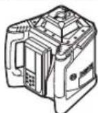
Topn30HTaBHH
peXMM
GRL 500 H/ GRL 500 HV
BepTKaIbHn
pexnm
(GRL 500 HV)
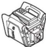
BCTAHOBITb BIMIPHOBAHNI pnpaIy TROP3OHTaHbHOMy a6o BEPTKANbHOMY NONOKEHHI Ha CTIKy OCHOBY, 3MOHTyTe HOrO HA WtATNBi a6o Ha HAcTINHOMy KpINNEHHI 593 npICPTPOEM DnBnBIBHOBAHH.
Yepe3 BnCOky ToCHiCt b HBeIIOBAAHbN BmIPIOBaIbHn npnaI dyKe yUITnBO pearye Ha CTpcaHHa 3MiHN B nonOKeHHI. Tomy cnIkyte 3a CTabINbHM nOIOKeHHM BmIPIOBaIbHOro npnAady, u6yHNKHyTH npeepNaBHn y pOboti 3 npuHn DoatKOBO r HBeIIOBaHHa.
YnpabinHHBmipIOBaIbHIMIHCTpyMeHTOM(INB.MaN.C)
YnpabnHHBmipOBaHbHM IHCTpmyHTOM 3dINCHOcTBCA3a DONOMOTOKHOKOH Ha na3epHOMy npHmaui. YnpabNIHH MOKHA 3dIHCHOBaH a6o 6eNocepeHbHO Ha BmipIOBaN HOMY IHCTpmyHtI (na3epHn pNIMau BCPTPOMHeH N CTAnu 3apAKn i 36epirAHn6), a6o 3aDOnOMTOO padio3B'3kY (na3epHn npHmau dHyKIOHOE B RKOCTI nybta DCNTAHUHOY npabniHH).


368 | YkpaɪhcbKa
Pobouciann
CnCTema,IO CKnaIaCTbC3 BVMIPIOBaIbHOrO IHcTpMeHTy I na3epHOrO npMau, Mae 3 po6oCi cTAH:
YBIMKHeHHCTaH
YciФункii BmipIOBbHOrO INcTpMenta i NaepHOrOpnIMaHa aKTHOBaHI.
INB.《BMHKaHHA》,CTOp.368.
-PexnM ouikyBaHHa
Bilwictb fyHKui BmipobanbHoro IHcPymenta deakTBBOAHi He 6 bilwe Hix Ha 2 roHN3aJn 36epexehn eneKtpoehepri.
CnCTema CnHnHaI3auii Dna 3axncty Bi kpaiaKKn i cNCTema aHTnpdey 3aIIuAoTbCRAkTHBHHM.
Yci HanaaTyBaHHa (3BkyOBn CNHAN/ryHICTb,TOHICTB BmipHOBaHHa,Haxn Too) 3anam'ATOBYOTbc. DINB.«PeKIM OUYiKyBaHHa》,CTOP.368.
-BHMKHeHH CTAH
YciФнкii BmipIOBaNbHOrO INCTpyMeNTa I Na3epHOro npnMaayaeakTbBOBaHi.
ДИВ.《ВИМнКаHH》,CTOP.368,i《ABTomaTHUHe BIMNKAHH》,CTOP.369.
BMHKAHH/HBMHKAHH
He cnpmaOByTe na3epHn npomihb haoJe i TBapHH i He dNIBITbcy na3epHn npomihb, BKNIOaOuH i 3 BeNHKOi BiCTani.
He 3aHnwaTe yBIMKHyTH BmIPIOBaIbHH npHaD 6e3 dOrrny, nicra 3akInueHH po60TH BmHKaIte BmIPIOBaIbHH npHaD. IHIi ocoBu MOKyTb 6yTu 3acinIIeHi naepHM mIpomeHem.
BkaibKa: Npeep BnKOpNCTaHHAM BmIPHOBaIbHOrO IHcTpymEtHaZbKnBuKoHyTe nepeBipKy TOnHOCTi (INB. «PipeBipKa ToHocI BmIPBOAbHo rno npHnAyn》, cToP.375).
Noataokpo6oTH
Bka3ibKa:BmipobanbHnInCTpyMeNTIla3epHN npHmau NOCTaBnIObCraYcnapeHOMByHnI(=na3epHN npMma MOKe BHKoHyBaTHyHKuII DnCTaHuiHOrO ynpabINHn).
3MeTOO 3aOuaJaKeHHeEeKTPoeHepriBMMKaIte BMMIOBaJIbHN IHCTpyMeHT Ia3epHN npHMau, NIIe KOIN 36bpaTeCb PpauOBaTN 3 HMM.
BMKaHH

U06yBMKHyTHBmIPIOBaIbHnIHCTpyMeHT, BCTPOMITbIa3epHN npMmaY cTahuio 3apAKn i36epirAHn6, nCn4 YOHaTHCHtB KHONKY yBMKHEHHB/MMKHEHH17.
a60
BCTPOMITbIa3epHnI npHmauy ctaHzio 3apdKn i36epirAHn6,a nOTIM BnMItb Noro 3 Hei. Picra yboro, uOb yBMkHyTH BMIPIOBaHn IHcTpymENT, Heo6xIDHO HATCHyTH KONky yBMKHeHHB/BHMKHeHHA17 npTgrom 30 XB.
PesynbTa
- H a n c p n e i H a k o p o t K n yac BiDoppaKaHbCn yci iHdkaTOpn.
-TOUHaTaBcAABTomaTHHe HIBeIOBaHH(INB. ABTomaTHHe HIBeIOBaHH,CTOp.371).
-CTema aHTnpey BMnKaTbCyepe30c nicn ABTOMaTHUHO T HIEBIOBAAHn(INB.《CTema aHTnpey(ADs)》,ctop.372).
Iicra yboro BmipioBaHn iHctpymEt BnnpomHIOe na3epHn npOMiHb 7 (GRL 500 H) a6o na3epHn npOMiHb 7 i npMOBCHn npOMiHb 1 (GRL 500 HV).
BmHKaHH

HaTnCKaTe KHOKNy YBIMKHeHHBbMkHeHH 17 npToTROMnp6n.2c.
Pesnbtat
-06epTaHHI pHINHReCTbCa, Ia3epHnI IpomHb BIMKHeHn.
- Yci iHnKaTOpHa nCnnei niCbiuYBaHHaHcNneBIMHKaIbC8.
Bka3iBaKa: RaKIO na3epHn npHmau i 6yIDeNBn na3ep BmKHeH, IyBIMKHeHH Heo6xIdHO 3HOBy BCTPOMTN na3epHn npHmau y cTaNIO 3apAKn i 36epirAHN6.
Pexhm ouikybaHHa
3a donomoroI naepheHOr npnMaay BmipBoBbHn IHCTpymENT MOxHa nepeBecTN y pexHM OiykBaHHa He 6JIbhe HIX Ha 2 roHNH.

-ⅡIyBIMKHeHHpeXMyOuyiKyBaHHHaTnCHITb HA KHOIky peXMy OuyiKyBaHH 21.

ypeKIMOuykyBaHHHaIa3epHOM npHMaui oRpHTb IHdkatop pexkMoy oukyBaHH 441, npn AKTNBOAHINCTEMCNI HAIJIa3aII DIA3axHCTY BID KpaJIKHIOdaTKBO OropHTb IHdkATOP CInHAI3aIII DIA3xHCTY BID KpaJIKK 36.

PnA KTHBOBaiH CNTEMi CnHrHanl3auiDn3axHCTy BID KpadiKHa BmipIOBaIbHOMy IHCTpyMeHTI MIRAE CBITNOJIOc HrHanl3auiDn3axHCTy BID KpadiK4.
Yci iHui iHnKaTopi na3epHni npomHbBMKHeHi. Cntema aHTnDpeHy 3aHnuaTcBc yBmKHeHOU.

-ДиВnxOу3peKMyOuyiKyBaHH3HOB HATNCIb KHOKNy peKMy OUYiKyBaHH 21.
PexHM oukyBaHHB BMKaebcABTOMaTHUHO,AKUO npTROM 6Ibwe HIX 30 XB.Na3epHn NpOMiHB He npoxoHTb Kpi3b PnHMaJIbHe BIKOHue 26 a6o npOTARom 6Ibwe HIX 30 XB. He HAthCKAIObCnKONKn Ha Na3epHOMy npHmaji.
BkaibKa: Kaio naeepn npmMa 6yDBeHbHn naeep 3HaXoIaTbCrypeKMI OUYKBaHHIOBWe HIX2rOHNBOHOBBA ABtOMaTHUHO BIMHKaIObC. Iy yBIMKHeHHH He06xIDHO 3HOBy BCTpOMHTn Naeepn npmMa y cTaHJIO 3apAKn i 36epiraHHN 6.


YkpaHcbka 369
CTaHdApTHe 3aBODcKe HanaWtBuHaHa:
[Функи рекиу OчkyBaHH DeakTNBOBaHa].


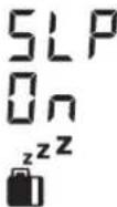

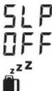
-ДлувIMKHeHHФункii pexMy OUIKYBaHHOДнОчACHo HATINCHiB Ha yBIMKHeHOMBy BmIPKOBaJIbHOMY IHCTpyMEHTI KONKY yBIMKHeHH/HBMKHeHH17 i KHOHkypeKMy OIKyBaHH21iNOTPMAHTe IX npOTARom Pn6N 2c.HaHcPiNEpTOrAMrPn6N.3C BIDOp6paKaTaCbra HOBNI CTAN [ФункiipeKMyOuICyBaHHA AKTIBOBAHA-SLPOn]иIHINkATOPpeKMyOuIKyBaHH44
PnBMMKaHHi Ce HalaWtYBaHHHe 36epiraetbCn.BMipIOBaIbnHInIcTpyMeHTaBKnDnBMKAeTbCn3BMKHYTOIO fyHKciOpeXmMyouKyBaHH.
-ДЯВIDKIOUeHHeФYHKuIIpeKIMy OUYBaHHOJHOUacHOHaTNCiB Ha YBIIMKHEHOMBYBIMIPKBaBbHOMYIHCpMy MEHTI KONIKY YBIIMKHEHHe/BIMKHEHHe 17I KONIKY peKIMy OUYBaHH21 i NOTPMaHTE IX npOTARnPn6n.2c. HAnDneI npOTARm Pn6n.3C BIDOpPaxaETCBa HOBN CTAN [ФунКИpeKIMy OUYBaHHDAEAKTNBOBaA=SLP OFF] n IHINKATOPpeKIMyOUYBaHH44
ABTOMATUHE BHMKHAAHHA
3a neBnX yMOB BmIPBOBaIbHn IHCTpyMeHT I na3epHn npMaay ABtOMaTHNO BmHKaOTbcra (pe3yNbTaT nB. «BmHKaHHA, CTOp. 368):
BmipobalbHH IHCTpyMeH Tnoa 2,5roHH 3hAXoDHTBC3a MEXKaAMCamaOHIBeIIOBAHH I NOMINka 3 BiIOBIDHM KOOM He ycyeHa (DNB. «YcyHeHH HecpapBHOCTe》,CTOP.379).
-πρnakTNOBbAHOMypeKmOiyKaBaHHBMMipOBaHIN IHCTpyMeHTHEBMkAcTeBcA DOBHe HIX2rOHN.
- CnCTema aHTHpey yBIMKHeHa npOTaROM 6InbSe HIX 2,5 roHH.
-BHMIPOIBaBHHI HCTpyMeHT 3haxOHTbC8a Mekamn dianasaohy po6ooyi tempeatypn.

IpeaabTomauHM BMMKHeHHB MIPBOaHbHOIOHCTpyMeHTa i na3epHORO npMaHa Ha dOaay Do 3ByKOBOcRnany np6n.5 cMrae IHNKaTOp BxOy 3a Meki Do3BOJeHOToemnpatypHOro dianaoHy 34.
IicraabTomauHOrOBmKHeHHa:
-3a nontpe6n 3auekaTe, nOKn BHMipIOBaIbHn iHCTpyMeHT i na3epHH npHMaH He NOBepHybCra Do dianaoHy po6ooyi Tempepatypn.
- y paai Heo6xHocTi 3HOBy BCTaHOBt BmIPBObHN IHCTpyMeHT y 6aKaHe NOIOKeHH i 3HOBy BBIMKHITb Ioro.
БатAPEка рально уacy RTC (Real Time Clock)
Kkuo nicra yBimKHeHH HndkaTOp ITebpany Kani6pyBaHH 35 Mnae np6bn.10c, cina 6batapeKa peaIbHoro Yacy RTi B6ydoBaHn AkmyTApOp po3paHBCn. ITePbaN Kan6pyBa 6Ibwe He BiDCTeKyeTBcn.
-3BepHITbCBABTOP3OBaHycepiCy MaicTePHo Bosch.
CnHaniiaaia dna 3axncTy BiKpaiaikkn
IynonepeJKeHHKpaIikOKCNCTema,IOCKnaIacb3 BmipHOaJIbHOrOInCTpyMeHTaI na3epHOrO npnMaay, 06NaHaHa DbOMa 3axNCHMm MexaHi3MaMm:
-BMIPIOBAIbHM IHCPTpMeHtOM MOXHa ynpaBnTH NIIe 3a DOnOMoTOI Na3epHOI npIMMa; NaHEI ynpaBNIHH HA BHMIPIOBaIbHOMY IHCTpMeHTI HEmAc.
-ПиВДДАЛHИВИМIPIOBAIbHOI INCTpyMeHTa BID peNepHOI TOKIN HA BVIMIPIOBaIbHOmy IHCTpyMeHTiHa Ia3ePHOMy npMauCnpaBObYE RA 3ByKOBA,Tak i CBITNOBA CnHAnlizua.
YbIMKHeHH CHrHaI3auiI dnn 3axncty BiKpadiixkN
CtahapThe 3aOdbke HanaWtyBaHHA
[ChTeMa CnHnI3auii dIy 3axNcty BiKpadiKkBHMKHeHa].

-ПиуВIMKHeHOMByBMIpOBaIbHOMy IHCTpyMeHTI HATNCHITb KONKу CTHaII3aII dIa 3axnCTy BiKpaIIXKN 22.CHCTema CTRHaIIaIeIINIg 3axnCTy BiD KpaIIXKN yBIMKHeHa.
InnkaTOp CnHnIauii Dn 3axNCTy BiD KpaJixK 36 iCBITnoiOcnHnIauii Dn 3axNCTy BiK paJixK 4 CBITbCn.
PnBHMKHeHHI CNTeMH CNHAni3auiI IIN 3axNcty BID KpaJIKKN HanaWtYBaHHA 3anam'TOBYOTbcn.
IINBIMKHEHHIpyBIMKHEHOMBYBMIPBOBaHOMY IHCPTyMeHHTHaTNCHTb KHNKy CnHnlaaui Dn3axncty BiKpaJIKN 22.
PnKnadn BnKopncTahnn CnHnI3aui Dnna 3axhcty BiKpadiixk
PnKna
BMKOPNCaHHA
BmipobalbHn IHctpyMeHT yBMKHeHn.
a60
Bmipobalhni
inctpymenty
pekmi
oukybaHH.
3axchmMexaH3M
CNCTema CnHai3aui akTMBObaHa

IINKATOP CnHAni3aui DnA 3axNCTy BID KpaJikKn 36
TOPHTIOCTIINHO

CbitnoiO cnHnIauiiDn 3axnctyBjKpadiXKN4Ha BMIpioBaHOMY
iHCTpymehTI NOBINbHO 6NnMaE


370 | YkpaɪhcbKa
PnKna
BKNOPCTAHHA
BIMipOBaIbHnIHCTpyMeHTBMKHeHn.
JaasepHnnpmMaBMMKHeHn i HeBCTpOMNeHnyCTaHIO3apAKn i36epirAHn6.
3axnchm MExaHizM
CnCTema CnHrHanlaaui DeakTHBOBaHa IHNkATOp CNHrHanlaaui DnI 3axncty Bi, KpaJiKKn 36 He biObpaKaεTcB
Cbitnoio dnrHaniaui nna3axncty BID Kpaixk4 Ha BMIPOBaBbHOMY IHCTpyMeHTI He rOpNTb
KIOBIMIPOBaHbHIN IHCTPymENT npy yBMkHTi CNrHaI3aIpyd 3axHCTy BID KpadiXKn BiDAnAETbcB iAD kTAYbHorO Micu 3hAxOxJHn DOBHe Hx Ha 5c, CnpauBoBye CNrHaI3aIua:
HaBnMIPOBaIbHOMy IInCTpyMeNTi HaIa3epHOMy npHmauI nyHae 3ByKOBn CNrHaI.
A-3BaKeHH pIeHb 3ByKOBOrO TnCKy BID 3ByKOBOrO CnHany CTaHOBHT do 110d(A), Horo He MoXHa perYnKoBATM 3MHOIO rHyHOCTI 3BuAAHORO 3ByKOBOrO CnHany.
He TpMaTe Na3epHn npHmau 6nH3bKO do Byxa!
BciyHKuO6cnyTOBaHn8bokyOBca.

-Cbitnoiod cinHaniaui nn3axncty BiKpaJixk4Ha BmipioBaIbHOMy IHctpymeHTiWBnKO Mnae.
-ⅠнкаторсганиацдязхстВд КаджКЗ 36HaIazephOmynpHmauMnrae.
-Дя BHMKHeHHcHrHaIaui,IO cnpauObana, HATNCHTb KONKy CnHrHaIauiDn 3axHcty BiKpaJixkN22.
3ByKOBn CmTHaI npnnHReTbC.
Bci cyHKuiynpaBmHnpo36IOKOBYtBc.
Pn yBIMKHeHHi Yci HanaaHTyBaHHN NOBepaIOTbCn OCTaHapdTHNX (INB. «BMKaHHA», CTOp. 368).
Cnctema CnHnai3auii DnI 3axnCTy BiD KpaiaKKn 3HOBy aKTHBYcBcR.
IIndkaTopn nepeBipKn kani6pyBaHHa
(nonepexdxhenn npo npoyuwehna Kani6pyBaHn)
Ktpe6a nepeBipn KaIbpyBaHHB HmipBoHOro IHcPymETy, BOHO BIDobpaKaAcTbca Ha DCnnei BmipOBaHOrO IHcPymETy nCnY yBMkHeHHa PI3HMn IHnkatoamny KOM6Haui 3 IHnkatoPOM «CAL».
Bka3iBa: Iicnne npworo 3anycky B ekcnnyatauio daTtKN nonepedkeHH npo npuyehHH Kani6pyBaHH (IHTepBAN kanibpyBaHH, tempepatya 3epiarHH, ctpyc BMIPOBaHOrIO hCTpyMeHa) yBMKHeHi.
Poka3aHHnDcnnne
PmHnHa
PonepeJxHn npo npuyen Hn kani6pyBaHH

roptb
IHTepBan Kani6pyBaHHa (KoKHi 12 MicraJb) 36ir.

IINKAtop iHTepBany kanibpyBaHH 35 roptb
PokaazHHnDcHnne
Pnunna
Ponepejxennn npo npuyennnn Kanipybann

TopMb

IHINKATOP BNXOy 3a MEXI DO3BONEHO TEmnepatypHoro DianasonHO
34 ropnTb
Bmipobalbnn
Inctpymert 36epirabc
no3a diaana30HOM
do3BOHeHOi
Tempepatyn
36epirahn.

rOpHTb

IINKATOP nonepdkenn npo ctpyn 38 ropntb
BmipobbHn IHcTpymENT OTPMAB 3HaHnCTpyc (Hanp.. BapnBCa 6PiIy np naHHi).
IIndkaTOpHnepeBipKnKaiibpyBaHHraopbHeIDOBRO,NOTIM 3ragaOt b13HOBy BiDobpaKaIOBcNnue npy yBMkHEHHI.
PnXOByBaHHI INdkaTOpIB nonepeJxehHn npo npuyenHn KanipbyBaHH
E MoKJIbIcIb npHXOBaTH UIHINKaTOpN Do THX nip, NOKI 3HOBy He 3'ABNTbCn pInuHa dIg NonepeJKeHH npo npOpyuHHe KaIIbpyBaHH.

-ПдчсВдОбражнн nonepeckhen npo npoyuHnKanibpyBaHHaTnCKaTe KhoNky KaibpyBaHHa 25npotrOm np6bl.2c.
IINKATOpn nepeBipKn Kani6pyBaHH BID06paKaKoTc3HOBy,NIWe KOInN3'ABnEeTBc npuHa dIg NpopeJxHn pO npOyHeHH KANI6pyBaHH.
PeKoMeHDoBaHn NoprdoK diN icNn NobiDomHeHn npnepeBipKy kanibpyBaHH
KpOx.
STOP.
1 PepeBipTe TouHicb HIBeIOBaHHa 375
2a BiodxHnEHHa 30 M3hAxOoDbc y Mexkax MaKcMmaIbHO do3BOJeHHx 3HaueHb ±3,0MM: npixOBaIte iINKATOpn nonepdKeHHn Ipo npoyeHHKaIbpyBaHH 370
2b BiOxHHeHHa 30 M 3hAxOoHtbcra no3a MekAMMakCMmaNbHo 03BOJeHX 3HaueHb ±3,OMM: BiKanIbpyte BmipIOBaHn IHcTpMeHT 376
3b NpebeipTe TOUHCTb HIBENOBAHN 375
4bПICNAKANIBPYBAHNNBIDXHNHEHA30M 3HAVOXOHTBCyMEXKAXMAKCHMaJIbHO 03BOJENHX3aueHb±3,0MM: MOKHNA PpauOBaTH6e3BPTaTHTOHOCtI.
IicnKaIbpyBaHHN BIDxHHeHH Ha 30 M BCE
ue 3HaXoDHTBC NO3a MeKAMMakCMMaJIbHO
do3BOeHNx 3HaueHb ±3,0 MM:
BIIaIte BIMPiOBAJIbHH IHCTpMent Ha
nepeBipKy do cepBicHO MaJcTePHi Bosch


1609 92A4DX|(28.3.18)BoschPowerTools


YkpaHcbka 371
Pexhmnpo60TH
JinHoceiXiY
IiHcOeX iY no3haeHi Ha Kopnyci HApotauiHOI TIOBOKOIO.
PotaüHHm pexHM
BmipboabnHnIHCTpymert npaueo3 noctiHOU WbNdkicIO o6epTaHHa (600XB^-1) ,npdaTHOIO nI BHKOpNCtAHHa naeepHOro npimMaqa.
Ornay pexhmib po60tn
- ABTomaTHHe HIBeIOBaHH
nicra yBIMKHeHHn/niJ uac eKnnyatauii - pexHM HIBeIIOBaHnHa y3DObK OdHoiOci
-pekncpeepnioiH
-cnctema aHTnpen y(ADs) - niiHnHH pekm y BepTkKaIbHOMy peKmi (GRL 500 HV)
ABTomatnHe HIBeIIOBaHH
ABTomatnue HibenIObAHnnicnyyBimKHeHH
IicnBmKahHBMIPIOBaHbHINHCPTpMHTnepeBiprc Trop30HTaJIbHe NIOXeHHI aBTOMaTHHO KOMIEHCyE HEPiBHOCTI B Mekax Diana3OHy ABTOMaTHHO HBeJIIOBaHH 6N.8.5% (5').
IiD uac HIBeIOBAAHH MHRae iHnKAtop nonepedxKeHH npo HIBeIOBAAHH 37.
GRL 500 HV: Iicna yBIMKHeHH BnMIPIOBaIbHn IHCTpymeHT camOCTiHo pO3ni3Ha e RopN3oHTaJIbHe a6o BePTHKaJIbHe noJoxHeHH. U6 3MIHNr BePTKcJIbHe noJoxHeHH Ha rOpN3oHTaJIbHe a6o HABNaK, HenOTpiBHO BmNKaTI nIHCTpymeHT.
AbTomatnue HibenIOBaan n iac ekcnnyatau
Kiio nicra 3mHn noIOKeHHB HMIPOBaHbHn IHCTpyMeHT 3hAxOHTbc3a MExKaMn Dianao3oHy caMOHBeNIOBAHH np6bl.8,5% (5^) ,ABTOMaTHuHe cMOHBeNIOBAHH HEMOXINBE iBIDobpaKaTeBC KOD NOMUNK (JNB.《YcyHeHH HeCnpabHOcte》,CTOP.379).
Iicra HBeIOBaanH BmipOaBbHn IHcTpyment NoctiHo nepeBipae CBOE Ropn3oHTaNbHe NIOKeHH. Ppi 3MIHI NOIOeHHA BtOMaTHNO BHKOHyCTbC HIEBIOBAHN. IaI 3anoBirAAH NOMIKAM PnB MmipOBAHHi OeptAHN IaepHOrO IpomHa BmKAcTbCn iD qac npoeUp HBeIOBAHH.
PexHM HibenIOBaHNy3dOBx OndoiOci
Ipn ropn3oHTaBHOmy nOIOXeHHI BmIPIOBaNbHOrIO HcTpyMeHa y peXMI HiXnIy No OOnH Bici aBTOMaTHHO HIEIOCTCBiCb X.
Плошины obeptaHa MoxHa NOBepTaH HABKONo Bici X y Mekax ±8,5%.
Bka3ibKa: 3a notpe6n Hala7ybatn KyT haxny o np3y nicn yBIMKHeHH, Heo6xioH0 3aueKaTH 3akIneHH ABTomATuHOro HIEJIIOBaHH (INB. ABTOMAtuHHe HIEJIIOBaHH NICN YBMKHeHH, CTOp. 371).BOHO 3ano6irac BnHHKeHHHn HnPaBnIbHnx pe3ynbTaIB BmIPOBAHHa.
HanaityBaHHKa KyTa Haxnny
HanaTByBaHHaTa HaxnMy MoKInBe y MekX ±8,5%.

HaTCHITb Ta TpIMaIte KNONky Haxnly 18 a6o 20, nOKn Ha DCNnei He BiO6pa3ntbC8 baxaHe 3aueHHa Haxnly.
Bidnycttb KhoNky Haxnny 18 a6o 20.


IiD qac HanaaHTyBaHHK KyTa Haxnny MInrac iHINKaTOp NonepeJxKeHHN npo HBeNIOBaHH 37.
IINKATOPpeKmMy haxmy41 ropntb noctiHo.


Auto
HaHTCHITb ODHOaCHO KHOIKN HAXINy 18j20. HanaWtyBaHHa KYta HaxNtY BmKHeHe.
ABTomaTHne HIEJIIOBAHHYbIMKHeNE(INB.
《ABTomaTHne HIEJIIOBAHH》,CTOP.371).


Ypa3i nepeBnueHHaIana3OHy haxny B ±8,5%, iHnKaTOp peKmMy haxny 413raacE iBIO6paaeTbcN KOJ NOMNIK (DNB. YcyHeHH HeCnpaBHOCTeN), CTOp. 379).
Pexm cepenhboi nii (nB.MaI.D)
YpeKMI cepEhBoi liHbBmIPHOaBbHn iHcTpMeHT HaMaTaCTbCABTOMaTHO 3HaHTu cepEHIo NIIHO Na3epHOrOpnIMaHa aNIAxom NiHHTTA aObo onyckAHn poatauiHOI TOnOBKN.

-HaTHCKaIte KHOIIkypeKIMyueHTpAnbHOJIJI 19poTAROMnp6n.2c.
POnHnAeTbCnABTomAtuHnpyx potauiHOI TOnOBKn BROPY-BH3.
NowyK:
- PotauiHa roIobKa nIHImaetbca Do kiHra Bropy.
2.BMnKaETbcra na3epHn npomHb.
3.PotauiHa ronOBKa onyckaetbca DOHN3Y.
4a.JaasehHn npomHb nOtpanHe y npHmAbhe BIKOHue 26 i3haxoHtbcpeeHIO liHIO. a60
4b. Na3epHn nPOMiHb He nOTpanIe y npMmaJIbe BIKOHue y diaa3OHi HaxNHy; BiDobpaKaTeC KoD NOMInK (DNB. 《YcyHeHH HeCnpabHocTe》,CTp.379).
IiD qac nouyky cepenHboi niHIT Mrae iINKATOP nonepedxehn npo HBeNIOBaHH 37.
IINKATOPpeKmYueHTpaBHOJIHII 42 roPntbNoCTiHo.
3 MOMHTy NtpanHnHn NaepHOro
IpOMeHr Do IprnMaHbHO RbIO BIKOHr26
Do 3NaXoDkeHHa Cpeedhboi NiHII NyHaC
CKPeKoTnBnB 3Byk.


372 | YkpaɪhcbKa
UbndkctbypuypoatauihoirolOBKnynobInhHcBcra,AKTinb Kn a3epnhnpomihnoTpanney npmaIbnHe BikoHc26. Iicna 3haxoJxehn Hcepehdboi nii BNmipObaIbn HcTpMeHT ABtOMaTHO BmHKAc pexHM cpehdBoi niHII. HanauTOBaHH hAn3anamTTOBycBc i BIO6paXaTbcra Ha dncPiE.

-Дпгперьанн ржиму српаль hoi liHii nia qac noWky haTCHiB KhoNkpy pexnmy cepenboi liHii 19.
a60

OHOaCHOHaTnCHITbKHOHKnHaxnny18j20
yBIMKHeHHABTOMaTHHOro HIBeIOBaHHA.
Auto


PnWbHdWeHH nowyky cepedhboi nihII na3epHoro npHmaya
PnoyKepeHb0i niiHaepHOro npHmMa4 3abXn nouHaebc3 pyx yotauihoI roNobKn Brpy. Kaio naepHn npomHb 3haxOHTbcn iD cepeHbOIO nHieIO i He NotpanHB y npimMaJIbHe BIKOHue NaepHOro npHmaya, MoXHa HapabTH pX npaepHOro npomeH y 3BOPOTHomy HanpRMky.

-HatncKaTe KhoNkypeKmY ceHtpaBHOIiHII 19 npotrarom np6n.2c. POnuHaCTbCABTOMaTHHpyx potauiHOI rONOBKN BROPY-BH3.
-HaTHCHITb KHOHNY HAXNny 20. PotauiHa roNoBkA onyckaetcbn DOHN3y.
cnCTema aHTnpei (ADS)
Bmipobalhnn iNCTpymEn 0bnaHaHH nCCTeMOAHTNDpeHpy, kAp npn 3mHi nONOKeHHa 6o CTPyCaXBMIPOBaHBOI HO INCTpyMeHa a6o npn Bi6paui rpyHTy3an6ira c HBeHNbAHHO Ha HOBI BNCOTi, a OTKe i NOMNI BWCOTH.

CnCTema aHTnDpey BMnKaETbcaYepe3 np6n. 30 C nCnryBIMKHeHHBmIPkoBaIbHoro iHCTpyMeHTa.
IiucBIMKaHHNOBINbHO Mrrae IHmKATOp nonepeKeHHnpoCTpyCH3. Iicra yBIMKHeHHa ue IHmKATOp rOHTb NoCTHNO.
CnCTema aHTnIpeHcy CnpaBObyE, Ako BoepTknAbHe NOIOKeHH BnMIPHOBaHBO IHCpymeHa 3MiHOeTbC a60 RaIO peCTpyETcBc HbN Chpyc: OebpTaHH Naepa npINHReTbcIMrAe IHNkATOp NonepeJxEH NPO CTpyCN 38. DOnaTKOBO Ha NaepHOMy PnIMMaI IpOTAHo 5 cNyHae CKPeKoTNBn 3ByK.

-ПиВИMHKHeHcCTeMiaHTnDpeФHy HeHaIOBRO HATNCHTb KHOKNy yBIMKHeHHra/BHMKHeHHra 17. ПОИнlaCTbca ABtOMaTHuHE HiBeNIOBaHHra(INB. «ABTOMaTHuHE HiBeNIOBaHHra NiIq Yac ekCnIpyataJIi》,cstop.371).
- IpepeBipTe BnCOTy Na3epHOrO IpomEnHa No pepeHri ToUci i ckopinyte 3a noTpe6n BnCOTy BmIpOBAhBOr IHCTpyMeHTa.
BmHKaHHH cHTeMH aHTnDpeHf
CnCTemy aHTnDpeFy MOKHa BmMKHytn niqac ekcnnyataui BmIPHOBaHbHOrIO hCTpyMeHtA.

HaTCHITb KONIKy YBIMKHEHHB/HBMKHEHH 17. CnCTema aHTNdpey BHMKaETbcA.IHdkatop nonepdKeHH npo cTpyc386inbwe He BiDobpaKaETbcA.
PnBIMNKaHHiZe HanaHTyBaHHHe 36epiraTbcN. BmipHOBAhHn IHCTpyMeHt 3aBxDN BMkAcTbc3 yBMKHeHOIO CNTeMOO aHTNDpeHy.
linHHnpeXHMyBepTKKaIbHOMypeXNMI (GRL 500 HV)
YBepTKaJIbHOMI NOJXeHHI BHMIPIOBaIbHOrO IHCTpyMeHTA nIOUHy OeptanHa MOxHa po3aUyBaTH y3DObK OCI XnnpocToI nepeBipKn ToOK 36iry a60 npaneIbHOrOBuPIBHOBaHHA.

-ДЯ NOBepTaHЯ ПLOUHIN OepeTaHHa 3a ROHNHHKOBOO CTPIKIO HATNCHTb KHONKY HAXNY 18,ДЯ NOBepTaHHa POTN ROHNHHKOBoI CTPIKN - KONKY HAXNY 20.

-HaTHCKaIte KHOHkny peKmHy ueHTpaIbHOIJIHII 19 npOTrOM np6bn.2c. NouHaTeBcA ABToMaTHnHHpyx pOtauHoi IOnOBKn npabOpuy/nIBopyu.
Pouyk:
- PotauiHa roIobKa pyxaetbca do kiHua npaBopyu.
2.BMkaetbca na3epn npomihb. - PotauiHa ronobka pyxaetcna niBopyu.
4a. Na3epHHn npOMHb NotpanJIe y npHmAlbHe BIKOHue 26 i3haxOoHT bcpeHIO liHIO.
a60
4b. Na3epHn npomih He Notpanne y npinMaIbHe BIKOHue y diaa3oHi Haxnly; BiO6paKaactcKoI NOMKn (INB. 《UcyHenHa HecnpabHocte》,CTOp.379).
YkpaHcbka 373
Piuc nowkycepeHb0i nHII Mrrac iNikatop nonepeXeHHn npo HIBeIOBAHH 37.
INDAKATOPpeXMyueHTpaIbHOiNii42 TOpNTbIOCTHNO.
3 MOMHTy notpannnHnnaepHOROpomehnDo npnmaIbHO RIO BIKOH26 Do 3haxoJKeHHa cepdHbOI niHII NyHaeCKPEKOTNBIN 3BYK.
UbnkictbpyxpoatauihoIroNOBkyoBnIyOBInbHOCTCBsA,AKTINKnnaepHnnpomHbNoTpanncy npmMaJIbHe BIKOHe 26. Iicna3haxodKeHHaCepeHbOI niHII BmIPoBaHbHN IHcTpymEt ATOmatuHOb HmNKaC pexHM cpeHbOI niHII.

PotauiHa roIOBka aBTOMaTHUHO pyxaeTbC npabOpuy.

-HaTnCHITb KHOHkny Haxnny 20. PotauiHa roNoBka onyckaetcbcn DOHN3y.
IHdkatop BihochoBHCOTn (Hb.MaF)
+30.0mm
BiDCTaHbMIXIINOuHIOoBepTaHHi cepeHbHOIinieBOiD6paKaεtcbHa IaCnneiyabcoHOTOMy3aueHHi(y[MM] a6o[IOHmax]).
INB.TAKOK《HanaWtyBaHHI INNkaJI OHNHb BmipHOBaHH,CTOP.378.
Po6ota 3 JanaeepnHm npnMaayem
Ira 3haxoJxHn Ia3epHoro npomeHa npBmipObaHHnx npocTo He6a a6o y BENKHX npMIeHHX BNkOpCTOByTe Ia3epHn npImay.
-Po3aOByTe Na3epHn PnHmau TaKHM YHOM, 06b Na3epHn PpOIMbMir DiCTaTcN PnHmAbHOrO BIKOH26
Pao38'30K mix BmipioabnHm IHctpymeHTom i nybTom HCTaHuiHoro ynpabnHH/na3epHM npHmayem
3rIHO 3 HanaHTyBaHnMn 3aBody-BnPo6nKa HanaHnnaepnnpMaay LR 50 uepe3 be3dpotOBn 38'3OK npaOe B AKOCTI nynbTa DnctauHoro ynpabninHnBmipIOBaNHO IHCPTpMeHa.

-InikKatop pao38a3ky 33 BiO6paXaeTbCra i CbiuNTb npo yHKUIO NyIbTa IINCTAHUHOR OynpabHHna3epHOROpnMaua.
IIO BIMIPBOAbbHOro IInCTpyMeHTa MOKHa nIDKnIOuHTn TaKOx
IeKINbKa Ia3epHnx npMauiv LR 50.
-BMNKHTb BmipIOBaIbHn IHCTpyMeHt I na3epHn npMau.
- BCTPOMITb DOaTkoBn Ia3epHn IpnMau y cTaHIO 3apJKn I 36epirAHn6.

-HaTnCHiB KHONkYyBIMKHeHHR/BMkHeHHR 17.

-1HnKatoppao3bA3ky 33BiodpaXaetbcn i CbiuHTb npo yHKUIOyNbTaIINCTAHIOHHOR ynpabinHna3epHOrO npimMaua.
-BnMItb na3epHn npHmau 3i ctaHui 3apAnk i 36epirAHHa. IicnaBoTo, uO6 yBIMKHTN BHMipOBaHbHn IHCTpyMeH, Heo6xIDHO HATCHyTH KONIKy YBMKHeHHBUMKHeHH 17 IpOTROM 30 XB.
BkaibKa: KaOo DO OJHO BmipobalhoIHCpymeHa nkiKIOUeHI deKINbKa naepHn npImaiv, IInue octanHH iNkIOUeHH naepHn npImau npaoE BAKOCTI NybTa nctAHUIHO ynpabinna. IHsi naepHn npImaui e NInue naepHMn npIMaaynn.
HanaTuBaHHa, Taki Ka ToHicb BmipBoHH a3ByKOBn CnHaI, MOKHa BCTaHOBIOBAtn Dn KOKHO Na3epHOro npMaua IHNBIyAalHo.
Kkuo BmKhynIa3epHn npMma, kN cynye nybTOM nctaHuiHoro ynpabInHHBmIPBOaBHN IHCTpymET TAKOX BmNkAeTbCa. DodaTKOBI na3epHi npMmaI noTpi6HO BmNKaTH KOKHNI OKPemo.

PnBtpaipapio3B'3ky HaDpaay Do 3ByKOBOCnHanyMrae iHnKaTOp pao3B'3ky 33.
LcBk3ayeHaTe,ioiHnkaTOpnnonepdKeHHa (Hanp.npoKpaIjKy,aHTnpdeF,KanibpyBaHH) He BiodbpaKaTHMyTbcra,BIMIpHObaJIbHM npnaOM HEMOxNBO 6bnbe KepyBaTH dntaHIO.
Bka3ibKa:YbIMKHyTH BmMKHyTH peKHM oukyBaHHBmIPHOaIbHORo IHCTpyMeHTa MOXHa JINHe HaTHCHyBUNKONky peKHMoukyBaHH 21 Ha na3epHom npnmai,KnDiE B KaOci tynbTa DuctanuHOro ynpabnHn.
HanautybaHH 3BykoBOrO cHany/ryhocti
IINHnKauiI NOJKeHHHa IaepHOro IpomHeB INPIMAbHOMy BIKOHU 26 MoXHa YBIIMKHyTN 3ByKObN CNIHAN.
Moxhna o6paTH OINH 3 DOX pIBHIB rYHOCTI a6O BHMKHYTH 3ByKOHN CnHAn.


374 | YkpaɪhcbKa
CTaHapTHe 3aBOJcKe HanaWbAHnE [HOpMaIbHm 3ByKOBm CnHnA]

-HaTnckaIte KhoNky 3BykoBOrO cnHany/ryuHocti 24, nOKn He diJneTe do 6axaHOro HanaawTyBaHH.
HMaC IHdNkAtopa:3ByKOBu CnHaJI BmKHeHm

HOpMaIbHn3ByKOBnCnHaI
HanautyBaHHa 3BykoBOrO cHany/ryuHocti 36epiraetbc npn BmHKaHI.
Bn6ip hanaawtybaHH iDnkaTopa cepeHboi nii
Moxha BCTaHOBHTN, RA TOUHICTb NOIOXeHHNa3epHORO npomeHa y pImMaHbOMy BIOKHc BiIO6paKaTHMeTbCRA, K《CEpeHc HanaaTyBaHHA
CTaHdApThe 3aBoDcBKe HaNaWtYBaHHe
[TouHicTb BmipioBaHHA «CepeHc HanaHTyBaHHA/3MM].

-HaTnCKaIte KONky HanaWtYbaHHaTOHOCI BmIPIOBAAHH23,NOKHeDIDTeDo baxaHOrO HanaWtYbaHH.
PnKnad Ha dncnei BiO6paKaAeTbcA cyinih
TOUHOCTI BMMIPIOBaHHA TOUHe HanaHTyBaHHA》/CEpeHc HanaHTyBaHHA》/Tpybe HanaHTyBaHHA i TOUHe 3HaueHHA.
PnBMMKahHI HanaaHTyBaHHaTOHcOCTBIbMIPOBaHH 3epiraactbcra.
IINKaToPn HAnpMky
Ponokhenna3epHoro npomeHa y npnMaIbHomy BikoHci 26BIO6paKaTaBCa:
HaDnCnnei 15 Ha nepeHbomy i3aHbomy 6oui naepHoro npnmaa 3a doNOMOIO IHNKATopa HAnpmy «NaepHNI pomih had cepedhboio NlHiEIO 39, IHNKATopa HAnpmy «NaepHNI npomih nbicpeedhboio NiHiEIO 40 a60 IHNKATopa cepeHboi niHii 43,
onioHaIbHO 3a donoMoROIO 3BykoBOrO cnHany.
Ja3epHH npHmau po3aWbAHn 3aHaTTo Hn3bko:
KJIO na3epHn npOMHb npOxOHTb KpIb BepXHO qactHy npIMaHbO BIKOHU 26,3aOropETbCnIHdkATOp HApmy «Na3epHn npOMHb HcpeDHBIO NHIeO» 39, INo3HTNBHe 3aueHHn IHdKaTopa BiNHOCHOT 32 BkA3yc, HacKinbKn nOtpiBNO iNBeCTn na3epHn npHmauBROPy. PnpYBMKeHOMy 3BYKOBOMy CnHani NyHaC CnHAn 3 DOBHMn INTEPBANAMn.
- IpeemictbIa3epHn npHMaay 3a HaprMOM cTpiKN Bropy. Pn HabNKeHHi Do cepedHboi MITK16 BiobpaKaAcBcra NHe We KINK iHNkAtopa HanpMy 39.
Ja3epHH npHmau po3taWbAHn 3aHaTTO BnCOKo:
Kkuo naepn npomih npoxoHb Kpi3b HxNHOaCTHy npmAbHoBorIO BIKOu 26,3aropaeTcI INHKaTOP HApmy «Naepn npomHb nID cepedhboIo NHIIEO40IBIDEMHE
3HaueHHIiHKaTopoBIDHOCHBOHCOTN32Bk3yE, HACKJIbKnNOTpioHOONyCTHTNa3epHn npimMaUdoHN3y. Pn yBIMKHeHOMy 3ByKObOMy CnHAnI NyHae CnHAn3 KOPOTKNM INTEPBAJAMN.
- IpeemictbIa3epHnIpnMaay 3a HanpMOM CTpiKIN DOHN3y.Ipn HabNKeHHIO cepeHbOi MTKN 16 BIDobpaKaAcBcA NHe KINHKINHkATopa HanpMy40.
Ja3epHn npHmua nocepHnI: RaIO na3epHn npomihnpOxOHTb KpIb npHmAlhHe BIKOHue 26 Ha BVcOTicePdHbOI MtK16,3aROpTbCa IHMkATOp cePdHbOI nHI43.PnHyBIMKHeHOMy 3ByKObOMy CnHAnI NyHae NocIHHHCnTHAn.
Kkuo BmipioBabHn IHcTpyMeH npeMictn TaK, 10
na3epHn npOMiHb 3HOB BnIOB 3a MEXi pHmAlbHOrO
BikoH26, np6n.5 cMrae ocTaHHi BiObpaKeHH
iHnkatop HAnpMy 39 a6o 40.
3axncha fynkui Strobe ShieldTM
Ja3epHn npHmau 6bHaHnn eneKtpOHmH mfpBpamn dIra cTpo6ocponiunoro cBtna. Uc piBtpn 3axuHaoTB BID 360IB, uO BnHkaHO, HapnKaad, ype3 npobnckoBI CBITNOBI ciHann 6yDIBENbHN MaHH.
No3haueHHa
Ha cepenHm MItu 16 nibopyu npabopuy BiJ naephoro npnMaaya MoKHa BiIMITIN BnCOTy naephoro npomeHa, KOHN BIn npoxOHTb Kpi3b cepenHny npnMaIbHoro BIKOHua 26.
Cnikkyte 3a Tm, u6b BmipHOBaBbHn npnaI nd yac
no3haeHH 3haxoDbcT OTOHO BepTKaBHo (npn
rOpi30HTaBbOMy na3epHOMy npomeHi) a6o TOHO
rOpi30HTaBbHO (npn BepTKaBbOMy na3epHOMy npomeHi),
iHaKHe 3apy6Kn 6dyt bpoTaWobHi nO BiJHOeHHo do
la3epHOrO npomeH He ToHO.
PiicbivyBaHnHaCnner
CTaHapTHe 3aBOcBKe HanaHTyBaHHe [PiCbiuyBaHH DaCnne yBIMKHe]
KJIO npOTAROM np6n.30 c hiaki KhoiKN He HATNCKYHOCTBcA, nIDCBUYBaHH DCINNE TBMAHIE.
PnHaNTCKaHHI 6ydb-RAKO KHONKn a6o npn NotpanHnHnnaepHOrO npomeHa y npmMaBHe BIKOHue nDCBvBaHHnDCIIe3HOBY BMKaCTbCra.

-106B BMMKHTn NiCbiuyBaHHHaNCnner HaTNCHTb OHOuacHO KHONKy
YBIMKHEHHBIMKHEHH 17IKHONKY3BYKOBOOR CMHany/ryHocti 24.
PnBMMKaHHHaHaaHTyBaHHN iDCBiyBaHHaDcnnner 36epiraetbcra.
3aKpInnHeHn 3a DoIOMoIO TpHMaHa daneKoMipHO peKN (DIN.MaI.G)
3a donomoroToTpmaa daekeomipho peKn 53 MoXHa 3aKpinHn naepn npmua a6o Ha daeokomipn peu ci 6yDBeBHO rnaepa 55 (npnnd), a6o ha iHnx DOnomixkHX 3acobax uipnoHO He 6bnse 65 MM.


UkpaiHcbka375
MiHOp npKpyTb BnCyBHy pamy 583a donomoroo KpINHbHO rBNHTa 56Ha TpMaay daJeKoMipHo peKN 53.
BidiNycttbfikcyBaIbHHrBHT54,HaJIbTe TpMaay daKeKOMipHOi peKN,HaPnKlAn,Ha DaKeKOMIPHy peKy 6yIDBeHbHO rAepa 55,13HO BmIO 3aTgHITb fikCyBaIbHHrBHT54.
-3aDOnOMOrO BatepNaC57MOXHBACTABHTT PnMaY DAnekomipHO peKn 53Topn3oHTaBHO. IpekoWeHH BmIPOBaBHN iHcTpymEeN Pn3BOHTb Do HnpaBnblnx pe3yNbTaTIB BMIPOBaHH.
BcTpOMiMbIa3epHnI npHmau y BHCyBHy paMy 58.
Ipebipka toHocTi BmipobanbHoro npnay
Hactyni po60n Do3B0JrEbCBAKHOyBaTH NIIe O6pe HauyeHm i KbanidikOBAHm OC6am. PpaBnla BHKoHaHH nepeBipKn ToHocTi BmIPKOBaIbHoro npnaNy afo KanibpyBaHH BmIPIOBaIbHoro IHCTpyMeHTA NOBHHi 6yTH BiOMi.
ΦaKTopn, ξΟ BπΠHbAθ Tb Ha ToUHicTh
HaibbHnBnBcnpAaTe Temepatypa 30BHIhboro cepeobua. OocmboTEmepatpyhi KOnBaHHa,IO cnoctepiraTOCB MIPy BiDaNHeHH BIDpyHTy,MOKytb cnpuHNATBIxNHeHH NaepHOrO npomeHra.
Iopjid 30BHIHIMn yMOBAMn TAKoK i cneuPhiNi Dn IHCPTyMeHTy yMOBn (Ha np.. ctpcn a6o cnblHy yapn) MoKyTb Pn3BODHTN Do BIXnHeh. 3 uci nPnHH KOKHO rpoaY nepeiNoaTKOM pOToBn nepeBiprTe Noro KanibpyBaHHM.
BixnHeHH CtaOb NOMITHM NOUHaOH 3 DOBXHBMIPOBaHbHOI DIAHKN Pn6n.20M,Ha BicTaHI 100 MBOH Moxyb CTahOBHTyDybi a6o HabITb BuETBepo 6iNbwe3haeHH Hx npn 20M.
OckinbKn Temnepatpyhki konBaHnHa c HnBnHMn 6bn3ko Do rpyHTy, Bam Heo6xidno nouHaoun 3 DOBXnHn BmipioBaalBoHoi dIaHNK 20 M 3abXnn MOHTyBatn BmipioBaHn npnaH a HtA tNBI. Kpim TOrO, 3a MoXnHBCIO BmipioBaHn Hn npnaTpe6a BcTaHOBnBOATn B cHTpi pOboOJdIaHNK. RaIO BmipioBaHbHn IHCTpyMeHT npocci OINcaHO dani BmipioBaHH BHXoNTb 3a Meki MaKCHMaHBO Hor BIXIneHH, BVKOHaTe KanibpyBaHH (DVB. "KanibpyBaHH BmipioBaHbHO IHCTpyMeHTa, CTOp. 376) a6o BiJaute BmipioBaHbHn IHCTpyMeHT Ha nepeBipky Do cepBicHO mAcTePH Bosch.
Ipebipka ToHocTi HIBeIOBaHHy y TOpN3OHTaIbHOMy nonoXehHi
Дяп néреворь Bamnotpi6ha BInbHa BmipOBaBHaДлннKa haMiHOMypyHTI IOBXHHO30MnepeD CTHO. Bn NOBHHi BIKOHATNIOBHn CKNBIMIPOBaHbДЯ KOKHOi 3 ocEiXiY.
BCTaHOIBb BmipOBAIbHn npnad y ropn3oHTaNbHOMy nnoXeHHHa staTHBI Ha BiCTaHI 30 M BiD CTINH a60 BCTaHOIBt Horo HA TBepdy, pIBHy OCHOBy. YbIMKnHtB BmipOBAIbHn npnad.
- Picna 3akinueHHn HibenobHn npnany no3haTe cepediny naepHoro npomeHa CTHI (TOkaI).
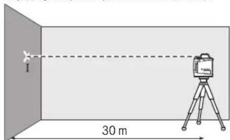
HaⅡiHn30MMAKcHMaJIbHoDOnyCTmE BiIXnHeHHA CTaHOBnTb:
30MX± 0,1MM / M = ± 3,0MM.
Takn mHOM, p3HNu d mKt Tockamn I i II npN KOxHOMy 3 o60 x BmipHOBaH he NOBHHa nepe6iNbSyBuMaMc. 6 MM.
Ipebipka Touhocti hibenobahny BepTKaHOMy nonoxheni (GRL 500 HV)
Ia nepebipkn Bam notpiibha BinbHa Bmipobalba da nHk Ha miuHomy rpyntIOBxHHO 10 m nped BncoKoO CTHO. 3akpinitshyypBCKa ha CTHI.
-3MOHTyIe BHMIPIOBALbHn npHaJy BEpTHKaIbHOMy NonoJxHH Ha 1aTbHI a60 BCTAHOBIT Ho H TaBepdy, pIBHy NOBepXHIO. YBMKHTb BHMIPIOBALbHn npHaJd i 3aueKaIte, NOK He 3aKInHtBc CaMOHIBENIOBAHHA.
BnpiHnTe BmipIOBaIbHnn npnaad Ta, uO6 naepHn npomHb TOnHO nONAB CpeHNy shhpy BAckca Ha Horo BepXhbOMy KINCI. P3HNu dMk naepHm Ipomehem Ta WHPOM BnCKa Ha HNKBbOMy KINCI Whpy -Ce BIDxHnEHn BmipIOBaIbHO npnaad By BID BEpTHKani.


376 | Ykpaɪhcbka
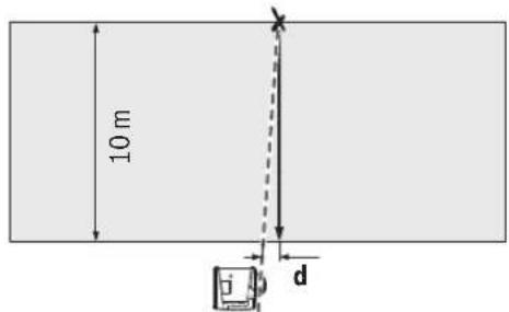
HaJINHJI BHCOTOIO 10 M MAKCMMaIbHO DOYCTHMBeIXNHeHHCTaHOBHTb:
10Mx±0,1MM/M=±1MM.
TaknMHOM,piHnue d He NOBHHa nepe6inbuybaTN MaKc. 1 MM.
Kani6pyBaHHB BmipHOBAnbHoro iHcTpymeHa
Hactyni po60tn Do3B0n8TcBA BHKOHyBaTH NmIe Do6pe HauyehHM i KbanidipikOBaHH MOC6am. IpaBna BHKOHHaNepeBipKTouHOCTi BmIPoBAJbHorO npNlady a60 KanipbyaHH BmIPoBAJbHorO IHCTpyMeHTa NOBHHi 6yTH BiDomi.
Petelbho Kani6pyte BnMipOBaBHH IHCTpymENT, a6o BiDaaTe Horo Ha nepeBipkyo do cepBchoi MaICTephi Bosch. Hetouhe Kani6pyBaHH np3BOaHTbdo HeBipHx Pe3yIbTaTIB BnMipOBaHH.
NoHHaTe Kani6pyBaHn Hnse, kNo topti6Ho BIDKani6pyBaTH BmipIOBaNH INCTpymeT. Rk TINbKN BmIPIOBaHn INCTpymeT IpeXoDnB BpeXnM Kani6pyBaHn, Heo6xIHO HeoDMInHO TOuHO BVKOHaTN KANI6pyBaHn DO KINc, uO6 HadaNl He OTPMaTH HnpabNbHi pe3yNbTaTH BmIPIOBaHn.
BkaibKa: Pcna KaIbpyBaHH iHnKATOp npeBipKn KanibpyBaHH BiO6paXaTbcra 3HOBy, Nnue KOnn 3'BAeTcbn PrnHa dnnnepeJxehn npo npuyenHn KanibpyBaHH.
JaKaiibpyBaHHHeo6xioMaTnBilbHyDINHkyMeHHiX 30 M HtBPdOmyIpyHTi nepei pIBHO CTIOIO.
3aJxKanipbpyte yci Bici (GRL 500 H: X n Y; GRL 500 HV: BiciX,YiZ).
Kani6pyBaHHBiciX
MoHTyIe BmIpIOBaIbHm IHCtpymEt y TOpN3OHTaIbHOMy NIOJKeHHHa WtATNB 63 (npunad).
- Po3aWyIe 7tAHB Ha BIDCTAHI 30 M BID CTIN. PnH cboMy B6HTnHa BmIPbAbaHbOMy IHCTpyMeHITI INDKaTOp BICI X NOBHeH 6yTH npNEHnKyIaRPHN CTHI.
- YbIMKHiTb BmIpiObaIbHn IHCTpyMeHT.


- Ondouaccho HaTnCKaIte KhoNky KanibpyBaHHa 25 iKhoNky haxny 18 npotraFOM np6bn.2c.

CmBON Kani6pyBaHnB Bici X BiO6paKaæTbc HaДиCnnei.
IiD qac abTomatMHO HIBENIOBAHH Mrrae iHnKaTOp nonepdKeHH npo HIBENIOBAHH 37.
-3auekaIte, nOKn BmipIOBaIbHn IHCTpyMeHT He npOJe HBeJIIOBAHH.
-3a donomoroknnaepnornpnmaa 3naHndtbepeendno nhiio i nepenecitb bncoty X1 cepedhboi niH hi Na CTHy.
-Поверпь ВИМIPКВАБНИСТРМЕNT Ha 180°, He 3MHIOHUN BNCOTU STATNBA.
-3aekaiTe, nokn iHdkatop nonepekeHH npo HIBeIOBaHH 37 nepecTaHe MrgaTHi BmipIOBaIbHN IHCTPymeHT He npOJe HIEBIOBAHH.
-3a donomoroo naepnro npnmaa 3nai itb cepeHIO nHHIO i nepenecitb HOBY BncoTy X2" cepeHboi niHII ha CTHy.
-3haiitb toHy cepenHy mix cepenHimn nihmX1 i X2]ipo3auyte Ha hi naepn npnmau 13 cepehboHO mIKIO 16.

HaTCKaIe KhoNky Haxnny 18 a6o 20, nOKn IHdNKatop cepedhboi liHii 43 He noUhe ropiTH noCTiHNo. PpYBIMKHeHOMy 3BYKObOMy CnHAni NyHae NOCTIHIN CNrHAn.
Ha KhoNky KanibpyBaHHa 25
Jn36epexHnaIbpyBaHHy
nam'rti.
CmBON3akHcHnKaIbpyBaHH BIDobpaXaETbcaHaHcnnei.

-ДЯЗANO6irAHH36OKeKANI6pyBaHHNo 3akInueHHI KANI6pyBaHH Heo6xIDHO nepeBipHTOnTouHicTB HIBeIOBaHH (INB.《PnepeBipKa TOUHOCTi HIBeIOBaHH y Ropn30HTaNbHOMY NOIOKeHHI.CTOp.375). Raio nCIAKANI6pyBaHH BIXNHeHHBCE ue 3HaxODITbCS N03a MekAMMAKCMAmJIbHO D03BOJIeHHX 3HaueHb ± 3,0MM BIDaTe BIMIpOBaBHn IHCTpyMeHT Ha nepeBipKy Do cepBicHOI MaICtePHI Bosch.
Kani6pybaHnBicY
-MoHTyTe BmipioBaIbHn IHCtpymeT y TOpH3OHTaJbHOMY NOnIOKeHHHa WtATNB 63 (npHnaJa).
- Po3auyte wtaHb Ha bIcdTaHI 30 M bIc CTIN. Pnubomy BnBHTn Ha BmIPOBaBbHOmy IHCTpyMeHITi INHKATOp BICI Y NOHNHe 6yTH nepenHnKnyLpHNI CTIH.
- YbIMKHTB BmipIOBaIbHn IHCTpyMeH.

-OhouacHOHaTHCKaIe KhoNky KaibpyBaHHa 25 i KhoNky Haxnny 20 npTgrom np6b.2c.


YkpaHcbka 377
CAL
CIMBOI KANIbpyBaHnB BiciY BiO6paKaεTbcHa DaicPiEi.
IiD yac ABOMaTHUHO HIBENIOBAHH Mrrae IHINKATOP nonepdkeHHn pHIBENIOBAHH 37.
-3auekaite, nOKBIMIPBOBaHn IHCTpyMeHT He npoJe HIBeJIIOBAHH.
-3a donomoroio na3epnHoro npnma4 3naHdiB cepeHIO nHIO i nepenecit BNCOTy Y1>cepeHb0i NiHHa CTHy.
-Поверніт bВмірьаьнінінсгірмет Ha 180°, He 3MHIIOUH BHCOTY WtATHBa.
-3auekaTe, nokn iHnkatop nonepeXeHH npo HIBenIOBaHH 37 nepeTaHe MrrATn IBMipIOBaIbHH IHCTpyMeHT He npOJe HIEBIOBaHH.
-3aDOnOMOrIOIa3epHOrO npHmMa4 3HaNITb cepeHIO nIHIO I nepeHecitb HOBY BnCOTy «Y2» cepeHbOi NiHII Ha CTIny.
-3haɪntb toʊhy cepeɪnHry mɪx cepeɪnHm nɪhɪmN «Y1» i «Y2» i pɔtəwɪyTe Ha hɪ naεpHn npɪməu i3 cepeɪnHbOHO MITKoHO 16.
HaTnCKaIe KhoNkY haxHny 18 a6o 20, nOKn IHdkatop cepedhboi NiHii 43 He noUHe rOpiTH NoCTIH.NoP yBIMKHeHOMy 3ByKObOMy CnHAnI nyHaC NOCTIH NcHrAN.
Ha KhoNky KaIbpyBaHH 25
H36epeKehn KaIbpyBaHH y
nam'rti.

CmBbON3akHueHHKaJIb6pyBaHH BIDobpaKaactbcaHaDucnneI.
HanauTyBaHHI INdHaCaJI ODNHHB BMIpHOBaHHI
BicTaHbMIXIIOUHOIOOeptAHnIcepeHbOIONIIEKO BIO6paKaεTbCnHaNcπEiy [MM]a6o[IOJMax: DecrKOBHM/npocTMnDpO6amn].
CTaHapTHe 3aBOcBKe HanaWtYBaHHe [MM].

- OdnouacHO HATNCKaIte KONKy HanaUHTyaBHnH ToHOCtI BmIPIOBaHH 23 i KONKy Haxnny 20, NOKn He dIeTe Do baxaHOrO HanaUTyaBHnH.
PnBMMKaHHI HanaHTyBaHHOdHHNcBMMiHOBaHH 36epiraactbca.
Okynpn pno po60th 3 na3epom (npnhnaa)
Okynpn pno po6to3 naepom BiDphiBtpoByb cBtNo 30BHIHbTO cepoDBNua.3aBAnu cybomy cepBOHe cBtNo naepa 3daCTbCn Dny oue CBTNIHM.
He BHKOPNCOTByte OKyIrpn Dnpo60Tu 3 na3epomB kOcTi 3axHCHnx OKynpiB, OKynpiDn po60Tu 3 na3epom npn3naeHi nKpaIoro pO3ni3habHH na3epHOro npomeHa, aJe BOHn He 3axHuaotb BiD na3epHOro npomHH.
He BHKOpHCTOByIe OKynpH dIa po6Otn 3 naepeom dnn 3axncty BiD coHua I3 KePMOM. OkynpH dIa po6Otn 3 naeepom He 3axnauoTb NOBHCtIO BID yP- npominHn i noripuyToB po3niHaBaHH KONbopIB.
P6oTa3iWtATNBOM(npnaadn)
BmipHOaHbHn npHaMaIg H3do nIg WtATbV 5/8"JrnpH3OHTaHbHOi po60n i3 WtATbVOM. NocTaBe BmipHOaHbHn npHaNd H3IDom NiD WtATbV Ha p3b6y 5/8"WtATbVa i3aTCHITb HOrO fIKCYoUM FBHTOM WtATbVa.
Ha 33 BmipBnBHOO WkANO BMOKTe 6e3noepenb0 BCTAHOBHT BIXNHeHHy BNCOTi.
P6oTa 3 HactiHHM KpinneHHMa Ta npHCTpoem dIa BHPiBHIOBaHH (npHaJa)
Bn moKETe BCTaHOBHTH BmIPIOBaJIbHNI npnIad TAKOK I Ha HAcTINHOMy KpIIeHHI 3 nPcIPTPOeM Ira BnpiBHKoBAHHA 59. InaIbOro BKpyITb TBHHT 5/8" 62 HAcTIHHoro KpIIneHHa Y rHI3do NiI WtATNB HA BmIPIOBaJIbHOMy npnIadi.
MOnTaK Ha CTiHi: MoTAtK Ha CTiHi peKOMeHnyETbCn, HAnPnKnad, DnI po6It HA BnCOTi, 10 NepeBnUyE BnCOTy, Ha Kry MoKe NiHimatncr WtATNB, a6o DnI po6it Ha HecTabnHni OChOBi i 6e3 WtATNBa. DnI zuBo r3akpinitb HactInHe KpInneHHra 59 MOnTOBaHm BmIPHOBaHm npnaDom kAOMORA BEPTKaJIbHIwe Ha CTiHi.
ImaMOHTaMyHa CTiHi Bn MoXeTe 3aKpInHn HactiHne KpInHeHH 59 3a DonOMorOo KpINHbHOr TbHHTa 60 Ha nnahui WnpHoIO MaC.8 MM a6o NobicHTn Ho HA Dba rauKn.
MOHTaKa HsTaTnBi:Bm MoKeTe TaKoK 3aKpyTHH sTaTHB B rH3do Ni dWtAHB 3aDHBoro 6Oky HactiHHORo KpInneHb 59. Lc 3aKpinneHRe peKomeHdyetbcra Oc0bNBO npu pO6Tox, npn JnXPiOnHa oBeptanHa Mae 6yTN BnpiBnHa no Buxidhi niiH.
3a donomoroo npncpoo nBn BnipBHOBaHHn Bu moKeTe nepecybaTH MOtOBaHH BmipHOBaHH nPncptpi BeptNKalbHO (npn MoTakxHa CTiHi) a60 ropN3OHTaIbHO (npn MoTakxHa 7aTaHBi) y diaana3oH np6n.16cm. DnI cyboro Nocabe TBNHT 61 Ha npncptoi nBnBIPHOBAHH, nepecyHbTe BmipHOBaHH nPncptpi y baxAHe NonoXeHH Ta 3HOBy 3aTARHITb TBNHT 61.
Po6OHT3daneKOMiPHOpeKoIO (pHnnaDn) (mB.man.H)
PnpeBipui pIBHOCTa HHeceHHIOXnIb peKOMeHcyTcK OPHCTyBaTHc BmIPIOBaIbHOIO peKoIO 53 naepHM npMmaem.
YBepxHJyactHI BmipBOaHbHO peKN 55HaHeceHa BiDnOCHA BmipBOaHbHa Wkana (± 50cm) .Hyb3aJaTebcBHN3y HBaTjXHHJyactHI. Ldo3BoIe 3pa3y BaHTN BiXnHeHHBid 3aHaOH BnCOTn.
PnKlaH np6oTH
Ipebipka rnn6nH KOtNoBaHIB (mB. Man. I)
- BCTaHOIBITb BmIPIOBaaBHH INpHnlaHa CTA6INbHy OCHOBy a60 MOHTyIte Hcro Ha IITAH63.
- Pn po60tax i3 wtaHbOM: Cnpmyte na3epHH npomHb Ha Heo6xiny BnCOTy. NpeheciB/pebeipte BnCOTy B 6aXahomy Mici. Po6ota Be3 wtaTHBa: Bn3haTe pi3HnIO y BnCOTi mix Na3epHH nPomehem i penepHOIO TOKOIO. NpeheciB a6o nepebiTe BN3hauHcyPi3HnIO NO BNCOTI B 6aXahomy Mici.
Ioo3MeHunBnINB3aBaKaIOuNXΦaKTopiB, npn BmIPoBAHHHa BeNkHX BiCTaHx peKOMeHNyETbcra 3aBXKnBCTaHOBnBOATn BmIPoBaIbHn npnlaHa WtTaHBI nOcepeHni pobOoi 30Hn.
-Пи рбов на Heнадийпіллоа BCTAHOBIOIte BHMIPBOAIBHIN IHCPTPMEHT Ha TATNB 63.ПицbOMy cnkikyte 3a Tm, uO6 ChTeMa aHTnDpeFb bya yBIMKHeHa nla 3anobirahnnoBIDOMNeHb npo NOMNKn npn 3cyBi nДIOrH abcTpycax BHMIPBOAIBHOI rhCHTpMeHTa.


YkpaHcbka379
YcyeHHHeCnpaBHOtei
Henonakki koi n o m nlok

HaIcnneiBiObpaKaeTbcraBIDNobJHnHeNoaJI KoI NOMInK.
-ycnybte HeNoIaKny (INB.《Uo po6nTHN》).

- Picna ybo rO OndoHacHO HATNCHTb KONKnpeKmY ueTpaIbHOi II19 13bykoBOrO cHrHaNy/ryHocTi 24.
KiHcHcHcHa yCyHeHa ycHIOHO, IHINKaTOp Kdy NOMIKN 3rAcE i NOuHaCTbCn ABTomaTuHHe HIBeIOBAAHH (DHB.《ABTomaTuHHe HIEIIOBAHH》,CTOP.371).
Kno Honoia He ycyHeHa, Heobxidno BIDnpaBnI INCTpyMeHr Do cepBicHOi MaNcTePHi Bosch Ha nepeBipky.
AkkymyITop 3apIay KpaIbI 384
IaepKa6blndaybIbI/KaIbIKTBkTaN 6ackapy KpyI/Nfblcbl 385
Ohim Xhe Kbi3MeT CNiTaTAmcbI 385
Tafaihany 6oBihua KOndaHy .385
PotaunbIK na3ep GRL 500 H. 385
Potaunblkna3ep GRL 500 HV. 385
IaepKa6bIayblLR50 385
BeHHenHren Kypamdbb 6eKep3.385
TexHnKaIbIK MJIIMeITRep 386
XnHay 387
Oney KypaJIbMeH naep KabbldayblbHbH aKKyMnIaTOpIePi 3apdIay
(A-BcpeTepin KapaHb3) 387
3apaykyi HndkaTopbl 388
AkkymyIaTOpIbI 3apIaTay. 388
AkkymyntopdbIOThaIIbI naIdaIaNHy tpaIbI Hcyaynap .388
Pai danahy 388
PaindaIahyFa eHdipy 388
Onwey KypanbH peTey 389
y Bnwey KypaBn naiDanaHy (C cyeiH kapaBha) .389
Kymbic Kynepei 389
Kocy/ewipy 389
PaiDanaHyFa eHdipy 389
Kocy 389
Ouipy 389
Demalbcpekmi 389
ABTomatBtB 390
RTC (Real Time Clock) 6atapencbI 390
YpnyancaTaydaBnJyHeci 390
Ypnaayancaqtaya6bynkynecie bencenety. .390
Ypbblkaabbljkyueincihnnaaanahyokfanaapbl...390
Kannbpeydi Tekcepy KepcetkiuTepi
(калнбрney eckepyi) 391
Kannbpny eckepry Kepcetkiin H ewipy 391
Kannbpeyni Teckepy KepceTki xi KaHFaHa
ycbHbIraH apeKeTep adici 391
PaiDanaHnyTypnepi 391
XMehYocihjxypici 391
Potaunnyk naaandahy. 391
Kymblc Tpynepi kapan 1y 391
HnBEnInpney aBToMaTHkAcbl 391
KocyaH coH abTOMaTTb HnBEnIepny 391
KymbcKe3iHderiABTomtB HnBENHPney. 392


Kaazakla 383
BipocbTikehicterixymbic 392
EHicti petrey 392
Centre-Line pexm (D cypertin kapaht) 392
Ia3epKa5blnayblHbIHOpTa CblBfBtHa6ybl XbldAmDAty 392
Anti-Drift xinyneci (ADS) 393
Anti-Drift xynecin euipy 393
Cb3bIKbIKyMbIC (Line Control) BepTHKaIbIpeKIMde (GRL 500 HV) 393
Centre-Line peKMMcIb3bIKKxMblcta (Line Control) (E cypetIH kapaHb3) 393
IaepKa6bIydaIbIbHbIHOpTaCbIbFbIH Ta6ydbI XbldAmdaty 393
CaIbIcTbIpMaIbI 6nIKTK KepCetKuU (FCypTeH KapaHb3) 394
IaepKa6bIyabIbIMeHxMbicictey 394
Onuuy Kyaalb MeH KaBbIKbTaN backpy Kyaalb/naep KabblndaybIbApacbHdaFbI padno6aHnbc 394
Ja6bln DblbIcbl/KaTbInblfBIn peTey 394
OpTa cb3bIK KepeTkiuHnnapaMeTpiH TaHday 394
Baft KepctkiuTrepi 394
Strobe-ShieldKopfay yHKnncbl 395
Benriney 395
IinpiJn Japblb 395
Peykanap yTaFbIbIMe6ekity (G cypetin kapaHb3) 395
Onwey KypalbHbN dAndiR TeKcepy 395
Дандikke acepeetin kafdainap. 395
Hbennepny dndirin rnpoHTaIbkyteKcepy 395 Hbennepny dndirin BepTKaIbkyteKcepy (GRL 500 HV) 396
Ouwey KpaBn KaHbPney 396
Xocinkanibpney 396
Yocin Kanibpney 397
Zocin kain6pney (GRL 500 HV) 397
PaiDanaHny HycKaynapbi 398
BipnikTepeKpcetkiH peTey 398
Ia3ep Kepy Ke3inJipiri (KepeK-JapaKTap) 398
TafAHMeHnaiDanahy(KepeK-kaPakTap) 398
Kabipfaibik yctafbln neh bypanay acnbimeh
Xymbicictey (kepek-kaapakTap) 398
Onuey peKacbH naDanaHy (KepeK-JapaKaTap) (HCypetIN KapaHbI3) 398
PanaanhyMbicanapbl 398
KypbIbc WYHKbpIpaHbIH TepeHdiirH Tekcepy (ICpETIH KapaHb3) 398
AkaynbikTapbiXoo 399
Katenik kOITapbl 6ap akayIbIKTap .399
Katenik kOITapbIcIbI aKaynbIKTap 400
TexHnKanblk Kytim XeHe KbI3MeT 401
KbImet KepceTy XaHe Ta3anay.401
TytbHyybIfa Kbi3MeKepcTeyKaHe naJaIaNHy KeHectepi 401
Kaakctah 401
TacbImaIay 401
Kadere xapaty 401
Kayinci3ik HycKaynapbi
Potaunblk na3ep

Onwey KypanbH Kayinc3 Xane cehimdi naaandaNy yinh 6apnbHKcaynapdb MyKnT OKbl, Xymbc 6apbcbiHa eckepi3. Onwey KypanbH ocbl Hcykaynapfa ca n aadanaH6ay enwey
KypanbHdaBki Kipictipireh Kayinci3ik wapanapbHa
XaFBMcbI3 cep etedi. Onuey KypanbHdaBc eckeyTYP
Nepdi Keinp6BeHH KblMaHb3.OCbl HYCKAYAPDbI
CAKTAN, ONUEY KYPANbIH BACKANAPFA BEPHEHDE
ONAPDbI KOCA YCbIHbIbI3.
A6ai 60nbHb3 -erep ocbI Keppe 6epinreH naanany Hemece ty3ery KypanapabHHa6acka Kypanahn aanana hca Hemece 6acka xymbcic adictepi opbHanca 6yn kaynti caynere wanbHyfa anbl Kenyi Mymkin.
Onwey KypanbIeckepTy TaKtacBImeH Ka6bIKtanFaH (onwey KypanbIbH cypetiHe rpaFnKa 6etInHe 8 HemipimEn 6enrineHre).
Erepceepy xancbipmacbi ci3di enihi 3 tini6 60nmaca, anfawkbi naiandahydaandbih OHbIH opbina ci3di enihi 3 tinihe 60nfahxancbipmahbl Xabictpbl3.

Na3ep cayncin adam Hemece
XaHnyapnapfa 6aBbTTamaHb3 XeHe
03iH3 de Tikeen HeMece WaBbTahn
na3ep cayncine KapaMaHb3. Ocbnai
adamapdbin Ke3i WabInDbpyb MyMkiH,
catc3 okHranaPFA anbl Kenyi XeHe Ke3di
3aKbIMdayb MYMkiH.

384|Kaazakka
ErepnaepcayneciKe3reTyceKe3eepdiKymbn 6actbcaynepehapkiKapatyKepek.
Na3ep KpybInbIfbcInHda eWkaHdAn 3reptydbOpbHdAmHaB13.
PaeKepyKe3inipirihopKaHbHKe3inipiri peTnne naDnana6hB1. PaeKepy Ke3inipiri na3ep CayneicH KAccbpaKepy yuH KbiMeT JacaIbI, bipak on paep CeyncieHep KOpFambl.
PaeKepyKe3inDipirihkyKe3inDipiri peHHeMeceKoJKO3raBcHbHa naDanaH6aHbI. PaeKepi Ke3inDipiri ynbTpaHnoTeCaynepeHToblKopFampeKepyKaBnTeH a3aTabI.
Onwey KypanbH TeK 6nIKTI MaMaHa FxHe apHayblb 6onweKTepeMhen XeHdeti3. Con apKbIbnEwey KypaN kayinciairIH caTaNb3.
Bana nap naep enwey kypabibn 6akbinaycbnaa dananah6acbH. Onap 6inme aandaapdbn Ke3iH waflblctbpy MYMKIH.
KHaTaBn CybIKTbIKTap,ra3aJap HeMece HaXnbIFAH Xapblbc Kayni 6ap optada enwey Kypabln nainanaan6an3. Onewey Kypabnl yuKbH WbIfapbn, WauDJI XaHDbPbIN, ePT TydbpybMYMkiH.

Onwey KypanbH XbinydAn, Mbicanbl, y3dkci3 Kyh
KapbIbIHAN, OTaH, cydAn XHe bInranhan
KopFaHbI3. KapbIy kayini 6ap.
Dypbc naindaanah6afah AKKyMnTOpdAn cybIKTBk aFbyi MymKIn. OAFH Tmehi3. Ke3eNcoK TtReHe, TureH Xepdi cyMeH Waihblc3. CybIKTBk K03re THe, MeuHaBik KeMeK aIbHb3. AKyMnTOpdaFbl cybIKTBk TepHI TIipKeHdpiyi Hemece Kyndipyi MymKIn.
AkkymyIaTOpDaan3akbIMdaHFaH HeMece Ipybc naIanaIaHa6anXaFdaIa 6y bIby MyMkn. By JkaFdaIaIwke Ta3a aya Kipri3iH3 XeHe WafBIMap 6oNca, MeuHnabIK KEmek AblHbI3. Bynap TbHbIC any KonIapbIH TitIPKeHHipy MyMkn.
AkkymyTOpBt TEK KaHa XHHaKTaftb3 ZapTay KypblfBcIMeH 3apTay TaHbI3. 3apTay KypblfbcI bEnrini 6ip akkymyTOpNap Tpyine apHaFaH, ObI baCa akymyTOpNapBb3 ZapTay yuH naHaNaHy ept Kayinr TybpaBbl.

Onwey KpaIbI MeH na3ep HbcIaHbIK TAKTacbln KapnnocTHMnyIaTOpDAn KaWbIK YCTaHbI. MarHIT apKbIbI enwey KpaIbI MeH na3ep HbcIaBkTakTacblHa KapnnocTHMyIaTOp KymblcHbA cepetetIH epXacanaIbI.
Onwey KypanbMeH na3ep HbicaHbIK TaKtacBH MaHTTI DepeK TacbImaaybIap MeH MaHTKe ceImTan acnantapdAnbc Yctahb3.MaHNTIH eWey KypanbMeH na3ep HbicaHbIK TaKtacBaHa ocepH aTINKecIne KaNbHa KeTTipinMeiTH DepeKTePInJXOFaTByHa eKenyIMMkiH.
Akkymytnop 3apnay kypanbl

BapnkiKayinciik HcKaynbkTapbH KHe eceptnenepdiokbH3.TexnKaIbKi Kayinciik HcyckaynbkTapbH XHe eceptnepdi cakTamay TOkbH COfybHa, eP TKeH/He Mece aybp KaapaTaTHynapFa anapyb MyMkh.
By3apTay Kypanbl 6ananapDbIH, Dehe Hemece ou Kaibetepi wektenreH, Toxipi6eci XaHe 6ilimi a3 aamadapdbn naDanaHybHa apHaMaFah. OcbI 3apdTay Kypablmeh 8 xactah ackan 6ananapdbH XaHe deHe, ceim, onlay kaibetepi wektenren He taxipnbeci MeH 6ilimi a3 aamadapdbH KyneHi Kayinci3 naDanaHy TypalbI HycKaycb13 XaHE XayantbI aDAMHBH 6akblaybHcbI 3 naDanahybl aca Kayinti.Kepi Jafda Da ypbic naDanaHbaydAn JapaKaTTaHynap Kayini naDa bola.
PnIaIaNHy, Ta3anay XeHne Kbl3MeT Kepcety Ke3iHne 6anapFa MyKnT 60nbHbI3. OcbnaIwa 6anaIapdbH 3apraTay KypalbImeH OINHaMaybIH KaMTaMaCbI3 eTeci3.

3apTay KypanbH XaH6bipdAn,cbI3dAn KopraHbI3. 3apTay KypanbHbIH iWHe cy Kipce, on 3neKtp TofbHbH,coFy KayiH apTbipabI.
Onwey KypanbIH TeK XnHaKTaFbl 3apdTay KypanbIMeH 3apdTaHbI3.
3apnay Kypaibn Ta3a yctahbl. KypanbH nactahyb1 TOK COYbI KayniH TybHdTaabbl.
Op naDanaHnyanBn 3apTay KpaBnIH, Kaenbdi XaHe aBipBt EkecepH3. Akaydbi SaKacahB3 3apTay KpaBnIH naDanaH6aHbI3. 3apTay KpaBnIH eH3 awNaHbI3, OHb TEK 6iniKTI MAMAHFA XeHETynHcyckanBb6bnweKtepmen XeHdetiH3. 3akBIMdANFaH 3apTay KpaBnI, KaenbXaHe aBip 3neKtp ToBbHbH COFy Kayin apTTbPabIb.
3apTay KpaBnH Kocynb KyIe OaH JaaHaTbH 6eTepin (Mbicbl, KaF3, Mata XKeH T.6.) YcTHe KOImaHb3 Hemece XaHbH 3aTTapBbH XaHbHda naDanaHbA bH3.3apTay KezIHpe 3apTay KpaBnH Kb3by Ce6eHHe pT Kayni naHa 6oJa.
AkkymnTOpDAn3akBmHaHrHemeceDypbc nndanh6aHanXaFda 6y WbHyfMyMmKIn. Byn XaFdaiaIwkeTa3aaya Kipri3iH3XeWafBIMdap 6onca,MeuHnHbIKKemekAnbHbI3.Bynap TbHbIC any KonJdApBH TitIPKeHdipyMmKIn.


Kaazakua|385
Ja3epKa6bInDaybIbI/KaIbIKTBIKTah 6ackapy Kypblnfbcbl

BapnbK KcyckaynbkTapdbokbIn opbHday Kepe.OCbI HYCKAYNbIKTAPDbI TOJIbK OPbIHDAHbI3.
Onwey KypanbIH TEK 6nIKTI MAMHa XeH apHaynb6onweKTepeMHeXeHdeti3. Con apKbIbI enwey KypanKayinciairIH caTaNb3.
XaHaTbH CyBbIKTBkTap,ra3dAp Hemece WAn XNbINFaH Xapblbc Kayni 6ap optada enwey Kypabln naindaanh6anbi3. Owney Kypabbl yWkbIn WbIFapbin, WAnDbl XaHdbpbln, ePT Tydbpybl MymkiH.

Onwey KypanbH XbinydAn, Mbicanbl, y3dkci3 Kyh
KapbIbHaH, OTaH, cydAn XHe bInFaDan
KopraHbI. Kapbiny Kayini 6ap.
Dypbc naidanaah6afah AKKyMnTOpdaH cybIKTBkybIMKIN.OAH TMHei3.Ke3decoK TReHne,THRE Xepdi cyMeH WaiBHBc. CybIKTBk Ke3rTe Hce,MeHNHaBik KEmek aIbHb3.AKKMyTOpdaFby CybIKTBk Tepini TitIPKeHdipyI HeMece KyndipyIMKIN.
AkkymyIopDaan3akbIMdaHAFH Hemece Ipybc naIaIaN6FaHJXAFdIa 6y IbIByMmKIn. ByJ XAFdaI iWKe Ta3a aya Kipri3iH3 XeHe WArBIMap 6oIca,MeuHaHbIK KEmek AblbI3.Bynap TbIHbIC any KonIapbIH TitIPkeHdpiy MmKIn.
AkkymyTOpBt TEK KaHa XHHaKTaftb3aprTay KypblfbcIMeH 3aprTaHbI3.3aprTay KypblfbcIb6enrini6ip akkymyTOpNap Tpyine apnFaH,Onb6ackaakkymyTopnapb3aprTay yuH naDaNAhy ept KayinrTybpadbl.
ΘHIM KθHe KβI3MeT CnnaTTaMaCbi
Taraihduany6oibHwaKoIaHy
Potaunabik na3ep GRL 500 H
Onwey KpaBd an Ka3bK 6nIKTKepti ecenten KepeTyre apHaHraH.
Onwey KpyaIb Cbpi BnMaKTapda NaidanaHyra apHaIFaH 6bn iki aMakTa Da KOJaHyb MyMKiH.
Potaunbik naep GRL 500 HV
Onwey KpaBdAn KeIeHeH, TIK Cb3bKTapDb, HbicaHaanay cb3bKTapbMeH nepneHkyIrp HykTepePi enwey XHe TeKcepyre aPhaHaF.
Onwey KpyaIb cbtpKbi aMakTapda naIaNanHyf aPhAnFaH 6bn iki aMakTa da konDahyb MyMKiH.
Ja3ep ka6bigindaybiuLR 50
JaepKa6bnaybIbpoataunblknaepcayneepin Tabyra KHe potaunblkn a3epdi KaBbKbTKbTah backapya apHaJFaH.
Ia3epKa6blnybIbIiKIMeHcBpTKbI aMaKTapda naIdanahyfaphanFaH.
Eckptne: LR 50 na3ep ka6bnayb8xhe Ka8bIKbTKaH 6ackpy KpynbfcpeTHe KbiMeT eTei.Cnattamanap MeH HcKaynapdbIn DpybcOKblnyuWIn TMeHderi MAtIe LR 50 "Na3ep ka6bnadyb8" den atana.
Bennenhen Kypamdbi 6nweKTeP
CpeTTeri 6enikTeprin Hemipnepir rpaFknabk6eTepderi potaunbIKnaep,3apnday KypalmbMeH naep KpybIfbcblH CpeTepine HeriaidenreH.
Potaunblk na3ep
1 Herizi Cayne (GRL 500 HV)
2 Naep cayneciinH wibfbcbl
3ПизmaыкКаNTаMa(aIOMHnH,山Hb)
4XapbIKnOaTbIKypnbIkaabbl
5 Na3ep Ka6bIaaybIbIyIiH 3apTay KOHTaKTIpeI
6 Na3epKabbinayuBbyWih3apTay/caTay cTaHnrcbI
7 Na3ep Cayneci
8Ja3ep eckepTy TaKtaCbI
9 PoTaunIbIknIaIeepdiNc cepIbnIbIK Hemipi
10 WtAINB NaTPOHbI 5/8" (BepTKaJIbI) (GRL 500 HV)
113apdrayHayacbHInKaTtMaChb
12 11TaTHb nAtpoHb5/8"(KoIeHeH)
13 KaanbHa KeTtipy Tymeci
143apayayaihbpbHbHHayacbi
Ja3epKa6bInnaybiu
15 DnCnnnei
16 Opra 6enri
17 Kocy-ewipy Tymecci
18 Ehc nepheci xofapbl
19 Centre-Line pekmipepheci
20 EHC nepheci TEmeH
21Demalbikpekmi nepheci
22Ypbblkda6bblnepneci
23 Θηωeγ ἀπdɪrɪn petrey nepheci
24 CnHAn Db6bcB/Db6bc KaTbInbFb nepHeci
25 Kanibpeny nepheci
26 Na3ep cayncinH ka6biny epici
27 Na3ep Ka6bIyabIbHbIH cepnJIbIK Hempi
28 3aŋdTay KONTaktinepy
Ja3ep Ka6bInaaybiuHbHk KepcTeiW 3neMeHTepi
29 PotaIaIIbIK na3ep aKKMyIaTOpdbIH 3apIaTany Kyi HndNkaTOpbl
30 Naep Ka6blaybIbI akKymyIaTOPbIH 3apIaTany KyHINIKaTOPbI
31 Ehic/kaTeiK MAtiHik KepcTeKi
32 CanbIcTbIPMaBb 6nIKTK/KanHbPney apaBbFb MAtIHik KepceTki
33 Paɪnɒbəmɪnʌhɪbɪc Kæpɛctkɪwɪ
34 Temnepatypa eckeyi kcpctkiu
35 KaH6pney apanbifb KepceTkiu
36 Ypnbikdaebblbkepcetkii
37 HnBeInpney eckepTy KepeTkiu
38 ToK cFy eckepTy iKepeTkiu
39 "Na3ep cayneci opa cbisbIKtbH XOFapbcihda" 6afbl Kepcetkiwi
40 "Na3ep cayneci opa cb3bIKTah TEmeH 6afBt KepcTeKiiu
41 Ehiic pexkmi Kepcetkiu
42 Centre-Line pexmki kpcetkiu
43 OptrcblbkeKepceTkiu


386|Kaazakka
44DemalbIKpeKIMiKepeTkiu
45 CnHan dbi6bcjblb6ic KaTbIbnfBi KepceTkui
46"an"enwey aanirihin kepcetkiu
47"optawa"enwey dndirinH Kepcetkiu
48 "dpekei" oIwey dAndiirHin Kepcetkiu
3apndany Kypanbl
49 3apatany kypanbi
50 3apday aibipb
51AaBip
52 Keni aibpbbl
Ka6dbikTap/kocanKb6nweKtep
53 PeKaIap yTaftbIbI
54 PeKanap yCaTfblbHbHbOpHaTy 6paHaDaCbI
55 KypbIbIc na3epiHin eHwey peKanapbi*
56 PeKanap yCTaftbHtBn 6ekity 6ypaHdacb
57 PeKanap ycatfblbHbBatepnacbl
58 Na3ep Ka6binybHbHbN KbIbKypaMaCbI
59 Ka6biprafbnik yctarbi//Typanay acna6b
60 Ka6bipfambik yctafbiw 6eKiTy 6ypaanda
61 Typanay acnabHbHb 6ypaHdaCb
625/8"ka6bprfaBik yctaFbH 6paHdaCb
63 TarAH
64 Na3ep Kepy Ke3inDipiri
65Ia6daan
"BeHHeHeHReH HeMeCe cHaTtAnFaH Ka6DbIbIKTap CTaHdApTTbI
Keki3y Keenimem KAMtbinmaIb. ToBik Ka6dbkTapbl 63diH Ka6dbkTap 6afdpnAmMb13aH Ta6acbl3.
ABTomattbIeWiiJeHcH;
-KepeK 60nca, eHney KpyanbI MeH Iaep Ka6blndaybl XMyBc TempepaTypcb aMafblHa TpyFaHbla KyTe Typblbl3.
-Kepek6boncaenwey KypaBn KaTApHaNactbipIn KaTAt KOcbHb3.
RTC (Real Time Clock) 6tataperecbi

Kocyaoh coh KaHbpey apanbIb Kepcetkiu 35
am.10 cek xha,RTC batapecbx He
opHaTbIFaH aKKMynTop 3apdBkEM.
KaHbpey apanbIfb 6acka 6akblnaHbaDb.
-Bosch ekinetticbpnctik optaibfiba xa6apnacbHb3.
Ypnaaan caKray da6bIn Kyyneci
Onwey KpyanbMeHnasep Ka6bnaybIbHbHxjyeci Eki Kayincik MexaHn3Mepi apKbblypnbkkaxon bepMeNi:
-0nwey KypaibH TeK na3ep Ka6bIaybIu bapkblb 6bacpy MymkiH; enwey KypaibHda bacapy nahenjXOK.
-0nwey KypanbMeH naep Ka6bnaybHbHa aKyctnKaBbIKXaHE Bn3yAnbPeTte 0nwey Kypanb Heri3ri HkyTeeH XblNkBaFbHb Binipine.
YpnaaHcTay daabin Kyeiec 6encnDety
Ketki3ykyinHderi ctaHapTbI npaMeTp [Ypblk,dabbn kynecieik].

-0nuey kypanb eik 6onbl ypbkda6bnbp nephecin 22 6acblb3. Ypblk da6bnbl kyyneci 6enceHdi.
Ypblkda6blbKepeCtkiu3MeHypblk da6blblKapblkDnObl4KaHaBbl.
YpnbKda6bblk jyneciHnnapaMeTpi eWyde caKaIaNbI.
Owipy yin Hneuwe Kypbn bEwIK 60bn YpnbKda6bbln
nepcein 22 6acblb3.
Ypbblka6bbljKyneciHn naDanahy Okfuranapbl
Kymblc typi Kayinciaik MexaHn3Mi
Onweykyapnb
Kocynbl.
Hemece
OneykypanbI demanbcpekmHne.

Ypnbikda6bblb Kepcetkiui 36 y3dkci3 KaHbInKaTbip

Ypnbkbda6bbljkabpblk
HnoB4eLwey
KypanbHdaKaai
XbblbTaNktaBip
Thneuy kypanbIeik.
JaepKa6bIaaybIbIeikXhe
3apTay/caTay CTaHnCbHda6em
Dabn KyuNci eWik
YpIbKJa6bblI KepcTeKiU36 KepcTeImeNi
Ypnbkda6bblbXapbKdnoB4 4 enwey KpaabHda XaHbAaXaTb
Ypnayan cacTAY kyeici 6enceHdi 60bn enuwey Kypanbl 5 cek y3ak afbIMdbIK kaihah KO3fanca da6bl kyeici icke Kocbladbl:
-0nuey Kpyanb Meh naep Ka6blndaybubHda da6bln Dbl6bcj xibepin Jatbp. CnHAn Dbl6bcHbH A-Meh 6enrineHren Kywi 110d5(A) DeHH 6oBn anetteri CnHAn Dbl6bcHbH KaTbHbIFbH peTey eicimeh peTneMnei.


Kaakaika|391
- Na3ep Ka6binyabH KynakKa XaKbH yctamaHbI KaTbI b6bcEcy Ka6inTH 3akBmdaybMyMKIn.
-巴pblknaaandahyfynKunnapbby6yfaTanaabI.

-ynbkbabbnjXapbkDnOdb4enwey KpaBbHaJkaBbIaM XbIbNbIbKtAnKaTbp.

-ynbkaabnbkepcetkiwi36naep Kaabndaybllhda kbnblbknTanKaTbp.

-1ckeKocbnfAn da6bIbIeupiy yuiHypblk da6bIbI nephecihe 22 bacIbI3.
Dabbldbbcbcbeewei.
Bapnbk naHanaHy fynKunnapbkybnblnabuNbnaBbl.
BapbI npaMetpnpep Kocblnyda cTaNapTTb npaMetpnpre opana[by ("Kocy" 3896etInHe kapaHb3).
YpnbIkaBbIkyneciKaIaBceHipinei.
Kann6pneydi Tekepy KepcetkiuTrepi (kann6pney eckepy)
Onwey KpyaBbHbKan6pneHyIn TeKcpey Kepe60nc6yn
Ia3ep Ka6bldaybHbH,INCnneKocblfHaHHcoh CAL
HNkKatOpbMeH 6ipre Typni HnNkKatOpnap
KOMbHaunnapbApKnblk Kpcetinei.
Eckptne: KaHbpey eckptiy ywH cHcOpnp (KaHbpaapblFb, caTay Temepatypacbl, eWey KpybHbHa KaBbIbCTapbl) anFaawKb icKe KocyaH coH beCeHdi.
Ducnnen kpcetkiutep Kanibpney eckepyi
Ce6e6i

KahbIn KAtbIP
Kanibpney apanbtfi (ep 12a) eTt.

Kan6pney apanbIbI kpcTeKiwi35 KaHbI nKaTbIp

JaHbI JKaTbI
Onwey KpaNbCaKay TEmnepaTpyacbAmaMaBHaH Tbc CaKtaBnTyp.

Tempepatyapeckepty Kepctkiwi34KaHbIn KaTbIP

JhaHbIn JhaTbip
Onwey KpaBkAaTb KaBnFaH (MbCAnb, KyaN eHe RaBnFaHa).

Wok eckey Kcpctki 38 XaHbN XaTbp
Kbcka KepcetyeH coH kAn6bpnyTe KEcpeKciuTepi anfawkbkocyaKaeta Kepcetinei.
Kann6pney eckepy Kcpctkiin oipy
KepcTeKiIepei KaHbpeey eckpyi yin ce6en kaTa 乌kkHaMa eipjy MymkiHdi3bap.

- KaHbpey eckeptyi Kepcetinin TyphaHwa KaHbpey nephecin 25 wam. 2 cek bacbHb3. KaHbpeyni Tekcepy KepcetkiuTepi KaHbpey eckeptyi yuih ceben KaTa naJa 6oHaHaKaTa Kepcetinei.
Kann6pnyi TeKcepy KepcetkiuixxahraHa ycbHbInFa HapekeTep apici
Opekekenekenci6e
KapaHbi3
1 HbEnIpye nnirin TeKepy 395
2a KaHbPnydeH coahybyTKy30M-de pyKcatetinreH ± 3,0 MMweKeTepineh TbcKaTbip: KaHbPnydi eckepy KepcETkinepi H eupipi3.391
2b Aybyk 30 M-de MaKcMaIaBik pyKcat erinreH ±3,0 MM WeKeTepiHeh Tbc JAtbip: Θlwey KypanbH KaIIbPney 396
3b HnBEniPney dAndiirin Tekcepy 395
4b KaN6pIeydeH coH 30 M ayIky ±3,0 MM MaKcHmAnObK pyKcat etinre HweKTeP iWHe De Jxatbp: DnKiTt XoFantnAaXyMbic Icteyre Bona.
Kanibpnydehen coh 30 Maybky ± 3,0 MM pykcatetiren wekeptineh
Tbc ktabp:
enwey kypalbH Bosch cepbntik
Kblmet Kepcety opTaBfBiHa
TekeptiH3
Paindanahy tynepi
XMeH Yocinih xypici
XMHeYocHHKypici Kopnycta poTaunBb6ac Kofapbcihda bEnrineHRe.
Potaunnaibk naidanany
Oney Kpyanb6epik potaunnblk XblndmblknneH (600 Mn1) xbyic icten ktaibp, on na3ep Ka6blndayblh H naDanahyra cai.
Kymbc typepin kapan wbyf
HnBennpnyaBtOMaTKacbl KocyaHcoH/KyMbIC icTeReHHe
-BipocbtkiehicteriXymbic
- Centre - Line pexnmi
Anti-Drift kyyneci (ADS)
-Cb3bIKTBKxMbc(Line Control)BepTHKaIbpeXHMde (GRL500HV)
HNBENHPney ABTOMATKacbi
Kocyaan coh abTomatbI HnBEnHpny
Kocnydah coh enwey KpaIb kEnDeHeOpHanacyBH Tekepin 3i HnBeHnpney aHaMbfHda WAM.8,5% (5°) Teric eMectikTepei ABTomaTbTeHeCTipei.
HnBEnInpNey Ke3iHne HnBEnInpNeyndi eckepTy KepcTeKiWi 37 XblblblkTaHbl.
GRL 500 HV: Θηωeγ Kypalb KocbfaHah coE3i KeIaeHeH Hemece TIK opHaIacByh aiKbHdaBb. TOpn3oHTaIbI MeH BeptKaIaBb KyI apacbHda aImaCTbpy YuH I OHb EwIpMei KaTt opHaIacbtpy MyMKIH.
392|Ka3a3k1u
KymbIC Ke3iHderi aBTOMaTTb HBNBENPney
Erep enwey kypablykyi 83repreHHEN COH 03H HNBennpney aHaMaBfHaH wa.8,5% (5°) Tbc Bonca, HNBennpney 6acka yMmKIn 60lanM KaTeIik KOnb KePcTeIeNi ("AkaynbTapdb JKO" 3996etinde KapaHb3).
Onwey KpaBn HNBennpnreHHe coJxynik Typne KeIeHEn OphanacybH TeKepei. Ophanacy 3repreHne ABToMaTb peTe KocbIMHa HNBennpny opbHdaNaBb. KaTe OnweyAn anBn any yuiH HNBenpny adicHne naekp potaunacbl ToKaTaNbl.
BipocbtkiehicteriKymblc
Onwey KpaIbI rohp3oHTaIbI Kyide 6oNa 6ip ocbTKeHIC kymbcihDa X OCI ABtOMaTbH HBeINpneHei. Potaunblk Ka3bIKbK ±8,5% aHaMfBHa fHa X ocHEn 6ypanybl MykIn.
Eckptne:ErepncnapametpiKocyaHcO npbHaMaKaBb6oCaHb3,ABToMaTbHNBEnHpNeYdi KtyiH3 kepe6oana(b)(KocyaHcOHabToMaTbHNBEnHpNey"391 6eIHKeKapaHb3).BynDpybcEmecenweHATnxKepeine anblkenei.
Excti peTey
Ehici peTrey ±8,5% aMafbHnda MymkH 6oJabl.

Epicnephein18HeMece20KepektieHCmHI DnCnIeNeKepcTeInrReHwe6acblYctanTpybH3.

-18Hemece20eHic nephecin KaIta xi6epiH3.
HnBENPney Ke3iHe HnBENPneydi ecepty Kepctkiu 37 XbIbIbKtaNbl. EHC peKmI 41 Kepctkiu y3dkci KaHaBl.

-18MeH20eic nepHepein 6ipn6aCbHb3. Ehict petrey eipipiren.
ABTomaTbHnBEnHpney6enCeHnpinre ("HnBEnHpney abTomatKacby”3916etInde KapaHbi3).

Auto

Erep ± 8,5% enic aimarbl otince, enic pexnmi kepcetkiu41 6wni Kanenik Kobki kpcetinei ("Akaynltapdbjko" 399 6eTInke kapaHb3).
Centre-Line peximi (D cypetin kapaib3)
Centre-Line pexminide enuwey kypanababTOMaTbpoataunbik bactbI anfaprtka kblnbnlaepkabindaybiubihOpTa cb3bfH Tabyta Tbpica.

-Centre-Line pexmiin nepheci19 wam.2 cek 6acbHb3.
Potaunbik 6actbH ABTOMaTTbl anFa-apTKa Xblnkybi 6actanadbl.
Iaey aici:
- Potaunrblk bac tipenreHne Kofapbifa Kaibpbinabl.
- NaapecaynekiKocbina#.
3.Potaunnblk bac TeMeHre KaHbpblaabI.
4a. Na3ep cayneci ka6bIyad epiciHne 26 tycin opta cb3bIKbl Ta6abI.
Hemece
4b. Na3ep cayneci Kaibpiny aMaFbHbIH CObHa DeiH KabIyday epici H Ta6a anMabi; KaTeiK KOJI KePcTeiNei ("AkaYnbKTapBjKOIO 399 6etIne KapaHb3).
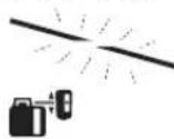
OpTa CbIbKbI bI3JeYe HINBEnPnEydi eckepTy KepcTeKiWi 37 XbIbNbIKTaIbI.
Centre-Line pexnki kepcetkiu 42 y3ikci3 kaHaDb.
IaepcayneciKa6binyepicihne26 TcKeHpeOpTa cB3bK Ta6bHaHa 6bItbpnyd6bcbi7bfaDb.
Potaunbik6acapeketkacaiTbHkbIaMdbknaepe Cayneci KabindayepiciNe 26 TyckeHe aKbipbHaanabbl. Opta cb3bIKbTanKaHHaHc OH oJwe Kypalb Centre-Line pexmi ABOMATBtEipei PeTtenre hic caktanbl nncnne de Kcpctinei.

-13eYKe3iHe Centre-Line pexHmIH ToKtaty yuih Centre-Line pexHmIH nepheciH 19 6acbHb3.
Hemece

-18MeH20eHc nepHepeipA bTOMaTTb HbEnIpNeydi 6eNceHdpy yuH bipre 6acbl3.

Auto

Ja3epKa6bInaybIbIHOpTa cbIbIFbIH Ta6ydbj XblnDaMnDatY
Na3epKa6blaybHbHbOpTa cblbH i3eY potaunllbK
6actbH Xorapbfa KblkybmeH bactana. Erep na3ep
Cayneci opta cb3bK acTbHa Tpyca XHe na3ep
Ka6blaybHbHbH Ka6blnyepicinde60nMa,na3ep
Caynecih KblkybH aHaHbIpy MykIn.

Centre-Line pexmiHnepheciH 19 1aM.2 cek bacbH3.
PotaunBbik 6aTbH ABTomatbl anFa-apTKa Kblxbyb 6actanaBl.
-20 eHic nephecih 6acbHb3.
PotaunabikbacTeMeHReKbIbItbIaBbl.

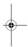


Kaakaika|393
Anti-Drift kyyneci (ADS)
Onwey KpyaibHda Anti-Drift xyyneci 6ap 60bn, on y3akTBk E3repynepiHde Hemece enwey Kpyaib TepbenynepinHe Hemece tabah dipineynepiHde e3repren 6nikTikke HnBeNpnydInKhe OcbmEh 6nIKTK katenirih andbH anaabl.

Im. 30 cek eonwey kpaanbH KockaHHaH coH AntiDrift kyeeci bencenepinedi.
BencnDipyKe3iHne WOK eckepy KepcTeKiwi 38 KaJkbInbIbIKaIbI. BencnDipyEn COKepcTeKiW ydiKciKaHaDi.
Erep enwey KypalbHbH BEpTKaIaNb Kyi e3epce Hemece KaTb KaBbIbIc TipKeNc, OHda Anti-Drift kyynecicke KocblnabI: na3epDIn potaunncbToKtaTbbln WOK eckpty KepcTeKiuli 38XbIbNbKTaNdb. KocblMa5 cekynkna3ep KabblndaybUbHda bblpnydblb6cbuflfaDb.

- Icke KocbIraH Anti-Drift KjyHeciHde Kocy-eipy nepHecin 17 KbIcKa 6acbHb3. ABTomAtb HnBEnHpNe 6actanaIb (Kymblc Kezihderi abTomAtb HnBEnHpNe 392 bTeIHde KaapHb3).
-JaepcayncinH6nKtirH HeririHyKeTe TeKcepin Kepek 6onca enwey KypanbHbH6nKtirH DpybCTah3.
Anti-Drift xyyecin opsi
Anti-Driftxynecin enwey kypanbHbH xymbc ictey ke3iHde eipy mykinh.

-Kocy-ewipy nepheci 17 bacbH3. Anti-Drift xeyne ci eipinreH. wok ckyeptyi 38 nepheci backa Kepcetimmei.
Papametpeuyde caKanmaDb. EJwey KpyanbEpaabIM 6encndi Anti-Drift kYneCimeH icke KocbnabI.
Cb13bIKTBK Kymbc (Line Control) BepTKanDbipexHMde (GRL 500 HV)
OJnwey KpyaIbHbH BepTnKaIbIpeKmInhe poTaun
JeHreinXkai TeHectipy HEmec npaIeIbdi 6aftay yuH
Xoci 6oBihwa opHaactbpyfa 6oana.

-Potaunnkbkka3bkbTbkcafTtinimeh6pyay ywih 18 eHic nepheci, an carat tinihe Kapcbi 6pyay ywih 20 eHic nepheci bacbi3.

OphanaTbipy ± 8,5% aMafbHdaMymkH6oanbl. PotaunBbKbacpeketXacaTbH XbIaMdbKKa 6actanbl y3ikc3 Ketepinei
Centre-Line pexkmi cb3bIKTBK Xymbicta (Line Control) (Ecypertin kapaHb3)
Centre-Line pekmininde enuwey kypanbI aBToMaTbI potaunnblk bactblconfa/ohFa kblnkbTbn naep kaibnaybiuhih opta cb3bfH Tabyra Tpbica.

-Centre-LinepeKmHin nepHeci19wam.2cek 6acbHb3. PoataaIbIK bactbH ABTOMaTTb COHa/ehFa kblKybl bactanaIbI.
Iaey aici:
- Potaunnaik bac tipeirehne oHa Kaibipnabla.
- Naazep cayneci kocbila.
3.Potaunayibk bac confa KaHbIpbilaDb.
4a. Na3ep cayneci ka6b1nay epiciHne 26 Tycin opta cb3bKtbl Ta6abbl.
Hemece
4b. Na3ep cayneci KaBbPbIy aMnBaHbIH COBHaJeHH Ka6bnay epicih Ta6a anMaIb; KaTeiK KObl KepcTeiNei ("AkaynbKTapdbkoio" 399 6etHe kapaHb3).
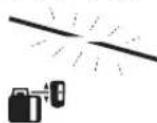
OpTa cb3bKbI 3JeYNe HNBEnpNeydi eckepTy KepcTeKlWi 37 XblbblkTaNbl.
Centre-Line pexmik Kepctkiwi 42 y3dkci3 xahanbl.
IaepcayneciKa6binyepicihne26 TcKeHpeOpTa cB3bK Ta6bHaHa 6bItbpnyd6bcbi7bfaDb.
Potaunbik6acapeketkacaibHkbldamblknaep cayncic kabinyday epicihe 26 tyckehde akbpihdanaibl. Opta cb3bktbTaNkAHHaC OH oIwey Kypanbl Centre-Line pexmni ABOMaTbI eippei.

-13eYKezIHDe Centre-Line pexHmIH ToKtary yuH Centre-Line pexHmIHnepHeciH 19 6acbHb3.
Hemece
-18MeH20eHcIepHenePiABToMaTTb HBeHnPneydi6encdipy yuih 6ipre 6acbHb3.


Ja3epKa6bInaybIbIHOpTa cbl3bIFbIH Ta6ydbI KblnDaMnAty
Ja3epKa6bldaybHbHOpTa cblbH i3epy potaunlkb
6actbH OHfA KbljxMyBmEh 6actanaB. Erep Ja3ep cayneci
opTa cblbkCOn KaftbHaTpycaKHe Ja3ep
Ka6bldaybHbHn Ka6blayepicinde60nmaca,na3ep
cayncih KblxybH aHaHbIpy MykH.

-Centre-Line pexmiin nepheciin 19 wam.2 cek 6acbHb3.
Potaunb6acABTOMaTbOHFa Xblnblna
-20eHic nephecih 6acbHb3.
Potaunbik6acTeMeHReKbInkbItbnala.


394|Ka3a3k1la
Canbictbpmanbi6niktik Kepcetkiu (F cypetin kapaib3)
PoataaIbIKKa3bIKTBiKneHOpTaCb3bIK apalbIbI DnCInNeIe abCOJIOT MaH ([MM] Hemece [IOm]) petIHne Kepcetinei. Kahe "BipnikTepeKpcetKiuiH petTey" 3986tIHKeapaHbIa.
Ja3epKa6bInaybIbIMeHxMbicictey
Cbipta khe iki aimKaTya3ak KaBkTbiktapda enueyne naep caynciH taby ywiH naep Kabnndaybiubn naDanaHbIb3.
-Ⅱa3epKa6bIaaybIbHna3epcayneci Ka6bIaayepicine 26XetTeIH etin opHaTbHbI3.
Onuwey Kypanbl MeH KaBbIKbIKTaN 6aKapy Kypanbl/na3ep Ka6bIaaybIbI apacbHaFbl paHOBaHaNblic
Ketkiy KyinHe naep Ka6blnybIaLR 50 cbMcb3
6aIIaHbc apkblnEiWey KypalbHbN KaBbIKTaH 6ackapy
Kypanbi peIHne Kb3Met etedi.

-PaHnObaNaHbIc KepcTeKlui 33 KepcTeinnaeP Ka6bIaNayBbIbHbN Ka6bIKbTKaTb6ackpy KypanblfHKnucbH6nreNi.
Onuey KypaBbHa 6ipHeue Naep Ka6bIaybItapbH LR 50 peTey MyMKiH.
-0JIwey KpyaIbI MeH na3ep Ka6blndaybIbH eWipiH3.
-KocbIMHa naepKa6blnaybIbH3apTay/caKtayCTAHUNCBiHa 6 canBbI3.

-Paio6aIahbIc KepceTkiu3 33 KepcTeinin naeep KaBInDaybiHbHkAubkTBkTAh 6ackapyKpaIbIphiHKmraCbH6nreinei.
-Ja3epKa6bIaayBbH KaIa TaapTay/caTay cTaHcRbHaH aBn KoBbHla.CocBH KJIeey Kypalh Kocy yin 30 mH iHne Kcy-eipy nepheci17 6acy Kepek.
Eckeptne:Erep6ip enwey KypanbHa 6iphe neaep KaibnaybiuTapbi 6aNaHbCTbIpyFaH 6oNca,Onda COHfpeTTren naep Kaibnaybiu bKaawbIKbIKhan BACkapy KypanbpetHeKb3MeTeDi.Backa naep KaibnaybiuTapbi TeK naep KaibnaybiuTapbi 6oNabi. OIwey dAndiir MeH aBn Dblb6bcH ap naep KaibnaybiuHna XeKe peTpeTey Mymkh. Erep naep Kaibnaybiu bKaawbIKbIKhan BACkapy fynkunncbmenbipre eUce enwey KypanbIeJei.Kocimua naep KaibnaybiuTapbi 6neKe eWiypekek.

ErepaaHbnaHbcy3ince,da6bn db6bcHa KocbIMpaHbnaHbcKepcTeKiui 33 XblnbTaNdb.
Ocbnai eckepTy KepcTeKlWTepi (Mblicbl, yPbIK, Anti-Drift, kAn6pney) Kepcerimeyi Xane enuey Kypalbl KaBkTBkTah BackapbnMaTbHb6enrineHedi.
Eckptne: Ouiuy KypaibHbH, demaibc pexnmi TeK deMaibc pexnmi nepheci 21 KaBbIKtbIKTah 6ackapy fynKunncb6ap naep Ka6bInaybIbHa 6acbl Kocbl KHe eipy Mykhi.
Ja6bn bIb6bcj/kaTbInbIfbn petTey
Ja3ep cayncinH kabbnay epiciHderi 26 ophanacyb cnHaanblk dbbic apknblbenrinehyi MmKIn.
Eki db6bc KaTbIbIbIH TaHday MyMKiH Hemece da6bIbI bIeipy MyMKiH.
Ketki3ykyinHne ctaHapTnnapaMeTp [kaibtbda6bblb6bcbl]

-da6bn d1b6bc/kaTbnBfBn nephecin 24 KepeKTI npametp KcTeIReHwe 6aca 6epiH3. KepceTkiw kO: da6bn d1b6bcb 8WIK

Kanbintbda6bndb6bcB
KaTbIa6blnbl6bcbl
Даын дыбыс/kaTын bIFи napaMeTp i eшуde caKТалmaйд.
Opta cIbIbIK KepcTeKlWiinH napaMeTpIn TaHday
JaepcayncinH ophanacybKa6biny apicinpe"optaa petiHne Kepcy dndirH genrine MyMKH:
KTeKi3y KyiHnDi er cTaHapTbI npaMeTp [Olnwey dAndiir "opta7a/3 MM".

-0nuey dnnirin petrey nepheci 23 kepeki npametp xetirene6aca 6epihi3.
Mbcan DnncnneJe "dan"/"opTaua"/"dpekei" enuwey dndirihh bacbui MeH dan Kepceinei.
Tnwey dndirinH npametpi euyde caKtaMaHdbI.
Barbit KepcetkiuTrepi
Jaep cayncinH kabnay epicHeri 26 opHanacyb Kepcetinei:
15 naep ka6bIaybiuHbH anFbMeH apKa XaBHna"Naep caynei opta cb3bKbTHKOFapbcIHDA" 39 6abfKepcTeKiimeH, "Naep caynci opta cb3bKtAH TIMeH40 6afBn KepcTeKiimeH HeMece opta cb3bK KepcTeKiimeH 43,
onunnybikdaabnbdbibcbiapkblbl.
Ja3epKa6binybIbIbIMTeMeH:ErepJa3epcayneci Ka6binyepicinH26XKofapfblKapTbcIHAnETce,OHda
"Ja3ep cayneci opa cb3bIKbTH KOFapbcBHa" 39 6afbl KepcTeKlJi KaHbI cAlbCTbIPMaJIb 6NIKTIK KepcTeKlJH 32 NIOC MAnI Ja3ep Ka6bIaNbYbIb KaHwAFA KOFapbIfa KTepeiny H KepcTeI.
CnHn Dblblicb Kocybl bOJca CnHn XaTakTa Dblblic 1bIfapabbl.
- Naep Ka6binyabHbH Kepctki 6aftbHda Kofapbl XbNkbTbHb3. Opta benrire 16XakbHayda 6aftb KepcetkiuHIN39 TKy bKepinei.

Kaazakua|395
Ja3epKa6binybiBtBIMXofapbl:Erepna3epcayneci Ka6binyepicihin26TeMHriJxapTbcHAnECE,OHda
"Jaep Cayneci opa cbbiktah TMeH"40 6afbl KepceTkii KaHbIc aIbcIcbIpbMaIbI bIeKtIK KepceTkiHIN3 MHHy CMei Jaep KabJnaybiKaHwaFa TMeHre TcyH KepceTei. CnHAn Db6bcBcIb Kocynb6oCa nHAn XbIaM TaKTTa db6bc WbIFapadbl.
-Ⅱaep ka6binyabibih KepcTeKi 6afbltbHaTMeH Xblkbblb3. Opta 6enrre 16XakbHdayda 6afbl KepcTeKlwiinH 40 TEK yu bki KeipHei.
Ja3ep Ka6binyabuOpTapa:Ja3ep caynci Ka6binyay epiciH 26 opta beniricin16 nkiTirine tce,Onda opta cb3b4 43 KepcTeKiWi JkaHabi.CnHan Kocynb6oNca y3ak yaKbTTbl bIb6ic wanabl.
Erep enwey KypalbXblnKbifraHa naaep Cayneci Kabbnay epiciH 26 KaIaBbIFaBH bOla,coHbf KcpetireH 6aft Bkpcetkiu 39 Hemece 40 WAM.5 ckyH XblnbKtaTbIb.
Strobe-ShieldTM kopfay fyHKnncbI
Ja3epKa6bIaNyblbIcTPOB60KoNTbIKXapblkAp yHIN 3NeKToPONbIK cy3rInep 6ap. Cy3ri, Mbcanbl, KpyblnC MaHHaNapblHcEKepty WAMapbl apKbIbI naDana 6OaTbIH aKayblKTapdH KopFaHbl.
Benriney
OpTaBik6BenriciHne16naepKa6bIaaybIbHohKHe con KaBHa naep CaynecinH 6nktirH 6enriny MmKIn,erep on Ka6bIaay epiciH 26 opTacbHa HetTin 60ncA.
OJwey Kpansb6enrinye dAn TIK (KoNdeHei naep CayncinHe) Hemece KOndeHn (TK Naep CayncinHe) 6afttanybHKamTaMaCb3 etH3, eTnece bengnep naep CayncineH Kblkbn KaalabI.
Дисплей Карыfibl
Ketki3y KyHnIerI cTaNapTTb npaMetp [Dncnnne Japbbf6bcceHd].
JAM. 30 cekyHd eW6ip nephe 6acbImaHaHHcHdcnne Japblfbiwei.
Ke3 KeIeRn nepHeni bacbl Hemece naep cayneci Kabblnday epicihe Tycce, nCIIeN JapbIfk KaTt Kocblndbl.

-Диспнгжарыгншigipyyu nepheci17MeHda6blnbl6bcyl/KaTbIbIbI24 nephecih6acblH3.

Диспелей карын,在аMuTe pye caKaTaNab.
PeKanap yCtaFbIbIMen 6ekity (G cypTeH kapaHb3)
Ja3epKa6bldaybHpeKanapYcTaBbHbH5 Kemerim H Kybpblnc na3epiH enuwey peKaapanpaHda 55 (ka6blkTAP) Hemece eHI 65 MM Dein 6onfA 6acka KEmek KpaIapda 6ekity MykIn.
KbIbXbIpypaacBn586eITkiu6ypaHdaIapMeH56 peKaIa npycTaBbUbHa 536eKtirH3.
-BeKtiKi 6pyaHdaHb546ocatbnpeKaanap YcTaBblH, MbicAlb, KpyblbcnaepiHIn enuwey peKaanapbHa 55 XblNkblTbn,6eKtki 6pyaHdaHb54 KaT TaTbpN KOblHb3.
Batepna57 Kemerimeh peKanap yTafblbH 53 KeJeHe6aftTaHbI.
KncbIK KOblnFAH KIwey KypaIbI Dpypbc EmeC OJIeMepre anbl Keneji.
-Ja3ep Ka6bIaaybIbH KbIbIbIpy paMaCbHa 58 XblkbTbIHbI3.
Onwey KypanbHbH dAnirin TeKcepy
TeMeHdei KymbIcTapeKkaKcbOkbItbIFaHaKeHeMaMaHdbI aadamapapkblnbopbHdanybIkepe.OnueyKpaJIbIHn dndirH TeKcepye Hemece KaHbpnye 3aHbIbIKTap TaHbc60nybKepe.
Danikke ocepe terin karaianap
Kopway TemnepaTpaCbI eKywi acep eteI. EdeHdE Kofapbifa 6oIrah TemnepaTy a3repictepi na3ep cayneciH aybTKybMyMkH.
CbPTbI acepnpenHbI acnantbIK acepnpEe (MbicanB KaftbIbc Hemece KaTbI cokkbnap) aytkynapfa anbln Kenyi MYMKIH. CoI ywiH ap JyMbICTaH andbH KAnhbpneHyin TeKcepHJ3.
AybKynap wam. 20 M KaawbKtbKaTah 6actan MaHb3db
6oyn100 M KaawbKtbKaT a 20 M aybTKyaH eki eedeH Tept
ecere wein ynken 6onyb MykIn.
EeH XaFbHbHa Temnepatypa e3repictepi KaTb60nFaHb yuH Huyey KpyanBn 20 M KaWbKbTkBtAn 6actan WtATNBke opHaty Kepek. OJUey KpyanBn MyMKiHNiIK 6oBHua KMyBc aMfBHyBn,OpTacbHa KObHb3.
Erep enuwe KypanbI TMeHderi CnataTaNFAH enuwe aictepiin H bipinde MaKcMaNdb aybTKyDAn eTIN KeTce, KaNbPneYDi opBHaNbI3 ("Onuwe KypanbIH KaNb6pNeY 396betInHe KapaHbI) HeMece enuwe KypanbIH Bosch cepBnCTIK Kb3Met optaBIfbHaTeKcepIn3.
Hbennpney dndirin ropn3oHTanbl Kynde Tekcepy
Tekcepy yuH typaKbI Ta6aHbI Ka6bIpFaan 30 M 6oc KaBbIKbIK KepeK. X-MeY-OCbTapbHa eNlwey aDiciH opbHday KepeK.
-0nuey KpyanbH ronp3oHTanb Kyiye Ka6bipraaH 30 M KaBbIKbIFbHa dTaTHBe, He KaTb Teric Ta6aHa cy-BtBbI3.0nuey KpyanbH KocbHbI3.
HnBennpnyiaarKaTaHaHHaCOnHa3epcayneciH opTacbHKa6bpFada(THyKTeCi)BenrineJ3.
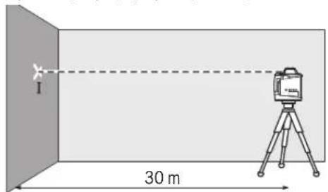
3961Ka3aKaJua
-0nwey KpyanbH 1806bypan, HNBenipneH3 da apfbkabbpfaa naep caynecihn optanbfH (II HkyTeci)6enrinei. II HkyTeciH MymkiHirihue I HkyTeciHycTIHe HeMece actbHa nepneHKnypnepcb3biktatypbHa Ke3 KeTkiH3.
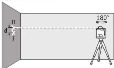
KabpradaefkiEbnireHReHMeHnHyKeTepiHd apalbfEnwey KpaanbHbH enWeHreOcb yuih 6nKiTtHn HAcBtayBkyBn 6inipedi.
Onwey aicih 6aca ocb yuih kaiTanaHb3. On yuih enuwey aciH e anbH enuwey KypaBnH 90° 6paHb3.
30 m enwey KaBbIKbIFbIHda pyKcat etinreH MaKcHMaIdbik ayitky:
30MX±0,1MM/M=±3,0MM.
1 MeH I HkyTepei apacbHaDaBd aaiipMaWbIbIK eKe enwey aicTepehih bipinde MaKcMaIbn6 MM 60nyKepek.
Hbennpney dndirin BeptnkandbI Kynde TeKcepy (GRL 500 HV)
Tekcepy yuih TpyakTbI TaabHbIK Ka6bIPfAaH 10 M 6oc KaawblkTBKepeK Ka6bIPfAa TikTeiyu 6aydb6ekitih3.
-0nwey KpaBbH BepTnKaIbbl KyIe 1tTaNBke HEmec KaTbI Teric Ta6aHaOpHaTbHb3.0nwey KpaBbH Kocbl HBeInpNeH3.
-Onuey KypaBnH Naep caynei TIKteiyih 6aybHIn XofapFby YyBHBnD anopTacbHa TYcetIH erIN 6aftTaHb3. Naep cayneci MeH TIKteyih 6aybHd apanbFb6aybH TeMeHri yuBHa enuwe KypaBnHnTik Cbl3bKTAh ayltKyBH KepeTei.
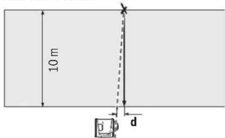
Bnktiri 10 m enwey kawbiktbfbHda pyKcat etinreMaKcImaIblayItky:
10Mx±0,1MM/M=±1MM.
Con yuHd aHbIPMaBbIbIbIe hK6bIme H 1 MM 6oynbKepeK.
OuwekykypaibnKaH6pney
TeMeHei JxMbIcTapeKKaKcbOkbITbIFaH XeHaMaHaHbI aadamap apkblnOpbHdanyIkepe.Onwey KpaJIbIHn dAnirin TeKcepyde HeMece KaHbPnye 3aHbIbIKTap TaHbc6onyIkepe.
Onweky KpansbH Kanibpeydi oTe anOpbHaBb3 Hemece onwey KpyanbH Bosch cepbntk kbImet Kepcety optabfbina Tekepiiz. dAn emec Kaib6pny Dypbc emec onwey hatakepeine anbin Kenedi.
Kann6pneyi TeK eNwey KypaBnH KAn6pney KepeK 6onFaHa fAha icke KocbH3. ONeWey KypaBbl KaNN6pney peKIMInHe 6onFaHa, KaIN6pneydi dIe peTc coBHa DeHH opbHday KepeK, OHda eNwey HtNKeJIePI kate 6onMaHbI.
Eckptne: KaHbpeyEn coH kaHbpeyDi teKcepy KepcTeKiUtepi KaHbpey eceptyi yuiH ceBen KaTaNaiDa 6oIraHa KaTtKepcetinei.
Kan6pny yuHIn TypaKtB Ta6aHbIK TIK Ka6bipFaadn KEMIHDe 30M6ocKaawbIKKepeK.
BapnbokcbterpiKaIin6pneH3 (GRL 500 H: X MeH Y oci; GRL 500 HV: X, Y xane Z oci).
Xocin kannibpney
-0nuey KpyanbH ropn3oHTaIbkyu de uTbte 63 (ka6dbkTap) opHaTBH3.
-ItaTnBt Ka6bipr4aH30Ma7bIKTBfHJaOpHaTbHb3. BAtbPMA XocbTK KepceKtiu Eunwe KypanbHa Ka6bipraFa TIK Kepecyi Kepek.
-0nwey KypaibH KOcbHb3

Kanibpney nepheci 25 men enic nepheci18 wam.2 cek 6ipdien 6acbHb3.

Xocin kainbpey bennici nncnnekepcetinei.

ABTomatbHNBennpnyKe3iHne HNBennpnydi eckepTy KepcTeKiu37 XblbIbKTAidbl.
-0nuey KypanbI HNBennpHreHne KyTe TpybIbIa.
Ja3epKa6bIyabIbKemerImeHoptaCb3bIKtI Tab6Bn opta Cb3bIKTB"X1"6NikTirH Ka6bIpafaEiK3iHj3.
-0nwey Kypanb1n 180°6ypan WtTnB 6nKtiriH eareptnehi3.
-HNBennpneydi eckepty KepcTeKiWi 37 XblnbIbKtaydbi TOKtan enwey Kypanbl HNBennpneHreHe KYE TpybHbIa.
-Ja3epKa6bIaaybIuBKeMErImeH opta cIbIbKbI Ta6bIn opta cIbIbKbIH "X2"XaHa 6nKiTirH Ka6bIpara etkizhi3.
“X1"MeH“X2"opTaCb3bKTabpHbH,AnOpTacBH Tabbin OHa naep KabbnaybHOpTaBenrIme 16 opHaNaCTbPbHb3.


Kaakua|397


-18 Hemece 20 enic nepheci n opta cb3bik Kepcetkii4 43 ydiikci3 xHaHsa 6acbl. CnHan Kocnyb6oIca yakbltb db6bc wanaDb.
KaHbpey nepheci 25 KaHbpeyei caTay yuih 6acbiH3.


KanBpNey aarTanybHbN 6enrici nncnneKeepctinei.
Kannbpeydi aiktaehn coH kane annbpey Mymkiinirin anbin Tactay wih HBNepny dndirin Tekcepy Kepek 6oana (HNBepny dndirin ropnoTanbl Kyinde Tekepy,395 btiHe KapaH3). AbyiKy ± 3 ,0 MM ani de pyKcat etireh makcmaanbl iektepihen tbc ta: eIwey kpaBn Bosch cepBnctik Kb3MET Kepcy optabibfHda TekeptipiH3.
Yocinkanh6pney
-0nuey KpyaBnH ropn3oHTanbl Kynde WtAnBte 63 (ka6dbkTap) opHaTBHb3.
-ItatnBt Ka6bipFaHaH 30 M Ka7bIKTbIFbIHda opHaTbIHbI3. BAtbIpMa YocbTik KepcTeKiUeIwey KypaIbIHda Ka6bIPfAfa TIK Kepcetyi KepeK.
-0nuey KypaBbH KocbHbIa.


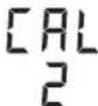
Kanibpney nepheci 25 men enic nephecin 20 am. 2 cek 6ipen 6acbHb3.
Yocinkanh6pney6enrici dncnnneKepcetinei.
ABTombbl HBNBnnpney Ke3iHne HNBennpnyi eckepTy KepcetKiui 37 XblbblkTaIbl.
-0uwey KpaBb HnBennpneHReHwe Kyte TypbHbI3.
-ⅡaepKa6binyabuKemerimeHoptaCb3bKbTa6bIn opta cbl3bKtBnY1"6niktirnKa6biparaetki3iH3.
-0nuey kypalb1 180°6ypan uTatNB 6niktiriH e3reptnehi.
-HNBennpneydi eckepty Kepctkiwi 37 Xbblbltaydbi TOkTAn OJwey KpaIbI HNBennpneHReHHe KYTe TpybHbIa.
-Ⅱaep Kabinaybblkemimerh opta cb3iktb tabbin opta cb3iktbH“Y2”kaha6nkiTirih kaibparaetKiaiHa.
“Y1"MeH“Y2"opTa cIbIbKTapbIHnDnOpTacbIH Ta6bn OHa na3ep Ka6blnDaBbHnOpTa 6enrimeH 16 opHaanactbipbHb3.


-18 Hemece 20 eHic nepheciH opta cb3bIK Kepcetkii4 4y3diKci3 jHaHaI6acblH3.CnHAn Kocynb6onca yakbltbblb6bcwana.
- KaHbpey nepheci 25 kaHbpeyei caKtay yuH 6acbHb3.

Kannbpny aaryantaybHbHb6ntrici nncneide kepcetinei.
Kann6pnyi anKaTafHnH coK kane KAn6pney MymkiHirin anbIn Tactay ywH HBeHnpEy dndirin TeKcepy Kepek 6oIaBti ("HBeHnpEy dndirin ropnoHTaIbkyne TeKcepy"395 6etIHe kapaHb3). Aytky ± 3,0 MM anIe pyKcat erInreH MaKcMaIbnI bIeKteipHen TbIC kAtca: eNwey KypanbH Bosch cepBnCTIK Kb3MET KepCey optabfbHaTeKcepTipiH3.
Zocin kann6pney (GRL 500 HV)
-TikTeiyi6ayKemerimehKa6bIpraJaTik Cbl3bIKtBcbl3bHb3.
-0nWey KypaBbH BepTnKaanDb Kynde WtTaTHBe 63 (ka6dbkTap) opHaTBHb3.
- LITaHTBtI Ka6bipFaJah 5-10 M KaUbIKTbIFbIHdaOpHaTBHb3.
-0nuey KypanbH KocbHbI3.

-Kanib6pney nepheci 25 men enic nepheciin 18 wam. 2 cek 6ipdei bacbHb3.


Xocin kainbpey bencrici nncnnekepcetinei.
-ItaTnBti naep cayneci kabipraafabfikcibkTaH KeJeHeH eTeiH etin 6afttaH3.
ABTombHNBenpneyKe3iHne HNBennpnyi eckepTy KepcetKiui 37 KbblbblkTaHbl.
-0nuey KypanbHNBennpHeHReKyTe TpybHb3.

18 HeMece 20 hic nepHecin naep Cayneci Kabiprafaftikcb3biknnapannenbdi tKeHwE bacbHbI3.
-ErepKantay6oMaca anbHbI KadaamapdbKaTalaHb3 (WtATNBti TeHecTipy, eNwey KypaBn HnBeHnpney, naep cayneicn enic nephepei Kemerimn 6faTTay).

-Kann6pney nepheci 25 kann6pnydi caTay ywiin bacbiH3.

Kannbpny aaykTanybHbHb6benrici nncnne de Kepcetinei.
Kan6pnyi anKaTafHahn coKe Kan6pney MymkiHirin anbin Tactay ywih HbEnnpny dAnirin Tekcepy Kepek 6oana (HbEnnpny dAnirin Beptnkanbl Kynde Tekcep'.396 betIne KapaHb3). Aytky ± 1 MM ani de pyKcat etinreH mKcHmAnbl Weekteriphen blic Xatca: eIwey KypanbH Bosch cepBntik Kb3MET Kepcety optabibfbHa TeKcepTipiH3.


398|Ka3a3k11a
Паданану hyckaynapbI
Onwey KypanbpaNo yuBbIFbIMe Hka6DbIKtanFaH. XeprinikTI naiDanaHy WeKeTeyNepiH, MbicaobiywaKapda HeMece emxahanapda, caKtay KepeK.
Benriney yin HapaihIM TeK Ia3ep Cb13bIFbHbH optanbfHnabHbI3. Na3ep Cb13bFbHbH eHI KaBbIKbKNeH 03repei
BipnikTeKepcetKiinpeTey
PotaunabikKa3bIKbIKHehOpTa cb3bIK apaibfIbIHCnneJe ([MM]HemeC [IOHM:OH6NIKTH 6pi/6nweKTepe]) petihe Kepcetinei.
Ketki3y KyiHde cTaNapTbI npaMeTp [MM].

-0nneyndirinpeTey nepheci 23KHe 20 enic nepheci Kepekti npaMeTp KcTeIReHwe 6aca6epiH3.

BipniikTeprinnapaMepti eWyde caKaTaNab.
Ia3ep Kepy Ke3indipiri (KepeK-kaapakTap)
Iaep Kepy Ke3inDipiri Kopway Japbfbh cy3rineNi. On apKblnlaepdi Hkb3bn Japbfbk Ke3 yuiH JApKbHbpaK 60ana.
P3epKepyKe3inipirihKoprahbiuKe3inipiri peHne naanana6aHbI. P3ep Kepy Ke3inipiri naep caynecihKaKcbpaKepyYuiH Kbi3MeJxacaiDb, bipakon na3ep caynciHeH KopfamaiDbI.
PaeKepyKe3inDipirin Kyn Ke3inDipiri peHne Hemece kon Ko3ranbcihna naananaa6ha3. PaeKepi Ke3inDipiri ynbTpaHnolet caynepeH tonbIK Koprampeh KepyKaunetih aaztabl.
Tafahmeh naindanahy (kepek-xkapaKTap)
Onwey KypalbHda WtATNBte TIK naDanaHy win 5/8" WtATNB natPOh b6ap. Onwey KypaBn HwTATNB natPOhMeH WtATNBtIN 5/8" 6paHacbHa cAlbn WtATNBtIN 6ekTIiW 6paHacbImeH 6ekITIi3.
UbifapbyiHa dn EJWem uKanacb6ap tTnBneH 636nIKTK e3epyihtkenepeTeyMmkiH.
Ka6bipranbik yctafbiu nen bypanay acna6bimeh xymbic ictey (kepek-xapakTap)
Onwey KpaBn HKe He Ka6bipFaBn YcTaFbIuT Typanay
acna6bIme 59 opHaty MmKIn. On yuiH Ka6bipFaBn
YcTaFbIuTbH 5/8" bpaHdAcBn 62 eWey KpaBnHaBfB
WATTN NaTPOhHa 6ypan 6ekitih3.
Ka6bipfada opHaty: Ka6bipfada opHaty w7atNB W7bFtBn 6bnKTIiHEn XoFapbda HemeCe TpyakTbe EmeC TabaHaJa XaHe 8taTNCi3XyMbic IcTeye YcbHbIaNab. On ywn Ka6bipfAblk YCTaFbWtB5 59 opHbTaNFaH enwey KypalbEme Ka6bipfada MymkiuNik BoBHnHa KeIeHene pette Bekitih3.
Ka6bipFada 6ekity ywih Kab6bpFalbIKyCTaFbIHTbl 59 6ekitkiu 6pyaHdameH 60 eHI MAKCMHdJI 8 MM 6oNfah peKada 6ekity MyMKH Hemece eKI INRIUKE acy MyMKH.
TATNBTE OPHATy: Ka6biprafbnik YcTaftbl 59XHe WtATNB natoPBOHnHaWtATNBTHApTKbI XaFBHda 6ypan 6eKity MyMkiH. MyHdai 6eKity apHahbi peTte potaunBkXa3bIKTBk Heri3ri cb3bKa 6aftTnFaH Ke3de YcbHbnaBbl
Typanay acnabimen opnatbnfah onlwey kpaanbH TIK (kabipraada opnatya) hemec e KeIeHEN (WtataNBte opnatya) wam. 16 cmaMaKaTka KblkbTy MymKIn. On yuH typanay acnabHda 61 bpaHacBn Bocatbn enlwey KpaanbHKepekti Kyre KblkbItbHb3 da 61 bpaHacBn KaTb 6ypan 6ekitih3.
OuwepeKacbHnnaDanaHy (KepeK-kaPakTap) (H cypTeH KapaHb13)
Terictepdi Tekepy Hemece Kynamanapdb6enriney uin enwey peKacbl 55 men naep Ka6bIaaybIbHn nainanahy ycbHbIaBl.
OnwepeKacbHb5 5yctInde caNbcTbpMaBb enwey
Ukanacb(±50cm)benrIneHRe. Hnbldk6nktirnTeMeHe
UbbfcbHa TaHay MyMKiH. Ocblan KepeKti 6nKtIK
aytkynapbH TkeNe Kepy MyMKiH.
TadaHMyMbicanapbi
KypbInbc WYHKbpnapbHbIH TepeHdirin Tekcepy (I cypetin KapaHbi3)
-0nuey KpyaBnH TypaKtBi Ta6aHfKa KObHb3 Hemece 1NTBnke 63 opHaTbHb3.
IHTaTHBHeHxMbicItey:naepcayneHKepeKTI 6nIKTKkeBaftTbHa3.BnIKTKiHbCaHbIKJxepre TaBImaHa3HEmeceTEKcepH3. HTaTHBCi3XMybcICtey:Paepcb3bIfbMeH TaHbH WHyTe apacbHa4b6nIKTKepaibMaUbNbIFbHOnWeH3. ONeuHeRb6nIKTkapablBuHbCahDbKxepre TaBImaHa3HEmeceTEKcepH3.
¥3bHKaBbKbTbKapDbEeWeydeKeepriacepIeKeMeHITy yuHEnwey KypabHepaMbIMxMybICaMaFbHbH optacbHa KObln WtATNbBe opHaTy KepeK.
TpyaktbIeMec TabaHa JyMbic ictereh Ke3e eJnwey KypabHtATTNBKe 63 opHbHb3.KeK KmbiDay Hemece OJWey Kypabbl Kaftiny Ke3iHderi Kate OJWeyNepDIn anDbH any yuiH Anti-Drift fynkunrcb6enCeHdi bonybHa Ke3 keTki3iH3.


Kaazakua|399
Akaaynbiktapdbkoio
Katenik kOtanbap6aakaynbikTap

AkaynbkTBkKATENIK KOblDnCneNeKePcetineJI.
-AkaynbKbIkoIO("UeWim"kapaHb3).

-CocBn Centre-Line peKmI 19 MeH da6bI dIb6bcI/kaTbIbIf24 nephenepin 6ipde 6acBh3.
ErepakaynbicattjxohbIcna, kateiik KOdbHbHKepcetkiMeH abTOMaTbH HBeHnpey icke Kocblanb (HHeHnpny aBOMATKacb3 3916eIHne kapaHb3.
Erepakaybik ani de Typca, eHwe KpaBbH Bosch cepBnctIK KbI3MeT KepeCy optanfbHda TeKceTipy Kepek 6oana.
| Акayльконы Akay Шewimi Керстkiш | |
| 001 Θлшей Краралын X оci e3 Новелорley аимафыншam. 8,5 % (5°) Тбс Тур. | - Θлшей Краралын X оci boиь opнал actырьts. |
| 002 Θлшей Краралын Y оci e3 Новелорley аимафыншam. 8,5 % (5°) Тбс Tур. | - Θлшей Краралын Y оci boиь opнал actырьts. |
| 003 (GRL 500 HV) | Θлшей Краралын Z оci ветникалды разимide e3 Новелорley aimaflan sham. 8,5 % (5°) Тыс Тур. |
| 004 Θлшей Краралы узblдь ecзreprенон сон 8,5 % кeп кисы Тур. | - Θлшей Краралы Кайta opнал actырьts. |
| - 18 Имесе 20 ecic посясin диспение пос mэни 8,5% дан кем керсөнше bacaBPIN3 ("Енст ретvey" 392 betinde karapыts). | |
| 005 АВТOMATБI HИВЕЛРЕУ yzaKыгь otiiДi. Θлшей Краралын HИВЕЛPЕУ MUMKIN emec. | - Θлшей Краралын Туракты tabанга Кочьндз Hemece штатвke bepik opnatbHiz. Koprшay dipindeycis 6olyы kepek. |
| 006 Kepekti ecic bopocbт ecic kumbicnida жетинд. | - Θлшей Краралын Туракты tabanга Кочьндз Hemece штатвke bepik opnatbHiz. Koprшay dipindeycis 6olyы kepek. |
| 007 Лаэрдin рotingaцлыб bacs ai halmai Жатыр. | - Centre-Line pexmni 19 мени дыысы/dыбics Котылыб 24 посясin biderдь bcsы. |
| - Θлшей Краралын чирлдз ("Чиру" 389 betinde karapыts). | |
| - Θлшей Краралы Када Косынд. | |
| 008 Centre-Line pexmniide i3dey kezinda lazer сaynci dianaazdoHybIn cohyda.deiHnlazer kaibdoyu bshbIn kaibdoyai maFbIn Ta6a anmaDы. | - Θлшей Краралы Мен lazer Kaibdoyu bshbIn apacbHdA kepietin bai nahbsc yazirengin Tekcepin pekek bo5ca Плшey Краралын opналactырьts. |
| Ereр кatenik кaita naia da bosca, олшey Краралы Men lazer kaibdoyu bshbIn apacbFb In kbickapab. | |
| 009 Cbyrkbi aceperap arkbll (MbcaIb, kaiblcic hemeecke kaTb cofynap) Centre- Line peximime keedepriz jaxalbIn qatbip. | - Θлшей Краралы Када opналactырьts. |
| Θлшей Краралы Туракты tabanга Кочьндз Hemece штатвke bepik opnatbHiz. Koprшay dipindeycis 6olyы kepek. | |
| - Otra cybisKtby tabу wsin i3dey adiciH kaita bactaBis ("Centre-Line pexmni" 392 betinde карыts). | |
| I3dey kezindne laser caynciHin dlya anazdoHybIn a damdap Hemece backa ontikaLbK keedeprinep apkblbYzilmeyiHe Ke3 ketkizhi3. | |
| Ereр кatenik кaita naia da bosca, олшey Краралы МEN lazer kaibdoyu bshbIn apacbFb In kbickapab. | |


400|Kaazakwa
AkybikkoBj Akay Wewimi Kepcetkiwi
020
KannbikatenikTe
Centre-Line pexmi 19 men da6bI nb6bcI/b6bc KaTbIbIbIb24 nepHeneipin bipde6acbl3.
Thuey KypanbH eWipiH3 ("Uwipy" 389 betIne kapaHbI3).
-ηιωeу KypaBih KaHra KocbHbI3.
033KopwuykabIKbIbI naepKa6blndayibIbIyinTbIMKapbIK.
-Ka6bIydayepiciHIXapbIKTBfBHTomeHdTeiH3.
Katenik KogTapb1cB13 aKaynbikTap
Akay Weiwimi
Kniye KypaIbHemece Naep Ka6blndaybiu Ko6blMaJ KaTbIp.
-Enwey KpyaIbIH TpyakTbI Ta6aHaKoBbHb3 HEmeCE WtATNBke bepik opHaTbHb3. Kopway dipinpeyci3 60nybl Kepek. Erep kalenik kanca, ekineti Bosch cepnctik Kb13MetKepcety optalbfbHa xa6apnaCbHb3.
-0nuey KpyaBnHbH aKkyMnyTOpbH 3apraTahb3 ("AkkymnyTOpbl 3apraTay" 388 betInhe kapaHb3).
-Onuey KypaBn KaTaNocbHb3. ErepKatenikKanca,ekinettBosch cepBnctIKkb3MeKepcety optabfbHa xaabapnaCbHb3.
Ouwey KpaanbMeH/Hemece Naep KaBnayBHBnAkkymaTOpnei 3aprTaMaMbbl.
- Θηωe KypaβI MeH/Hemec Naερ KabIbIaIybiIbI (KaITa) ONTImaIbI 3apIaTay Tempepa aIMaIbHa (0°C ...+40°C) XeTKeHWe KYTe TpybIbI3.
Eneey KpyaBm MeH na3ep Ka6bnaybIbI kocynbl 60nFaHa na3ep Ka6bnaybIbIHbH aKKyMnyTOpbl 3aprCbldAnbl.
-KaannbHkyKeNTipy13TMyMecin6acbHbIa. ΘnweyKpapanbIeJi.
Ja3epKa6blnaybblb6y3bnFaH, KaTkH Hemece KonFaIFaH 60bn yPbKnab6bblb ickeKocblbl.
KannbnyKeTipy13TmyMeCIn6abHbIa. da6blnb6bcmbmHeOnwey KpaBbOwipinei.
naepKa6bInaybiHbHa yaKbTTbK 6aFapnAmabIK aKaynbKnaiDa 6onbl.


- Na3ep Ka6bIyabHJxKTeK3y KyInHe KaTapy yuiH Kcy-eipy nepheci 17 MeH enwey dAnirin peTty nepheci 23 bipnEbnBIs. OJIeuy dAniri (opta), DNcIIeN JkapbIKtBfB (6enceHi), bpiKTEp KpcetKiU (MM) XaHe da6bI nb6bcbl (KaIbITbl) cTaNapDTbI napamTepnePi KaTa peTtenedi.


Kaazakua|401
TexHkAblk KyTIM XeHe Kbi3Met
KbI3MeT KOpCteTy KHe Ta3aay
-Potaunibknaepdi,3apraTay KpaanbH JHe naep Kaabnaybblh Ta3a YcTaHb3.
-Potaunibknaepdi,3apnTay KpaanHxHe naep KaBbIaayblbIH cyHa Hemece backacybiKTbIKTapFa 6aTbpMaHb3.
-JaactahynapdbcyaHafan,ymcakw6epekencypnti3. Kyfbiu 3aattapdbHeMece epitkiuTepni naDalaHa6b13.
-Potaunlkbnaneepne naepinbfbtctecirnderi amaktapbljxmyeni Typde apnaib Ta3anlan TaIbikTapra Ha3ap aydpbHb3.
Tytbinybifa KbI3MeT KepceTy XaHe naJaAnaHy Kehectepi
Kb3MeT KepcTeY we6epxHaCbE hHIMDi KeHDey KeHe KYTy, coHdai-ak KocanBb 6enweKTeP typanb cypaKaTpFa Xayan bepei. KaKeTTi cb36anap MeH KocanBb 6enweKTeP typanb aknapaTbMbHa MeKeHkaJaN tabacb3:
www.bosch-pt.com
KeHec 6epyui Bosch Kbi3MeTkePepi eHimDi naHdAnaHy Xane onapbIH KocanB6eIWeKTePi TpaKaTapbHb3Fa TnHaKaTbXayan 6pepi.
CypaTAP KOI XHE KOCANKb6eWKeTpe TANCbPb6 bepy Ke3Hne MInDETI TYPe 0HIMDn3ayBtTBk TaKTaNacbHdAfb1 10-caHBiE HmHemHemipihKa3bHb3.
Ohdpuyi TanaTapbl MeH HopMaIapbIbHcKaTanyBIme
AeKTP KpyaIbH XKeHDey XKeH KeINJI Kb3MeT KepCey
6apblk MemLekeTep ayMaftbHaTe KpOBept Bow
PhmAblb HMeCe aBOpTHaunHaFb Ka3MeT KepCey
opTaNbKTapbHdaOpbHdaNda.
ECKEPTY!3aHcb3KoJmMeH eKeiHReH eHIMeppi naDanaHy Kayinti, deHcaynbfbHb3Fa 3nH KENTipy MymkiH. OHmeppi 3aHcb3Xacay XHe TaPaty ekimuiK XHe KblmbCTbIK Taptin 60bHwa 3aHMeH KydanaHaBbl.
Ka3aKCTah
TybHybInapraKeHec6epyKaheWarBIMapdbiKa6blnay optaIbIbI:
"PoBept Bow" (Robert Bosch) KUJC
AMMaTbIK
Ka3aKCTaH Pecny6nIkacbl
050012
Mypa76aeB K., 180 y
"Tepemc"50,7ka bat
Ten.: +7 (727) 331 3100
_aKc: + 7(727)2330787
E-Mail: ptka@bosch.com
CepBCTIK Kbi3MET KepeCy optaikTapBi MeH Ka6blIay nyHKTePiHiM MeKeH-KaMbI TypaIbI TOnbIKKaHe 03EKTi aknapaTb Ci3: www.bosch-professional.kz pecmN caTTah ana anacbi3
Tacbimanday
BnyIHTN-HoHbIKaKKyMnTOpnapKayiTIyapnapra KOblaTbIH tananTAPra caBonybKepeK.PaIaNAnHybI aKKyMnTOpnapbl KeWeede KocbIMuKaXaTApcb3 TaBImaIaNanbl.
Yiwihui Tynfnap (Mbicanb, aye Keiiri Hemece Xibepy) opamara XeHe Mapkanaipra KOnbInatbH apHaBtanaTAPdc bCaTay Kepe. Xibepyre DaBHday Ke3Hde Kayinti KyyKTe p MaMaHbHa xabapnacy Kepe.
AkkymyIaTOpbl Kopnycbl 3akbImdaHan 60ncaFana HxibepiHj. Aushk tyinCenepri XenimdeHjXhe AKKMYIaTOpbl opamada Ko3FaMmaTbHdai opahB3
KaKet 60nca, KocbIMua yIITbIK epexepeepdi cakTaHbIa.
Kedere kapaTy

Potaunbik naepdi, 3aparTay kypanbIH, naep Ka6blndaybiuBih, akkymyntop, ka6blkTapbi MeH opamacBH KOpuaFAH optAhb KopfAHTB H KeDEKapatyopbHa TancbipyKaKeT.

Potaunbiknacep3,zaepay KpaBih,naep Ka6blaybwhHxhe AkyMnyTopnpab/ 6atapenapblyKOKbcbHaTactaHa3!
Tek kana EO endepi yuhi:
Eypona 2012/19/EU epexeci bohHna jkapamcb3 enuwey KypanapbI kHe Eypona 2006/66/EC epexeci bohHna 3aKbIMdAHaH HeMece eckkMynTOp/6aTapeennap 6eKek HHaBIn, KaDere XapatblnykKaKeT.
Bipiktipireh akkymyntopnapbI TEK kDere xapaty yinMamahdap apkblbI bIfapyra 6onabI. Kopnyc KaTAmacbiAaBn eOnwey KpaBbH 63y MymkiH.
AkkymyIaTOpbl EeWey KypalbHaH aIbIn KOIO yuH IN AkkymyIaTOp 3apdcb3 6onybKepe. Kopnyctarbl
6pyanlanaPdl 6ypan wifapbn, akkyMnyTOpbl 7bIfapy yuH KOpync KaTnMaCbH anbln KoBhlB3. Kbicka TybIKaYduh Anbln any uWih AkkyMnyTOpdaFb I Kocanpdpipine Hc biH axbpatbn, coHbHaN
nonioctepdi OkuaynaHdbpHbH3. TOnbIK 3apdcb3DaHaFaH
60anca da, AkkymyIaTOpda aKyat KaIbIn, Kbicka Tu bKtanyda
icke KocblNybl MyMKIN.
AkkymynTopnap/6aTapeenap:
JIHTH-NHOHBK:
"TacbImaIay"TapaybHaIbI,401 6beiHderi HcyckaynapblOpbHaNbI3.
TexHnKanbIK 63repictepehriy KykbfbcaKaTanaabI.
402 | Romaná
Româna
Cuprins
Instructiuni privind siguranta si protectia muncii ... 403
Nivelà laser rotativá 403
Incarcator 403
Receptor laser/telecomanda 404
Laser Radiation Class 2 do not stare into beam IEC 60825-1:2014 <1mW,635 nm
Dacā textul placutei de averizare nu este in limba tārii dumneavoastrā, inainte de prima utilizare, lipiṭi deasupra acesteia eticheta autocolantā in limba tārii dumeavoastrā, din setul delivrare.
Nu indreptati raza laser asupra personel sau animalelor si nu priviti nici dumneavoastr direct raza laser sau reflexia acesteia. Prin aceasta ati putea provoca orbirea personel, cauza accidente sauvatama ochii.
Service sculelectric
Strada Horia Macelariu Nr. 30-34, sector 1
013937 Bucuresti
Yka3aHHa 3a ONTHMaHa pa6oTa c akymyNaToPhaTa 6aTeHn 428
Pa6ota c ypeia 428
Iyskahe B eKcnloatauia 428
IocTabaHe Ha H3MepBaTeHnHa ypeB pa6oTHa
no3uHa 428
Pa60Ta C n3MepBaTeHnH ypeI (BnKte fHr.C) 428
PekimnHa pa6ota 428
BknIOUbaHe n3KnIOUbaHe 428
Iyskahe B eckcnloaataa 428
BknouBahe 428
I3KIOUBAHe 429
PexMM FOTOBHOCT 429
ABTomaTHUHO H3KIOUBAHe 429
BaTePn3a YacOBnKa 3a pealno BpeMe (Real Time Clock -RTC) 430
AanapMeHa CnCTema cpeu KpaXba 430
AKNBnPaHe Ha aIapMeHaTa CnCTema cpeu Ky KpaXba. 430
H3noI3BaHe Ha aIapMeHaTa CnCTema CpeuKpaX6a 430
Poka3BaHe npobepka Ha KaIIN6pnpaHTo (IpeDynpdTeHEn HnNkAtOp 3a KaIIN6pnpaHe) .430
H3KJIUOVABe Ha HINDAKATOpHTe 3a npOBepKa Ha KaIN6pnpaHTo .431
IpeopbHTeHn HneCTBna pHn noBaHa
IpeDynpTeHnHTe HnDnKaTOpN 3a IpoBepKa Ha
Kan6papaHeTo .431
PekmmHa pa6ota .431 P03nHa oCte X Y. .431
PotaioHepexnM 431
063op Ha pexHMnTe Ha pa6oTa. 431
ABTOMaTHUHO HnBeHpaHe 431
ABTomatHNO HNBENpaHe CneB KKnOuBaHoTo 431
ABTomauHO HnBEnpaHe No BpeMe Ha pa6ota .431
PezHM Ha KaIOH cnpMO eooc. 431
HactpoKaHa HakNoHa 431
PezHM"cpedHaIHHa"(BnKTeΦnR.D) 432
UckopbaHe Ha npocca Ha HAMpaHe Ha
ueHtpaHaTa nnnna 432
Cncrema Anti-Drift (ADS) 432
H3KIOUbaHe Ha cHcTeMaTa Anti-Drift 432
Линеньеон реким (Line Control) Вертукално (GRL 500 HV) 433
PeknM"cpedHaIHHa"npHnHHeeHpeknnm (Line Control) (BnKTe pnr.E) 433
UckopbaHe Ha npocca Ha HAMpaHe Ha
UeHTpHaHataLinna 433
H3o6pa3BaHa He oTHOCHTenHaTBAHCouHa (BnKTeΦn.F) 433
Pa6ota cna3epen npneMHNK 433
PaIOBpb3ka MeKJy I3MepBaTeHNH ypeI nIcTahUHOHTO ynpAbeHne/na3epHnN npEmHHK..433
HactpoBaHe Ha 3ByKOBnCnHaN/cnTa Ha 3ByKa..434
H36paHe Ha HactpoKaTa 3a HnDnKaTopa
CpeHa nnHna. .434
CHMBONH3a NOCOKaHa OTKNOHeHHeTo 434
3auntha yuknur Strobe ShieldTM 435
Mapknape 435
OcbetneHHe Ha dncnner 435
MOHTHpaHE B CTOIka KbM NaTa 3a H3MepeBaHe (BnKte fngypa G) .435


422|Бьлгарскn
PpOBePKa HtouHocTtHa H3MepBaTeHnHpyeI 435
FaKTOpH, BInReuH Na ToUHocTtA 435
PpOBeRkaHaToHocTtHa HnBHeIpaHe npn XOp3oHTaJIHO NoIOKeHne 435
PpOBePKaHaTOHocTtHa HnBEnIpaHe npi BepTKKaIIHO IIOJKeHHe (GRL 500 HV) 436
KaIbpupeHa n3MepBaTeHNH ypei 436
Kan6pnpaHe Ha ocTa X 436
KanibpnpaHe Ha ocTa Y 437
KanibpnpaHa ocTa Z (GRL 500 HV) 437
yka3aHna 3a pa60ta. 438
HactpoBaHe Ha MepHnte eHNn.. 438
OuHna 3a HabnIpaBaHe Ha Ia3epnHa lyb (DIOBnHnTeHNO pIncNo6bnHe) 438
Pa6oTa CbC CTaTHB (DomblHHTeHnO npncnoc6neHHe) 438
Pa60aC npncnocobneHHeTo 3a3xBaUaHe KbM cTeHa HMOyHa 3a HAcOuBaHe (DOnbHInTeHIO npncnoc6BHe) 438
Pa60Ta C H3MepBaTeHa NeTBA (DOnbHnHTeHo npncIOco6IeHne) (BHXTe FHyppaH) 438
PpHmepn 438
Laser Radiation Class 2 do not stare into beam
IEC60825-1:2014<1mW,635nm
AkoTeKCTbHa npedynpeHntnHaTaTabenKaHe ha BaunraeNK, npdny nckahe Bekcnoataa 3anene Te Bbpxy TaBekkata BKnouehn BOKOMNeKTOBkata CTNKeP cTeKCT Ha BaunnaeNK.

He hacooyaBte na3epnna bkykbmXopa nnBBOHTN BHHMabaTe da He nOrneHete HEnoCpeDcBeHO cpeu na3epnna IbHn Cpey HerOBo OPaxhene. Taka MoKETe Da 3acIeNITE XOPa, Da npHuNHITe TpyOBH 3IOnONyKn Hn Da npEni3BnKaTe yBpExdaHe Ha OHTe.
Ako na3epnHrTbH nonaHBe BOHTe, H3aTBOpTe Bb3MOxHO H-6bp30 HOTpBnHETe rnaBata Ch OT na3epHHb4.
He H3BbPbBaIe H3MeHEnHn No na3epHoTo 06OpyDbaHe.
He h3non3BaTe OUnnata 3a H6nOdaBaHe Ha Na3epHnHa bKaTo npEpa3HH pa60THn OUnHa. Teu ouHa cnYkat 3a No-do6pTo Ha6nOdaBaHe Ha Na3epHnHa, Te He npEpa3BAt OT Hero.
He h3non3BaIte Ounnata 3a H6nOdaBaHae Ha na3epHHa b4u KaTO CbHueBn OounHa nn DOkato yuctBaTe BynHHTO dBXKeHHe. Ounnata 3a H6nOdaBaHae Ha na3epHHa b4u He OcNpyBaBAT 3auNTa OT YtPaBNOETOBITEbHOrpaHuaBb3npHemaHTo Ha cBTobete.
DonyckaiTe H3MepBaTeHnHrT ypeJa 6bJe peMoHTn paH cAmO OT KBAHnHnHnPAH N TeXnHn H cAmO Cn-Non3BaHe HaOpHNHaHnPe3epBnH qactH.CToBa ce rpaHTnpa3ana3BaHeto HaФyHKnHTe,ocnrypBaun6e3- onaChocTtHa H3MepBaTeHnHyrpeJ.
He octabTte Ea 6e3 npK hA3Op da pa6oTc H3MePbATEHnYpe. Morat HeBONHO da 3acnenTdpyTN Xopa.
He pa6oTeTe cH3MepBaTeHNHa ypeD BCpeDa c NobHWeHa ONaCHocT OEKcNIO3HN, B KOaTO HMa NcEChO3aNAHmN TeHOCTH, rA3OBe Hn npaxOBE. B H3MepBaTeHNHa ypeD MoT a Da Bb3HKnHAT NckPn, KOHTa Da Bb3IIaMeHAT npaxa Hn NapHTe.

IpeNa3BaIte H3MePbAteHnHa ypeO tHaPraBaHe, CbIoo HApN. IOTnpObIaXHTeHNO Bb3dEiCTBHe Na PpKa CbHueBa CBeTnHa NOrb, KaKTo N OTHAMOKPRAH NOBIAxHBAHe. CbIeCTByaOnaCHOCT OT EKCIIIO3HA.


BbIrapckn|423
PnHnepaBnHNO H3nON3BaHe OAKymyNaToph6aTe pnaOHT He MoKe Da H3Teue eNeKTPoNt. H36raBaiTe KOHTAKTa C Hero.AKO BbIpeKu ToBA HA KOKATA Bn noJaHHe eNEKTPoNt, H3nPaKHe MeCToTo oBnHc C BoDa.AKO eNEKTPoNt NOnaHE BOnHTe Bn, He3a6BaHc Ce 06bpHeTae 3a NmOoi KbM ouHenekap.ENEKTPoNtBt MOKe Da npEIN3BnKa H3rapaHNA Ho KOKATA.
Pn nobpekdahe H hnpabHnae kcnnoataaonr O akymynatopnata 6atepna Morat da ce otdenr napn. Ipobetpe TomeueneHTo, aKo ce nouybCTBaTe hepaznonoxehn, nOtpceTne JekapcKa nomou. Napte moar da pa3dpa3nHt DxXaTeHNHTe nbTnua.
3apejdaTe akymyataopnata 6atepna CMOBKNHO BOKOMNKeTOBkata 3apnHO yctpoCTBO.3a 3apnHO yctpoCTBO, npedna3nueHo 3a paBoTa c onpe- DENH BNDA kymyataopn 6atepnn, cbIeCTByBa OAnchOCT OT Bb3nMaHeBAHe, KOraTO ce H3nON3Ba 3aapejdaHe Ha dpyr nakymyataopn 6atepnn.

He noctabnte h3MepbatenHna ypeN nA3epHata cEmeBa IIOOa B6n3oCTdo CbpdeHN CTmymatOpH. BcneCTBne Ha mArHnTHe Na 3MepBaHnYpeN ypeN nA3epHa TceIeBA IIPOUca ce CBdAba NONE, KOEt MOKeJa yBpeDn DeHNOCTTa HcBpDeHN CTmymatOpH.
Dpbxte H3mepBATEHNypeHnna3epHNueEBNnnouHa pa3ctoHHeOT MaHHTHNOHcHTEN Ha HhΦopMaun HA yBCTBHTENKbMaHHTTHNoTeaypeHn BcIeCTBHe BnHHNETo Ha MaHHTHTe OT H3mepBATEHNypeHnna3epHata ueEBA nOua MoKe da ce CTNRHe Do HeBb3BpATIma 3ary6a Ha HhΦopMaun.
3apnOyctpoIcTBO

Ipooyete BHHMaTeHbCnKu yKa3aHn. He CnA3BaHeTo Ha npBedeHte No-dOly yka3aHn MOKe Da IOBeE Do TOKOB Yap, NOKAP n/nn TeKKn TpaBMn.
ToBa 3apJnHO yCTPOcTBO He e npedHa3NaueHo 3a non3BaHe ot Deua nIuca c OgrpaHnueHn Cn3NueCKn, CEH3OPHN Hn DyWeBn Bb3MOxHocTH Hn 6e3 DoCTaTbUHO ONr. ToBa 3apJnHO yCTPOcTBO MoKe Da ce H3non3Ba OT Deua ot 8-roDnSHA Bb3pact N Iuca c OgrpaHnE Hn Cn3NueCKn, CEH3OPHN Hn DyWeBn Bb3MOxHocTH Hn 6e3 DocTaTbUHO ONr, aKO ca NOd HenoCpeIcTBen Ha3Op OT Iuca, OTROBPHN 3a 6e3onacHocTTa HM, HnAko ca 6nHn obyuHn 3a cnrypHa pa6Ota cbc 3apJndHO yCTPOcTBO
n pa36napat CBbp3aHHTe c T0Ba onachoctn. B npotnbEN cnuyaN cb- ⅢECTbYBa ONACHOCT OT HEnpaBnHO non3BaHe n TpydOBN 3IOnoNyKn.
KoHTpOINHpAaTe Dea npn non3BaHeto,NouchTbAHeto n 06cnykBaHeto.Taka ce rapaHTnpa,ye deaTa HMa Da IrgaT Cbc 3apAnHOTo ycTPOICTBO.

IpeNa3BaIte 3apraHTo yctpoiCTBO OT bXkN ObnaXHBAhe. IpoHnKBaHeto Ha B0da B 3apraHToO yctpoiCTBO YBeInuBa OnaCHocTt A TO TKoB yApd.
3apejdaTe H3MepeBatenHnry ypeD caMo CBKNIOueHOTo BOKOMNNEKTOBkata 3apdnoyCTPOICTBO.
PnDbpxaIte3apAnHToyctPoIcTBO uHTo. CbIeCTByBaOnachOCTOTBb3HNKBAHe HA TOKOB yad BCNEdCTBHe Ha 3aMbpcBaHa 3apAnHTo yCTpoIcTB。
BHHaH npEHN yN0Tpe6a npOBepBaHte 3apAHOto ycTPOHCTBO, 3axpaHbAunn KaBen n UcenCena. He H3non3BAHTe 3apAHOTo YcTPOHCTBO B CnyaH, ye OTKpHete NOBPeH. He OTBAPHe 3apAHOTo YcTPOHCTBO, OCTaBeTe PEMoHTHe Da 6bDat H3BbPbUbaHn CAMO OT KBAHNFuPAHn TexHHn C opRnHaHHn Pe3epBn qACTH. NobPeHN Ha 3apAHOTo YcTPOHCTBO, 3axpaHbAunn KaBen HIn uenCena yBEnuBaAT OnaCHOCTa OT TKOB yIap.
He noctabnIte 3apnHOTO yCTPOHCTBO Ha neCHO3ana- nHa mnoBbpxHOCT (HAPN. XAPTH, TEKCTHN HDP. n) HIN B NecHO3aNAHMa CpeA. CbuEcTByBa ONACHOCT OT Bb3- HNKBaHe Ha NOXAP BCNECTBHe Ha HArpBAHeTo Ha yc- TPOHCTBOtIO No Bpeme HA 3apeXdaHe.
PnnoBpea HnHeppaBnHO 3non3BaHe Ha akymy natoptnte BatepHn OT TAX MORAT da CE OTdEeT N6pn. PpOBETpe NOMEUeHNTo NOTbpcTe NEkapcKa NoMou, Ako NOuyBCTBATE Hepa3NOJoxHe. N6pTe MoTat Da npedn3BnKAT B3naneHHe Na DuxTaENHTe TbNtua.
Ja3epen npemHHK/JanctaHcHNOHNo ynpabHeHne

HeoXoHMo e da npOteTe n cna3BaTe CTnKTHO BChKN yKa3aHHa. CbXPAHBAI- TE TE3N yKA3AHHn HA CNyPHO MACTO.
DonyckaTe H3MepBaTeHnHrT ypeDa 6bDe peMoHTn-PAH cAmO OT KBAHnHnHpuH NTexHnUcAMo Cn3-Non3BaHe HaOpHnHaHnPe3epBnuaCTH.CToBa ce rapaHTnpa 3ana3BaHeto Ha cyHKuHte,OCHyprBaun 6e3onacHOCTTa Ha H3MepBaTeHNypeJ.
He pa6oTeTe c n3MepBaTeHnHa ypeB CpeDa c nobHWeHa onaHcOCT OekCnIIO3Hn, B KOrTo HMa neCHOaNaHmN TeHOCTH, rA3OBe Hn npaxOBe. B n3MePbATEHnHa ype MoT a Da Bb3HHKHat Nckpn, KOHTa Da Bb3IIaMeHr Tpaxa Hnnpnte.


424 |Блгарский

IpeNa3BaIte H3MePbATEENHy ypeO tHaRpBAHe, CbIoo HApN. IOT PIOBbKNTEHNO Bb3eJeCTBHe HA pIpaKa CbIbHcEBA CBeTINHa NOrb, KaKTo N OTHAMOKpHe HOBaXHHaBe. CbIueCTByBaOnaCHOCT O EKCIIPO3HIA.
PnHnPaBnHO h3non3BaHe oKymaTOpHa 6aTe PnO Her MoKe Da n3Teue eEnkTpONr. H6RaBte KOHTAKTa C Hero. Ako BbnpEkn ToBA Ho KxOATA Bn NoNaHE eEnkTPOnI, H3nnakHete MCTOTO o6hNHO C BoDA. Ako eneKTPoNt NonaHE B OUYe Bn, He3a6abHo ce 06bpHete 3a NOMou KbM OueH Nekap. EEnkTPOnITbT MoXe Da npedn3BnKa H3rapnHa Ho Koxata.
Pn nobpexdahe H HenpaBnHa ekcnnoataaOnr O akymynatopnata 6atepna Morat da ce otdenr Napn. PboBETpe TomeeHHeNTo h, Ako Ce NouyBCTBaTe hep3-NOLOXeHH, NtbpceTe IekapcKa NOMOu. Napte Morat da pa3dpa3Hrt DnxTaTeHNHTe mbTnua.
3apekdaTeakymynatophata6aTePncaMoBCknIOyeHO BOKOMNKeTobKaTa 3apnHO yctpoCTBO.3aepnHO yctpoCTBO,ipedna3NaHeo3a pa6OtaC onpeDenenBnAakymyatopn6aTePnH,CbueCTByBaOnacHOcOT BB3nAmehBaHe,Korato CE nON3Ba 3aapeXdaHeHaDpynakymyatopn6aTePnH.
OncanHe Ha npoDyKta N Bb3MOX-HOCHTe My
IpeHa3HaueHne Ha ypeDa
PotaHoneh na3ep GRL 500 H
I3mePBeTENHHTypeE npeHa3HaueH 3a onpeTeHne npoBepKa Ha CTporO XOpH3OHTaHn HINHH.
I3mePBeTENHHTypeeIpePeHa3Haueh3a pa60Ta Ha oTKpnTO,HO MOKe Da Ce IIO3Ba H B 3aTBopeHN OMeIeHH.
Potaunohen naep GRL 500 HV
M3mePBeTENHHTypee npEHa3Haueh 3a onpeDeneHe npOBepKa Ha CTporo XOpH3OHTaHn CTpOnTeHN HnHHn, BepTKKaHn, HnHHn Ha NOpaBnBaHe nKOTn.
H3mePbATEENHHTypeeIpePeHa3Naueh3a pa60Ta Ha oTKpH-TO,HO MOKe Da Ce Nn3Ba H 3aTBopeHN NOMEeHIN.
PpHmHK LR 50
Ia3epHnT pniemHnK e npedHa3nauehen 3a 6bp3o OTkPbBaHe Ha BpTaUe Ce Ia3epHnIbyn H3aNCTaHcHNOHNO ynpabNeHne Ha potauHnHnla3ep.
Ia3epHHnT npHemHnK e noDxOJa 3a non3BaHe B 3akpHTn nOmeueHn Ha oTKpHTo.
YnbTbAe: LR 50 cnJyKn KaTc 3a Na3epen nPneMHNK, Taka n 3a AnCTAHUONHO ynpabNEHn. 3a No-dO6pa Yetmoct Ha ONHCAnHrTa N yka3aHnra TBekCTaNo-dOny LR 50 e o6oHaueh KATO,Na3epen nPneMHNK
H3o6pa3eHH enemeHTn
HomepnpaHTo Ha 3o6pa3eHnTe KOMnoHHTn Ce OTHACr DO H3o6paKeHHraHa poTaunHOHHna3ep,apAHOTo yCTPOCTBO N a3ePHNn PnneMnHK Ha CTpaHHuTc A FmpyPte.
Potaunohen na3ep
1BepTKaJIeHbU (GRL 500 HV)
2 OTrbOp 3aIaaepHnnaIbU
3Пизменкалak(anymHH,cTBknO)
4 CBeToNDIOHeHnIkaTOp Ha aIapMaTa npOTNb KpaXbA
5KoHTaKTn 3a 3apeJdaHe Ha IaaeepHn npMeMHNK
6 CtaHua 3a 3apeXdaHe/npdbpxaHe Ha na3epnna PPHMHHK
7 Na3epeHmbu
8IpeynpneintenHa tabeIka 3a na3epnna IbU
9 CepneH Homep Ha potaunOHnna3ep
10 Pe36OBH OTBOP 3a 3axBaUaHe KbM cTaTHB 5/8" (BePTKanHO) (GRL 500 HV)
11 Kanape Ha kynnyHra 3a 3apeKdaHe
12 Pe36OBH OTBOP 3a 3axBa7ahe KbM CTaTHB 5/8" (xOpN3OHTaHHO)
13 BytoH Reset
14 KnyIyHr 3a IeKepeHa 3apdHTo yCtpoCTBO
PnneMHNK
15 DnCnnnei
16 LHeHTpaIIHa MapKIpOBoKa
17 NyckoB npekcbBaay
18 ByToH 3a NaKlaHaHHe HaRope
19 ByToH 3a peKm "CpeHa HnHn"
20 ByToH 3a NaKlaNaHne HAdony
21 Bytoh 3a pexkm FOTOBHOCT
22 BytoH 3a aIapMa npotNB kpaK6a
23 ByToH 3a HacTpoBbAHe Ha ToUHocTtHa HImMpBaH e
24 ByToH 3ByKOB CnHaJ/Cnla Ha 3ByKa
25 ByToH KAIINbPnpaHe
26CBetouyBCTBNTENHO NOJE
27 CepneH HOMep Ha Ia3epHHI npHmHK
28 KOnTaKTH3a3apeXdaHe
CBeToDnOHaIa3epHnI nphemHHK
29 INIINKATOP 3a CTeENHTA Ha 3apeHcOCT Ha potauHnHnHa3ep
30 HnKatop 3a CTeHtHa 3apeHeocT Ha Ia3epHnI pHemHK
31 TeKCTOBO none 3a HAKNOH/rgpeWka
32 TeKCTOBO NOIe 3a OTHOCHTENHa BnCOUHa/INTEpBaI Ha KaIIbeppaHe
33 HnKaTOp 3a paNIOBpb3Ka
34 INdikatop 3a nperepahe
35 INDnKaTOp 3a INTePbA Na KaINb6pupahe
36 INdikatop 3a anapMa npotb KpaKbA
37 INdikatop 3a npobnem C HbEnpuHaTeo
38 CBeToDIOJ WOKOB DaTnK
39 HnkaTOp 3a nocKa ,naepeHbHa dCpeHaTaHHN
40 NnkaTOp 3a nocKa,naepeHbN oD cpeHa TINHNA
41HdkKaTOp 3a peKIM HaHaKIOH
42 INdkaTOp 3a pekHM"cpeHaINHnA


BbIrapckn|425
43 INdkatop cpeHa nHHa
44 INdkaTop 3a peKHM FOTOBHOCT
45 INHINKAtOp 3ByKOB CnHaN/cnHa Ha 3ByKa
46 INDnKaTOp 3a TOOHCT Ha N3MePbAHe .BnCoka
47 INHINKATOP 3a TOOHCT Ha H3MePbaHe, CpeHa
48 INHnKaTOp 3a ToOHcT Ha N3MePbAHe, HnCKa
3apdno yctpoictbo
493aapdno yctpoCTBO
50 KOnTaKTeH ueKepe
51Uekep
52 5eencnHa3apdHToyCTpoHCTBO
DontbHHTenHH npncnoocbeHH/pe3epBHH qactn
53The3o3aHHH3aH3MepeBaHe
54 3actonopBaAaBHT HaTHe3DTo 3a 11HHn 3a H3MepeBaHe
55 N3mepBaTeHa neTbA 3a CTpoTHnHn Na3epn
56 BnHT 3a 3axBaUaHe Na rHe3dOTo 3a 7HH 3a H3MePbAe
57 Nibena Ha rhe3doTo 3a 1HHn 3a n3MepeBaHe
58 Pamka 3a BnaraHe Ha NaIaePnHa IIpHmHnK
59 Pnncoc6neHne 3a 3axBaUaHe KbM CTeHa/Moyn 3a IoppaBnBaHe
603actonopraBaHNTHa cToHKata 3aCTeHa
61 BnH Na IIpIcIncO6JIeHHeTo 3a HacOuBaHe
62 BnHt Cppe6a 5/8"Ha npncnooc6neHHeTo 3a 3axBauaHe KbM CTeHa
63 CtaTHB
64 OuHa 3a Na6JIoudaBaHe HaIa3ePnH Ta
65 Kyap
306bpa3eHnTe Ha fHyprte H onncaHnTe DOnbHnTeHNn Pnncno6oBHeHne He ca BKnOHeH C STaDapTHata OKOMNNEKTOBA HAypeda. H3epnPatehen CNcBk HaOnbHnTeHNHe Pnncnoc6oBHeHHMOxete Da HAmpeHte CbToBtHo B KaTanaRHa 3a DoMbHHnHennnPnncnoc6oBHeHn.
Texnueckn daHHN
| Potassium HCl | GRL 500 H | GRL 500 HV |
| Kataloxygen Homep 3 601 K61 A... 3 601 K61 B.. | ||
| Раобтendианазон (раздус) | ||
| -6e3лazер endиамнк, endи.1) | 10 m | 10 m |
| -cлazер endиамнк, endи.1) | 250 m | 250 m |
| Точность на НИВЕЛПАСЕ 2)3) | ||
| -Xorinizontalno | ±0,1mm/m | ±0,1mm/m |
| -Beretnikalno | - | ±0,1mm/m |
| Дианазон HA abTomatчно НИВЕЛПАСЕ, ТИПИЧО | ±8,5% (±5°) ±8,5% (±5°) | |
| Врешие за AVТOMATчно НИВЕЛПАСЕ, ТИПИЧО | 15 s 15 s | |
| Сторост Ha вьртофe | 600 min-1 | 600 min-1 |
| Реким Ha nachю сponяmo edna oc | ||
| (perуларуем чес Клавиатура и диспел) | ±8,5% | ±8,5% |
| Точ�rost 2) | ±0,1% | ±0,1% |
| Алармано сисема срешу крахба | ● | ● |
| Индikatorop за InteRPВал за Калнбрираме | ● | |
| Раobotend Tempepatур endианазон | -10...+50°C -10...+50°C | |
| Temperapolyendианазон за сыхсаньао | -20...+70°C -20...+70°C | |
| Отосителна Влажноct Ha Bb3duxa, макс. | 90% 90% | |
| макс. раobotna Вincouнha надбацовета Вincouнha | 2000 m 2000 m | |
| Клас loзер | 2 | 2 |
| Tил loзер | 635 nm, <1 mW | 635 nm, <1 mW |
| Дивирения endиаерпатллияя | 0,4 mrad (плень bгл) | 0,4 mrad (плень bгл) |
| Øлazер endич. endи. endи. endи. endи. endи. endи. endи. endи. endи. endи. endи. endи. endи. endи. endи. endи. endи. endи. endи. endи. endи. endи. endи. endи. endи. endи. endи. endи. endи. endи. endи. endи. endи. endи. - Бернкално | 4 mm | 4 mm |
| Раobotend чetect endианазон | 863-870 MHz | 863-870 MHz |
| Мошocst Ha Ильчвае, макс. | 20 mW | 20 mW |
| Оворота моHTирано Кьм сатпВ | ||
| - Вернкално | 5/8" | 5/8" |
| - Хорозаглно | - | 5/8" |
| 1) Раobotнг endиаэон (раздус) можеodia endи. endи. endи. endи. endи. endи. endи. endи. endи. endи. endи. endи. endи. endи. endи. endи. endи. endи. endи. endи. endи. endи. endи. endи. endи. endи. endи. endи. endи. endи. endи. endи. endи. Endи. endи. endи. endи. endи. endи. endи. endи. endи. endи. endи. endи. endи. endи. endи. endи. endи. endи. endи. endи. endи. endи. endи. endи. endи. endи. endи. endи. endи. endи. endи. endи. endи. endIS. endIS. endIS. endIS. endIS. endIS. endIS. endIS. endIS. endIS. endIS. endIS. endIS. endIS. endIS. endIS. endIS. endIS. endIS. endIS. endIS. endIS. endIS. endIS. endIS. endIS. endIS. endIS. endIS. endIS. endIS. endIS. endIS. endIS. 2)Пр气 20°C | ||
| 3) уcod<|rotate_down|>ho endо сoting | ||
| 3a endohockuto endohockuto endohockuto endohockuto endohockuto endohockuto endohockuto endohockuto endohockuto endohockuto endohockuto endohockuto endohockuto endohockuto endohockuto endohockuto endohockuto endohockuto endohockuto endohockuto endohockuto endohockuto endohockuto endohockuto endohockuto endohockTU |
Bosch Power Tools 1609 92A 4DX (28.3.18)


426 |Былгарский
CBeToOnD3aCTeNEHTaHa3apeDeHocTHaakymyNaTopHaTa6aTePn
3a da nokae cteneHTa Ha 3apeHcOCT Ha akyMnyatopnHte
6aTePHHa H3MePBAeHNHa ypeH Na H3aepHnI pHemHK,
H3MePBAeHNrT ypeD Tp8Ba Da 6bDe BkIOueH (BHXTe
"BkIOUbaHe", ctpanu428).
CnCTemataH3mepBaTeIeH ypeI-Ja3epeH npneMHIK HMa TpnpexHMA:
-BknIOueH
BcHnФyHKnHa n3MepBaTeHNH ypeH na3epHn npHmHKn CaakTHBpaHn.
BnKTe,BKnIOUbaNe",CTpaHua 428.
- FOTOBHOCT
3a da ce nectn ehepHna, noBceTeO fynKcHn Ha HsMepBaTeHHypeD ca deakTNbpaHn Hm-MHOro 3a 2 h. AnapMeHaT a cHCTMa Cpeu KpX6a H cHCTema AntiDrift ca BKnIOueHn.
BcHKn HAcTpoKn (3ByKOB CnHaN/CnHa Ha 3ByKa,TOOHCT Ha N3MepBaHe, HAKIOH NT.H.) CE NOMHT. BIXTe, PExHM roToBHOCT", CTpaHnca 429.
-нзknioyen
BcHnKfynHKnHa n3MepBaTeHNH ypei nnaePHn npHemHHK Ca daekTHBnpaHH.
BnKTe, N3KnIOuBaHe", CtpaHua 429 n, AToMaTHUHO H3-KIIOuBaHe", CtpaHua 429.
BknIOUbaHe n3KnIOUbaHe
He haoyaiTe na3epnna bky KbM Xopa HNHNXBOHTH; He rnaeaiTe cpeuy na3epnna bcy,cbuO NTOrMa pa3ctoHHne.
He octabnIte ypea BkIOueH 6e3 na3Op; cneK KaTO npNKIOUHTe pa6Ota, ro N3KnIOuBaHTe. Dpyr nnca Mo- rata 6bDat 3aclenenHOTnaepHnIb4.
YnbTbHahe:PipeHnON3BaHe Ha N3MepBaTeNHHy ypeD Tp6Ba BnHaHn Da N3BbPbBAte npOBepKa Ha TOHOCTa (BnKTe,PiobepKa Ha ToHOCTa Ha N3MepBaTeNHHypeD, cTpaHn4a 435).
IyckaHe BekcnoaTaun
YnbTaBe: B 3aBoJa- npOn3B0nHTeH3MePBeTEnHnTpyeI nla3epHHIT npHemHHK ca Cbbp3aHn (t.e. na3epHHIT npHemHHK MOKe Da pa6OToN KATO DCTaHcNoHNOy UnpaBHeHne).
3a da neCTHe eHepn, BkIOuBaIte H3MePbATEHHypeH na3epHnnpHemHKcMoKoratoHINON3Bate.
BknloyBaHe

3a Da BkIIOHTe H3MePBATeHINH ypeD, BkapaTte Na3epHHN INPHMHNK B CTaHnraTa 3a 3apeKDaHe/NoDbpKaHaHe 6 n CnE TOBa HA TnCHETe NcKOBH NpeKBcbay 17.
HNN
BkapaTe Na3epHnI pInemHnK B cTahnIa 3a 3apeKaHa/NoIbPkaHe 6 nTo hBaIeTe OTHO. 3a Da BkIOuHTe CneTOBa N3MepBaTeHNH ype, TpaBa Da HaTHcHete NcKOBn IpeKbcBa417BpaMKteHaD030min.
Peayntat
- BcHKn CnMBOIN Ha HcPiJe CBETBk PkaTkoPaHNO.
-3aNoyBa aBtOMaTHHOTo HnBeInpAne (BnXkTe,ABTOMaTHHNO HnBeInpAne",CTpaHHua 431).
BbIrapckn429
-CnCTemata Anti-Drift ce akTbnpa 30 s cneaBtOMaTHHOTo HnBeInpae(BXkTe, CnCTema Anti-Drift (ADS), CTpaHua 432).
CnEToBAH3MEpBaTeHHHTypeN3MbVbIa3epHnIbU7 (GRL500H)nnIa3epHnIbU7NBePtnKanHHnIbU1 (GRL500HV).
N3KJIOUyBaHe

-HaTnchTe npckOBH npekbcbau 17 3a npn6n. 2s.
Pe3ynTat
-Bbpteheto cnpa,na3epnnt lyce nKIOUyBa.
- BcNnHINHnKaTOpHa HnCnner nOCBtneHnETo Ha nCnnner ce nKIOuBAT.
YnbTbahe:CnEi Kato Ia3epHnI PtneMHNK PotaunOHnI TaepbDat NkKIOUeHN,3a NOBtOHPoNIM BkIOuBaHe Ia3ePHnI PtneMHNK OTHOBOPBA Da 6bJe NoCTaEB H CTAHnraTa 3a 3apeKdaHE/NoDbPkaHe 6.
PexkM rTOBHOCT
C nOmoUta Ha na3eepHnaIpnEHHK hMepBaTeHNHRType MoKeJa 6bJe noctabeH B pexHM H roTOBHOCT 3a do 2 yaca.

-3a BKNIOUBAHe Ha pexKMa rTOBHOCT HaTCHeTe 6yToHa 21.
BpeKHM rTOBHOCT HaIa3epHnI npHeMnK e BkIOUe HINIKaTOpb3 a peKHM rTOBHOCT 44, a npNakHBpHa anapMeHa cnCTeMa cpeu KpaX-6a-bcO u HINIKaTOpb36.

PnAaKTHBnPaHa aIapMeHa cNCTeMa cpeUy KpaXK-6a Ha n3MepBaTeHnHrypeh CBetH CBeToDIObT 4.

BcHnDpyn HndNkAtOpn nnaepHHnT bUc na3- kIIOueHN. CnCTemata Anti-Drift octaba akTNBnPaHa.
-3a nIIN3aHE OTE PEXHMA rTOBOHOCHT HATNCHETe OTHOBO ByToHa "rTOBOHOC" 21.
PexmbTrotOBHcTceBkIOUyBaABTOMaTHuHO,AKoNa3epeHbHepnMeIpe3CBETNOYBCTBHTENHOTone2BnpOdbJxHeHahNoBeueOT30minNCbUToTakaBNpOdbJxKeHHeHaNoBeueOT30minHe6bDeHATNCHaBYOnHaNa3epHHnPiHmHK.
YnbTbHahe: Ako na3epHnrt npHeMHNK npoTuOnHHnTna3ep OCTaHaT NOBcEOT 2 yACA B pexm rTOBHOCT, Te aBTOMaTHU HO Ce NkIOuBaT. 3a BKIOUbaHe na3epHnrt npHeMHNK TpRbBA da 6bda Bkapah OTHOBO B cTAHcIra 3a 3apeKdAe/NoD-bpKaHe 6.
3aBODcKaTa HacTpoJa e
-ImepBateHnHType MoeJa 6bde o6cnyxBaH caMo OT Na3epHHI pHeMHNK, Bbpxy IMepBATEHnH ypeH HMa 6byOnH 3a npabHneH.
-Im3MpBaTeHnHrT ypei nIa3epHnrt pIneMHNK CnHnH3NpaT KaTO CbC 3ByK, Taka H Cbc CBeTIInHeH NnHKaTOp, aKO IN3MpBaTeHnHrT ypeI 6bIe IpeMeCTeH OT pepeHTHa TOka.
AkhBnpaHe Ha anapMeHaTa CnTeMa cpeu KpaK6a
3aBoDcKaTa HAcTpoHa e
[AnapMeHaTa CnCTeMa CpeU Ky KpaKbA nKKnIOueHa].

PnBKNUeH N3MepBaTeHEN ypeH HATNCHT 6yToHa 3a Ha anapMeHa TcCTema npOTNB 6a22.
AnapMeHaTa CnCTema Cpeu Ky KpaXba E BKnIOueHa.
CmBOnbT AnapMeHa CnTeMa cpeu KpaXba
36 n CBToDnObl AnapMeHa CnCTema CpeuKy KpaXb4 CBeTt.
TekyuataHacTPOKaHa anapMeHaTa CnCTema npOTNB KpaxK6a ce 3anomH npn H3KnIOuBaHe.
3aH3KIOUBAHe pnpBkNIOueH N3MepeBteH ypeHaTNCHTe 6yToHaAnapMeHa cntema CpeSy kpaXba22
H3non3BaHe Ha anapMeHaTa CnCTema Cpewy KpaX6a
PpnoKeHMeMxaHn3bM 3a3aunTa
N3MepBaTeHnHtypee bKIOUeyH.
HNN
I3MepBaTeJIHHHTypeI eBpeKHMTOTOBHOCT.
AnapMeHaTcTeMa eakTNBupaHa HnukatopbHa anap
Mehata CNTCTMa IPOTNB KpaK6a 36 CBtH HnpeKbCHato

CBeToHNoBt Ha anapMeHATA CNTEMA IpOTNB KpaXb64 Ha H3MepBa
TeHHy ypei Mnra 6aBHO
I3MepBaTeNnHtPye Ie H3KJIOUeyH.
IaepHnTnpEHmHKe H3KIOyehHeB
ctaunrTa3a3apexJaHe/npnbpjxane6.
HnKkatoBpHa anapMeHaTa CnC
TeMa npToHB KpaXb36 He ce noKa3Ba
CBetoHIObTaHa aIapMeHaTa CnTeMa IpoTnB KpaXb4 Ha H3MepBaTeHHypeHe CBETn
Ako npn akTNbnpaHa anapMeHa cnCTema N3MepBaTeHnHrT ypeD bIe npeMeCTeh OT kTyOTo CN MeCTOnoTOKeHne 3a noBue ot 5 s, anapMeHATA cnCTema Ce BkIOUvBa:
-Измервateнгатуpeилалзернгтпремнкн3ЛьчВТЗBYKOBСГНД.
PabHnueToAHa3BvKOToHnraHeHa3BvKOBnCnHnCTnra do 110dB(A) Hne MoKe Da6bpepeynpaHO CnoMoUta Ha perynaTopa 3a HopMaHnE 3BvKOB CnHn.
He npbxte na3epHHn nphemm6n3ko do ywnTe cn! CnHnHrT 3ByK MOKe Da yBpeN cnyxa.
- BcHKnФyHKmHa ypeIeIte ce 6nKpaT.

CBeToIOHObT Ha anapMeHaTa CnCTeMa IpoTHB KpaXb64 HAn3MePbATEHnY ypeMnRa 6bp30.

INHnKaToptbHa anapMeHaTa CnCTema npOTnKpaX6a 36 Ha na3epnI npemMHNK Mna.

-3a H3K10U4BaHe Ha 3aIeIcTBaIaTe ce anapMa HATINCHETe 6yToHa Ha anapMeHata CNCTema IpoTIB Kpax6a 22.
3ByKOBnT CnHnCe H3KJIIOuBa.
BcHnKfpyHKm3aYynpaBHeHne Ce de6noKpAe. BcHnKHaCTpoKnCe BPbUaT KbM 3aBOckTe (BnKte,BkIOuBaHe"ctpaHua428).
AnapmeHata CNTema IpoTHB KpaXba ce BkIOUBA OTHBO.
Toka3BaHe H npOBepKa Ha KaH6pnpaHTo
(npeynpeinteneHnndkaTop3aKann6pnpahe)
Ako KaIINb6pnpaHTo Ha N3MePBeTENHrypeTPr6BaJa 6bJe N3BbPWeHO HAIHOBO, TOBa Ce yKa3Ba HA DCNPEHa Na3epHHn PnHEmNHK CNeD BKIOUOBAHe Upe3 N3o6pa3BaHETO Ha pa3-NNHCHMBOJN B KOMBHaUNC bC CHMBOna „CAL".
YnbTaBe: Cen3OpHe 3a KaH6pPnAne (HInTePBaHa KaNIsbPnApe, TEmpepaTypa Ha CbXpaHbAHe, CbTpeCENHa Hm3-MepBaTeJIHHype) Ce BKIOUByat CneI PbBTOIpyckaHe B EKcIIoataa.
Poneta na dcnnne
PnpdynpntenHnKatop3aKaHH6pnpae

CBETN

HIMKaTOpb3a HHTepBaHa KaHbPnpaHe 35CBETn

CBETH

PnpnypneHnHHr TEmpepaTypeH Hndka-Top 34CBETn

CBETH

PpnypeHnEN HHTNHNKAtOp3a yap 38CBETN
N3TeKbI e HHTepBaIbT 3a KaJIIN6pIpaHe (Ha BceKn 12 Me-ceua).
I3MepBaTeHnT ype d cBxpaHbAH npi Tempeatypn H3BbH Tempeatypn INTEpBa 3a CbxaHbaHe.
I3MepBaTeHNHtYpeEe6Hn IIOJIOXeHHa CnHcNo CbTpceHne(HaP. NaHcHo Ha Noa CneHn3nyckaHe).
CnE KpaTbK HHTepBaN, B KOITo CBTAT, HINHkAToPHTe 3a npOBepKa Ha KaINbPpHaTeO h3rAcBAt, N CE N306pa3RaBAT OTHO BO pN BKNIOVAHe.


BbIrapckn | 431
N3KIOUOVAHe HnHnKAtOpTe 3a npOBepKa Ha KaHH6pHaPaHTo
HMaTe Bb3MOXHOCT Da N3KIIIOHTe HnHnKaTOpHTe, DOKaTO npHHHaTa 3a BkIIOUBAHeTo IM CE IORBn OTHOBO.

-ДOKATO p佩унгпгггггнгнгнгнгнгнгнгнгнгнгнгнгнгнгнгнгнгнгнгнгнгнгнгнгнгнгнгнгнгнгнгнгнгнгнгнгнгнгнгнгнg. 2S6ytoHa 3a KaNb6pHpaHe 25. INdkKaTOpHTe 3a npOBepKa Ha KaNb6pHpaTe ce NOKa3BAT OTHOBO CAMO KOrTo PnPHHaTa 3a H06pa3BaHbETo IM Ce NOBn OTHOBO.
PpenopbHTENH DeCTBn npn noBa Ha npdeynpeHTeHNHe HnHKATOpn 3a npOBepKa Ha kAnh6pnpaHeto
Ctbnka BnXTe
CTpaHnHa
1ПоверкаHaToUHOCTTaHa HINBENIPAhe 435
2a OTKNoHeHHeTo Ha 30 m E b paMKnTe Ha donyctmnte rpaHn zu ± 3,0mm NkIIOUBaHe Ha npEynpeIeNTenHOT yka3aHne 3a KaNbPnpAne 431
2b OTKIOHEnHTo Ha m HAdXbPnIaOnyCTMNTe rpaHnO t±3,0 mm:KAn6bpnaPeHa nImepBaTeHNnY ypeD 436
3bПоверкаHaToUHOCITHa HINBEnIpaNe 435
4b Cnep KaH6pnpaHTo OTKIOHOHeHTo Ha 30 m e bpaMKHe Ha donyCTHMTe rpaHnUoT ± 3,0 mm: MoKe da ce pa60Tu 6e33ary6a Ha ToUHocT.
CnêkānHbnpaHéTo OTKNoHenHeTo Ha 30mBceOüeHaδxBpIàDonyctHMITE rpaHnUoT±3,0mm:
PpeaIte 3MepBaTeHnHpyeI3 npoBepKa B OTOPO3HpaH cepBn3a eNEKtpOnHHCTpyMeHTHaBoi
PexmmHa pa60Ta
P03nHH Ha oCHTe X H Y
POnuHa HocTe XyEo3HaueHa KaOpnyca npes potaHnHnTa rnaBa.
Potaunohen pekHM
I3MepBateHHTypeDpa60nCnoCToHHaCKopoCTHa BbTeHe (600^-1) ,KoToE noXoJua 3a pa60ta c naepeH npHmHK.
063opHa pexkMHTe Ha pa6ota
-ABTOMaTHUHO HNBENHPaHe cneB KNIIOuBaHe/No Bpeme Ha paBoTa
- PeknHa KaIOH Cnpmo EaHa oc
-PeKnM"cpedHaannHnA -CncTeMaAnti-Drift(ADs)
-Пинейн реким (Line Control) Бертукално (GRL 500 HV)
ABTomatmno HnBebinpahe
ABTomaTHUHO HHBENHaPe CnEe BKNHouBaHeTo
CnE Bd BKnOuBaHe N3MepBaTeHnHrT ypeD npOBePBA OTKNoHEHHeTO Cn OT XOpN30HTaHa N03nUry KOMneHCnP aABTO
MaTHUHOOTKIOHEHnBaPAMKHTeHaIINa3oHa3aCaMOCToTENHO HUNBENIPAheO np6bn.8,5% (5°).
No BpeMa HnBEnHpaHTo HnDnKaTOpBt 3a HnBEnHpaHe 37 Mnra.
GRL 500 HV: CnE Bd BKnIOUbaHe N3MepBaTeHNHrT pyeI pa3- no3HaBa aBTOMaTHuHO dAnI e NoCTaBeH XOpH3OHTaHNO HIN BePTKAnHO. PnCmRA MEXy XOpH3OHTaHNO H BepTHKaHNO NOLOXKeHHe MoKeTe Da rO NoCTaBHe B HObTa INo3N,6e3 Da rHO N3KIIoUBAte.
ABTomathuHNO HbEINHpAne No BpeMe Ha pa6ota
Ako CneI npOMHa Ha nONKeHHeTo H3MePBeTENHnATypeI ce HAmnpa H3BbH dnaHApa3OHa 3a ABTomAtHNo HNBenHpAe OT np6bl.8,5% (5^) , HNBenHpAeTO My He e Bb3MOxHO Ha dncIIe Ce NOBa Cb6UeHne 3a rpeuKa (BHXTe,OTcPaHBAe Ha NoBpeDu"CTpaHua 439).
CnE KaTo H3MepBaTeHnHrT ypeD CE HNBENIPA, TOI CnEiNoCToHHO XOpN3OHTaHnHTo CN NONOKeHHe. Pn IpOMHa HaNONOKeHHeTO ABTomATHO CE H3BbPbWA NOBtOPHO HNBENPaHe. 3a H36BraHe Na rpeWHn H3MEpaHHa No BpeMe Ha HNBENHpAeTO BbPteHTo HA na3epHHa bCe cnHpa.
PeknHa NaKIOH cnpMa eHa oc
PnXOpH3OHTaIHO NOLOXHeHHe HA 3MepBaTeHNHa ypeB B pexHM Ha HAKIOH CnpMO eHa OC Ce H3BbPbBa ABTOMaTHUHO HINBeHInpAne CnpMO OCTa X. PaBHnHATA Ha BbPTeH MoKe Da 6bDe 3aBbPTHa OKOIO OCTa Xdo ± 8,5%
YnbTbHe:AkoBeHara cIeBKnIOUbaHe HcKaTe Da HaCTponHe hakNoh, Tp8BaJa n3uKaKe aBtOMaTHUHO To HbENIpaHe (BKNKe, ABToMaTHUHO HbENIpaHe cIeBKnIOUbaHoTo", cTpaHnca 431).TOBA npedotBpTaRa BrpeHn H3MepBaHna.
HactpoikaHaHaKloha
Bb3MOXHO e HactpoBaHeTo Ha HAKNoH B DnAna3OHa OT ±8,5%.

-HaTHCHETe 3aDpbXTe 6yToHa 3a HaKIOHOBAHe 18 Nn20,doKaTo HaIcNIIeCe H3Opa3n JenaHata CTOnHOCT.

CnEToBaOTnyChTe6yToHa18nn20
IbBpeMaHa npomHa Ha HakoHa npedynpaHTINHnTnHnKatOp 3a HnBeInnpahe 37Mra.

HINKAtOpb3apeXHMHa pa6oTaNoJHa-KIOH41CBtHNpeKbCHaTO.

Auto

-HaTHCHETe eHOBpeMeHHo 6yToHHTe 3a HaKIOH 18 H20.
PexmbT ha paBota noHaKIOH ce H3KIOUba. ABTomaTHHOTo HNBENIPAe E BKNIOyeHO (BNKTe,ABTomaTHuHO HNBENIPAeCTpaHnua 431).

432|Блгарский
Ako6bIe HAdxBpIeH KaN0Ha ±8,5%, ce NoRBA bat CbO6-ueHHeTo PExHM HaKIOH 41 ne 3o6pa3Ba cbo6eHne 3a rpeWka (BnXTe ,OTcPaHraBe Ha NobpeD", cTpaHua 439).
PexHm"cpedhaHHn"(BHXTeΦHr.D)
B pexnM LcHtpaHa HmHnHa3MpBaTeHNHtypece OOnTbA da Hamep nABTomAtuHNo ceHTpaHaTa NnHnHa npneMHnKa Upe3 DnHexHe Ha potauHOHATA rnaBa Harope n HadoIy.

-HaHcHete n 3aIpaBxte 3a npn6n.2s6yToHa 3a peKHM "peDHa IHHNIA"19.
ABTOMATNUHOTIO NOBUNIe H cnYCKaHe Ha pota- uHOHHaTnaba Ce cTapTnpa.
DeiCTBnI npTbpcHeTo:
- Potaunohnata rnaBaCe noBnHaDokpai Harope.
- Na3eepHnTbUcBkNIOyBa.
- PotaunHnata rnaBa ce cnyska HADONY.
4a. Na3epeHHIbIbIbIbIaBbIpy CBETIOyBCTBHTENHOIne 26 I HAmpa cpeHATA HINHA.
HNN
4b.До кран ha dana30Ha na3epHnT nbH He nona Bbpy npHmHKa; nokaBa ce cb6ueHHe 3a rpeKka (BnKTe ,OTcPahBaHa H noBpeN", cTpaHua 439).
IbpeHa TbpceHTo Ha cpeHata HnHn npdynpTeHNHTnHnKaTOp 3a HBeHnpahe 37 Mna.
HnHKaTOpb3apeKm"cpeHa nHHNA 42CBETNHePekbChato.
Pnnoanahe Ha na3epHnnaBbpy CBETNOyBCTBNTHO NOI 26 DO OTKpBaHe Ha CpeHaTALHHa CE UyBa BNCOK 3ByKOB CnHan.
Pnnoananahe HnaaepHHnBbpy CBeTNoyBCTBnTeHTo Nnle 26 CKoPoCTTa, C KOrTO Ce npuBnKBa potaunHHaTa rnaBa, HamaJIraBa.
CneOtKpBnBaHe Ha cpeHaTa HINHnH3MepBaTeHnHrT ypea ABTomAtuHO N3KJIOnyBa peKmA cpeHa JINHn. HAcTpoEHnH TAKIOH Ce 3aAnMeTBA n CE N3O6pa3RA Ba HnCnIeJ.

-3a npekbcbahe na pexkma"cpedha nHHn"no Bpeme Ha TbpceHTo HATncHete 6ytoHa 19.
HNN

3aakTNbnpaHe hAabTomathHOTo HBeNnpaHe HaTHCHETe eHOBPemEH6yTOHnTe 3a HAKnHO 18n20.
Auto


YckopnBaHe Ha npoueca Ha HAMnpaHe Ha ceHTpAnHata JHHN
TbpcHeTo Ha ceHtpaHaTa IHHnHa Ha na3epHnI npHemnIK 3aOnuBa BnHar n C DnBKeHne Harope. Ako Na3epHnI TbU CE HAmpa NOD cHtpaHaTa IHHn I BCE OSe I3BbN CBETIO- cyBCTBHTeHOTo NOHe Ha na3epHnI npHemnIK, DnBxKeHHeTo Ha na3epHnI bY MoKe Da 6bDe O6bpHato.

-HaTHcHeteN3aIpbXTe 3a npn6n.2s6yToHa 3a peXHM "CpeHnHa nHHn"19.ABtOMaTHuHTo NOBUNrAHe nCnyCaHe Ha poTaUHOHHata rnaBa ce cTapTnpa.
-HaTHcHete6byToHa3aHaKIOH 20. PotaunOHnHata rnaBa ce npemecBa haOny.
Cnctema Anti-Drift (ADS)
H3MepBatenHHIypeIpa3nONARc bC nCTemata Anti-Drift, KOrTO npn npOMHa Ha noLOXeHNETO, pecn. npn pa3bpcBaHe HA H3MepBATEHNHA ypeN IIN npn Bn6pnpaHe Ha oChOBATA npedOTbPAraBA HnBeHnPaHETo cnpmo npomeHeTBA BnCOuHa H Taka npoDtBpaTaBA rpeWHO OHTHa H BnCOounHaTa.

CnCTemata Anti-Drift ce BkIIOUBA npH6n. 30 s cneD BkIOUBAhe Ha H3MepBaTeHHypeJ.
IIOBpemeHaakTNbpaHToNnpdynpdntenHHATnHnKAtop3aCtpeCeHHe 38Mna6abHo.CneAdkTNbPaHeHnNKaTOpBTCBETHNepKeBcHATO.
AkoBepTKaHnTOIIONoXeHHeHaN3MepBaTeHNHpyed6bpe npOMEHO HIN6bdepeTnpaHO CNHPOpa3bPCBaHe, CnCTemata Anti-Drift ce 3aedcTBa: BbptehoHa na3epa ce cnnpa INpdpynpeNTenHHTNnKATop 3a cbtpceHne 38 3anOyBa da mira. BdoNbHHeHne na3epHnT npnEmnHn3MbYBa BnCOK 3ByKOB CNrHAN B pOdbNxHHe Ha npn6n.5s.

-ПиЗадынсStema Anti-Drift haTchete KpatKotpmaH NOYCKOBIN PpeKcbaU 17. ABTomATuHOTIO HNBENIPA He CBKHOBa (BnXTe,ABTomATuHO HNBENIPA He N BPEMe Ha pa60ta", ctpanca 431).
- CnEeTToBacNoMOnOuTaHaPeΦepeHTaToKa npoBepeTe BnCOunHata Ha Na3epHnaIbU npH Heo6xOdmocT KpHnpaTte.
N3KnIOuBaHe Ha cHcTeMaTa Anti-Drift
CnCTemata Anti-Drift Moke da 6bde n3KnUoyeha no BpeMe Ha pa6oHa H3MepBaTeHnHa ype.

HaTCHeTe NcKOBnIpeKbCBaY 17. CnCTemata Anti-Drift ce nAknHouBa.IpeynpeDInTeJHnT INdNkAtOpa 3a cbTpceHHe 38 He ce NOKa3Ba.
Пин ИЗКИЧВа He Naурда HabstpoйКаТ He ce 3ana3Ba. Пин ВКИЧВа He Na3МерВateHnry YpeД BnHn Ce BKIOчBA nCnCTemata Anti-Drift.


434 |Былгарский

-HaTnchete npckOBn npekbCba17.
-BKIOUbaCe HINDAKATOpbTaHNOBp3ka 33, KOEtO O3HaUaBa,Ye Ia3epHNrT pHMeMHNK MoKe Da Ce H3PON3Ba KaTO dNCTAHNoHHO ynpabneHHe.
-OTHOBO N3BaTe Na3epeH pIneMHHK OT rHe3dOTo 3a 3apeKDaHe/CbxpaHraBaHe.3a Da BkNIOHTe CnEe TOBa H3-MepBaTeHNHa yPe, TpA6Ba Da HaTHcHe TpyCKOBn PpeKbCBaU 17 B paMKte Ha do 30 min.
YnbTbHe: Ako KbM N3MepeBteHnrype da CbBp3aHn NOBe-ue OT eIN Hna3epen PnpemHHK, NoCleHnTc Bbp3aH na3e- peh npemHHKФyHKuHOHpa KaTO nCTAHNoHNO ynpaBHeH.ДpyHTe Na3epHn PnpemHHu ca cAmo Na3epHn pnpemHHu.
HaCTpOHTKNTe 3a TOUHOT Ha H3MEpBAHe HIN 3ByKO BcHnH MoTg Da 6bDt HAnpaBEN pa3JIuHn 3a BCEKn Na3epen npH-EMHHK.
Ako na3epHHnT npHemHK, fynHKUHOHpaKato nctahNCHO ynpaBHe, ce H3KNIOu, ce H3KNIOyBa u N3MepBaTeHNHT ypeD. DOnbHnTEHNO H3N01BaHnTe Na3epHH npHemHnT Tp6Ba Da ce H3KNIOuAT HNDNBnuAnHO.

Ako paioOBp3kata ce npkebche, B dobnHeHne Ha 3BkyOBn CnHaH nHnKaTOpb3a paioOBpb3ka 33 3anOyBa da mira.
CTOBAceyka3Ba,ue npdeynpeintenHnnte Cb6ue Hnna (Haap.3a Kpa6ba,ha nctemata Anti-Drift nn 3a KaN6pnpahe) He ce Noka3BaTn H3MepBateHNr Tpyed He moKe Da6Be ynpabraBnDnctanHNO HO.
YnbTbAe:PeKIMbT POKoHa N3MepBaTeHnHrypeD MoKeJa 6bIe BKNIOUeH H3KIOUeH CaO C HAtHCaHe Ha 6yToHaPekIM POKo 21 Ha FyHKUHOHpaUN KaTO DnCTaHNOHOynpabneHne Na3epeH npemHHK.
HactpoBaHe Ha 3ByKOBnCnHan/Chnata Ha 3Byka
POnuHa Na naeepnna Cnpmo CBetooybCTBntHoTOnne 26 MoKe Da 6bDe cnHann3npaHa ype3 3ByK.
Mooxte da H3bnpaTe MeKdy DBe HnBa Ha CnnaTa Ha 3Byka Hn Da H3KJIIOHTe 3BYKOBnA CnHn BbO6Ie.
Hactpoikata B 3a0da-npon3Bodnten e [HOpMaIe H3BYKOB CnHaI].

-HaTHCHETHEHekONKOKpaTHO6yToHa3BvKOBCnHAN/CnHaHa3ByKa24.DOKATODOCTHNHTeXeNaHATA CTOHOCT.
HINDKAToptbN3KJIIOueH:3ByKOBNATCNHAN E N3KJIIOUeH

HOPMaJIeH 3ByKOB CnHnAII
CNHeH3ByKOB CnHnA
ПинИЗКЛЮВаHe HAcTpOиKaTHa 3ByKOBnCnHaN/CnNata Ha 3Byka ce 3ana3Ba.
H36bpahe Ha Hactpokata 3a HndkKatopa cpeHa HnHH Moxete Da 3aadaTe C KaKaBa ToOHCT ce H3o6ba3raBa No3uHrTa Ha Na3ePHNlB4 Bbpxy CBETIOUyBCTBHTENHO Tne "eHTpaHNO".
HactpoKaTa B 3aBoda- npOn3BODnte e [ToHocT Ha 3MepBaHe ,cpedHa/3 mm"

-HaTnCHete HeKoJIKoKpTaHO 6yToHa 3a HAcTPOJa HA ToUHOCCTHa Ha N3MepBaHe 23,doKaTOcTHHeTe JekaHata CToH OCT.
IpHmepHaIHCnIeNceH3O6pa3a8BaTTOUHOCTTaHa H3MepBaHe,ΦHa“/,cpeHa“/,rpy6a" H TOUHATA CTOHOCT.
PnH3KIOUyBaHe Ha H3MepBaTeHHypeI HAcTpoKaTa 3a TOHOCT Ha H3MepBaHe Ce 3ana3Ba.
CHMBONH 3a NOCOKaTa Ha OKJIOHEHMeTo
Ioka3BaCeNo3uYraHaNa3epHnHa CBtNoyBCTBNTeHHTO NOE 26:
- Naicnne 15 Ha npedHa tHaadHa ctpaHa Ha naepHHNpHMeMHNK Ype3 HndKaTOpHTe 3a NocOka ,NaapeHbU HaCpeHAta HINHA"39,NaapeHbU NoCpeHATAHINHA"40peCn. HndKaTOpBcpeHbA HINHA 43,
- no H36op Ype3 3ByKOB CnHAn.
na3epHnT npHemHK TBbpHe HNcKo: aKO na3epHnT bU npemHnBa npesrnpHaTPOIOBnHa cBeTIouyBCHTeHOTO NOE 26, CBTN INIKaTOptb3a NOCOKa, na3epen bU Na CpEnHATAINHNA"39,aCHMBONbT PIOC HA INIKaTOpa 0THOCNTENBA BnCOuHnA 32 yka3Ba c KOJI KTOp8Ba da 6bJe npMeCTeH na3epHnT npHemHK Haope.
PnBkUOeHa3ByKOBa CnHnH3aunCe CyBa 6abHO NOBtapu Ce cnHau.
-Ппсмсгдпл�зрнгпрнemньуka3анatacбчркадocokaharope.Пиdo6nkaBaHeДочрнataMapknpoBka16ceH3obpa3raBa caMoBbpxaHa cTpeKATA 39.
Ja3epHHI npHEMHIK TBbpde BHCOKo: aKO Ja3epHHI bU ppeMHABa Ipe3 DOHATA NOOBHa HA CBETNOYBCBNTEN HOTO NONE 26, CBEt HNHKATOpbT 3a NOCOKa JAp3epEHb NOD CpEHaTA NHIN40, a CMBOBJMHNyc Ha HHNkAToPA 3a OTHOCTENHa BHCouH3a 32 KyaBa c KOJIK TpRbBa da 6bDe ppeMeTHJ Pa3epHHI pHeMHKK HADONY.
PnBKNUeHa3ByKOBa CnHnHa3auNc Ce yBa 6bp3o NOBTaPraCce CnHnA.
-Преметete Na3ePnHЯ ПпeMHн Bуka3aHaTа cbc CTpeIka nocoka HANOJI.ПиДоБиЖаBaHe Do ueHpaHATA MapKIOBka 16 ceH3obpa3aBa caMo Bbpxa Ha CTpeIkaTata 40.
Ja3epHHn nphemHnB CpeData: aKo Ja3epHHnIbH npeMHnHaba Ipe3 CBETNOuyBCHTNEIHO T NOLE 26 HnBOOHnHATA Ha CEHTpAlHaT MaKpNOBKa 16, CBETH INHINKaTOPbT CpeHa nnHn43. PnB KIOUeHa 3ByKOba CNrHaIINaIaIcCe YyBa HePneKcbchat CnIHAI.
AkoH3mepeBatenytpedbde npemecteh,Takaue naepnH TJIbU H3ne3e H3BBN CBETNOUYBCTBNTENHOIe 26,3a npH6n.5 mHa nocneHIO h3o6paheHata cTpeKa 39,pecn.40.


BbIgrapckn | 435
3auntha fynkunna Strobe ShieldTM
Ia3epHHrTpHemnK HMa eEKeTPOHHn cHTPN3a CBeTTnHaOT CTPO60ckO. FInTPnTe Pnpna3BAT OT CMUeHN HaP.OT ppeynpeNTEN CBETNNHn NAMn HA CToPteHN MaunHn.
Mapknape
C nOMOHTa Ha CEHTpAINHITe MaKpIKoBKN 16 OTnABHO IOTnACHO Ha Na3epHHI pNHeMNIK MoKeTe Da OTBeJIeXeNITE BNCouHATA Ha Na3epHHI NbU, KOrATo NpEmHHaBa Ppe3 CpeDaTt HCBETNOUYBCTBHTeHOTo NOE 26.
PnMapKnpaHToBHHMaBaTeN3MepBaTeHNHTypeJa e pa3noJoxe ChpTO BepTKaJIHO (PnXPoH3OHTaJIe Hna3epeHbU),peCn.XOpH3OHTaJIHO (PnBPePTKaJIe Hna3epeHbU),TbI KATO B IpOTINBeH CnyaH MapKHPOBKHTe Ce OTMeCTBAT CIPAMO N3aePHH Jb4.
OcBeTneHHe HaDnCnIe
Hacrpoikata B 3aBODa-npOINbOHTen e
[OCBeTneHMeTo Ha NcTnEaKTHBnpaHO]
CnEi KaTo PnH6n. 30 cekyHn He 6bHe HaHCnat ByToH, ocBETneHHe To HnCnner Ce H3KnIOvBa.
PnHaNTsKaHe HApOn3B0JeH6yToHnnAkoIa3epHnTbU
NONaHBe BbpxcyCBETIOUYBCTBnTeHOTo NOE,OCBETNEHneto
HaDcINJIeCe BKJIOOByoTHOBO.

-3a n3KlnOuBaHe Ha OCBetneHHeTo Ha HnCnIeHaHTNCHETe EHNHOpeMeHHo NyCKOBnI PpeKbCBaU 17 n6yToHa 3ByKoBA CNHaHnHa3aHn/Cnla Ha 3ByKa24.
PnH3KnIOUBaHe Ha 3MepBaTeINHHypeH HAcTpoKaTa 3aOCBETNeHHeTo HA DCNnEe Ce 3ana3Ba.
MOHTIPAHE B CTOIKA KbM NaTa 3a N3MEpBAHe (BHXTEΦHrypaG)
C NOMOHTa Ha cTOKata 53 MoKTe Da 3axBaHete Na3epHnnaPnEMHHK KaTTo KbM NaTa 3a N3MePbAe 55 (He e BKNIOueHaB OKOMNNEKTOBkATA), Taka H KbM DpyrN NOMOHN CpeIcTBa CIIINPOUHn Do 65 mm.
- 3aterhepe paKaTa 3a 3axBaUaHe58 c BnHTa 56 KbM CTOKaTa 3a NaTa 53.
-Pa3BnIteBnHTa54,BkapaTeCTOKaT 3aN3MEpBaHe5NOTHOBO3aTeHETeBnHTa54.
-CnmooTaHaHn6eNaTa57 MoKeTe Da NoDpaBHTe CToiKaTa 53XOpN3OHTaJIHO.3axBaUaHETO Ha N3MePbATEHnIypeI NOB bFbN BODINO rpeuKN B N3MePbaHeto.
-BkapaTe na3epnI npHemHK B paMKaTa 58.
PpOBePkHaToHocTtHa H3MePbTeHNHpyeI
OnncahnteNo-dony DeieCTBna Tpr6BaDa ce N3nbHnBaT caMo OTdo6be oobyen KBAIINPHuPAHnIua.Tpr6Ba Da ce No3HaBaT 3aKoHomepHocHTe npi npOBexJaHe Ha npOBepKa 3a ToOHcTn KaIIb6pnpaHe Na H3mepBaTeHe HHCTpyMeHT.
ФakTopn,Внгелян haToHocTа
HaI-roIaMo BIIHHe BbPxy ToUHocTt HA mOkONHATA TempeIpaTypa.OcObeHO CInHO OTKIOHeHne Ha Ia3epHHnIbI npEIN3BKNBaT rOeMH TeMNEpAtpHN pa3NIKn OT nOda Harope.
Hapei C BbHUNHe PafKTopn pnpuHa 3a OTKIOHeHH MoTa Da bDaT cBso N paKTopn, Cbbp3aHn Cypea (Hanp. nanahe nnCnnn Bn6paun/ynapn).3aTOBa BnHar npdeN 3anOuBaHe Ha pa6oTa npOBepBaIte KAn6pnpaHTo Ha ypea.
OTKIOHeHHaCTaBaT3abEeXMMHa pa3cToHH, no-ronEMnOT 20mHa pa3cToHHoTnOPaBka Ha 100 mMoraTaCTaHaTDAbdoetnpHnTbN No-ronEMCpmaO TKTIOHeHHeto Ha 20m.
TbKaTo TempeaTpHnTe pa3nKn Ca Hn-CnHn B 6n3oct
I0 nOda, pNpa3ctOraHn Ha20 mTrpBa 3aBnKHTenHO da
MOHTnPate H3MepBaTeHNHa yPeD Ha cTaTHB.OCBeH TOBA npi
Bb3MOXHOCT BnHaRnIOCTaBnTE H3MepBaTeHNHa yPeD B Cpe-
data Ha pa6oTHa Tnlou.
Ako npn hkyoI OT onncanHe NO-dony etanu ot n3mepBaHeto n3mepBateHnHHT ypeH naXbprn MAKCHMaHNO dOyCTHMO-OTKIOHHe, n3BbpTe KAn6pnpaHe (Bxte, KaN6ppaHa He n3mepBateHnHpyeD, cTpaHnca 436) nn npdaTe n3mepBateHnHpyeD 3a npOBepKa B OTOPO3npan CepBn3 3a eEeKtpOnHCTpymEn H b0w.
PpOBepKa Ha ToUHocTtHa HnBEnIpaHe npXOpN3OHTaH HO NOnOKeHHe
3a npboepkata c HjkaeTe OT CBO6OHa 30Ha 3a H3MepeBaHe CblnHnHa 30 m c TBpda OCHOBa nped cTeHa. Tpr6Ba Da H3BbpuHTe H3MepeBaHEToNOOTdJIHO 3aOCITE X N Y.
-MoHTnpaTe H3MpBaTeHnHpyeD BXOpH3OHTaHNOIIOJxHHe Ha 30 m ot CTehata Bbpxy cTaHB nHn rO NoCTaBeT Bbpxy TBbpda paBHa oCHOBA. BKIOUeTe H3MpBaTeHnHpyeD.
- Cnep npNKIOUBAHe HA HNBENPAHTo MAPKpuTe UeHTbpaHa Na3epHHaHcTehata (TOka1).
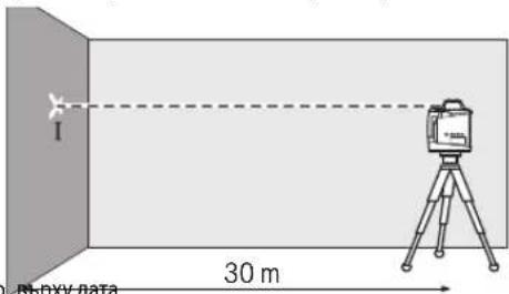
-3aBbptete H3MEpBaTeJIHHypeHa 180°,H3UaKaIte Da ce HnBeIIpa n OTHOBo MapKnpaIte ueHTbpa Ha Na3ePHN IbHu HA CTehata (TOka II).CTpeMeTe CE TOka II da e no BB3MOXHOCT BEPTHKAIIHO Ha, peCn. NOI TOka I.
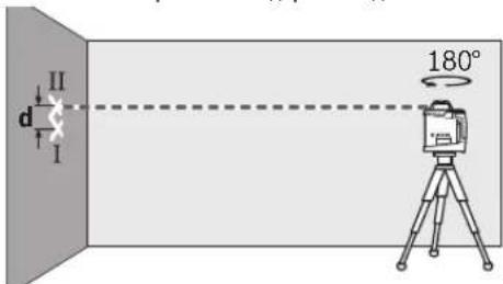
PaNikata dHaBete MapKnpaHn TOnKn I N11 Ha CTeHata DaBa a6cOIOHTHO TOmECTBaHe No BnCOUHa Ha H3MepBaTeHHra ype3a CbOTBeTHaTAtC.


436 |Былгарский
NoBTope npoueca n 3a pyraT aoc. 3a ceta npedn da 3a noHHe H3MepBaHTo 3aBbptTe ypeHa Ha 90^
Ha pa3ctoHHe 30 m MaKcMaIIHO DOYCTHMOTO OTKIOHeHne e:
30m× ± 0,1mm / m = ± 3,0mm.
CneIOBATEHNOeONyCTHMOpa3NkatadmexkyTOUKHeI HIIPIBcKOOTDBeteH3MepBaHnHa6bde He NOBeeO T 6mm.
PpOBePka Ha ToUHocTtHa HnBEnHpAne npu BepTNKaHNO nonoxenHe (GRL 500 HV)
3a npOBepkata CEHyKaTe OE CBO6OHa 30Ha 3a HmEpBaHe Bbpy TBbpda OCHOBA nped CTeHa C BncoHn 10 m. 3axBaHETe KbM CTeHaTcOTBec Ha BbKe.
-MoHTnpaIte H3MepBaTeHnHpyeD BBB BepTKaIHO nOIOXeHHe Ha cTaTHB HINr ONoCTabete Ha TBbpda paBA HCObBa.BKIOUcE H3MepBaTeHnH pyeN rno H3uKaAte da ce HnBeHnpa.
-IM3MeCTeTeH3MePBAteHnHaIaIbTaTOHOBcHTbPaBTOPNHkPaHaBBKeToHaOTBeca.Pa3Nkata dMekdyNa3epHnMbUHOtBecaBDIOHNKpHaBBKeToDaBaabCOJIOHTOOTKNIOHHeHa3MEpBATeHnHaYpeoTBePTKaIATA.
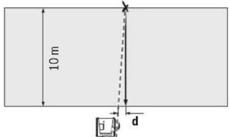
PnH3MepBaHa BncoUHa 10 m MaKcMaIHO DOnyctHMOTO OTKIOHeHHe e:
10m× ± 0,1mm / m = ± 1mm.
Cneobatenho paanikata d Tpa6ba da 6be haMHO 1 mm.
KaHn6pnpaHe Ha n3MepBaTeHNHn ype
OnncanHte No-dony DeIcTBnTp6BaJa ce H3nbHbRaT caMo OT do6pe obuyehn KBAINHmnpaHn nua.Tp6BaJa ce no3HaBaT 3aKoHomePHOCTne npn npOBeKdaHe Ha npOBepKa 3aTOuHOC Tn KaHbPnpaHn HA3MePBatehen HHCTpyMeNT.
H3BpIeTe KaHb6PnPaHTo HA H3MePbAteHHypeC H3KIOUHTENHO BcOka TOHOC TnI To ppeaTe 3a npOBepKa B OTOpH3npaH CEPBn3a eNEKTPOHCTpyMeTHNa Bo. HeoctaTbHoo ToHoo KaHb6PnpaHe Bodn Do rpeKNPiH H3MePbAheTO.
3anoubaTe kAnh6pnpaHcMo aKo Tpr6Ba Da h3BbpWHTe KAnh6pnpaHcHa h3MepBaTeHHy UpeD. CneI KaTo h3MepBaTeHHrT ypeD 6bDe BkIOUeH B pexHM Ha KaN6pnpaHe, Tpr6Ba Da h3nblHInTe KaH6pnpaHeto N3KnIOuHTenHO TOUHO nOdkpa, 3a Da He 6bDat CneI TOBa pe3yJtATHE OT h3MepBaHHraTgpeHH.
YnbTbHe: CnEi KaIb6PnPaHETo HNnKATOpHTe 3a npOBepKa Ha KaIb6PnPaHETo Ce NOBBArTOHBO, KOrATo NOBtOHO Bb3HNKe PnpuHa 3a npOBepKa Ha KaIb6PnPaHETo.
3a KaIIN6bpHpaHETo ce HxKdaTe OT OTeCua CdbnHa 30 m Bbpxy TBbpda oCHOBa nped npaba CTHe.
BnHaH KAnbPpAte BCnKn Ocn (GRL 500 H: oc X n oc Y; GRL 500 HV: ocn X, Y n Z).
Kann6pnpahe na octa X
-MoHTnpaTe H3MepBateJIHHy ypeD BXopH3OHTaIHO NOIOXeHHe Bbpy CTaTHB 63 (He e BKNIOUeH BOKOMNNEKTOBKaTa).
-Noctabete ctaTbHa pa3ctoHnE 30 m nped cTeHata. PnTOBa MapKnpoBkata Ha octa X Bbypx N3MepBaTeHHype Tp6Ba da e nepneHdkyIpyho cnPmo cTeHata.
-BkIIOUeTe H3MepeBaTeHnHnypeI.

HaTHNCHETe eHNOBpeMeHHo 3a np6n.2 s6yTOHHTe KaINb6pnpaHe 25 n3a HaKIOH 18.
p-eiTaKa,ye na3epHnTbU

Ha nncnne ce H306pa38a CBMBoBt3a KaHbPpHaHe Ha ocTa X.
IbBpeMeHaABTomaTHHOTOn HnBEnnpaHe npDynpTeINHHT INHnKaTOp 3a HnBeNpHae 37 Mra.
-ИЗчakайе ИЗмерваелпурд acе снвенира.
C nomouta ha naasepHnna pnpemnHK Hamepe tcepehdata nnHn nofbenexete Bbpxy cteHa BncoHHata ,X1" Ha cpeHATA nnHn.
-3aBbptTe H3MepBaTeHnHa ypeHa 180°6e3 Da npomeHrte BnCOuHnHa Ha CTaNBA.
-ИзчakайтпрдунрдгнггнгнгнгнгнгнгнгнгнгнгнгнгнгнгнгнгнгнгнгнгнгнгнгнгнгнгнгнгнгнгнгнгнгнгнгнгнгнgHnBENpa.
-CnOMOHTaHa na3epHnnaPnmeMHNK HamepeTe cpeHnata nnHnna nOrbeneKeTe Bbpx CYteHATA HOBATA BnCOUHn, X2 Ha cpeHnata nnHn.
-OnpeDeneTe cpeHata TouKa MeKdy BnCOUHNTE, X1" N X2" nNoCTaBeTe Na3epHHN I pIeMHNK Taka, Ye eHTpanHaTa MapKnpoBka 16 Da e Ha Ta3i BnCOUHa.


一
H
-3a Da H3KIIIOHTe Bb3MOXHOCTTa OT rpeWho KAIH6pHpaHe, cIe npKIIIOVAbe Ha KAIH6pHpAteTo Tp8BaJa H3BbpWHTe IpOBepKa Ha TOUHOCTTa Ha HNBENHPaHe (BNXTe, IpOBepKa Ha TOUHOCTTa Ha HNBENHPaHe pPrxOpiH30HTaIHO NIOJOKeHne".cTpaHnca 435).


BbIraPckn|437
AkoOTKIOHeHHeTo npOdbNkBaDaHaNXBbPnI DOnyCTMaTAtpaHnca Ot ± 3,0mm ,npaTe H3MePBATEHnHypd3a npOBepKa B OTOpHnpaCepBn3a eEnKTPOHHCTpymENT Ha Bo.
KannbprapaHa ocaY
-MoHTnpaIte H3MepBaTeHnHrypeBxOpH3OHTaHNO nonoXHe Bbpy CTaTHB 63 (He E BKJIoueH B OKOMJIeKTOB-Kata).
-Noctabete ctaTbHa ha pa3ctoHnE 30 m nped cteHata. PnTOBa MapKnPOBkata Ha oCTa Y Bbpxy n3MepBaTeHNH ype Tp6Ba Da e nepneHnkyIpaHpo Cnpmo cteHata.
-BkIIOUeTe H3MepBaTeHnHpyeI.


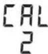
-HaTnCHete eHOBPemHeHO 3a npH6n.2 s 6yToHnTe KAnHbPpAne 25 n3a HAKNOH 20.
HaHcIeCe H3O6pa3raBa CmMBoIbT 3a KaII6pIpaHe Ha ocTa Y.
No Bpeme Ha aBtOMaTHuHOTo HnBeInpaHe npDynpTeHHT HnKAtOp 3a HnBeI npAhe 37 Mra.
-ИЗчakайтЕ ИЗмерВATEнгТурд acе HNBeInpa.
-CnmoaHa Ha naaeHHN pHMeHHK HamepeTe cpeHata nnHn nOtbeHexe Te Bpxy cteHata BncoHHata ,Y1"Ha CpeHATA nnHn.
-3aBbptTeH3MepBaTeHHypeHHa180°6e3Ja npomeHHTe BHCQHNHATA Ha CTaTBA.
-ИЗчakайтпрдунгдггнгИнДИКATOP3aHNBENHPa-He 37da cnpe da Mnraи nM3mepBaTeHNHRTypedacce HNBeHpa.
-CnmooHTaHaIazepHnIpHemHK HamepeTe cpeHata nnHHnIOBeneXeTE BbpxCTeHaTtHOBaTa BncoHNHa,Y2 Ha cpeHATA nnHn.
-OnpeeneTe cpeHata Touka MeKdy BnCOunHIne, Y1" "Y2" nNoCTabete Na3epHNn npHemHHK Taka, Ye eHTpanHaTa MapKnOpBkA 16 Da e Ha Ta3n BnCOUnHa.

HaNcKaIe 6yToHnTe 3a HAKIOH 18 nn20,doKATO INHnKATOpBt 3a CpeDHa HnHn4 43 3anOueHe da CBETn HEnpeKbC Hato. PnB BkInoueHa 3ByKoBA CNrHanH3aunCe yBa HEnpeKbCHa CnHnA.
-HaTHcHete 6yToHa KaIIN6pHpAne 25,3a Da 3anaMeTHe HAcTpOKaTa Ha KaIN6pHpAHeTO.
HaHnCnpeCe H3o6pa3aBA CnMBonbT3a KpaHnKaIINbPnpaHTo.


-3a Da H3KIOUHTe Bb3MOXHOCTTA OT rpeHNO KANH6pHpaHe, cne npNKIOUVAHe HA KANH6pHpaHEToT8Ba daH3BbIPHTe NPOBepKa Ha TOUHOCTTa HA HNBENHPaHE (BNKTe ,PiOBepKa Ha TOUHOCTTa HA HNBENHPaHE pN XOpH3OHTaHNO NOLOXeHHe".cTpaHnua 435).
AkoOTKNOHeHHeTo npOdbNkBaDa HaNXBbPnI DOnyCTMaTa rpaHnua oT ± 3,0mm npeaTe H3MePBateJIHHyep3a npOBepKa B OTOpH3npaH cepBn3 a eJeKTponH-CTpymEnTHa Bo.
KaH6pHaPeHa ocTa Z (GRL 500 HV)
-CnOMOHTaHaOTBeCHaueptaTeBepTKKaHAnHHBbpxyCTeHata.
-MoHTnpaTe H3MePbATEHINHpyeBepTnKaIHO BbpxCTaTHB63 (He E BKJIOUeH BOKOMJIeKTOBkata).
-ПoctabeTe ctaTHBaHa pa3ctoHHe 5-10m nped cteHaTa.
-BkIIOUeTe H3MepeBaTeHnHa ypeI.

-HaTHcHete eDHOBpeMeHHo 3a npH6n. 2s6yToHHTe KaIb6pHpaHe 25 n 3a HaKIOH 18.

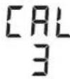
Ha nncnne Ce 3o6pa3ra BA CmBolbT a KaInbpnpaHe Ha ocTa Z.
-Hacouyete CtaTbA Taka,Ye na3epnHrT NbH da npecuHa BepTKaHATA HINHA CTHeHata.
IbBpeMeHaABTOMaTHHOTNHBeINpaHe npdynpTeHNHT HnKATOp 3a HnBepnaPe 37 Mra.
-3aKaIe H3MePBeTENHHTypeD da ce HbEnnpa.

HaNCKaIe 6yToHInTe 3a HAKIOH 18 nn 20,doKATO Na3epHNrTbY cTaHe ycnpoeHn HINrTa HcTeHa.
-Ako He MoKTe Da NoCTHHe TcNOpEDHocT NOaHaTa DbJKNHa, NOBTOpe TnpExOHNHe CTbKn (No3nIOHOHpaIte CtaTHBa, H3uKaAHTe HNBEnHPaHTo Ha H3MePbAtenHna YpeD, NoPaBHe TaepHNa NbC nOMoTu Ha 6yToHHe 3a HAKlaHHe).

-HatncheTe 6ytoHa KaIin6pnpaHe 25,3a da 3anaMeTHe HactpoKata Ha KaIN6pnpaHTo.

Ha nncnne ce H306pa3raBa CmMBoIbT 3a KpaH a KaIIh6pnpaHeto.
-3a da H3KIIIOHTe Bb3MOXHOCCTTa OT rpeWHo KAIIN6pHaPe, cIeN pRkKIOUBaHe Ha KAIIN6pHaPeTo Tpr6BaJa H3BbPHTe IPOBepKa Ha TOUHOCTTa Ha HNBENHpAe (BNKTe, PpOBepKa Ha TOUHOCTTa HA HNBENHpAe npn BeptNaKALHO NONOJEXHe", CTpaHua 436).
AkoOTKNOHHeITo npOblJkaBa daHaDxBbPnIOnyctMaTa rpaHnca 0T ± 1 mm, npdaTe n3MePbATEHnrypeD3a npOBepKa B OTOpHnPaH cEBn3 3a eNeKTpOHnCTpyMeHTn Ha Bo.


438|Бьлгарскn
Yka3aHn3a pa60Ta
13MepBaTeHNHrTypee cBopBXHeC6e3XnHHe HHTep- fec.Tp86Ba Da ce Cn3Ba TnOKaHnTe OprAHnueHn B peKMa Ha NoN3BaHe Ha 6e3XnHn YcTPOCTBA, HAnp. BcamoNETn NnB 60NHn.
MapKnpaTe BnHarToOHO cpeTa Ha na3epHata HnHHa. IInpouHATA Ha na3epHata NHHa Ce npomHe c pa3-CToHHeTO.
HactpoBaheHaMepnTeeHNHn
HaIINCNIIe pa3cTOnHHTo MEKdy paBHHaTa Ha BbPteHe n CpeHATA HNNrCe H3O6pa3raBb [mm] Hn [inch:decetuHo/c np6n].
Hactpoikata B 3aBOda-npOu3BOUHTen e [mm].

HaHcKaIe EINHOBpeMeHHO HeKoIKoKpaTHO 6yToHnTe 3a HAcTpoBaHe Ha TouHocTa 23 n3a HAKIOH 20,DOkATO DCHTHETe XeNaHATA HaCTPOKa.

PnH3KIOUyBaHe Ha 3MepBaTeHnH ypeH hAcToPkata 3a MePHHTe eHNHcN Ce 3ana3Ba.
OuHa 3a Ha6nOdaBaHe HaIa3epHmRbU (DOnbHHTenHO npncnoc6neHne)
OuHnata 3a Ha6IIOJaBaHe Ha Ia3epHnIbU qHInTpIpaT OKoHata CBETnHa. Taka YepBeHATA CBETnHa Ha Ia3epHnIbUc Be B3npHema No-NECHO OT OKOTO.
He h3non3BaIe Ounnata 3a H6nIOdaBaH a na3epnna Kato npedna3n pa6oTH ouHa. Teu ouHa cnkykat 3a no-d6poto H6nIOdaBaH a na3epnna Ib4, Te He npedna3Bat OT hero.
He h3no3BaTe Ouynata 3a H6nIOdaBe Ha na3epHnHa bky KaTO CbHuEBy OHnHa NIN DOkato yuactBaTe ByHHNHO TO DnKHe. OUYnATA 3a H6nIOdaBe Ha na3ePHnHa bky He OcHpyRaB 3aUHTa OT YIITpaBNOJETOBteNbHNOrpaHnYBa3npHemaHTo HA CBETOBete.
Pa60Ta CbC cTaNB (DOnbHnTeHnO npncnoc6bnHe)
M3mepBaTeHnHrT ypeI hMa pe360Bn OTbop 5/8" 3a MoHTnpaHe B xOpN3OHTaIIHO NIOJIOKeHne KbM CTaTHB. NocTaBete OTbpaHa ypeDa Bbpy CtaTHBa H rO 3aTeHETe C BnHTa 5/8" HaCTaTHBa.
PnH3N03BaHe Ha cTaNB 63 cpaTpaPeHa cKaa MoKeTe DaOTHTATE HAcTPOBATE OTMeCTBAHETO NO BNCOHNHa HENOcpeDCTBEHO.
Pa6oTa c npncnocobneHnTo 3a 3axBaUaHe KbM CTHa MOnyna 3a HacOuBaHe (DopbHHTeHnHO npncnocobneHne)
CnE Bd BKnIOUbaHe H3MepBaTeHNHrT yPeI nPoBepBA DaIIe E XOpN3OHTaIHO, PecNI. BePtNKaIHO NIOJKeHne H KOMNeHCpa OTKIOHEHnB PaMKITE Ha IHaNA3OHa 3a ABTOMaTHuHO HNBeIHpAeOT np6b59.3a CEITa HABNTe BNHTa 5/8"62 Ha CToKkata 3a CTeha B OTBopa 3a MOHTHpAe KbM CTaTHB Ha H3-MepBaTeHNHypeI.
3axbaaHe KbM CTHe: 3axBaAaHTo KbM CTeHa ce npenopbya HAp. PnH N3BpUbaHe Ha DeHocTH, 3a KOHTo Ce H3NCKBa BcOcHnA, NO-FONMA OT MAKCHMaHATA Ha CTaHB, PnPa60ta HA HeCTaBnHa OCHOBA Hn Pn HnCnA h CTAHB.3aCeTtza BaXbaHe TnpncOc6NeHTo 3a 3axbaaHe KbM CTHe59 C MoHTiPah N3MePbATEeH ypeD No Bb3MoXHOCT nepHeHNKyIrpHO CNpmo CTHeTA.
3a MOHTnpahe KbM CTHeTAt MoKeTe Da 3axBaHete CToKkata 59C BnHTa 60 KbM NETBa C MaKcImMaHa IInpoUHa 8mm, INI DA OKaHTe Ha DBe KyKn.
MOHTPapa He HA cTaNb: MOKETe Da MOHTnPaTe INPNCIOcO6HHeTo 3a 3axBaUaHa He CTHe 59 CbIoo N KbM CTaNB C NOMOuTa Ha pe36OBHr OTBOPOT3aHATA My cTpaHa. To3N HauHr HA3axBaUaHe ce npenOpbVa Oco6eHO aKO paBHHata Ha BbTeHe Tp8Ba Da bDe NoIpaBHeHa CNpMo DAeHa NHnR.
C NOMOHTa Ha npHCNOC6NeHHeTo 3a HAcOuBaHe MoKTe Da
H3MeCTHe MOHTnpaHnHa N3MEpBaTeHneYpeD BbB BepTKaJIHO
HAnpaBHeHne (Pn3 aXBAaHae KbM CTHe),peCn. XOpH3OH-
TALHO HApBaHHe (PnH MoHTnpaHne Ha cTAHb) B DnA1a3oH
OT pN6b.16 cm.3a Zeta Pa3BnTE BnHTa 61 Ha npHCNOC6NeHHeTo 3a HAcOuBaHe, N3MeCTe N3MEpBaTeHNHa YpeDo
KeNaHATA No3mU NH OTHOB 3aTeHHe NTbH 61
Pa6ota c H3MepBaTeHa JETBa (DOnbHHTenHO npncno-c6nHe) (BHXTe FHyp a H)
3a npoBepKa Ha paBHHHOCT HnH 3a MapKnpaHeTo Ha HAcNOHn Ce npeOpOByBa H3NoI3BaHTo C potaUHOHHHa3ep HaH3MepBaTeHaJeTBA 55.
B rohpnKa pHa MePntenHata nata 55 pa3rpaepha OTHoCnTeHa cKaHa (± 50cm) . HynBaTa Bn BnCOuHa MoKeTe Da ycTahOBHTe C n3MeCTBaHe Ha DoJIHHa KpA. TaKa MOrat da 6bDaT OTUHTAH HENOCpeDCTBeHO OTKIOHEH NOT HOMHaHHaTBAncOHNHa.
Ppimepn
IpoBepKa Ha dbn6oHHaHa H3KOnn (BHXTe pHr.1)
-ⅡOCTaBeteH3MepBaTeHnHpyeD Bbpxy Cta6nHa OCHOBA HINI I MOHTnpaTe Ha CTaTHB 63.
-Pa60ta cbc ctaTnB: NocTaBeTe H3MepBaTeHnHrypeTaka, ye Na3ePnHrT Nb Da e Ha KeJahAnata BnCOunHa. PneHece- te, pecn. npoBepeTe BnCOUnHata BbB BTOpata ToHca. Pa60ta 63 ctaTnB: OnpedeTe pe3NkAra Bbb BnCOnHa Mekny pa3eHnHaNbHpepeHTHaToKc. PneHeceTe, pecn. npoBepeTe H3MepeHaTa pa3NkA Bbb BnCOnHte BKeJahAnata ToHca.
PnH3MepBaHe Ha roJlmo pa3cTOnHne Tp8Ba BnHaHn Da NoCTaBtE H3MepBaTeHNHypei Ha cTaTHB np6N. B CpeDAta Ha paOHTATAIIOU, 3a da orpaHnHTe rpeWKata B H3MepBaHETO.
-Пи рабotingа Вьрху Hecta6HHeN IOI MOHTnpaite N3MepBaTeHHHpyeBpxy CTATNB 63.BHIMBaJIte CnCTemata Anti-Drift da e akTNbPapa,3a n36erHete rpeuHN N3MepBaHn npa3MeCTBaHe Ha OCHOBaTn pIn cBtpeCENHa H3MEpbATEHHype.


BbIrapckn439
OtctpaHbAbeHa noBpeDn
KoDObe 3a rpeuKa
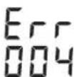
PnBb3HKnBaHe Na npo6IeM KOJbT 3a rpeIka Ce n3NcBa Ha dncIeJe.
-OTcTpaHbAbeHa npo6IeMa(BHXTe,OTcTaPbABeHa npo6IeMn")

- CneT TOBa HATNCHTe eHOBPemHHO 6yTOHHe 3a peKHM "CpeHaIHHn"19 n 3a 3ByKOb CaHnHaN3a- cna H3Byka 24.
Ako DepeKbTe oCTpaHEn ycIeHNo, Cbo6ueHHeTo 3a rpeWka H3ue3Ba n ce CTapTnpa ABTomATHHOTO HNBeHnPaHe (BHXte, ABTomATuHO HNBENPae, cTpaHua 431).
Ako npobemb octane, trpaBda npedeTe H3mepBaTeHHypea npOBepKa B otOpHnpaH cepBn3a eneKtpOnHCTpyMeHTHa B0w.
H3o6pa3aHaBnKo- PpO6nEM OcTpaHBAhe doBe 3a rpeuKa
| 001 Octa X Ha n3mepBaTeHnY uepe i n3BbN dIa- na3OHa 3a aBTOMaTNUHO HNBellpAne oT npi- 6n. 8,5% (5°). | -Поме�е позицура Na n3mepBaTeHnY uepe cnpa octa X. |
| 002 Octa Y Ha n3mepBaTeHnY uepe i n3BbN dIa- na3OHa 3a aBTOMaTNUHO HNBellpAne oT npi- 6n. 8,5% (5°). | -Поме�е позицура Na n3mepBaTeHnY uepe cnpa octa Y. |
| 003 (GRL 500 HV) | Вьв ВerteКален ржим octа Z Ha n3mepBa- telHnY uepe i n3BbN dIa-na3OHa 3a aBTOMa- TNUHO HNBellpAne oT npi6n. 8,5% (5°). |
| 004 След поян ha nO3HnYrTa n3MepBaTeH- nHHT uepe i pod haknoh B nobeeu ot 8,5%. | -Поме�е позицура Na n3mepBaTeHnY uepe. |
| B pexIM Ha hakNoH cnрmo edha oc e hap- XbprHe NduAn3oHa Ha hakNoHa ot ±8,5%. | -Натскaite 6byToHa 3a hakNoH 18 nii 20,doKato Na din- Pnle Ce n3HnIe StcHIOCT Ha hakNoHa od 8,5% (BvIXte ,HaCtpoJa Ha hakNoHa", cTpaHnca 431). |
| 005 HndxbpHeHa maksimamNo donyctHmata npodbJxHtENHcT 3a aBTOMaTNUHO HNBell- pane. N3mepBaTeHnY uepe He moke da ce HNBellpAr aBTOMaTNUHo. | -Поставе n3mepBaTeHnY uepe bvpx cStbniHa ochoba nII rgo MOHtpaite KbM cTaNIB. OCHOBaTa He Tp86Ba da Bn6pIPA. |
| 006 He ce doctHra JekanHr Ta BtBn B pexIM Ha Ha- knOc H cnpMaO edHa oc. | -Поставе n3mepBaTeHnY uepe bvpx cStbniHa ochoba nII rgo MOHtpaite KbM cTaNIB. OCHOBaTa He Tp86Ba da Bn6pIPA. |
| 007 | PotaunOHnHa Tnaba Ha Ia3epa He ce Bvptn. |


440|Былгарский
Hs6pa3aBaan Ko- PpO6nEM OTeTpaHbAbe DoBe 3a rpeuKa
Service scule electrice
Strada Horia Macelariu Nr. 30-34, sector 1
013937 Bucuresti, Romania
Ten.: +359(0)700 13 667 (Быларск)
_aKc: + 40212331313
Email: BoschServiceCenterBG@ro.bosch.com
www.bosch-pt.com/bg/bg/
TpaHcnpTHpAne
BknouhenbOKOMnKToBkataNHTHeBO-ooHHaKymnyTaPONHbATEPNCaB0xbataHaH3NCKBaHNrTaHOPMaTHBHTeDOKyMeHTH,Kacaeu npOyKTNCOBNIeHaOnaCHOCT.AkymnatOpHTe6bEPnMOratda6bDatTpaHCnOPTnpAHNOTNotpe6ntenHaNy6nHmecTa6e3doNbHnTeHNpappeHTENH.
Pn TpAHCNOpTnPaHe O TpTeH CTpaHH (HaNP. nPbB3dyWe HtpaCnOPT HIN NON3BaHe Ha KypnepeK yCnyH) HMa CneuHnn H3NCKBaHHa KBM ONaKOBaHETo H 06o3HaayBaHETo Hm 3a cetaC ce KOHcyTNpaIe C eKcnept B cbotBeHTa Obnact. Hnpaaate AkymnatOPHN batePHn CaMO aKO KopnyCbH M He e NobpeH. hOnpauTe OTKPHTN KOHTHN KJIEMn C nePAnH NeHTn H onaKOBaTe AkymnatOPHN batePHn TaKa, YdA He MOrTa Ce H3MeCTBa B ONaKOBkata CN.
Mon, cna3BaIte cbuo n donbHnHTeHNn HauhoHaHN npednncaHH.
Баразуванe

COrneIOna3BaHeHaOKoHnHa cpea potaunOHnHnAT na3ep,3apnHOTOyCTPOINBOHHnNa3epHNTPnEMNHK Tp6BaDa 6bDat npedabAHn 3a npepaB0Ka HcBdbPkaUNTECEBTAX CypOBHH.

He 3XbprnIte potaunOHnnnaIa3ep,3apndHOTO yctpoCTBO,la3epnI npneMnK u6aTePN/akymynaTOpHN 6aTePNIpiN 6tOBnTE OTnabu!
Cama 3a ctpaHn ot EC:
Cbflncho Ebponecka npektnBa 2012/19/EC n3mepeBataHn ypeHn Cbflncho Ebponecka npektnBa 2006/66/EO akymnatopHH nn oNknOBehn bateHH, KOto He morat da ce n3noi3Bat noBeue, Tpr6Ba da ce cb6npatOTdHNO Hda sbDat noDnaraHH naNoxDxaI npepa6oTKa 3aONJIO3TOBOPBAHe Ha cbbpkaunte Ce TBx cypoBHn.
Donycka ce demoHTnpaHTo Ha BrpaHeHte akymnaTOpHH 6atepHH cAmO OT KBaHnHnpuHH TexHmC cIeN npHPOOCb6pa3HOTo Hm HxBbPnHE. PnO TBapHHe Ha Kopnyca Ha n3MepBaTeHNu ypeD ypeBt MoKe da 6bJe NOBpeH.
3a da n3BaIte akymnatoPHTa 6atepno OT n3MePbTeHINypei, npenTOBA T rpa5Ba Da e pa3peHa HAnbIHO. Pa3BInTE BnTobete Ha Kopnyca Hro OTbOpTe. 3a da npedToBpaNTe KbCO cBeHNHeHne, n3BaKaIte KJIeMITE Ha akymyIaTOphata 6atepna NocedeOBaTeHo eHa no eHa n 3oJNpaTIe NoIOcHte. DOpnPi pN PbIHO pAspeKDaHE B aKymnatoPHTa 6atepna OCTaBA OprAHueHo KOINueCTBO OCTaYeh3apd, KOITc Ce OCBO6OxDABA pN KbCo CbeHNHeHne.
AkymynaTopHN HnO6NkHOBeHH 6aTePHN:
Li-Ion:
Mon, cna3BaIte yka3aHnTaBpa3en,TpaHcnpTnpaHe", ctpaHnca 441.
Ppabata 3a n3MeHenHn 3aNa3eHN.
442|MaKeDoHcKn
MaKeDoHcKn
OnncHa coOpxHHa
Be36eHochn HanoMeHH 443
PotaunoneHnacep 443
PoiHauch 3a 6aTeepn 444
IacepcKn npneHmHK/daJeunHcKny npabyBaay 444
Onnc Ha npoh3BOoT h MoKHOCTa 445
YnTope6a co cooDBetHa HameHa 445
Potaunohn Iacep GRL 500 H 445
Potaunohn nacep GRL 500 HV 445
Iacepcn npneMHNK LR 50 445
Nnyctpaunja Ha KOMnHOeHTN 445
Texnukn noataoun 446
MOnTaKa 447
PonHeHa 6aTePNrTe Od MEPnOT ypeH nacepcknO
PoiHHeBa6aTePiJaTa 448
HaonomeH3aONTHMaHNOKOpHeBa6aTepeHnTe..448
Ynortpe6a 448
CTabaBe BO ynoTpe6a 448
IocTabyBaBeHaMePHNtYpei 448
KopncTeHe Ha MeHnOtypeD(BuNcnCnKa C) 448
OnepaTHBeHpeKHM 448
RTC (Real Time Clock)-6atepnja 450
AanapMeH cHCTeM 3a aWHTa oKpaXb4 450
AknBnpaHe ha anapMnHOT CnCTEm 3a 3aHTNa od Kpax6a 450
CnyaHa npHMeHa Ha anapMHnOT CnCTeM 3a 3aHTTA OJ KpaK6a 450
Pnka3Ha npOBepKa Ha KaH6pauijata
ABTomatcko HnBEnpaBaBe no BKnIyBaBaTeTo.....451
ABTomatcko HnBEnnpaIbe 3a BpeMe Ha pa6oTata .452
PeknHa KocnHa co eHa ocka .452
IocTabyBaBeHaKocnHa. 452
PekHM ha ueTpmaHnHaHHja (Bmncnka D) .452
3a6p3yaBaHbHa npoHaoraBeTo Ha cpeDnHnata HnHjia Ha nacepcknot pnpemHK .453
ANTH-NIN3raquKn CnCTem (ADS) 453
DeaekTHBnpaHbHa aHTH-NH3raKnot ChTeM 453
PnkaHa peaTHBbTa BcHna (BnN cNkaF) .454
Pa6oTeHe co nacepcn npHemHK 454
PaoNo-Bpcka nomery MePHNOtypei daneuHcKnOt ynpabYBaay/nacepckntepnemHmui 454
IooecyBaHBe Ha cHrHaHnHTo h/tnaHocTa .454
I36epe te ja noctabkata Ha npka3ot 3a cpeuHa nnju. .454
Pnka3Ha npabeu .455
3aunTHa dyHKnJa Strobe-ShieldTM .455
O3hauybahe. 455
OcbetnyBaHe Ha ekpaHOT 455
PnucBpCtBuBaHe co DpxKa 3a MepHn IeTBn (Bnu Cnka G) .455
PpOBePKa Ha ToUHocT Ha MePHNtYpeI 455
BnjaHaHaToHocTa 455
PpOBePKaHaTouHocTaPnHNBEnHpAbe Bo XOpN30HTaJHaNoIox6a .456
IpoBepkaHaTouHocTaPnHNBenpaBe BO BepTKaHaNoox6a(GRL500HV) 456
KanibpnpaBeHaMePnHOTypeI 456
Kannibpupahe Ha X-ockata 457
Kanibpupahe Ha Y-ockata 457
MaKeNoHcKn|443
Kan6papahe Ha Z-ockata (GRL 500 HV) 458
Cobetnpa6oTebeTo 458
IodecyBaHbHe Ha npka30Ha eHHnnte 458
Iacepcn ouHna (onpeMa) 458
Pa6oTeHe co cTaNb (onpeMa) 458
Pa6oTeBe co sIneH npKaun eEnHHua 3a HapamHyBaBe (onpeMa) 458
Pabotebe co mepha letBa (onpema) (BnDn cInka H) 459
PpHmepn 3a pa60ta. 459
PpOBepKaHaDnla6OuHHaTaHaIpaEeXHnTeJaMn (BmCnkaI) 459
OrcpaHbBaBeHa npeKn 459
PpeKn co KoJ 3a rpeuKa. 459
PpeuK6e3 KoD 3a rpeuKa .460
OdpkByBaBe H cepBnC 461
OdpjyBaBe n uHCTeBe 461
CepBncha cnYkBa n COBt npKOpHCTeHe 461
MaKeDoHnJa 461
TpaHcnpT 461
OrctpaHbBaBe 461
Be36eHocnHaNoMeHN
Potaunohen nacep

CHTe ynatCTBa Tpe6a Da CE npouHtAAT H Da CE BHIMABA Ha HNB,3a Da MOKe 6e36eHNO H 6e3 onachocT Da pa6oHTe co OBOJ Mepenypei. DOKONky MEPHNOTypeI He ce KOpHCTn CornacHO npHNOXeHnte
HhCTpyKuHH, MoKeJa ce HApUH cyHKnjuTa Ha BrpadeHHTe 3aHTTHM MeXAHmH BO MEPHNOT ypeJ. He ja oWtetyBaJte 03HaKaTa 3a npEynpeyBaHe ha MEPHNOT ypeJ. IOBPO 4YBA.JTE FN OBNE YNATCTBAI INPEDAETE FN 3AEJHO CO MEPHNOT ypeJ.
BHHMaHHe -IOKONky KOpNCTHe DpyrYpeDn3a NOeCyBaBe HpaKyBaBe OCBeHOBDe HabeDeHnte HNNONHaKBN NoCTaKNH, OBa MoXe Da DoBeDe Do Onacha H3NoKeHoCT Ha 3paYebe.
MepHnotypeceHCnopaYbaCoHaTnnc3a npedynpdeyBahe(O3NaueHoHa npHKa3OT Ha MepHnotypeHa rpaΦnKATAcTaHa co 6poj8).
Laser Radiation Class 2 do not stare into beam IEC 60825-1:2014 <1mW,635 nm
DOKONKYKCTOTHaHaleHHnata3a npdeynpeyBahe He e Ha BauHOT ja3NK, BP3 Hero 3aneneTe ja HaneHHnata Ha Baunot ja3NK nped npbata ynotpe6a.

He ro hacouybajte nacepcknot 3paK Ha
Hnla HnN XnB0THn He nOnerdnyBaJte
DnpekTHo BO Hero HnH HeroBaTa
peoekcnja. Taka MoKe da rnaaclenite
nUata, da npedn3BnKate HecepeKn nn da
rnoOtETne OHTe.
Dokonky nacepcknot 3pak Docnee do ouhnte, Behdaw Tpe6a da rH 3aTbOpHTe n da ja TprHete rnaBata od nacepcknot 3pak.
He Bpuwe HNKaKBn npomeHH Ha nacepcknoTypeI.
He rKopnCTe Nacepcknte Ounna Kako 3aHTTHOounna. Nacepcknte Oounna cnykat 3a noo6po npeno3HaBahe HaNacepcknot 3pak, Ho He 3auTHTyBaat OJ NacepckTO 3paueHbe.
He rKopnCTe Nacepcknte Oouna KaO ouHna 3a coHue nn NaB Go Coo6pakajot. Nacepcknte Oouna He daBaat cenocHa UV-3aHTTa n ro HaMaIyBaat npeno3HaBaHbTo Ha 60n.
MepHnOT ypeI cmeI da ce nonpaBa cAmo od ctpaHa Ha KBaIIHΦNkYBaH CTpyeH NepcoHAn Co OPHINAHn pe3epBHH DeIOBn. CaMo HA ToJ HauHH Ke 6uDte CInyphn BO 6e36EHOCTa Ha MEPHnOT ypeI.
He n octabajte decaTa da ro Kopnctat nacepcknot Mepen ype63 hazop. Moke da rnaacnenat npynte Nua npaHbHMaHne.
He pa6oTeTe Co MepHOTypeB OOKINHa KaIe NoCTOn OnaCHOCT OJ EKcNIO3nJa, KaIe HMa 3anaHBn TeuHOCT, rAC Hn npaunHa. MepHOTypeC03dBa NCKPN, KOIMoKe da ja 3anaTnPpABTa Hn napeTa.

3aHTTeRoMepHnOypeoTOnHHa,Ha np.0dONrTOpaJHO H3NoKyBaBe Ha CONHeB 3paun, orAH,BODa H Bnra.PocToon onachocT oEckno3na.
Pn NorpeHNO KOpHCTeBe, MoKeJa HcTeue TeuHoCTa od batepjuata. N6BerHyBaJte KOHTAKT co Hea. JOKoKy cnuyajHO DoJeTe BO KOTAKT CO TeUHOCTa, HCnNAKHeTe ja Co BODa. JOKOKNy TeuHOCTa DoJe BO KOTAKT Co OUHTe, No6apajTe nekapca nomoi. NcTeeuHATA TeuHOCT od batepjuata MoKe Ja npEiIM3BbKA KOKHN npTuAn nn HsropeHnI.
DOKONky ce ouTeTH 6aTeepjata Hn He CE KOpHCTN npabHHO, OHe a MoKe Da n3ne3e naPea. BHeceT CBEX BO3dYH DOKONky HMa NOBpeDeHn ODHeCETe Hn Ha Nekap. NaPeata MoKe Da Hn HApaaHn DnHnHTe natuTa.
HanoHete ja 6atepujata co hcnopauahnoT nonha. DOKONky nonhauot koj e npnaoroe H a ede cooDBeteh BnD 6atepn, ro Kopncnte co dpyr 6atepn, nocton onaCHOCT od noxap.

444 | MaKeDoHcKn

He n npnncybaje mepnoht ypeHn
eHnata Ta 3a nacepot Bo 6nn3Ha Ha nejcmejkepn. MarheTOT ha mepHnOHT ypeHn
eHnata Ta 3a nacepot co3daBaat none, KOe MOKeJa ja Hapuyin cyHKuJaTa Ha nejcmejkepnte.
MepHnotypeNueHnataTa6Na3aIacepotdpxkete rnoNoanekyOgMarHeTcKn HocauHnNoDatoOnuHypeNOCETINBnHaMarHET.lopadnBnJnHaJIeToHaMarHETnTeOJ.MepHnotypeNueHnTa6NaHaIacepotMoKe dadoJeDo HeNoBpaTHn3arybHaNoDatoUte.
Ponha3a6atepn

Ipoountajte rH cHTe HanomeHH yNaTCTBa 3a 6e3eHnoct. TpeuKNTHe HactaHaTH KAKO pe3yTTaOD HeNPdPjxByBaBe Do 6e3eHNOCHHTe HanomeHH yNAtCTBa MOKe Da npEdu3BkaaTe nekTpuhen yDap, noKap H/nn TeuKn nobpeH.
Oboj nonhaue He e npedBndeH 3a KopncTebe Od ctpaHa Ha deca N Iuca co HamaIeHN PcnxNcK, fH3uKN Hnn MeHTaHH cnoc6HOCTn Hn HEDOBONHOCKyCTBO H3HaEbe. Oboj nonhaU MOKe Da Ro KopNCtAT Deca HAd 8 roDHH KAKO HIIua co HamaIeHN F3uKN, ceH3OpHN MeHTaHH cnoc6HOCTn Hn HEDOBONHOckyCTBO H3HaEbe, DOKoNKy Ce NOd HAD3Op OD Iuca ODROBOPHN 3a HNBHata 6e36Ednoct Hn Ce NOdyeuHn 3a 6e36eHNO paKyBaHe co nonnaOT n Pa3bnpaat OnachOCTHTe KOH MoKe da npOH3ne3at nopadn Toa. NaKy IOCTOn ONACHOCT OJ NORpeHNa ynotpe6a n Nobpei.
HaRnEpyBaJTe rN Deuata 3a BpeMe Ha KopHcTeHbeTo, HcTeHbeto N ODPxYBaHbeto. Taka ke ce Ocnrypate nKa Deuata HeMa da CN IrgpaT co nonHauyot.

Nonhaot dpxete ro nodaeky oddoa Hbnara. HabneryaBaHTo Ha Bda Bo nonhaot ro 3ronemyba pnaKOT oEneKtpuehen ydap.
Hanohe ro mepnnotypeedco hcapaahnoT nonna.
Opxybaje ja nctota Ha nonHaOT. JOKKY ce HBAkna, NOCTOn ONaCHOt OJ eNEKTPuH yap.
Ppe cekoe Kophctehe, npoepete ro nonhaot, Kaenot n npnknuyokot. He ro Kophctete nonhaot, Dokonky npHmteTne OWTeYbaHa. He ro OTbopajte camn ONHaOT n OCTabeTne Ro nnonpaBka Kaj KBaHnKByan CTpyueh nepcohan KoJ Ke KopHCn caMo opHnHaHN Pe3epBHN denOBn. OWTeHnOT nOJaHau, Ka6en n npnknuyok RO rOlenMyBa pHsNKOT 3a enEeKTPuye H yap.
He ro Kopnctete nonHaouot Ha necho 3anaHb noDnora (Ha np. XapTjha, TeKCTHNTH.) ODHOCHO 3anaHb OKoHnHa. NocToH onaHcOCT od noXap 3apaHn 3aTOnIyBaHbTo Ha ypeoT oTO npOn3nerya npn PONHeBTo.
DOKONky ce ouTEn 6atepnjata HnH He CE KOpNCTH npabHHo, OHe MaOKe Da H3ne3e napea. BheCe CBEX BO3dyx NDOKONky HMa NOBpeHn OJHeCte Rn Ha nekap. Papeata MoKe da HnHaipasHn DnHnTe naHTTA.
Nacepckn nphemHK/daJeHHckn ynpaByBaay

CHTe ynatCTBa Tpe6a Da ce npouHtaa H da Ce BHMaBa Ha HNB. IOBPO UyBAJTE IOBNE YNATCTBA.
MepHnOT ypeI cmeE da ce nonpaba cmo od ctpaHa Ha KBaHnФHKyBaH CTpyeH NepcoHAn Co OPHnHAnH pe3epBHN DeOBn. CaMo HA ToJ HauHH Ke 6uTe CnHyPhn BO 6e36eHocTa Ha MEPHnOT ypeI.
He pa6oTeTe co MePHHOTypeB BO OKOINHa KaIe NoCTOn onaCHOCT OeknIO3nJa, KaIe HMa 3anaHBN TeuHOCT, fAc Hn npaHHa. MePHHOTypeCo3daBa NCKPN, KOIMoKe da ja 3anaTnPaBtA Hn napeTa.

3aHTTeRoMepHnOyPeIoTOnHHa,Ha np.0dONrTOpaJHO H3NOxYBaBe Ha COUHeBn 3paun, orAH,BODa H Bnra.PocToon onachocT oEcknoaJa.
Pn NorpeHNO KOpHebe, MoKeJa HcTeue TeuHocTa od batejata.36BerHyBaJte KOHTAK Co Hea.10KoNky CnyaJHO DoJeTe BO KOHTAK Co TeuHocTa, HCnNAKHeTe ja co Boda.10KoNkY TeuHocTa DoJe BO KOHTAK Co OOHTe, NObapajTe nekapca NOMoi.1CteehaTa TEuHOC Td 6otejata MoKe Ja npEIM3BnKA KOxHn INpTaunnn nn HsropeHnU.
DOKONky ce ouTEn 6atepnjata Hn He ce Kopncn npabHHo, od Hea MoXe da H3ne3e napea. Bhece Te CBEX BO3dyx H DOKONky HMa NOBpeHn OJHeCte Hn Ha Nekap. Papeata MoXe da Hn HApazHn DnHnHTe natuTa.
HanoHHe ja 6aTePjAto co HcnopauHnOT nonHa. DOKONky nonHaoyot koj e npnaIaoJeH ha eJeH cooDBeTeH BnD 6aTeHN, ro KopncHTe co dpyn 6aTePN, noCTOn onaCHOCT OJnoXap.


MaKeNoHcKn|445
Onnc ha npOn3BoDoT mokHocta
Ynotpe6a co cooDBeTHa HameHa
Potaunohen nacep GRL 500 H
MepHNoTpeJe HameHeT 3a OndeYBaBe H npKaKyBaBe Ha TOUHN XOpN3OHTaJIHN JINHH.
MepHnOTypeHaMeHET3aKOpHeBeBOHaBBopeWeH npocTOp,MeYToaMOKeJaCePnIMeHyBaN BO BHaTpeWeH npocTOp.
Potaunohen lacep GRL 500 HV
MepHnOypeIe HameHeT 3a OnpedyBaIe N npOBepKa Ha TOUHN XOpN3OHTaJIHN BNCINH, BEPTKALHI INHH, INHHN 3a H3paMHyBaBe I NaCEpCKN TOUKN.
MepHnOTypeHaMeHET3aKOpHeBeBOHaBBopeWeH npocTOp,MeYToaMoKeJaCePnIMeHyBaN BO BHaTpeWeH npocTOp.
Jaacepckn nphemmuk LR 50
Iacepcknot nphemnke hamehet 3a 6p3o npohaofabe Ha potnpaqukn Iacepckn 3paun H3a daneuHcKO ynpabyBahe Ha potaunnoHOT Iacep.
IacepcknOT npHemNk e nOroDhen 3a KOpNCteBb BO BHATpeuH HnADBOpeuH nPoCTOp.
Hanomeha: LR 50 cnyHK n KaO Nacepckn PnpemHnK KaKa OdaeeuHcKn ynpaBauBa.3aNoobpaUHTINBOcT HaONHCte N yanCTbata, BO cneHNOT TeKT LR 50 e 03Haueh KaKO "Nacepckn npemHnK".
NlyctpauijaHaKOMNOHEHTU
HymepnpaheTo Ha KOMNHOENTHe Co CnHK Ce OJHecyBa H npka30 Ha potaONHOHT Nacep, NOHaOT Nacepcknot npemHHK Ha rpaHNUKHe CTpaHnU.
Potaunohen nacep
1 BeptnkaHa nacepcka nnHjia (GRL 500 HV)
2 V3ne3 Ha nacepcknot 3paK
3Пизma-noknoeuc(anyMHnHym,CTaKNO)
4LEDanapm npotnb kpaek6n
5 KOHTaKTn 3a nonHeBe Ha nacepckNt npHmNHK
6 CtaHua 3a nonHebe/yyBaBe 3a nacepCKHot npHemHHK
7 Nacepckn 3paK
8 Hatttnc 3a npéDynpéDyBaHe Ha IacepoT
9 Cepnckn 6poj ha potaunohen Iacep
10 PnФaT 3a cTaNBoT 5/8"(BepTknAnHO) (GRL 500 HV)
11 Pokloneu 3a npKJyOkoT 3a noJIHeBe
12 PnpaT 3a cTaTnB0r 5/8" (XopnOHTanHO)
13 Konque Reset
14 O TBOP 3a npnKnyokot 3a nonHebe
Iacepckn nphemnK
15EkpaH
16 Cpeiunha 03naka
17 Konue 3a BknyuBaBe-HcknyuBaBe
18 Konue 3a kocnHa rope
19 Konue 3a pekmm Ha zentpnaHa nnHnJa
20 Konue 3a kocina dony
21KoNue3apeXMMHaMmpyBaHbE
22 Konue 3a anapm npotnb kpaekb
23 Konue 3a noctabyBaHbe Ha ToUHOCT npMpeheTo
24 Konue 3a CnHaleh ToH/rlnachOCT
25 Konue 3a kaih6paunja
26 PnemHNO nOe 3a IacepckNoT 3paK
27 Cepnckbpoj hnaacepcknoTnpneMHNK
28 Kohtaktn 3a nonHehe
PnHKa3H eneMeHTn Ha JacepCKHot nphemHHK
29 Pnka3 3a HanoHHeTOCT Ha 6aTePnJaTa Ha potaunckno nacep
30 Pnka 3a HanoHHeoCT Ha 6aTeepjata Ha nacepcknot PnemnK
31 TeKCTyaneH npKa3 3a KocHa/tpeWka
32 TeKCTyaJIeH npNKa3 3a peNaTHBHa BnCHHa/HTepBaJI Ha KaIIbpaIJa
33Прикада за радиьрсka
34 Pnka 3a npdeynpeyBahe 3a TempepaTpya
35 Pnka3a HntepBaHn Ha KaJIbpaJHa
36 Pnka 3a anapm npotnb kpa6a
37 Pnka 3a npeynpdeyBahe 3a HbElnpahe
38 PokaTeT 3a npEynpeyBaHe 3a ydapn
39 Pnka 3a npabeu, Napcepckn 3paK npeky cpeMnHaTa nnHja
40 Pnka 3a npBeu, Napcpcn 3paK noCpeHnHaTa nHHja"
41 Pnka3a peKHM Ha KocHa
42ПикадаразекимпацетралнлИннJa
43 Pnka3 Ha cpeuHnHa Tnnnja
44 Pnka3a peKmHaM npBaHe
45 Pnka3 a cHrHaen Toh/rraCHOCT
46 PnKa3 Ha ToUHocTa npm MpeHe ,ΦnHO
47 Pnka Ha ToHocTa Pn Mepe He, CpeHo
48ПинkaЗHAToUHOCaПпМepeHbe_rypo
Nonnay
49 Ponha
50PnKnyOk3a nonHebe
51PnKnyoK
52 Ctpyen npnKnyok
Onpema/pe3epBnDenoBn
53ДржачзмернiteлтBN
54 3aBPTka 3aФИКСРаБe HaДрЖСУТЗмЕнTeЛТВИ
55 Mepha IeTbHa HrapeJekHnO tacep
56 3aBpTKa 3a npuBpcTyBaHbe Ha dpXkaOT 3a MePHHTeNETBn
57 Nibena Ha ndjkaoy 3a MepnHe IeTbN
58 Pamkn 3a BmTeHyBaHbE Ha IacepckNt npneMHNK
59 SIneH AnpKau/epinHnua 3a n3paamHyBaBe*
Bosch Power Tools 1609 92A 4DX(28.3.18)

446 | MaKeDoHcKn
60 5paФ 3a npuBpctyBaHbe Ha sIyHnOtdpJka
61UpaΦHa eDHHuata 3a H3paMHyBaHbE
625/8"upaHa sniHnOt dpkaU
63 CtntB
64 Naperpckn Ounna
65 Kypep
*OnnHaata onpeMa pNkKaHnHa cNKnHTe He e den oD ctAnapnnot 06em Ha cnptopaka. KomnNethata onpeMa moKeJa ja hajte BO hauata Iporpama 3a onpeMa.
Texnukn noaToun
| Potaunohen lacep | GRL 500 H | GRL 500 HV |
| Бpoj на дeн/артник | 3601 K61 A.. 3601 K61 B.. | |
| Рабтоно поLE (разиус) | ||
| - бezлесрки пгимнik okoly. 1) | 10 M | 10 M |
| - се ласерскп пгимнik okoly. | 250 M | 250 M |
| Точность рпн Новлины 2) 3) | ||
| -хоризотално | ±0,1 MM/M | ±0,1 MM/M |
| - ветшикално | - | ±0,1 MM/M |
| Тишично поLE на самонивени ралы | ±8,5% (±5°) ±8,5% (±5°) | |
| Тишично врeme на Новли ралы | 15 c 15 c | |
| БрзINA на рotaциja | 600 min-1 | 600 min-1 |
| Реким на косина co edna ocka | ||
| (се поесува п配电у тасатураи и погиазот на ekраиот) | ±8,5% | ±8,5% |
| Точост 2) | ±0,1% | ±0,1% |
| Аларmen сисем за заштуд од кражба | ● | ● |
| Прике за Intервалы на кальрациja | ● | ● |
| Temпегатура прп равoting | -10...+50°C -10...+50°C | |
| Temпегатура прп скалдраиhe | -20...+70°C -20...+70°C | |
| релатива влажноct на Воздунот макс. | 90% 90% | |
| макс. орета вида вида вида вида вида | 2000 M 2000 M | |
| Класа на пасер | 2 | 2 |
| Тил на пасер | 635 nm, < 1 mW | 635 nm, < 1 mW |
| Остanyва ще на пасерская ралниja | 0,4 mrad (целесен aron) 0,4 mrad (целесен aron) | |
| Ø Пасерск Зрах на Илесенот OTВOP okoly. 2) | 4 MM | 4 MM |
| Опсер на орета видафальциа | 863-870 MHz | 863-870 MHz |
| Дачина на Испараве макс. | 20 mW | 20 mW |
| При卦ат за с�试овot | ||
| - ветшикално | 5/8" | 5/8" |
| -хоризотално | - | 5/8" |
| Төхина сordасно EPTA-Procedure 01:2014 | 2,3 кr | 2,3 кr |
| Димензи (Должinaх x Ширпина x Висиha) | 234 x 217 x 194 MM | 234 x 217 x 194 MM |
| Вид на заштуla | IP 56 (эаштоа od пави прсанье на Вoda) | IP 56 (эаштоа od пави прсанье на Вoda) |
| Актулатор | Питонm-jонска | Питонm-jонска |
| Номнален habон | 7,4 V | 7,4 V |
| КалачтET | 3 Ah | 3 Ah |
| Бpoj на bateриски кели | 4 | 4 |
| Вретмerteье на павота okoly | 25 у | 25 у |
| 1) Рабтоно поLE (разиус) може досян поради нековлени уменови на okолина на с�ухи на вадиота (нарр. Діректа иложеньост на сончеву заши). | ||
| 2) пи 20°C | ||
| 3) по дожина на оскITE | ||
| Серскnot Бpoj на с pineфальционата пioчka 9 сухи за щасна идenteинфальции на вадиот мера у preced. |

MaKeNoHcKn|447
| Ласерский пreamнок/Далочины уравыч | LR 50 |
| Бpoj на дeн/артник | 3601 K69 A.. |
| Прием на браунов дοлжинь | 625-645nm |
| РавOTNO поle (разиус)3)2) | |
| - Ласерский пreamнок с рotingскпacep | 250 M |
| - Далочины уравыч | 150 M |
| Приемен arол | 70°(±35°) |
| Точность по мераиме赦"3) | |
| - Поставka „фино“ | ±1 MM |
| ±2 MM | |
| - Поставka „сре dio“ | ±3 MM |
| ±5 MM | |
| - Поставka „губо“ | ±7 MM |
| ±10 MM | |
| Галемпа на ekранот | 62x31MM |
| Приемна пошниа | 100x18MM |
| Temпература по рамота | -10°C...+50°C |
| Temпература по скадиралье | -20°C...+70°C |
| peлathва влажноct на Воздунхов Маск. | 90% |
| Маск. оретахва висна пекуpeферента висна | 2000 M |
| Опсer на оретахва ph装配вениja | 863-870 MHz |
| Javина на ИсторICALmaцк. | 20 mW |
| Поставка за akтувираобе на рекIMOTпашиваьe | |
| - Калочьа на не се р�птосякнипodолюо od 30 ми. | ● |
| - НEMA пreamн на ласерскnot зракпodолюо od 30 ми. | ● |
| Аларmen сichtем за зашпда on od крахба | 0-150M |
| Приема за итегвали на калбрацида | |
| Текина сordлесноEPTA-Procedure 01:2014 | 0,3 KM |
| Димензни(Далочина x Шерпinaх x Висна) | 152x77x32MM |
| Вид на зашпда | IP 56 (разшпда odправи и рссань на ВODа) |
| Актулатор | Пинums-JOHSCa |
| Номинален налион | 7,4V |
| КалачтET | 1Ah |
| Бpoj на бateриски келл. | 2 |
| В��етаеные на рамота okoly | 254) |
| 1) Раб�тоно� по le(pадиус) може по се hamали поади помен�ниу calobи на поал�у висна ус�ови на поал�у висна (нарл. дірійта на помен�пот на сончеви заци). | |
| 2) зашино od pactоjasною помен�у ласерскnot римени и роташиноюл пасер. | |
| 3) по оданешиноct od 30 M | |
| 4) по дадятынрano осветлу вись на поалот | |
| Серсьнот loь 27 на сіпіduфік��оноота піочь січь за щасна indentніduфік��ліа на вадиот ласерскп рименик /вадиот дади绚нску undayabua. |
| Полnahу | |
| Б Proj ha дeн/артikl 2 610 A16 4.. | |
| Врeme ha nonHebe | okoу 3 u |
| Hanoн ha nonHebe ha 6aTeprnja t | 12 V- |
| Стува за nonHebe | 5 A |
| Клaca ha 3aStitga | ☐/☐ |
MoHTaxa
Ponhebe Ha 6aTePNHe Od MepHnOTypeI nacepcknT nphemnk (Bnu Cnkn A-B)
He KophcTepeT nonHau. IcnopaaHnO tnonHa e npnaoroe HnBaBpaeHata nHTyM-jOHcKa batepna Bo BawHOT MepeH ypeI.
BHMMabajte Ha eneKtpnHnot HanoH! HanoHt Ha H3BOPOT Ha cTpyj Mopa Da OTOBAPA Ha OHJ KOJE HabeDen HA cNeuNkauHOHa TPOKA Ha NOnHauOT.
BHIMAHME
MepHnoTypeHnacepckHot
PnHmHHK CMeaT Da Ce NOnHaT CaMo
BO CYBN BHaTpeHn HPOCTOpHN. Kabenot 3a nonHe he He HaMeHET 3a nonHebe BO HaNBopeWeH PocToP nNn BNaxKa OKOJIHa.
HanomeHa:BatejataHa MeHnOT ypei nacepcknoT nphemHK ce hncopayBa noyhanoneta.3a da oBe36eHte MaKcImaIeH KanauTe Ha Batejata, nped npBATA ynotpeba HAnonHete ja eNocho.
JHym-jOHCKHe 6atepn MoKe da Ce HAnonHAT Bo cKeoe BpeMe, 63 da ce HaMaHn HNBHOT Pok HaYnotpe6a. IpeKInOT npn NOnHeBeTo He n HaHTyBa Ha 6atePjata.
Pnka3 Ha ccoToj6a Ha hanoHetaOCT
3a da ce npnkae coctojbata ha hanoHneocT ha batepjuata Ha MEPnOT ypei nIacepcknoT pneMHNK, MEPnOT ypeM opa da ce Bknyu (Bnu, BknyybaBe", ctpaHa 449).
| Прикази на схрано | Знayец e Kanaцитet | Приoctаны Врeme 3a Мереь okoly. |
| 29 | Батерида e цelenocho нанолнета. | 60-100% 15-25у |
| 30 | ||
| 29 | Батерида e денимно нанолнета. | 40-60% 10-15у |
| 30 | ||
| 29 | Батерида e денимно нанолнета. | 20-40% 5-10у |
| 30 | ||
| 29 | Батерида e денимно нанолнета. | 10-20% 2,5-5у |
| 30 | ||
| 29 | Батерида трава да ce нанолни. | 0-10% 0-2,5у |
| 30 |
448 | MaKeJoHcKu
Iokony MepHNOtypeE ncknyueh,aIacepcknOT npemHHK BO cTAHUATAa 3a nonHe/uyBaHe 6,cocTojBaTa Ha HANHT HeoCT Ha BatepNJata ce npKaKaYBa Ha CneDHNOT HAuH:

-ПиTHСHTe ro konTuTo 3a peKHM Ha MmPyBaH e 21doEka He ce CnyuHe CnHAne ToH. Ke ce npKaKAT npKa3te 3a coCtoj6bTa Ha HanonHEToCT Ha bATEpnjata 29 n 30.
I05c.ocBETnyBaHToHaekpAHOIT NOBTOHOeNCKnyuBa.
PonHebe Ha 6aTepeHjata
-NCuHCTeTn H3BaIkaHHTe KOHTaKTn 3a NOJIHeBe CO CyBa Kpna.
- PnKnyokot 51 cTabeTe ro BO npEbnHeHnot OTbOp Ha nonHaOT 49.
MepHnOTypeMOeJaCeIOnHHHe3ABuCHOoJNaacepckNt npHemHK, aNaacepckNt pHemHKcMo 3aeDHO Co MepeHnOType.
Mepen ypei (Bnui cnka A):
-OTbopete ro noknoneout 11 Ha OTbopot 3a nonHebe 14.
CTabete ro ctpyjHnOtn npknnyok 52 BO npknnyuHnIaT a, npknuyokOT ha nONHaOT 50 BO OTbOpOT 3a NOnHeBe 14.
Iacepckn npmHnK (BnDcNkaB):
-CTABEToIacepckNt npHemHK BO cTaNuata 3a nonHe6/yyBaHe 6.
- OTBopete ro noknoneot 11 Ha oTbopot 3a nonHebe 14.
-CTabeTe FO CtpyJHnOtn PnPKNlyQOK 52 BO PnPKNkyHnIaTa, a PnPKNlyQOKOT HA NONHaOT 50 BO OTBOPOT 3a NOnHeBe 14.
Пикази На ekpahot
3nauebe
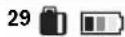
BaTepuHteKeceHaNoHnat.
3a BpeMe Ha npocot Ha nonHebe cerMeHTIe TpeKaaT eHn No dpyr.
IIO nonHebeTo MEPHNOr ypeN HncepcknT npHemHK ce NCKnyybaaT.
Iokonky He ro ynoptpe6yBaTe, H3BaTe re noHaot OCTpyja.
3aunTeTe ro nonhaoyoBnara!
HannomeHHaONTHMaHIO KOpHCTeHe Ha6atePHnTe
Cknnapjte ro MepnHtpei nIacepcknO nphemHK caMO BOIO3BOJIeHNTe rpaHnHaTe mtnepaTpya, BNn "TexHnKn noatao". Hanp. He nOCTabJe IeTHo BpeMe Bo aBTOMO6NIOT.
CkpaTeHTo BpeMe Ha pa6oTa no nonHeBeTo nokKaYBa,Ke Ka 6aTePnJa t e nToPoWeHa mOpa Da Ce 3aMeH.
BHHMaBaJTe Ha HAnOMeHInTe 3a OTcPaHyBaBe.
Ynotpe6a
CtabaheBoynotpe6a
3aHTTeTHeMHeHnOteHnaacepckHotnphemmNk ODNbIaHdpeKTHo H3NOxKyBaBe Ha COHyBn 3paun.
He rH3IOxoyBajTe MEPHNOT ypeH nacepcknOt nphemHHK HaekCTpeMHN TemnepaTyHn OcunnauBO Bo temnepaTpya. Hanp. He rH octabajTe Donro BpeMe BO aBTOMo6NIOT. PnI rONMe OcunnauN BO
Tempepatpata, octabete rH MEPHHOT ypeI n IacepcknO npemnhk HajnpBO Da ce akImMaTH3npaAT, nped da TcBnte BO yNtpe6a. PnE ekCTpeMHn TemepaTyPi NIOOCuHaauN BO TEMpepatpata, ppeuHocTa Ha MEPHHOT ypeI n IacepcknOT pneHmHK MoKe Da CE hapyui.
H36erhybaje rnyapnHe nnpBpyBaHa Ma MepHnot ypeI. IocHHn HADBoPeuHN BmJahJaHa MePHnot ypeI, nped Da ro ynoTpBe6te 3a pa6ota, cekoraui h3BpwTe KOHTpOHa ToOHcTa (BnDIn "Pobepka Ha ToHOCHa MEPHnotypeI, ctpaHa 455).
IocTaByBaHBe Ha MePHNtypeD
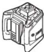
Xopn3oHTaIepeKMM (GRL 500 H/ GRL 500 HV)
BepHTKanEnpeXMM (GRL500HV)
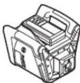
IocTabete ro MepHnOypeHa cTaNHa nOJNora BO XOpH3OHTaHa H BepTHKaHa NOnoX6a, MoTHnpajTe Ro Ha CTaTHB INH Ha SIneH DpKaay 59 co eHNHuaTa 3a HpaMHyBaHe.
Bp3 ochoba Ha BnCOKaTA TOUHOCT Ha HNBENHPaHe, MePHNOT ypeD peAHPa MHORY OCETNBO HA NOTPECN INPOMEHn HA nonOx6bata. BHIMABAJTe HA cTaNHa N03HUNJa HA MEPHNOT ypeD, 3a Da Ce N36BerHAT PneKNH Ha pa6oTa Tnopadn DOONHHTENHO HNBENHPaHe.
KopHeBeHaMepHNoTypeD(BNnCnkaC)
MepHnOTypeCe ynpaByBa npEky konuHaTaHa nacepcknOt npHemHK. YnpaByBaHeTo Ha MepHnOTypeMoKeJaCe BpWHnDpeKTHo (nacepckNtO pIneMHNK eCTaBeH BO cTAnuata 3a nonHebe/yBaBe 6) INI npEky paNo-Bpcka (nacepckNtO npEMHK dykuHOHp a KaKO daJeHHCKy npaByBa).
OnepaHBeHpeXHM
CnCTeMoT Od MepeH ypeH nIacepckn npHeMHNK nO3HaBa
3 onepaTHBnpeXHHM:
-Pa6oTeHpeXHM
CnTe cyHKcHn Ha MepHNOtypei nIacepckNt npHmHK ceakmbnpaHn.
BnDn BknyBahe", cTpaHa 449.
-PeKHM Ha MmpyBahe
NoBeKeTo FyHKnHa MeHnO TpeCe DeeAekTNBpaHBO nepnooMkC.2aca3aDa3awteDat eheprna. AApMnHOT CnCTem 3a3aHTHa OD KpaK6a H anHIN3rauKnOT CnCTem CE N NOhATamy kTbnpaHn. CTe NoCTaBKn (CnHahHe ToH/TracHOCT,TOHOCPT Pn mpeHBe, KcOHN hT.)Ke ce3auYbaat. BUnn,PexmHa MnpyBaHe",ctpHa449.
- NcknyeHo
CHTe FyHKUH Ha MepHNO T ypeH N lacepCKHOT nPnEMHHK ce DeakTNBpaH.
BnH, NcknyBaBe, cTpaHa 449, n, ABtOMatcko NcknyBaBe, cTpaHa 450.


MaKeNoHcKn|449
BknyyBaBe/ncknyyBaBe
He ro hacouybaje 3paKOT cbETnHa Ha Hnua nn XHBOTnH He NorneHyBaJte dHpeKTHO BO Hero,dypn HN od ronema oDanaeuehoct.
He ro octabaje BknyeHnOT MepeH ype63 Hau3Op HcknyuTe ro no yonTp6a. Dpyrnte nua MoKe da ce 3aclenat OndacepcknT 3paK.
Hanomena:ПпсдягуnotребитмернотypedТpe6a ceKorauДаИЗВPsHTe ПОвЕрkaHaTOUHOTa(BINn „ПовЕрkaHaTOUHOTHaМернOTyped",страHA455).
CtBaBbe Bo ynotpe6a
HanomeHa: PnH nCnpakata MePHNOT ypei nIacepckNt npHmHK ce cnapeHH (= IacepckNt npHemHK MOKe da H3BpWbA phKcHn Ha daneuHcKn ynpaByBa).
3a da ce 3auteeH eHepnja, BknyBajTe rH mepHnotypei nacepcknot pnhemnKc camo DOKOKy H KOPCTNTe.
BknyBaHe

-3a Da To BknyuHTe MepHnOT ypeI, CTaBeTe Ro NacepckNt PnHemMHK BO CTaHNUta 3a NOnHeBe/yyBaBe 6 Ha KpaJ pPiTHNCHe H KaONueTo 3a BknyuByBaBe-NCKnyuBaBe 17.
HNN
-CTaBeTe RoIacePcKNot PnpeMmHKn BO CTaHnIcata 3aONHeBe/yyBaBe6NIOBtOPho N3BaIeTe rO. IToTa,3a Da rO BKnyHTe MePHNOT ypeI,BO pOK oD 30 MmH.Mopa Da rO pInTHcHETe KOnyTeo 3a BKnyBaBe-HckNyBuBaBe 17.
Pe3yntaT
- Cnte npka3n Ha ekpaHot KpaTko CBETHybaaT.
3aNoCHyBa ABTomATCKOTO HNBEnIpaHe (BnDn ABTomAtNka 3a HNBEnIpaHe",cTpaHa 451).
-AHTH-NIN3raqKnot CNTeM Ke ce aKTbNpa 30 c no ABToMaTcKTo HBeBnPaHe (BND, AHTH-NIN3raqKn CNTeM (ADS)°, cTpaHa 451).
Itoa mepnot ypeinncpaka nacepckn 3paK 7 (GRL 500 H) nnnacepckn 3paK 7 n3paKaHa BepTKkanaTa 1 (GRL 500 HV).
HcknyuBaBe

-ПиNTСКAJTe FO KOnYeTo 3a BKnIyBaHBeNCKNHyBaHBe 172c.
Pe3ynTat
-Potaunjata connpa, nacepcknot 3pak e ncknyeH.
-Cnte npka3n Ha ekpaHOT NOCBETnyBaHbeto Ke ce HCKNYaT.
HanoMeHa:doKoNkyceHcknyatIacepCKHOTnpHEMHNKpoTauNCKHOIacep,3a da CE BkNyHnLacepCKHOTnpHEMHNK,MOpa NOBTOPOHa ce CTABN BO CTAHNuTa 3a noJIHeBe/yyBaBe6.
PexmHaMpyBaHe
Co NOMOHa NaIacepckNt PIneMHNK, MepHNOtypeM MoKe Da ce NomeCTn 3a MaKc.2 Hac BO peXm HA MnpyBaHe.

-3a BknyuBaHe Ha peKIMoT Ha MmpyBaBe npHTCHETe Ha KOnyTe 3a peKIM Ha MmpyBaHe 21.

Bo peKHMOT Ha MmpyBaBe Ha IacepcknO TnpHemHK CBETn PnPKa30 3a peKHM Ha MmPyBaBe 44 N nPn akTNBpaH aIapM npOTNB KpaKb6a DOnONHTeHcBETn PnPKa30 3a anAPMHOT cHCTe 3a 3aHTTtA oJ KpaKb6a 36.

PnA kTNBpA hApMEn CnCTeM 3a 3aWHTa OJ KpaKbHa MepeHNOtypeDtpenKaLED-cjAnuKata Ha aIAPMO TpoTHB KpaKb4.
CnTe npRyH npHKa3H nIacepckNt 3paK ce NCKJyuEHN.AHTH-NH3raqKHOT CnCTEM,OCTaHyBa aKTbBpuH.

-3a npeknHa pekMOT Ha mnpyBahe OndHO BpHTCHTe Ro KOnTeTo 3a peKm BO MnpyBaHe 21.
PexnmoHa mpyBaBe aBOMATCKN Ke ce Bknyu,doKoKy nacepcknot 3apK He NOMHe Hn3 NOIeTo 3a II pHem 26 noJIOro oD 30 MHN. HnKONHbata Ha nacepcknot npHemHK He ce npHTncat noOIOro od 30 MNH.
Hanomeha:ДOKOKky nacepcknot nphemnki poatacknot nacepe Bo pexHm Ha mHyBaBe noDIOro 2u.ДbTaKe ce NCKIyUaTbOMATcKn.3a Da ro BKlyuHTe nacepcknot nphemnki Mopa nobTOpho da ro CTaBITE BO cTAHnUta 3a nonHe6/yyBaBe 6.
Ctanhapnata noctabKa npnncnopakatae [PhHKunjata Ha peKHM Ha MmpyBahe e deakTNbpaHa].

-3aakTNBnPaBeHaФyHKunjaraHa pexHM Ha MnpyBaHe, nH BkIyueH MepeH ypei, npHTNCheTe ro NCTOBpEmeHO KOnHTo 3a BkLyUyBaHeNCKIyUyBaBe 17 H KOnHTo 3a peXHM Ha MnpyBaBe 21 OkJy 2 c.
HaekpaHot 3c.Ke ce npkaKyBa HOBata coctojba[phiKunjata Ha peXnM Ha MnpyBaBe e aKTINBpaHa = SLP On] Ke ce npKaKe npKa3 copeXnMOT Ha MnpyBaBe 44.
IocTabkata He ce 3auyyBa npn NCKnyuYbaHeTo.MepHnoT ypeD cekoraCtaptyBa CO DeakTHBnPaHa FyHKunJa Ha peXHM Ha MMpyBaBe.
-3aDeakTHBnpaHaeHaftyHKunjataHapeKHMHaMnpyBaHe,piu BknyuehMepeH ypei,piHTHCHeTe roNCTOBpEmeHO KOnHTo 3a BknyyBaHcckNyBaBe17 H konHTo 3a peKHMHa MnpyBaHe 21 Okny 2 c.


450|MaKeDoHcKn
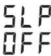
Ha ekpahot 3 c. Ke ce npkakeyba HOBA t coctoj6a [fynHKnjaTa Ha peKMM Ha mpyBaBe e daekTbnpaHa = SLP OFF] n Ke ce npkaKe npka3 co pexHMOt Ha mpyBaBe 44.

ABTomatcko HcknyuBaHe
MepHNOtypeNnacepcknoTnpHemHKABOTMATCKCe HcKnyuBaat npn OpeHEn yCNoBn (pezytat BnN "McNuyuBahe" ctpaHa 449):
-MepHnOTypeCeHaoraNoIroO2.5uHaBOp OJ NOIeTO3a CaMOHNBeINpaHeN KOIOrHa TpeKKa KJ npOn3neroON HcToTo He eOTcPahET (BND ,OTcPahyBaHe Ha npeK, cTpHa 459).
-ПиakTNBnpanpeKIMHaMpyBaBeMePHNtypeI He e npHTCHAT BO pOK OJ 2 Yaca.
-AHTH-NH3raQKNOtCnCTeMaekTbBHpahNoDOnrOo2,5yaca.
-MepHnOTypeCeHaofaHaBOpOgIpaHnUteHa paBoTHa TemnepaTpa.

Ipea ABtOMATCKn Da Ce NCKnyat MePHNOTypei IacepckNOT pINHEMHNK,OCBEN CnHNAHNNOT TOH, Tpeika PpeynpdeyBaHeto 3a TempepaTpyata 34 OKony5c.
No aBtOMaTCKOTIO NcKJnyuBaHbe:
- Nouekajte Dojeka MePHNtypei NacepcknOT npHemHHK He Ce Hajat NOBTOPO BO rpaHnHTe Ha pa60Ha TeMnepaTypa.
-ДOKOKу eNotpe6Ho,ODHOBO NO3HNoOHpaTe ro MepHnOT ypeI n NOBtOPO BknyeTe ro.
RTC (Real Time Clock)-6atepuja

DOKOKIy NO BKNUYBaHbTe PnPKa3OT 3a INTEPBAHn Ha KANbpaunJa 35 TpeNk OKOny 10c, RTC-6atePjata n BrpaedHnot akymnatop ce cnaBn. INTEPBAHOT 3a KANbpaunJa Hce KOHTPOINPA NOBeke.
-KoHTaKTnpajTe ja OBnacteHaTa cepBncha cnJx6a Ha Bosch.
AnapMeH cnCTem 3a 3awTHTa oKpax6a
CnCTEMOT OJ MepeH ypeH nIacepckn npneMHNK co NOMOW Ha DaBa 6e36eHOnCHMexAHHHMn ja IpeBHeHnpa KpaXbata:
-MepHnOTypeMoKeJaCeKoHTpOInpaCaMoIpeky NacepckNtPnpemHnK,6HejHHeMaKoHTpOInHOneHa MePHnOType.
-ДOKOLKYМернnotypeспомecTNODpepeHTHaTATOka,МернnotypedNlacepckNOTnpemHKNCINHAN3HpaATakcyTNUHOHNB3yEnHO.
AkhBnpaBe Ha anapMHHOT ChTeM 3a 3aHTHa oKpKa6Ba
CtanhapnHaTnoCTaBn npH hCnpakata e [AnpMHHTcHTEM3aawHTTAoKpax6aEeakTNbpuan]

-ПиВКИЧУЕМЕЧЕппгИССЕТЯ КОПЧETО 3a anapm npOTnB KpaX6Ba 22. АларMHнOT ChTcEM 3a 3auTnTa OД Крах6Ba e akTNBnPah.
Pnka30 3a anapm npotnb kpa86a 36 n LEDCjanaHkata Ha anapmot npoTb Kpa86a4CBetaT.
IocBaKaHa anapMHNOt CHTeM 3a 3aHTnTa oKpaKa6aKe ce 3auyBa pH NCKJIyUyBaHbTeO.
3a DeakTHBpaHpe npHTCHeTe Ha KOnyTo AApM IpOtnB kpaK6Ba 22doKe a E BknyeH ypeoT.
CnyuHa Ha npHMeHa Ha anapMHHot CnCTeM 3a 3aHTTa oKpKa6a
YnToPe6a Be36eHocen MExaHH3am
MepHnO typeB KnyeH. H
MepHnOrypeJe BO peXMM Ha MMpyBaHe.
AnapmHnO TcIeMa aKTHBnPaH PnKa3OT Ha anapm 100TMB Kpa6b36
KOHTHHynpaHO CBETN LED-cjnaJnKata 3a anapm npotnb kpaXb4 Ha MePHNOypei NOEKA TpEnka
MepHnoTypee HCKnyueH.
IacepcknOt npneMHNK eNCKlyueH He E BO CTaHnTa 3a
nonHe/yeBaBe 6.
AnapmHnOT CNTeM e DeakTNBpuh
Pnka303a anapm npoTHKpax6a
36 Hema da ce nojabn
LED-cnjannukata 3a anapm npotnb Kpaxba 4 Ha mepHnoT ypeI He CBETN
Iokony MepHnOypeNce npdBnKNO MeTOKaJe e noCTaBeH 3a NOBeKe O5 cek, npA kTNBpuA nApMeH CnCTem 3a 3aHTTaOg KpaXb6a, ce AKTNBaP aCnTeMOT 3a anapM:
-0d MepHnOT ypeI nIacepckHot npHeMHNK Ke ce HcnpaTH eEH CnHAnEh TOH. HBTO Ha 3ByuH npHTncOK HA CnHAnHnHOT ToH, KOeHTo e OueHTo co A, I3HeCyBa do 110 dB(A) H He MoKe da ce peryInpa pNeKy NoCTabkata 3a fnaChOCT, KoJaUTo ce KOpHCTs 3A HopMaHnHOT CnHAnEh TOH.
He ro dpkTe nacepcknOT nphemnK 6n3y do yboto! InaCHNt ToH MoKe da ro OWTEN CNYXOT.
-CHTeOnepaTMBHnФyHKuINcSe6NoKnpaAT.

-LED-cjajnukata3a anapm npotnb kpaixba4Ha MePHNOyep Tpenka 6p30.

-Пикадот Ha anapmot npotnb kpa6b 36Ha nacepcknotnpemHnK Tpenka.


-3a NcknyBaBe Ha aKTHBnpaHOT aIapM nPHTHCHe Ha KOnTeO 3a aIapM IpOTHB KpaX6a22.
CnHaJIHHOTOnIpeKHyBa.
CHTe onepaTHBn FyHKcMn Ce ne6loKnpaA.
CnTe nocTabKn Ke ce pecetnpaHa cTaHapdHn nocTabKn PnBknyBaHbeto(BnDn BknyBaHe"CTpHa449).
AnapMHNOCTEM3a3aHTNTaOJKpaX6Ba NOBTOPOCe aKTINBnPa.
PnKKa3n 3a npOBepKa Ha KaHn6paunjata (npeynpeyBahe 3a KaHn6paunja)
Iokonyk KaII6pauijata Ha MePHNOT ypeM Opa da ce npOBepn, Taa ce pInkaKayBa NO BKNyUyBaIbeTo, HA ekpaHOT Ha IacepCKNt PInEHMN K O NOMOu HA pa3NIuH N pINKa3N BO KOMbHaunja co pInka3OT „CAL".
HanomeHa: Cen3OpHTe 3a npdynpdyBaHBe 3a KaIbpaunja (INTEPBnHa KAn6paunJa, TemepaTyHa Na cKnlaHpaHe, Bn6paun Ha MEPnHOT ype) ce AKTHBn No nPbTO CTBaHBe BO yIOTpe6a.
Ppka3HaekpaHOT PpeynpeyBahe 3a kann6pauija
PnHnHa

CBETN

Pnka3c
HHTepBaJIHHa
Kannibpaunja 35
CBETN
HInTePbAnOT Ha KaNn6paunJa (Ha ceKoN 12 Meceu) e nCTeueH.

CBETN

PnPKa30T3a
PnpeynpeyBahe 3a
6atepnjata 34 cBETN

CBETN

Pokaataenot3a
npedynpeedybahe
3a ydapn 38 CBETN
Ipo KpaTkoTO BpeMeTpaeHe Ha npHka3OT,ce racat npHka3HTe 3a KOthpOHa KaHbpaUjata NOBtOpHO Ke ce npHkaXaT Dpyn PO BknyuBaHeto.
3aTCKPbAbe Ha npKa3nTe 3a npEynpeyBaBe 3a KaH6paunja
IMate MOKHOCT Da Tn 3aTcKPHeTe PnHKa3Ne IOneKa He Ce noJABN NOBTOPO npuHATA 3a npeynpeyBahe 3a KaHH6paunja.

-Додактpae npdenpyBaHbTeTo3a
Kannbpaunja, npntnckajte Ha konueto
Kanibpaunja 25 okony 2c.
Pnka3te 3a KOHTpOHa KaHbpaunjata Ke ce npKaKaT Dpyn OTKaKO NOBtOpHo Ke Ce noJABn npuHaTa 3a PpeDynpDeYBaHeTo 3a KaHbpaunja.
MaKeDoHcKn|451
Ipenopaayn HauHH Ha noctanyBahe no npka3a KOHTPona Ha KAn6paunjata
Pa60THn Yekopn BnDn
CTpaHa
1KoHTpOHa HToUHcTa npn HbEInpaBe 455
2a OtctanyBaHeto od 30 me BO paMKHe Ha MaKcHMaHNO do3BOJeHTe rpaHnO od ±3,0 mm: 3atckpNaBaBe Ha npKa3He 3a npEynpeyBaBe 3a KaH6paunja 451
2b OtctanyBaHeto od 30 me haDboP od MaKcMaHNo do3BOneHIne rpaHnO od ±3,0 mm: KaH6paunJa Ha MePHnoTypeI 456
3b KoHTpOHa HToUHcTa npn HnBeInpaHbe 455
4b IIO KaIIb6paJjata, OToCTaYBaHbEto 0d 30 m e BO pAMKHTe Ha MaKCHMaIHO 0o3B0NEHHTe rpaHnO od ± 3,0 mm: MoKe Da ce paBoTn Be3 rHyBeHe Na neuNHOCTa.
IIO KANHbpaunjata,OTCTanyBaheToO
30 me cè yuITE haDBOP od MaKchMaHHO
do3B0eHnTe rpaHnUo 0 ±3,0 mm:
OCTaBeTe rO MePHHOT ypeD Ha KOHTpOJa BO
HEkoja OJ CepBCHNTe Cnyk6n Ha Bosch
BnOBn ynotpe6a
TeK Ha oCKHe X H Y
TekoHa ockte XnYe 03haeHnD potaOnHaTaIaBa Ha KYKNUTeTO.
Potaunohen pekmn
MepHnOTypepaOToNcoΦKCHa6p3HaHa potaunja (600MH.1),koJaHTo e nOrOHa 3a npImeHa Ha IacepcknOt pIneMHNK.
IperneHa BnOboHapeXHM
- ABTomaTnka 3a HnBEnIpaHe NO BkJyUbaHeto/3a BpeMe Ha pa6oTa
- PekHM Ha KocnHa co eHa oKa
-PexnHa ceHTpaHnaHHja
-AHTN-NIN3raUKN CnCTEm (ADS)
-ПИИСКИ ржим (Line Control) BO BepTKKana (GRL 500 HV)
AbTomatka 3a HnBelenpaBe
ABTomatcko HnBEnHpaBe NO BknyBaBeTo
ПОВКИЧУВАБЕТО,МЕРНОТYPEDАВТOMATСКЛЯпOBЕРУBA хориэталната пожбдгИЗрмHyBa_HEРмнHHTe BO NONETOHa CamOHINBENIPAhe od OKony 8,5% (5°).
3a Bpeme Ha HnBEnIpaHbTeTo TpeNka
Pnka303a npdeynpeyBahe 3a
HINBENIPAbeTo 37.
GRL 500 HV:ПбКуУВаБеTo,МернOT ypeсCAMOCToJHo ja npenO3HabaXOpIN3OHTaHATA OHN.ВePTNKaHATA nonOx6Ba.3a npOMeHa Ha XOpIN3OHTaHATA N BePTNKaHATA nONox6Ba MOne OndHOBo DA noN3UHnHpATE 6e3 da nCKnyuBaTe.


452 | MaKeJoHcKu
ABTomatcko HnBennpahe 3a BpeMe Ha pa6otata
Iokky MePHNt ypeNo Ipomehata Ha noonox6ata ce HaaHaDbOp od noneto Ha cAmOHnBeHnpaHe oO kony 8,5% (5°), HnBEnpapBeTo He e NOBeKe BO3MOxHO n Ke CE npKaeKe Kd 3a rpeuKa (BnDn .OTcTpaHyBaHe Ha IpeuKn , cTpaHa 459).
DOKIky MepHNOY pede H3HNBENPAN, ToJ nOCToJaHO ja KOHTpONIPA xOpH3OHTaHATA NOOx6a. Pn npOMeHN BO NOOx6bata, ABtOMATCK Ce BpH NHBENHPaHe. 3a H36eRHyBaHe Ha NorpeWHM MepeHa 3a BpeMe Ha npOueCOT Ha HNBENPAbE, potaunjata Ha NaacepCKNt 3paK 3aNNPA.
PexHM Ha KocHa co eHa ocka
PnXOpH3OHTaHa NIOJ6bHa MEpHNOt ypeOcKaTa X ABTOMATCKH CE HNBENHpA BO pEKM HA KOCHa CO eHa OcKa. PotaNoHaTa paMHHa MoKe Da ce CBPTN Bo NOpaJe oD ±8,5% OKony ocKaTa X.
Hanomena: Dokonky cakate da n3Bpwnte noodecybahe Ha KocinHATA BeDnHaI NO BknyBaHbETo, MOpA da rno NoeKata ABTomATCKOTo HnBeInnpaHe (BND, ABTomATcKO HnBeInnpaH e no BknyyBaHbETo", CtpaHa 451). Co oBa Ke ce n36erHnat NorpeHHTE MePHn pe3ynTAt.
NoCTaByBaHe Ha KocnHa
IocTabyBaHbTo Ha KocnHa e BO3MOxHO BO NOpaueo±8,5%.

-ПншсHTe ro nДржTe ro KOnчTo 3a KocnHa 18nn20doKeHa Ce npKkaxe cakahata BpeHNOCT Ha KocnHa Ha ekpaHot.

- NOBTOPO OTONYUITE RO KONHTO 3a KOCINHA 18 HN 20.
3a Bpeme Ha NocTaByBaHbeto HA KocnHa TpeKna Ppika30 3a PpeDyPpeDyBaHe 3a HNBenpaHbeto 37.

Pnka303a peKmHa KocHa 41 KOHTHHynpaHO CBETN.

-ПнТИСHTЕ ГИ NGTOBpeMeH O KONHTO 3a KOCINHa 18 H 20.
Auto
IocBaKaTa 3a KocHa e DeakTNBnpaHa. ABTomATCKOTn HBeNIPAhe e aKTHBnPaHO (BnDn,ABTomAtnKa 3a HBeNIPAhe" cTpaHa 451).


ДOKOLKYceпгчекори поу HaЗakocyaBaHbe ±8,5%, Ke ce n3rach npikka30 3a pejIM Ha 3akocyaBaHbe 41 N Ke ce npikkae KoHa rpeSha (BnDn,OTcTpaHyBaHbe Haпрчkn", cTpaHa 459).
PexHMa hIeHTpanHa IHHJa (BnDn CnNka D)
Bo peKIMOT Ha CEHTpAnHa IINHJa MEPHNtype Ce obNyBa ABTOMATCKn Da ja IpOHajde CpeDNuHata IINHJa Ha IacepCKNt PnEMNHc Co DBHXKeHe Ha potaUNoHATA rIaBA Harope-HaOny.

-ПиТИССЕТо KОПЧETо PEXKIM Ha ueHTpAnHa nHHJa 19 OKony 2c.
CTapTyBa ABtOMaTCKOTOBHKeHe HaRopeHaDONYHaPotaunOHata rnaBA.
Ppoec ha npebapybahe:
- Potaunohata rnaBa ce HaBaIyBa do Kpaj Harope.
2.LacepcknoT3paKKeceBKnnyu. - PotaHOnHaTnBaBaCeBpTn HADONY.
4a. Nacepckno3paKdoaraBO KOHTAKT CO INPHEMHOTO NOJI 26 naHaora CpeDnHATA HHHja.
HNN
4b.До КраJOТ Ha nonTo Ha BpTeHbe nacePcKNot 3paK He HAOfA none 3a npHem; Ke ce npKkaKe KoI Ha rpeuKa (BnDn ,OTCTpaHyaBaHe Ha npEuk" cTpaHa 459).
3a Bpeme Ha 6apabeto Ha cpeiHnata
HHJa TpeKApnPKa303a
npdynpdeyBaBe 3a HbEBnnpaBeto 37.
PnKa3He 3a peKHM Ha ceHTpaHa
HnHJa 42 KOHTnHynpaHO CBeTaT.
TOM nacepckno3pak Ke dojne BO KOHTAK CO pHmHOTO N0e 26,do npohoraheTo Ha cpeMnHaTa IHHJa ce cnlya zmbkahe.
Bp3Hnata co KojaTuO ce DnKHe PoTaunOHATA rnaBa Ke 3anpe uTOM nacePCKNt3paKdoJBe BO KOHTaKT Co npHemHOTo None 26.
Ipo npoHaoraheTo Ha cpeHnHata nnHnja MePHmOT ypea ABtOMATCKn To NCKnyyBa peXHMOT Ha ueHTpaHnHa nnHnja. IocTaBeHata KocHnHa Ke ce 3ayBu HKe ce npKaaxe Ha ekpaHOT.

-3a npeknHa pexkmoH a ceHTpaHa nnHja 3a BpeMa npebapyBaHeTo npTncHe Ha konueTo PekmHa ceHTpaHa nnHja 19.
HNN
- NCTOBPemeHO npHTNCHETe Tn KONUHbTa 3a KOCHHa 18 H 20 3a aKTHBnPaHe Ha aBTOMATCKOTO HNBENpaBe.


MaKeIoHcKn | 453
3a6p3yBaBeHa npOHaorAbeTo Ha cpeHnHata HnHnJa Ha nacepcKnotnpMeMHNK
Ppe6apybaheToHa cpeHnHaTnHnJa Ha nacepcknot npemHHK cekoraa 3anOuyBa co dBNKehe Ha potaHOHa raaba Harope,doKoIky nacepcknot npemHHK ce Haora nOc cpednHataaHnHa, a He BO npemHnOto None Ha nacepcknot npemHHK, nacepcknot 3paK Moke da Ce h3BPTN.

-ПиТССЕТоКONЧEToPexIMHaIeHTpAnHa IHHJa19OKOJy2c.
CTapTyBa ABToMaTcKTo DnBHe HaRopeHaDOny HaPotaunHata rnaBa.
-ПиТСССЕТо KONЧETа КОСИнA 20. PoTaMuHaTnBa CeДВИKNHaDAnOу.

13rauKn cHTeM (ADS)
MepHnOTypeIHa aHTN-NINrAqKn CnCTeM, KOJ npN pPOMeH Na noNoXbata OHN. NotpeCN Ha MepHnO T yap INN pN Bn6paun HA NOIOrata rO cnpeyBa HnBEnIpaBeTo Ha npomeHeTATA BcHNa, a Co ToA n IprEwKnte BO BcHNa.

OKony 30 c. no BknyyBaHeto Ha MePHNt OpeDce AKTHBnPa aHTn-IM3raQKNOT CNTEM.
3aBpeMaaknbpaaeTo noneKa TpeNk npka30 3a npdynpyaBaHeTo 3a yap 38. Po aKTHBpaBeTo pKa30 KOHTHynpaHO CBtN.
Dokolky ce npomehn Beptkannhata nonoK6a nnce peHCTpnpa jak notpec, toraw ce aKTbnpa aHTN-NsraKnOT cnCTem: Potaunjata ha nacepot 3anpa npka30 3a npedyepyBaIbe 3ayap 38 Tpenka.5c. cnyuauBkaIbe od nacepcknoT pneMHNK.

-ПиakTNBpaah aHTI-N3raKCHCCTEM pHTNCHeTe KpatoHa KOnyTo 3a BkIyBaBeHCKnyyBaBe 17.
ABTomATCKOTO HNBENHPaBe cTApTyBa(BNIN "ABTomATcKO HNBENHPaBe 3a Bpeme Ha pa60tata", cTpaHa 452).
Cera npOBepe je Ba BcHnHa ta Ha IacepckNt 3paK Ha pepepeHTHa TOUka N COODBeTHO KOpHnPajTe ja BcHnHaTa Ha MePHNt ypeI.
DeaekTHBnpaHe Ha aHTH-NH3raqKHot CnCTeM
ANTIIN3raKNOT CNTcEM MOKe Da Ce DeakTNBnpa 3a BpeMe Ha pa6oTata Ha MePHNOyep.

-ПнТСНЕТаКОПЧETO3aВКЛУЧВаБe-нСКЛУЧВаБe 17.
ANTHIN3raKnot CNTEm EaekTnBnpaH.
Pnka303a npdynpdyBaBe 3a ydap 38 He ce npkaKaByBa NOBeKe.
IocBaKaTHe Ce 3aUyByBa npn NcklyuByBaheTo.MepHnotypeDceKOrawCTapTyBaCoakTNBpuAn aHTN-Ⅱr4aKN CnCTem.
JIHHNCKpeKHM (Line Control) BO BepTKkana (GRL 500 HV)
BoBepTKaJIHnOT pexHM Ha MEPHHOTypeMoKeJa ja naNo3uHOHPaTe poTuHOHaTa paMHHaDoJX-Ockata 3aEHNocTabHo NopeyBaHe Bo npaba NHHja HnnapaEnHoN3paMHyBaHe.

-3a BpTeHb Ha potaunohata paMHnHa BO npabeu HA CTpeKNITE Ha yacOBHNOT pHTNCHEte Ha KONHTO 3a KOcHnA 18, 3a BpTeHb BO npabeu CPTPOTNBEH Ha CTpeKNITE Ha yacOBHNOT pHTNCHEte Ha KONHTO 3a KOcHnA 20.
I03nHnpaBeTo e Bo3MOxHO Bo pAMKn Ha ± 8,5% Bp3nHaTc,co koajto Ce DBNkn POtauHOtA rnaBa, 3anoHyBa 6abHo N KOHTINHynpaHO ce 3roEmyBa.
PexnHa ceHTpAnHa HnnJa npn HnHnckn pexnM (Line Control) (BnH cnka E)
Bo pexnmoHa ceHtpanHa IHHJa MePHNOTypece 6oNyBa ABtOMaTcKHa ja npohajde cpeHmHaTa IHHJa Ha nacepcknot npemHK Co DnHexeHe ha potauhoHata rnaBa neBO/DecHO.

-ПиNTICHETe ro KOnuTeO PExnM Ha ceHTpAnHa nHHJa 19 OKony 2c. ABTomatCKOTO DBNKeHBe NeBO/DeCHO Ha potaunHOHa TnaBa CTapTyBa.
PpoecHa npe6apyBaIbe:
- Potaunohata rnaBa ce HabaNyaBo KoPaj Ha DecHaTaCTpaHa.
2.LacepcknoT3paKKeceBKnnyu. - PotaHOnHaTnBaCe BpTu HaJeBaTa CtpaHa.
4a. NacepcknoT 3paK Doafo BO KOHTAKT CO INPHMHO T ONE 26 n ja Haora cpeHnHaTa IHHJa. Hnn
4b.До кра joТ Ha noIeTo Ha BpTeHbe NacepckNt 3paK He Haafo nOte 3a npHem; Ke ce npKaKe KOHa rpeuKa (BnDn ,OTcTpaHyaBaBe Ha npEuk",CTpaHa 459).
3a Bpeme Ha 6apabeto Ha cpeiHnHaTa
HHnJa TpeNka PnPKa30 3a
PnpdynpdeyBaBe 3a HnBEnipaBeto 37.
Pnka3te 3a peKHM Ha ceHTpaHa
HnHa 42 KOHTnHynpaHO CBeTaT.
LToM nacepckNt 3pak Ke doJne BO
KoHTaKT CO pnhmHOTo None 26,do
IpoHaoraHeTo Ha cpeNiHaTa LnHa ja Ce
Cnyu aunBaBe.
Bp3Hnata co KojaTuO ce DnKn POtaHOna TnaBa Ke 3anpe uTOM nacepckNt3paK DoJBe BO KOHTaKT Co npHemHOTo None 26.
No npohaofoheto HcpeiHnHa IHHJa MePHnoTypea ABOTMATCKNFOHCJIyUBypeXHMOT HaIeHTpaHnHa IHHJa.

-3a npekHH ha pexkmoT ha ceHTpalaHnHa 3a BpeMe Ha npebapyBaBeTo npITncHeTe Ha KONHeTo PekmHa CEHTpalaHnHa nHnJa 19.
HNN
454 | MaKeDoHcKn

-ntOBpEmHO npTHcHTe rKoNnHaTa 3a KocHa 18 n 20 3a aKTbHpaHe Ha ABTomATCKOTO HBeHpaHe.
Auto


3a6p3yBaBe Ha npOHaorAbeTo Ha cpeMnHata NHHJa Ha nacepckNt pneMHNK
Ppe6apybaheToHa cpeHnHata HnHja Ha nacepcknot npemHHK Cekoraa 3anOuyBa co DnKHe hae potaHohata rnaaba Hanecho. OOKoNky nacepcknot npemHHK ce Haof aBo oCpeHnHata HnHja, a He BO npemHHO tne Ha nacepcknot npemHHK, nacepcknot 3paK MoKe Da Ce N3BPTN.

-Пншсerte ro konqueto PeKIM Ha ueHtpaHa nnHja 19 okony 2 c. Potaunohata rnaaba abTomatcN Ce BPTn Ha dechata CTpHa.
-ПнТССЕТо кONЧETаКOCINHA20. Potaцноота пала сдвнкннадony.

PnKa3Ha penaTHBbTa BHCnHa (BnDn CnkaF)
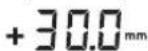
PactojaHnETo NomeFy poTaunOHATA
pAMHHa H CpeDnHnHaTaNHHja Ke CE
npKkae Ha ekpaHOT kako anCOyTHa
BpeHnOCT (BO [mm] nIn [inch]).
BnN I,NoecyBaHe Ha npKa3OT Ha
eHNHnIte",CTpaH 458.
Pa6oTeHe co nacepckn npHmHnK
PnMpeHBe BO HAdBopeWeH npocToH Ha rOenm
pactoJAHJa BO BHaTpeWeH npocToKopncTeTe Ro
IacepckNt PnEMNHk 3a IpoHaorabe Ha IacepckNt 3paK.
-Noctabete Ro NacepcknOt npemHHK Ha ToJ haHH WTo NacepcknOt 3paK Ke DoCTHHe Do npemHOTo NOte 26.
PaHno-Bpcka nomefy MePHnOT ypei n daeunHcknOt ynpabya/ba/nacepcknte nphemn
Bo cotojbaTaHa HcnpopaKa, HcnpaauHnTncepckn npemmHK LR 50 denyBa npeky 63KnuHa Bpcka Kaiko daeneHHNcKa KOHTpona Ha MePHnOTypeI.

-П рикадот PaДЗнeceрпявьа ja OЗнчуВа ФункNJATA HaДалЧИнСКОУпавыБеHa NaCEPCKNt ПпЕМNHK.
Ha mepHnOT ypeI MOKe Da My ce DoJeNt N NOBeKe Iacepckn npHemHnL R50.
-нcknyeTe ro mepHnoT ypei nIacepcknOt nphemnIK.
CTabeteToDONONHTENHNOIacepcknPiPemMHKBO CTAHuata3aONHebe/yyBaBe6.

-ПИТИСЕТе Ha konqueto 3a BkIyUyBaHbeNCKIyUyBaHbe 17.

-П рикадот Радно -Врcka 33kece nojabnja03haByaФункujataHa daNeuHcKOynpaByBaHe Ha nacepckhotnpemMHK.
-NoBtOpHn3BaTe rNacepckNt npHeMHNK OCTAHnUaTa 3a noJIHeHe/yuBaHe. NToTa, 3aJa rO BKnyUte MepHnOt ypeI, BO pOK oD 30 MNH. Mopa Ja rO npTINCHete KOnHTe 3a BknyyBaHe-NCKnyyBaHe 17.
HanomeHa:doKkyce doenat nobKe nacepckn nphemnHnHa eEne Mepeh ype, nocneHDo oOeHnot nacepckn npemHHK dnyBa kako daeneHHcKa KOHTpona. Dpyrnte Iacepckn npemHnIe Nybaat KaKo 6Hnn nphemnHn.
IOCTABKHTe HAOUHOCT NpHMepeHbHIN CnHAnHeHToH MoKe HNHNBHyANHO Da Ce NOdecaT3a CeKOJ nacepCKn PnEMHHK. DOKOKKY nacepCKN0rPnEMHHK Ce NKLyuCo FOHKunjata Ha daJeueHHCKy npabByBa, ce NckLyuBA H MepHNOrypeD. DOnONHHTeHNe TneacepCKn PnEMHHCu CE NKLyuBaAT 3ace6Ho.

ДokолуceпгнHe padNo-Bpckata, ДОПOLHITENHO KOH CINHaJIHOT ToH TpeNka npKa30T PaHNo-Bpcka 33.
CoToa ce cnHnHaIIm3npa DeKa npka3nte 3a npedynpyBaBe (Ha np. KpaXba,aHTN-Im3rauKn CnCTem, KaHbpaunja) Hema da ce npkaKATm MepHnOTypeHema nobEke da ce ynpabyBa DaneuHcKn.
HanomeHa:PeKHMOT Ha MmPyBaBe Ha MePepHOT ypeD MoKe 1a Ce BkNpyu Hn NckNpyu CaMo Co nPtHnCKaHe Ha KOnTuTo 3a peKHM Ha MmPyBaBe 21 Ha nacepckNt nphemHK co fyHKunJa Ha danueHHcKa KOHTpona.
IopeCyBaBe Ha CnTHaHNNOT ToH/tnacHOCTa
IOnuJaHa NaacepcknOt 3apKa Ha NoIeTo 3a npHem 26 ce npKakyBa CO CnHaeH ToH.
MoKe da 6nPaTe nOmeIy DBe jaUHH Ha INaCHOCT Nn Da rNCKJUYHTe CTHHaJIHNOT TOH.
CTaHapIHaTnOcTaBk npn Hcnpakatae [HOpMaJIEN CnHAnE ToH].

-ПипнckajTe Ha Konчeto CnHAnen ToH/tnaCHOCT 24,doJeka He ce nojaBn CaKaHaTa NoCTaBka.
Hema npnka3: CnHaJIHHOT ToE NcKnyeH

TnaceH CNrHaJIeH TOH
IocBaKaTa 3a CnHAnEn ToH/rrnacHOCT Ke Ce 3aUyBa npn NCKnyyBaBeTo.
N36epete ja nocTabkata Ha npka30 Ta cpeMnHa nnHjia
MoKeJa OndPeHnTe CO KOnKaBa ToUHcT Ke Ce npKakKe I03uJata Ha NaacepckHot 3paKHa npHeMHOTo None KaKo,BO cpeHnHa.
CTaHapdHaTata NoctabKa npn Hcnpakatae [ToHocT npn MepeHe,cpedHa/3mm"
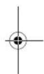


456 | MaKeDoHcKn
naobn nn jak notpec).3aToa, nped cekoj noeTOK ha pa6ota npoBepete ja kann6paunjata.
OTctanyBaHbata OJ OKony 20M mepha nnHnja ce 3emaat KaKo BaKHN MOKAT npu 100 M anconyTHO da H3HeCyBaAT DOKkpatHO NN YETPNPKpato OJ OTCTanyBaHeto npu 20 M.
BHejKTHemepaTPhHte pa3nKne HajroEmn BO6n3Ha Ha NIOOT, MEPHNOYpeTpe6a Da ce MOHTnpa cekoraH ha CTaTHB NOUYbajKn Od MEPHATAINHja oD 20 M. DOKOKy e BO3MOXHO, NOCTAByBaJTe RO MEPHNOYpeD BO cpeHNHata Ha pa6oTHATA NOBpHHa.
Iokky MepHnot ypeI ro npueekopmakcmanhoto OCTaYBaHe pnpnoDOny onnHaHTe MePHn cKlyCh, N3BpWte KaN6PpaBe (BnD ,KaN6PpaBe Ha MEPHnot ypeD, cTpaHa 456) nnn octabeTe ro MEPHnot ypeHa KOHTpona BO cepBncHata cnxy6ba Ha Bosch.
IpoBepka Ha ToUHocTa npn HnBEnHpAbe Bo xOpH3OHTaHa NoNox6a
3a npoBepkata notpe6ha e edha cno6DHa MepHa mHnJa o30 ma uBpcta noDnora nped sn. 3a cekoja X- H Y-ocka Mopa da n3BPWHe KOMnIeTHa MepHa noctanka.
-MoHTnpajTe ro MEPHOT ypeB DO XOpH3OHTaHa NoIox6bHa 30 m pactojahne OJ SIOOT HA CTaHB HIN NOCTaBeTe Ro Ha UbpctA, paMHa NOnIora. Bknyte r o MEPHOT ypeD.
-По завшиувае Нинвениразьето 03начete ja cpeината налaceрсnot spak Ha sNtot (Touka 1).
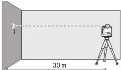
-CBpTe Ro MEPHnOT ype3a 180°,octabete ro da ce HNBEHnnpa nO3hauyete ja cpeHNHa Ha NacepcknT 3paK Ha sIIOt (TOkA II). BHMAbajte Ha ToA, TOkA Tla JNeKu ITO e MOxHO NOBepTKaIIHO Hd OHN. NoT OUKATA I.
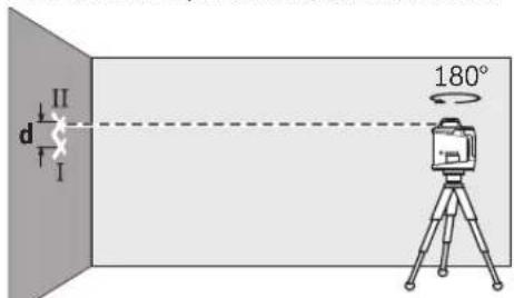
PaNkata dHa DBeTe O3Hauhen Tockn I n II Ha SNDOT TO DaBa FakTNKOTO OTcanyBaBe OD BcHnHa TA MePNOT ypeD 3a N3MepeHaTcOka.
Nobtopete ja mehpata noctanka 3a npyra ocka. Cbptetro mehpnoT ype npe nouetokot Ha mehpata noctanka 3a 90^
Ha Mepa HnHjia oJ 30 m MaKcMaJIHOTo Oo3BOeHOOTCTaYBaHe H3HECyBa:
30m× ± 0,1mm / m = ± 3,0mm
CnopeItoa,pa3nHKataD nometyTOUKHTe I NII npHcekojaO dBete MePHNIOCTANKcMeeJa H3HeCyBa HajMHOry 6 mm.
IpoBepKaHaToHocTa npn HnBemnpaBe BO BepTKKaHa noox6a (GRL 500 HV)
3a npOBepkata noTpe6ha e eHa cNo6oHa MePHa IINHJa Ha CBpCTa NoIgora nped 10 m BnCOK sN. Pnpucbpcte eeh Bucnyeu ha sNDOT.
-MoHTnpajTe ro MEPHnOT ypeB BO BepTknHa nonoK6a Ha eEN CTATNB HIN NOCTABeTe ro HA CBpCTa,paMHa NODIora. BknyuyeTe ro MEPHnOT ypeN OCTABeTe r da Ce HNBenipa.
-HacoueTe ro MEPHnotypeHaToJHaunHtOnacepcknot 3paKKe dojde BO KOHTAKTTOUHO cToPnHnot Kpaj Ha BnCyneot.Pa3nHKata d nomeFy nacepcknot 3paKn DOnHHOT Kpaj HbCynEoT Ro daBa OTcAnyBaHeTo Ha MEPHnotypeOdBepTKanata.
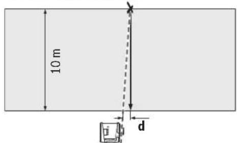
PnMepHaJIHHJaCoBcHNaO10mMaKChMaHIO D03BOHeHOOTCTaNYBaHe H3HecyBa:
10mx± 0,1mm / m = ± 1mm
CnopeiToa,pa3nIKkata d Cmee da H3HecyBa HajMhory 1 mm.
Kann6pnpaheHaMepHHOTypeI
CnEHNHTe INTEPBeHcM MoKe Da Ce BpUaT CaMo Od CtpaHa HA WKOJyBaH N KBaIINFmIupan NepcoHAn. Mopa da 6nDE No3Hata perynapHOCTa npn BPWeHe Ha npoBepKa Ha ToOHOCTA HIN KAIb6paunJa Ha MePHNOT ypeI.
H3BpTe ja kAn6pauijata Ha MEPnOtypei npeu3Ho HnOCTaBeTe ro MEPnOtypeHa KOHTpOa BO cepBcHATA cnyk6a Ha Bosch. Henpe3nHata KaIb6pauiJa BoNi Do nOrpeuHn pe3yntaH npi MepeIbeTo.
CTapTybajte ja KaHn6paunjata DOKOKy Mopa da ce N3Bpwn KaHn6paunja Ha MEPHNOTyped. UITOM MEPHNOTypee BO peKIM Ha KaHn6paunja, KaHn6paunjata Mopa da ce N3BpUn Do KpaJ, 3a Da He npOHane3at NorpeuHnpezITATN Od MepeHeTo.
HanomeHa:No KaHbpaunjata, npKa3nTe 3a KOHTpOHa Ha KaHbpaunjata Ke ce npKaKaxat Dpyn OTkako NOBtropHo Ke ce NojABn npuHnata 3a npEynpeyBaBeTo 3a KaHbpaunJa. 3a npOBepKaTATAOTpe6Ha e EHa CNo6oHa MePHa NInHJa oD 30 m Ha CBpTa nOJnora npEi sN.
Cekoraa KaIIb6papajte rI cHTe ockn (GRL 500 H: X- n Y- ocka; GRL 500 HV: X-, Y- n Z-ocka).


MaKeNoHcKn|457
Kannbpahe Ha X-ockaTa
-MoHTnpajTe ro MePHNOT ypeI BO xOpH3OHTaIIHa IIONoJ6a Ha eEN CTaINB 63 (ONPema).
- Noctabete ro ctaTbOT ha 30 m odaJeueHocT od SIO.
Pnka3oT ha rpaBnpaHa tCpHa ha X-ockata Ha MePHNO
yepd MOpA da 6nde BepTKaHNo NOCTABeH KOH SDOT.
BknyuheTe ro MePhHOTypeI.

-ПиHTCHeTe rH nCTOBpeMeHo KOnTuTo KaHbpaunja 25 n KOnTuTe 3a KocnHa 18okony2c.

O3hakata 3a KaHbpaunja Ha X-ockata Ke ce npkaKe Ha ekpaHoT.

3a Bpeme Ha aBToMaTcKTo HnBeHnpaHe TpEnKa PnPKa30 Ta npeynpeyBaHe 3a HnBeHnpaBe 37.
-Поуекатдодак He ce n3нвелпma МернOT ypeД.
-Co nOMoU Ha nacepcknOT pHemHnK npohajTe ja cpeiunHaTaNHHja HnpheceTe ja BncnHaTa X1"Ha cpeiunHaTaNHHja HA SNDOT.
-CBPTEToMepHNOype3a180°,6e3da ja npomeHHTE BHCNHaTtCTAHTBOT.
- Nooekajte DoeKa npka3ot 3a npdynpdyBahe 3a HBeHpaBe 37 He TpeNkA NOBKe H DoeKa He Ce HnHBenpa MepHOTypeI.
-Co IOMOu Ha IaIacepckHOT nPHEMHNK npOHajTe ja cpeINuHaTa IHHJa HnpeHeCeTe ja HOBaTa BcNHa, X2"Ha cpeINuHaTa IHHJa Ha SIOIT.
YtbpTe ja Touhata cpeHnHa NOMeFy cpeHnHHTe HHHn X1" nX2" n Ha Hea No3uohnpajTe ro Nacepcknot npemHnK co cpeHnHATA 03Haka 16.
-
PnHTNCHETe FO KOnyTe 3a KocNHa 18 HNN 20, DOneKa PnKHa3oT Ha CpeHnHaTa NnHJa 43 He 3acBETN KOHTNHynpaHO. PnBKnYueh CnHAnHe TOH Ce CnyuHa HenpeKnHAT ToH.
-
PnHTncHeTe ro KonTuTe KaHbpaunJa 25,3a da ja 3auyBaTe KaHbpaunJaTa.


O3HaKaTa 3a 3aBpuYBaHbHe Ha KaIb6paJata Ke ce npKakKe Ha ekpaHot.
-3a da ce hcknyn norgpehata kannbpaunjno 3aBpyBaBeTo Ha KANbpaunjata, Mopa da ja npOBepnte TOHcTa npHNBenpahe (BmN,Piobepka Ha ToCHoCTa pnp HNBENpaHe BO XOpH3OHTaHa nolok6a" CtpaHa 456). DOKONyOCTaNYBaBeTo cyeuTe neKn HAdBop od MaKcMaJHO Do3BoneHIne rpaHnU od ± 3,0 mm, OCTABeTo Ro MePHNOT ypeH Na KOHTpO BA cepBnCHata cnYkba Ha Bosch.
Kann6pnpaheHaY-ockata
-MoHTnpajte ro MePHNOTypeB BO xOpH3OHTanHa nOnox6a Ha eEN CTATNB 63 (onpema).
-Noctabete ro ctaHBOT ha 30 m odaaneuehoct od sNDOT. Pnka3OT Ha rpaBpHaHata cTpaHa HA Y-ockata Ha MePHNOT ypeMOPa da bHne BepTKKaHIO NOCTABEH KOH sNDOT.
-BknyeTe ro MeHHoT ypeI.

O3HaKaTa 3a KaHbpaunJa Ha Z-ocKaTa Ke ce PnKaKae Ha ekPaHOT.
-ImpaHmHETe rO cTaTnBOT HaToJ haunH wTo nacepckNt3paK Ke ce BkpcTyBa CO BeptnKaIHaTaNHHJa Ha SHdT.
3a Bpeme Ha aBTOMaTCKOTO HbEnIpaHBe TpENKa PnPKa30 3a NpeynpeyBaHe 3a HbEnIpaHBe 37.
-Поуекajtedoideka He ceи3HnBENIPA МернOTурд.

-Пинштete ro konyueto 3a KocnHa 18 HIN 20,doNeKa nacepckNt 3paK leXH ITo e MOxHO NopapaiHe HO Ha BepTKaJIHATA HInHja Ha SInOT.
-ДOKOLKY He ce nocturhe coBnafahbe, noBTOpeTe rnpetXOHNHTe YekOpn (H3pAMHeTe Ro CTaTHBOT, H3HBENPAjTe ro MePHNOT ypeI, H3pAMHete rNoacePCKNt 3paK co NOMoH Na KOnuHbTa 3a KocHa).


-ПиNTCHETe ro konTuTe kaHbpaunja 25,3a da ja 3auyBaTe kaHbpaunjata.
O3hakata 3a 3abpyBaHbHe Ha KaIb6paunjata Ke ce npKkaeHa ekpaHOT.
-3a da ce hcknyn norgpehata kann6paunja no 3abpybaheTo ha kann6paunjata, mopa da ja npOBepHte TOUHOCTa npH HBeNHPaHe (BnuD..PpOBepKa Ha ToUHOCTa npH HBeNHPaBe BO BepTtKanHa NOnOx6Ba" CtpHa 456). DOKONky OTcTanyBaHTeTo cyeuTE neXn HAdBOp od MaKcMAnHO Do3BOJeHIne TpaHnCi Od ± 1 mm, OCTabeTo MepHHOT ypeD, Ha KOHTpOla BO cepBnchata cnuykBa Ha Bosch.
Cobetn np pa6oTeheTo
MepHnotypee o npemeh co 6e3xuehen HHTeppejc. Tpe6a da cbeBHnMaBa Ha loKaJIHnTe onepaTHBn orpaHHyBaHa, HAp. Bo ABHOH mNbONHm.
3a 06eIkyBaHe, cekoraw KOpHcTeJe ca mo CpeHNHa NaCePckata NHHja. HnpHata Ha Nacepckata NHHja ce MeHyBa co OdaaneuYBaheTo.
IopecyBahe Ha npka30Ha eHHnHtHe
PactojaHneto Nomey potaunohata pAMHHa H cpeiHnHaTa IHHJa Ke ce npKaKe Ha ekpaHOT Bo [mm] mIn [inch: DeuMaJI/BO DpONK].
CtahapdHaTnocTabKa npH nCnpakatae [mm].

-ПИТСССЕНСТОВРЕМЕСHA KONЧETO ПОТаваье Ha TOTHOCT ПИЗ МЕРБETO 23и KONЧETO 3a KOCINHA 20doEka He ce nojabn CaKaHaTa NocTABka.

IocTabkata Ha eHINHnIte Ke ce 3auBya pIn NckNcyBaHaBeTo.
Iacepckn ouyna (onpeMa)
Nacepckte ouHa jaHnTnPaat OKnHaTa CBETnHa. Ha Toj NaHauHn npBeHTo CBETNo Ha Nacepot n3rIeJa nocBETno 3a OKOTO.
He rKOpHCTe NacepCKNTE OUYNA KAKO 3aHTTHO uHn. Nacepcknte Ouyna Cnykat 3a noobpo npeno3HaBahe Ha NacepCKNt 3paK, Ho He 3aHTyBaat od NacepckTO 3pauebe.
He HN KOPNCTe NacepCKNe Oouna KaO Oouna 3a coHue nn NaK Bo c0o6paKaJot. NacepCKNe Oouna He daBaat cenocHa UV-3aunTa n ro HaMaIyBaat npeno3HaBaHbTo Ha 60n.
Pa6oTeHe co cTaTHB (onpeMa)
MepHnOT ypeI paONar a co 5/8"-npHpaT 3a cTaNb 3a xOpH3OHTaJIeN peKIM Ha eEN cTaNb. IocTaBete rO mepHnOT ypeI c npHpaT0 3a cTaNb Ha 5/8"-HaBOJ Ha cTaNBOT n 3aWpaPefe ro co wpaPOT 3a pIKCNpaHe HA cTaNBOT. Kaj cTaNBOT 63 co MEPHa cKaIa Ha H3BNeKyBaBe MoKe dIpeKTHo Da rnoJeCte OTeCTanyBaBeTo NO BNCnHa.
Pa6oTeHe co sHdEn dpxkaH eHNHua 3a H3paMHyBaHe (onpema)
MepHnOT ypeI MOJE Da ro MoHTnpaTe Ha sIneH dpJxau co
edHHua 3a n3pamHyBaBe 59. 3auppaTe Ro 5/8"-uPapot
62 Ha sIneH dPkay Bo npiaTOT 3a cTaN H Ma MEPnOt ypeI.
MoTHaHa sND: MoTHaKaTa Ha sNc Ce npenopayBa Hanp.
npaBoTn, KOc Ce HAD BHCnHATA Ha N3BNeKyBaBe Ha
CTaNTB, ININ pPi NaPbOteHe Ha HeCTaBnHa NoDnOra N 63
CTaNB. PnHToa, pNtBPCTe Ro SInHnO T dPkau 59 co
MOHTpAH MepeH ypeI wTO e MOXHO NOBEPTKAnHO Ha sNDOT.
3a MoTHaHa sNDOT, sNDeH dPkay 59 Moe Da rO
npiUbpcTHe Co IwA pa 3a npinBpcTyBaHe 60 Ha neTBA Od
MaKc. 8 MM uipnHa INI da Ro 3akayHe Ha DBe Kynk.
MoTHaHa h CTaN:B: SInHnOT dPkay 59 Moe Da rO
3aWpaDnTE H CO npiaTat 3a CTaN H Ra3dHata CtpHa Od
CTaNBT. Oba 3auBpcTyBaBe OC6eHo Ce npenopayBa npi
pa6oTn, KaDe potaHNOHO HNo BO tpe6a Da ce n3pamHn Ha
pepepeHTHa nnHja.
Co nomow Ha eHHnUata Ha H3paMHyBaHe, MoKe Da rO nOMeCTHtMe MepHNOtypeBepTknAHO (pN pMOHTaHa Ha sI) Odn. xOpH3oHTaHNO(pN MOHTaHa HA cTaN) Ha NOte oD OKony 16 cm. PnHToa, ONA6aBeTe ro wpaFOT 61 Ha eHHuata 3a H3paMHyBaHe, NOMeCTeTe ro MepHNoTpeD Bo cakaHaTa No3uJa, I NOBtPOH 3aTeHrTe Ro WpaFOT 61.


MaKeIoHcKn | 459
Pa6oTebe co MepeHa IeTbA (Onpema) (BmHn CInka H)
3a KOHtpona Ha HepaMHHH Hn 3a HaHeCyBaBe Ha KocHH Ce npenopauyBa KopncTehe Ha MepHa IetBa 55 3aeHNO co IacepckNt PnpemHNK.
Ha MepHata NtBa 55 rope nHa HaneceHo peNaTHBHa MepHa ckana (± 50cm) .Hej3nHata HyNTa BnCnHa MoKe da ja h36epeTe dony Ha n3ne3oT. Ha ToJ haunn DnpeKTHo ce OHTUYbaaT OTcanyBaHbTaOd 3aJaDeHATA BnCnHa.
PpHmepn 3a pa60ta
IpoBepka Ha dna6oHHata Ha rpaedxHHTe jAMN (BnDn CnKa I)
IIOCTaBeTe Ro MEPHnOT ypeHa CTaBnHa nOtnora mMOHTnpajTe Ro Ha CTaTb63.
-Pa6oTeHe co CTaTHB: H3pAMHete rO nacepcknOT 3paK Ha cakHaTbA BcHnHa. IpeHecTe ja Odn. npOBepeTe ja BcHnHa T ha CEHhTo MecTO.
Pa6oTeHe 6e3 cTaNb: IpoHajTeJe ja BnCHNcKa pa3nka nOmeFy nacepcknoT 3paK nBnCHnHa ta pepepeHTHa ToUka. IpeHecete ja oDn. npOBepeJa n3MepeHaTa BnCHNcKa pa3nka Ha ceHHO TMeTO.
PnMpeHBe Ha roIemPiactoJAHja, MepHnOt ypeTpe6a da ro NoCTAByBate cekoraiu Bo cpeHHata Ha pa6oTHata IOBpHHHa Nda Ro NOCTaBITE Ha CTaHB, 3a Da Ro HAMaHTe BInjahnE To Ha npeKHTe.
-Пи рабote He Ha HecnrypeH NOI,MOHTnpajTe rO MEPHNOtypeHa cTATNB 63.BHHMaBajTe -aHTN-JIN3raKNOT CNTeMe aKTMBpAn,3a Da N36erHete NOrpeuHm MepBa npiDBrHexHe Ha NoDT INI NOTpcEn Ha MEPHNOtype.
OttpaHyBaBe Ha npeyKn
IpeuKoCo KoO 3a rpeWka
KoDor 3a rpeuKa ke ce npkaKe Ha ekpaHOT.
Laser Radiation Class 2 do not stare into beam
IEC60825-1:2014 <1mW,635nm
Ako tekst tablice sa opomenom ici na Vasem jeziku, onda prelepite ga pre prvog pustanja u rad sa isporucenom nalepnicom na jeziku Vase zemplje.

Ne usmeravajte laserski zrak na osobe ili zivotinje i sami ne gledajte u direktan ili reflektuji ci laserski zrak. Na taj nacin mozte dazaslepite lica, prouzrokujete nezgode ili da ostetite oci.
Ako lasersko zracenje dode u oko, morate svesno da zatvorite oki i da glavu odmah okrenete od zraka.
Nemoje da vrsite promene na laserskoj opremi.
Ne koristite laserske naoCare za posmatranje kao zastitne naoCare. Laserske naoCare za posmatranje sluze za bolje prepoznavanje laserskog zraka, one ne stite od laserskog zracenja.
Ne upotreblavajte laserske naocare za posmatranje kao naocare za sunce ili u putnom saobracaju. Laserske naocare za posmatranje ne pruzaju punu UV zastitu i smanjuju opazanje boja.
Neka Vam merni alat popravlja strucno osoblje i samo sa originalnim rezervnim delovima. Time se obezbedjuje, da sigurnost ernog alata ostaje sacuvana.
Ne dopu staje deci korijscenje ernog alata sa laserom bez nadzora. Oni bi mogli nenamernozaslepiti osoblje.
Ne radite sa mernim alatom u okolini gde postoji opasnost od eksplozija, u kojo se nalaze zapaljive tecnosti, gasovi ili prasine. U mernom alatu se mogu proizvesti varnice, koje bi zapalite prasinu ili isparenja.

Zastitite merni alat od toplate, na primer i od trajnog suncevog zracenja, vatre, vode i vlage. Postoji opasnost od eksplozija.
Kod pogresne primene moze tecnost da izadje iz akku. Izbegavaje kontakt sa njom. Kod slucajnog kontakta isperite sa vodom. Ako tecnost dospe u oci, iskoristite i dodatnu lekarsku pomoc. Tecnost baterije koja izlazi maybe voditi nadrazajima koze ili opekotinama.
Kodostećenja inestrucne upotrebe akumulatora mogu izlaziti pare. Dovedite svezdzuh potrazite lekara akododje do tegoba. Para moze nadroziti disajne puteve.
Punite akumulatorismo sa isporučinem uredjajem za punjenje. Za uredjaj za punjenje koji je pogodan za odredjenu vrstu akumulatora, postoji opasnost ako se upotrebljava sa drugim akumulatorima.

Ne donosite merni alat i lasersku tablicu sa ciljem u blizin pejsmejkera. Magneti mernog alata i laserska tablica sa ciljem proizvode polje, koje moze ošetiti funkcjiu pejsmejkera.
Drzite merni alat i lasersku tablicu sa ciljem dalje od mangetnih nosa podataka imegnetno osetljivih uredjaja.Delovanjemagneta ernog alata i laserske tablice sa ciljem moze doci do nepovratnih gubitaka podataka.
Akku-aparat za punjenje