GOF 1300 CE Professional - Milling machine BOSCH - Free user manual and instructions
Find the device manual for free GOF 1300 CE Professional BOSCH in PDF.
| Product type | Plunge router (router) |
| Brand | Bosch |
| Model | GOF 1300 CE Professional |
| Rated power | 1300 W |
| No-load speed | 12000 - 24000 rpm |
| Speed presetting | Yes (6-position dial) |
| Constant Electronic | Yes (maintains speed under load) |
| Tool holder (collet) | 6 - 12.7 mm |
| Plunge stroke | 58 mm |
| Weight (according to EPTA) | 4.8 kg |
| Protection class | II (double insulation) |
| Rated voltage | 230 V |
| Dust extraction connection | Yes (Ø 35 mm) |
| Soft start | Yes |
| Spindle lock | Yes (for bit change) |
| Parallel guide | Included, finely adjustable |
| Circle cutter | Optional accessory for circles |
| Copy ring | Accessory for copying templates |
| Included accessories | Chip deflector, depth stop, dust extraction adapter, 24 mm open-end wrench |
| Maintenance | Regular cleaning of ventilation slots, external extraction recommended |
| Repairability | Bosch after-sales service, spare parts available |
| Application areas | Wood, plastics, lightweight building materials, non-ferrous metals (with reduced speed) |
Frequently Asked Questions - GOF 1300 CE Professional BOSCH
User questions about GOF 1300 CE Professional BOSCH
0 question about this device. Answer the ones you know or ask your own.
Ask a new question about this device
Download the instructions for your Milling machine in PDF format for free! Find your manual GOF 1300 CE Professional - BOSCH and take your electronic device back in hand. On this page are published all the documents necessary for the use of your device. GOF 1300 CE Professional by BOSCH.
USER MANUAL GOF 1300 CE Professional BOSCH
OHJDKOU-3252-014FmPage 1 Wednesday,November 23,2011 9:49AM
Robert Bosch GmbH
Power Tools Division
bgOpHmHnHnHnHnHnHnHnHnHnHnHnHnHnHnHnHnHnHnHnHnHnHnHnHnHnHnHnHnHnHnHnHnHnHnHnHnHnHnHnHnHnHnHnHnHnHnHnHnHnHnH
srOriginalno upstvo za rad
sizirnahayocla
hrOriginaline upute za rad
etugapurane kasutusjuhend
Minstrukojas original
Konghail Insurkla
ar
1

N
Deutsch 7
Deutsch
Sicherheitshinweise
Dr. Egbert Schneider Senior Vice President Engineering
Dr. Eckerhard Strötgen
Engineering Director
PT/ESI
Paa /nau
Robert Bosch GmbH, Power Tools Division D-70745 Leinfelden-Echterdingen 26.10.2011
Montage
General Power Tool SafetyWarnings
WARNING
Read all safety warnings and all instructions. Failure to follow the warn
and instructions may result in electric shock, fire and/or serious injury.
Save all warnings and instructions for future reference.
The term "power tool" in the warnings refers to your mains-operated (corded) power tool or battery-operated (cordless) power tool.
Work area safety
- Keep work area clean and well lit. Cluttered or dark areas invite accidents.
Do not operate power tools in explosive atmospheres, such as in the presence of flammable liquids, gases or dust. Power tools create sparks which may ignite the dust or fumes. - Keep children and bystanders away while operating a power tool. Distractions can cause you to lose control.
Electrical safety
Power tool plugs must match the outlet. Never modify the plug in any way. Do not use any adapter plugs with earthed (grounded) power tools. Unmodified plugs and matching outlets will reduce risk of electric shock.
- Avoid body contact with earthed or grounded surfaces, such as pipes, radiators, ranges and refrigerators.
There is an increased risk of electric shock if your body is earthed or grounded.
Do not expose power tools to rain or wet conditions. Water entering a power tool will increase the risk of electric shock.
Do not abuse the cord. Never use the cord for carrying, pulling or unplugging the power tool. Keep cord away from heat, oil, sharp edges and moving parts. Damaged or entangled cords increase the risk of electric shock.
When operating a power tool outdoors, use an extension cord suitable for outdoor use. Use of a cord suitable for outdoor use reduces the risk of electric shock.
If operating a power tool in a damp location is unavoidable, use a residual current device (RCD) protected supply. Use of an RCD reduces the risk of electric shock.
Personal safety
Stay alert, watch what you are doing and use common sense when operating a power tool. Do not use a power tool while you are tired or under the influence of drugs, alcohol or medication. A moment of inattention while operating power tools may result in serious personal injury.
Use personal protective equipment. Always wear eye protection. Protective equipment such as dust mask, non-skid safety shoes, hard hat, or hearing protection used for appropriate conditions will reduce personal injuries.
Prevent unintentional starting. Ensure the switch is in the off-position before connecting to power source and/or battery pack, picking up or carrying the tool.
Carrying power tools with your finger on the switch or energising power tools that have the switch on invites accidents.
Remove any adjusting key or wrench before turning the power tool on. A wrench or a key left attached to a rotating part of the power tool may result in personal injury.
Do not overreach. Keep proper footing and balance at all times. This enables better control of the power tool in unexpected situations.
English | 15
Dress properly. Do not wear loose clothing or jewellery. Keep your hair, clothing and gloves away from moving parts. Loose clothes, jewellery or long hair can be caught in moving parts.
If devices are provided for the connection of dust extraction and collection facilities, ensure these are connected and properly used. Use of dust collection can reduce dust-related hazards.
Power tool use and care
Do not force the power tool. Use the correct power tool for your application. The correct power tool will do the job better and safer at the rate for which it was designed.
Do not use the power tool if the switch does not turn it on and off. Any power tool that cannot be controlled with the switch is dangerous and must be repaired.
- Disconnect the plug from the power source and/or the battery pack from the power tool before making any adjustments, changing accessories, or storing power tools. Such preventive safety measures reduce the risk of starting the power tool accidentally.
- Store idle power tools out of the reach of children and do not allow persons unfamiliar with the power tool or these instructions to operate the power tool. Power tools are dangerous in the hands of untrained users.
- Maintain power tools. Check for misalignment or binding of moving parts, breakage of parts and any other condition that may affect the power tool's operation. If damaged, have the power tool repaired before use. Many accidents are caused by poorly maintained power tools.
- Keep cutting tools sharp and clean. Properly maintained cutting tools with sharp cutting edges are less likely to bind and are easier to control.
Use the power tool, accessories and tool bits etc. in accordance with these instructions, taking into account the working conditions and the work to be performed. Use of the power tool for operations different from those intended could result in a hazardous situation.
Service
Have your power tool serviced by a qualified repair person using only identical replacement parts. This will ensure that the safety of the power tool is maintained.
SafetyWarnings for Routers
Hold power tool by insulated gripping surfaces, because the cutter may contact its own cord. Cutting a "live" wire may make exposed metal parts of the power tool "live" and shock the operator.
Use clamps or another practical way to secure and support the workpiece to a stable platform. Holding the work by your hand or against the body leaves it unstable and may lead to loss of control.
The allowable speed of the router bit must be at least as high as the maximum speed listed on the power tool. Accessories that rotate faster than permitted can be destroyed.
Router bits or other accessories must fit exactly in the tool holder (collet) of your machine. Routing bits that do not fit precisely in the tool holder of the machine rotate irregularly, vibrate heavily and can lead to loss of control.
Apply the machine to the workpiece only when switched on. Otherwise there is danger of kickback when the cutting tool jams in the workpiece.
- Keep your hands away from the routing area and the router bit. Hold the auxiliary handle or the motor housing with your second hand. When both hands hold the machine, they cannot be injured by the router bit.
- Never cut over metal objects, nails or screws. The router bit can become damaged and lead to increased vibrations.
Use suitable detectors to determine if utility lines are hidden in the work area or call the local utility company for assistance. Contact with electric lines can lead to fire and electric shock. Damaging a gas line can lead to explosion. Penetrating a water line causes property damage or may cause an electric shock.
Do not use blunt or damaged router bits. Blunt or damaged router bits cause increased friction, can become jammed and lead to imbalance.
- When working with the machine, always hold it firmly with both hands and provide for a secure stance. The power tool is guided more secure with both hands.
Always wait until the machine has come to a complete stop before placing it down. The tool insert can jam and lead to loss of control over the power tool.
Products sold in GB only: Your product is fitted with an BS 1363/A approved electric plug with internal fuse (ASTA approved to BS 1362). If the plug is not suitable for your socket outlets, it should be cut off and an appropriate plug fitted in its place by an authorised customer service agent. The replacement plug should have the same fuse rating as the original plug. The severed plug must be disposed of to avoid a possible shock hazard and should never be inserted into a mains socket elsewhere.
Products sold in AUS and NZ only: Use a residual current device (RCD) with a rated residual current of 30mA or less.
Product Description and Specifications

Read all safety warnings and all instructions. Failure to follow the warnings and instructions may result in electric shock, fire and/or serious injury.
While reading the operating instructions, unfold the graphics page for the machine and leave it open.
16|English
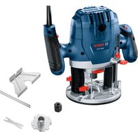
Intended Use
The machine is intended for routing grooves, edges, profiles and elongated holes as well as for copy routing in wood, plastic and light building materials, while resting firmly on the workpiece.
With reduced speed and with appropriate routing bits, nonferrous alloys can also be machined.
Product Features
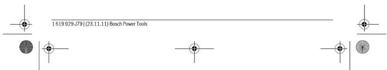
The numbering of the product features refers to the illustration of the machine on the graphics page.
1 Right handle (insulated gripping surface)
2 Lock-on button for On/Off switch
3 Thumbwheel for speed preselection
4 Spindle lock lever
5 Wing bolt for guide rods of parallel guide (2x)^
6 Chip shield
7 Router bit
8 Seat for parallel guide rods
9 Guide plate
10 Step buffer
11 Adjusting screws for step buffer
12 Base plate
13 Dust boot
14 Wing bolt for depth stop adjustment
15 Depth stop
16 Slide with index mark
17 Left handle (insulated gripping surface)
18 Scale for depth-of-cut
19 Scale for depth-of-cut fine adjustment
20 Adjustment knob for depth-of-cut fine adjustment
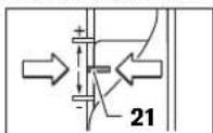
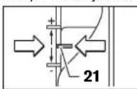
21 Mark for zeroing
22 Release lever
23 Tightening nut with collet
24 On/Off switch
25 Open-end spanner, size 24 mm
26 Extraction hose (0 35 mm)
27 Extraction adapter
28 Knurled screw for extraction adapter (2x)^
29 Parallel guide
30 Guide rod for parallel guide (2x)^
31 Wing bolt for fine adjustment of parallel guide (2x)^
32 Wing bolt for coarse adjustment of parallel guide (2x)^
33 Fine-adjustment knob for parallel guide
34 Adjustable edge guide for parallel guide
35 Extraction adapter for parallel guide
36 Router compass/guide-rail adapter
37 Router compass handle
38 Wing bolt for coarse adjustment of router compass (2x)
39 Wing bolt for fine adjustment of router compass (1x)
40 Fine-adjustment knob for router compass
41 Centring screw for compass stop
42 Base spacer (included in the "router compass" set)
43 Guide rail
44 SDS guide-bushing adapter
45 Fastening screw for guide bushing adapter (2x)
46 Release lever for guide bushing adapter
47 Guide bushing
48 Pan head screw for guide plate
49 Countersunk head screw for guide plate
50 Centring pin
Accessories shown or described are not part of the standard delivery scope of the product. A complete overview of accessories can be found in our accessories program.
Technical Data
| Plunge router GOF 900 CE | |||
| Professional | GOF 1300 CE Professional | ||
| Article number 0 601 614 6.. 0 601 613 6.. | |||
| Rated power input | W | 9 | 0 |
| No-load speed | \( min^{-1} \) | 12000 - 24000 | 12000 - 24000 |
| Speed preselection | ● | ● | |
| Constant electronic control | ● | ● | |
| Connection for dust extraction | ● | ● | |
| Tool holder | mm | 6 - 8 | 6 - 12.7 |
| inch | 1/4 | 1/4 - 1/2 | |
| Plunge depth | mm 50 58 | ||
| Weight according to EPTA-Procedure 01/2003 | kg 3.5 4.8 | ||
| Protection class | ☐/II /II | ☐ | |
| The values given are valid for a nominal voltage [U] of 230 V. For different voltages and models for specific countries, these values can vary. Please observe the article number on the type plate of your machine. The trade names of the individual machines may vary. | |||
English|17
Noise/Vibration Information
Measured sound values determined according to EN 60745.
Typically the A-weighted noise levels of the product are: Sound pressure level 89 dB(A); Sound power level 100 dB(A). Uncertainty K = 3 dB.
Wear hearing protection!
Vibration total values a (triax vector sum) and uncertainty K determined according to EN 60745:
a_h = 5.5m / s,K = 2.5m / s^2
The vibration emission level given in this information sheet has been measured in accordance with a standardised test given in EN 60745 and may be used to compare one tool with another. It may be used for a preliminary assessment of exposure.
The declared vibration emission level represents the main applications of the tool. However if the tool is used for different applications, with different accessories or poorly maintained, the vibration emission may differ. This may significantly increase the exposure level over the total working period.
An estimation of the level of exposure to vibration should also take into account the times when the tool is switched off or when it is running but not actually doing the job. This may significantly reduce the exposure level over the total working period.
Identify additional safety measures to protect the operator from the effects of vibration such as: maintain the tool and the accessories, keep hands warm, organise work patterns.
Declaration of Conformity C
We declare under our sole responsibility that the product described under "Technical Data" is in conformity with the following standards or standardization documents: EN 60745 according to the provisions of the directives 2011/65/EU, 2004/108/EC, 2006/42/EC.
Technical file (2006/42/EC) at:
Robert Bosch GmbH, PT/ETM9
D-70745 Leinfelden-Echter
Dr. Egbert Schneider
Senior Vice President
Engineering
Dr. Eckerhard Strötgen
Engineering Director
PT/ESI

Robert Bosch GmbH, Power Tools Division
D-70745 Leinfelden-Echterdingen
26.10.2011
Assembly
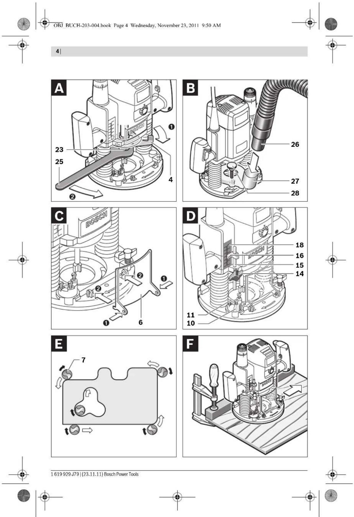
Inserting a Router Bit (see figure A)
Before any work on the machine itself, pull the mains plug.
It is recommended to wear protective gloves when inserting or replacing router bits.
Depending on the application, router bits are available in the most different designs and qualities.
Router bits made of high speed steel (HSS) are suitable for the machining of soft materials, e. g. softwood and plastic.
Carbide tipped router bits (HM) are particularly suitable for hard and abrasive materials, e. g. hardwood and aluminium.
Original router bits from the extensive Bosch accessories program are available at your specialist shop.
Only use clean router bits that are in perfect condition.
-Fold the chip shield 6 down.
Push the spindle lock lever 4 in clockwise direction and hold it in this position (O). If required, turn the motor spindle by hand until it is locked.
-Loosen the tightening nut 23 with the open-end spanner 25 (size 24mm by turning in anticlockwise direction ()
- Insert the router bit into the collet. The shank of the router bit must be immersed at least 20mm into the collet.
- Tighten the tightening nut 23 with the open-end spanner 25 (size 24mm ) by turning in clockwise direction. Release the spindle lock lever 4.
-Fold the chip shield 6 up again.
Do not insert a router bit with a diameter larger than 50mm when the guide bushing is not mounted. Such router bits do not fit through the base plate.
- Do not tighten the tightening nut of the collet without a router bit inserted. Otherwise the collet can be damaged.
Dust/Chip Extraction (see figure B)
Dusts from materials such as lead-containing coatings, some wood types, minerals and metal can be harmful to one's health. Touching or breathing-in the dusts can cause allergic reactions and/or lead to respiratory infections of the user or bystanders.
Certain dusts, such as oak or beech dust, are considered as carcinogenic, especially in connection with wood-treatment additives (chromate, wood preservative). Materials containing asbestos may only be worked by specialists.
- As far as possible, use a dust extraction system suitable for the material.
- Provide for good ventilation of the working place.
- It is recommended to wear a P2 filter-class respirator.
Observe the relevant regulations in your country for the materials to be worked.
Prevent dust accumulation at the workplace. Dusts can easily ignite.
Mounting the Extraction Adapter
The extraction adapter 27 can be mounted with the hose connection to the front or to the rear. When the guide bushing adapter 44 is mounted, it is possible that the guide bushing adapter must be turned by 180^ so that the extraction adapter 27 does not touch the release lever 46. When mounting with the hose connection in front, the chip shield 6 must be removed first. Fasten the extraction adapter 27 with the 2 knurled screws 28 to the base plate 12.
Connecting the Dust Extraction
Insert an extraction hose (0 35 mm) 26 (accessory) into the mounted extraction adapter. Connect the extraction hose 26 to a vacuum cleaner (accessory).
18|English
The machine can be plugged directly into the receptacle of a Bosch all-purpose vacuum cleaner with remote starting control. The vacuum cleaner starts automatically when the machine is switched on.
The vacuum cleaner must be suitable for the material being worked.
When vacuuming dry dust that is especially detrimental to health or carcinogenic, use a special vacuum cleaner.
Mounting the Chip Shield (see figure C)
Insert the chip shield 6 from the front into the guide in such a manner that it engages. To remove the chip shield, grasp it by the sides and pull it off toward the front.
Operation
Starting Operation
Observe correct mains voltage! The voltage of the power source must agree with the voltage specified on the nameplate of the machine. Power tools marked with 230V can also be operated with 220V .
Preselecting the Speed
The required speed can be preselected with the thumbwheel 3 (also while running).
1-2 low speed
3-4 medium speed
5-6 high speed
The values shown in the chart are standard values. The necessary speed depends on the material and the operating conditions, and can be determined by practical testing.
| Material Router bit | diameter (mm) | Thumb- wheel 3 |
| Hardwood (Beech) | 4 - 10 | 5 - 6 |
| 12 - 20 | 3 - 4 | |
| 22 - 40 | 1 - 2 | |
| Softwood (Pine) | 4 - 10 | 5 - 6 |
| 12 - 20 | 3 - 6 | |
| 22 - 40 | 1 - 3 | |
| Particle Board | 4 - 10 | 3 - 6 |
| 12 - 20 | 2 - 4 | |
| 22 - 40 | 1 - 3 | |
| Plastics 4 - 15 | 2 - 3 | |
| 16 - 40 | 1 - 2 | |
| Aluminium | 4 - 15 | 1 - 2 |
| 16 - 40 | 1 |
After longer periods of working at low speed, allow the machine to cool down by running it for approx. 3 minutes at maximum speed with no load.
Switching On and Off
Adjust the depth-of-cut before switching on or off; see Section "Adjusting the Depth-of-cut".
To start the machine, press the On/Off switch 24 and keep it pressed.
To lock the pressed On/Off switch 24, press the lock-on button 2.
To switch off the machine, release the On/Off switch 24 or when it is locked with the lock-on button 2, briefly press the On/Off switch 24 and then release it.
Constant Electronic Control
Constant electronic control holds the speed constant at no-load and under load, and ensures uniform working performance.
Soft Starting
The electronic soft starting feature limits the torque upon switching on and increases the working life of the motor.
Adjusting the Depth-of-cut (see figure D)
The adjustment of the depth-of-cut may only be carried out when the router is switched off.
For coarse adjustment of the depth-of-cut, proceed as follows:
- Place the machine with the router bit mounted on the workpiece to be machined.
- Set the fine-adjustment path to the centre position with the adjustment knob 20. For this, turn the adjustment knob 20 until the marks 21 match as shown in the figure. Afterwards, set the scale 19 to "0".
- Set the step buffer 10 to the lowest position; the step buffer engages noticeably.
- Loosen the wing bolt for the depth stop 14 so that the depth stop 15 can be moved freely.
Push the release lever 22 downward and slowly lower the plunge router until the router bit 7 touches the surface of the workpiece. Let go of the release lever 22 again to lock this plunging depth.
Push the depth stop 15 downward until it rests on the step buffer 10. Set the slide with the index mark 16 to the "0" position on the scale for the depth-of-cut adjustment 18. - Set the depth stop 15 to the required depth-of-cut and tighten the wing bolt for the depth stop 14. Pay attention not to misadjust the slide with the index mark 16 again.
Push the release lever 22 and guide the plunge router to the uppermost position.
For deep cuts, it is recommended to carry out several cuts, each with little material removal. By using the step buffer 10, the cutting process can be divided into several steps. For this, adjust the desired depth-of-cut with the lowest step of the step buffer and select the higher steps first for the initial cuts. The clearance of the steps can be changed by screwing the adjusting screws 11 further in or out.
After a trial cut, the depth-of-cut can be set exactly to the desired measure by turning the adjustment knob 20: turn in clockwise direction to increase the cutting depth and in anticlockwise direction to decrease the cutting depth. The scale 19 can be used for guidance. One full turn corresponds with a
setting range of 2.0 mm; a graduation mark on the top edge of the scale 19 corresponds with a 0.1 mm change of the setting range. The maximum setting range is ± 8 mm.
Example: The desired depth-of-cut is to be 10.0mm ; the trial cut resulted in a cutting depth of 9.6mm .
Lift up the router and place e. g. a piece of scrap wood under the guide plate 9 so that the router bit 7 cannot touch the workpiece when lowering it. Push the release lever 22 down and slowly lower the plunge router until the depth stop 15 faces on the step buffer 10.
Turn the scale 19 to "0" and loosen wing bolt 14.
Turn the adjustment knob 20 by 0.4mm / 4 graduation marks (difference from set to actual value) in clockwise direction and tighten the wing bolt 14.
- Check the selected depth-of-cut by carrying out another trial cut.
After adjusting the depth-of-cut, do not change the position of the slide 16 on the depth stop 15 any more, so that the actual cutting depth can be read on the scale 18.
Working Advice
Protect router bits against shock and impact.
Direction of Feed and Routing Process (see figure E)
The routing process must always be carried out against the rotation direction of the router bit 7 (up-cutting motion). When routing in the direction with the rotation of the router (down-cutting), the machine can break loose, eliminating control by the user.
- Adjust the required depth-of-cut; see Section "Adjusting the Depth-of-cut".
- Place the machine with the router bit mounted on the workpiece to be machined and switch the power tool on.
Push the release lever 22 down and slowly lower the plunge router until the adjusted depth-of-cut is reached. Let go of the release lever 22 again to lock this cutting depth. - Carry out the routing process applying uniform feed.
- After finishing the cutting process, guide the plunge router upward again to the uppermost position.
- Switch the power tool off.
Routing with Auxiliary Guide (see figure F)
For working large workpieces, e.g. when routing grooves, a board or wood strip can be fastened to the workpiece as an auxiliary guide alongside which the router can be guided. Guide the router with the flattened side of the guide plate along the auxiliary guide.
Shaping or Molding Applications
For shaping or molding applications without the use of a parallel guide, the router bit must be equipped with a pilot or a ball bearing.
- Guide the switched on power tool from the side toward the workpiece until the pilot or the ball bearing of the router bit faces against the workpiece edge to be machined.
Guide the power tool alongside the workpiece edge with both hands, paying attention that the router is positioned rectangular. Too much pressure can damage the edge of the workpiece.
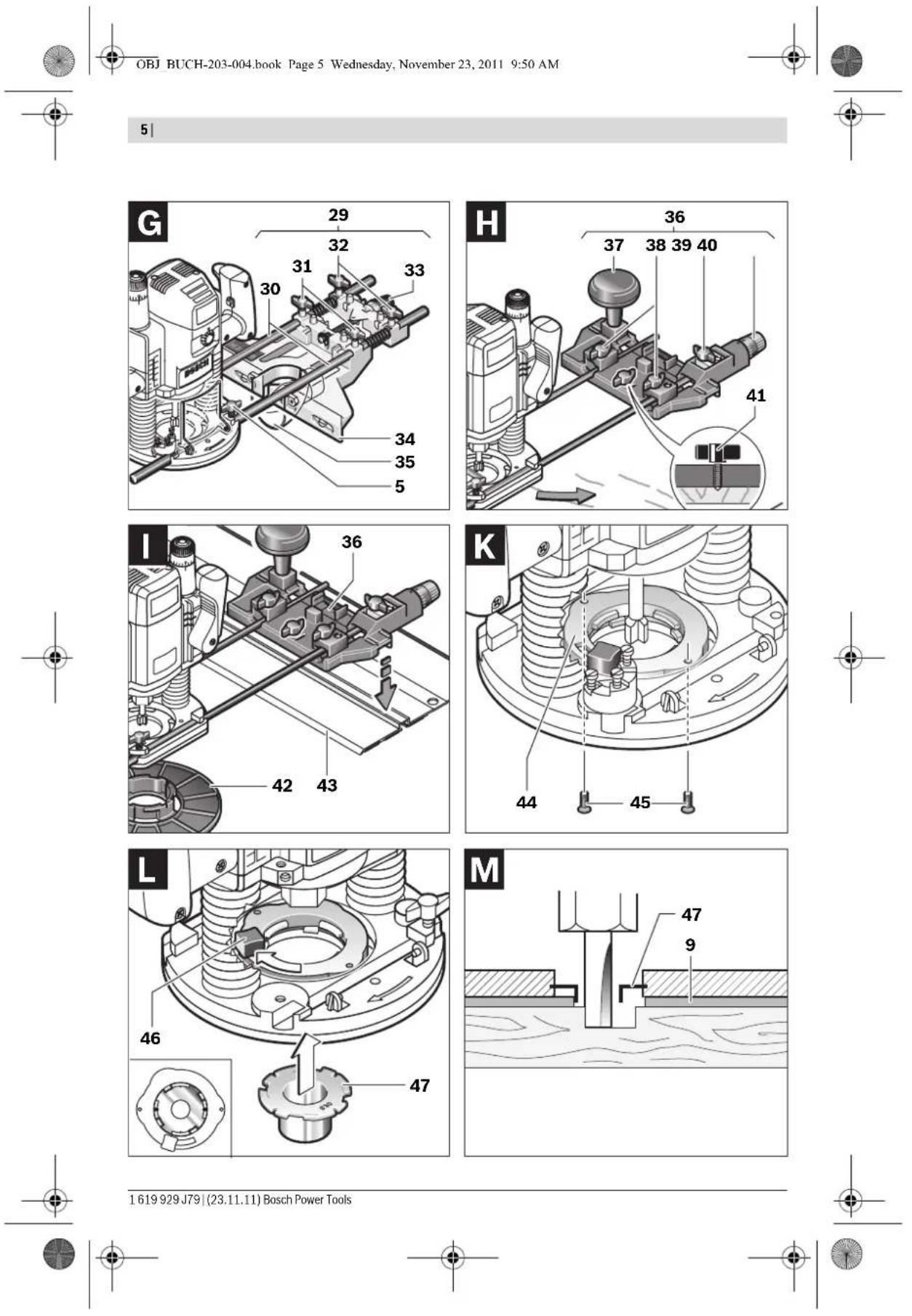
Routing with Parallel Guide (see figure G)
Slide the parallel guide 29 with the guide rods 30 into the base plate 12 and tighten as required with the wing bolts 5. Additionally, the parallel guide can be adjusted lengthwise with the wing bolts 31 and 32.
Fine adjustment of the length is possible with the fine-adjustment knob 33 after loosening both wing bolts 31. One revolution corresponds with a setting range of 2.0mm . One graduation mark on the fine-adjustment knob 33 changes the setting range by 0.1mm .
The effective contact surface of the parallel guide can be adjusted with the edge guide 34.
Guide the switched on power tool with uniform feed and lateral pressure on the parallel guide alongside the workpiece edge.
When routing with the parallel guide 29, the dust/chip extraction should take place via the special extraction adapter for the parallel guide 35. The extraction adapter 27 can remain mounted.
Routing with the Router Compass (see figure H)
The router compass/guide-rail adapter 36 can be used for circular routing jobs. Mount the router compass as shown in the figure.
Screw the centring screw 41 into the thread on the router compass. Insert the point of the centring screw into the centre of the circular arc to be routed, paying attention that point of the screw engages into the workpiece surface.
Coarsely adjust the required radius by moving the router compass and tighten the wing bolts 38 and 39.
The length can be fine adjusted with the fine-adjustment knob 40 after loosening the wing bolt 39. One revolution corresponds with a setting range of 2.0mm . One graduation mark on the fine-adjustment knob 40 changes the setting range by 0.1mm .
Guide the switched on power tool over the workpiece with the right handle 1 and the router compass handle 37.
Routing with Guide Rail (see figure 1)
Straight routing cuts can be carried out with help of the guide rail 43.
The base spacer 42 must be mounted in order to compensate the height difference.
Mount the router compass/guide-rail adapter 36 as shown in the figure.
Fasten the guide rail 43 to the workpiece with suitable clamping devices, e. g. screw clamps. Place the machine with the guide-rail adapter 36 mounted onto the guide rail.
Routing with Guide Bushing (see figures K-N)
The guide bushing 47 enables template and pattern routing on workpieces.
In order to use the guide bushing 47, the guide bushing adapter 44 must be inserted into the guide plate 9 first.
Place the guide bushing adapter 44 from above onto the guide plate 9 and tighten it firmly with the 2 fastening screws 45. Pay attention that the release lever for the guide bushing adapter 46 is freely movable.
20|English
Choose a suitable guide bushing, depending on the thickness of the template or the pattern. Because of the projecting height of the guide bushing, the template must have a minimum thickness of 8mm .
Actuate the release lever 46 and insert the guide bushing 47 from below into the guide bushing adapter 44. Ensure that the encoding keys clearly engage in the grooves of the guide bushing.
Select a router bit with a diameter smaller than the interior diameter of the guide bushing.
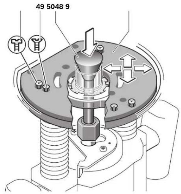
To ensure that the distance from router bit centre and guide bushing edge is uniform, the guide bushing and the guide plate can be adjusted to each other, if required.
Push the release lever 22 down and guide the router to the stop in the direction of the base plate 12. Let go of the release lever 22 again, in order to lock this plunging depth.
- Unscrew the countersunk head screws 49. Screw the pan head screws 48 into the holes intended for this purpose in such a manner that the guide plate 9 can be moved freely.
- Insert the centring pin 50 into the tool holder as shown in the figure. Hand-tighten the tightening nut so that the centring pin can still be moved freely.
Align the centring pin 50 and the guide bushing 47 to each other by slightly moving the guide plate 9.
Tighten the pan head screws 48.
- Remove the centring pin 50 from the tool holder.
Push the release lever 22 and guide the plunge router to the uppermost position.
For routing with the guide bushing 47 proceed as follows:
- Guide the switched on power tool with the guide bushing toward the template.
- Push the release lever 22 down and slowly lower the plunge router until the adjusted depth-of-cut is reached. Let go of the release lever 22 again to lock this cutting depth.
- Guide the switched on power tool with the protruding guide bushing alongside the template applying lateral pressure.
Maintenance and Service
Maintenance and Cleaning
Before any work on the machine itself, pull the mains plug.
For safe and proper working, always keep the machine and ventilation slots clean.
In extreme conditions, always use dust extraction as far as possible. Blow out ventilation slots frequently and install a residual current device (RCD). When working metals, conductive dust can settle in the interior of the power tool. The total insulation of the power tool can be impaired.
If the replacement of the supply cord is necessary, this has to be done by Bosch or an authorized Bosch service agent in order to avoid a safety hazard.
If the machine should fail despite the care taken in manufacturing and testing procedures, repair should be carried out by an after-sales service centre for Bosch power tools.
In all correspondence and spare parts order, please always include the 10-digit article number given on the type plate of the machine.
After-sales Service and Customer Assistance
Our after-sales service responds to your questions concerning maintenance and repair of your product as well as spare parts. Exploded views and information on spare parts can also be found under:
www.bosch-pt.com
Our customer service representatives can answer your questions concerning possible applications and adjustment of products and accessories.
Great Britain
Robert Bosch Ltd. (B.S.C.)
P.O.Box 98
Broadwater Park
North Orbital Road
Denham
Uxbridge
UB95HJ
Tel. Service: +44 (0844) 736 0109
Fax:+44(0844)7360146
E-Mail: boschservicecentre@bosch.com
Ireland
OrigO Ltd
Unit 23 Magna Drive
Magna Business Park
City West
Dublin 24
Tel. Service: +353 (01) 4666700
Fax:+353(01)4666888
Australia, New Zealand and Pacific Islands
Robert Bosch Australia Pty. Ltd.
Power Tools
Locked Bag 66
Clayton South VIC 3169
Customer Contact Center
Inside Australia:
Phone:+61(01300)307044
Fax:+61(01300)307045
Inside New Zealand:
Phone: +64 (0800) 543 353
Fax: +64 (0800) 428570
Outside AU and NZ
Phone: +61 (03) 9541 5555
www.bosch.com.au
Republic of South Africa
Customer service
Hotline: +27 (011) 6519600
Français|21
Gauteng - BSC Service Centre
35 Roper Street, New Centre
Johannesburg
Tel.: +27 (011) 493 93 75
Fax:+27(011)4930126
E-Mail: bsctools@icon.co.za
KZN - BSC Service Centre
Unit E, Almar Centre
143 Crompton Street
Pinetown
Tel.: +27 (031) 7012120
Fax: +27 (031) 7012446
E-Mail: bsc.dur@za.bosch.com
Western Cape - BSC Service Centre
Democracy Way, Prosperity Park
Milnerton
Tel.: +27 (021) 5512577
Fax:+27(021)5513223
E-Mail: bsc@zsd.co.za
Bosch Headquarters
Midrand, Gauteng
Tel.:+27(011)6519600
Fax:+27(011)6519880
E-Mail: rbsa-hq.pts@za.bosch.com
Disposal
The machine, accessories and packaging should be sorted for environmental-friendly recycling.
Do not dispose of power tools into household waste!
Only for EC countries:

According to the European Guideline 2002/96/EC for Waste Electrical and Electronic Equipment and its implementation into national right, power tools that are no longer usable must be collected separately and disposed of in an environmentally correct manner.
Subject to change without notice.
Français
Dr. Egbert Schneider Senior Vice President Engineering
Dr. Eckerhard Strötgen
Engineering Director
PT/ESI


Robert Bosch GmbH, Power Tools Division D-70745 Leinfelden-Echterdingen 26.10.2011
Montage
Robert Bosch (France) S.A.S
Dr. Egbert Schneider Senior Vice President Engineering
Dr. Eckerhard Strötgen
Engineering Director
PT/ESI
Paa /nue i.v. nuo:
Robert Bosch GmbH, Power Tools Division D-70745 Leinfelden-Echterdingen 26.10.2011
Montaje
Senior Vice President
Engineering
Dr. Eckerhard Strötgen
Engineering Director
PT/ESI
Paa
Robert Bosch GmbH, Power Tools Division
D-70745 Leinfelden-Echterdingen
26.10.2011
Montagem
Senior Vice President
Engineering
Dr. Eckerhard Strötgen
Engineering Director
PT/ESI

Robert Bosch GmbH, Power Tools Division
D-70745 Leinfelden-Echterdingen
26.10.2011
Montaggio
Senior Vice President
Engineering
Dr. Eckerhard Strötgen
Engineering Director
PT/ESI


Robert Bosch GmbH, Power Tools Division
D-70745 Leinfelden-Echterdingen
26.10.2011
Montage
Senior Vice President
Engineering
Dr. Eckerhard Strötgen
Engineering Director
PT/ESI

Robert Bosch GmbH, Power Tools Division
D-70745 Leinfelden-Echterdingen
26.10.2011
Montering
Bosch Service Center
Telegrafvej 3
2750 Ballerup
TIf. Service Center: +45 (4489) 8855
Fax:+45(4489)8755
E-Mail: vaerktoej@dk.bosch.com
Bortskaffelse
El-varktoj, tilbehor og emballage skal genbruges pa en miljovenlig maed.
27 Utsugningsadapter
Dr. Egbert Schneider Senior Vice President Engineering
Dr. Eckerhard Strötgen
Engineering Director
PT/ESI


Robert Bosch GmbH, Power Tools Division D-70745 Leinfelden Echterdingen 26.10.2011
Montage
Bosch Service Center
Telegrafvej 3
2750 Ballerup
Danmark
Tel.: +46 (020) 41 44 55
Fax:+46(011)187691
Avfallshantering
Dr. Egbert Schneider Senior Vice President Engineering
Dr. Eckerhard Strötgen
Engineering Director
PT/ESI
ppa. 1000 i.v. nuOycu
Robert Bosch GmbH, Power Tools Division D-70745 Leinfelden-Echterdingen 26.10.2011
Montering
Senior Vice President
Engineering
Dr. Eckerhard Strötgen
Engineering Director
PT/ESI
Paa
Robert Bosch GmbH, Power Tools Division
D-70745 Leinfelden-Echterdingen
26.10.2011
Asennus
TAnpopopiec yia bOpbo kai dovnoic
Oiuee pertonc tou bopou Eakpiowkav kata EN60745.
HxapaktnpiotnntaognknoumncnOopBwTou naxavnataoc EKTUNKNEOUPPAWcTNVKAUMN A KAVEPXTAI OE: 2tAunkauoTNIIC NIEAC 89 dB(A).2tAumakouTNIc ToXUC 100 dB(A).AvoepdAemuptnpnC K=3dB.
Φopàre wασηδες!
Ouovolke TIEc Kpa6aouv a (a0poiauvauautwpiav kateuovoeuv) kaiavaopaleK eakpiowkav oupovae pTo nprotm EN 60745:
a_h = 5,5m / s^2,K = 2,5m / s^2
H 0rOgKpAbaawou avapepetai aoutc tic obnyie cexi metpneoiuwwa me pia diaikaaiaeptponctunonmevnt oToIaioTO npotnou EN 60745 ka mopei va
xpnooointheta onu uykpiunTwv diaopow nkeptikw evayaleiw. Eivai enianc katana vEv avnpawov unoyouq Tc emapuvoc anou Touk kpaououc. H atbum kpadaoov ouavapepetai avnnpooewuei tic baokec xphocuou pkaeiou cieu o npimwn, owc, nou to nkektipok epyaleio 8a xpoanonoi Biaipopetka, pe npoteivoeva epyaleia xupic enapkn ouvtipnon, toe n stabn kpadaoov umopevi eaivai ku in biipapetikn. Aut nponevi auhnei anauvtika tny cnbpavun anou touk kpaadoouc kataT ouvoukki diapkeia olakpou touxpvovku diaatmuotoc nu eyacebe. IaTnv akipBn ektnannc emapuvoc anotouk kpaadoaouc 8a npenei va laubavovtai eniunc unown kai xpovoi kata tn diapkeia twonokw to npaxnuva bpiaketak etxcac leitoupliac nleitoupeix, wpcic owcnv npayatikotnta va xpnoooneita. Au nponevi paewae onnaytika tnv
88EAAnvik
EiBapuAn anouc kpaabaouoc kata ndiapkeia ooknpou TOxpvKoioaotmaTOOepyaceae.
I' auto, npiv apxiai n dpao twv kpaadaaov, va kaobopicte ouannpawatka metpa aopaeia viy tvn npootaia tou xeiptn anoc: auvtponan tou nkeptikou epyaleiou kai twv epyaleicov noxpauonoeic, cataqa twv xcpiw, opyaewon tnc ekteaeonc twv diaqopow evayaiow.
△λωη Φμβατητα
C
Anwoume uneuvuc ot npoiou nou nepiypapctai oTa
TcviXaopaKniPiotkcknnpovciouc cKavovipoucn kataokeuaotke ouotaeic:EN60745 oupwa me Tc
diotaefic twoynyow 2011/65/EE,2004/108/EK, 2006/42/EK.
Teyikoc pakeoC (2006/42/EK) ano:
Robert Bosch GmbH, PT/ETM9,
D-70745 Leinfelden-Echterdingen
Dr. Egbert Schneider Senior Vice President Engineering
Dr. Eckerhard Strötgen
Engineering Director PT/ESI


Robert Bosch GmbH, Power Tools Division
D-70745 Leinfelden-Echterdingen
26.10.2011
EuvaopAoynon
TOnoTeTnOn Tou epyaleiou PpeZapiaogatoc (BLeNc Eukova A)
ByaTeToPcAnoTnVnpa npv ano onoudiHnote epyaia oTo nEeKtpko epyaleio.
ououououe va opate npoataeutka yavta orav tonooteire naaaZeTe to epyaio ppeapiaqatoc.
AiaTHeVtApyaIePpeZapaiopacoe diafopecekdoeckai noTntc, avaloya mcynckaoTc xn.
Epyaieia ppezapiaqaroc ano rauxuaubu npnla
anooecivai katalaaia vaytnkatepyaia paakawuikw,pi.xpaakawvauawkai nlaotikw.
EpyAeia ppezapiaqatoc me koice ano kAnpoepaalao elai eikakataanlAe iayntkateyiaoknawkv anoTeiKuivuikov, n. x. kAnpwFouwkv kaIauovliou.
Ta ynaia eaptna apecpalopatoc and to ktevec npovpaia eaptnatw vnc Bosch unopeite va npountheute an tov apodio iaac efouoiodotnevo cunopa.
Na xonaiipoioiie Ioov apioTec kaiKaapec ppeEc.
Tnpoue to 6ikalua aahayv.
Türkce
Güvenlik Talimati
Elektrikl El Aletleri icin Genel Uyar Talimatu
AUYARI
Dr. Egbert Schneider Senior Vice President Engineering
Dr. Eckerhard Strötgen
Engineering Director
PT/ESI
Paa Maae i.v. Mojgc
Robert Bosch GmbH, Power Tools Division
D-70745 Leinfelden-Echterdingen
26.10.2011
Montaj
Frezeucunun takilmasi (Bakiniz: Sekil A)
Bosch San. ve Tic. A.S.
Ahi Evran Cad. No:1 Kat:22
Polaris Plaza
80670 Maslak/Istanbul
Bosch Uzman Ekibi +90 (0212) 367 18 88
Tasfiye
Dr. Egbert Schneider Senior Vice President Engineering
Dr. Eckerhard Strötgen
Engineering Director
PT/ESI


Robert Bosch GmbH, Power Tools Division D-70745 Leinfelden-Echterdingen 26.10.2011
Montaž
System Constant Electronic
Robert Bosch Sp. z o.o.
Dr. Egbert Schneider Senior Vice President Engineering
Dr. Eckerhard Strötgen
Engineering Director
PT/ESI

Robert Bosch GmbH, Power Tools Division D-70745 Leinfelden-Echterdingen 26.10.2011
Montáž
Bosch Service Center PT
K Vapence 1621/16
692 01 Mikulov
Senior Vice President
Engineering
Dr. Eckerhard Strötgen
Engineering Director
PT/ESI

Robert Bosch GmbH, Power Tools Division
D-70745 Leinfelden-Echterdingen
26.10.2011
Montáž
Dr. Egbert Schneider Senior Vice President Engineering
Dr. Eckerhard Strötgen
Engineering Director
PT/ESI
Paa
Robert Bosch GmbH, Power Tools Division
D-70745 Leinfelden-Echterdingen 26.10.2011
Osszeszerelés
Yka3aHHIIO6e3oTacHOCTH
06uye yka3aHnno To texnke 6e3oNaCHOCTN AAN 3AEKTPOHCTpymENTOB
PENEYIPEXDEHME
IpoHTHe Bce yKa3aHHN H
HNCtpyKUH NTOTexHHKe
6e03aocchth. Heco6a0eHney kkaahnnn HnHCTpykui nTO texHMke 6e03aocchto MOKet CTbI pInHHoT IopaeJHenn AaKTEpHeCKM TOKOM, IQKAPA nTRKeAbl TPAOB
CoxpaHnTe 3TH HnCTpyKuHH yKa3aHHA AAR 6yDuero HCToA630BaHHA.
HcnoB3oBaHHoe B HactoIHXN HCHTpKUHX N yKa3aHHX IOHTHe KAEKTPOMHCTpyMeHTPacpOCTpaHHETCn HA AEKTPOnHCTpyMeHT CNTaTHeMOT CTeH (CCEtEBbIM SHypOM) Ha AKKyMaYTAOPbH N AEKTPOnHCTpyMeHT (Be3 CeTeBOrO WHypa).
Be3onacnoctb pa60ery Mecta
CaepeKne paOoe MeTO B uHcTeTHe XoHOO OCEeHHbE. BcToPraOKn HNeEOBceHHeYuACTKn paOoeMeTaMOTyPIPNBECTN KHeCACTbHN CAYaAM.
He pa60taIe C 3TNM 3AekTPOHnCTpyMeHtOM BO B3pBBOOITACHOM TOMeUeHHN, B KOTOPM HAXOaTcR TOpOHue XmKoCHTH, BOCIIAMHeIOUHEC RA3bI HAN TbAb. 3AekTOHCTpyMeHTbI NCKPrt, QTO MOKET PIPBECTN K BOCTIAAMHeEHIO TbAIH HAN IAPOB.
BoBpMa pa60bI cAeKtpOnHCTpyMeHToM He OYONCKAe3KO Kaewmy paOcMy MeCyTeTne IOTOPOHHXu.OTBAeKUHcB, BbMOKeTeIOTePrtb KOHTPOAb HAD 3AEKTPOnHCTpyMeHToM.
3aektpo6e3oTnachoctb
WITENCEA HAN BNAKA 3AeKTPOHNCTPymEna DOXHAnTOAOANTb K WITENCEA HON PO3eTKe. HN B KOEM CAYae He N3MeHNrTe WITENCEA HNYO BNAky. He PImMeHnTe TepexoAHBle WtEKepbI AAD 3AeKTPOHNCTPymENTOB C
3aunthbim 3a3emAHHem. Hn3MeHHHeBt WTeTceA hBHe BAAKn ITOAOJUHn WTeTceA hBHe pO3ETK CHNJaOT PCK TOpaxEHn 3AEKTPOTOKOM.
IIpeoTbpaaHTeAeChbIKOHTAKC3a3EmeHHBMIOBEPXHOCTAMK,KAkTO:C Tpy6aMn,3AEMeHTAMNOTONAHN,KyXOHbHMNTAMM HXOAQDAHBHKAMn.1Pn3a3eMaehn BaWeroTeaIOBbIaETCRpCKTOPAKEHNE3AEKTPTOKOM.
3aHnHaaTe 3eAekTPOHHCTPymEHT OdoXHa HcbipocTH. IpoHHKOBHeHHe BOaB B AekTPOHHCTPymEHT IObBlaet PnCK TOpaxEHn 3AekTOPTOKOM.
He p3peaetc Hc0Ta3oBaTb Hhyp He nHa3HaueHHIO, HApHMeP, A4 TpaHCnOpTHPOBKN HAN OaBBeCKN 3AEKTOOHCTPYMEnTA, HAN DAA BbTTBAHNNBNAHN BAAKN H3 WTeNCaBHOH PO3eTKN. 3aUuAaTe WhypOT B03eHCTBNB BYCOKHX TMNEtepaTp, Macaa, OCTpbIX KpOMOK NIOaBnXhBXb XACTe 3AEKTOOHCTPYMEnTA. TObPexdHbH Hn Hn CNYtaHHb HHyp TOBbIaET PCKN Topakhen 3AEKTOTOKOM.
PpH pa6Ote C3AeKtpOHnCTpymENTOM IOA OTKpbITbIM He6OM pIIMEHNEI PPHoADHIE DAA 3TORO Ka6eAHYAMHHTEAN. PIIIMEHNE IINrOAdHO DAA pa6OtBI POATKpbITbIM He6OM Ka6eAA-YaDHHTAE CHHXAEt PHCKTOPAKEHN3AeKPTOTOKOM.
ECAH HeB03MOXHO H6ExaTb TIPMeHeHHN 3AEKTPoHHCTPymeHTA B CbIpOM TOMeueHHN, NOAIOUaTe 3AEKTPoHHCTPymeHTpee3 yCtpoHCTBO 3aIHTHORO OTKAIOUeHH. TIPMeHeHHe YcTPOHCTBa 3aIHTHOrO OTKAIOUeHH CHHXaET PnCK 3AEKTPuueckOrO nopaxehn.
Be3oTachOCTb AIODei
BybteBHMMatBbHBM,CAeHTe3aTeM,TOBbI Aaete, HPOyMaHHo HAuHnHaTe pa60ty C3AekTPOHnCTPymrHOM. He TOb3yHTecb 3AekTPOHnCTpy-MENTOM BYCTaAM CoCTOHHN HAN ECAN Bbl HAXoANTECb COCTOHHN HAPKOTHeCKOHO HAN AAKORAaHBOr OTbRHeHHN HAN IOA BO3AEJCTBHEM AEkApCTB.OAHMOMEHT HEBBHMATeABHOCTHIPn PAoTEc 3AekTPOHnCTpy-MEMTOmKOT IPHBECTN K CepBe3HBM TpBaMam.
TIPMHENHTE cpeACTBa HANBHBAYaBHO3aunHTbH BcERda 3aunTHbIe OUYK.NCTOAB30BaHHe cpeACTB HINBHNyAbyBHO3aunHTbI, Ka TO: 3auTHOH MACK, OByBN HA HECKoB3aJIIe IIOAOIBE, 3aunHTHO TILMAH Nn CpeACTB 3aunHTbOPrAHOB CAYxa, -B 3aBNCMOCTH OT BHa da pa6OTbC 3AEKTKPOHHCTpyMeHOM CHXKAeT PnCK IOAyuEHN TpaBM.
PipeoTbpaaHte HnpeDnAmepeHHoe BkIOUeHHe 3AEKTPONHCTpyMeHTa. IpeE TIOKAIOUeHem 3AEKTPONHCTpyMeHTa K AIEKTPOTNTAHNO H/MAN KAKKY MYAHTOPY6BdANTECb BBIAKIOUeHHOM COCTOHHN 3AEKTPONHCTpyMeHTa.YdePKHaHE TAAbHa Ha BbIKAOyATEe PIP TPAHCTOPTHPOBKE AIEKTPONHCTpyMeHTa N IOKAIQHOHNE K CEMI TINTAHNA BkIOUeHHOrO 3AEKTPONHCTpyMeHTa YpeBaTO HecuACTHBIMCAYAARMM.
Y6npaIte yCTaHOBOUHb MHCTpMEnT HAN raeHbIe KAOHn DO BKAIOUeHHN 3AEKTPoHNCTpMEnTa.

Pycckn | 129
HnCTpyMeHT HAN KIOU, HAXOaIINCRA BO BPAaIooIECAACTH 3AEKTPONHCTpyMeHTA, MOKET PnBbECTN K TpaBMam
He npHHMaIte HeecCTBeHoe IIOOXeHne KOpTyca TEA.BcERda3aHHMaIte yTOHNBoe IOAOXeHne M coxpaHnIpe paHBoBeCe.5aIarOapr 3OMy Bb moKeTe Auyue KOHTPOAnPobAtb AEKtPOHNCTpymENTB HEOKJAdAHhBix CNTyauiX.
HochtnepoXoArypo paOoyoOeXyHe hochtne HOPKyoOeJMy NKpaewHn. AepxNte BOACbI, OeJy NpykABuBBAaAMOT ABHXyUxxCraCTeH. 1pOKaR OeJda, yKpaewHn HAANHbBEBOLCbMOrYT 6bIt b3rHTbBPAaouHMnCuaTAM.
Pn HAANH NBO3MOXHOCTN yCTAHOBK nTBAeOTCacbIAOHN H TbAeC6OpHBx YCTPOBCT nPOBeprHE Xn PnchoaENHeH NTPaBnAbHo HNC0A3oBaHHe. PNIMHeHNE HnIAEOTCOCA MOXET CHINHTb ONACHOTc, CO3dABAAemyIO TbAio.
PpHmEHeHHe 3AektpOnHcTpymEnHa 06paueHne c HMM
He neperykaite 3eKtpOHCTpymENT. HcnoB3yte ABA Baeu paobtI ppeH3aHueHHb IAA 3TOI 3eKtpOHCTpymET. CIOXoAuaHMM 3eKtpOHCTpymEH TOM Bbl paobotaTe AyuHnHaJExHBe yKa3aHHOM dnaHaoHO MOnOCHN.
Hepa6oTaTe C3AekTPOHNCTPymEMTOm Pn HENCTPABHOM BbIAKUOATEAE.3AekTPOHNCTPymENT, KOTOpBHe IIOAdaTCBIAIOUeHHN Mh BbIAKOUeHHN, OITaceH NdoXeH 6bItb OTPEMOHTPOBOAH.
Ao hauaHa Haaakn 3AektpOHNCTpymEnTa,peepaepenempa0b0tB OTKAOUaHTeIHTENCeBAHbY BAAKY OTpOETKN CTH HAN BbHBe AKKMYAATOp.3a Mepa IpeoC TOPOXHOCTn PEPOTBpaAaET HePpeDAHapeHHeB BKAIOUEHNE 3AEkTPONHCTpymEnTA.
XpaHHTe 3AekTPoHHCTpyMeHTb B HeEOctYTHOM DAH
DETeM MeCTe. He p3aPseWte NOA3OBATbc 3AekTPoHHCTpyMeHTom AHcAM, KOtOpBe HE 3NaKOMbI C HMM HN
HE YHTaAN HACTOuINH NCTpyKU, 3AekTPoHHCTpyMEHTbl OTACbH B PYkAX HeOTbTHbIX AML
TuaTeA hO yXaxHbAte 3a AektpoHHCTpyMeHTOM. TIOBepnIe 6e3ynpuehyo fHKuHO XOA DAHXyUHcCra HcTeE3AektpoHHCTpyMeHTA,OTCYCTBHe TOAMOK HAN IOBpeKdHm,OTPHaTeA bHO BAHNouHx HAfYHKnO3AektpoHHCTpyMeHTA. NOBpeKdHbIe qACTHdoAKHbIb6bITb OTpEmoTHPOBaHbI O HCToA b30BAHn3AektpoHHCTpyMeHTA. IAOxoE oCayXHBnE 3AektpoHHCTpyMeHTOB RAABETCR pINHNO 6oABWTO YCAAAeCHAcTbHex CAYaEB.
AepxHtpeyxuHHHCTpymEnB3aToeHHOM H NCTOM COCTOHN. 3a60TANBO yXoXeHHbIe peyuXue HHTCPyMeHTbC OCTpBmHpeyxuHHKPMOKAMn PKeze 3aKaMHNBAOTC INX AaeYe BEcTN.
PpHMeHnTe 3AeKTPoHnCTpyMeHT, PpHnHaAeXHoCTH, pa6OHe HnCTpyMeTbI H.T.I. B COOTBETCTBN C hACTOnuHMn HnCTpyKUHMn. YcHTbIAHTpe pN 3OM pa6OHe yCAOBHn H bblOAnReMyo pa60Ty. NcToIb3OBAHne 3AeKTPoHnCTpyMeTbO DAH HePeDAyCMtpeHHbIX pa60T MoKET pINBeCTN K OITaChbIM CNTyaUNM.
CepBnC
Pemont BaWero 3AeKtpOHnCTpyMeHTa NopyaHTe TObko KBAANPHIOPOBAHOMY TepCNOHY NTObKO C pIMHeHEMOpOHNHbAlbHX 3aNtBbX aTae.3THM o6ecneuBaetcBeoIaONACObTbAeKtpOHnCTpyMeHTa.
Yka3aHHIO TEOxHnke 6e3oTachOCTN AAR Φpe3epHbIX CTAHKOB
063aTeAbeHdoepxHe 3eKtpOnHcTpymEt 3a HnpoBaHbIe pyKn, T.K. Fpe3a MoKet 3aenntb co6ctBHeHH bHyp nHTAHn. KOHTAKC HaxoAmeCn IIOHaNpJxEHHE mPOBOkO MKeT 3apKaTb MetaAahueckNe qACTn 3eAeKpONHcTpymEt N pRBOHtK ydApy 3eKTPHcEeKHM TOKOM.
3AkpeTnHΦHKmpyHe 3aTOrOBky HA c7abHbHom OCHOBAHN C TOMOuMbCTpy6uHb HAN ApyHM CNTOcOBM. ECAH Bbl 6yTeYEaepKHBaTB 3aTOrOBky PkoH HAn pIPhXHMaTb ee K c6e, ee IIOAOxEHNE 6yEt HEoCTATOUHO CTABHb, B pe3yAbTaTe Yero BO3MOxHa yTpA t KOHTPOJH.
AnyctHMoe qHcAo 06OpOToB pa6oery HnCTpyMeHa OaXHO 6bIb He MeHee YK3a3HnHO Ha 3AeKTHPOHHCTpyMeTaeMakChMaHbHO rCa a6OpOToB. PnHdAExxHcOHTb, BpaiaouHecc c 6oJbWe, HEM AnOyCTmO CKoPocTbO, MOYr PA3OpBATcBc.
Φe3bH ApyIe TpHnAaExKHOCT HOnAaXbI ToH0 TAOxOaHTb K 3aXHHMOn IaHre BaUero 3aOTKPTPOHcTpyMeTHa.PaOouHe NcHcTpMyTeB1,He COOTBeCTByOuOHte TOH0 3aXkMy3aEKPTPOHcTpyMeHTa, BpaAaOTc C6HHeHM, CnBHO Bb6pPyOT H MOrYt TIPINBECTK NTOpe KOHTPOAA.
TOABOAHTE3AEKTPOHHCTPYMHTKDAETAH TOAiko BO BAOHAOHOM COCTOHH. B IPOTNHBOM CAYae BO3HKAeOTIaCHOCTbOpaTHoYdapaPiN3aKaAMHHBaHH pa6oOero HCHPTyMAB DETAHN.
HeoctabAHTe pykB30hyΦpeepobAHnHtoa p Ey .BauBTOPApykoAOXHAOXBATbBATOAHNTeABHyPOKRTKYHANKOPITYCABHrATEAR. EAnBaOnObe pyknaHOAXOTCHHaΦpeepOMCTaHKe, OHHeMOrT6bHTTbpAMIPOBAHbIΦe30i.
Hepe3epyHnKOrA TIO METAAANHECKHM TpeAMETAM, TB03AM HAN BHTAM.Φe3a MoKet 6bItb TOBPEKJH N PINTECT KTOBISHHEN BIVpaanin
HcTIOb3yIe COOTBETCTBYIOUHe MeTaAONCKATEAH DAA HAXOXDAHNN CNTPAHHBX B CTNE Tpy6 HAN TPOBOADN MAN O6paJIaTeCb 3a CPTpABKO B MEcTHOE KOMHYAHOE PnEPnPHrHE.KoHTAC T 3AEKTPOPOBOAO KOET PnPBECTN KTOXAPY N TOpaxEHNO 3AEKPTOKOM. POBPEXDAHNE Ra3OTPOBOdA MOKET PnPBECTN K83pBy. POBPEXDAHNE BOOTPOBODa BEAET K HAHECEHMO MATEPNAHBOHO YUepeBa MAN MOKET BB3BaTb NopaxEHNE 3AEKPTOKOM.
He TpHMeHnTe TyTbIe MAN IOBpeXeAHHbIe fpe3bl. TyTbIe HAM IOBpeXeAHHbIe fpe3bl CO3AoiT IOBbIeHHoe TpeHne, MOrY 3aKmHNHTCBn HBeyT K DnC6aAahcy.

130|Pycckn
Bcerdaepxhte3AektpoHCTpyment BO BpMa p60tbo 3a6bHH TpeDABpHTeALHO yctOHNBOE TOAOXHeN. ABym pykam Hblpa6oTaete 6oAee HaexKHO C3AekTPOHCTPymETOM.
BbIXAHTIOAHOHOCtAHOBK3AEKTPOHCTPymeHTa H TOBkoTOcAE3TOrO BByIcyKaIteeroHpyk.PaobouH IOHTPYMHTMOKET3AECTb,HI30MOKETIPINBECTKNITOTEpe KOHTPOAHAAD3AEKTPOHCTPymEHTOM.
Onncnne npoaykta n ycayr

IpoHTe BCE yka3aHH HnHCTpyKuHH TEOxHHK63oTACOCHTH. YyueHHB OTHoUeHHYk3aHH N HnCtPYKuHH TEOxHHK63oTACOCHTH MOrYT CTaB IpnHHOIOPAxHHN 3AekTpueckHM TKOM, IOXapa NTRKeABxTPaBM.
I0kaIyIcTa,OTKPOITe paKAAADHyO CTpaHnUc
IIIOCTpAaMHN 3AEKTPONHCTPymEnTA H OCTABARNE ee
OTKpbTOn, noka BbN3yaTe pyKOBOAdTO IO KCIAYataaHH.
TpImeHeHHe To Ha3HaueHHo
HaCTOaHm HnCTpyMeT npeHa3haueH Aa Ppe3epoBaHna Ha pPOuHOM OCHOBAHIN PA3OB, KpOMOK, IPODHeN I IPOAObHXOTBpCTnB DEPECnHE, INACTMaCCax N AERKHX CTPOHTeA bHX MaTePAHAX, a TAKOE Aa KOITNPoBAbHOrO Ppe3epoBAHn.
ITPNIOHMKHeHOMUHCAEOBOPOTOBICCOOTBCTBYOUMMΦpe3AMMOKHO6paBaTbBaT TaKkeIUBETbIeMeTAAJI.
H306paXeHHbIe COCTABHbIe YACTN
HymepaunI pndctTaBAAHHbIX KOMTOHEHTOB BBIOAHEHa IIO306paKeHNHO hCTpAHue C HNOCTPAUNRM.
1PyKoRTaCnPaba(CH3OAMPOBAHHOIPOBExHOCTbIO
2 KHTkaΦHKCNPOBaHnBbIaOyATEA
3YCTaHOBOUHoe KOLECHKO UcCla 06OpOTOB
4PbUarФнкацишнIHaeA
5BapawkoBb BnHTAa npaaeAho ynpa(2wT).
63aunnta oT ctpyckn
7Φpe3a
8 KpeHHeHne HappaBAAIOx CTepXHeI TapaAeAboHorO ynpa
9ПANTAСКОАБKEHIN
10 CtytneHuaTbI ynp
11HactpoeUhBbE BnHtbl CTytnEnHaTorO ynpoa
12 OToPnHaTmTa
13 3aunthar MaHxeta
14BapawkoBbBNHTAHACTPOKnOprAHHHTeA rhy6HHbl
15 OrpaHnUHTeIb Iay6HHbl
16ПОАЗУHOKСИНDEKCHOIOTMETKOI
17PyKoRTKa CLeBa (CnOAMPOBaHHOIOBEPXHOCTbIO)
18UkaHacTpoKnIy6bHbIΦpe3epoBaHn
19ⅢKaaTOKOHnactpoKNrAby6HbIppe3epoBaHH
20PykaToHKnHactpoKnTay6nhbΦpe3epoBaHH
21MapKnpoBkAaCorIacOBaHmTOuKn Hya
1619929J79|23.11.11 Bosch Power Tools
22PbUar pa36KOpBKN
23HaKuaHaaIaKaC3aKMMHOaHro
24 BbIKIOUoyATEAb
25FaeyHbI KAIou 24MM
26 LAAHrOTcAcbBAHH(035MM)
27Aaantep oTcabBaHH
28BnHCT hakatKoA HrO TcAcbBAIOUeero aadTpe (2Wt.)
29 TapaMaMeAeBHybYynp
30 HapabAAHounn CtepxeHb npaAeBHO yTopa (2 wT.)
31BapawKOBm BHTAIIpaaMaeHbHOynpa yCTPOJCTBaTOHKoHAcTPOkN(2Wt.)
32BapaWkoBm BnHTAIIapAAeHbHO yIopAp yctpoCTBa npy6oHaCTPOHKn (2 wt.)
33Pyuka da npaaalebHoro ytoopa hactpoKm
34 Peryanpyemar ynpnHnIaHKa IaI npaaeBHorOynopa
35 Otcbibaiouian aadTep dIa TapaMaBHOrO yToPA
36 Φe3epHbIyIuPKyIb/aIaIITp HapBaIIOueI peKn
37PykaΦpeaeepHOroUnpkyA
38BapawkoBbBnHTAARpy6oHactpoiKnΦpe3epHOrO uPKyA(2Wt.)
39BapawkoBbBnHTAANTKOBHACTppoKNΦpeepHOrO uNpkyA(1Wt.)
40PykaAaTOnKoHacTpOKnΦpe3epHoroUnpKyAA
41LcHTpnpuyoui60aTuipkyabHoro yonpa
42PacnopHaa nAnTa(BXoAHT B KOMTAAeK TΦpe3epHoro UnpkyA)
43HannpaBAAIOJaapeKa
44AaantepKoHnPOBaHbOHrHa3blSDS
45KpeTExhB BnHT AaAaITepa KOTINPOBaIbHOI Ia3b(2wT.)
46PbUar pa36AOKHPOBKn aDAnIepa KONHPOBaHbHOr HnAB3bI
47KoTnPOBaAaBHaRnAba3a
48 LIMHADPHNECKHN BINT DAI TANTbCKOALKHEN
49BHTCITOTAHHOIROAOKOKAANTbICKOABXEHN
50 Onpabka ceHTnpoBaHnHa
'H3o6paXeHbIbe HAIOTHCaHbIbe IINHAAEXHXOCTNHE XOADT BCTANADPTbIb ObEBMTOCTABKII. POAHbI aCOPTMMENT IINHAAEXHXOCTe BblHaJeTe B hAwe Tporpamme IINHAAEXHXOCTei.

Pycckn | 131
TexHueckne DaHHbe
Texnuecka DOkymentau (2006/42/EC):
Robert Bosch GmbH, PT/ETM9
D-70745 Leinfelden-Echterdingen
Dr. Egbert Schneider
Dr. Eckerhard Strötgen
Senior Vice President
Engineering Director
Engineering
PT/ESI

Robert Bosch GmbH, Power Tools Division
D-70745 Leinfelden-Echterdingen
26.10.2011
C6opka
YcTaHOBKaΦpe3bl (cm.pnc.A)
IpeaeAIObHMMAHHTYAAUHMMC 3AeKTPoHHCTpyMeHToM BbITaCKHBaTe UTeTceAb N3 pO3ETKN.
AaYcTaHOBKn CmEhblΦpe3bl peKoMeHApetyetcnoB30BaTbCra 3aunTHbIMn EpuATKaMn.
B 3aBnCHMOCTN O6bAactTINPIMHeHnB pACIOPAKeHHnHEIOTCApaANHbIE NcIOAnHeHnK aKeCTBaΦpe3.
Φpe3bH 36bIcTpopejxuee CTaAN TOBbIeHHoH
IPOUHOCTIpeHa3HaueHbIaOBpa60TKM
MaTePnaAOB,HaIP.,MAKoN ApeBeCnHbI N IaCTMaCcbI.
Φe3bCTBepoCTAABHBMIIaactHHM Oco6eHHO
TnHOaHbI AAR TBePabix H a6pa3NHBx MATEpHaIOB, HAIP.,
AA TBPdApDEBeCCHbI AALOMHHI.


132|Pycckn
OprrnHaBhIbe ppe3bH 06uHPOH TpOpamMbI
PnHaAeXHOCTe HpMBo Bosch MOxHO TpHObpeCTN B CteuaaHINPOBaHOM Mara3He.
PImMeHnTeToaBko6e3yKOpn3HeHHbIueHcTbeΦpe3bl.
- TObepHnTe BHN3 3aunTy OT ctpyK6
-Повернente рьгб 6LOKHPOBKN WIIHHDAE4 NO yacobOB CTpeAke H AEPKHTe ERO B 3TOM TNOXHEHN (O).Трп Heo6xOaHMOCTN Повернerte pyko BAI ABIRatae Ido er0 6LoKHPOBKN.
-OTNYCTHe HAKHADHYO rAky 23raeYHBIM KIOQOM 24 MM 25, BpaaaereroipotnbacOBON CTpeKn (2).
BCTaBbTe pfe3y B3axmMHyu cHry. XBOCTOBHK pfe3bl DOXHE BOHTB 3axmMHyIO cHry KAK MHHMym Ha 20 MM
3aTHHTHEKANHHyraKy23raeHbIMKAIOHOM24MM25,BAIpaAeroTOcAocOBnCTpeAke.OTyCTHe6AOKPObky - NoBepHnTe HaBepx 3aunTy oT ctpyKKn 6.
He yctahabbaBnate fpe3bI cHAmETpOM 60Aee 50 MM 6e3 KOthpoBaHbOHrHa3bI.3TH fpe3bI He npoxoAR Tpe3 OTOpHyIOIANTY.
HnB Koem Caayae He 3aTnBaIte HauKdHyraKy 3axMHMOuTH6e3pe3bI. HauHe 3axMHHa LaHr MoKet 6bItbTOBpEkaHeA.
OTcOC TbIH N CtpyKk (cm.pnc.B)
IIbHEKOTOpBxMATEpHnAOB,KaHnP.KpACOK CcOepKAHNEMCBNHUA,HEKOTOpBxCOPTOB DpeBEcnHbMIHHepAONMBetaMOB,MOeTbBBePAHOI3ADJ3AOPOBB.IPIHKOCBOHHeKIIbIMNIPOAAHNEIbIMBdIXATEbHbIXITNMOXETBb3BaTbAAePRUeCKHepeAKmN/MAH3ABoAEBAHNrDbxATeALbHbIXITyTeONEPaTOPaHANHXoDAIIECR6B6hNTHIpeCOHaA.OTpeAEENHbIEBVbIbHnHAPy6aNByka,CHTAIOCTKaHCUPEROHBM,OCoEHHOBCMECTHO CIPNCaKMAMDAOB6pa0BtKNDePEBCnHb(XPOMAT,CpeACTBOAAN3aUNTbIApDEBCnHb).MATEpHCAcoEPAHnEMAcEcTa pa3peWaeTcO6pa6aTBbAtTohkoCneuMaNTam.
-IT0B03MOXHOCTNHCNOa3yTeTIPHROHDbIAA MATEPnAaTbAeOTCOC.
-Xopoio npoBepnBaIte pa6oe MeTo.
- PeKOMEHyETCAIIOAB3OBAbCBApeCTNHPaTOPHOI MACKOICnAEBPOMKACCaP2.
Co6a0aTe DeCTBMyIe B BaIeI CTpaHE TpeAINcaHnA
Aor 06pa6aTbIbAembx MaTePnaAOB.
H36eraTeCKoTaeHHNbIaHpa6OeMMeTe.PbIaMOKETAERKOBOCTIAaMEHrBcR.
YctahOBKa aAaTpepa OTCacbIbAHN
OtaCbIaIOUaI aAITnep 27 MoKet 6bItb YcTaHOBaeH C
TIPNcoAIDHEHHeM IuaHa HrAePn HnHa3a. PnH
yCTaHOBAEHOM aAITnep KOITPOBaIbHOH TINb3b44 BaM,
MOKET 6bItb, PtNDcERY cTAHOABH bAAITp KOTPOBAIbHOH
TINb3b4 B TOBEPHyOM Ha 180oTOAOKEHH, YTO6bl
OTcAcBIAIOUaI aAITnep 27 He KacaCAh PBuHa
pa3AoKOIKPOBKn 46. PnTcAHOBKe IpcOcAIDHEHn IuaHa
CTpeHn Heo6Xdmo CHaHa A ChTb 3aunTHbN EkPaH 6.
3AkPeTIe OTCacBIAIOUaI aAITnp 27 ABMy BNHTAm C
HakAtKo 28 HA TnTE OCHOBAHN 12.
TpiHcOeMHeHMe TbIaeOTcoca
HacaHTe 1AaHTOcAcBBAHN (035 MM) 26(TpHaDAEEXHOCTN) HaYCTaHOBAAHHbIaADTepOTcAcBBAHN. CoaHInTe HAaHTOcACBaHIN 26 CTbIAECOCOM (TPHaDAEEXHOCTN).
3AektpoHnCTpymENT MOKET 6bTb TNOKNoey HPNMO K
HTTECBAHOBPO3eTEy YHBEPCaALBOHORTO BIAECOCa DPMbl
Bosch C yTPOrCTCBOM DcTAHIOHOHRO Tpyka. TbIAECoc
ATOMOTUVECKN 3aYyCKaETCR PnB BKIAOUENHN
3AektpoHnCTpymEHTa.
TbIaecocdoXeH6bITPiHrOaeHAAOBpaBaIBaemoromatepna.
PpHMeHrTe CTEUaHBbI TbIAeOC DAOTcBaIBAHN OcO60 BPeHbIXAAN3DOPOBbBnAOBITbIN -BO36yDHTeAEpaKa HN CYXOH TbIH.
YCTAHOBKa 3aunTbI O TcpyxKn (CM.pnc.C)
BCTaBbTe 3aunHTy O TcpykKn 6 CtepeAn HntpaBAAHOUIOYTO Tak, YTObO hOA BOUAA B 3auenHe. Aa CHTNA BO3bMNTecb 3a aunHTy OT cpykKn I0 60kAm N bblHIne ee HABepx.
Pa60Ta c HhctpyMeHToM
Bkauoyenne 3AektponHcTpymeha
YHTbBaIte HATpXeHHe cTe! HAnpXeHHe HCTOUYHKa TOKA DOAXHO COOTBETCTBOBAT DaHHBM Ha 3A0DACKoTABAHKe 3AEKTOPHCTpyMeHa. 3AEKTOPHCTpyMeHb Ka 230 B MoYr pa6OtaTb TaKKe H pHn HATpXeHHN 220 B.
HacrpoKa qncla o6oPOTOB
C TOMOIObYO cTahAOHOHOFO KOLECKa 3 Bbl MoKETe yctAHOBHTb Heo6xoAnMOe YHCLO O6OpOTB TaKKe H BO BpEmr paBOtI.
1-2 HN3K0E YHCNO6OPOTOB
3-4 CpeAhee uHcAo 06oBpOToB
5-6 BBICOKOEYHCNAO6o6oPOTOB
PnHBeEHbIeB TaIaMHe3HaueHHRAABIOCTc
OpHEHTPOBQUYBIMN 3HaueHHMn. HeOBxOAMMOE YHCAO
06OpOTOB 3aBHCHOT MATEPHAA Hpa6OHyCAOBHN MOKET
6bITb OPTeAEEHO TpKaTHUeCKHM CTIOOCOM.
AAR BKAIOUeHH 3AEKTPOHHCTDyMeHTa HAXMHTe Ha BBkAI0uATaeB 24 N DEpXHTe ero HaxaTbIM.
AaKcPbAHn BkAoueA 24 BO BkAoueHHOM TOAOxEHn HAKMTE KHOITky KcPbAHn 2.
AaBbKAOeHn3AeKPOHNCTPMyEHToOTyCTHe BbIKAOUATEB24HnECN OH6bI 3aΦHKCNPOBAH KHOITOK ΦNKCCPOBAH2, XAKMHTNE OOTCYTETBe bKaIOuateB24.
3AeKtpoHHa CHCTema Cta6HAn3auHNCKOpOCTn BpaueHHa KOHCTAHTHA3AeKTPoHHa IIIOAedePjXnBaET YHCLOo 06OpOTOB Ha XOAOTOM XOyU INoA HArpy3KOIN PpAKTNHECN KHa TIOCTOHHOM yOboHe N o6CneYnBaet paBHOmePHyN pON3BOHTeNbHOCTb pa6ToIb.
IIaBhbl 3aYCK
3AeKTPONHbI PAAHBn 3aYcCK OrpaHHuBaET KpyTuaHIM MOMEHT PnB BKIOUeHHN H YBEAMNuBaET 3TNM cPOK C LyXk6bl ABINrTeAe.
YcTaHOBKa rAly6HbI φpe3epoBaHHa (cm.pnc.D)
YctahOBKy rAy6HbI ppe3epoBaHH pa3peWaeTcBblIOAHrToAboKIO pHb BbIKAOueHHOM3AEKTPOHCTpymHe.
Ipy6yIOHACrpoHKyIy6BnblIpe3epOBAHNR BbIOAHRNE CAEyIOUIM 06pa3OM:
-YCTAHOBHTE 3AeKTPONHCTpyMENT C3aKpeIeHHoHΦe30H Na IOAeXaUO6bAp6OTKeAaB.
-yctaHOBITEpyKTOHNOHACTPOKNIy6HNbI p3epeoBAHH20BcpeAHENoLOXKeHNE.BpaauTeAAR 3TOrOpyKU20DoTENPIOKAOTMETKN21HeCTAHYBT NOKa3AHHOHnAPCHyHKeNoLOXKeHNE.Pocae3tOrO NOBEPHIHTWkAY19HaK0
- YctahOBHTe CTyHEnHATbYynOp 10 Ha CAMyHO Hn3Kyo CTyHeB;CTyEHaTbYynOp OuyTHMO BXoADHT B 3aQETAEHHE.
OTTYCTHE 6aapuokobbl BHNTAADHPTOKNrpaHnHTeAraIy6hBb14TAKM06p3OM,YTOb6OrpaHnHTeBcY6hBb15MOCB6oHOpeMeMaTaC.
HaKMTHe Ha pblvqar pa36oKpOKBn 22 BnH3 N MeAeHHO BeaHTe Ppe3epHyIO MaunHy BnH3, Toka ppe3a 7 He KCHETcN NOBepxHOCTn DetAn. OTyCTnte pbHAR pa36oKpOKBn 22, YTO6bI 3a#HKpOBAb 3Tу Fy6Hny TOrpyKeHHa.
IpiKMMTE OprAHMHTEb IaybHb BHN3 15, YTObO h CEHa CTyTeHcTbY np 10. YctaHOBITE NoA3yHOK C
HHEKCHOOTMETKOH16BIOLOXeHHeOTOIOWKaAHEACTPOKNAY6MHbIpe3epoBaHHN18.
- YCTAHOBHTE ORpAHHNTeAB TAY6HHb15 Ha XEAaEMOE 3HAUEHNE H3ATBHTE BapawKOBBI BHNT AAD HACTPOKN ORPAHNYHTE AYY6HHb14 HepecTBAJIte 60AJIbe POAAYHK CINDAEKCHOH OTMETKOH 16.
HaxMHTeHa pbyar pa36AOKnPOBKN 22 N BBBeAMTe fpe3epHyO MaunHy B BepXHee IIOLOXKeHne.
Aa 60bwoi Iy6HbI φpe3epoBAHn CaeSyET BbIOAHHTb
HeckoBko pa6OxH pOxOoB C Mehwe TouHHo
CHMaEMoro cAo. C TomouBc TcyTHauTOro yToP a10
IpoeeC fpe3epoBAHn MoXho PA3eAHb Ha HeCKoBKO
CTyHeH. Aa 3TOr OYctAHOBtKeEaMyo TAY6Hy
fpe3epoBAHn C cAmO HpNk CTyHeBc TcyTHauTOro
YtoPi N Bb6peTe Aa NPBx Pa6OxH pOxOoB ChauaA
BbCOKne CTyTEHn. PacToHnBE MEXy CTyEHmM MoXHO
N3MeHHTB BPAuHem HAcTPOeHbX BHTOB 11.
Iocnip06horo 3axoDa BbMoKTe BpaueHem pykH TOHKHOCTPOKNFy6BnHbPpe3epOBAHN20TOUHO HAcTPONTb Fy6BnHpype3epOBAHNA HxEaEMoe 3HAeHene; AAR yBEuHNHFAy6BnHbBpaAaTEpyKpyIOPTNBACOBOI CTpeAKn,AAYMeHbWHeHFAy6BnHb-TIO YACOBONCTpeAE. PTrn1OM ukaa 19 CAYKHT DAp OPNEHtPOBNQ.DOHMN IOBOTOPOMpyKnBbIM3MeHReTe 3HAeHene Fy6BnHa
2,0 MM,aNEPMEHENHEMAOHYDNCKYEAEHNERBEXHROKpaJWKAb19-Ha0,MMaKCHMaJIbHO3HAeHNHEMNEHENRAUY6HHbIpeEepOBAHINCOCTABAR±8MM
ПИмрел:КЕАмгдубинФрзeрOBаMHСоCTABHET 10,0 MM,пг ПЮбHOMфрзeрOBaMHNTOluYEHOЗ3haueHne 9,6MM.
-Пинлдддддддддддддддддддддддддддддддддддддддддддддддддддддддддддддддддддддддддддддддддддддддддддддддддддд
TANTY COKALBXEHNE, HAPIMMEP, DEPBENHIIe 06P3K91, TAK YTO6bl FpE3a 7 PnH CTyCKE HE KACAAcB 3AOTOBKN. HAXMITE Ha pIbIar pa36AOKnPOBKN 22 BHN3 IN MEdAeHNO TpepeBdIe FpE3ePHyO MaHHy BHN3, NOKa YNOP TAYBHNb 15 He CAnEt HA CTyHEnHAtb YNOp 10.
- Pocae 3Toro yCTHOBHte uKaIy 19 Ha «O» H OTTYCTHTe 6apawKOBbBnHT 14.
- NpoeBHnTe pyuKy 20 Ha 0,4 MM/4 DeAeHnHa (pa3HnHa MEXy 3aAHHb m PaKTHuEckHM 3HaueHEm) ITO YACOBI CTPEKNE 3ATAHnHe6BapauKOBb BHNT 14
-Поберпту сановаehHyI rA6HNY ПрбнIMФрe3epOBaHnEM.
TOcyeTcHOBK TAY6HbI ppe3epoBaHH He HAMEHnE TOJIOKEHHe TOA3YHCA NHEKCHOH OTMekHO 16 Ha ORaPHHTeLE TAY6HbI 15, YTO6B Bb BCERda MOrn ONPeAEAnTH TeKuyuO TAY6HbN No Kkaae 18.
Yka3aHnI IO TpIMHeHIO
PtpaoxpanHe ppe3y ot ToAukOB uDapOB.
HapabaeHme ppeepoBaHHn Hpoeecc ppeepoBaHH (cm.pnc.E)
Φpe3epoBAHHe BcERda OAOXHO TPOHN3BOAHTbCnPOTNB HAnpRaBENH BpaueHHa Ppe3by 7. PnH TOnyTHOM Φpe3epoBAHH 3eKtponHCTpyMeHT MoKET BBICOKHTb y Bac n pyK.
-yctaHOBnTe JEAeMyKry6HHyΦpe3epoBaHn, CM. pa3aEy (YCTAHOBKa IAY6HNbHΦpe3epoBaHn).

134|Pycckn
-ⅠOCTaBbTe 3AeKTPoHnCTpymENT C yTaHOBaEHHOΦpe30Ha IIOAExaIyU O6paBOTke DeTaH BkAIOHTHe 3AeKTPoHnCTpymENT.
-HaMHTeHa pIyar pa36oKpOBKn 22 BnH3 n BeDInTe 而AEPHYO MAUHHY MEAENHO BHN3 DO AOCTKHeHHY YCTAHOBAAHONI YA6BnHbIpe3epoBAHH.OTNCTte Pbyar pa36oKpOBKn 22,TOb6I 3aFKnCpObaTbTY AByHINN NORpyKeHH.
-BbIOAHHIeΦpe3epoBaHHe c paBHOmePHoTIOaueH.
-10OOKOHANHHPOUeccaPpeaePobAHnCHOBaYCTAHOBITEBepTKAabHo-fope3epbHcTahOKBCAMoeBEPXHEIIOAOXHEH.
-BbIKAOHTe 3AEKTPoHnHCTpyMeHT.
Φe3epoBaHne CO BCtOMORAteAebHbIM yTopom (cm.pmc.F)
A06pabOTKN 60aBxN3 3aTOrOBK, HnPnMnep, A
pe3eepoBAHN 1308, Ha 3aTOrOBKE MOKHO 3AKpETNIb DOCKY
HIN IAAHKY B KaueeCTBE BCMOrAteABHoYOtPOHa
pe3eepoBaB DAOB 3TOI yToPA. IpeMeuIte
BePTKAbHO-phiepEBH CTAHOK CTIOUHEN HO CTPOHO
IMTNb CKOAbEHHRAOAB BCTOMORATEABHOYtPOA.
Φpe3epoBaHne KpOMOK HnIpoΦnAbHoeΦpe3epoBaHne
IpnPp3e0pOBAHN KpOkM Nn InpOphiAe Pp3a DoXHa6bIb OcHaaEHaHpaBAAUeIe TaIPOHnIaWAPKOFIOAUHINTHNKOM.
IIOBaeHTe BKAIOHEnHH3AeKTPONHCTPymeHT C6Oky K
TAEANTK, YTObS HATPaBAHOUaIcuaIpaNHa
IAPHKOTODAMHTIHKn Fpe3bYtIEpAChb BTODAEkaUyO
06paBOTKe KOMPKDETAAN.
-BeIte 3AeKTPOnHCTpyMeHT 06EHMH pyKaMn BAOB KpOKHM AetAH. CaIeHTE PTH 3TOM 3a PpMOYTOABHbIM PpHaERAHm. CAnIKOM 6oBbUoe yCINHE MOKET IOBpeAHb KpOKKY AeaATN.
Φe3epoBaHnE C npapaAeAbhBIM yTOpom (cm.pnc.G)
BCTaBte npapAeIbHbYtOp 29 Bmte C HnPaBaAIOUmm
HTAHrAMN 30 B TANTY OCHOBAHN12 3akpeHNTe erO
6apaUKoBBIMN BHITAMN 5 COAACAHO TpeSyEMOMy pa3Mepy.C
TMOUbO 6apaUKOBx BNHTOB 31 n 32 Bbl MoXeTe
DOIOANHEbHO HACTPOHTb TaPAAeBbHb YTO DAnHe.
BpaAHOUIeC pyKo3 33 Bbl MOKeT, OTTYCTHB
6apaUKOBBe HBNbT31, BblIOAHNb TOHKYIO HAcTPOKY
DHHb. PTHOTOMOINOBOPCOOTBEcTBETyET XOyCTAOHBOKN
B2,0 MM, OAO DeAEHHe HA BpaAIOUeHCpyKe 33
COBTBcTBcyET XOy YCTAHOBKn B0,1 MM.
C TOMOyIyTOHIOAHHK34MOKHOMeHTB 30000000000000000000000000000000000000000000000000000000000000000000000000000000000000000000000000000
PnΦpEePobAHHH CnpaAeAbHbMytOpom 29OTCOC IIAN/CTpyKkODAKeH OcUeCTBArTcYepe3 CteuHaBbI aadTep 35.OTcacBaiouH aadTep 27 MoKet 6bItO OCTABHe HA MaunHue.
Φe3epoBaHnE C u npKyuAe (cm.phc.H)
AaPpe3epoabnnaIO KpyrBy BbMOxete BOCOBA30BATcBcPpe3epbHM INpKpyEm/aIaIIpem HapBaIoue peIKN 36.YaTHOBte Ppe3epbHIN pKpyB cOaCHO pCNYHK.
BbHTNTe CEHTPOBOUHb BHT 41 Bpe36y
pe3epoBAaHORO UPKyA. YCTAHOBTE BHT OCTpHem TIO
CEHTpy pe3epePyEmoK OUPkXHOCTn, PTOcEAEBaTe, YTO6bI
OCTPHe BHTA BOUAo TIOEPEXHOCTb MatepHaAa.
YCTAHOBNTe rpy6o paDyNC CMeueHEm CHPKyA N 3aTAHHTe 6apawKOBBIE BHTb38n39.
BpaauoieCpyKo40BblMOxTe,OTTYCTNB 6baaIKOBBI BHT93,BIIOAHOHTb TOHKYIO HACPTPOKYAAHbI. PInp 3OM OAH OOBOPOT COOTBETCTBYe NTMeHeHHIO 3HaueHHN AANHbI Ha2,0 MM,aOHOaEAEHHe HAbpaaOoiCe pyKe 40 -n3MeHHIO 3HaueHHN AANHbI Ha0,1 MM.
BeNTBBAIOUHHH3AEKTOHNCTPymENTa pyKOHTKY CPTpaba 1npyKOTKy DAnFpe3epHO TcPKyA 37TNOETAAH
ΦezepeOBaHne c HantpaBAAIOUe peKoK (cM. pnc.1)
C HapraBAAIOUe peKo43 BbMOKeTe BbIOAHTb TpmaOHeHbe pa6Oue OTepaun.
AABbIpaBbHbAHnPa3HnCbIIO BbICote CaeyET YCTaHOBHTb pactopHyIOIHTy 42.
YCTAHOBNTeΦpe3epHbIuPKyIb/aaIITep HappaBHOwepeKnCOrAacHO pcyHKy 36.
3aKpeHHTe HAPpABHIOUyO peKy 43 Ha DeTAAH C TMOObI0 IOxAOHdIXx AHXMhBv XCTPOINCTB, HApI, CTpyOuH. POCTabTe AAEKTPoOHCTPyMeT C yCTAHOBHEHbIM aAITPePOM HAPpABHIOUe peKHy 36 Ha HAPpABHIOUyO peKy.
Φe3epoBaHHe C KOTnPoBaBbHOI rMa30i (CM.pnc.K-N)
CnMOOsbKO KOTNPOBAHbHOIbA3b47BbMoKeTe IepeHocntb KOHTpyb c6pb3a0B Hm WbAHOHbHaTeAa.
AARITPMEHEHINKOTNPOBAHOBHMA3b4 47 CHAYAA DOAXHE6bIbYCTAHOBAEADATETP KOTNPOBAHOBHMA3b4 44 BNTTYCKAOBEXHE9.
BCTaBte aadTep KOHPOBaALHOI Hb3b4 44 CBEPxy B IANTy COKAeKENH 9 NAKETHTE ERO DBYM KPETEKHBMN BHNTAMN 45.CaeHTe Pn3 TOM 3a TEM, YTObbl pUyar pa36oKpOBKn aADITepa KOTHOALHOI Hb3b4 46 CBO6OHO IOBOPaHBAcR.
Bb6epHTeIOxOaIyIO KOnHPOBaIbHyIO Hb3y B COOTBCTCIN CTOAHOHO Hb6p3a.3n 3-3a BbCTyAOJeuE BbCOTBI KOnHPOBaIbHO Hb3bTl BOUHnA bAoHA DLoKHa BbTb He MeHe8 MM.
3aAeCTByTe pbNar pa36oKnpOBK 46 N BCTaBbTe KOTnPOBaAHyIO rMa3y 47 CNH3Y B aDAnTEP KOITPOBaABHOI rAba3bl 44. PnTOM KyaQKN KOINPOBaHHOANKbIC He6oBAHm yCHNAEM fHKcPOBaBcB n3ax KOTnPOBaABHOI rAba3bl.
DnAmETpΦpe3bIaOAnKHe6bItbMeHbWeBHyTpeHero DnAmETpaKOTnPObBaABHoTHA3bI.
AAnOeCTNEHNOAHAKOBORoPacCTOHNROTcHTPaΦpe3bI
DOKPAKOTINPOBAaBHOHrAa3blIOCAEDHRNITAMTA
CKOAJXENH,PNHaHOBOCTNH,MORYt6bItcETHPPOBaHBIO
OTOHOWEHNOAPYKADPYR.


Pycckn | 135
HaxMHTe Ha pIbIar pa36oKnPOBKn 22 nOyCTHe
Pf3eepHyIO MaIIHNO yIpya B HATPaBAEHN IANTbl
OCOBAHN 12. OITmyCTBe pIbIar pa36oKnPOBKn 22,
TObIb3 a4HKnPCOBaT 3Ty ray6NHO TpOyXEHen.
BbEPHTBEBHtCIOtaHOIROABKO49.BBHTTEUHINAPHECKME BHTb48PTEyCMOTpeHHBeA HIXOTBepCTHAKTObIANTA CKOxEHH9CBOOHOABNraAcb.
- YCTAHOBITE ONPABKU YEHTHPOBOAHM50 B DAHRY pa6oHEROHCTPYMENTHA.3ATHHTE pyKO HAKMAHYAry TAK, YTObIOPABA KETHPPOBAHHN EEE puaaAa.
BbBepBnOAPBkyUeHTPNPOBAHNN50N KOTNPOBaIbHyIOIb3y4C TOMIOJIbHOeBOAIIIOQ CMEUENHIANTbI OCHOBAHNI 9TO OTOHWEHINIO APYK A DYPTI
-3aTAHHTeIHHHAPHApueckneBnHTb48.
- YdaANTe OnpaBky ueHTpnpoBaHn 50 n3 qanr pa6oyero HNCTpyMeNTA.
-HaKMTHe Ha pbyar pa360nKPOBKN 22 N BBBeADTe fpe3epHyIO MAHNHY B BepXHHeI IOLOXeHHe.
Φe3epoBaHnE C KONIMPOBaA bHO I Hb30I 47 BbIIOAHReTcA CaeYIOUHM 6pbzOM:
-ⅠOaBeAHTe BKAIOUeHHB3AeKtPOHCTpyMeHTC KOITIMPOBaABHOH TnAB30K IIIa6AOHy.
Ha pbaHg pa36oKpOBKn 22 BnH3 n BeHnTe Ppe3epHyO MaHHy MEAeHHO BnH3 DO AOCTKHeHH YCTaHOBAnOH raybHb fpe3epoBaHH.OTnyCTte pbaHg pa36oKpOBKn 22,TOb63aHmKcPObaTb 3Ty raybNHn Tporkyehen.
-BeDHTE3KPTPOHCHCPYMEHT C BbCTIyAIOUeI KOITPOBAHBOH HAB3Oc B6OKOBbIM TIPHHMOM BDOAb 1a6A0Ha.
Texo6CaYxHbAHne n cepBnC
Texo6cayXHBaHne H ouHCTka
TepeAIO6bIMN MAHHTYALIHHMNC 3AEKTOPHHCTPYMENTOM BBITACKHBaTE WTeTCEAb N3 p03ETK
Aa 06ctueHHKaueCTBHeHn H6e3oNaCHO paobtla CEAyET NcToTHHO CoepKAtb 3AEkTPOHNCTpyMeHTNBEHTHAUHOHHbIe EAn B cHcTOTE.
Pn3KCTpeMaIbHbIXyCAOBHXpa60TbBCERda HcIOA3yIte IIO BO3MOXHOCTNOTcAcBIAOIOe yCTPOCTBO.1aCToIPOyBaIteBEHTNAAUHOHHbIeJeAH NTOAKAOUATE3AEKTPOHNCTPYMENTYepe3yCTPOCTBO 3aHTHOOTKAOUENH(Y3O).Pi6obapokTe MetaALOB BHTPn3AEKTPOHNCTPYMENTaMOXET OKAABDaBtCB TOKIPONBOADIIaJIb.3TO MOXET IMETb HERATNBHOE B03dEINTBHe Na3aHTNHUYIO3OAJIIO 3AEKTPOHNCTPYMNTA.
ECAN Tpe6yETC NOMEHHTb 7Hyp,OBpaauTcB Ha HnpyMBOsCH HAN B ATOPH30BaHHyO cEPBnCHyO MaTePcKyo DAA3AEKTPOHNCTpyMeHToB Bosch.
ECAH3AEKTOPOHCTPymEt,HECMOTPAHaTtAaTeAbHbIeMeTOAbH 3rTOB0AEHHN HCTbTAHHH, BBydET N3CTPOR,TOPEMOHT CAAyET PNO3BOAOHTb CHAMN ABTOPH3OBAHHO CEPBCHOH MaCTepCKoN DA3 AEKTOPOHCTPymEtOB hnpMb Bosch. ToKaMycTa, BO CEX 3apocax n 3akazax 3aunactei 6O3aTeABHo yka3bBaJIte 10-3aHuHn TOabpHbHOMep TIO 3aOAccko TabAHKe 3AEKTOPOHCTPymHeTA.
CepBnchoe 06cayxHBaHne H KOHCyIbTaunr TOKyIpaTeAe
CepBnchbOtAeONBETHTNa Bce BaunBopocbIpopeMOHTy
OBcAkyHBAHIO BaueoIpoDyKta,aTakKe IIO 3aTHAcTM.
MOnTaHbIe cepTeKn HnHΦOpMaUIO IO 3aTHAcTm Bbl
HaJeTe TAKKe IIO aDECy:
www.bosch-pt.com
KOMAEKTHOB KOHCyABTaHTOB Bosch OXOTHO NOMOXET Bam BBOTPOCAX NOKYTKH, INPMHeHEN H NaCTPOKN IPOADKTOB INPnHaAeKHOCTe.
Aa pernha: Pocn, Beapycb, Kaaxctan
TapaHTHnHOe 0cbAYKbAHHe n pemOH TAEkTPOHHCTpyMeHaTc COAIOAENHEM Tpe6OBAHn H Hopm hroTOBtEaI IPOH3BOADTCa Ha TeppHTOpHN BCEx CTpaH ToABKO B φpMHBeHbIX HA ABTOPH3OBAHbHex cepBCHbx CEhtpax
IPTEAYTPEXJAEHNE!NcToa3oBaHne KHTpaKaKTHOI pOyAkyiOn OaCHO B 3KCTaayatauHm,MOxET PnBecTH K yuepeby AAnBaWero 3doOpBMy. HrtoTOBaeHne I pactPOCTpAHeneHON KOTPAkHaPbNIOPOyAcYHIN PteCaeEyTCO 3aOKHYB aAMHHNcTpaBHOM yTOAOBHOM TIOPAKe
Pocchra
OO《Po6epT BOW
CepBnchbl ueHTp IIO o6cayKbAHmIO 3eKtpOHnHCTpyMeHTa yA. Akademika KopoeBa, ctp. 13/5
129515,MockBa
Poccn
TeA:+7(800)1008007
E-Mail: pt-service.ru@bosch.com
TIOHOHINOPMAUHO pACIOXOHEHN cepBNCbIHX CEHTPOB BbMOXETIOAYUBHbA OOFMUAHBMcAITE www.bosch-pt.ru HNO TO TEAEFOHY CTpABNOHO-cepBHCHO CAYXb Bosch 8-800-100-8007 (3BOHOK 6ectaaTHb).
Beanapycb
IITPpO00
CepBnchbIeHTpIOo6caykBaHHIO3eKtpOHCTpyMeHtAY.THMnPa3eBa,65A-020
220035,Γ.MHHCK
BeNaPycb
TeA.:+375(17)2547871
TeA.:+375(17)2547915/16
c: + 375(17)2547875
E-Mail: pt-service.by@bosch.com
OfniuaIbHbIc aIIT:www.bosch-pt.by
136|YkpaHcbKa
Ka3axctan
TOO《PoeepBou》
CepBnchbIeHTPIOo6cayxNBAHNO3AektpOnHCTpyMeHTa
Pp.PaibMBeKa/yA.KOMMyHaBHa,169/1
050050r.AA MaTbI
Ka3axctHa
TeA.:+7(727)2323707
DAnC: +7 (727) 2330787
E-Mail: pt-service.ka@bosch.com
OΦηιαλbHbI caI: www.bosch-pt.kz
YTHAN3aun
OTCAYKHNBE CBOW CPOK 3AEKTPOHNCTCPMENTbI, IPIHnHaAeXkHOCTN HYNaIKOBKY CLEyET CDABaTb Ha KIOALOITcECKNCHY PHTQYEOKeyPmepauHIOXTOAOB.
He b6paBaaTe 3AekTPOHHCTPymeHTb B 6bTOBO MyCOP!
ToaBko DAANCTpaH-VAeHOB EC:

B COOTBETCTMH CEBPONENCKO INAPKTHBO 2002/96/EC 06 OPAPOTAHHbIX AKePHyEeCKHN AKePtoHHbIX PnH6OpA H ee
TIpTeBOpEHnEM B HauNoHaIbHoE 3aKaHOHaTeAeMbCTBO OTCAYKMBHm
3AeKtpnueckne H 3AeKtpoHHbIe PpH6bpbl
HxHNOcObHaPbOTdAeBHOHCaBaTbHa3KoAoHnuecknUcTyo peKyIepaunio.
Bo3MOXHbI H3MeHeHHa.
YkpaHcbKa
Bka3iBkn 3Texhikn 6e3neKn
3araabhi 3actepexehnHa eAeKtpnHaAB
A NONEPEDKEHHA
TpoHTaIe Bci 3actepexHH I BkazIBKn.
HedotpimAHnHa 3aCTepEkeHo I BkA3iBOK MOKe ITP3eCTN DO ypaexehHH eAEKtpnHMM CTpyMOM,IOKEki Ta/abo cepno3HHx TpaBM.
A06pe 36epiraHte Ha MaH6yTHc iI nOtepeXeHHa I BkazibK.
IIaIOHRTAM eAeKTPoPnPAAA BUX 3aCTpeKeeHHx MaETbC HAr YAba3i eAeKTPoPnAA, IO pIauIO BID MEpeXi (3 eAeKTPoka6eAm) a60 bIA kMyAITOPHO 6aTapei (6e3 eAeKTPoka6eAo).
Be3neka ha po604omy micui
TpmaTe CBOe pO6Oe MIOe B uHCToI 3a6e3neTye Odope OcBtAHHeNHOPO40rO MIOU. Be3Aa ABO TOrAHe OCBITAEHH Ha PO6OyOMi MOxITb PnH3BeCTn AO HeuachHN BNTAkB18.
He npaiothe 3 eektpopnpaamom y cepoOBHui, Ae iche he6e3teka Bb6xyBhacalok pncythocri ropoHHpiHHraib 60nhyEaktpopnpaanMoxytb npoOkyBaTn icpkn, BiAkknx Moke 3aImatncn TnA 60 napu.
PIIaac npaui 3 eektpopnpaAOM He iAnyckAte Do pOboQOro Miuei Aite Ta iHxN AoeB. Bm MoKTe BTPaTIN KOHTPOb HAd nPnAaOM, RaUo Baua yBaRa 6yDe BiABePHyTA.
EeektpnHa 6e3neka
HTTcNceAeKTPoPnAAy NOBHHe NIXAOHTNdo pO3ETKHe 03BOAERbC MInrH uocB WTeNTceAi. Aa po6ToH 3 eAeKTPoPnAAaAMn, UIO MaOTb 3axNChe 3aEMEAHH, He BHKOPHCTOBYte aADITepH. BkOpHCTAHH opRHaIbHO rTEcEa Ta HaeXHOI PO3ETKN 3MeHNype PnIK ypaXeHHe AeKTPuHMM CTpyMOM.
YHHKAHTe KOHTAKTy YACTTH TIA i3a3aEMAeHHMMIOBEPXHHM,HK HAPr,Tpy6AMH,6ataperrnO0aENH,HANTAM Ta XoAOAHbHNKAMn.KoAnBaueTIO 3a3eMaHe,ICHy 3biabHeHa He6e3IeKa ypaexHHEAEKTPHHMM CTDPYMOM
3aHuaTpePnHaA BiaDooyI bOor. TOraAHHBOBn EaeKToPiPnHaA 36iAbuye pH3NK ypaKeHHe aeKTPNHHM CTyPMOM
He BHKOPHCTOByIe Ka6eAb AAR TepeHeceHH eAEKTPoTPhAaY, TIABiWbAHHa 160 BNTBryBAHn HTENCeA3 P03eTKN. 3axHuaTe Ka6eAb BiTetAA, OAI, roCTPHX KpaIB TaTeAaENTPAAy, 1OpyxAOtBC. PoIKoDKeHn 160 a3kpyueHH Ka6eB 36iBwUe pN3NK yPAKeHH eAEKTPMHyHM CTyOMM.
Aa30BHIiHix p6it 06ob'83KOBo BHKOpHCTOByte AnHe taHHIIOAOBYBaU,IOOTPAATMH AAA 30BHIiHix po6it.BHKOPHCTAHHHIOAOBkyBaU,AIOpo3paXOBaHH Ha 30BHIiH i PO6ToH,3MeHHyE p3Nk ypaXeHHeAEkTPnHMM CTpyOMM.
AKeIO He MoKHa 3aNoBirTH BHKOpHCTAHHO eAEKTPoPMAAYy BOAOrOy CepeOBAHui, BHKOpHCTOBYIe NpCtPII 3axHCCHO BHMKHHeHH. BHKOpCTAHNII pTcPOI 3axCHOrO BHMKHHeHH 3MeHJUc PnSHK ypaXeHHRAEeKTPuHMM CTpyMOM.
Be3IeKa IIODei
Bybte ybaXHHMn, cAikkyte 3a THM, 0o BN po6HTE, ta pO3cYdAHO IOBOBtceyIacpo6OT3 eKtponpAAADOM. He KOpCTyIEcE aekTpponpAAOM, kIO Bu CTOMaENi a6o 3hAxOAnTEcN iAicIO HApKToTHIK, CInTHPHX HANOIB a6o AIKB. MHTb HeyBaXHOCTI pIN KOpCTyBAHNi eAKTPOITPNAADOM MOKe IPN3BECTN DO CEPHOHx TPABM.
BraHaeOc06He3aXnHeCCTopRdKHeHnTa 0ob8nKOBoBaTReA3xNCHIOyANpH.BaHrHHo 0ocbTOrO3axnCHOToCtPOrAKeHH,IAHHTP.-B3aAekHOCTiBIDuPoBt-3axnCHOI MackN,CteUe3yTT,IO He KOB3aTcBc,KAKChTaHaBUYHKnB,3MeHUyeP3HKTPaBm
YHHKAHTBNTAOKOBORBMKHNN. Nepu HIX BBIMKHYTH eAEKTPONPAA B eAEKTPOMEPEKY 60 NiADHATN AKMYANTOPHY 6ATAEO, 6PATN HORO BYPKN 60NEpeHOCHTN, BTEBHITCB TOMY, 10eAEKTPONPHAAD BMMKHYTH.TPMAHNR NtALBUHA BMMKAYI NAC TEPEHeCEHNR eAEKTPONPAA dy a60 NIADMQEHHN BPO3ETKY YBMKHYYTO PnAAyMOKE TPINBECTH DO TPABM.
YkpaHcbka137
TepeaTMMKBMHKATN EAEKTPOpPnHaA,IPH6epiTa HApAoOxyBaABHI IHCTPmEHNTaRAKOHN KAOU. TepebyAHHHaHaToOxyBaHBHOI IHCTPmEHNTaabo KaOVA B VactHNI pHaA dy,IOo 0eptaETCB,MOJE Pn3BcETD TPOBAOM.
YHNAHTHE HEPHPDOHORO NOAOXEHN TIA.36epiraHTe CTIKE TOAOXEHN Ta 3ABAM 36epiraHTe pIBHOBARY.LIE O3BOIHTb BAM KPAAe 36epirATn KOHTPOb HAe AEKTOpPnPAaOMy HecTOIOBAHN CHITAYLIX.
BARATNE pNDAaTHN OJr. He BArAte IPOCTOPH NOr Ta Tn PnKpach. He MCTABAARe BOACOc, OJr Ta pykabHIO AOtaeALn PnHAay, 0o pyxAOtBCn. IPoCTOpH NOAR, DORE BOACOc TA nPKpach MoxyTb NOTPAITHB AETAI, IOpyXaHOtBCn.
AikooichyoMOXABiCtMbONyBaTHNHOBIACMOKYBAaHbI a60 NAOOBOAOHIOI pNCHPOI,peKoHnTeCA,IO6 BOH 6yAn O6pePiA€dHAI TaTPaBnAbHO BHKOPHCPTOByAAHC. BIKOPNCaHHI HAOBIACMOKYBAaHbNOI pNCTPOIO MKe3MeHINHTHe63TEKN,3yMOBAeHI TIAOM.
Ppabnahe TNOBAXKeHH Ta KOpHCTyBaHH eAEKTPoTPhAAaAMN
He nepeBaHTaxyIte npMaA. BHKOpHCTOBYIte TAKNn PpAAu, uO CTneuaALBO pTm3HauHEn DAA BIATNOBIAHO pO6OTn. 3PnADtHM pNHaAMo BN 3 MEHUM pH3NKOM OTPnMACTe Kpaaipe3yABtAnpo6OTn, kAIO 6yDeTe PpaioBAt B3a3HaeHOMy Diapa3OHi NOTxHQCHOT.
He KophctyItec eAeKtpOnpHAAaOM 3 NnKOxHMM BmHKayem. EaeKTPOnPnAAa, AKN He MOXHa yBIMKHyTN a6o BmMKHyTN, c He6e3NeuHHM I Noro TpeBa BiApemOHTyBAtn.
TepeaTHM,HK peryAIOBATH 0o-He6yBa H a npHaadi, MiHTH PnAAAD A6O BOPAH TpAAA, BNTARHTb WTENCEAb i POETK Ta/ab6 BHTIRb AkyMAITOPHY 6aTapeo. Li nonepaKaYBaN3 Jaxo3 N 3 TeHXIK Be3neK 3MEHUYOT pMH BNIAKOBO 3aTYCK PnAAAD.
XoBaIe eAekTPOpHAAH, AKNMn Bn camHe KOpHCyTeCb, BiA dTei. He 03BOaJIte KOpCHyBATNcE AekTPOpHAAOM OcO6Am, 10 He 3HaHOMI 3 HOro pO6OtO a6o He UHTAa M i BkazIBKn. y pa3i 3actOCyBAHH HeAOCBiHEHMn OcO6AMn PpHAAH HeCyTB B cObi He6e3NeKy.
CTapaHNO dOraAaTe 3a eAEKToPnPAaOM.
TpeBipHne, 06pyXomi dTeaI pnaAay 6e3oarHNO
tpaIOBaAH Ta He 3aiAAH, He 6yAN ToKOxKeHHMn a60
hActiABKn TOnkOxAKeHHMm, 06Ce Me MOrAO BTAHNHT Ha
fYHKUHOyBAHH eAEKToPnPAaAD. TOnkOxAKeHi
dTeaI Tpe6a BiApemOHyBaN, Iepu HIX
KOpHCTyBATnCR HMM 3HOB.BeINKa KIAbKiCTb HeuacnHX
BnAaIKB CTpHnHReTcR nOgAHM DOrAOM 3a
eAEKToPnPAaAMn.
TPhMaTe piaaBHi IHCTpMyEnTH HArOCTpeHHM Ta BcHctOni. CrapahHO OARAHyTI piaaBHi IHCTpyMeHTN 3 roCTpMM piaaBHM KpaCM MeHWe 3AcTpIbTb TA AERJI B EKcTNyaTauu
BHKOPHCTOByTe eAeKTPoPnHaA, PnHaAaDo HbTo, po6oui IcHtpymEnTH T.i. BIAIOBIAHO Do uXh BkazIBOK.
Bepitbdo ybarh npn bomy mOBH poBoTH ta cneuiky BkHOBAHoiPoBH. BkOpNCtAHN 1eAEKtpoPiAAiD Aa PoBI, DAHX BOHN He nepeBaehi, MOKe TpI3BcTn DO HeBe3neHHC ChTuayui.
Cepbic
BidaabaTe cBm npHaA Ha peMOHT AHWE KbaaidikOBaHH mdxIBHM Ta AHWE 3 BHKOPCTAHMM OPHIaHbHX3aTACTHH. 1e 3ae3neYHb 6e3neYHcTb npHaay H aDobrrnac.
Bka3IBKN 3 texhikn 6e3IeKn do fpe3epHnx Bepctarib
3aBXHn TpMaTe eAeKtPOiHCTPymENT 3a i3oIbObaHi pyKoRTHK, OCKIbKn Ope3a MOKe 3aueHTN BAAChHn HHPXHBHeHH.3aueTHeHH IPOBOADKN, UO 3hAXoADHTBCr NlHAPyFOIO,MOKe 3apRdXyBaTH TaKOkI MMetaeBi cHaCTHH eAeKtPOiHCTPymENT Ta IPN3BOADHT DO ypaKaHeHH eAeKtPnHm CTpyMOM.
3akpinaiHte iikcyte 3arotobky hctaibhni npoebpxhi 3a doTOMORIO ctpyubHH a60 iHHMH CHHOM. Kkuo Bn 6ydeTe TpIMATH 3arotobky pyko a6o pINTHCKYBTH Oe 6ebeHTbOCTaTHbO CTaibbHOCTI, 00 MOXTE PnIHBECTH AO BTPATKOHTOAO.
DoryctHMA KIAKICTb 6eptibpo6o0rO IHCTpymeha IOBHHA NK MINIMY BMIIIOBIAuMAKCHMaabHIN KIAKc0tI 6eptib, 103a3Haueha H aEAEKTPOpPnAAi. PnAAaA, 10 6eptaTcBcR WIBAIE HIX DOyCTHMO, MOKe 6yTH 31COBAHE.
Φe3H Ta iHw TE PnAAA TIOBNNI TOO HTOcYbATN B 3aTHCKaPpOBOrO IHCTpyMeHTa (y cAHry) BaWOrO eAEKPTPOPAA. Yo6ouH INCTpyMENT, IIO He ToUHO pacye B 3aTHCKaPpOBOrO IHCTpyMeHTa, O6ePaTeBcR HEPiBHOMIPHO, CBAHO BIDpC1 MOKe ITPn3BOADHTNO BTPaTH KOHTPOIA HA.IITPNAADOM.
TIIABoBte eAeKTPponpHaA do 6oPb6ABoHOBt Aetai TIAKByBMkHyTN. Hn p3actpaBBHIE aeKTPponpHaA y B o6pboAHOHAI CETAI CHYE HeE3eTKA B1DcKakByAHN.
HeiTbAHTe pykB3OHy pfeepybaHH i i4 pfe3y. ApyroIO pkoIO TPMHaeTc 3a OoATKOBy pkoRTky a603a KopIyc MToOpA.RKIOO6hABpykN 3HAxoADTCBa HpfeepHOMy BepCTaI, BOHN He MoKyTb 6yTH IopAHeni pfe3oK.
Hi B komy p3a H epe3epyhe HA metaeBHX npAeMetax, bexx A60 TBHtAX wypTnx. Ue MoKo TIOIkoAHTH PEP3Y1 IINP3EETAO 3bIAuBHOI B6paaii.
Aa 3naoxoJHn 3axoBaHN B CTHI ty6 a60 eaeKTPoTOPOBAn KOHPCTyHee TPHADTHMM TPnAAAMn A60 3BepHtBC B MUCIE B NPiHmCETBO eaeKToPraOHOCTAHNN 3aueTAEHHRAEAEKTPoTOPOBAn MOKE TIPN3BOHTN DO IIOXeKJTA ypaKeHHNE AEaKTPuHm CTpyOM. 3aueTAEHHRA3OBOTpyBNMOKE TIPN3BOHTN DO BNOXY. 3aueTAEHHBOAOPTPOBOAOH TpyBNMOKE 3aBaNtIKKOAY MaTePIaNBHM UINHOCTM A60 TpN3BcETN DO ypaKeHHNE AEaKTPuHm CTpyOM.
138|Ykpaɪhcbka
He BHKOPHCOTByTe Tyni Ta NnKOxHcH Ppe3n. Tyni a60 ToKoXeHc Hpe3n IIN3BOAHTb DO 3aBeAMKOrO TeTb, MoKyTB 3actPbAHTn IIN3BOAHTb DO AHC6aHaHCy.
Piacpo6oTHMIIOHTPMMAIeTPMAADBAOMAPyKAMn i36epiraite ctiKe NOAOxEHN. ABOMa pyKaMN Bm 3MOXETe HADIIHUIE TPHMUN eAEKTPOPNPAAd.
TepeA THM, RIK TOKAACTH EAEKTPOPPNAAD, 3auekaHTe, TOKBHIEy3TNNTBcR.AdxE pOoovNH ICHPTYMEHTMOKe 3aETHTNCTCR 3A IO He6yD. IO Pn3BBeDE AO BTPATH KOHTPOAO HAD EAEKTPOPPNAADOM.
Onnc npoaykty i nocayr

Ipoytaite Bc3aactepexehn I bka3ibKn. HeOpTmHAAH3aactepexehb I bKa3iOBK MoKe Ipn3BcETH Do ypaXeHeneAeKTPHMM CTPOMM,TOKExi Ta/a6o CePno3HHx TpAMB.
ByaLacKa,po3rOphHt CToPiKHy i3 06paKeHHM pnnAayi TpMaHte ii nepea c6o10 yBeCb lac,KaM 6yTe uHTaTn IHcTykuio.
TpnaHaueHH TpHAAdy
PnnaaTn3HauehHHAaFpe3epyBaHHHaXoOpCTKIO npB DEAEHHI,NaCTMaTcA TAerHKx 6yIDBeAHxMATEpiaax PaIB,KpaIB,piOphiAB Ta DOBHX OTbOPiBa Fpe3epyBaHHa3 KONIPHOI Fb30IO.
Ipi npo60i BiADIOBIAHMMI pE3AMn IIN 3MeHweHII KIAKOCTI 0eptIB MoXHa O6p6AOBATn TAKOX i KOABOPBI METAHN.
3o6paXeHi KOMToHEnTH
Hymepaui 306paKeHHX KOMIOHEHTIB TIOCHAaETbCa Ha 306paKeHHra eAeKTPoPiHaady Ha CTOpIHJ3 MaAOKOM.
1IpaBa pykOraTka (3IOaOBaHOIO TOBepxHeo)
2KhoNkaΦikCauiBMMKaay
3KoiuATKO AAR BCTAHOBAAHHKIAKBOcTIO6eptIB
4ΦiKcATOpHHBaxiA bIHHeA
5ΓBHT-6apAHMHDO HAPPMHIX CTpHXHB NapaAeAhoYnopa (2 wT.)
63axnCTbIDCTpykKn
7Φpe3a
8IHI3oIIHnIpaMHIcTPhHHInapaAeHoro ynpopa
9ПАNTаКOB3aHHA
10 Ctyinuactnynp
11OCTnpyBaAaHbI TBNHTN CTyniHuactoYnopa
12 OnopHa mTa
13 3axncha MaHketa
14BnHT-6apAHHkAHaHCTPOKOBHHo6mexyBaHa
15 O6mexkyBaTAM6HH
16 ABHOK3IHAEKCHOIOI03HAQKO
17 IiBa pykoTka (3 i3oABoBAHOIO NOBepxHEIO)
18UkaaAHaHactpoOBaHHrAm6HnΦpe3epyBaHH
19UkaaAADTOOHORHACCTPOOBHHIINH Hpe3epyBaHH
20NoBOPoTHa pyKa DAA TOUHOrO HAcTPOBAHHraHbHHnDpe3epyBaHH
21Tn3HaKaAaB6aAHCyBaHHHHy
22BaxiAbp036AOKyBaHH
23HaknHaTka3aTHCKHOuHaHRO
24BmMkau
25BnKOBnraKOBnKIOU3pO3MIpOMTIAKIOU24MM
26 BiDCMOKTYBaBHHIaHaHr (035 MM)
27PiAcHyBaWaaHaRa
28BHT3HAKATAHOIO TAOBOKO DAA BIDCMOKTYBAABHORO aamepa(2wrt.)
29IpaAeAbHn yIop
30 HanpHMMN CTpnHexHe Dn npapaaeBHO rOynpa (2Wt.)
31BHT-6apAHH4AIA TOHORO HACTPOIBAHNnapaAeBHorO yTopa(2 wt.)
32BHT-6apAHKDAHpy60HOHaCTPOBAHHI npaaAEBHOyTopa(2wT.)*
33TIOBOPOHTa pyuKa DAA TOUHO HAcTpkoBaHHI npaaAeBHOYnopa+
34 PerybObaHa yIopHa IaHaKa IpaAeBHoro yIopa
35 BiACMOKryBaAaHn aaaTepdo npaaeAhoYo npopa
36ΦpeepHHHπpkyb/aadantep HnpanmHOI WHH
37 Pykoatka ppeepnro npky
38BHT-6apAHKDAIpy60rHAcTPOBaHHA ppe3epHOrO uPKyA(2Wt.)
39BHT-6apAHUKAARTOHOrHACCTPOBAHHFpe3epHOrOuPKyAA(1Wt.)
40Tobopotha pyka dA TOHOro HAcToPObAHnHnΦpe3epHOrO uRkYAR
41LcHTpyBaBHH6oATuPkyAHOyTOpa
42PomixHaIANTa(HaAeKHTbdoKOMTAEkTy《Φpe3epHnUHPkyAb》)
43 HanpMaHa HnHa
44AaIep koniphoi riab3n SDS
45 KpinnbHn rBHT aainrepa konipHOi rB3n (2 w.)
46 De6kOyBaBnBaxiIaAaTepa KOpIPOr iB3N
47 Komipha ria3a
48BHT3IAIHAPMHHOIOTOAOBKOIOOIOIANTHKOB3aHH
49BnHT3IOTaHNOIOROAOBKOIOOIOANTN KOB3aHH
50 LcHTpyBaIbHa OtnpaBkA
360paxehe a6o 080THCAHE pHNAADAA HE BXOADHTB CCTAHADPTHM H6c8rTOCTABKN.10BHN acOpTMMENT pHNAADBA B3HAAdete B HauHI nporpAm pHNAADAA.
YkpaHcbka139
Texhihi dahi
| Φpezeрни ворстата ворхим розтуваим удиндал GOF 900 CE | |||
| Professional | GOF 1300 CE Professional | ||
| Товарни Homep | 06016146..06016136.. | ||
| Hom. сюжва на поушисть | Вт 900 1300 | ||
| КльбICTь оберты на:xоалостомухду | XBH.1 | 12000-24000 | 12000-24000 |
| ВстановLEMпя КльбOSTI оберты | ● | ● | |
| Константа[eaktrponika] | ● | ● | |
| Пд'эннда Дд плосоча | ● | ● | |
| Патрон | MM | 6-8 | 6-12,7 |
| ДIOМ | ½ | ½-½ | |
| Висотахду Ф畴ерно 6лoksa | MM 50 58 | ||
| Вага вдобади do EPTA-Procedure 01/2003 | кг 3,54,8 | ||
| Кас засуху | II/II | II | |
| Параметриз заданे Дд hominahoи На м�емпоги [U] 230 B. Рпс inhux Зavenения наpopуги, a takож у спесифIHOMу Дд краими ВИКОнни можави iшни рaramетri. | |||
| Бydд дска, захайся на Товарни Homep, заданे На заюськ таблици ВИшого[eaktrponmaу]. Toproveьна нараза Deiknx Trрмäд Вмoke розhirпспс. | |||
InΦopmauiuOoOwmyiBispaui
PIBEbIyMIB Bn3HaueHH BiIIOBIdHO AO EBPOeHcKoi HOpMEN60745.
OUIHNEK A PIBEb3BKYBOTO HTCYBIAIIPNAAy,RA KpABHNO,CTAOHBt:3BYKOBE HABAHXTAXEHNR 89A(A); 3BYKOBA NOTYKHCTB 100 AB) (P).POXH6Ka K=3AB.
Bdraite habyHnKn!
Cymapha Bi6paui a(BektophaCyma Tpbox HanpamKIB)TaIOXnka K Bn3naehi BiIIObiHO DO EN 60745: a_1 = 5,5M / c^2,K = 2,5M / c^2
3a3auehen B kba3iBkax pibebb biaipuBnmpioBaCBA 3a npoeaypo, BN3aueeho0 EN 60745; Heo MoXHa KOPNCTyBaTHA Dn POpINHNNPiHAAID.Bin PpHADTHN TAKOX IA AIOpePAHBOI OUHN BpaHIOHO HABHTaeHHA 3a3auehen pibebb biaipuTcTOcyEBcraTOAOBHX po6it, AAR KHXACTOCOByETcE AEKTPoPnPAAA. OAHK TPN 3a3ocycBaHHI EAEKTPoPnPAADy AINHxPO6it, PO6013 iHIMMPO6OuHMN IHCPyMeHTAMn ABO PPn HEoCTAHbOMy TEXHIHYOMO BCAYROYBaHHI pibebb biaPauMoKE 6yTN iHIMM. Bpe3yAbtati BpaQunHe HabaHTaxeHHI POTrOM BCBoTo IInTEBAYB NKOPnCTAHN PnHAdy MOKe 3HaHo 3POCTATN.
AaTOOHoOUIHKnBipauHOrHO HabaHTaKeHH Tpe6a
BpaXOByBaTH TAKOX iIInTePbAH Nacy,KoAN IPIAA BHMKHyTN aBO, XOu iYBMkHyTN, ae Came HE B pOBoTI. Le MoKE 3HaHNO
3MeHUnTHiBpauHHe HabaHTaKeHH IPOTAROM BCBOr
iHTePbALy BHKOPNCTAHN IPIAAy.
BnHaHTe OdoAtKOBi 3axoND 6Be3Kn Dn 3axHCTy BiD Ibipaui
IIpauIOOYO3 IPIAAADOM, JIK HAPt.: TEXHlHe
0cCaYROBaBHnE AEKTopPnAaY i POboHX IHCTpyMeHtIB,
HarpIBAHn pyK,oprAhiaui poOohx IpoueciB.
3aBaTpo BiIIOBIAHicThb
C
Mn 3aBRAEMIOIiHAWBYHKMOHYBIADOBIAAbHCTb,IOOTINCAHN B《TexHCHDAHI》PPOAOKYBTBDIOBAeTAKHM HopMa a6o HopMaTHBHM DOKyMeHTAM:EN 60745 y
BIAIOBIIAHOCTI AOIOAOXeHb AHPeKTHB 2011/65/EC, 2004/108/EC, 2006/42/EC.
TexhiHaDOKyMeHTaJIa (2006/42/EC):
Robert Bosch GmbH, PT/ETM9
D-70745 Leinfelden-Echterdingen
Dr. Egbert Schneider Dr. Eckerhard Strötgen
Senior Vice President Engineering Director
Engineering PT/ESI

Robert Bosch GmbH, Power Tools Division
D-70745 Leinfelden-Echterdingen
26.10.2011
MOHTAX
IpeaBMKAHnRM/BMnKAHHnBCTAHOIBt FANHyFpeepyBaHH,INb.03dIA《HaCTpoOBHnRAHmHfpeepyBaHHa
Uo6yBIMKHyTHeAeKTpOtnPnHaA, HATCHITb Ha BIMNKa4 24I TPHMaTe HrO HATCHYTM.
1063aikcybHn HATCHyTN BHMNKaU 24, HAMCHITb Ha KHOHTy cikcau2.
Uo6BnMkHytneAekTponPnAA, BiAtyCtTB BmNka24 a60, RkoBtB3aqiKcOBAHKNHOKOΦiKaJ2,KOPOTK HATCHITb HA BMNKa24Ta3HOByBiAtyCTTB NorO.
TocinHa eAeKToHika
IocTHHa eAeKTPoHika 3abe3neUye MaJKe OAnhKOy KIAbKCTb 0eobTtPi npo6Oti Ha XoAOCTomy Xoay i IiHa HabaHTaKeHHM; ue 3abe3neUyc pIBHomipHy PpOdyKTNBHcTb.
TnABHHpyck
EAEKTPOHHCA NCTEMA TAABHORO TYCKYOBMEKYC O6ePTaBHH MOMENT PIPN BKAQUEHHI Ta 36iABWy CTPOK EKCTAYataaII MOTOPa.
HactpoIOBAHHra6HHHΦpe3epyBaHHA (ANB.MaA.D)
HactpoOBaTHIa6bHyΦpe3epyBaHHaMOxHaAHIe pINBBMKHTOMy eAEkTPOpPnAAi.
Ipy6e HACTPOBAHHRAHMHH Fpe3epyBaHH 3dIHCHIOETbC HAcTYPHM YHOM:
-Ппставе eaktpponma3 MOHTOBaHOIO Ope3OIO AO 60po6MOBAHOro MATEpiaA.
3aDOnOMrOIO IOBOPoTHoi pyuKn 20 BCTaHOIBt iHTEpBa TOUHOHOCTPOIOBAHNO TcHpy. AIAI bOro NOBepTAE NOBOPOTHy pky20 DO THX NIP, POKN IIO3HaQKn 21 He 6ydyb 36IATmCRAK IOKA33HO HA MAnIOHky. IIICAR bOro NOBEPHITb KIAAY 19 Ha «O
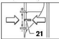
Bctanohobt ctyinactyntop 10 Ha haHHKm Ctyinb; ctyinactyntop Mae BiyTHO 3aHTN B3aepenHn.
BIDycttbTbHHT-bapAHHK HaOBmexyBaHITAN6HHN14, 06OBmexyBaHIN6HHN15MIRiABHOpecyBAtnca.
-Ппнсчть De6AOKyBaHbHnB BaxiAb 22 DOH37a TpIbHbO ONyCnAite Φe3epHnB BepCTAT DOH37, TOKNФpe3a 7 He TopKHTbcra NOBExPi6oPbAIOBaHO MATEpiAd.3HOBy BiNTcTb De6AOKyBaHbHn BaxiAb 22,1063adikcybaTHIO TaHbHHy 3aHpyEHH.
-ПИNTCHITbOBMeKByaBraHbHHBn315,IO6BINCIBHa cyTINHAcCTHnIpyo10.BCTAHOBITbABNKKO3aDONOMTOIO IHdEKCHOITIO3HaCKu16BTOAOXeHHRAOHOHnHnHn Hpe3epyBaHH18.
BCTAHOBITbOBmexyBaHn6HH15Ha6aKaHyrH6HHpy3epyBaHnTa3aTnHtBnHT-6apauHKHaOBmexyBaHn6HH14.CaIxKyte3A Tm,06HeNOCYHYTNABKOK3INAEKCHOIO3HOAHOIO 16.
HaTNCHTb HaDe6AOKyBaHbN BaxiB 22 Ta NiHIMITb Fpe3epHb BEpCTa Y HauHnue IIOKHeHH.
IpiBBeAiknI rAn6HnI ppe3epyBaHHa peKOMeHyctbca 3dCHOBaTH o6p6ky B dKa 3axoDIB, 3HIMAOU KOKHN 1a3 nTPOxy MaTePIAY. 3a DOnOMoHO CTpyHactO rYnpa 10 BN MoKeTe P03dAIHTN OTePAuIO ppe3epyBaHHa Ha dEklbKa eTANB. dA uTOBO BCTAOHbIT CTpyHactr YNPa HnnHckn I a6baHO Ia6hHo I a6hHnI ppe3i OpeauII o6p6kn CToaATKy HA BnOmy pBIHI. BiACTAH MIX pIBHMMOxHa 3MIHOAt, NOBepaOIO NcTpyBaBH1 TBnHTN 11.
TICIAI PIO6HOrO FOpe3epyBaHHB BuMOeTe IOBeTpAHHM IOBOPOTHOIpyKIN20 BCTAHOBHTIAN6HHy FOpe3epyBaHH TOHO HbA6KaHHPiBHe; DA 36IaBueHHI AN6HHI FOpe3epyBaHH NOBepTAE pyKHy 3a CTPIAKO ITOAHHHKA, AAM 3MeHHeHHI AN6HHI FOpe3epyBaHH NoBepTAE pyKHy IPOTH CTPIAHI OToHHHKA. UkaA19 CAYrE opiHTaII. 3a ODH ObEP TILnHA FOpe3epyBaHH 3MIHOCTbHa Ha 2,0 MM, KOKHa 3IQAIOK HA BEPxHBOMy KpAO IIaONiAe 0,1 MM. MakcHMaJIbHH dIana3OH peryAOBAHH CTAOHBt
± 8MM
HAnPKAAa:BakahA Tm6BnHa fpe3epyBAHHr CTAHOBtB 10,0 MM, npn Ipo6Hom ype3epyBAHHi Tm6nHa fpe3epyBAHHr CTAHOBnA 9,6 MM.
-ⅡHIMITb φpe3epHH BepCTaI iNkAldit, Hap., tpxn AepEBHHI IINIaNTy KO3aHH9, 106 φpe3a 7 pIn OYcKaHHI ToKpAAcR o6pOABoHAHO MATEPIAY. PHTCHITb BH3 Ae6OyBaBHn BaxiA 22 TaIOBIAHO OYcKaIIe φpe3epHH BepCTaDOHHY, POKI O6MekByaT RAN6HH 15 He cIe Ha CTynuactm ynp 10.
-Поверпьшkaу 19н«О»Та bДИСТБВHNT-бapaHuk 14.
POBEPHTb IOBOPOTy pyKHy 20 Ha 0,4 MM/4 IOIAJKH (pi3HHMIX3aAHMMiΦAKTHMH3HAeEHHM) i3aTRITb RBHHT-6apAHUK 14.
-ⅠepeBipTe Bm6paHy Fm6hHy fpe3epyBaHHa,3dHcHbHn 1ue OHe Tpo6he fpe3epyBaHHa.
TICAR BCTAHOBAEHHRAH6HINHΦpe3epyBaHH 6IaBHe 3MIHOHEIPOAOEHHARBKKKa 16 HA06MEKyaui HAN6HHN 15, ⅢO6 BN MOrn 3ABKAn 6aYHTHa 8KAI 18 TOTOHY RAN6HHy φpe3epyBaHH.
Bka3iBKn 1o0o po6oTH
3axnaiTe ppe3y BiIIOuTobXIB iYApib.
HannpMOKΦpe3epyBaHHraTonepauiΦpe3epyBaHHa (AMB.MaA.E)
Oepaiofpe3epybaHH Heo6xiaHO 3ABX43dHOBATnPOTn HAPPMKy 06eTAHN FpE3N7 (3ycptiueFpe3epybaHH).PiH ppe3epybaHHI 3a HAPPMKOM 06eTAHN (NONYTHe ppe3epybaHH) eAEKTPOPNHaA MOKe BHPBbHc3 pyk.
BCTAHOBITb6aKaHyIIm6HHyΦpe3epyBaHHA,INB.p03IA《HaCtpoBaHHraH6HHHΦpe3epyBaHHA
-ПнсаТБе eaktpponpma3 MHTOBaHOIO ppe30IO AO 6po6oBOaHOrO MaTePiaAY Ta yBIMKHITb eaktpponpmaA.
-ПИТМСИТБДБАКУВALEBHI BAKIAB22DOH3Y Ta NOIIAHOBONYCKAITEФpe3epHHBepCTaT,OKH He6yde DOCAHYTA BCTAHOBVAHA TANBINA HФpe3epYBAHNA.3HOBY
142|Ykpaɪhcbka
BIDTYbde6AOKyBaHnBaxiB22,063aikcyBatn 100rHMHy3aHpyehn.
-3dInchIOHTpeepyBaHHaPbHOMipHOIOIoo
-ⅡIcA3aKInHHeHnOeapuiIfpe3epyBaHHn3HOBy BCTAHOBITb fpe3epHnBepCTaYHaBHnue NOAOxEHn.
-BHMKHITb eAeKtpoPnPAaA.
Φe3epyBaHHH 3doaTkoBm yItoPOM (AHB.MaF)
AABOB60KBNBANKXDETAHAp..,PnPHpE3epyBaHHI
T3i8,BHMOXETe3AKPINTHHaOB6OBAaBHINDETAALDOUKY
a6o pekyBRAOKCTOAOATKOBOYUynopaTaBOHTNΦpe3epHM
BEPCTATOMy3AOBKDOATKOBOYUynopa.BOITbΦpe3epHM
BEPCTATOM3IOCKOR6OkyIANTKNKOB3AHHHy3AOBX
DOAtKOBOYUynopa.
KpomKOBe a6o npofoiabhe fpe3epyBaHHa
PnKpOMKOBOmy a60 IpoΦiABHOmy fpe3epyBaHHI 6e3
IAPAeAIBHOYtOpa p4e3y Heo6XiHO 6aAHaTHn
HAPPMHOUaFOIO a60 WApHKOTIDWHINKOM.
IiBdEItbYBMIXHEnEeKTpOpiPnAa360kyo 06p06IAOBAAHOI detaAI,uO6 HaprrmaHaIaIa6o 卅PAHKONIADWHTNHKΦe3N pTNArABdo KpAIO 06p06IAOBAAHOI detaAI.
-AbOMa pykAMn BeIt bIeKPTPOHnAA yADOBK KPMKN 06pOBAaBHOI DetAa. CAIkyte3 aTm, Uo6 36epirAtn PnRMN Kyt.3aHaTO CMHe HATNCKyBaHnMOKe NIOXKOADTH KPMOKy O6pOABAOBHOI DetAa.
Φe3epyBaHH 3 npaalebHm ynopom (nB.Ma.G)
BCTPOMITI IAPAAEhHbYIOT 29 HAPRMHMN CTPHXHMM 30 B OTOPHY TANTY 12 IATHCHTIb IROI BIAIOBIHMM UHOM 3a DIOIMOORO TBHNTIB-6apAHKIB 5.3aDIOIMOROI TBHNTIB-6apAHKIB 31 Ta 32 Bn MOXeTe OdoTKOBO BIDPERyIobATH DOBXHHI PIIAPAAEhHO YIOPA.
3aDIOIMOrOIOIOBOPOTHOpyKN33BnMOKTe, BIDNYCTHBUNOH6bA FBHHTN-BapAHUHNK31,TOHO HACTPOIN D0BXHHI.PINUBOMY3aODINOBePToDBXnHaMIHETBCHa 2.0MM,KOKHAIOIAKAHaIOBOPOTHIpyu33BIITOBiAc 0.1MM.
3adoTOMOHOYnpHOIIaHKn 34BmOxMeTe MInHTN efeKTNBHy OTOpHy NIOBepXHIO TapaAeIbHoro Ytopa.
BoBtBybIMKHEHM EAEKTOPTPOINLAADOM Y3AOB8K KpAIO 6Op6LBOHORO MATEPIAY 3 PIBOHMIHOI NOaueho, HATNCKUY30KNY HApaaNEAHBHyTnOP
PnIpΦe3epyBaHHI ⅢnapaAeBbHM yTOPOm 29 BiAcMOKTyBaTH mA/CTpyKxy CAd, YpeE3 CNEUaBbHIN BiACMOKTyBaAHn aAaITET 35. BiCmOKTyBaHn aAaITET 27 MoKH He 3HIMATN.
Φe3epyBaHHaHHTpMaHOU WnHOIO (AHB.MaA.I)
3aDIOOMOIOHOHnPMAHOI 43BMOKTe BHKOHyBaTHnpMOAIHIHpO60N.
AaKOMTeHcaui pi3Hui y BnCOTi Bam Tpe6a MOHTyBaTH npomixHyANTy42.
MOHTyIeΦpe3epHnUpKyA/b/aadTepHaPpMHOIuHHN 36, RIKTOKA3aHO HA MaIOHKY.
3aKPIITb HAPPMHUY 433a DOTOMORIO ODAHHX 3ATNCKHHX PnCTPOIB, HAPPNKAAD, CTpybHHH, Ha 06pOABaBbHJdAeJI. IpnCTABTe eAEKTPoPnAA3 MOHTOBAHMM aADIITepom HAPPMHOI UHHN 36do HAPPMHOI UHHN.
Φe3epyBaHH3 KONiPHO rIb3OIO (ANB.MaA.K-N)
3aOIOOMORIO KONIPHOI Rb3H 47MOKHapepeHOCHTHA
60p6oIAOBAHi DeTAl KOHTyPn Apa3kIB Ta a6AOHB.
AABHKOPNCaHHKoPioHOIiB3N47CIOaHTkyTpe6a BCTpOMTHaADITeKoPioHOIiB3N44BnNTyKO3AHH9.
BCTaHOIBa aadTep konipHOI rih34 38epxy HAHTy
KoBH3AH9 Ta npiPKpyITb Hro2 kpiHbHHM RBHTAMn 45.
CAdKyHe 3a THM, u6e6AkoBaBbHN BaxiAb d aad aadTepa
kOHPoRIOr34 BiABHo nepeCyBABc.
BCTAHOBiB TnDAtHy KOnIPHy RiA3y B 3aekHOcti BIA TOUHHN Hua6o 3pa3ka. YpeE 3BHTyaOuy BHCOTY KOnIPHOI rAB3NI MIIImAbaH ToBuHN Ha 6aOHaIOBHHA CKAADATB MM.
HaTCHiTB Ha 6bKOyBaBHH BaxiB 46 Ta BCTPOMITb KOnjHpyIa3by 47 3n3y B aAANTep KOnjPHoi Ria3N 44. PnI bOmy KOoBOaHi KyaauKIOBHH BiAYTHO 3aHTN y 3aHTeAAHBNB I pOPI3AX.
AiametpΦpe3Ma6 6yTH MeuHn 3a BHytpiHni AiametpKoipHOriA3H.
IIIOB BIACTAH BIA EHTPY DpEeN AO KPAO KOPIHOI Ia3b IOBCIOH bya OHAHKOBO, 3a HeoXbIOHOCTO KIPHYI b3y Ta IATNY BOK3AHMOKH BIAUHTPYBATHO AHOHOI
- PnHnCHtB De6oKyBaIhBn BaxIa 22 DOHIy Ta OYCTIb Fpe3epHn BEpCTA D0 YOUP y HAPPMKy ONOPHOI nHTN 12.3HOBy BiPyTcTB De6oKyBaIhBn BaxIa 22,IO6 3aikcBYATU QI FM6HNY 3AHyPeHHJ.
-ПОВИСТУ BKNKPYITB TBNHTH 3 IOTAIHOI ROAOBKOKO 49. BKPYITTBHNTH 3 UNAHDPNUHOI ROAOBKOKO 48B TEpeBaCheni DA HIX OTBOPN, UO6 PANTA KOB3AHH9 BIAHOb TpeCyBAaAC.
BCTpOMITb CEHTpyBaIbHy OIPaBky 50, RIK NOKa3HO HA MAIOHKY, y 3ATNCKAPO6OFO ICHPTyMeHTA.3aTIRHtB pyKO HAKINY RAky, IO6 CEHTpyBaIbHa OIPaBky MOIA BIAHBO COBATHC.
BnpiBnHte cHTpyBaIbHy onpABky 50 Ta KOniPy rIb3y 47 OHa Do OAnHO, TPOX INepeCyBaIOH NtMy KO3AHH9.
MiH03aTARHHTb rBHTN 3UAAHAPnHOOrOABKOIO48.

Romània | 143
BHTHITbIeHTpyBaAHyOppaKy50i3aTHCKaHa p6o4oHOHCPTpymHeTa.
HaTNCHTb HaAe6AOkyBaHbN BaxiB 22 Ta TiiAHIMtB fpe3epHb BEpCTaY hauHnue IIOAOxHeHH.
Φe3epyBaHHA 3 KONIPHOIO rIaB3OIO 47 3dINCHIOHTHACTYTHM YIHOM:
-ⅡAeBtIb yBIMKHeHn eAekTpPnPaA3 KOIpHOIO rIb30O 10wa6AoHy.
-PPNTCHITbAe6oKyBaHbHNBaxiAb22OHOH3yTa NOIaHbO OYcKaHTe Ppe3epnH BepCTaT,POKHe 6yAd OOCRAHYTA BCTAHOBHa TANbHa Ppe3epyBaHH.3HOBy BAtNyCTb Ae6oKyBaHbHN BaxiAB22,IO63aDfikCyBatN IO TANbHy 3aHpyHH.
-BeAeKToPnna3BnCTyNaOIO KOnPiHOIO Ib3oO y3doXIa6IoN, npHtncKyOuO 360ky.
Texhiue 06cAyroBbAHHa i cepBic
Texhihe 06cayrobyBaHHi oHneHH
Tepe6yab-kaHMMAHInyAuaRMn3eAEKtpponpAA DOMBHTHRHtBWTENCEAB3POSETKN.
106 eaeKtpnpnaaI npaioBaaikicho i haidiHo, TpmaTe pnaaia I BEHTnauuHIO TBOPb B NCTOTi.
B E kctpeMaIbHx yMoBaX 3actocyBaHHa 3a MOKANBICTO 3ABXAn BHKOPNCTOBYte BICMOKTYBaHbHnPiNCTPI. YACTo IPOADyBaHTe BEHTAunH iUAnH Ta TIAcEHyTe PnHaA Upe3 PnHCTPI 3axHCHO BHMKHeHH. PtN O6pO6uMetaIB YcepeAHNI eAEKTPoPnHaA DOMe OciDat H eAEKTPoPBOHdHN. Lc Moe KIOHaHTNC Ha 3axNCHI I0AJI eAEKTPoPnHaA.
KUTOpe6aIOMINHTNIADHYBAHbNKnKa6eB,ue Tpe6a poBHTHaipMI Bosch a6o B cepBicHI MaICTePHI DA eEAEKPTPOHCTPymETIB Bosch,0O6yHNKHyTN He63NEK.
JaHIO HeBbAIOUH NapeTeAlbHy TexHOIIO BHOToBAAHH IepeBIKIN PnPAH BcT-AkTN BnHEe 3AaY, HTOPEMOHT AO3BOAEbBCRA BHOKOBaTH NIIIBe ABTOP3OBAH i cepBCHM MaCTepHI DAeEAEKTPoPnAAID Bosch.
IpnBICx3aHnTahHnxipn3aMOBaHHe3aHactHH,6yAbaacka,0oB'3KoBO 3a3HaJaTe 1O-3HaunHmTObapHH HOMep,io 3hAxoHbTcRa Ha 3abOcbkTi Ta6AnuCi eEeKTopPnAAyD.
Cepbicha Maimctepnio6cayrobyBaHHKaieHtB
B cepbichm MaHCTephi Bn OTPMaTe BiADOBa Ha Bauii 3aHTANHTHCTOCBNO pEMOHTy I TEXHHORO 6cAryROBYaHHaBATOIPOdykTy.MaIOHNK B AETARx IHFOpMAuio 3aTtAcTHM MoXHa 3aApecoIO: www.bosch-pt.com
KOHcybTaHTBosch3paJcTIO doTOMOxyTB Bam pH 3aHTAHIX CTOCBOH KytIBa,3actocybaHH iHaaraoXeHHI IpyoayH INPAAAADHOHX.
IapaHTHe 06cayrobyBaHH i pemOH tEAEKtpoHCTpyMeHTy 3aIHIOOTbC BIAIOBIOHO BIMOI I HOPM BIFOTOBAOBaHa TepHToPi BCx KAIH MwE y DIPMOBX aBO abTOP3OBaHX cepBICN CEHTPAX dipmN P06ept 5oW).
IIOPEPAKHH! BkOpNCTAHH KOHpAkaTHO IPOAdykuII H6e3nneB E KcNpTaataiu I MOKe MATN HERATNBH I HAICAI NAR 3AOOB' BTOROBAAHIN PO3NOBCIAKHeKOHtPakTHIO PNOAkyIpeCaIyETb3a3AKOHOMB AAMHcTpaTHBOHYI KPMHaABHOHYTOPAKY.
ykpaiHa
TOB «PobepT Boiu»
CepBicHHIeHTp eAekTpoHCTpyMeHTIB
By. KpaHr, 1,02660, KIB-60
YkpaHa
TeA:+38(044)4902407(6araTOKaHaBHH)
E-Mail: pt-service.ua@bosch.com
OphiuiHn caH: www.bosch-powertools.com.ua
Apeca PeriohBnHrnapHTINHX CepBICHNx MaIcTepeHb3a-3haeHa B HauioHbHOMy rapaHTINHO MyaONi.
Ytmaiaui
EeKTPoPnPAaH, npMaAaI yIyakOBky Tpe6a 3aBAHT Ha eKoIorIHNo HCTy NIOBTOHy nepeO6ky.
He BnKnDaIte eAeKToiHCTpyMeHTN bIObYToBe cMITTA!
Aaie aKpH EC:
BIAIOBAHO AO EBPOIeNcKoI HnpeKTHBN 2002/96/EC IPO BIAIPAuBaOHaI eAeKToP-i eAeKTOHHI PIIAAH I IIIEpTBOpEHNR B HAIOHAOBMY3AKOHDACTBI eAEKTOPIHAAAD,IO BHNAM 3BXNAHNR, IOBNNHI 3DABATHCOKPeM0I YTHAIyBAHTHC EKOALFOHNO CHTMC NTOCOCOM.
Moxambi 3miH.
Româna
Instructiuni privind siguranta si protectia muncii
Senior Vice President
Engineering
Dr. Eckerhard Strötgen
Engineering Director
PT/ESI
Paa
Robert Bosch GmbH, Power Tools Division
D-70745 Leinfelden-Echterdingen
26.10.2011
Montare
IpeHa3NaeHHe Ha eAekTpOnHCTpyMeHTa
ELeKTPoHnCTpyMeHTbTeIpeHa3Haueh 3aΦpe3OBAHe Ipn
H3IOA3BaHe HbTbPDA OCHOBA Ha KaHAA, pb6OBe, IpOΦHH
IpOaBraTH OTBOpH, KaTO H a KOINPHoΦpe3OBA He
AbpBecNH MaTePAH, PAACTMaC a Aekn CTPOHTAHM
MaTePAH.
IpnIOHIXeHaCKoPcHa BbPTHe N CIOAOAun Ppe3epn MoTAt Da6bDatobpa60TaBnH CbuO N CBETHN MetaAn.
H306pa3eHH eAeMeHTn
HomepnpaHToHa elememntHe aeKtpOnHCTpymEnTa Ce OTHACo H3O6paXeHHa Ta CtpaHHTe C pHyprte.
1AchaPbKOxBaTka(M3oHpaHaIOBbpxHOCT3a 3axBaIaHe)
23actopopbaa6ytoh3aynckOBnIpeKcbBa
3IOTeHUMoMeTpB3aIIpeAdbapnTeAenH3bOpHaCKopocTtHa BbPteHe
4Aoc3a3actoTnOPBaHeHaBa
5 BnHT C kPnAATA Tnaba 3a IIINCIOcO6aENHETO 3a YcIIOpeAHO BOAEHe (2x)*
6Ipea3eHekpan
7Φpe3ep
8OTBOPHaHnPaBAHbUHTe HaHnHa TINCIOO6AEMETO 3aYCTOpeAHO BDOHe
9AHTnΦpHKUHNOHnIaOua
10CTeTeHeHOrpaHmHTeA
11 PeryaHpaun BHTOBe 3aCTeEHnOrpaHnTeA
12 OchoBHaTMOOa
133aunTeH MaHIOH
14 BnHt C kPnAuta rAba 3a perynpaHe Ha db6OuHHNOrpAHnHTeA
15Ab60HHHeHOrpaHHHTeA
16Паьзагс Маркнровka
17Aba pboKoBbTaKa (H3OHa HIOBbpxHOCT 3a 3aBAaHa)
18 Ckaa 3a peryinahe Ha dba60nHaTa Ha ppe3oBaHe
19 Ckaa 3a dno perynpahe Ha db60nHata Ha de30baHe
20Bbpttaa ce pkoxbatka 3a fHOppeyIpahe Ha db6ouhata Ha fpe3oBaHe
21MapKpOBKa3aHpaBnBaHeHaHyEeBaTaTOUka
22 De6knpaaoc
23Kpnnuata raikacuaHa
24IyckOBIpeKbcBaY
25FauehenKAnou 24mm
26 Mapky 3a npaxoyaaBHe (0 35 mm)
27AaTep3aacnnpauHnHa ype6a
28 BnHc HnAteHa rAba 3a aAaIepa 3a IpaXoyAABHe (2x)
29 Pnncno6aHHe 3a yCtopeAHO BOaHe
30 Hapabaaa 3a Taipncoc6eHMeTo 3a yctopeHO BOeHE (2x)
31 BnHt C KPNaTa Taa 3a CFnHO peryInpaHe Ha npCTIOcO6AeHNeto 3a ycTOpEHO BOeHE (2x)
32 BnHt C kPnAyata rAaba 3a rpy6o peryAmpaHe Ha PnCIO6bAeHMeTo 3a ycIopeAHO BOeHe (2x)
33 BytoH 3a fHIO peryAmpaHe Ha npCnOco6AeHHeto 3a yctopeAHO BOeHe
34Perynpyema onopha shna 3a npncno6aeHHeTo 3a ycnpoeAHO BOEHE
35 AaTep 3a TpaxoyAaBHe Ha OTopata 3a yCtopeHo BOeHE
36 PnncocobHe 3a ppe3oBaHne KpbroBa AbaAanTep 3a HappabAAaaata HnHa
37 PboKOBaKaHa IIpHcIOcO6eHHeTO 3aΦpe3ObaHe NO KpbFOBa △bTa
38 BnT C kPnAa T rAba 3a rpy6o pyympaHn H npncno6aeHnTo 3a qpe30BaHe I KpbroBa Dra (2x)
39 BHT C KPNHATA TAABA 3a FINHO peryHpaH a H PnCnTOcO6AeHHeTo 3a FpE3ObaHe To KpbroBa Abla (1x)*
40Bbptnla ce pkoxaTka 3a fnopeypane Ha npncnoc6AenHTo 3a pfpeoBaHe IIO KpbroBa Dra
41 CEHTPnpaa BnHt 3a PnCTIOco6AeHHeTo 3aΦpe3OBAHe NO KpbTOBa DaTa
42AHTAHIOHOHHAIOOa(BKMOOeHa BOKOMTAEKTOBKaTaHa IpncTOc06aeHHeto3a ppe3oBaHe TPOKpbroBaDba)
43HnpaBAABaAa 1
44SDS-aanTep3aKoTmpaIaBtYka
453actonopBaBnHT 3a aadTepa Ha KOINpaata BtYkA (2x)

154|Быагарский
46 Aoc3a ocbo6oxdaBaHe Ha aadantepaHa KOnnpaaata BTyKa
47KoNnpaaaBtyaKa
48 BnHT C uHmHdpnHa rAaBa 3a aHTnDpHKuHOHaTa TAOHa
49BnHt Cb3eHKepeBaHa rAba 3a aHTnΦpNkUHOHHaT aOua
50LehtpobaaDopnHk
*H3o6pa3eHnTe Ha 0hrypnte H OTHcaHnTe AOHTBAHNTeHH
IpcHCTOCO6aHHe CA BKAUQEHN B CTAHdAPTHa OKOMTAeKTOBkA
Ha ypeAa. H3uepeTateHnCTbcbKa H AOHTBAHNTeHH
IpcHCTOCO6aHnMeKOTeAa HAMEPHe CbOTBEHO B KATAaORA Hn 3a
AOHTBAHNTeHH IpcHCTOCO6aHHe.
TexHHueckn daHHN
| Оberprüche GOF 900 CE | |||
| Professional | GOF 1300 CE Professional | ||
| Кataхожен Homep | 0 601 614 6.. 0 601 613 6.. | ||
| HominnaHa KoncymrupaHa MoiHocT | W | 9 | 0 |
| Скорост Ha BbptHe Na ПраЗен XoA | min-1 | 12000 - 24000 | 12000 - 24000 |
| Пребарптелен ИЗБор Ha СкоростТа Ha BbptHe | ● | ● | |
| Мода за Тадьржale Ha Тостогнha Скорost Ha BbptHe | ● | ● | |
| Вьзмохноct 3a Вл�чыане Ha acntimaонна систema | ● | ● | |
| Гиздд за равOTEN ИНСТРУМЕТ | mm | 6 - 8 | 6 - 12,7 |
| Инчовe | ½ | ½ - ½ | |
| XoA Ha Фразозваша Тлава | mm 50 58 | ||
| Маса CBлаласно EPTA-Procedure 01/2003 | kg 3,5 4,8 | ||
| Клac Ha Заша | ☐/II /II | ☐ | |
AHHHTTE Ce 0AHTCT DO HMOHHAHO HAPTEXEHNE [U] 230 V. PnI pa3AAHHO HAPTEXEHNE, KAIO I pIIN CTEIIHAAHITE KTHAI HEN 3A HIKON CTPAHN AHHNTTE MORAT Da CPOAANABAT.
MoA, 06bPheE BnMaHHe Ha kataoXHHa HOpH a BaIIra eAeKTPOHCTpyMeHt, HAIICAH Ha Tabekkata My. TbpiOBckHTe HAMMeHOBAHr Ha HAKOeAEKTPOHCTpyMeHTn MoTat Da bBdT pPOMeHn.
HΦopmaJHa3a3b4BaHwMnBn6paun
CTOHIOHTNE3aWymacnpeaeHcBbACHOEN60745.
PabHHIeToAHaReHepnapHHaWmO6NkHOBeHo e:paBHHe Ha3ByKOBOTaHaRAhaE89dB(A);MOuHocHTa3Byka
100dB(A).HeonpeAeHocTK=3dB.
Pa6oTeC uymo3aIayuHTeAN!
PbHata CTOIOHCT Ha B6paunHTe a (BektOPHATA cyma TIO TPHe HapRaAe Hn HeOppeAeHEoCTTa K ca OPepeAeHn cbFaCHO EN 60745:
a_h = 5,5m / s,K = 2,5m / s^2
PabHnIeTo Ha rHeeppaHHTe Bn6paun, IocOeHO B ToBa PbkBOAOCTBO 3a EKcNIOaTauIN, eOpTepeAeHO CbIaCHo IpoueApATA, AeHHnHPaB EN 60745, H MoKe Da 6bDe NtIOA3BAHO 3a CpaBnBAe C apTy IN eAeKTPOnHCTpyMeHTN. To eNOXoAIO cBo h 3a IpeDbapNTeHa OPHeHTPOBbHa TpEneHc HA HOBAPBaHETO OT Bn6paun.
ItocoueHOTo HHOBa hreepnpanHe Bn6paunie
IpeCTaBHTeHO 3a Hau-ueTo CpeUAnHe TpNLOKeHNHa
eaeKTOPOHCTpyMeHTA. Bce NaK, Ako AEeKTOPHCTpyMeHTb Ce
HIOA3Ba 3a DpyIn DeHOCTH, CdpYn paOToHHNCHPTyMeHTn
HnA KO He bDeNoDbPxAk, KaTTo ePiPeDnCaHo, paBHNiEto
Ha reepnpanHe Bn6paunno M0ke Da c IpomEnu. Toba 6n
MOnAo Da yBeAHmN 3hAnHTeHO CymaHTo HAtOBapBAe OTHB6paunn B IpoceHa paOba.
3aToHnata TpeueKHa HatoBapBaHETO Bn6paunTp8Ba Da 6b4aT B3HMAnH TpeBDAH INEPHOANTE, B KONTO
eAEKPOHHTPYMHTbTe E3KAUQEH HANpaBOTN,HOHeCEIa3BA.ToBxaMOA3HaHTeHAnDaHaMaAHcymHOTHOHATOBAPBAOETB6paHIN.
IpeINCBaHTe DoTbAHHTeHm MepK3a TpeTa3BaHe Ha paB0TeuH C eEeKTPoHNCTpymHTe OT Bb3AeHCTBnTo HA Bn6paHInTe, HapnIMep:TexHHuecko 0cClykBaHe Ha eEeKTPoHNCTpymTeHa paB0THTE HnCTpyMeHTn, IOdaPbXaHe Ha PbETe ToTlAn, ceaeCbO6paHa oprAHHaau Ha paB0THTE CTbIK.
Aeknapa3a cboTBcTBn

CITbHa OTOBOPHOCT HHe DEKApHpAme, YEOTINCAHNRTB 《TEXHHNECKH DAHHNIPPOADYKT CBOBTETCTBA HCAEHNHTe CTaHAPTN HAN HOpMaTHBHN DOKMeHTN: EN 60745 cbTAACHO N3HKCBAHNTHa HAnpeKTHBN 2011/65/EC, 2004/108/EO, 2006/42/EO.
TexHHuecka DOKUMeHTaUN (2006/42/EO) npH: Robert Bosch GmbH, PT/ETM9.
D-70745 Leinfelden-Echterdingen
Dr. Egbert Schneider Dr. Eckerhard Strötgen
Senior Vice President Engineering Director Engineering PT/ESI
ppa. 1000 i.v. nuOycu
Robert Bosch GmbH, Power Tools Division D-70745 Leinfelden-Echterdingen
26.10.2011


BbIrapckm|155
MOnTHupaHe
IIOCTABAHe Ha pa60THnH NCHpymENT (BHXTeΦn.A)
IpeHnK3BbpuBaHa N KaKBrTo H Da e DeHocTH TPOeKtPOHnHCTpyMeHTaN K3AIOuBaTte UeNCeAOT 3axpaHbauTa MPexa.
PnIOCTABAHHe HCMHnHa pa60THMa HnCHTpymEnCe npenopbUba Da pa6OHTe C ppea3HH PbKaBnH.
B3aBNCMHOCTOT KOHNKpeTHO H3TbHABHaHaTa DeHHOCCTMOXETe
daHIOA3BaTeΦpeepnCpa3ANHO H3TbAHHeHnC
pa3ANHO KaucctBO.
Φpe3epn OT 6bp30ep3Ha CTOMaHa Ca IIOXO4AUN 3a 6opabotbaHe Meku MaTepHaH, HAp. MeKa DpBecHn H TAACTMCH.
PpeepnTbBpOCTaBmTTAactHHCaCteuHaHO InpaHa3NaueHEn 3a TBpDn A6pa3NBn MaTepnAaN Kato TBpdaDbpeCnHa N aMyMNHN.
OpHnHaAN Hpe3epn 06rataTApoH3BOADtBEHa rama Ha Boi 3a OToBbAHNTEAHN IpnCIOcO6eHHa MoKeTe HAmePeHTe npin Baan TBPROE.
H3no3BaIte cAmO uCTn Dpeepn B 6e3yKoPn CbCToHHe.
-3aBpTeTpeDnA3HnE ekpaH 6HaOy.
3aBbPTeAocTa 3a6oKpHaHeBaIa4noNocKaHa YACOBHKOBATAcpeKAHnO3aDpXteTAKa(0).TPIH HEo6xoAMOC3aBbPTeAeKOBAHaEAEKTPOABHrTeA, AOKATO B6aeOkPAH.
Pa3BnTeXoAeHApObTa rAka 23 CraeHnna KIOU 25 (pa3Mep 24 mm)upea3abpTaHe BTOcoka,obpaTHa Ha HacOBHNKBaTcPEKa()
-BkapaIte pfpe3epa BcaHrata. ONaWKATA ha pfpe3epa TpaBa da 6bde BkapaHa HauMaKo Ha 20 mm B cHrata.
3AteHETeXoAeHApobataTajka23craeHnnaKIOUy 25 (pa3Mep 24 mm)upe33abptane no nocoka Ha cAOBHHKOBA tCTpeKa.OTtYMeTe NOCTa 3a bOknpaHe HA BaHa AeEKePTOHCPmTeMA 4.
3aBpTeIpeIa3HnEkpan6Harope.
He noctabnIe fpe3epn C dAmetbp,TO-0AMOT 50mm6e3 konnpa BtykA. TaKbBa fpe3epn He Moarat Da MHAT TIPe OCHOBHATA TIOOyA.
He 3aTnraIte XoLHeApobata raiKa Ha zHaRata 3dPabO, Ako He mOHTnpaH pIe3ep. B IpTOHbEN Cauy aI cHaTnata MOKE daBbE TopeBaDEHa.
CnCTema 3a npaxoylaBHe (BNXte nR.B)
PpaxoBe,OTeAaHcNcpeHnO6paB0BaHetoHaMATEpHAA KATO CbDpKJauu OAOBO 60H,NKOH BNODBeBpBecHna MHepaAHmMeTAAMorTa 6bDaTOnACHn3a3pABeTO. KOHTAKTBTOKoKoHnBAIMBuaBaHToHaTKBaPbOeMOrTDA pEaHnB3NKAT aAEPrHnPeakuHn H/Am 3a6oJIbAHnHa dXAteAHnTe bTbTuHa Ha paBoTeuHa c EAEKTPoHnCTpyEmHa HnHAMHpauHcCe h6An3O Anu. OnpeDeAEHNpaxoBe,Hapr.OTeAaHnTe ce pInp 6pa60TaBaHe Hb6yKnDb6,cCHTAT3KaHcpePOReHHN, OOC6EHO B KOMbHauHnC XMMKnAa3TpeTpNaHa He AApBecHna (xPomat,KOHcePBaTHnHAp.) .DOnycka Ce
06pabotbAHEToHa CbApxaun a36ct MATEPAH cAmOOTcBtBtHO 06yehn KBaMnnpaHn nua.
IIO B3MOXHOCT H3IOA3BAHTE IOXO4A7a 3a 06pa6oBtAHNA MATEHAA CNCTema 3a IpaXOyAABaHE.
OCHYPRABAITE DO60 PNOPOBETPABAHn pa60HTO MRCTO.
-Прелорьа CBинлбането HaДnxATEHa Macka CФИТБОТКАСР2.
CtaaBaeTBAaHbHTBeB BaaTAtCTPAHa3aKoHOBN pa3Tope6n,BaAaHNtpnO6pa80TaHe Ha cToBTHTMe MATePHa.
H36BBAHTHe HATpyTBAHe HaIpx HA pa60THOTMOCTO. PpaxbT MOXe AeCHO Da Ce CAMOBb3TAAmeHH.
MOHTIPAHE Ha aadTepa 3a npaxoyabHHe
AaANTepb3a paxoyAABHe 27 MoKe Da 6bDe MOHTpAH TaKa, ye IaHbT Da 6bDe HBeDEH HAppe Hn Ha3aA. Ako ue 3IOA3Bate a aIITep 3a KOHTpaa BtYka 44 MoKe Da CE HAOKx DA FO MPHTPATE 3abbpTHn Ha 180°, 3a Da He OAnHa aIaIETpe 3a paxoyAABHe 27 Do AOCTa 3a OCBO6OABAHe 46. PIn MOHTpHae C N3BExEHa De HAHaTn HAPpeA PteABapTEHNO Tp6Ba Da 6bde EMOTHPaH PpeDn3HHr EpkAH 6. 3actoIopete a aIantepa 3a paxoyAABHe 27 KbM OCHOBHATA IIOVA C ABATA BHNTA 28 C HAKATEHa IaBA 12.
BkauBaHe Ha actnpaunohHa Cnctama
BkIoueTe Mapkyua Ha actnpaunHna ype6a/ npaxocmykaHa (0 35 mm) 26 (OtohHnTEHO npHCIOcO6AEHe) KbM MOHTnPAHHa aadTep. CbPxete Mapkyua 26 c PpaxOCMykaHa (OtohHnTEHO npCTOC6AEHe).
EAEKTPOHNCTPymEtBbMxAaBbAIOueH HEOCEpACTBEHO KMB KOHTAKTa HA YNHIBePCAAHa
tpaxOCMyKaKaHa BA BOW C MOAY 3a AHCtAHUHOHO
3aEDCTBaHE. PnH CTAPTHPAHo Ha EAEKTPOHCTPymTeA
ABOTMAHNO 3aONBA DA pa60TH INpaxOCMyKaKATA.
HIOBAHATA pAXOCMyKaKaTpa6BA Da e pINrOHa 3a
pa6oTAc6p6oTBAHN MATEpHa.
Ako npa 60b0ta ce otae ooc6eHo Bpeae 3a 3paBeto npax Hn KaHeporeHeH npax,H3IOA3BaIte CTeuHaH3npaHa npaxOcMykaKa.
MOHTnpaHHe HnpeIa3HHn ekpan (BHXTe nHr.C)
IOCTABETNE PpIaIIHNIKPAH 6 OTIPNE TAKA BbB BOADUHTE,ue 1a 6bde 3axbaHAT C pIeippaKaHE.3a DEMOTHPaHE 3axBaHETe O tBeTe CTpann I rHOIbPnTne HApED.
Pa6oTa c eAeKtpoHcTpymeHa
IyckaHe BekCTAataaHa
BHHMABaIe 3a HATPExEHNTo Ha 3axpaHbauata MPexaI HAPTEXEHnTo Ha 3axpaHbauata MPexa Tp8Ba Da CbOTBeTCTBa HA DAHNTE, NOCOeHN Ha Ta6ekAka HA eKtpoHHCTpymEnTA. YpeH, 0603HaueHN c 230 V, MORat Aa 6bDaT 3axpaHbAHn H C HATPExEHnE 220 V.
156|Быларскn
IpeBaPHTeAHO yCTAHOBRABaHe Ha CKOPoCTTa Ha Bbptene
CTOIEHUMOMEbpa3aIPIeBaPHTeAHOyCTAHOBBAHe HA CKOPOCTHa HbPTBEHE 3 MOKETe AaIMMEHARE CKOPOCTHa BbPTHE CbOpe3HO KOHKpTeHATA DeHoCT CBIO IO NIO BPMe Ha paOba.
1-2 HnckaCKopoCTHaBbPteHe
3-4 cpeHaCKOpocHa BbPteHe
5-6 BHCOKCACKOPCTHaBbPteHe
NOCOCHENTB TABAUATA CTOHOCTHCAOPHEHTPOBOBHHH Heo6xOAMATA CKOPCT HA BPTHE3ABCNOT O6p0BTBAHMA MATEPHANKOHKPHTHE PAOTHNY CVAOBINMOKEA DC OPENDEPAH4pe3H3P06BaHEHaNPAKTHKA.
| Матерпдаметр на | Фразер(a) (mm) | Позида на пotingу- metыра 3 |
| Тьрда дрвесни (бук) | 4-10 | 5-6 |
| 12-20 | 3-4 | |
| 22-40 | 1-2 | |
| Мека дрвесни (бор) | 4-10 | 5-6 |
| 12-20 | 3-6 | |
| 22-40 | 1-3 | |
| Шпэрпат | 4-10 | 3-6 |
| 12-20 | 2-4 | |
| 22-40 | 1-3 | |
| Пл actма ca | 4-15 | 2-3 |
| 16-40 | 1-2 | |
| Вальни | 4-15 | 1-2 |
| 16-40 | 1 |
CnaIPOaXHTeHa paOta C HnCKa CKOpCT Ha BbPteHE TpRbAa OXAaHtE EAEKTOPHNCTpyMEnTA, KATO 0 OCTabTe aPa botn Ha npae3x HoB II pOaXaXeHne Ipi6A. Ha 3 MmHyTHc MaKmMaHa CKOpCT Ha BbPteHE.
BkAIOUBAHe H3KAIOUBAHe
IpeAn BkmoBaHe HAcTpoTe Db60HnHaTa Ha Bp3BaHe, BKKe pa3eAa «PeynPaHe Ha Db60HnHaTa Ha Bp3BaHe
3aBKAIOUBAHe Ha eAeKPTPOHnCTpyMeHTa HATINCHETI 3aDpbXte TnyCKOBnI PpeKbCBaY 24.
3a3actonopbahe Ha HATCHAHITyCKOB IIpeKbCBa24 HATCHETe 6yTOHa 2.
3a N3KAAOVAHe Ha eAeKToPNHCTpyMeHTAOTyCHETe TnyCKBnpeKbCau 24, CbTOBeTHo Ako e SactOnepc H C BytoHa 2, MPBO HATChTE KpATKOTpaHIO H CaeTobA OTyCHETe NtCKOBnpeKbCau 24.
Moyn3aTOcTOnHa cKOpOCT Ha BbTpTeHe
EeKtPOHeH MoAyn IIOAdbPka CKOpocTHa HbBpTeHa Htpa3eH XoA N IOA HatoBapBaH pKaTnueckn TIOCTOHHA, C KOEt OCHyprBaIOCTOHHO O6pa IPOHNBOIMTeAHOCHT.
IIaBHO BKAIOUBaHe
EAEKTOPOHO YNPABHeAe 3aTnABHO BkAOUbaHe OpArHbUAA bPTIaMOMETITnCtAPtnaHe yBaENbAaBAOTOPAHOCHTHa EAeKTKPOABRfATEAe.
Perynpahe Haab60HHata Ha Bp3BaHe (BHXTe pHr.D)
Dorpycka c e peryhpaneta H a b60nHata h Bp3BaHe Aa Ce H3BbpuBa Ca mo KOrato eaeKtPOHHCTPmHtBe N3KIAOyen.
Ipy60perymaheHaab6oHHataHaBpa3BaHeceHbBpwaTOCAEDHHaAHH:
-IOCTABETe eAekTPOHnCTpymEnTa C MOHTpAHnA FOpeep Bbpxy 6pbabOTbAHnA Detai.
CpbkoxBatkataIOCTABETepnCTOCO6AHEHTo3aΦHOp epyanpae20PnHbMHTAEHOIPOcpeTATA.3aueTA 3aBbPTeE pKoXBtKaTAto20,DOKATO MapKnPOBKeTBe 21 3actahEHa CpeuyApTa,KaTOe IIOKA3aHo Ha fHrypTa.CaED TOBA3abPTe cKaAATA19doHyAEBa IO3HmIAO<0>
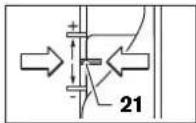
-NotCTABETeCTEHHTaONOPA10HAH-HNCKATACTENHE;CTETEHHTaOTOPAITINADABIO3NHCNAOTETAMBOPteppKaBaHe.
-PaBHHTE BnHTA C KpHuaTAt Raaba Ha bAoOpHHH 0rpaHHTe14, Taka yeAoBuOpHHHRT OPAHHHTe15 DA MOKe A Ce ABKn CB0ODoHO.
HaTNCHETe OCB60XdaBaaHnAoCT 22 HAOy NbABHO CNYCHETe 06epFpe3a HAOy,doKATO ppe3epb7 DOnpe 0o 6pa6oTBaHnA Detai.OTHOBO OTYCHETe OC60XdaBaaHnAoCT 22,3a Da 3actOpnpTe Ta3n DAb6OuHn Ha CTyCKaHe.
-ПИТИСHTЕДБАБОУHINHA ORPAHUNITEA15HaDOY,DOKATO DONPE DO CTENEHNOR OPAHUNITEA10.NOCTABETeNAb3raa CMAPKNIPOKATA16 HA PO3HUN《O》Ha CKaAata 3a ABaB6OuHATA NaФpe3OBAHe 18.
IocTabeTe AB60HHHnOrpaHHHTe 15 Ha KHeAHaTAt AB60HHa H aPc3OBAHe H aTeHReTe 3ApBO BnHTa C KpHnAaT a Tnaba 14.BHmAbae Ta He H3MeCTBaTe NObeYe Ib3raFa C MapKnPOBkata 16.
-HaTHCHETEOcBO6OxAaBauHIAoCTNIOBnHTe 06epoep3ata22BTOPAIO3nua.
TINI ROEMH Db6OuHH Ha Ppe3oBaHe Tp8b6a Da H3TBAHBATE HNKoKIO IPOXoDA CTO-MaKa Db6OuHHa HA Bp3BaHe. C NOMOHTA HA CTENEHNn ORPAHNHTE 10 MOKeTe da pa3aENeTIe Ppe3oBAHETO HA HNKoKIO CTbIKN. 3a eENTa HAcTPOTE XeAAHATA Db6oHHa HA Ppe3oBAe CHaH-NHCOTO CTbTAHO HA CTENEHNn ORPAHNHTE h CEA TOBt 3a TbPBNTE IPOXoAH36epete IO-BNCOKITE CTENEH. PazMeptHa CTbNAATA MOKE Da CE peryAmpa CBHTOBETE 11.
CaeIpi6H0Φpe3OBAHeMOKETeAHaHcTpOteDb6OuHnata HaΦpe3OBAHeTOH0HaJXeALHHaP3MePpe3aBbPtaHeHa pbKoXBtKaTa20;3aBBpTaHE NO TOCOKAHa YAcOBHnKBoTA CTPEKA BOHOYBEAMUBAHe HAb6OuHnATA HaΦpe3OBAHe,CbOTBTHO6bPAHOHa YAcOBHnKBoTA CTpeKa- 10 HAMAABaHE Ha b6OuHnAHaΦpe3oBAe. IPh peryApaHE MOKETeAHaHIOA3BATECKAATA19.EHN6OBOPT CbOTBETCTBaHA XODHa H3MecTBaHe2,0mm,EHOdAEHHeHa
BbIrapckn1 157
TROPHNAbKaAATA19Cb0TBETCTBaHaN3MeHHeHa
Ab6OHHATAHaΦpe3OBAeC0,1mm.MakcHMAHOTo
N3MeHHeHaBb6OHHATAHaΦpe3OBAe±8mm.
PnHMe:KeAHaTa db6OuHHa Ha ppe3oBaHe e 10,0 mm, n3MepeHaTa db6OuHHa PnPiPo6HTo ppe3oBaHe e 9,6 mm.
-10BAMHTeO6pe3aTnIOCTABETe IOA aHNTDPKINOHHTaN0a9OTNAPUNH Tpyieta,taKauePnCNYCAHe Ppe3ebT7AaHEoNIPA o6pObTOBAHHaTeaHa. HatCHTEcO6OkaabaunAoCTHOANy 22 H6ABHO CTYCHETeO6pe3aTAt,DOkato DAb6OuHHHOr OPARAHNTEA 15 OONPE AOCTeEHNNrOPAHNHTE 10
-3aBbPTe CkAATA 19 AO HyaEBA TIO3Hn H pa3BnTe BnHTa C KpHaTuTa TAABA 14.
3abbpTepebKoBAtkata 20noNtOcKaHaacOBHKnOBata CTpeKaHa0,4mm/4aeneHHa (pa3nKaTaMeMdy XeAaHATA HcEHTBHeTATA bdoOHnHa ppe3oBaHE) OTHOBO 3aTeHETBEHNTCA KPMNAATA rAba 14.
-Провете НоваТдббочинСпвсторно Прбнфpe30bahe.
CaeHaCTPOBaHe Haab6OuHnHa Ha Pfe3OBeHe IpOMeHNrOBoeYe PO3MnHTa HA Hb3ra4a 16 Ha ab6OuHHnOrpaHnHtE 15,3a MoKTe BnHarHa CkAaIa 18AaOTnHATE MOEHHTa AB6OuHnHa Bp3BaHe.
Yka3aHn 3pa60Ta
Ipea3BaIe ope3epa or yAapn pe3Kn HatoBapBaan.
TocokaHaΦpe3ObaHnΦpe3ObaHae(BHXTeΦHr.E)
Φe3ObaHETO p6Ba DA CE h3BbPbBA BHHAR nCpeuI TocOKa HbBPTEHe Hppe3epa7 I (n- nHa CpeUYTOAOXHTe ABHXENHa).PiH p3e3oBAHTo TocOKa HbBPTEHe Hppe3epa BB3HNKBAT ROAEM CHAH Hpaekua (OTKAT) NcbseCTByBa ONACOBCT Da H3TbPBETE eAEKTPONHCTpyMeHTA OT PbETe CN.
- YCTAOBETEJEAHATAbABOOHNAHBA BPR3BAHe, 3a eLTA BnKTe paaDeAePeryHpaH aBbAOOHATA ha BpRA3BaHe).
-ⅡOCTABETe eAekTPOHnCTpyMeHTa CMOHTpHaONpe3ep Bbpxo6pb0BtAHnTeaHnTOBkAIQHTe.
HATMCHETE OCB06OxAaUHn AOT 22 HAOy H6ABHO CNYCHTE oEBpe3aHa DAOy, AOKATO BAE AOCTHnHATA NaTOeHATA DaIOOHnHa BA Bp3BaHe. OTHOBO OTYCHETe OCB06OxAaUHn AOT 22 aD aactoNOpTe TaHn DAIOUHnHa cTcYcKaHe.
-Ⅱ3πbAHeTeΦpe3OBaHETo C IOCTOARHHO IIOaBaHe.
-CEAIIpHKIOUbaHe Ha IPOUca HaΦpe3OBAHe BbPheTe o6epe3aT BnH-roHa T03uHa.
-ⅢaIOHTe eAeKTPoHHCTpyMeHTa.
Φe3oBaHe c BoAeua OTopa (BnXTe ΦHrypa F)
PnO6pOBAHe HaToLEMDeTAAH,HaIp.PnPfpe3oBaHe HAJ6eOBe,MOKTeAa3KepiHTe KbM AETAAbCKa HN NOMUHa ONOpA Hd BOAnTE O6pePcEaTtno He.BoTeO6pePcEaT,KATO JOnHpate DO NOMouHata ONOpA bC cCKoeha TcPaHa haAtnDphKkuHOHHaTmoa.
Φe3oBaHe NaPb6OBe/Φe3oBaHe TnTpoΦHa
He h3xBbpaIte eAeKTPponHCTpyMeHTn pIn 6HTOBTe OTnabu
Cama 3a CtpannOT EC:

CbIaCHO EbponeNcKa dpeKTHBa 2002/96/EO OTHOCHO H3A3Aa OTyIOTpeBa eEeKTPueCKHa N EeKTPPOHAn APaTpya N yTBpbXABAHeto N KaTO HaONHOAHn 3aKOH eEeKTPueCKHe N EeKTPoHHN YcTPOHCTBa, KOHTO HE MOrAT Da CE HeIIOA3BAt IOBeue, Tp6Ba DA Ce Cb6Hpat OTeAHOH N Da Bc4T
IIOAarAHnHa IIOxOxAIIa IIpepaBcKa 3a OTOAOTBOPBAHe HA CbAbPkaauNTe Ce BTRxCyPOBHNH.
Pipaba 3a KMeHeHH 3aIa3EH.
Srpski
Uputstva o sigurnosti
Opsta upozorenja za elektricne alate
A UPOZORENJE
Citajte sva upozorenja i uputstva. Propusti kod pridržavanja
Senior Vice President
Engineering
Dr. Eckerhard Strötgen
Engineering Director
PT/ESI


Robert Bosch GmbH, Power Tools Division
D-70745 Leinfelden-Echterdingen
26.10.2011
Montaža
Montaža alata glodala (pogledajte siku A)
Izvucite pre svih radova na elektricnom alatu mreznitutika iz uticnice.
Za montazu promenu alata glodala preparučuje se nosenje zašitnih rukavica.
Zaviso od svrhe upotrebe na raspolaganju su alati glodala u najrazlicitijim izvodjenjima i kvalitetima.
Alati za glodanje od brzo rezuceg celika velikog kvaliteta
pogodni su za obradu mekih materijala kao sto su meko dvo i plastika.
Alati za glodanje sa nozevima od tvrdog meta la specjalnlo pogodni za tvrde i abrazivne materijale kadnaprimer tvrdo dvo i aluminijum.
Originalne alate za glodanje iz obimnog Bosch-programa pribora dobijate kod Vase specijalizovane trgovine. Upotreblajaviteismo besprekorna i cista gloda.
- Preklopite zašitu od piljevine 6 na dole.
- Iskenite polugu za blokadu vretena 4 u pravcu od kazaljke na situ udrzte je uoj vojo pocijici (O). Okrenite u datom slucaju vreteno motora rukom, dok se ne blokira.
- Odvrnite preturnu navrtku 23 sa viljuškastim kljćećm 25 (otvor kljuc 24 mm) okretanjem nasuprot kazajke na satu (2).
-Ugurajte alat za glodanje u stegu.Telo glodala mora biti uvuceno najmanje 20 mm u stegu. - Cyrsto stegnite preturnu navrtku 23 sa viljuškastim klučem 25 (Otvor kluča 24 mm) okretanjem u pravcu kazaljne na satu. Pustite polugu za blokiranje vretena 4.
- Preklopite na gore zašitu od piljevine 6.
Neubacutje bez montirane cauré za kopiranje alate za glodanje ciji je presek veci od 50~mm Ovi alati za glodanje ne odgovaraju kroz osnovnu plocu.
Ne stežite zatezna klesta sa preturnom navrtkomnikako, dokle god ne bude montian alat za glodanje. Zatezna klesta se mogu inace ostetiti.
Usisavanje praseine/piljevine (pogledajte sliku B)
- Prašine od materijala kao sto je premaz koji sadrži olovo, neke vrste dveta, minerali i metal mogu biti stetni po zdravljde. Dodir ili udisanje prase tri magu izavati alergijiske reakcije i/ili oboljenja disajnih puteva radnika ili osoba koje se nalaze u blizini.
Dr. Egbert Schneider Senior Vice President Engineering
Dr. Eckerhard Strötgen
Engineering Director
PT/ESI

Robert Bosch GmbH, Power Tools Division D-70745 Leinfelden-Echterdingen 26.10.2011


Slovensko|169
Montaža
Dr. Egbert Schneider Senior Vice President Engineering
Dr. Eckerhard Strötgen
Engineering Director
PT/ESI


Robert Bosch GmbH, Power Tools Division D-70745 Leinfelden-Echterdingen 26.10.2011
Montaža
Uldised ohutusjuhised
TÄHELEPANU
Kölk ohutusnöuded ja juhised tuleb labi lugeda. Ohutusnouete ja
Dr. Egbert Schneider Senior Vice President Engineering
Dr. Eckerhard Strötgen
Engineering Director
PT/ESI


Robert Bosch GmbH, Power Tools Division D-70745 Leinfelden-Echterdingen 26.10.2011
Montaaž
1-2 madalad poorded
3-4 keskmised poredd
5-6 korged poorded
Dr. Egbert Schneider Senior Vice President Engineering
Dr. Eckerhard Strötgen
Engineering Director
PI/ESI

Robert Bosch GmbH, Power Tools Division D-70745 Leinfelden-Echterdingen 26.10.2011
Montaža
Frezeesan darbinstrumenta iestiprinasana (attels A)
Pirms elektrinstrumenta akpopes vai apkalpośanas izvelciet tā elektrkabela kontaktdakšu no barojša elektrotikla kontaktligzdas.
lestiprinot un nomainot frezesanas darbinstrumentus, ieteicams uzvilkt aizsargcimdus.
Tirdzniecibas vietas var iegadaties visdazadakkas kvalitates un izpildijuma frezesanas darbinstrumentus.
Frézésanas darbinstrumento noatgriezejterada ir piemeroit mikstu materialu, piemeram, miksta koka un plastmasas apstradei.
Frezeesan darbinstrumentiar cietmetala
griezëjskautném ir ipasi paredzeti cietu un abrazivumaterialiu, pieméram, cieta koka un aluminija apstradei.
Originalos frezeanas darbinstrumentus no Bosch plaša pigeonumu klasta var iegadaties specializetajas tirdzniecibas vietas.
lestipriniet tikai nebojatas un tiras frezes.
Nolaidiet lejup skaidu aizsargu 6.
- Pagrieziet darbvarpstates fikseshanas sviru 4 pulkstena raditaju kustibas virziena un turiet to saja stavokli (O). Vajadzibas gadijumagpiereziet darbvarpstu ar roku, lidz ta fiksjas.
- Atskruveijet virsuzgriezni 23 ar valejo uozgriezu atslegu 25 (atslegas platums 24mm ) griezt o preteji pulkstena raditaju kustibas virzienam () .
- lebidiert frezeshanas darbinstrumenta katu spelaptvere. Frezes katam jaatrodas spelaptvere vismaz 20 mm dziji.
Pieskruejiet virsuzgiezni 23 ar valejo uzgieznu atslegu 25 (atstegas platums 24mm griezot pulkstenara raditaju kustibas virziena. Atlaidiert darbvarpstas fiksesanas sviru 4. - Paceliet augsup skaidu aizsargu 6.
Ja nav iestiprinata kopejoša vadnote, neiestipriniet instrumenta frzešanas darbinstrumentus, kuru diamets parsniedz 50 mm. Sadi darbinstrumenti neiziet caur instrumenta pamatni.
Nepievelciet spilaptveres virsuzgriezni, ja spilaptvere nav ievietots darbinstrumenta kats. Sadi rikooties, spilaptvere var tikt bojata.
Puteklu un skaidu uzsuksan (attels B)
Dazu materialiu, piemeram, svinu saturosku krasu, dazu koksnes skirnu, mineralu un metalu putekli var but kaitigi veselibai. Pieskarasanas sadiem putekliem vai to ieelposana var izraisit alergiskas reakcijas vai elposanas celu sasilmanu elektroninstrumenta lietotajam vai darba vietai tuvumasa esosajam personam.
Atsevisku materiaku putekji, piemeram, putekji, kas rodas, zagejot ozola vai dizskarba koksni, var izraisit vzi, ipasit tad, ja koksne ieprieksir tikusi kimiski apstradata (ar hromatu vai koksnes aizsardzibas lidzekliem). Azbestu
saturous materialus drikst apstradat vienigi personas ar ipasam profesionalam iemanam.
- Pielietojet apstradajamajam materialam vispiemero-tako puteklu uzuksanas metodi.
Darba vietai jabut labi ventilejamai.
Darba laika ieteicams izmantot masku elposanas celu aizsardzibai ar filtrresanas klasl P2.
levrojet jusu valsti speka esosos prieksrakstus, kas attiecas uz apstradajamo materialu.
Nepielaujiet puteklu uzkrasanos darba vieta. Putekji var viegli aizdegties.
Uzuksanas adaptera nospirina
Uszuksanadapteru 27 var pec velesanas nostiprinat t, lai slutenes savienotajs butu versst uz prieksui vai atpakl. lestitinot kopejos vasodnotes adaptorperu 44, to vajadzibas gadijumar vagriezt par 180^ ,sadi nodrosinot, lai
uzsukanas adapters 27 nepieskartos stiprinošaji svirai 46. Ja uzsukanas adapters tiek nestopirats ar uz prieksu vestre slutenes savienotaju, vispirms janoenem skaidu aizsargs 6. Nostiprino uzsukanas adapteru 27, pieskruejiet to ar 2 rievskruvem 28 pie pamatnes 12.
Senior Vice President
Engineering
Dr. Eckerhard Strötgen
Engineering Director
PT/ESI


Robert Bosch GmbH, Power Tools Division
D-70745 Leinfelden-Echterdingen
26.10.2011
Montavimas
Frezavimo irankio jstatymas (zr.pav.A)
Pries atliekant bet koklus elektrinlo jranklo reguliavimo ar prieziuros darbus reikia istraukti kistuka is elektros tinklo lizdo.
Istatant ar keiclant frezavimo iranklus, rekomenduojama muveti apsaugines pirstines.
- g|g|g|c|c|c|c|c|c|c|c|c|c|c|c|c|c|c|c|c|c|c|c|c|c|c|c|c|c|c|c|c|c|c|c|c|c|c|c|c|c|c|c|c|c|c|c|c|c|c|c|c|c|
a
a.s. s.eN J o.o.o.
a a a a a a a a a a a a a a a a a a
aee aee
yj
123 124
2002/96/EG 1111111111111111
47 46 J5y44 44
1 1
22 12 12
48 a 49 b 50 c d e f g h i j k l m n o p q r s t
9 21 24 25 26 27 28 29 30 31 32 33 34 35 36 37 38 39 40 41 42 43 44 45 46 47
1111 1111 1111 1111 1111 1111 1111 1111 1111 1111 1111 1111 11
a11g a11
i 1000000000000000000000000000000000000000000000000000
(F)
a 1
a 1
a 1000000000000000000000000000000000000000000000
(Gjgmal j) jdl
12
31 aaii 11111111111111111111111111111111
31 33 33 33 33 33 33 33 33 33 33 33 33 33 33 33 33 33 33 33 33 33 33 33 33 33 33 33 33 33 33 33 33 33 33
g 27
(Hjsssallj) jlll jlll jlll jlll jlll jlll jlll jlll jlll jlll jlll jlll jlll jlll jlll jlll jlll jlll jlll jlll jlll jlll jlll jlll jlll jlll jlll jlll jlll jlll jlll jlll jlll jlll
J 39 38 2011 1111 1111 1111 1111 1111 1111 1111 1111 1111 1111 1111 1111 1111 1111 1111 11
(1)24444444444444444444444444444444444444444
43 43 43 43 43 43 43 43 43 43 43 43 43 43 43 43 43 43 43 43 43 43 43 43 43 43 43 43 43 43 43
(N-Kgall)znnllabj j 47
47 44
9yj 44 15 45 46
1 8
202|
J 10.8+ 8+ 8+ 8+ 8+ 8+ 8+ 8+ 8+ 8+ 8+ 8+ 8+ 8+ 8+ 8+ 8+ 8+ 8+ 8+ 8+ 8+ 8+ 8+ 8+ 8+ 8+ 8+ 8+ 8+ 8+ 8+ 8+ 8+ 14
14
14
14
14
14
14
14
1
(D)g()jgljg 1
i#2a#y#S#L#o#s# #j#l#e#
:J#J#J#J#J#J#J#J#J#J#J# J#J#J#J#J#J#J#J#J#J#J#J#J#J#J#J#J#J#J#J#J#J#J#J#J#J#J#J#J#J#J#J#J#J#J#J#J#J#J#J#J#J#J#J#J#J#J#J#J#J#
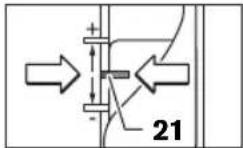
Jus Jus Jus Jus Jus Jus Jus Jus
P2 11 11 11 11 11 11 11
-
-
-
-
-
-
-
-
-
-
-
-
-
-
-
-
-
-
-
-
-
- 1.
-
-
-
-
-
-
-
-
-
-
-
-
-
-
-
-
-
-
-
-
J 1
aill baiil alo y
plo 27 aal al
44 45
j 180°
46 UyI 27 ayI yI yI yI
6 6
28 27
12
204|
yjnnn jy
*jj11 j0o p000000000 42
yj1i j 49
43
50
SDS 44
gall do jae aagwgl gaaal galsolal yjll 1
1
(2x) 45
46
47
L
| GOF 1300 CE Professional | GOF 900 CE Professional | الإستعمال |
| 0 601 614 6..0 601 613 6.. | الإستعمال | |
| 9001 300 | الإستعمال | |
| 12 000-24 00012 000-24 000 | الإستعمال | |
| ● | ● | الإستعمال |
| ● | ● | الإستعمال |
| ● | ● | الإستعمال |
| 6-12,7 | 6-8 | \( ^{ \text{❸}} \) |
| \( \frac{1}{4}-\frac{1}{2} \) | \( \frac{1}{4} \) | \( ^{ \text{❹}} \) |
| 58 | 50 | \( ^{ \text{❺}} \) |
| 3,54,8 | EPTA-Procedure 01/2003\( ^{ \text{❺}} \) | |
| \( \square \) | \( \square \) | \( ^{ \text{❺}} \) |
Aa 1230 [U]
aill 1y
CC
aaii iie
EN60745:
.2006/42/EG.2004/108/EG.2011/65/EU
:2006/42/EG)
Robert Bosch GmbH, PT/ETM9,
D-70745 Leinfelden-Echterdingen
Dr. Egbert Schneider
Senior Vice President
Engineering
Dr. Eckerhard Strötgen
Engineering Director
PT/ESI


Robert Bosch GmbH, Power Tools Division
D-70745 Leinfelden-Echterdingen
26.10.2011

(Aa)j
e 1
.
jill jil llll 1
1jJg
EN60745
yall bna sio (A g) j
(A__ij)_j = 1,2, ,n 100 all s.89
bn + 1 = bn + 2b_n
1
Kgll (Lalaiy Lg)ah jj
:EN60745
- 12 2,5 = K, 12 5,5 = a_h
yolw oia ccll ysiil jzjz1s jzpi
EN60745
J 1
a 1
jieell jae 100
jaii iis jia jai g. jil jaiy jai y jai 1
S AOB = S COD + S BOC - S COD
1
Jauy 10000000000000000000000000000000
Jol 1
Jouell
:100 1
Jaae aee
a. g 为正
a a 1
a
(jg jaoaai (204
2
3
4
gai gai jia jia jia jia jia jia jia jia jia jia jia jia jia jia jia jia jia jia jia jia jia jia jia jia jia jia jia jia jia jia jia jia jia jia
aaii jiey
J 1
e 1
a=paallae
()a
y j 1
Juaauii jaiyjaiy jiaiaiaia
Jaaadl Jaiy
a111111111111111111111111
ySjLl 100g y
jll jld lgl
gag gag gag gag gag gag gag gag gag gag gag gag gag gag gag gag gag gag gag gag gag gag gag gag gag gag gag gag gag gag gag gag gag gag
.
yIg 11
a 1
1 1 1 1 1 1 1 1 1 1 1 1 1 1 1 1 1 1 1 1 1 1 1 1 1 1 1 1 1 1 1 1 1 1 1 1 1 1 1 1 1 1 1
y 1111111111111111111111111111111111111111111
Jl 1 Jn Jn Jn Jn Jn Jn Jn Jn Jn Jn Jn Jn Jn Jn Jn Jn Jn Jn Jn Jn Jn Jn Jn Jn Jn Jn Jn Jn Jn Jn Jn Jn Jn Jn Jn Jn Jn Jn Jn Jn Jn Jn Jn Jn Jn Jn Jn Jn Jn Jn J
j 1 j 1 j 1 j 1 j 1 j 1 j 1 j 1 j 1 j 1 j 1 j 1 j 1 j 1 j 1 j 1 j 1 j 1 j 1 j 1 j 1 j 1 j 1 j 1 j 1 j 1 j 1 j 1 j 1 j 1 j 1 j 1 j 1 j 1 j
a 1 1 1 1 1 1 1 1 1 1 1 1 1 1 1 1 1 1 1 1 1 1 1 1 1 1 1 1 1 1 1 1 1 1 1 1 1
a a a a a a a a a a a a a a a a a a a a a a a a a a a a a
1
aIySlllal llo 1
1
J 111111111111111111111111111111111
1
J 150. g jg jg J 150. g jg jg J 150. g jg jg J 150. g jg jg J 150. g jg jg J 150. g jg jg J 150. g jg jg J 150. g jg jg J 150. g jg jg J 150. g jg jg J
S OBC = S ABC + S_ ABO
y. 11111111111111111111111111111111
a 1
1
a 1 a 1 1 1 1 1 1 1 1 1 1 1 1 1 1 1 1 1 1 1 1 1 1 1 1 1 1 1 1 1 1 1 1 1
Laiie Lai jy Jlaiu u 111111111111111111111111111111
y 1
y
1 1 1 1 1 1 1 1 1 1 1 1 1 1 1 1 1 1 1 1 1 1 1
J 1 J 1 J 1 J 1 J 1 J 1 J 1 J 1 J 1 J 1 J 1 J 1 J 1 J 1 J 1 J 1 J 1 J 1 J 1 J 1 J 1 J 1 J 1 J 1 J 1 J 1 J 1 J 1 J 1 J 1 J 1 J 1 J 1 J 1 J
oLao Lao,olaleo g s yjy jlew Lg Jgaiag S
jLgLgJgJLo
Inno hio 10000000000000000000000000000000000000000000000000
aLg 100
JL 47 s1s L g g 46 p01
g s1s L g 44 s1s L
15 15
a 100000000000000000000000000000000000000000000000
Lj 22012 12 12
148 49 sogac -
90a15 aao 50s5oL
45ggb4a
.5
475s 505s0s
48 48
50s0
22 1j
47 15
- 220015
122 1
JL 1000000000000000000000000000000000000000
a 1
01
JLai aLing. gjis1 j! gj y gj L a 5gj 1 j
jL 10
aR (RCD) 100000000000000000000000000000000000000000000000000000000000000000000000000
a 1 a 1 1 1 1 1 1 1 1 1 1 1 1 1 1 1 1 1 1 1 1 1 1 1 1 1 1 1 1 1 1 1 1 1 1 1 1 1
208 L
4g(g)g1goglaoljLdAeog (G
30 Laiol y 29 gol glalol 12
5gol 5 ailg jg 12
5gol 32 g 31 gglg
31 33 32 32
33 32 32
32 32 32
32 32 32
32 32 32
32 32 32
32 32 32
32 32 32
32 32 32
32 32 32
32 32 32
32 32 32
32 32 32
32
g 29 gjgo slqol, h s L glsjg pLio
27 35 gogao oio gog aai j gia
(Hyjgai yogg) jzjLgJy JyJzj
36 Laiol, Jy JyJyJyJyJyJyJyJyJyJyJyJyJyJyJyJyJyJyJyJyJyJyJyJyJyJyJyJyJyJyJyJyJyJyJyJyJyJyJyJyJyJyJyJyJyJyJyJyJyJyJy
Jg39 sI ailg y bI y Iy dI g y 40 JgS aas L
aiai i S y bI y Iy dI g y S y iaia i y
JgS aas S y bI y Iy dI g y S y iaia Iy
2,0 oJdI
0,1 oJdI ay aaiy
37jLg1wS 1 wuW S ayE W L uW g yB Jy
(Fgagaiyogg)Gc0s0gLgLgLg
p 1000000000000000000000000000000000000000000000000000000000000000000000000000000000
#
003yJ L(g-)j=120L00s000000000000000000000000000000000000
i j 5j10 as 5ggo L ijJao yao zio sIb i
Sis
a1 = 2,a2 = - 4
a.solaiu
glesggsjLaoas
123
0oaiip1P2jilao jio jiaojuyaoi ylojogao
g algoj 10LaIw L aBol j 3o g 2000
= ( = 1)
g 2.5.2. g] Jao: yjoo j0 2.9.2. 15 Jao 0, 0, 0, 0, 0, 0, 0, 0, 0, 0, 0, 0, 0
iJiei jilw aijjg o
joo01
27.
Jus 44 Jus
27.0180 180°jfo
j1 j4 2y j1 eL W pL a s i wL 46pL L
28 241,27 6
12
jLg gJooe:ws Jluog
26 (0 35 mm) s o i s o s
Jag(Laleo)gjg260a50gajg
.
g.1Lj 100
j0o olj juiis L ciuiu a jgao as jugcuw giaoo
100
g
1 1
g i 1jLbW g jioJxw yds Jy
yogosoo oolsoo 1jdy slo
A
jieh cww jgco aifw 1. jbi jogm
aLs gGg 1JgJg JgJg
1gjgljg 100
jg jy jbi jie o 0s L a s g
gLgwsjwgs;ps.10Lo gJgJgJgJgJgJgJgJg
sLS JLoJoo

a + b = 12
Jgaa 45, gjy jgbl gJxil jgmo Jgfoa
SjLgLojg,LoJalilwLg《giCulssogplo
gLgLoJgssuLgLbEN60745:
.2006/42/EG,2004/108/EG,2011/65/EU
:12006/42/EG)
Robert Bosch GmbH, PT/ETM9,
D-70745 Leinfelden-Echterdingen
Dr. Egbert Schneider
Senior Vice President
Engineering
Dr. Eckerhard Strötgen
Engineering Director
PT/ESI
ppa.
Robert Bosch GmbH, Power Tools Division
D-70745 Leinfelden-Echterdingen
26.10.2011

j# 2010, j# g a
(Agagadg
jLg1g1g1g2g2g1g1g1g2g2g1g
g iuus uus jus 1s jus J L Jolss g JlL aas oalw gJg JI Jauo algo aagus
jL jL pE g a 123456789011
aaiw jgao gaij 1g qaiy
slo jss swoo iio gaijg jolaiu. 1Lg Egi Li wliio gaijgaiolS. jaiqai
i 1000000000000000000000000000000000000000000000000000000000000000
1