USER MANUAL GSS 23 AE BOSCH
OB1DOKU-1211-005.fm Page 1 Thursday, March 10, 2016 9:27 AM
Robert Bosch Power Tools GmbH
70538 Stuttgart
GEMANY
www.bosch-pt.com
160992A2BP(2015.03)0/150EURO

160992A2BP
GSS 23 AE Professional
no Original mullinsstocks
Aikupera setohet
e
Original lctre talmae
pl Instrukcia oryinalna
cs Puvodni nayod k pouzivani
sk Povodny naevd na poufite
huFucuhsy
CHINHANHOE DKKDPOETEOE
AKCENWATAUH
uk OparHanha hctpyckul a
eKryatau
kk Naganaity mycayibranin
TYNCKACU
roInstruetiuni original
bgOpHannnHaHcTpyKpn
mkOpnnnnoynnnae 3pa

BOSCH
sr Original uputstvo zara
slizvima nayodia
hr Originale upute zaraad
et Alugiraar kasa huihao
h
Onsali jostukzka
2
4
1a

2
Deutsch. 6
English
Francais .Page 15
Espanol. Pagina 20
Portugues . Pagina 25
Italiano 30
Nederlands.. 35
Dansk . 39
Svenska Sida 43
Norsk. Side 47
Suomi. Sivu 51
EAnvika 55
Türkce. Sayfa 60
Polski Strona 65
Cesky Strana 70
Slovensky Strana 74
Magyar Oldal 79
Pycckn CtpaHua 84
YkpaHcbKa. CToPiHa 90
Kazakwa .Ber 95
Romána. . 100
BbIrapckn .. CtrpaHnca 104
MaKeDoHcKn CtpaHa 109
Srprski Strana 114
Slovensko Stran 118
Henk Becker
Executive Vice President
Engineering
Helmut Heinzelmann
Head of Product Certification
PT/ETM9

Robert Bosch Power Tools GmbH
70538 Stuttgart,GERMANY
Stuttgart, 01.01.2017
Montage
WARNING
Read all safety warnings and all instructions. Failure to follow the warnings
and instructions may result in electric shock, fire and/or serious injury.
Save all warnings and instructions for future reference.
The term "power tool" in the warnings refers to your mains-operated (corded) power tool or battery-operated (cordless) power tool.
Work area safety
- Keep work area clean and well lit. Cluttered or dark areas invite accidents.
Do not operate power tools in explosive atmospheres, such as in the presence of flammable liquids, gases or dust. Power tools create sparks which may ignite the dust or fumes.
- Keep children and bystanders away while operating a power tool. Distractions can cause you to lose control.
Electrical safety
Power tool plugs must match the outlet. Never modify the plug in any way. Do not use any adapter plugs with earthed (grounded) power tools. Unmodified plugs and matching outlets will reduce risk of electric shock.
- Avoid body contact with earthed or grounded surfaces, such as pipes, radiators, ranges and refrigerators. There is an increased risk of electric shock if your body is earthed or grounded.
Do not expose power tools to rain or wet conditions. Water entering a power tool will increase the risk of electric shock.
Do not abuse the cord. Never use the cord for carrying, pulling or unplugging the power tool. Keep cord away from heat, oil, sharp edges and moving parts. Damaged or entangled cords increase the risk of electric shock.
When operating a power tool outdoors, use an extension cord suitable for outdoor use. Use of a cord suitable for outdoor use reduces the risk of electric shock.
If operating a power tool in a damp location is unavoidable, use a residual current device (RCD) protected supply. Use of an RCD reduces the risk of electric shock.
Personal safety
Stay alert, watch what you are doing and use common sense when operating a power tool. Do not use a power tool while you are tired or under the influence of drugs, alcohol or medication. A moment of inattention while operating power tools may result in serious personal injury.
Use personal protective equipment. Always wear eye protection. Protective equipment such as dust mask, non-skid safety shoes, hard hat, or hearing protection used for appropriate conditions will reduce personal injuries.
Prevent unintentional starting. Ensure the switch is in the off-position before connecting to power source and/or battery pack, picking up or carrying the tool. Carrying power tools with your finger on the switch or energising power tools that have the switch on invites accidents.
Remove any adjusting key or wrench before turning the power tool on. A wrench or a key left attached to a rotating part of the power tool may result in personal injury.
Do not overreach. Keep proper footing and balance at all times. This enables better control of the power tool in unexpected situations.
Dress properly. Do not wear loose clothing or jewellery. Keep your hair, clothing and gloves away from moving parts. Loose clothes, jewellery or long hair can be caught in moving parts.
If devi s are provided for the connection of dust extraction and collection facilities, ensure these are connected and properly used. Use of dust collection can reduce dust-related hazards.
Do not force the power tool. Use the correct power tool for your application. The correct power tool will do the job better and safer at the rate for which it was designed.
Do not use the power tool if the switch does not turn it on and off. Any power tool that cannot be controlled with the switch is dangerous and must be repaired.
- Disconnect the plug from the power source and/or the battery pack from the power tool before making any adjustments, changing accessories, or storing power tools. Such preventive safety measures reduce the risk of starting the power tool accidentally.
- Store idle power tools out of the reach of children and do not allow persons unfamiliar with the power tool or these instructions to operate the power tool. Power tools are dangerous in the hands of untrained users.
- Maintain power tools. Check for misalignment or binding of moving parts, breakage of parts and any other condition that may affect the power tool's operation. If damaged, have the power tool repaired before use. Many accidents are caused by poorly maintained power tools.
- Keep cutting tools sharp and clean. Properly maintained cutting tools with sharp cutting edges are less likely to bind and are easier to control.
- Use the power tool, accessories and tool bits etc. in accordance with these instructions, taking into account the working conditions and the work to be performed. Use of the power tool for operations different from those intended could result in a hazardous situation.
Service
Have your power tool serviced by a qualified repair person using only identical replacement parts. This will ensure that the safety of the power tool is maintained.
12 | English
SafetyWarnings for Sander
Use the machine only for dry sanding. Penetration of water into the machine increases the risk of an electric shock.
- Caution, fire hazard! Avoid overheating the object being sanded as well as the sander. Always empty the dust collector before taking breaks. In unfavourable conditions, e.g., when sparks emit from sanding metals, sanding debris in the dust bag, micro filter or paper sack (or in the filter sack or filter of the vacuum cleaner) can self-ignite. Particularly when mixed with remainders of varnish, polyurethane or other chemical materials and when the sanding debris is hot after long periods of working.
When working with the machine, always hold it firmly with both hands and provide for a secure stance. The power tool is guided more secure with both hands.
Secure the workpiece. A workpiece clamped with clamping devices or in a vice is held more secure than by hand.
Products sold in GB only: Your product is fitted with a BS 1363/A approved electric plug with internal fuse (ASTA approved to BS 1362).
If the plug is not suitable for your socket outlets, it should be cut off and an appropriate plug fitted in its place by an authorised customer service agent. The replacement plug should have the same fuse rating as the original plug.
The severed plug must be disposed of to avoid a possible shock hazard and should never be inserted into a mains socket elsewhere.
Products sold in AUS and NZ only: Use a residual current device (RCD) with a rated residual current of 30mA or less.
Product Description and Specifications

Read all safety warnings and all instructions. Failure to follow the warnings and instructions may result in electric shock, fire and/or serious injury.
While reading the operating instructions, unfold the graphics page for the machine and leave it open.
Intended Use
The machine is intended for dry sanding of wood, plastic, filler and coated surfaces.
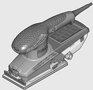
Product Features
The numbering of the product features refers to the illustration of the machine on the graphics page.
1 Thumbwheel for orbit frequency preselection
2 On/Off switch
3 Lock-on button for On/Off switch
4 Dust box, complete (Microfilter System)
5 Sanding-sheet clamp
6 Sanding plate
7 Sanding sheet
8 Release button for front clamping bracket
9 Front clamping bracket
10 Perforating tool
11 Screws for sanding plate
12 Extraction outlet
13 Filter element (Microfilter System)
14 Vacuum hose
15 Handle (insulated gripping surface)
*Accessories shown or described are not part of the standard delivery scope of the product. A complete overview of accessories can be found in our accessories program.
Technical Data
| Orbital sander GSS 23 AE |
| Article number | | 3601 K70 7.. |
| Rated power input | W | 190 |
| Preselection of orbital stroke rate ● | | |
| No-load speed | min-1 | 7000 - 1200 |
| No-load orbital stroke rate | min-1 | 14000 - 24000 |
| Orbit diameter | mm 2.0 |
| Sanding sheet dimensions | | |
| -Adhesion via Velcro backing | mm | 93 x 185 |
| -Attachment via clamping | mm | 93 x 230 |
| Sanding plate dimensions | mm 92 x 182 |
| Weight according to EPTA-Procedure 01:2014 | kg 1.7 |
| Protection class | | ☐/II |
| The values given are valid for a nominal voltage [U] of 230 V. For differ-ent voltages and models for specific countries, these values can vary. |
Sound emission values determined according to EN 60745-2-4.
Typically the A-weighted noise levels of the product are: Sound pressure level 80 dB(A);Sound power level 91 dB(A). Uncertainty K = 3 dB.
Wear hearing protection!
Vibration total values a_h (triax vector sum) and uncertainty K determined according to EN 60745-2-4: a_h = 4.5m / s^2,K = 1.5m / s^2
The vibration level given in this information sheet has been measured in accordance with a standardised test given in EN 60745 and may be used to compare one tool with another. It may be used for a preliminary assessment of exposure. The declared vibration emission level represents the main applications of the tool. However if the tool is used for different applications, with different accessories or insertion tools or is poorly maintained, the vibration emission may differ. This may significantly increase the exposure level over the total working period.
An estimation of the level of exposure to vibration should also take into account the times when the tool is switched off or when it is running but not actually doing the job. This may significantly reduce the exposure level over the total working period.

English|13
Identify additional safety measures to protect the operator from the effects of vibration such as: maintain the tool and the accessories, keep the hands warm, organisation of work patterns.

We declare under our sole responsibility that the product described under "Technical Data" is in conformity with all relevant provisions of the directives 2011/65/EU, until 19 April 2016: 2004/108/EC, from 20 April 2016 on: 2014/30/EU, 2006/42/EC including their amendments and complies with the following standards: EN 60745-1, EN 60745-2-4, EN 50581.
Technical file (2006/42/EC) at: Robert Bosch Power Tools GmbH, PT/ETM9, 70538 Stuttgart, GERMANY
Henk Becker
Executive Vice President Engineering
Helmut Heinzelmann
Head of Product Certification
PT/ETM9

Robert Bosch Power Tools GmbH
70538 Stuttgart,GERMANY
Stuttgart, 01.01.2017
Assembly
Before any work on the machine itself, pull the mains plug.
Dusts from materials such as lead-containing coatings, some wood types, minerals and metal can be harmful to one's health. Touching or breathing in the dusts can cause allergic reactions and/or lead to respiratory infections of the user or bystanders.
Certain dusts, such as oak or beech dust, are considered as carcinogenic, especially in connection with wood-treatment additives (chromate, wood preservative). Materials containing asbestos may only be worked by specialists.
- As far as possible, use a dust extraction system suitable for the material.
- Provide for good ventilation of the working place.
- It is recommended to wear a P2 filter-class respirator.
Observe the relevant regulations in your country for the materials to be worked.
Prevent dust accumulation at the workplace. Dusts can easily ignite.
Attach the dust box 4 onto the extraction outlet 12 until it latches.
To empty the dust box 4, pull off the dust box downward.
Before opening the dust box 4, it is recommended to loosen the dust from the filter element by gently striking it against a firm support (as shown in the figure).
Grasp the dust box 4 by the recessed grip, fold the filter element 13 upward and empty the dust box. Clean the thin plates of the filter element 13 with a soft brush.
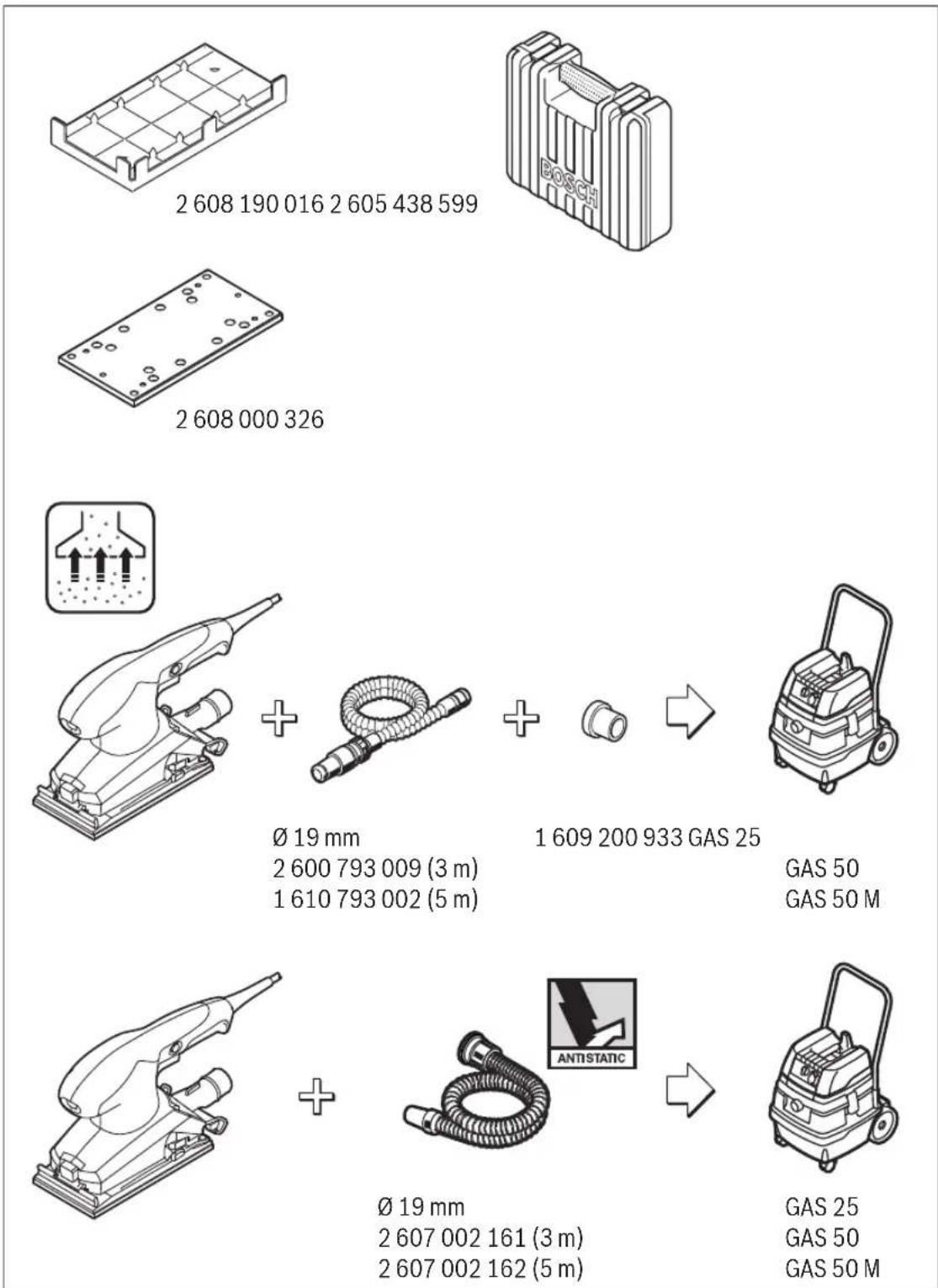
Mount a vacuum hose 14 onto the extraction outlet 12. Connect the vacuum hose 14 with a vacuum cleaner. An overview for the connection of various vacuum cleaners can be found at the end of these instructions.
The vacuum cleaner must be suitable for the material being worked.
When vacuuming dry dust that is especially detrimental to health or carcinogenic, use a special vacuum cleaner.
Replacing the Sanding Sheet
When attaching a new sanding sheet, remove any dust or debris from the sanding plate 6 (e.g. with a brush).
To ensure optimum dust extraction, pay attention that the punched holes in the sanding sheet match with the holes in the sanding plate.
The sanding plate 6 is fitted with Velcro backing for quick and easy fastening of sanding sheets with Velcro adhesion.
Before attaching the sanding sheet 7, free the Velcro backing of the sanding plate 6 from any debris by tapping against it in order to enable optimum adhesion.
Position the sanding sheet 7 flush alongside one edge of the sanding plate 6, then lay the sanding sheet onto the sanding plate and press firmly.
To remove the sanding sheet 7, grasp it at one of the tips and pull it off from the sanding plate 6.
Press the release button 8 and keep it depressed.
Guide the sanding sheet 7 to the stop under the opened front clamping bracket 9 and let go of the release button 8 again. Pay attention that the sanding sheet is clamped centrally.
Press the sanding sheet clamp 5 inward and pivot it to the stop.
Fold the sanding sheet 7 firmly around the sanding plate. Guide the other end of the sanding sheet 7 between the rear clamping bracket and the red roller on the clamping bracket 5.
Hold the sanding sheet densely and press the clamping bracket 5 toward the sanding plate to lock the sanding sheet.
Sanding sheets without holes, e. g. from rolls or by the meter, can be punctured with the perforating tool 10 for use with dust extraction. For this, press the machine with the mounted sanding sheet onto the perforating tool (see figure E).
To remove the sanding sheet 7, loosen the clamping bracket 5 and pull out the sanding sheet from the rear holding fixture. Press the release button 8 and completely remove the sanding sheet.


14|English
Selecting the Sanding Sheet
Depending on the material to be worked and the required rate of material removal, different sanding sheets are available:
Grain size
40-240
red:Wood
For the working of all wooden materials
For coarse-sanding, e. g. of rough, unplaned beams and boards coarse 40, 60
For face sanding and planing small irregularities medium 80,100,120
For finish and fine sanding of hard woods fine 180,240
white:Paint
40-320
For the working of paint/enamel coats or primers and fillers
For sanding off paint coarse 40, 60
For sanding primer medium 80, 100, 120
For final sanding of primers before coating fine 180,240,320
The sanding plate 6 can be replaced, if required.
Unscrew the 4 screws 11 completely and remove the sanding plate 6. Attach the new sanding plate 6 and tighten the screws again.
Operation
Starting Operation
Observe correct mains voltage! The voltage of the power source must agree with the voltage specified on the nameplate of the machine. Power tools marked with 230V can also be operated with 220V .
Switching On and Off
To start the machine, press the On/Off switch 2 and keep it pressed.
To lock the pressed On/Off switch 2, press the lock-on button 3.
To switch off the machine, release the On/Off switch 2 or when it is locked with the lock-on button 3, briefly press the On/Off switch 2 and then release it.
To save energy, only switch the power tool on when using it.
Preselecting the Orbital Stroke Rate
With the thumbwheel for preselection of the orbital stroke rate 1, you can preselect the required orbital stroke rate, even during operation.
The required stroke rate depends on the material and the working conditions and can be determined through practical testing.
Working Advice
Wait until the machine has come to a standstill before placing it down.
Before any work on the machine itself, pull the mains plug.
The removal capacity during sanding is mainly determined by the selection of the sanding sheet as well as the preselected orbital stroke rate.
Only flawless sanding sheets achieve good sanding capacity and extend the service life of the machine.
Pay attention to apply uniform sanding pressure; this increases the working life of the sanding sheets.
Intensifying the sanding pressure does not lead to an increase of the sanding capacity, but to increased wear of the machine and the sanding sheet.
A sanding sheet that has been used for metal should not be used for other materials.
Use only original Bosch sanding accessories.
Maintenance and Service
Maintenance and Cleaning
Before any work on the machine itself, pull the mains plug.
For safe and proper working, always keep the machine and ventilation slots clean.
If the replacement of the supply cord is necessary, this has to be done by Bosch or an authorized Bosch service agent in order to avoid a safety hazard.
After-sales Service and Application Service
In all correspondence and spare parts order, please always include the 10-digit article number given on the type plate of the machine.
Our after-sales service responds to your questions concerning maintenance and repair of your product as well as spare parts. Exploded views and information on spare parts can also be found under:
www.bosch-pt.com
Bosch's application service team will gladly answer questions concerning our products and their accessories.
Great Britain
Robert Bosch Ltd. (B.S.C.)
P.O.Box 98
Broadwater Park
North Orbital Road
Denham
Uxbridge
UB95HJ
At www.bosch-pt.co.uk you can order spare parts or arrange the collection of a product in need of servicing or repair.
Tel. Service: (0344) 7360109
E-Mail: boschservicecentre@bosch.com


Francais|15
Ireland
Origo Ltd.
Unit 23 Magna Drive
Magna Business Park
City West
Dublin 24
Tel. Service: (01) 4666700
Fax: (01) 4666888
Australia, New Zealand and Pacific Islands
Robert Bosch Australia Pty. Ltd.
Power Tools
Locked Bag 66
Clayton South VIC 3169
Customer Contact Center
Inside Australia:
Phone: (01300) 307044
Fax: (01300) 307045
Inside New Zealand:
Phone: (0800) 543353
Fax: (0800) 428570
Outside AU and NZ:
Phone: +61 395415555
www.bosch.com.au
Republic of South Africa
Customer service
Hotline: (011) 6519600
Gauteng - BSC Service Centre
35 Roper Street, New Centre
Johannesburg
Tel.: (011) 4939375
Fax: (011) 4930126
E-Mail: bsctools@icon.co.za
KZN - BSC Service Centre
Unit E, Almar Centre
143 Crompton Street
Pinetown
Tel.: (031) 7012120
Fax: (031) 7012446
E-Mail: bsc.dur@za.bosch.com
Western Cape - BSC Service Centre
Democracy Way, Prosperity Park
Milnerton
Tel.: (021) 5512577
Fax: (021) 5513223
E-Mail: bsc@zsd.co.za
Bosch Headquarters
Midrand, Gauteng
Tel.: (011) 6519600
Fax: (011) 6519880
E-Mail: rbsa-hq.pts@za.bosch.com
Disposal
The machine, accessories and packaging should be sorted for environmental-friendly recycling.
Only for EC countries:
According to the European Directive 2012/19/EU for Waste Electrical and Electronic Equipment and its implementation into national right, power tools that are no longer usable must be collected separately and disposed of in an environmentally correct manner.
Subject to change without notice.
Français
$$
a _ {n} = 4, 5 m / s ^ {2}, K = 1, 5 m / s ^ {2}.
$$
Executive Vice President
Engineering
Helmut Heinzelmann
Head of Product Certification
PT/ETM9

Robert Bosch Power Tools GmbH
70538 Stuttgart,GERMANY
Stuttgart, 01.01.2017
Montage
Robert Bosch (France) S.A.S.
Executive Vice President
Engineering
Helmut Heinzelmann
Head of Product Certification
PT/ETM9

Robert Bosch Power Tools GmbH
70538 Stuttgart,GERMANY
Stuttgart, 01.01.2017
Montaje
Executive Vice President Engineering
Helmut Heinzelmann
Head of Product Certification
PT/ETM9

Robert Bosch Power Tools GmbH
70538 Stuttgart,GERMANY
Stuttgart, 01.01.2017
Montagem
- Antes de todoseworkos na ferramenta eletrica develerá puxar a ficha de rede da tomada.
Executive Vice President
Engineering
Helmut Heinzelmann
Head of Product Certification
PT/ETM9

Robert Bosch Power Tools GmbH
70538 Stuttgart,GERMANY
Stuttgart, 01.01.2017
Montaggio
Executive Vice President
Engineering
Helmut Heinzelmann
Head of Product Certification
PT/ETM9

Robert Bosch Power Tools GmbH
70538 Stuttgart,GERMANY
Stuttgart, 01.01.2017
Montage
Executive Vice President
Engineering
Helmut Heinzelmann
Head of Product Certification
PT/ETM9

Robert Bosch Power Tools GmbH
70538 Stuttgart,GERMANY
Stuttgart, 01.01.2017
Montering
Bosch Service Center
Telegrafvej 3
2750 Ballerup
Pá www.bosch-pt.dk kander online bestilles reservedeleller oprettes en reparations ordre.
Tlf. Service Center: 44898855
Fax: 44898755
E-Mail: vaerktoej@dk.bosch.com
Bortskaffelse
Executive Vice President Engineering
Helmut Heinzelmann
Head of Product Certification PT/ETM9

Robert Bosch Power Tools GmbH
70538 Stuttgart,GERMANY
Stuttgart, 01.01.2017
Montage
Dra stickproppen ur nätuttaget innan arbeten utfors pa elverktyget.
Damm-/spanutsugning
Bosch Service Center
Telegrafvej 3
2750 Ballerup
Danmark
Tel.: (08) 7501820 (inom Sverige)
Fax: (011) 187691
Avfallshantering
Executive Vice President Engineering
Helmut Heinzelmann
Head of Product Certification PT/ETM9

Robert Bosch Power Tools GmbH
70538 Stuttgart,GERMANY
Stuttgart, 01.01.2017
Montering
Executive Vice President
Engineering
Helmut Heinzelmann
Head of Product Certification
PT/ETM9

Robert Bosch Power Tools GmbH
70538 Stuttgart,GERMANY
Stuttgart, 01.01.2017
Asennus
Executive Vice President Engineering
Helmut Heinzelmann
Head of Product Certification
PT/ETM9

Robert Bosch Power Tools GmbH
70538 Stuttgart,GERMANY
Stuttgart, 01.01.2017
SuvapuOaoynon
Tw npv to 0 Aen180,240,320
Avtikataoataon nnc nakac leiavoc (Bene eikova F)
Suvtnpnon kal Service
Euvtnpnon kalkaogapiooC
ByaCte to qic ano nV npia npv ano onouabnore epyaia oto nAektpko epyaleio.
IatnpieTe to nAektpko epyaaleo kai tC oxtoepc aepi- kaOapeyva mopeite va epyaeeKa Ka aopaaoc.
Mia tuxov avaykaia avtikataaon Tou nAektpkou Kaawdiou npenei va dieqaxtheta ano tvn Bosch h ano eva eouaofo nevo katotma Service Tnc Bosch, yia va anopexutheta etai kaedeltaakivduveuaTNC aopaaleiac.
60 | Türkçe
Service ka npoxn oumuov xpionc
'Orav zntate diaaaopntikc nnpoopoeic kaohc kalotavnapayyelaveaatakkapenei va aapepeote onwohnoto 10qpiio apioeupetniou ouaypapetalnivakida kataokueaon.
To Service anavta otic epwthaeic oac oxetikae tyn enokuei kai tn ouvtnpon tou npoiovoc ac kaohc yia ta katalnaa avtaaktkia:
H ouda npaoxnc oupouw tvc Bosch anavta euxapiotoc icepwnoeic oac oxetik a ta npoiovta mac kal a vtaaaktikouc.
EAAaδa
Robert Bosch A.E.
Eoxy1ac 37
19400Kopwni-Athya
Tnλ.: 2105701258
Φaξ:2105701283
www.bosch.com
www.bosch-pt.gr
ABZ Service A.E.
Tnλ: 2105701380
Φaξ: 2105701607
Anoupon
Ta nAektpkApyaia, ta eapntmuata kai ooukeuaoeic npenei va avakukawovtai pe npno pfikko npoc to nepiBaalov.
Movi yia xowpec tnc EE:
Σμφωνa με Νην Koivotικ Μόγια
2012/19/EE oxetiká με τι παλaiες ήεκτριkec kalæntóvoviké σοκeueç kalημετapopá tnc odnyiaac autnca eθviko δikaio devéiva nleov unoxpewtko ta axonotra λεκτρika εpyaleia va ouλeoyovat fexomegaia yia va avakukawθouv με Πpno φιλiok npoc to nepiβaλov.
Tnpoue to dikaiwma aalayov.
Türkce
Güvenlik Talimati
Elektrikli El Aletleri Icin Genel Uyar Talimati
Executive Vice President
Engineering
Helmut Heinzelmann
Head of Product Certification
PT/ETM9

Robert Bosch Power Tools GmbH
70538 Stuttgart,GERMANY
Stuttgart, 01.01.2017
Montaj
Bosch San. ve Tic. A.S.
Ahi Evran Cad. No:1 Kat:22
Polaris Plaza
80670 Maslak/Istanbul
Bosch Uzman Ekibi +90 (0212) 367 18 88
Isiklar LTD. STI.
Kizilay Cad. No: 16/C Seyhan
Adana
Tel.: 0322 3599710
Tel.: 0322 3591379
Henk Becker
Executive Vice President
Engineering
Helmut Heinzelmann
Head of Product Certification
PT/ETM9

Robert Bosch Power Tools GmbH
70538 Stuttgart, GERMANY
Stuttgart, 01.01.2017
Montaz
Robert Bosch Sp. z o.o.
Executive Vice President Engineering
Helmut Heinzelmann
Head of Product Certification PT/ETM9

Robert Bosch Power Tools GmbH
70538 Stuttgart,GERMANY
Stuttgart, 01.01.2017
Montáz
Pred kazdou pracina elektronaradiyvtahnete zastrcku zezasuvky.
Odsavani prachu/trisek
Bosch Service Center PT
K Vapence 1621/16
692 01 Mikulov
Na www.bosch-pt.cz si si muzete objednat opravu Vaseho stroje nebo nahradni dily online.
Tel.: 519305700
Fax: 519305705
E-Mail: servis.naradi@cz.bosch.com
www.bosch.cz
Zpracováni odpadú
Executive Vice President
Engineering
Helmut Heinzelmann
Head of Product Certification
PT/ETM9

Robert Bosch Power Tools GmbH
70538 Stuttgart,GERMANY
Stuttgart, 01.01.2017
Montáž
Executive Vice President Engineering
Helmut Heinzelmann
Head of Product Certification
PT/ETM9

Robert Bosch Power Tools GmbH
70538 Stuttgart,GERMANY
Stuttgart, 01.01.2017
Összeszerelés
PekomeHcyTeCAOHTb HCTpyMeHOT nbIINIOcNEKaXdo-TOHCNONb3OBaHH.
Xpahnne
- Heo6xOIMO xpaHnTB bCyXOM MecTe
Heo6xOIMO XpaHnTB BdaIIN OT hCOTUHNKOB NOBbIeHHbx Tempeatyp IN BO3dEChTBn COJIHeuHbIX nyuei
- npxpaHenn Heo6xOdmo H36erTb pe3Koro nepenada Tempepatyp
-xpaHHe 6e3 ynaKOBKn He DonyckaTcA
- noipobnbte Tpe6oBaHnK yCNoBnM xpaHeHn CMOtpnte B FOCT 15150 (YcNoBne 1)
TpaHcnpTnpoBka
- kateropueckn He donyckaetra naeHne nIObIe mexa Hnueckn BO3dEiCTBna Ha yNAKOBY npuTpaHCnpTPOBKe
- npn pa3rpy3ke/norpy3ke He donnyckaetc nncnoIb3oBaHne IIO60rO BuaTeXHHK,pa6ToaUeHnnpnHnny 3aKmMa ynaKOBKn
-NOpObHbIe Tpe6oBaHHaK YcNoBnAM TpaHCnOpTnpOBKn CMOTPHTBFOCT15150(YcNoBne5)
Yka3aHnno6e3oNaCHOCTN
06uhe yka3aHnnoTexnke 6e3onacHOCTn dna 3NeKtpoHHcTpymeHTOB
A PNEDAYNPPEXKDEHME
IpoHTHe Bce yKa3aHnH N HcTpyKuHn No TeXnKe
6e3onachocTH. HecobnOedHne yka3aHH n HNCTpyKuHn no TexHke 6e3oNaChocTH MoKeT CTaTB pNpHNOI npaKeHHa 3JIeKTpuCeckHM TOKOM, NOkapa N TaXeJbIX TpaBM.
CoxpaHnTe 3TH HnCTpyKuHH uKa3aHHn dnn 6yduero nCnoB3OBAHH.
NcnoB30BaHHoe B HactoHx HnHctpyKuHX yKa3aHnx noHrTne 3eKtpOnHCTpyMeHT pacpOcTaPHeTcRa Ha 3eKtpOnHCTpyMeHT C nIITAHmEOT cETn (C cTeBbIM WHypOM) HA aKKyMyJATOpHbI 3eKtpOnHCTpyMeHT (6e3 cTeBOrO WHypa).
Be3onachoctb pa6oeryMecta
Copeknte pa6ooyee MeTo B uHcTote H xopoOo OceEeHHbIM. 5ecnpaOK HnH HeOcBSeHHbIe yAcTKn pa6oeryo MeTaMOrT pINbEChK HecuACThBm CnyaAM.
He pa6oTaIe c 3THM 3NEKtpOHCTpyMeHOTMO B3pblBOONaCHOM NOMEUeHHN, B KOTOPOM HAXOHTC TROP0YHE XIKOCtH, BOCnPaMeHaIOUeCe rA3bI HIN PbIb.3NEKtpOHCTpyMeHtB HCKPRT, YTO MOKeT PIPBEcTH K BOCnPaMeHeHIO PbIIN HIN NapOB.
BoBpMaPbOtBc3NeKTPoHnCTpyMeHTOM He DonyckaIe 6bn3ko K Bauemy paobemy MecyTe HnNoctopoHHx nU. OTBneKwncb, Bbl MoKeTe NoTePrtb KOHTPOlb HaD 3NeKTPoHnCTpyMeHTOM.
3eKtpo6e3oNaChocTh
WTeNCbHbBnKa3NeKtpOHcTpymeHaDOnxHa NOxOHTbK WTeNCbHbHO po3EKe. HN B KOem cnyae He N3MeHnIte WTeNCbHbHyIO BnKy. He npMehnIte NepexOHBle WTeKepblIg 3NeKtpOHcTpymeHToB C 3aunTHbIM 3a3EmHeHm. Hen3MeHnHbIe WTeNCbHbIe BnIKu INoXoJHue WTeNCbHbIe po3EKn CHN KaIOT PnCK IopAkeHn 3NeKTPOTOKOM.
IpeoTbpaaTe TenechBIOKoTAKTc3a3eMHeHHbIMN NOBepxHocTAMN, KAK TO: c Tpy6AMn, 3eMeENTAMN OTOIIeHHN, KXOHbIMN NITAMN XOJOnHbHKAMN. Pn3 3a3eMHeHH BaWero Tena nobbiaaetc npck nopaxehn 3NEKPTOTOKOM.
3aunauTe 3eKTPOHnHCTpyMeHOTdoxNn HcbipocTH. PPOHKNHOBEHNE BObI B 3eKTPoHNHCTpyMeHNT NOBbIaet PnCKnopaxEHn 3eKTPoTOKOM.
He pa3pewaetca HcNoIb3ObaTb WHyp He no Ha3HaueHHIO, HApHMeP, Dnra TpaHCnOpTHPOBKn HnN NOBBeCKN 3NeKTPoHNCTpyMeNTA, HnN DnA BbITRnBaHnB BUNKN H3 WTeNCbHoPi03EtKn. 3aunuatae WHyp OT BO3DeICTBnB BBICOKHX TeMnepaTyp, Macna, OcTpbiX KpOMOKnn NNOBnKhbix qactei 3eKTPoHNCTpyMeNTa. NobpeKJDeHHbI INN CNYTaHHbI WHyp NOBbIaet pNCK npaKeHHN 3JIeKTPOTOKOM.
Pycckn|85
Pn pa6ote c 3neKtpoHcTpyMeHTOM NOtOKpbItbIM He6om npHMehIe nproDhble Ia 3TOr Ka6enn-ydnnHntenn. PpMHEnHe nproDHOIra pa60tI NOtO KpbITbIM He6om Ka6en-YdHHNTe CHNkaet pck nopaKeHHa 3NEKPTOKOM.
EcnH HeBO3MOXHO 36ExKaTb npmHeHen H3NeKTPoHNCTpyMeHTA B cIpOM NOMEeHHN, NOKJIIOaHTe 3NeKTPoHNCTpyMeHT Ype3 yCTPOHCTBO 3aUNTHORO OTKIOueHHN. PnIMHeHENy yCTPOHCTBA 3aUNTHORO OTKIOueHHN CHINKaET pCK 3NEKTPuueCKTO NOPaKeHHN.
Be3oNaChocThIIODeI
BybTe BHNMaTeBHBIMn, CneHnte 3a Tem, YTo BbldeNaete, H npOpyMaHNO HaunHaIe paBoTy c 3NeKtpOnHCTpyMeHOM. He nolb3yItec 3NeKtpOnHCTpyMeHOM Byctanom CoCToHHN HnE cCnH Bbl haoDITecb COCToHHN HApKOthueCKTO Hn ANKOrONbHO To ONbAHHeHHN Hn Np Bo3JeHCTBHeM JeKapCTB. OdH NmOHENT HeBHMaTeBHoCTn PnPaBoTe C 3NeKtpOnHCTpyMeHOTOM MOKeT PnHBecTH K cepBe3HbIM TpaBMam.
PnHMeHHeTe CpeCTBa HnHbNHyaNbHo3aunTbH Bcerda 3aunTHbte OcKn. NcNoIb3ObaHne CpeCTB INHINBnYabHO3aunTbK, KaT To: 3aunTHoM MaCKn, Obyn HaHEckOnb3aJeI NOoUBe, 3aunTHOrO UJema HnH CpeCTB 3aunTbI opraHOB CnyxA, -B 3aBNCmOCTN OT BnDa pa60TbIC 3eKTPoHHCTpyMeHTo CMnKaet PnCK NpUyeHnTPaBM.
PpeoTbpaaTe HnpeHaMepeHHe BkIOueHne 3NEKTPOHCTpyMeHTA. Pepe NODKIOUeHEm 3NEKTPOHCTpyMeHTA K 3NEKTPONITAHNO H/NN K aKKyMnIaTOpy y6eHntecB BBkIOUeHHOM COCTOHHN 3NEKTPOHCTpyMeHTA.YepKaHHe NaJIbua Ha BBkIOuata TeJe npTrpAHCnOpTIPOBKe 3NEKTPOHCTpyMeHTA NODKIOUeHHe K cTeN IITaHnBkIOUeHHOrO 3NEKTPOHCTpyMeHTa YpeBaTO HeCCHACTbIMN CnyaAMN.
y6npaTe yctahOBouhH HnCTpyMeH nHraeHbIe KIOuH Do BkIOUeHHN 3NEKtpOHCTpyMeHa. IHCTpyMeHT NIKIOU, HAXOJUHNCB O BpaAIOUeHcYacTHN 3NEKTPOHCTpyMeHa, MOXET PnHBECTN KTPaBMam.
He npHHMaIte HeecTeBcHHOe NOJoxHeN KOpnyCa TeJa. Bcerda 3aHMaIte yToCHBOe NOJoxHeN coXpaHnIte paBHOBecHe. BnaIgApA 3tOMy BbIMoKTe LyuIe KOHTpONIpOBAb 3JIeKTPOHNCTpyMeH T BHeOxNuHaH HbIX CNTyaUHX.
Hocnte noxognyo pa6oyuO odexy. He hocnte npokyo odexny H ykpaewen. Depxnte BONocbl, odexdy npkyabnbldnnOT DBNxyuxxcraactei. 1npokay oedka, ykpaewen Hn nnHHbte BONcbl Mo- rtyt btaTAYHbI BpaaohumncaractmN.
PnHaHnHnBO3MOxHOCHTyCTAHOBKNbIeOTcabBaHOxNbIeNC6OpBHyXyCTpOHTBnpOBeprTeHX npHoCoEHNHeHneNpABNbHoeHCNoB3OBaHne.PnMeHHeNpBIeOTCocAMoKETCHNtBOnaCHOCT,CO3daBaemyIOPiIbIO.
PpHmHeHHe 3JIeKtpOnHcTpymEHTa H o6paueHne c HMM
He neperpykaite 3neKtpoHnCTpyment. McnoIb3yIte DnBaWe pa60tbi npedHa3NaueHHbI dna 3TOREneKtpoHnCTpyment.CnOxDxOJaIM 3neKtpoHnCTpyMeHTOM Bby pa60taete lyuwe n HadeXHee BykazAHHom DnApa3OHe MoUHOCTH.
He pa6oTaIe c3NeKTPoHnHCTpyMeHTOM npH HenCnPaB HOM BbIKIOuATEne.3NeKTPoHnHCTpyMeHT, KOtOpBn He IOndaetcBAKIIQUeHHIO NIN BBIKIOUeHHIO, ONaCeH nOJKeH 6bItb OTpeMOHTnpOBaH.
I O NaHaJn HanaKn 3neKtpOnHcTpymeHTa, nepe 3aMeHOI pInHaJnEcxHocTe H npeKpaUeHHm pa60tIOTKNIOuAte WtTencBHyU BnNKy OTpO3TKn CeTHN/NNBbHbTE AkkymyTApOpTOXHOCTn PpeoTbPaUaet HenpeDHaMepeHHoe BKIOueHHe 3neKtpOnHcTpymeHTa.
XpaHHTe 3NEKtpOHNCTpyMeHTb IB HeIOCTynHom dIa detE MeTe. He pa3peWAnTE NOB3OBA TbCA 3NEKtpOHNCTpyMeHTOM NlUaM, KOTOpBIE HE 3NAKObl C HIM NnHe 4NTANH HACTOaXuH NCHtpyKu. 3NEKtpOHNCTpyMeHTb ONaCHb BY kAX HeONbITbIX nIu.
TuaTeBHO yXaKNBaIte 3a 3NeKTPoHNCTPymENTOM. PpOBepnIe 6e3ynpeuHyIO fyHKnIO XOD ABHXyUHXcyaCTeE 3NeKTPoHNCTPymENTA,OTcyTCBHe NOLOMOK HIN NOBpeXKeHnO,OTpuATEbHO BnHIOUx HaФYHKnIO 3NeKTPoHNCTPymENTA. NObpeXKeHHbIe CaTH DOJXHbI 6bITb OTpeMOHTPOBAHbI Do HCNoB3OBAHn 3NeKTPoHNCTPymENTA. IINOxoE oCnyKHaHne 3NeKTPoHNCTPymENTOB ABLaETcPnPHHO 60nboro YnCna HeCuaCTHbIX CnyaEB.
DepxhTepeKyuHn HNCTpyMeHTB3aTOeHHOM HNCTOM COCTOHH.3abotnBO yXoKeHHbIe peKyUHe INCTpyMeHTbICOCTpbIMpeKyUHHKpOMKaMnpeJez3aknHNBAOTcRnHxJIeYBeCTn.
PpHMeHHe 3NEKTPoHnCTpyMeH, PpHnAdNexKHOCTM, pa6Oue HnHCTpyMeHTbI N.T.I.B COOTBETCTBn C HAcTOnuMMn HnCtpyKunm. YUnTBiBaIe npn 3OM pa6Oue YcNoBH N BblONnHEmyO pa6Oy. IcnoJIb3OBaHne 3NEKTPoHnCTpyMeHTOBdIe HnpeDyCMOTpeHHbIX pa6OT MOKeT pPiBeCTN K ONaChbIM CHTyaUHM.
CepBHC
Pemont Baawero 3neKtpOnHcTpymeHa TnpuyaTe TOIbKO KBaIIHnOuNpOBaHHOMy nepcoHany H ToIbKO C npHMeHenHeM opRnHnAhlbHbIX 3anaChbIX qacte.3TmO becepeHBAeTc863onacHOCTb 3neKtpOnHcTpymeHa.T
Yka3aHnnoTeXnKe 6e3oNaChocTu nnaMaaHH
HcnoB3yIte Hactoan 3neKtpOHCTpyMeHT OToBk DnCyXOrO WnHObaHH. PpOHKnHOBeHHe BObI B 3neK- TPOHNCTpyMeHT NOBbIaET PnCK NopaxHeHr 3neKTPoTOKOM.
Octopoxho, onachocb noxkapa! PpeodTbaaaiTe nepeperpe WnHpyemoro MATEPHANA u nnHOBaHOM MaHHbl. Pepe nepebbom Bpa6ote Bcerda onopoxhnte nbinec60pHk. UnHPOBaHbHa Nblb MoKet

86 | Pycsckn
BOcPnAeHbC8B C6OpHOM MeIke, MKNpOΦNbTpe, 6yMaxKHom MeIke (BΦNbTpYIOeM MeIke NIN BΦNbTpE nbIEcoca) np He6NaIorponTHbIX yCIOBHX, HAnpHMeep, pNp BO3NHKHOBEHN CHONA ICKP np WIIΦOBAHm MEaTNOB. Oc6Ba ONaCHOCTb BO3HKAeT np IppeMeuBaHHrROPuee OT PPOJONKHTeBHO pa6ToI NbIIN OT WIIΦOBAHHrC OCTaTKaM Naka, NOINYPETHa HIN dpyrNX XMHueCKX BeIeCTB.
Bcerdaepxnte3neKtpOHCTpymENTBoBpeMa paboTbIOEHNpykAMn,3aHBIpeBaPHTenbHOyToHBOE NONOJXHe.1ByMa pykAmn Bby pa6oTaTe 6Oone HAdexHo C3NEKTPOnHCTpymEMTOM.
3aKpennne 3arotobky.3arotobka,yctahOBHeHHaB 3aKHMHO npncno6beneHne HnB TnCKn, ydepXKBaETC 60nee HndexHo, cem B BaWe pyke.
OnncanHe npOdyKra u ycnyr

Ipoptyte Bce yka3aHn HnHCTpyKuHn NO texHHke 6e3oNaChOCTn. NyuJeHHB OTOHOWeHHyKa3aHH N HnHCTpyKuHn PO TexHHke 6e3oNaChOCTn MOYr CTaTb PnPHHOJnopaKeHHN 3JIeKTPnueckm TOKOM, NoXapa n TKeJIbIX TpaBM.
POnanyIcTa,OTKpOHTe packnAdHyO CTpaHnCy CnnHIOCTpaZIMM3NEKTPoHHCTpyMeHTA HOCaTbIAReTe ee OTKpbIToN,NOKa BBy n3yuaTe pykoBOcTB0 NO 3KnnyatauIN.
PpHMeHeHne no Ha3HaueHHIO
3NeKTPoHHTcPymENT PnpdHa3HaueHdIy cyXOTo WInHPOBa-HnIpeBecnHbI, CnHTeTneCcknx MaTePnaIOB, WnAKnEbkN IaKnPOBaHHbIX NOBepxHOCTeH.
H306paXeHHbIe coCTaBHbIe qACTn
HymepaunnpedctabHeHHbIXKOMnoHeHTOBBbIOJIHeHa n0 3o6paKeHHO HA cTpaHnue CnnIOCTpaUmN.
1Konecko yctaHOBKnUcna Kone6aHn
2BbIKIOUaTeINb
3 KhoNka qncnpoBaHH BbIKIOuateTn
4KoHTeHepnIbIINBc6ope (Microfilter System)
53aXmHaCKo6a
6UHnfoBaBbHaanT
7IInΦoBaJIbHaJ Wkypka
8 KhoNka pa36noknpOBKn nepeDne 3aXmHnIpaHKn
9Ipeednna3aJHmHaanhaHa
0Дырпорpoбнвонинстурент*
1BnTbI DnI nnHFOBaHbHOHnnTbI
2BbIyBHOIHTyueep
3.3Фньтpoэлем ent(Microfilter System)
4 5nHaHrOTCaBbAHn
5 PyKoTka (c m30I npOBaHHO nOBePxHocTbIO)
N3o6paKeHHbIe HnONHCaHHbIe pHnHaNDexKHOCTHe BXOaT B cTaNapThbIObem NOCTaBKn. NOnHbI aCOPTmEHT pHnHaNDexKHOCTe BbHaJeTe B HaWeeporpamme npHaNDexKHOCTe.
Texnueckne daHhble
Executive Vice President Engineering
Helmut Heinzelmann
Head of Product Certification
PT/ETM9

Robert Bosch Power Tools GmbH
70538 Stuttgart, GERMANY
Stuttgart, 01.01.2017
C6opka
Ipeep HIO6bIMM MaHHyNAHcHM C3NeKTPoHNCTpyMeHTOM BbITACKHBaTe WTeNCeNB H3 pOeTKN.
Otcoc nbinn nctpykkn
黏儿赫KOTOpBxMATEpHnOB,KaHnP.,KpacoK C COepeJXAHHemCBHua,HEKOTOpBXCOPTOB DpeBeecnHbl, MNHePAIOB HMetaJIIOB,MoKet 6bITb BpeHNOIIN3IPOB- B. PnIKOCHOBEHNE K bILIN N IOnaHaHNE bILIN B DbIXaTeHbIe IyTN MoKET Bb3BaTb aIIpePrNueckne peakun N/IN3a6ObeBAHnIBixAteNBbIX nyTeonepaTopaNN HaxOJaUeOcR B6In3N nepcoHana.
OnpeeneHHBIE Bnbln, Hap., ny6a 6yka, cuntaOTc KaHaepeoreHHBMn, OCOBeHHo COBMeCTHO C npcaKa-Mn dIe 0bpaOToN dpeBecnHb (xpomAT, CpedTBO dIa3a- uMbI dpeBecnHb). MATEpHaC cOepxAHmE ac6eCTa paapeWaaTcR 0bpaBaTBaTbT oTbKO CneuaHNTam.
-ПО BO3MOXHOCTH NcIOJIb3yIe PnIroDhIДЯ MaTePnAJa nbIneOTOC.
-XopoOIO npOBetpBaIte pa6ooye meTo.
- PeKOMeHnyeTcNIOJIb3OBAbTCpeCnHpaTopHoMaCKoI CΦnJIbTpOM KJIacca P2.
CobnoaTe DeIcTByIOue B BaWeI cTpaHe npedncaHn nn o6pa6aBbAembIX MaepnaIOB.
H36eraTe cKoPHeHH TbHn Ha pa6OeM McTe. TbHb MOKeT JERKO BOCIIaMeHrTcbr.
BHytpenHnA cnTeMa nIbeOteCocac KOHTeHepom nn nblnn (cm.pnc.G1-G4)
Hacadite KOHTeHepIaIIbI4HaBbYBHOIyUepe12do cpa6aTbBaHnФHKcAtopa.
IOnopoxHeHH KOHTeHepa CnbHbO 4 CHMITEero, noTnHyB BHN3.
IpepeTEm,KAKOTKpbIBaTB KOHTeHepNbIN4,eroCneyET 06ctUaTB,KAK3TO NOKa3aHOHaPnCyHKe,UTo6bICNTbNbInb CΦNtBtPO3eMEnEMTA.
Depknte KOHTeHep dIy nbI4 3a yny6neHnI pyK,OT KPOITe PhNtBtPO3NEMeHT 13 HABepx N ONOPoXHTe KOHTeHep.OuCTHTe MRTKOI IeTKOINACTINbI PhNtBtPO3NEMeHTa 13.
BheuHra cHcTeMa IIbIeOtCoca (cm.pnc.H)
Hacnnte 14 Ha BdyBHOI 12 CoHNrOcBHaHr OTCaBbAHH 14 CnbIeCocOM.063op BO3MOKHOCTe npcoeHNHeN K pa3NIuHbIM nbIeCocAM Bb HaidTe B KOHc HAcToaIero pykoBOcTBa.
ПьIECOCdoJXeH6bITbPnIroEHNДЯOBpa6aTbIAeMOrO MaTepeHana.
PpmeHHeIe CneuHaBbHbNbIeNoCoc DnO TcBaBHAno Oco6 BoepbIXdN3DopOBBaBNO BbIN - BO36yntene paKa nn cyxOn nbIn.
3aMeHa wlnfoBaIbHoi wkypkn
Peped HAIIOXeHem HOBO WINFOBaBbHO WcKpyKn ydaNITe 3aqr3HeHH Nblb CO WINFOBaBbHO NNt6, HApHMeP, KICTOuKOi.
IJIIOECEeHnONTHaMbHOrOOTcocaNbINCNJTe3a COBnaJeHmEMOTBepCTN BwINFOBaHbHOHkypkeCOTBepCTHmNBWINFOBaHbHOITNE.
UHFOBaBbHbIe WkypKn c HnnyKoI (cm.pnc.A)
HnfoBbHa nIHTa 6 OcHaeHa IInnykaMn dIg 6bictpo HnpocTo CMeHb IInnoBbHOI KypKn, TaKke OcHaeHHOI INykuo.
IpepeyctahOBKOHOBOHUIHPOBaBHOH KUPKn 6 BbIeTeTKaHbIIINyUKNHa IINHPOBaBHOH PJIte7nObeCneueHNAOTMmAbHoTO CcENHeH.
PnIIOXHTe ⅦHΦOBaBbHyU Wkpy7 C ONDHO CTOPOH bI HΦOBaBbHOI PNTbI 63aOoDIIuO C KpaEM PNTbI, 3aTeM HANOIXTE BcO IINΦOBaBbHyU WkpyKHa PINTy H XopoIO pNIXMTe.
JINCHATN JINHFOBaIbHOJ WKypKN 7 BO3BMTEcB 3a KOHN KUPKN IN CHMNTE WKypKyo CO JINHFOBaIbHOH NINTb6.
UHFOBaBbHeIeKypKn6e3HHnyuKn (cm.pnC.B-D)
HaKaTb Ha KhoNky pa36noknpOBKn 8 ndepKaTb ee Bka-TOI.
BBeTn ⅢHΦOBaJIbHbI NCT7 Do yNopa NOJ OTKpbTyIO nepeHIOHO 3aaXHMHy IOAHHky 9 IOTyCTNb KHOKNy pa36NOKHPOBKn 8. LInHΦOBaJIbHbI NCTdoNKeH 6bITb 3aKaT B CepeINHeM NoIOKeHN.
HaKaTb Ha 3aKHMHyIO CkO6y 5 BO BHTpb H NOBepHyTbe eoynopa.
HANOJTHbIINΦOBAhBbIJIcT7cHaTAROMhaIINΦoBaIbHyIOIIaCTIny.BBeCTN KOHeU IINΦOBaIbHOrIoIcTa7BueJeMbMeKdy3aHHe3aKHMHOIpaHKoI KpaCHbIMPOJIHKAMHa3aKHMHOCKObe5.
3 DePkaTbIINIOPOBaJIbHbIIMCTBHaTHTbM COCTOARHHn, npNkAB3aKHMHyIOCKo6y5KIIINIOBOaJIbHOHnnactHe, 3aIKCNPOBaTbe.


88 | Pycsckn
HnfoBaIbIhie IkypKb6e3OTBepCTN, HapnMep, CpynoHa IIIBOTpeaX, BbMOKeTe NpOroTOBHTnIg OTCocA bIIIN C nOMOJIbIO DblpONpOKaIbIbAIIOUeIHO INCTpyMeHTa 10. Jn3TOrO pInxMMte 3NEKTPOINHCTpyMeHT C yCTAHOBNEHHoI hNfOBAIbHOI KbpOpOKaIbIbAIIOUeMy INCTpyMeHTy (cm.pnc.E).
IIN CHTINHUNFOBAHBOHOINCTa7packpbITb3aXHHYIOCKOby5N BbHTHyTBUNFOBaHbHbIMNCTn33aHreroKpeIIeHNA.HaKaTHHaKHONkypa36NOKpOBKn8nCHTbNNPOBaHbHbI NICT.
Bb6op uHnHFOBaHbHOuKpyKn
B 3aBCHMOCTH OT 6bpa6aTbIbAemoro MaTePnana HHyXHOI pOuH3BOIDHTeNBcHCTN WlnFOBaHN B paCnpopJKeHH NMeIOTCra pa3NIHbIE WlnFOBaNbHbIE WkypKN:
3epHnCTOb
40-240
red:Wood
IIpa60KNCexDpeBcHbIX MaTePnaOB
InpedBapntenbHoro WnfoBaHHa, HApnPmep, HecTporaHbIX baoK nDocok rpy6a40, 60
Ipa60Kn CnoeB Kpackn Iaka Hn rpyntOBKn, KaK HanpHmep, HanoHHTenN nnakneBkn
TncooHmObBbAHN Kpaackn rpy6a40,60
ДлшлфовангунTOBOHON
kpackn cpeH80,100,120
Дя OkOHaTeIbHoi IJIINΦOBKNpyHTOBKnpeepJaIKpoBaHHeM MeKKaI 180,240,320
3aMeHa WnHΦoBaNbHoI WkypKn (cm. pnc.F)
HnnofoBaHbHa 6 npHaNo6ocm MoKet 6bItb 3ameHeHa.
BbINHTTE NOHOCBIO 4 BNHTOB 11 IN CHIMNTE WNIPOBaNBHyIO NINTy 6.YCTAHOBITE HOBYIO WNIPOBaNBHyIO NINTy 6 INKpENKO 3aBNHTTE BNTbl.
Pa6ota c HhctpymEHTOM
BknoueHne 3nEKTponHcTpymenta
YuHTbIbaIte HAnpJxHeHcTeH! HAnpJxHeHcHToUHN Ka TOKa DOJIxHO COOTBETCTBOBaTb DaHHbIM Ha 3aBOcKoI Ta6NHyKe 3NeKTPOHnCTpyMeHTbHa 230 B MOryt pa6OtaTb TaKke H npH anpJxHeHn 220 B.
BkIIOueHne/BbIKIOueHne
ДлгькнокенглелКТронстPyмЕТаHaЖмITEHa BbIKNIO-уательиDEPKNTEeroHAKaTbIM.
ДлдфнсрованьБыкюатEL2BOВКIOчEHOM NONO-жehнHaKMHTe KHOKNyФнсрован3.
IINBbIKIOHEn3NEKTPONHCTPymeHTAOTNyCTNTBeBbIKIOOaTeJIb2nH,ecNI OH6bln3aΦNKcnpoBAHNKHONKOIΦKcPOBaHNAH3,HAKMITE NOTNCTNTBeBbIKIOaTeJIb2.
B cIeJx 3K0HOMn 3JIeKtpo3Heprn BKnIOuayTe 3JIeKtPOHHCTpyMeHT TOnbKO TOrda, KOrDa Bbl co6npaetecb pa6oTaTb C HIM.
HactpoKa qactOby Kone6aHn
C nomoBIO yctaHOBOUHoro KonecNka 1 Bbl moKTe peRyIPOBaTb yactOTy Kone6aHN TaKKe H BO BpempaOtbl.
HeoXOIMma YacToTa KOle6aHm 3aBcHrOT MaTePnHa n ycNoBn paObI m MoKet 6bIb onpeDeneHa npakTneckn Cnocobom.
Yka3aHnno npmHeHHIO
JaTe3NEKTPoHCTpyMEnyNIOHOCTbIOOCTaHOBTbc HTONbKO Nocne 3TOBOBInyCTHeeroH3pyK.
Ipeep IIO6bIMM MaHHyNnRnHm C3NeKtpOHnCTpyMeHTOM BbITACKHBAite WTeNCelb H3 p03eTK.
PpOHTBODNTeBHOCTb NO Cbemy MaTePNa IpnIINFOBAHNN 3aBNCNT TnABHbM O6pa3OM OT IINFOBaNbHOJ KkypkN H yCTAHOBENHORO YCNCA KOJIeBaHN.
ToIbKO 6e3ynpeHbIe IINFOBaIbHbIe IIKyPKn oEbcneuBaIOT XopoUyIO npOn3BOIDTeNbHOCTb N aadT 3JNEKTPoHnHCTpyMeHT.
CneHte 3a paBHomepHbmycHnem npKtaTHy,UTO6bl NOBbCHTb cpoK cnK6bl uNFOBaIbHbX Kypok.
Upe3MepHoe NOBbIeHHe ycHnI npNkATH He BeTeK NOBbIeHIO npOn3BOJNTeBHOCTn, a K BoJe e CnBHOmy n3HOcy 3NEKTPOHNCTpyMeHTa HINHOBaBHOH KUPKN.
He HcnoIb3yIte IINHIOBaNbHyO uKpyK, KOtopoB Bb o6pa6aTbIbAII MetaII,ДЯ O6pa6OTKn DpyrNx MaTePnaNoB.
PpHMeHrTe TOnbKO opHnHaIbHbIe npHaIeXHOCTN Bosch.
Texo6cnyxHBaHne n cepBnC
Texo6cnyxHBaHne H ouhctka
Ipeep IIO6bIMM MaHHyNnRnHmC 3NeKtpOHCTpyMeHTOM BbITACKBaIe WTeNCelb H3 pO3eTKN.
IIO6eueHHKaeeCTBHeHn 6e3onachOH pa60TbI CNEyET NocToHHo CoepXaTb 3NeKtpOnHcTpMyENT HBeHTNuaHOOHbIe 9JIIN B UCHTOTe.
Ecni Tpe6yETc NomeHHTb HHy, 06paaIeTcB HaΦnMy Bosch nN B aTOpN3OBAHHyIO cepBnCHyIO MaCTepCKyIO nn 3NeKtponHCTpyMeHTOB Bosch.

Pycckn|89
CepBnKoHcyNbTHpOBaHHe Ha npEpmet HcNoIb3OBAHH npOdyKuHN
Ipoxanycta, BO Bcex 3anpocax n 3aka3ax 3anuacteN o6ra3aTeBbHO yKa3bBaIte 10-3NaHbI TOBapHbI HOMep No 3aBOcKOI TaBnUKe 3NeKTPoHnCTpyMeHTA.
CepBnchna MaCTepckra OTBETH Na Bce Baun Bonpocbi no pemOnTy n 6cbnykubAHIO BaWero npOdykta n no 3aIpaCTaM. MoTAtxNbIe ueptexn HnHΦopMauHIO n0 3aIpaCTaM BbI hainTe TaKke no aDpecy:
KolneKB COTpyHKnOB Bosch, npedocabnaioi KOnCynbtaun Ha npedmet nncnoBzobAHn npodykun, cydoBONCTBnEM OTBeHT Ha BCE Baun BOpocbl OTHcHtBHorO Haue npodkyu nn ee npHaadJeXHoTe.
Длретиа: Pocсь, Бенихь, Казхтун, Укpanha
IapaHTHnHoe 06cnyKbAHHe H pEmoHTeJKeKtpOnHHCTpymEna, C cO6NIOJeHNem Tpe6OBaHm H Hopm I3rTOBHTeI npOH3BOaTcHa TeppHTOpH Bcex CTpaH ToJIbKO BΦIpMeHHbIX nHn abTOPH3OBaHbIX cepBnCHbIX ueHTpax «Po-6ept BoU.
PENEYIPEXKDEHNE!NcnoIb3oBaHne KOHTpaKaTHO npOdykUNOnaCHO B3KnIyatauIN,MOKeT pINBecTN KUeep6y DnBaWero 3DopOBb. N3rTOBNeHne H pacnpocTapeHHe KOHTpaKaTHIOPOyKUnPipeLeyetcNO 3aKOHy BAAMHHCTpAHBHOM UYROOBHOM NOPAKe.
Pocchra
YIIOHOMOueHHa H3ROTOBHTeNEM OprHaH3aUH:
000 «PobepT Boiu»
BaWytHcKoe Wocce, Bn.24
OTcnyKBWne CBOI cPOK 3NEKTKPOHCTpyMeHTbI, npHaJnLeKHOCTN UyNAKOBky CNeDeYET CdaBaTb Ha 3KOLOrHuCeKN HCTyo peKynepaunIO OTXoD0B.
TolboKoIaIcTpaH-ueHOB EC:
Cornacho EbponeckoДиpekTnBe 2012/19/EU O ctabix 3eKtpnecknx H 3eKtpoHHbIX INHCTpyMeHTax H pIn6opax H aKeBAthOMy IpeDncaHIO HaOnHObl- HORO IpBa,OTcIyKNBWHc CBOI CpOK 3eKtpoHHCTpyMeHTbI DOJXHbI OTdEhHO Co6HpTaBCI N CdaBaTbcra HA KOnOriueckn YNCHTyO yTNIN3aJIIO.
Bo3MOxHbI H3MeHeHHa.
90|YkpaHcbKa
yKpaIHcbka
Bka3iBkn 3Texhikn 6e3neKn
3araIbHI 3actepexeHHnEneKTPonpnaIb
NONEPENXEHHA
IpoountaTe Bc3 aactepexHHbIKa3IBKn.
HeDToPImaHn3acTepeXeHbIbKa3iBOKMOKe npu3BeCTndo ypaKeHHN eEKeTpnuHm CTpyMOM, noKeKti Ta/a6o cepNo3HNx TpaBM.
D6pe 36epiraTe Ha MaIb7Hc i nonepeJxehn i BkazBKN.
IiD noHHTAM «eNEKtpoPnnaB» B uXs 3aTepeKeHHx MaTbCa Ha yBa3i eNEKtpoPnnaI, lo npauoe BiD MepeKi (3 eNEKtpoka6enem) a60 biD akymyIaTOPHOI 6aTaapei (6e3 eNEKtpoka6enIO).
Be3neka ha po604my micui
TpmaTe CBOe pOboe Micue B uHcTOTi i 3a6e3neuTe OoBe oCbitnepnHO poOoyo Micu. Be3n afo noraHe OCBITIeHHa PObOOMy MUCI MoKytB Pn3BecTH Do HeuaChHX BNapkIB.
He npaioiTe 3 eneKtpoPnnaIOM y cepeIOBnui, de icHyc He6e3neKa Bb6bxy BhacniOk pNcyTHOci ropuHx piHH, ra3IB a60 nnny. EneKtpoPnnaI MOKyTb nopOjXyBaTu iCKPi, BiJ RKnX MoKe 3aMmTaCn nn a60 napn.
Piauc npaui 3 eneKtponpnaIam He iinnyckaiTe do po6ouro micua dite Ta iHux IIOei. Bm moxete BtpaHTN KOHTpOBHaI npnaIam, AkuO Baasa ybara 6yde BiDBepHyta.
EneKtpnHa 6e3neKa
UTeTcB eNkTpOpHnAdu NOBHeH nIxDxOHTn do po3eKn. He Do3BOJRAETbCm HnATu cB Wtenceni. IaPo6oTH 3 eNkTpOpHnAdAMn, Uo MaKTo b 3axHChe 3aEMHeHH, He BHKOpNCOTByte aAnTepn. BHKOpNCaHH oPnIHalbHO rTcSenTa HaneKHOI po3eTKn 3MeHwE pN3NK ypaXeHH eNkTpHNM CTpyMOM.
YHKaTe KOHTaKtY qactHn Tina i3a3emNHeHHnOBepxHmH, kHaNP., Tpy6aMn, 6aTapeMnOnaIeHH, PNTaMn Ta XoNoDnBHKamn. KOn BaIeTiIO 3a3emHe, icHy e 36iNbEHa He6e3neKa ypaKeHHeNEKTpHmCtPyMOM.
3axuane npnnd BIDdouyiBOON. NonaaHb BOIN B eNEKtpoPnna 36inbIyepn3Nk ypaXeHH eNEKTPnHMM CTpyMOM.
He BHKOpHCTOByTe Ka6eB dIa NepeHeceHHaeneKTPponpnaDy, ndiBiWbHaHH a6o BHTaRyBaHHaTcncn3 pO3eKn. 3axuaiTe Ka6eB bID Tenna, oni, roctpxkKaiaB Ta deTane npnnaDy,po pyxaoTbcn. PoNkoJKeHH a6o 3akpyeHH Ka6eB 36InbUyepn3NK ypaXeHHa eNEKTPnuHM cTpyMOM.
Длгязовихpo6itO6OB'83KOBOBHKOPHCTOByTe Nmne TaKnNoDObJyBa,у npHaTnNДЯ 30Bhiwix po6it.BNKOpHCTaHHNoDObJyBaA,у
po3paxoBaHH Ha 3OBHiUH i pO60TH, 3MeHJyE pN3NK ypaXeHH eNeKtpnHm CTpyMOM.
Akuo He MoxHa 3ano6irTH BkOpHCTaHHO eektpponpnay y Bonoromy cepeobu, BHKopnctobyte npncpti3axhcHOro BHMKHeHH. BkOpNCTaHH npncptoio 3axHCoro BmKHeHH 3MeHwye pnsIKypaxKeHHeNEktpnHm CTpyMOM.
Be3neKaIIOeI
Bybte yBaxHHM, cnikkyte 3a THM, 10 Bn po6nte, ta pO3cynBO NOOBtce nIac po6oTH 3 eektpponpnaDom. He kOpHCTyTEcE eektpponpnaDom, Ako Bn CTOMneHi a60 3hAxOHTecn iN DiIO HApKOTKnB, CnHPTNX HanoIB a60 NIKB. MItb HeyBaxHOCTI npn KOpHCTyBaHHi eektpponpnaDm MOKe npH3BeCTN DO cepHO3HN TpaBM.
BaeTe 0oc6HcTe 3axnche cnopdXeHH Ta 06oB'3KOBo BgaraTe 3axnChi OkynpH. BnraHHO c06NcTOro 3axnCHoro cnopdXeHH, RaHaP..-B 3aJekHOCTi BiD BuNy poBt -3axnCHOI MACK, CneuB3yTT, 10 He KOB3aetbC, KACK Ta HaByuHNkIB, 3MeHwYe pN3NK TpaBM.
YHnKaTe BnnaKOBOr BmKanHn. Nepu Hix BBIMKHyT eneKtpponpnaB eeneKtpomepexy a6o NiEcdHnakymyIaTOpy 6atapeo,6patnoorBpyKn a6o nepeHocHTBneBHITcB Tomy, 0eNEKtpponpnaD BmKHyTH. TpMaHH naJIbuaHa BmHKaui nic aac nepheceHH eneKtpponpnaNy a6o NiKluueHH Bpo3ETky YBMKHytoro npnaMoKe np3BeCTn Do TpaBM.
Ipeep THM,RA BMKATH eneKTPponpnpnad, np6epitb HanaorOxyBaBHI IHCTpyMeHT Ta raIKOBHKnOu. Ipe6byaHHHaIarOxkyBaBHorO IHCTpyMeHTa 60 KIOUa B uactnHi npnaHy, 1o oBeptacBc, MoKe np3BecTHdoTpaBM.
YHnKaIe HEnpHpoHOro nOIOxHHe Tina.36epiraTe ctKe nOIOxHHe Ta 3aBXKn 36epiraTe pIBOBary. Ue OIOBolntb Bam Kpaue 36epirAt KoHTpObl Ha eNEKtpOnpnaIamoy HecnOpBaHnx CNTyaIcx.
BdraTe npdaTnOJr. He BdaTaTe npocToPn OJr Ta npKpach. He niCTaBnIte BOnoc, OJr Ta pykabuI do detane npHnady, 0o pyxaiotbcn. IpoCTOpN OJr, IOBRE BOnoc Ta npKpaH MoKyb NOTpanHTB DeTani, 0o pyxaiotbcn.
Akyo icHye MoXnHbicb MOHTyBaTH NIOBIDcMOKtYBaIbHI a60 NnOoyNBoNIOUOi npCTpoI, nepeKoHaTeCA, 0o6 BOH 6yn Do6pe NiEhAni Ta npABHbHO BHKOpNCTOByBaHc. BHKOpHCTaHHa NIOBIDcMOKtYBaIbHOrO pNCHPTOko MOnke 3MeHHTN He6e3neKn, 3ymOBNeHi NlOM.
IpaBnblhe IONoDxKeHHa Ta KOpNctyBaHna eNEkTPOpPnlaamn
He nepebahtaKyte npnna. BkOpncToByte TaKni npnna, 0c nceiianbNo npn3haeHn DnB iDnOBiHOI po6oTH. 3 npdaTHM npnaTOM Bn 3 MeHm pN3NKOM oTpmaTe Kpaui pe3ynbTaTu po6oTu, kkuo 6ydete npauObatu B 3a3HaeyHomy diana3ohi notyxHocti.
YkpaHcbKa 91
He KopnctyIteC enEeKtpponpnaDOM 3 nooKoJxHMM BmHKaueM. EneKtpponpnaI, AKN He MoXHa yBIMKHyTN a60 BmMKHyTH, e He6e3neuHMM i Horo Tpe6a BiDpeMOHTyBaTH.
Ipeep THM, kpcerynIOBATH 0o-He6yNb Ha npnnai, minrtn npnnaia 60 xOBaTH npnnai, BNTHnHtB wTeNCb i3 po3ETKn Ta/60 BNTAHRHt b akymyTOpHy 6atae.o. Li nonepejkyBaIbHI 3axOJN 3 texHik6 63neKu 3MeHsuHb pN3NK BnauKOBOrO 3aNyCKy npnady.
XoBaIte eneKtpponpnaHn, aKHMn Bn came He KopnCTyTEcB, BiD iTei. He Do3BOJnTe KopnCTyBaTHcEneKTPponpnaHnOco6am, 0He 3HaHomi 3 Noro pObToO a6o He uTAnu ci BkazIBKn. y paazi 3acTOcyBaHHr HeDCOBiDuyeHmM Oco6aMn npnaHn HecTyB C6bi He6e3Neky.
CTapaHNO DoTnJaTe 3a eneKTPponpnaIam. IpeebipnTe, 06pyxomi Detani npnaIy 6e3dorAnHO npauOBAHn Ta He 3aIaHn, He 6ynn NowKOJKeHHMn abo HactInbKn NooKOJKeHHMn, 0o6 ce MorNo BnHHuHT Ha yHKcIOhyBaHn EneKTPponpnaIay. NowKOJKeHi detani Tpe6a BiDpeMOHTyBaTH, nepu HIX KopHCyBaTHCn HMM 3HOB.Benika KInbKiCTb HeuacHnx BnAikIB cnpNHHaETbcra noraHm DoTnlaDM 3a eNeKTPponpnaIaAMn.
TpmaTe piaaBHi IHCTpymEnTH HaroctpeHMM Ta B uHcTOTi. Ctapahno DoIraHyTI piaaBHi IHCTpymEnTH 3 roCTpM piaaBHM Kpaem MeHwe 3acTpHtB Ta Ierui B EKcnnyatauii.
BukopncbOBye enektpponpnaia, npnnaa do hboro, po6oichihtpymEnT.i. BiIDOBiHO do qnx Bka3IOk. Bepitbdo ybaH npu cybomyymOBnpo60Ta cne- ukiy BHKOHyBaHoIpo60TH.BukOpncTaHH eNektpponpnaiaDn pObit, nra knx BOHN He nepe6auehi, moKe npn3BecTu Do he6e3neuHx CHTyaui.
CepBic
BidabaiTe cBn npHa pemOnT nWe KBaniipikoBAHH mphiXIBaM Ta nWe 3 BHKOpHCTAHNm opHirahbHNx 3anactn. He 3abe3neuHTb 6e3neuHicTB npnaNy Ha doBnY lac.
Bka3iBKn 3 texhikn 6e3neKn dny wniipmaunH
3actocobyte enektpponpnaadnne wniipybaHH 6e3 oxonodxhen. NotpannaHbOBN B eektpponpnaI 36inbUye pnsHK ypaXeHHN eektpnHm CTpyMOM.
Ybara:He6e3neka noxexi!3an06iraTe nepeperpiaHHo 1nifobAOHOIO NOBepxHI i nifybaHbHOI Maunnn. NpepepeBOO B pOBoTI 3abXn cnopoxHHoTE nno36ipHN KOHTHeP. HIN BID uNfyaBHn, 3o 3ibpaBCB nno36ipHom My Mueky, MikpoipnbTi, naepobOMy Miueky (a6o y fInbTyBaHbOMy Miueky/phiNbTi NnOCocA) MoKe 3a HecnpraTNIbNX yMOB, Rk HAp., BiD icKpn npu uNfyaBaHbHI Metany, camo3aMmTaCn. Oc6nBO TaKa He6e3neKa icHy e npu 3MiUyBaHHi Nny BiD uNifyBaHHi 3 aNikamna DakOpap6OBOro NOKPTTA, NOniyeTAny a60 IHnx XIMiUHX PeOBHH, KONu NlifOBAHa NOBepxHn Harpinac Bhacniok TPNBANO PObTH.
Piicp06oTHMiHOTPnMaHTe npnaIaBOMa pykamni36epiraite ctiKe nonoXeHH.BoMa pykami Bn 3moKTe HaidinHie TpHaTH eneKtponpnaIad.
3akpinnoTe o6p0nbHm Maepian.3aDOnOMoHO 3aTnCKHOrO npCTPOAOeNeaT O6p0NbHm Maepian fikcyetbca HadiHHe HIX npTpMaHHI HoroB pyui.
Onnc npodkyt i nocnyr

IpoountaTe Bc3actepexeHHbKa3IBKN. HeoTpImaHn3actepexeHbIKa3iBOK MOKe np3BecNTdo ypaXeHHEnEKeTpNHm CTpyMOM,POxekTa/abo cepno3HNx TpaBM.
Bysnacka, po3rOpHtB cTopiHky i3 06paKeHHm npnauy it PrmaTe II nepeD co6oO yBeC bac, konH 6yDeTe uHTaTH IHCTpyKuio.
Pn3naeHnn npnaLy
Ppnaipn3haeHHIyIiIpyBaHH63OxIoIOJKeHHpeBHH,PiactMaH,IpaKlIBKiIφap6oBaHH NOBepxOHb.
3o6paXeHI KOMIOHEHTH
Hymepaia 3o6paKeHHX KOMnOHeTIB NocnHaetbca Ha 3o6paKeHHeNEKTPonpnaNy HA ctopiui 3 MaJIIOHKOM.
1KoIiataKOIOJNA BCTaHOBHeHHaCTOTN KOINBaHb
2BIMnKaa
3 KhoNka fikcaii BHMnKaHa
4KoHTeHepdnnnyB KOMn.(Microfilter System)
53aTnCKHaDyKKa
6LnlipyBaIbHa nIITa
7 WnifyBaIbHa Wkypka
8 Khonka po36bokybaHH nepeHbOi 3aTusckhoi peKn
9peepnHa3aTMckHa peKa
10ДлропрбиBa4'
11BHTnDo wliyBaBbHOI nHTN
12Bnnycknnn npatpy6ok
13 Φinbp (Microfilter System)
14 BiDCMOKTyBaBbHm ShaHa
15 PykoTka (3 i0JIbOBAHOIO NOBepxHeIO)
*36paKeHe a6o onncaHe npHaJaH He BXOHTb B CTaHapTnH 06cHnocTabKn. NobHn acopTMeH nPnAJaBn HauHn nporpami npHaJa.
Texhiu hi dahi
| Bíbaúchina shiΦmaunha GSS 23 AE |
| To巴apnHn HOMep | 3601 K707.. |
| Hom. cnojNBAHa NotyXhICTb | 1 |
| BctahOBHeHnHa YactOTn
KoINBaHb ● | |
| Kilbkictb obeptiB Ha
xOIOCTOMy XOyD | XBIL.1 7000-12000 |
| Ipaametprz 3a3aueHeni dny HomiHaJIbHOI Hanpyr [U] 230 B. ПиiInuX
3aueHnHx Hanpyr, a TAKOJ y cneuΦiUHOMy dny KpaIHn BVkoHnHi
Mожиbli iHni Ipaametprn. |
92|YkpaHcbKa
Bi6pauiHa wniΦmaunHa GSS 23 AE
TexhiuHaDokymeHuaJia(2006/42/EC):
Robert Bosch Power Tools GmbH, PT/ETM9, 70538 Stuttgart, GERMANY
Henk Becker
Helmut Heinzelmann
Executive Vice President Engineering
Head of Product Certification PT/ETM9

Robert Bosch Power Tools GmbH
70538 Stuttgart,GERMANY
Stuttgart, 01.01.2017
MOHTAX
Ipeed 6ydb-akmmMaHinnynuaim3 eeneKtpponpna-dom BHTaHITb wTeNCenb 3 po3eTK.
BicmOKTuBaHHnHny/Tnpch/ctpyxKu
HnTaknx MaTepiainB, HnHap., NaKoap6oBnX NOKPntb, 10MiCTaB CBnHeCb, DeAKNX BnDIB DepeBHH, MiHepanib I Metany, MoKe 6yTH He6e3neuHM dIg 3doPob'
TopkaHHa 60 BnXaHHa Nny MoKe BnKNaTHy BaC a6o y oci6, 3haxOaTbCn Nobn3y, anepriHi peakuiTa/a6o 3axBopOBaHHnXanbHn XnXiB.
PbHn Hnny, Kn Hnnp. y60Bn a6o 6yKOBn nnn, BaxkaIOTbcn KaHcpeoreHHm, Oc6bnBO CnOnyehn 3 DoabKaMN nIg Obp6Kn DepeBHN (xpomT, 3ac6n dna 3axcty depeBHN). Matepiann, 10 micrTa a36ecT, Do3BOaNCTcbn O6p6nTH nne cneiaianCTam.
-3aMOKnBicTO BHKOPNCTOByTe npDATHN DnMaTepiany BiDCMOKtyBaIbHN pNCTpi.
CniikkyiTe 3a do6poB eHTnnaieH na pObooumy Micu.
- PeKOMeHdyETbCBA BnRaTn peCnipatophy Macky 3
- fInbTpom Knacy P2.
IoepeKyuTeCe npHnCIB 0oO o6po6JIuBaHNx MaTepiAIB, 0o DiOt b Baui KpaHi.
YHKaTe HAKONHueHH NHy Ha pOboOmy Micu. MoKe JERKO 3aMAtnC.
INTERPOBABA CHCTEMA BIDCMOKTYBAHHA 3 KOHTEHepom dnnnny (nB.Ma.n.G1-G4)
Hadihhe KOHTHeP dIa Hnly 4 Ha Bnnyckn natpy6ok 12, 06 Bi h3aiWb y 3aayenenne.
Uo6 cnopoxnKoHTeHep nny 4,notrHtB nooro DOHN3y.
IpeTMMKBIKPNBAtN KOHTeHep nIy4, NOCTyKaIte HIM O6 TBepNy NOBepxHO, Kc IokaHa H MaIOHKy, 06 ctpCttnn n3 fInbTa.
Bi3bmitcbra 3a nornn6neHHa KOHTeHepi nnny4, niD himt bphi13yropy i BNPOOPKHTb KOHTeHep. IpoNCTIb pIactHHnphi13pa 13M'AKOHO tIOUKOHO.
30BHIeNC BIDcMOKtYBaHHa (DnB. Man. H)
HaInbte BiCMOKTyBaIbHH 14 Ha BnynckHn natpy6ok 12. IiE'edhaIe BIcMOKTyBaIbHH 14 do nnnococa. Orna pihnx nnoococB,do knx moKHa niE'ehaTH npnaIad, Bn 3naIeTe B KINU iieI hctpykii.


YkpaHcbKa 93
Kayinci3dk HycKaynapbl
3neKtp KypanlnapbHbH XaHnbI Kayinci3ik HcKaynbIKTapbl

ECKEPTV
BapnkiKayinciHcykaynbKtpbH XHe eKeptnepeipokhbi3.
TexnKanbik Kayinci3dk HycKaynbkTapbH Xhe
eKeptTnepejicakTamay TOKtBihcofByHa, eT XHe/Hemec
aybpXkapaKaTTahynapFa anBn Keny MyMKH.
BonaawkXymbictap yuH kayinci3ik HcKaynbiktapbi MeH eceptnenepe caTan KOnbHbI3.
Kayincidik HcykaynbikTapbHa naindaHbIrah,3neKtp Kypan"ataybHbIH KeiInde HkyaT anaTbIH 3neKtp KypanapbHa (KeiniiK Kabeni MeHe) Xane AKKymnTOpDe HkyaT anaTbIH 3neKtp KypanapbHa (KeiniiK Kabeni Xok) KaTbc6ap.
Xymbic opbihhik kayinciadiri
Kymbc opbHn Ta3a Xhe XaKcbi XapbIKTaNFaH XaFdaJa YcTaHbI3. Tepin HeMece XapbIK 60MaHaH Kymbc aMakTapbl Xa3ataBIM OKfanaPfa aBIn Kenyi MymkiH.
HnKa,naaanaanbHa HaaTbnCynBkrtap,ra3apHeMece HaHKnblfah Xapblbc Kayin6bpKoayda 3neKtp Kypandbl nndanaanbHa.3neKtp Kypandably WkbH WbIfapbin, WaH HeMece 6ynapblx Kaahdbpy MyMKH.
3NeKTP KypanapbHn NaIaIaNy Ke3InHe 6IaIaNp Xane 6ack aadamdpbl y3ak xepre weTetin3. Ayitky Ke3InHe Kypan 6akblaybHxKofantYbHb3 MymkiH.
3nekt kayinci3iri
3neKtp Kypan wTencenHin Ahybpb po3eTKaFA cbHObi KaKET. AhybpdbewKaHdAe3repy MymkIn EMEc. Xepre Kocynbl 3neKtp KypanapMeHEn ewKaHdaa adanTeprik ahybpbl naDanaH6aHbI. 3e3reTpImereh aybip JxHe Jxapambl po3eTKaLapDb naDanaHy 3neKtp TOK COY KayinH TeMeHDeTei.
Ky6bip, XblntabTbH Xa6dbk, nnta Xane cybitkbchnKTbXepre Kocynbl Kypandap cbiptbHa THMeH3. ErepeneH3xepre Kocynb60nca, 3neKtpTOfbHbHcFy Kayni aptabl.
3neKtp Kypanapbih BinfanaH, cbi3aH caKaTaHb3. 3neKtp KypaBHBiH iIiHe cy Kipce, on 3neKtp ToBbHbH COy KayinapTbipabbl.
3nekp Kypanbl anbin kpy, acbin KOHemece anbipbno 09etkadaan bfparyin Ka6ebn da naDanaah6aHb3. Ka6ebdi bictbKtah, maDah, otkip WeTepen Hemece Kypanbln XbInXbima 6nekepihen anbc xepde yctahbi. 3akbimdaIHaH Hemece WneeneHicKeH Ka6ebn 3neKtpTOfbHbHcoFy KayniH apTbpaBbl.
3NeKtp KypaIbIme H aIbIK Xepde Xymbc ic tceeh3, TEK CbPTT naIaIaNHyfApHafnHa 3apTKbltB naIaIaNbHbI3.CbPTT naIaIaNHyFa apHafnHa Y3apTKbltB naIaIaNHy 3neKtp TofbHbIHcFOy KayinH TMeHndeTei.
96|Kaazakwa
3NeKtp KypanbH bINFaNbI KOpWayda naaDanaHy KaKet6oNca,ABTOMaTTbCaKaTaHbIPfB1A XbipaTkblBn HnaDanaHaB1b. ABTomaTTb CaTaHaBIPfB1w axbipaTkblTb naDanaHy TOK Cofy KayiH TeMeHneTei.
Aadamap kayinci3diri
CaK60bn,HeicTeXKaTkaHbHb3Fa a npbikwaKeHIN 6eIn,3NeKtp KypaBnH petimeh naDanaHbHb3. 1IapwaraH xArdaHa Hemece eniTkiu, ankorObn Hemece dpi ocepiaactbIHda 3NeKtp KypaBnI b naDanaH6aHb3.3NeKtp KypaBnI naDanaHyda cekyHtbiA6aBcbl3kKaTbJxkapaKaTTaHynpfaanbl Kenyi MyMKH.
Xeke caKaTbIH KHMdi XHe apDaibIM KopFaHbIa K3iindipikTI KINH3.3neKtp Kypal Tpyihe HEmce naJdanaHybHa 6aJnAhlCTbI WaHTyTkBll, CbIPyDah CaKaTaBH6TeHKe, CaKaTbIH WmE HEmce Kynak CaKaTaBbIb CnRkTbI Xeke KopRaHbc XabDbikTapbIH KIno JkapaKaTaNHY KayinH TeMeHndetJI.
BaKaycbi naiDanaHyaHaayak6oBih3.3neKtp KypaibnTOKKaXHe/HemeceAKKyMnyTopraKocya, OHbKeTepeHHe Hemece aBIn KypreHc, eWipyni 6onybHa Ke3 Xetki3H3.3neKtp Kypaibn Kepin TyPraHda, BapMaKTbI aKbPaTkbIa TcyTay Hemece KpybIFbHbKOCybl Kynde TOKKa KOCy, Ka3aTaHbIM OKFaFAnaBIn Kenyi MyMKIH.
3NeKtp KypaBbH Kocyad anDbH petTeiH acnantapdbI XHe rAka KINTepih AnbCTaBb13. AHaTaBbH 6oIweKeT tyPfAH acnH HeMeCe KIn JkapaKaTaTHynapra anbIN Kenyi MyMKIH.
KanbcI3 DeHe KyHHe TpyMaHb3. TipeK KyHe TybIn,epKaaHa e3i3i ceHIMdi yCTaHb3.OcbNa ci3 Kytneren XaFdaJa 3neKtp KypaNDb JkaKcbipak 6aKbnaCbI3.
Kymbicka xapaMdbkim KhiH3.KeH hemece cahdi KIM KHMehi3. Wauhbl3db, KIM XaHe KonFaNTbI KO3FaMaNb6eWekTepeH anbIc yTaHb3.KeH KIM, aWekeH Hemece y3bIH Waaw Ko3FaMaNb6eWekTepre THIO MYMKIH.
WancopfbwXhHe WAnHTkbWx6dbkTapdbkyPfHa, onApDbH KocbIFaHbIfbHa XHe DpybcnaDnBHybHa K03 KeTkiH3. WancopfbwTbnAanany wAn ce6eHEn 6oNaTBH kayInepi a3aTad.
3neKtp Kypanapabin naHdanaHy XeHe KyTy
KypanbI aca kon kYkTeMeHiz. Kymbcihb3 yin Hxapambl 3neKtp KypalbH naiJalaHbHb3. KapaMdb 3neKTP KypalbIme KepeKTi Kymblc aHaMaFbHda dypbc api ceHIMdi Kymblc icTeci3.
AxbipatkbibbDpybcemec3nKtp KypanbH naanah6aht. Kocyfa Hemece eWipyre 60maTbH 3nKtp Kypanbl Kayinti 60bn, OHJKeHey KaKet 60anaBbl.
Kabikapktey,6nuekepih anmactbpy Hemece Kypanbl anbl KOJDAH andbH aBipDpo3eKaadn bIrapbHb3 XHe/Hemece Akyntopbl anbl TactaHb3. Byn caTbK apeketi 3neKtp Kypanbln BaKaycb3 KocbnybHa Kon 6epMeNi.
PnanaanbimMaTbH 3neKtp Kypanapdb6ananap KOJI XeTTNEIH XaHa KOnbHbI3. OcbInapDb6iMeTIN Hemece OcB eKePTnenepeOkbmaH aamdpfa 6yn KypanDbnaadanyfKaon 6epMeH3. Toxipi6eci3 aanamnap KObHda 3neKtp KypanapdbKayinti 6oana.
3NeKtp KypanapbH KyINTbI KYTIH3. Ko3FaMaBb1 6eWKeTepDIn Keeprici3 icTeYIne XeHe KeNTenin KaMAYbHa, 6eWKeTepDIn AkaycbH3 Hemece 3aKbIMdAmFaH 6onybHa, 3NeKtp KypanbHbH 3aKbIMdAmFaHbHa Ke3 XeTkizH3. 3aKbIMDaFAnFb 6eWKeTepi 6ap KypanDbI NaDanaHydAn AnDbH IneHDeH3. 3NeKtp KypanapbHbH Npybc KytINMey i Ka3ataBm OKfpanapfa ce6bn 60bn kataBbl.
KeckiacnantapbIeKtipXeHTea3a Kynde caKaTah3. Dypbc Kytirren XaHe Keckiw KneKtepi otKip Keckiacnantp a3 KeTenin, Kecinetih6et OHa 6aftTanaB1.
3NeKtp KypanbIH, Xa6DbIKTapdbI, AnMaJIb-cAMMaJIb acnantapdbI XaHe T.6. OcbI HcyKaynapFa caI naJaAnaHbIbI3. CoNbIMeXyMbIC WApTTapbIMen opBHaTbIH epeKeTepre Ha3ap aydpbHbI3. 3NeKtp KypandaPbIH apHaImaHaJxMybICTapda NaJaDaNaHy KayintI.
Kb13MeT
3NeKtp KypalbHbI3bI TeK 6nIKTI MAmHaTaXaHe apHaynb6enweKTepeMhen XeHdeti3. Con apKbIbI 3NeKTP KypalbHbIH Kayinci3dirih caKaTbcI3.
Tericteriuyin kayincizik HycKaynapb
3NeKtp KypaBbH TeK KypFak axkapnay yiwin naDanaHbIb3.3NeKtp KypaBbH bH iWHe cy Kipce, on 3NeKTP TOBbHbH COy KayPiH apTbIpaDbI.
OtpKayni6ap!AkapnaHaTbIH MaTePhaIbI Hemece axapnay KypbnFbICbIH Kb3bIN KeTydeH CaKaTaHbI3. ⅢaHTyKbIi Ka6bHxMybIC icTeyden anDbH Ta3apTbHbI3,60CaTbHbI3. ⅡaH Ka6bHdaFbl, MKNPOcyrideri, Ka4zKa6bHdAfbl axapnay WaHbI (Hemece cy3ri Ka6bHnda Hemece waHcopfbiu cy3riciHderi) MetaIIbI axapnayda 6oIaTbIH yuKbHdAp KaHybl, ept TydbpyMbMYMKIn. Axapnay Wahbl Na, nonHypertaH KaJIbIKTapbl Hemece XmMnJIbIK 3aTTeKTEpMeH apanacybl, axapnay MaTePhaIbIHbIH y3ak OHdEnyIHeH Kb3by aca Kofapbl Kayin TydbipabI.
3NeKtp Kypanbln naHanahya onbI eki konMen 6epik yctan, TpyakTbI KaBInTa TpybHbI3. 3NeKtp Kypanbl EKI KOIme HceHIMdi backapblnbl.
DaihimaHb6ekitih. KbcIy KypaIbHa HeMece KbiKbIkaOpHaTbnFaH daBihdamaKoIbHb36e H caJIbCTbIPfAHa, 6epiYcTaIaBl.
ΘHIM XəHe Kbl3Met ChnataTamacbi

BapnbkKayinci3ik HcyckaynbkTapbH KHe eceptnepdiokbHb3.
TexHKnabik Kayinci3nik HcykaynbikTapbIH
KHe eCKeptTnepeciKaTAmay ToKtBih
coFybHa, oPf KHe/Hemce aybip
KapaKaTTaHynapFa anapybl MmKiH.

Kazakua 97
3nEkp KypanbHbHcypet6ap 6eTTaawbn naDanahy HcyckaynbHbH OKy Ke3iHe Ohbl AwbIK YCTaHbI3.
TaFaiBihany 6oBihua KOnlaHy
3nektp kypanbla aafw, nactMacca, cbnaftxkHe naKtaFaH 6betepdi kypfak tericteye apHaFah.
BeHHeneHren Kypamdbi 6nweKtep
Kepcetiren Kypamdaactap HemipneHreh cypeTepi 6ap 6teri 3eKtp KpaBbHbCnattamaBha ca.
1 Tep6eny KeenemH TaHday DnHreneri
2Kockbiw/ewipriu
3 Kockbhu/ewipriu kynbntay nepheci
4 LwahKawiri 6yTin (Microfilter System)
5KbickblkncbpMa
6 TericTey nlaactnHaacbl
7 Terictey Dncki
8 AIfbIKbickblnnIaHaKaHbHb6OcAty nepHeci
9AnfblKbICKbllnHaHKA
10 Tecy acna6b
11 Terictey nactnha cyuin 6ypaHana
12 Copy kþbipb
13 Cy3r3eMeHTi (Microfilter System)
14 Copfbw mnaH
15 TyTka (6eiokaynaHbipbnFaH)
*BeHeneHRe HEmeC cNaTtFaH Jx6bIKTap CTaHapTTbI KEtki3y KeNEMiHcAMtbImaDbI. TOnbIKKa6bIKTapdbI 6iDIn Ka6bIKTap 6afdpnAmMb1dAn Tabacbl3.
TexHnKanbIK MOniMeTep
| Тербенисторій GSS 23 AE |
| Бhim hemipi | | 3601 K70 7.. |
| Kecimdi Куаты пайдану | Вт | 1 |
| Тербени кенин тандay
дени耗eri | | ● |
| Бос ai hyалу сati | MHH-1 | 7000-12000 |
| Бос ai hyалудыл Тербени
салы | MHH-1 | 14000-24000 |
| Тербени Deени gerihin
даметri | MM 2,0 | |
| Тericteу дисki кени degeri | | |
| -Jжбіckсыксы bidiіктур | MM | 93x185 |
| -Kыckeьштар керneyi | MM | 93x230 |
| Тericteу пл actин acbHyн
элшем dipei | MM 92x182 | |
| EPTA-Procedure 01:2014
Кужын саï calmafy | Кr 1,7 | |
| Сakыксын bini | [ ]/II | |
| МелIMETter [U] 230 В кени Di Kepehyre aphanfah. Backa KepehyЖаhe
ende Kaыndanfah зацap baymamimetterdi озгету муdkин. |
Uybbl Jxhe dipindey typanbla aknapaT
Uy 3MnCCnBcHbH MAnepi EN 60745-2-4 6oynbHa ecenTeIreH.
A-Men 6enrineHRe HneKtp KypanbH WByBn DeHreIe ATeTte TMeHderire TeH:db5bc Kywi 80 db(A);db6bc Kyatb1 91 db(A).Onwey dnci3diR K=3 db.
KynakTbI KopFay KypanapbH KnHi3!
KbHtbkipin Mhi a(h ybiHtBn BEKTopbIK Kocblbc) XHe K dnci3iri EN 60745-2-4 cTahdaptbHa CaaihblkTaIFAH:
a_n = 4,5M / c^2,K = 1,5M / c^2.
Ocbecepttneppe6epintnreDipinney npmeHI EN 60745
epexecinnde monwepnreH enwey aici 6oibHwa
ecentrenre H oBbIn 3neKtp KypanapdBi 6ip-6ipimeH
canbltpy ywiH naIanaHbIy MyMKH. On dipindey KyatbH
waamanenwey ywiH de jkapambl.
BepinreH dipin Kelemi 3neKtp KypanbHbH Herizri
KymbCTapby yuHbepinreH. Erep 3neKtp Kypan b6aca
KymbCTap yuH tyPi kepek-kaaptmeh 6aca anMaBb
CaMnbl acnTAP MeH HeMece Xetimci 3 KyTmeh
naaana hbcipin dey Keemepei 3repepi. Byn Kymbc
6apbcihdaftipin KyatbH apTbipadbl.
Dipiney KyaTbH NaKtBc enTey yuH Kypan eWipinren XeHe KocbIraH 6oBn NaJdaNaHbIMaH yaBittapDa a cEkpY KaKeT. By n dipiney KyaTbH 6yKin XyMbic YaBtHJa KaTbI TEmHeITei.
PainanahnybHbipindeyacepiHcKaTay yuH KocBIMwa
Kayinc3dkwapanapabihKoandaHyKaKeT,MbCaIb:3NeKtp
KpaIbJxHeaMaIb-cMaIbAcnTaPdbKyTy,
KoandaBbictbIKyCTay,KyMbcAicTePiHybIMdbICTpy.
Executive Vice President
Engineering
Helmut Heinzelmann
Head of Product Certification
PT/ETM9
kn < k2 i.v.k.
Robert Bosch Power Tools GmbH
70538 Stuttgart,GERMANY
Stuttgart, 01.01.2017
XnHay
BapnbK KymbicTapdAn andbin 3neKtp KypanHbHxeninik aibipbH po3etKaadn bifapbHb3.
UaHdbj kHe KOHKanapdbi copy
KopfacbH6ory,Keibiparaaw copTapbi,MIHepaanap KHe MeTaanap 6ap Keibip MATEpnaIapdbHsaHb DeHCaynbKa3HHdb6OBybMymkIn. HAnFaTHIOXHe

98|Kazakua
WahbI KyTu naDalaHbIa HeMece KaHbIHArfbl aadamapda aneepnraik peakunnapbKahe/Hemec TbHbcXoJdApbIHaypyanbpH TybIpbyMymKIn. Ke6ip wahTypnepi, acipece emehxhe wamwat aafwihhwaHb, acipece, arafTb eHney KaNtapbmeH (xpomat, aafTb Kopfay 3aTb) 6pire KaHeporeHep 60bn ecentenei. Ac6ectik matepan TEK KaHa MaMaHapMeH eHDenyKepek.
MymkiHinirihneocbiMaTePnAnyiwChKeKcKeletIH 1aHCOPfblTbI naDaHaHbHb3.
KymbocPbHbHjAkcbjKeTneTinyiHe Ke3KeTki3iH3.
P2 cy3ri cblhbnlbHdafbra3kafapdbnnaDanaHyycbHbnaBbl.
HneneTIN MATEpHaIaIap yuH eniH3e KOnHaBInaTbH YrFapbIMapdbI naIaNanHbHb3.
KymbicopbHdaWahhbiHHXHHanybH60ndbipMaHb13. 1aH OHai TyTaHyb MyMKiH.
UaHxawirimee3iHdkwancopy (G1-G4 cyperterpih kapaib)
WanJxawirih4copykybipha12tipenreHwe opHaTbHb3.
WanJxawirih 46ocaty ywiH OHb TMeH TaPTbHb3.
WanJxawirih 4 awydaH andbH cy3ri IeMeHtHe HwHbI
6ocaty ywiH OHb CypETe KepcetireHdKaTbTaKaTfA
COKkbJaHb3.
JHxwirih 4yctay OnbichaH yCTan, cy3ri anemehin 13
Kofapbifa bifapbn Wau XawiriH 6ocatbH3. Cy3ri
3nEMeHTiH 13TINIMWepin KymcaKbIwaKaNeH Ta3anaHb3.
Cbiptkbl copbfih (H cypetin kapaib3)
Copfblw 14 copy Ky6bipbHa 12 caBHb3. Copfbll Wnahrih 14 wHc0pflkKa KocbHb3. Ocb HcyKaynbK coBnDa Tpyni wHc0pflbTapra Kocy aictepi Kepcetirre. WauHc0pflw OHenetIH matepnAnFA caikec bonyka KaKeT. DeHcaynbikKa 3nH, obip Tyb3aTHHeMece KypraKwHaDAP yih apHaBbl wHc0pflbTbn naDanaHbHb3.
Terictey dncKin anMaCTbipy
KaHa teriTey dNcKIn canydAn andbH teriTey tiinirn 6 nac neH wHaHaT a3anaHbI3, MbCaJIbI, KaKKblneH.
OnnMaIbI waHcOpdyI kAMTaMcbIeTI yIWIn teriTeY
DnCKIHderI oyIKTapdbIh TeriTey nactHaCbHbIH
ObyIKTabpMeH cAIEKC bOyBHa KEKTi3iH3.
Ka6bckakTb terictey duckinepi (A cypetin kapaib3)
Tericny nactnacb6 kabckak matameh kabdktafah 6onbl terictey nckih kbnam khe OHai 6keiTei.
Bepik yctaybl kamTamacb3 ety yin H kaincbipma MaTacbiH Terictey nactnHaCbHna 6 Terictey nckih 7 opHaTyah andbiKafbl WbIfbHb3.
Terictey DNCKIH 7 Terictey nactHnacbHbH 6 bip wetHe KOybn COcbH Terictey DNCKIH Terictey nactHnacbHa opHaTbN KaTbI bacbHb3.
Terictey Dnckin 7 wuy yuioh OHb yubihah yctan terictey nactnHaCbiH a6 bifapbHb3.
Xa6bckakcb13 Terictey dncinepi (B-D cypetepin kapaib3)
86ocaty nephecih 6acbin yctHa3.
Akapnay nickiciH 7 tipenreHwe aunbik anfkbckbiu nnaHka 9 actbHa anapbn,6ocaty nephecin 8 kaTAt Kie6epiH3.Akapnay dncicihOpada TaftbHaBHa Ke3 keTkiH3.
5KancbipmacbiHiwheBacbn,tipenreHeeKaibbipbHbI3.
Akapnay dNCKiciH 7 axapnay TaKtacbHa KOnbHbI3. Axapnay dNCKiciH 7 backa KaBbH apTkbl Kbickbl nHaKa MeH KaCbIpMaJa5 KbIbIN DeHrEneApacbHa anapbHbI3.
AkapnayDnckicihTapbInKancbipMaHb5akapnay TaTacbHbH6aftbHda6acblnakapnayDnckicih 6yfattahbi3.
Tecinmeren terictey dickinepi, Mbicab, 6ndik hemece metpniK catya, uacopy yuH Tcye acna6bimEn 10 Tcye 6bona. On yuH terictey ncki opHaBnFAh3eKtp KpaBn H Tcye acna6bHa 6acbH3 (E cypetih kapaHb3).
Akapnay nckicih 7 anbin KOHO yin HkancbipMaHb560caTbn, axapnay nckicih apTKbl YCTaBHTAH WbIfapbHb3. Bocaty nepheci86acbl, axapnay nckicii TOnbikweiwiz
Terictey nnckin Taay
HdeneTIm MATEpAn JxHe KaKeTTi 6eTTI anbHybHa
baaNaHbCTb TypTI tericTey dNckinepi cybHbnabl:
Tyipuiikrinik
red:Wood
40-240
Bapnbk aafwtbk 3aTKeTepdi eHdey yuih
Cyprinienberen6pycHemece TaikTnapblanbH ana terictey yuin dpeki 40,60
Kannak terictey khea a3dafah Keip-6yipTi terictey yin 80,100,120
KaTbI aFaawTapdbI coHfbI KHe H3IK terictey yuii MaHa 180,240
white:Paint
180,240
Bory/naKka6aTapbH Hemece TOntbPbIu NeH cbNakCnKtbl TecemenepiEhdey yuiin
| Баяды ТерICTeу yшin | depeki | 40,60 |
| Т eceme Баяды ТерICTeу yшin | optaшa | 80,100,120 |
| Пakсын Тсесе Баяды ТерICTeу | maйда | 180,240,320 |
Terictey nactnHacbH anMaCTbIpy (F cypTeH kapaHbI3)
TericTey DnCKiH 6 KepeK 6oIFaHaJa aImaCTbIpy MyMkiH.
46yaHdaHb11Tolbikwblfapbn,aXkapnay TaKtacbH6anbl KOnbHb3.kaHa aXkapnay TaKtacbH 6OpHbIn, 6yaHdaIapblKaTa TApblKoHbIb3.
Kazakua 99
Пайдалиану
Paindanahya eHdpy
Xeni KyatbHa3ap aydapbHb3! Tok Ke3iHn Kyatb 3NeKtp KypaIbH, 3aybITbIK TaKtaIwacbHdaFbl MmimETepine ca6onykaxet.230 B6enricimen 6enrinenre HneKtp KypaIbApb 220Bxymbc icteyi MYMKIN.
Kocy/ewipy
3NeKtp KypanDbkocy ywH KockbIuTb/ouipriu2 6acbl Tpyhbl3.
BacnFaH KockbIe/ewipriuT 2 KynbInay yuih KynbInay nepheci 3 bacnbIb3.
3neKtp KypanbH eupiy yuH, KCKbH/ewipriTu 2 kibiepiH3 Hemece KynbINTay nepheCimeH 3 KynbINTaHfA H6oNca, KCKbH/ eipriTu 2 Kbicka yaBt BacIn xi6epiH3.
3Heprn KyaTbH YEmdey yuH 3JekTp KypalbH TeK naDanaHaapda KocBHy3.
Tepebencahbin tanday
Tep6eny caHbH TaHaaiTbH peTeywi apKbIb1 1KaXeTTI Tep6eny caHbH XyMbIc icTey Ke3iHe de peTeyre 6oJa.
TanaeTeiTeH Tep6enyep caHBn MaTePnaMEn XyMbIcXacay KaFdaNbHa 6aNaNbCTb TaXkipN6e apKblb AnbKTayfBa 6oJa.
PaindanaHyckaynapbi
3NeKtp KypanbH Kepre KOIOHa anDbH OHbH TOKtaybH KYTHI3.
BapnbKxymbictapdaH andbin 3neKtp KypabibHbH xeninik aibipbH po3etKaad H bIfrapbHb3.
Tericteyde axbipatkyKaTbTaHdAnFaH Terictey nckine KHe anbHn aIa TaHdAnFaH Tebpeny caHbHa 6aNaHbICTbl.
Tek minci terictey dinckimeh fana dypbc tericteye, con apkblbl 3neKtp KpaBbH caKtayfa 60ana.
Akapnay dnckiH Kbi3MeT Mep3imH y3apTy wih 6ipKaIbITbI 6acyf TaIIhBiHbI3.
Te KaTbI 6acy 3neKtp KypaIbI MeH TericTey DnckHH Te3 To3ybIH TynbpAbl.
MeTann EHNderen Terictey Ncckin 6acka MaTeepnAnap ywni naanahb3.
Tek Tynhcyckanb Bosch akapnay xa6dbkTapbH naaandaHaHb3.
TexHnKaIbIK KytIM XHe Kbl3MeT
Executive Vice President Engineering
f_( 2) = h · m
Robert Bosch Power Tools GmbH
70538 Stuttgart, GERMANY
Stuttgart, 01.01.2017
Montare
inaintea oricaror interventi asupra sculei electrica scoateci cabul de alimentare afara din prisza.
ground medie 80, 100, 120
Pentru slefuirea finala grundu
rilon inainte de lacuire fina 180,240,320
Schimbarea plači de šlefuit (vezi figura F)
Tel. service scule electrice: (021) 4057540
Fax: (021) 4057566
E-Mail: infoBSC@ro.bosch.com
Tel. consultanta clienti: (021) 4057500
Fax: (021) 2331313
E-Mail: infoBSC@ro.bosch.com
www.bosch-romania.ro
Eliminare
Sculele electrice, accesoriile si ambalaje trebuie directionate catre o statie de revalorificare ecologica.
PpeINHCBaHTe DOBbHHTeHN MePK 3a npEtna3BaHe Ha pa-BoTeUHcEneKTPoHHCTpyMeHTa OT Bb3JeHCTBHeTo Ha Bn-6paunHe, HApMep: TexHuecko OcbnyKBaHe Ha eNEKTPoHHCTpyMeHTa N pa60THHe IHCTpyMeHTn, NOdIbpxHa He Ha pbTe ToNN, ceneCbo6pa3Ha opraH3auaHa pa60THHe CTbKn.
Deknapa3a cboTBetCTBNE
C
C nbHa OTTOBOPHOC HHe DeKnapnape, Ye OINcaHNrT B paaedna «TexHueeCKn DaHHN» CbOTBeTCTBa Ha BCNUKN BaHn H3NCKBaHHa NaIpeKTHBNTe 2011/65/EC,do 19 anpIn 2016:2004/108/EO,ot 20 anpIn 2016: 2014/30/EC,2006/42/EO,BKNIOHTENHO Ha N3MeHeHHa NM NOKPbA N3NCKBaHHa Ha CTaHApTte: EN 60745-1, EN 60745-2-4,EN 50581.
Texnuecka dokymentaun (2006/42/EO) npi: Robert Bosch Power Tools GmbH, PT/ETM9, 70538 Stuttgart, GERMANY
Henk Becker
Executive Vice President Engineering
Helmut Heinzelmann
Head of Product Certification PT/ETM9
f g i.v. h · m
Robert Bosch Power Tools GmbH 70538 Stuttgart,GERMANY Stuttgart,01.01.2017
Mонтуранe
IpeHn3BbPwBaHe Ha KaKBHTO Hda e DeHocTH No eNEKTPoHcTpyMeHtA H3KNIOuBaHTe UeNceTa O T3aXpaHbAaTa MpeKa.
Chtema 3 npaxoynahe
PpaxoBe,OTdEaHc npn o6pa6oTaBHeTo Ha MaTepeHaN KATO CbDpKaaUN ONOBO 60HRAON BUNOBE DbpBecnHa, MNHeapuH MteaH MoT A Da 6bDaT ONaCH 3a 3dpaBeTO. KOHTAKTBt DO KOKATA NIN BmUbaHE To HA TAKHb PpaxoBE MORAT DA ppeHn3BkAT aneprHuH peakun /nn 3abOpBaHnHa HAnxATEHNTE PbTuHa H pa6oTeuHc eNEKTPOHnCTpyMeHTA HnHAMpuu C He a6n3o Nua. OnpeJeHn PpaxoBe, HAp. OTdEaHnTE ce npn o6pa6oTaBaHe Ha 6yK NDb6, Ce cHTAT 3a KaHcePoreHH, OcoBeHO B KomhHaun C XmMknAIn 3a TpeTnpaHe Ha DbPBeCnHa (Xpomat, KOHcpeBaTHn Hnp.).Onycka Ce o6pa6oTaBaHo HcBdprKaaUn a36eCT MaTepeHaNc moT OcbTBeTHO obuyehn KBaHnΦnupanu Nua.
-ПО ВБМОЖНСТИЗПОЛБАЙТЕ NOДХОДЯЦА 3a 06pa6oTBAHIN MATEPиAN CNTeMa 3a npaxOyNABHe.
- OcnrypBaTe Do6po npOBetpBaHe Ha pa6oTHOTOMRCTO.
-ПpenopbUBa ce n3no3BaHTo Ha dnxaTeHa MaKa CФнТьр ot Knac P2.
CnAsBaHTe BaHINHTe BbB BaAata CtpHa 3aKoHOBn pa3nope6n, BaHINn npn o6pa6OBAHe Ha cBoTBHTHe MaTePnaI.
H36yBaTe HATpynBaHe Ha npax Ha pa60THOTo MRCTO. PpaxbT MoKe IeNcHO Da ce CaMOBb3IaMeHH.
Brpadaena cnctema 3a npaxoynabnhe c npaxoynobntna KyTHA (BHXTe pHpyn G1-G4)
BkapaTe npaxoyNoBHTenHATA KyTn4Ha uyepepa 12,doKaTo ycETHe OTeTnBO npeuPaKBaHe.
3a n3npa3BaHe Ha npaxoyNoBteHnHaTa KyTHA 4 a H3TeTneTe HanoIy.
IpeiN OTBaprHe Ha npaxoyNOBtHnHa TkyTH4 Tp6Ba Da CTpbCKate npaxTa B He, KaTO NOyKaTe C KytNtA Bbpy TBbpDa NOBpXHOCT,KaT0 e NOKa3Ho HA HpypTa.
3axbahe npaxoynoBHTenHata kyTn 4 Ha npeBnDEHnTe 3a ceTTa MeCTa B DOHATA YACT OT DBETe CTpaHH, OTBOPe TbPHnE enEMeT 13 HArOpE N3npa3HeTe npaxoyNoBHTenHa TA kyTH. C MeKa YeTKa NoUcHte TaMeHnTe Ha nnTbPHn enEmeT 13.
BbHnHa cnCTema 3a npaxoynaBHe (BxKTe pHypa H)
IocTaBete 14Ha 1uueepa Ha OTBopa 3a HxOJaAata Bb3DyUHnA Ctpya 12.BKInoueTe 1uaHra 14KbM npaxOCMyKauka. IperneHa Bb3MOXHOCTHe 3a BKIOUBAHe KbMa3- nHnPaxOCMyKaKnIe HaMePHe B KpaHa TOBa PbKOBoDCTBO 3a EKcNlOaTauH.
H3noI3BaHaTnPpaxOcMykaKa TpIb6Ba Da e npiroHa 3a pa-6oTa c o6pa6oTbAHm MaTePnAn.
Ako npa pabota ce otieno oc6eH bpehen 3a 3npaBTo npax nIi KaHeporeHen npax, H3non3BaTe cneuaHnHnpaHa npaxOCMykaKa.
CmHa HaWKypkata
IpeiNoCTaBHeHaHOBJIcTShKypKaNoUHcTeTeUHPOBa- uata Nnoa6,Hanp.Cuytka.
3aOcHpyBaHe Ha ONTmMaHa CTeEN Ha npaxoynabAe BHNMaBaiTe OTbOpTe Ha KypKaTa Da CbBnAdHcOTbOpTe Ha WnΦOBaUaTAnoYa.
Ukypkn cbc 3axBaanane TnH «Benko (BnxTe nhr. A)
IINHPOBaAaTnNoOa6cBOpbXeHa CbC3xAbaaHe Ha 1WkypKaTa TnN «BenKpO»,6NaIarOapEnHe Na KoEt cNoDxOJa- WkypKn 3AmHaTa Ce N3BbPbWA 6bp30 nLeCho.
Ipei Da nocTaBHe HO BnCT WkypKa 7, CtpbckaTe eBeHTy- aHNOIeHnNo WnHFOBaAata NIOa 6 npax, 3a da OCHpyte ONTMAHHO 3axBaAae.
Ioctabete Incta Iwkyka 7 ToHNO no p6ba OTeHata CtpaHa Ha IwnfoBaAata NIOUc 6, cneTOBa DOnpe TnCTa Wkyka Do IwnfoBaAata NIOUa NTo pInTHcHete 3dpaBO.
3a cBaJIrHe Ha uKypkata 7 npocTo xBaHete 3a HkoJ kpaI nH3dbpnaTe BnMaTeNo HO otNnOfoBaUaTaTnOca6.


108|Блгарский
山Kypkn6e3axBaanaeTnBENKpo(BXKTpeHpypnB-D)
HaTmCheteH3aDpBxTeJe6nKpaun8.
BkapaTe ncta Kypka 7 do ynop noTbOpeHata npedHa 3axBaaua uHa 9 cneToBa oTnycHete 6yToHa 8. PnTOBa BHmAbai Te NCTb TkypKa da e 3axBaHat cHTpaHIO CIPRAMO WnfoBaUaTa IIOya.
HaTnCHETe oTgAaTa CkO6a 5 HABbTpE n HaKIOHete do ynp.
PnHTCHETe 7KbM 7HFOBaTa nnoa Hn OtBHeTe xy6abo. BkapaiTe dpyraKa pai Ha 7KypkaTae 7 MeJy 3HaTa oToRaAsu HA upeBeHaTa ponKa Ha 06raata cko6a5.
PHTCHETe 06raata cko6a 5 no nocoka Ha nnhoBaata nnoa,6e3da ocbooxdaBate nctaWKypka,3a da ro 3actonopnre.
HenepoppannIhctObe Wkypka,Hanp.OTpynoHNHa IeHTN,MOrATda6bDatnpoBNT3aH3nON3BaHe HA cHCTemata 3a npaxoynaBAre C NOMOHTA HnHCTpyMeHTA 3a nepoPpahe 10.3a eTtAnPnTHcHTe EneKTPOnHCTpyMeHTa C npeBapntEnHO MOHTpan Ha Hero IINCT WkypKa KbM INHCTpyMeHTA 3a nepoOpnpahe (BnXTe qHr.E).
3a demohtnpahe Ha shkpkata 7 ocbo6oede 06Tgaaata ck6a 5 n3terne 6kpkata ot 3adnata 3axbaaasa c606a. CneTOBa HATCHETe OCBO6OkaaBua 6yTOH 8 N DEMOHtpanTe ncta shkpka.
N36opHa uKypka
B3aBNCIMOCT O6pa6oBtBaHnMaTepeHaN HKeHaHata NHTEH3HBOCHT Ha OTHeMaHepa3NoIarate C pa3NHyH TInOBe 5KypKa:
3bphectocr
red:Wood
40-240
3a 06pa6oTBaHe Ha BcHKn BNIODe bPBeCeH MaTePhaI
3a rpy6o wHnfoBaHe, HAp. Ha
rpanaBn, HpeHIOcAnr pEyni
Ibckn rpy6a 40, 60
3a paBHHHO ⅦnfoBaHe Hn3- paBHaBaHe Ha mAnKn HepaBHoCTn CpeHa80,100,120
3a OKOHyateHNO HnHIO JINHO BaeHa TBbpN DpBcEH MaTePnaJn FnHa 180,240
white:Paint
40-320
3a 06pa6oTbahe Ha naKOBn no-KpHTHn H 60n,peCn. OCHOBn,Ha np.Kt
3a npemaxbahe ha 60n rpy6a 40,60
3a npemaxbahe Ha ochoBn cpeHa 80,100,120
3a OKOHaTeHNO ⅢHnHObaHe Ha rpyH npeHn6oHnCbaHe HnHa 180,240,320
CmHaHa WnHΦoBaμaTa nNoya (BnKTe ΦnrypaF)
PnHINHFOBaHE INHTEH3HBOCCTHa OTHemaHe Ha MaTepuIa Ce BInHRe OCHOBHOOT BnDa Ha KypKaTa, KaKTo N OT YecTOTATA Hb6paunite.
Cama uKypkn B63yKOpHo CbCTOHHcNHypRaTdo6pa npOn3BOoHTeHocT npeDn3BaTeEKeTPOHcTpymeHTa OT npexDeBpeMeHHo 3HOCBaHe.
IbBpeHa pa6oTa npNTnCKaTe eJKeTPOHCTpyMeHTa paBHOmePHO,3a Da yBeINuHTe DblrTOpaHOCTTa HaWKypKaTa.
IpeKoMePHOTo YBeNnUaBaHe Ha CnNaTa Ha IpnTnCKaHe He BO- nIO yBeNnUaBaHe Hn HnHTeH3nBHOCTTa Ha OTHEMaHe,aIO NO6bp3OTo h3NOcBaHe Ha 1kypKaTa Hn EneKTPoHnCTpyMeHa.
He n3no13BaIte uKypka, c KoTTO cTe o6pa6oTBaH Metan, 3a WnfoBaHa H npuBnOBe MaTePnA.
H3no3BaIte cAmO opHnHaJIHn IKypKn, npOn3BOJCTBO Ha Boi.
MaKeDoHcKn | 109
PoiDlbpxKaHe n cepBn3
Iopdbpkahe n nounchTahe
IpeHn3BbpuBaHe Ha KaKBrTo H da e DeHocTn PO enEeKTPoHNcTpMeHTa H3KNIOuBaHTe UeNceLa O T3aXpaHbAuaTa MpeKa.
3a da pa6oHTe KaueCTBeHo 6e30nacHo, noIdbpxKaI-Te eNEKtpOHHCTpyMeHTa H BEHTnlaUHOHHTe OTBOPH qNCTH.
Korato e Heo6xOHa 3aMHa Ha 3axpaHbuaa Ka6en, Tn Tp8Ba da ce N3Bbpiu B Otopn3upaH cepBn3 3a eNekTpOnHCTpyMeHTn Ha Boi, 3a da ce 3ana3n HbOTO Ha 6e3onacHOCT Ha eNekTpOnHCTpyMeHTa.
CepBn3 n TexHnueckn CbBETn
Korato ce 6pbuata c Bbnpoc KbM npedctaBHTenTE,MOA, HnpeMeHHo NocouBaIte 10-ncpeneHRAkTaoJeH Homep, O3Haeh Ha TaBeIkATA Ha eNekTPOHNCTpyMeHTa.
OTROBOPHa BbnpoCte CNOTHOcHPOMeOHTaNIOpBkKaT aHa BaWnI npOyKT MoKTe Da NOLyUHTe OT Ha WnI cepBn3EN OTen.MontaxHN Heptexn HnHΦOpMaua 3a pe3epBn Yac- TMOKeTe Da HamePte CbuO Ha aDpec:
EkntbHa Boa 3a Texnueckn CbBETn npnoKeHna OTOBOPn yD0BOJCTBHe Ha BbnpOCTe Bn OTHOcHO haWNTepnoyKn HOnbHNHTenHnTe npncnoc6neHnna 3a TxA.
Be36eHIOCT Ha pa6oTHOTo MeCTO
Pa6oTHNt npocT op ceKoraw Heka 6nne qHcT ndo6po OCBetneH. HeypeHNOT HnH HeOCBETneH pa6oTeH npocTOp MoKe Da DOBeDe Do HecpeKn.
He pa6oTe co enektpnHnot anapat BO OKONHa Kaede NOCTOH ONaCHOCT OJ EKCNIO3Ha, Kaede HMa 3anaHBN TeHQCTH, rac HIN npaunHa. EneKtpnHHTe anapatTH COZdaBaAT NCKPN, KOH MOKeJa ja 3anaIaT npaBt Hnnpaepata.
Држete Гдеца И дугпесидаунaya подану Ка Брем
На Корисьето На сеКтчнота па.T.ДOKONК
НewTO BnTo NonpeuBHHaHNeT O, можда ja ИЗryБNTe
КOHТрОЛАТа НадуpeDOT.
EnektpnHa 6e36eHNoCT
PnKnyokot Ha eNektpHNoT anapat Mopa da odrobapa Ha npKnyokot BO sHaTa Do3Ha. PnKnyokot Bo Hkoj cNoyaj He cMee Da ce MeHyBa. He ynotpe6yBaJte npeKHyBaU co aAnTep 3aedHo co 3a3emjeHOT eNektpuHen anapat. HeMeHyBaHeto Ha npeKHyBaOT COoDBeTHIne SdHN Do3Hn Ro HamanyBaat pNikot OeNektpuHeydap.
H36erhybajte pH3nukk KOHTAKc co 3a3emjeHNTe NOBpuHH Ha ueBKN, paHjaTOpH, Wnpet H φpHXNep. IocToH 3rOJemeH p3HK oEneKtpueH yap,doKoNKy BaWTe Teno e 3a3emjeHo.
EneKtpnHHe anapath dpXeTe rnoDaneky oddoKnBnara.HabneryBaHTo Ha B0a Bo eneKtpnHnot anapat ro 3roIemBya pnsIKOT od eneKtpnH ydap.
He ro KopnCTHt e Ka6enot 3a dpyra HamaHa, 3a da ro HOCHTE eneKTPnHnO anapat, 3a da ro 3aKauchTe Hn Da ro BnueTe npKlnyokOT od shHaTa o03Ha. DpxTe Ro Ka6enot NoactpaHa oD tonnHa, Macno, octpn pa6obn Hn NIOBnXhNte KOMNoEHTn Ha ypeoT. OHTeHHOT Hn CBNTkAH Ka6en ro 3roJeMyBa pnsIKOT 3a eneKTPnuEH ynap.
Dokonky co enektpnHnot anapat pabOTHe ha OTbOpeHo, KophCTeCaMo npoJOnKhen Ka6en wTo e
110|MaKeDoHcKn
norOeH 3a KopHe He Ha HAdBopeWeH npocToP. KopHeTo Ha cooBeteH npdoJKeH Ka6eHa OTBoeHO rHaMaanyBa pN3HKOT od eNEKtpnueH yap.
DOKKy KOpHcTeHeTo Ha eNkTpHnOtn anapat Bo BnaxHa OKoHnHa He MoKe Da ce H36erHe, KOpHcTeTe 3aHTteH ypeD co dHepenunjAnna CTpyja.
YnoTpe6aTa Ha 3aTuTHnOypeo Co DnΦepeHunJaHa CTpyja ro HamaNyBa Pn3NkOT Og EneKtpuH yap.
Be36eHnoctHaIina
BnTe BnHmATEnn Kako pa6oTne Hpa3ymHo KopCTe T o eNktpuHnot anapat. He KopCTe EeKTPuHn anapatn,doKONky Cte yMOPHN noBnJaHne Ha Dpora, anKoxon nn NekOBn. EeH MOMENT Ha HeBHMaHne npyynotpe6aTa Ha eNktpuHnot anapat MOKe da DoBeDe Do cepno3H NoBpeNi.
Hocete 3aWTHTHa onpema HceKoRaHocete 3aWTHTH Ounla.HocheTo Ha 3aWTHTHa onpema,Kako Ha np.Macka 3a npab,06yBKN 3a 3aWTHTa OD INI3raHe,3aWTHTeH IJEM INN 3aWTNTA 3a CNYXOT,BO 3aBNCHOCT OD BNDOT INPIMeHaTa Ha eNeKTPNHNOt anapat,RO HAmanyBa Pn3NKOT OD NOBpei.
H36erhybajte heKoHTponpnoHO KOpHe He Ha anapatnte.OChpyete ce,Kea e Hcknyueh enektpnHHOT anapat, npdHa ro npnknyuHTe Ha HanojyBaHe co ctpya n/nnn Ha 6atepnja, nped da rO 3emete nnHochte. IOKONky npn HOceHeto Ha anapaT0,CTe Ro CTABnIe IpCToT Ha npkeHHBaOT nIIcTe ro npNKnuHne ypeDt DoDEka e BknyeuH Ha HanojyBaHe CO ctpya, OBA MOKe Da npednBnKa HecpeKa.
H3BaTe rHa anatte 3a noDecyBaHe nnn KnyeBHTe 3a 3aupaФyBaHe, npd Da ro BknyuTne enektpnHnot anapat. IOKoKHy mHa aHaT Hn Kny BO HekoJ od DeNoBHTe Ha ypeDOT uTo ce BpTaT, OBA MOKe da DObEe Do NobpeiN.
H36erhybajte abhopMaHNO dpXeHe HaTeNoTo. 3aCTaHete BO cHrypHa nOIOx6a H NoctoJaHO dpXeTe paMhotexa.Ha ToJ HauHH Ke MoKe IIOobpo Da ro KOHTpolnPate eNEKTPnHnOT anapat BO HeOueKyBaHN CHTyaun.
Hocete cooDBeTHa 6ka. He hocete uhpoka 06neka nn HAKHT. TprHete ja Kocata, 06nekata npakabnnte nOdaNcKy od noBnKHnTe denOBn. Nechata o6neka, HAKHTOT nn DOnrata KOca MoKe da ce 3aΦaTaT od NOBnKHNTE denOBn.
Iokonky Tpe6a Da CE HCTaHpaat ypein 3a BwmyKyBaBe npab, OCHypTe Ce DeKa Tne npabHnHO ce npKnyeHH npknAHOce KopHcTAT. KopHeTo Ha BWmyKyBa 3a npab He ja HaMaLyBa onaCHOta OD npab.
KopncTeHe h npkyBaBe co eNeKTpHnHnot anapat
He ro npneontobapybajte ypeod. Kopnctete ro cooDBeHTNt enektpuueh anapat 3a Baata pa6ota. Co cooDBeTHNt enektpuueh anapat Ke pa6oTne noo6po nocnrypno BO 3aadeneHOT domeh Ha pa6ota.
He KopHcTeTe ro eNeKtpnHHot anapat,doKoKny HMa DepeKeTENpeKnHyBa. AnapaTOT KoJ nobKe He MoKe Da ce Bknyu nn NCKnyu, ja 3arpo3yBa 6e36eHocTa n Mopa da Ce nonpaBn.
H3Bneye ro npnKnyokot od sndhata do3Ha n/nn H3BaTe ja 6atepnjata, nped da rH cMeHnte NOCTABKHe Ha ypeDTo, da rH 3aMeHnte DeNoBHTe Nn Da ro TprHete HAcTpHa ypeDTo. Obne MePKn 3a npdynpdyBaBe ro cnpeyuBaat HeBHMaTeHNOT CTapT Ha eNEKtpNHHOTypeI.
Uybaje rH noJanaKeY oJdoFoT Ha deca eNeKTPnHHTe anapatN KOH He rH KOpHCTHe. OBoj ypeI He CMeE da Ro KOpHcTaT nHa ca KOH Ce 3aNo3HaEHn CO Hero Hn He rH HMaAT IpOuHTaHO OBne yNaTcBA. ENeKTPnHHTe anapatN ce onaChn,doKoNky rH KOpHCTaT HeNCKYCHn nHa.
Odpjybaje rnpknoeKtpnHte anapatn. PpOBepTe daNN NOBxNHTe denOBn FyHKUHOHPaAT 6ecnPekOpHo Hce 3aRnaBeHH, daNN ceCKpuHn Hn OwTeTHe, wTo MoKe Ja nonpeu FyHKuJaTa Ha eKtpnHnot anapat. Nopabete rNo otetehnte DenOB nped KopncTebeto Ha ypeot. Mhory Hepekn CBOjata npuHa ja Hmaat BO NoWo ODpKyaBHte eKtpnuHn anapatn.
Anatot 3a cee oDpxybajte ro octapnHCT. BHHMaTeIHO ODPxYBaHITe anATn 3a ceyehe co OCTpn paobOB 3a ceyehe nomkky ce 3aIaNabyBaat n CO HNB nonecho ce paobotn.
KopncTe rne eneKtpnHrte anapath, onpeMaTa,doaToNTe 3a anatne nTH. BO cornaHcOCT co OBAynatCTBO. Pntoa 3emete rN BO o6bnp paobHTneycnoH ndejhocta uTo Tpe6a da ce h3BpuH. KopncTeheto Ha eneKtpnHr anapatn 3a npyra ynotpe6aocBeH habeHeHa MoKe da doBeDe Do onacn cnTuayuH.
CepBnC
NonpaBkata Ha Baunot enektpnuen anapat cmee da 6nnde n3Bpuheha cmo od ctpaHa KaBAnHkyBaH CTpyen nepcohan i cmo co KopncTeHe Ha opnHHanH pe3epBHN eoBN. Cmo Ha ToJ HauHH Ke 6nnde TcrypHn BO 6e36eHnoCTa Ha enektpnuHnot anapaT.
Be36eHocnHaHOMeHn 3a 6pycnkn
Kopnctete ro enektnnnnoyepd cmo 3a cybo 6pycehe. HabnerBaBeTo Ha B0da Bo eektnnnnoyepd ro 3roJeMyBa pnsIKOT od enektpneH ydap.
BHMMAHHe, noCTOH onaCHocT od noXap! H36erHyBaJte npepeBaBe Ha napYeTo wTo ce 6pyCN h 6pycnKata. PpEn da HanpaBnTe na3a Bo pa6oTata, cekorau Ncnpa3heTe ro pe3epBoaPOT 3a npA. PpaTA od 6pyceHeto, MKNpo YecTHNKeT, XAPTNehATA Keca (mHn FHTep-KeCAta OHN. FHTePoT Ha BwMyKByaOT 3a npAB) MOxAT CaMTE Da CE3aNAIaTI PPn HENOBONH yCNOBn, KaKO Ha np. Jeta He HAckpn pHi 6pyceHe Ha MeTAn. OcoBeHa onaCHOCT NoCTOn, DOKOIKy PpaTA od 6pyceHeto Ce I3MeMa co OCTatoOn OD NaK, NOINpETAH INI dpyrTH XEMNCKMATEpHjaII N DOKONKY napye To WTo ce 6pyCN Ce BkWeHTNo DOnlroTpajHa pa6ota.
Pn pa6oTata,dpKeTe ro eNeKtpuHHot anapat CBpCTo co DBete dNaHKn 3actaHete BO Cnrypha nOJ6a. Co eNeKtpuHHot anapat noCnHyrho Ke ynpaByaTe aKO ro dpKeTe cDBeTe dHaHKn.
MaKeDoHcKn | 111
3aucpcTe ro napyeTo oTo ce 6pa6oTyBa. Jokonky ro
3aucbpcntte co ype3a 3aTeRhyBaBe HmHmHreMe, ToraIu npueTo wTo ce o6pa6oTyBa ce dpKn noCbpctO oTKonKy co Baata paka.
Onnc Ha npon3BODOT mokhocta

Ipoountaje H CHTe HANOMEH yNATCTBa 3a6e3eHoc. TpeKHe HactaHaT Kako pe3yNTaOD HENpDpKByBaHe Do 6e3eHocHte HANOMEH yNATCTBa MOKe da npedn3BnKaat EneKtpuehen yAp, NoKap n/nn TeuKN nobpei.
Be monime OTbopete ja npeknonehata ctpaHua co npka3 Ha eneKtpnHnot anapat, n dpkete ja OTbopeHa oOeka ro CHtate ynatcTb0To 3a ynOtpe6a.
YnoTpe6a co cooDbetHa HameHa
EnektpnHnot anapat e HameHe3a cyBo 6pyceHe Ha npBO, nlaCTnka, naxTeN MaCa KaKo N NaKpHaN NOBpHHN.
Nlyctpaunja Ha KOMNOHEHTN
HymepnpaheToHa cInknte co KOMnoHeHTn Ce odHeCyBa Ha npKa3oHa eNeKtpnHnte anapatn Ha rpaFnuKaTa CTpaHnua.
1 BpTINBO konue 3a npTeXoJHO 6npaHe Ha 6pojot Ha ocunnau
2IpeKHyBaU 3a BknyuBaHe/ncKyuYBaHe
3 Konue 3aФнкираhe Ha npeknHyBaOT 3a BknyyBaBe/ncknyyBaBe
4 Kompiet Kytjna 3a npab (Microfilter System)
53aTe3eH CTpeMeH
6 OchOBHa 6pycna nnoya
7БусенИNT
8 Konue 3a OtknyuBaBe Ha npedHnOT TepMNHaen6bok
9IpehenTePMnHaJIeH6nok
10Anar3aDyunpeHBe
11LpafoBn3aOCHOBHata6pycha nnoya
12Mna3HnIz3aI3NyByBaHe
13Фнтep(Microfilter System)
14 LpeBo 3a BmkyBaHe
15PaKa(n3oInpaHa nOBpHnHa Ha npkaT)
*OnnHaHata onpema npKkaxHa Ha cnKnHe He e den oD cTAndapHnOt o6e Ha Hcnpaka. KomnneHata onpema moKe da ja hajTe Bo hawata Pporpama 3a onpema.
Texnukn noataoun
| Бибрацноа Буснда GSS 23 AE |
| Бpoj на дeн/артник | 3601 K70 7.. |
| Homina на щашина | W 190 |
| Претхodedи Ибор на БроJOТ
На осцидаци | ● |
| Пдаточе ваджат за Номинален наюн [U] od 230 Волп. Овile
пдаточи може дa от网络安全д рир ралчим наюн, bo заразсност
ond Изевдота bo односнота земJa. |
| Бвбрацона 6руснka GSS 23 AE |
| Бpoj на празни вртыхи min | -1 7000 - 12000 |
| Бpoj на осцILAцни BO пра themselves min | -1 14000 - 24000 |
| ДиJMаметap на кругот на осцILAпра themselves | MM 2,0 |
| ДиМЕнЗни на 6руснnot linst
—Велкpo ленинka | MM 93 x 185 |
| —Сврозн habон | MM 93 x 230 |
| ДиМЕнЗни на оснOBнатa
6рсна пiouya | MM 92 x 182 |
| Текина сорласно EPTA-
Procedure 01:2014 | Кг 1,7 |
| Клaca на заштита | ☐/П |
| Поваточile варат за НOMINAlen HaONH [U] od 230 BOLTN. ObVE
поваточile можеodia OTSTANYBaAT рпс разIMЧИН HaONH, BO 3aBHCCHOCT
OD ИЗБдБATA BO OДNOCHATA ZEMJa. |
HnΦopMaun 3a 6yuaBbN6paun
BpeHocHTHe Ha eMnCnJa Ha 6yUaBA OppeHb BO cOrnaHcOCT co EN 60745-2-4.
HnBToHa3ByKHa ypeIOT, OueHETO coA,TINuHNO H3HeCyBa:HnBO Ha 3ByeH npITcOK 80 dB(A); HnBO Ha 3ByHa jaHnHa91 dB(A).HecnrypHOCT K=3 dB.
Hocete 3auntra 3a cnyxot!
BkyHnTe BpeHocTH Ha Bbpaun a (BeKTopcN 36Op Ha TpHTe HAcOKN) HecnrypHocT K daeneH ce BO cornachoct co EN 60745-2-4:
a_n = 4,5m / s^2,K = 1,5m / s^2
HnBTo HnBpaunn HaBeJeHO BO ONe yNaTcBa e
H3MepeHo CO HopmnpaHa NoCTaKna CnopeEN 60745 n MoKe Da CE KOpNCTu 3a MeYce6Ha Cnope6bHa
eNEkTPnuHHTe anapatn. NTo TaKa MoKe Da Ce npHaRoDn 3a
npEdBpeMeHa PpoCeHa HA ONTOBAPyBaHbEto Co BnBpaunn.
HaBeJeHOTo HnBO Ha BnBpaunn E 3a OCHOBHa T pImeHa Ha
eNEkTPnuHHTo anapat. DOKONky eNEkTPnuHHTo anapat ce
KOpNCTu 3a DpyrN PpIMeHN, CO pa3nnuHa ONPema, AnATOT
tO Ce BMETHyBA OTCTAnyBa OD HOPMNTe INI HeOBONHO Ce
ODPxyBa, MoKe Da OTCTAnyBa HnBOTO Ha BnBpaunn. Oba
MoKe 3HaHTeHNO Da To 3rOleMn ONTOBAPyBaHbEto CO
BnBpaunn BO nepNoDT Ha IeNoKynHTo paBoTeHe.
3a npueuO odpeyBaHe Ha onTOBapyBaHbTo CO Bn6paun, Tpe6a da ce eme Bo o6snp n nepnoDt BO koj ypeoTe ncknyeHn nn EBAj pa60TH, a He BO MOMHTOT Kora eBO yNtpe6a. Oba moKe 3naHTenHO da ro HamaHn ONTOBAPyBaHbTe Co Bn6paunn BO nepnoDt Ha cNoKynHTo pa6oTeHe.
YtbpdtE rI dONIOHNTENHTe MePKn 3a 6e36bndoc3a 3aHTTA Ha KOpNCNKO TOB NImajHneto Ha BnbpauNTe, KaKo HA np.: OpPxByBaTe rN BHIMATENo EneKtpnHnTe anapatn n anaTOT 3a BMETHyBaHe, OpPxByBaTe ja TOnHHaTa Ha dHaHKnte, OprAHnHpaJTe ro TEkOt Ha paBoTata.


112|MaKeDoHcKn
H3jaba 3a coo6pa3hocT
C
H3aJbByBame Ha cOcTBeHa OJROBOpHoc, Da Ka IPOIN3BODoT ONnHaB Bo,TexHHuKN POnaToU" COoDBetCTByBa HcHTe npHMEnHNB OJpe6bM OJ dHpeKTHBnTe 2011/65/EU,do 19. anpIn 2016: 2004/108/EC, od 20. anpIn 2016: 2014/30/EU, 2006/42/EC BkNyuHTeIHO HHBnTe H3MeHN e coo6pa3eH co CneHnTe HopMN: EN 60745-1, EN 60745-2-4, EN 50581.
Texnuka Dokymentauja (2006/42/EC) npn: Robert Bosch Power Tools GmbH, PT/ETM9, 70538 Stuttgart, GERMANY
Henk Becker
Executive Vice President Engineering
Helmut Heinzelmann
Head of Product Certification
PT/ETM9

Robert Bosch Power Tools GmbH
70538 Stuttgart,GERMANY
Stuttgart, 01.01.2017
MOHTaxa
Ppe6nKaKaBA HHTepBeHunHa eNEKtpuHnot anapat,3BneueTe ro ctpyjHnot npNKnyok od SdHaTdo3Ha.
BumkyBaBeHa npab/ctpyrotHH
PpabT oN MaTePiJaHrte KaKo Ha np. CNoeBn 6oJa, HeKo BNDOB NpBO, MNHepaH N MeTaI MoKe Da 6Hne WTeHa No 3dpabjeto. DOnnpaBeTo H N BnWyBaBeTo Ha TaKBata PpAB MOKe Da NpeDn3BKnA aIepRnCKn peakun H/INN 3aBonyBaHa Ha dHnHHTe NaTHuHa KOpNCHKOT INN NHUcTa BO OKONHATA.
OndepenHuectnKn npab kako Ha np. npab Ondab nnn 6yka Baxat kako KaHcpeoreHH,OCo6eHO DOKONky Ce BO KOMbHaunJa COOnOHHTENH CyntaHn (XpomAt, CpeCTBa 3a 3aHTNa Ha dpBO).MATEPnJAnHe ITO codpkat a36ecT MoKe Da 6nDat o6pa60TyBaHN CaMO Od CTpaHa Ha CTpyHn Nua.
-3aToa,doKoNkyeBO3MOxHO,KOPNCTeCoOdBETEH BmMyKyBa43 npab 3a MaTePnJaIOT WTO ce 06pa60TyBa.
- IOrpnkeTe ce 3a Do6pa npoBeTppeHocT ha pa6oTHOTO MecTo.
- Ce npenopayBa HocHe Ha Macka 3a 3aHTTa npn BnuyBaHTo Co KnaC hΦntep P2.
BHHMabajte Ha BaKeuKne npOnncn Ha BaWata 3emJa 3a MaTePnJANOT KOJ ro 06pa6Obyate.
N36erhybajte co6upahe npab Ha pa6oTHoMecTo.
IpaBt a IecHO MoKe Da ce 3aapan.
ConCTBeHO BwmykyBaHe co KyTuJa 3a npab(BHnCnKnG1-G4)
CTabete ja KyTNjata 3a npab 4Ha Mna3HnCtE 3a H3yByBaHe 12,doKeKa He Ce BKnONn.
3aBaDeHe Ha 6pyCHNO T NCT 7 Ona6abeTe Ro 3aTe3HNO TcPemeH 5 H3BneyeTe Ro 6pyCHNO T NCT O3aHHOT DpKaU. PnHTNCHErTo KOnyTe 3a OTKnyuBaHe 8 N CEIOCHO n3BaTeTe Ro 6pyCHNO T NCT.
H36opHaIINCTa6pyceHe
Bo corlaochoc co matepnaJOT wto ce 6pa6oTyBa n o6emOt Ha ctpyrahe,Ha paonolarahe Bn ce pa3nHn 6pycn HICTOBN:
Гразунашиja
red:Wood
40-240
3a 06pa6oTKa Ha cHTe dPBeHN MaTePNJAH
3a npTeXoJHO 6pyceHe, Ha np. 3a rpybH HepeHdAnH rpeDn I dackn rpy60, 60
3a pamHo 6pyceHe n
n3paMHyBaHBe Ha MaHn
HepaMHHHcpeHNo 80,100,120
3a3aBpHNO HΦnHO 6pycHe Ha CBPCTHDpBaΦnHO 180,240
white:Paint
40-320
3a 6pa6otka Ha 06oEH/naKpahn CnoeBN OHN. NoIIOH, KAKO Maca 3a NOnHebe H uaxTeMa cA
| 3a 6puceHe Ha 6oja | rpy6o | 40,60 |
| 3a 6puceHe Ha ochOBHata 6oja | cpeHno | 80,100,120 |
| 3a KpaJHo 6puceHe Ha ochOBHata | | |
| 6oja pIeD IaKnPaBe | ФИНо | 180,240,320 |
MehyBaBe Ha OCHOBHata 6pycha IIIOua (BnIcnka F)
OchOBHata 6pycha nioa 6 MoKe da ce 3aMeHH no notpe6a.
LcNoCHO OoBPTeTe r4-Te 3aBpTKn 11 H3BaTeTe ja
6pyCHATA nIOoA 6. NocTaBeTe ja HObA t 6pycha nIOoA 6 n NOBTOPHo 3aTERHeTe r3abTKnTE.
Ynortpe6a
CtabaBeBoynotpe6a
BHHMaBJte Ha eNEKTPNCHNOH! HANOHOHa 3BOPOT HA cTpyja MOpa da OJROBAPA Ha OHOJ KOJE HabeEN Ha CneuФнkaUHota NIOUKA Ha eNEKTPNCHNOYpeI. ENEKTPNHTe anapath O3HAueHn co 230 V hTo TaKa MoKe Da ce KopHcTaH Ha 220V.
BknyBaBe/ncknyBaBe
3a cTabaBe BO ynoTppe6a Ha eneKtpnHnO t anapat npNTCHETe ro npeKNHyBaOT 3a BknyyBaHe/NCKyUyBaBe 2 nDpKTe Ro npNTCHAT.
3aФнсраHe Na npHTCHaTHOT npeKHyBaU 3a BknyBaHe/NcknyBaBe 2 npHTCHeTe ro KOnuTeTo 3aФнсраBe 3.
3a da ro ncknyte enektpnuyHnot anapat, ocnofoTe ro npkeHHyBaOT 3a BkNyyBaBe/HCKnyyBaBe 2 Ond. dOKoKky toe bokpan co konqeto 3a fHKcnpaBe 3, kpatko npntncheTo npkeHHyBaOT 3a BkNyyBaBe/HCKnyyBaBe 2 ntoa ocnofoTe ro.
3a da ce 3autee Hn eHeprija, BknyuYbajTe ro enektpnHnot anat cmo DOKOKy To KopnCTte.
IptxOJHO H36HpaHbHe Ha 6poj Ha ocunnau
Co konqueto 3a noecyBaHe Ha 6pojTo Ha ocunauu1 MoKeJa ro n36epTe NoTpe6HnTo 6poj Ha BpTeKn H3a BpeMe Ha KopncTeHeTo Ha anapatot.
HeonxoHnO7 6poj Ha ocunauu nn 3aBncn OMaTePnJanot npabothnte yCNOBn H MoKe Da ce oDpeN pRn npakTuHa npimeha.
Cobetnpa6oTeheTo
Pouekajte dokeka eneKtpnHnot anapat cocema He npeknHe co pa6ota, nped Da ro TprHte HacTpaHa.
Ppe6nKaKaBHaHTepBeHnJaHaeneKtpuHHot anapat,3BneTe ro ctpyjHnot npKnpyok od Sndhata Do3Ha.
KanaHTOT Ha OTCTpaHbAbe npn 6pyceHe, BO rnaBHO, ce OndpeyBa co n360poT ha 6pyceHnct Kako n npetXoHn H36paHHOT bpoj Ha ocunauu.
Cama6ecnpeKOpHnTe 6pyCN NCTOBN MoKe Da npDOnHeCaTa aD6ap KanauHTe Ha 6pyceHe N ODPKyBaHe Ha eneKtpnHnOT anapat.
BHHMabajte Ha pAMHOMepHOCTa Ha npHTNCOKT,3a da ro 3rOlenMeTe pOKoT ha yNtpe6a Ha anatOT wTo ce 6pycn.
Ipekymepno3rOlenyBaHaBe Ha npntncokot Bp3 NOBpHnHaTa He BOIN KOH 3rOlenMeH KanaHTet Ha 6pyceHe, TYKo KH NOrOlenMo H3a6yBaHaBe Ha eNeKTPNHnT anapat n 6pyCHNt INT.
BpyCHNOT NCT CO KOJ CTE O6pa6otyBaIe Metan, He ro KOpHCTe 3a DpyrMaTepnjann.
KopncTe caMo opnHnHaBosch onpeMa 3a 6pyceHe.
OdpkxyBaBe H cepBnC
OdpxByBaBe n uHCTeHe
Ppe6nKaKaBnHtepBeHnJaHaeneKtpuHnO anapat,3BneTe ro ctpyjHnO npKnpyok oSHaTa Do3Ha.
Odpkybaje quchotata ha enektpnHnot anapat n OTBOPHTe 3a npoBepyBaHe, 3a da MoKe do6po H 6e36eHNo da pa60THe.
Doklky e nTope6Ho KopnctHe Ha npKnyeH Ka6en, toraw h6aBeTe ro od Bosch nn CneuJanaHnpaHa npOabHnca 3a Bosch-eneKtpnHn anapatn, 3a da ro H36BerHete 3arpo3yBaHeto Ha 6e36edHocTa.


114 | Srpski
CepBncha cnjx6a n COBET npn KOpHCTeBe
3a cIte npaaHbHa napauKn Ha pe3epBHN denOBn,Be MoNHe HabeTe ro 10-uePpeHHOT 6poj od CneuKnaHata nnoUka Ha ypeDTo.
CepBnchata cnyk6a ke OngroBOpHa BaWnte npaaHb BO Bpcka co nonpaBkata n odpxyBaHeto Ha BaWnOT npon3BOKako Hpe3epBnHTe DeNoBH. EcKnlo3nBeH uptexn HfopMaun 3a pe3epBnH denobn Ke Hajdete Ha:
TMMOT3a COBetyBaBe npH KopnCTeHe Ha Bosch Ke BN NOMOHTI DOKONky HMaTe npaHaHa 3a HaWnte npOn3BOOnnOpema.
MaKeDoHnJa
A.D.EneKtpnc
CaBaKobauBvK 47H,6poj3
1000 Ckonje
E-nouta: dimce.dimcv@servis-bosch.mk
HHTephet: www.servis-bosch.mk
Ten./paKc:02/2467610
Mo6.:070595888
OttpaHyBahe
EnektpnHnte anapatn, onpemata n am6anaknte tpe6a da ce OTCpaHaT Ha ekONOWKn npnФaTINB HauHH.
Cama 3a 3emjN Bo paMKn Ha EY
CnopeE BpONckata perynataHb 2012/19/EU3aeneKtpuHn eneKtpoHcKn ypeHn HNBHa HauNoHaHa yNtpe6a,eneKtpuHnTe anapatn WTo ce BOH yNtpe6a MopApOdennHO da cobpaat Ha ca peuKNIPAaHa EKOOnsKn npFaTnHB NaH.
Ce 3aDpKxyBa npaBTo Ha npomeHa.
Srpski
Uputstva o sigurnosti
Opsta upozorenja za elektricne alate
UPOZORENJE
Citajte sva upozorenja i uputstva.
Executive Vice President Engineering
Helmut Heinzelmann
Head of Product Certification
PT/ETM9

Robert Bosch Power Tools GmbH
70538 Stuttgart, GERMANY
Stuttgart, 01.01.2017
Montaža
Izvucite pre svih radova na elektrichnom alatu mreznitutika ic uticnice.
Usisavanje prašine/piljevine
Prašine od materijala kao sto je premaz koji sadžri olovo, neke vrste drveta, minerali i metal mogu biti šteti po zdravje. Dodir ili udisanje prašine mogu izazvati alergjske reakcije i/ili oboljenja disajnih puteva radnika ili osoba koje se nalaze u blizini.
Neke prase nake kao od hrasta i bukve vaze kao izaziva c raka, posebno u vezi sa dodatnim materijama za obradu driveta (hromati, zastitna sredstva za drvo). Materijal koji sadrzi azbest smeju raditi samo strucnjaci.
-Koristite stoje je visemoguce usisavanje prasine pogodno za materijal.
- Pobrinite se za dobro provetravanje radnog mesta.
- Preporučuje se, da se nosi zašitna maska za disanje sa klasom filtera P2.
Executive Vice President Engineering
Helmut Heinzelmann
Head of Product Certification PT/ETM9

Robert Bosch Power Tools GmbH
70538 Stuttgart,GERMANY
Stuttgart, 01.01.2017
Montaža
Executive Vice President
Head of Product Certification
Engineering
PT/ETM9

Robert Bosch Power Tools GmbH
70538 Stuttgart,GERMANY
Stuttgart, 01.01.2017
Montaža
Pripe svih radova na elektrichnom alatu izvucite mreznitutikač iz uticnice.
Usisavanje prase/strugotina
Praśina od materijala kao sto su premazi sa sadrzajem olova, neke vrste drva, mineralnih materijala i metala, moze biti stetna za zdravlje. Dodirivanje ili udisanje prašine moze uzrokovati alergijske reakcije i/ili oboljenja dišnih putova korisnika elektrčnog alata ili osoba koje se nalaze u blizini.
Odredena vrsta prasine, kao sto je npr. prasina od hrastovine il Bukve smatra se kancerogenom, posebno u kombinaciji sa dodatnim tvarima za obradu drva (kromat, zaistna sredstva za drvo). Materijal koji sadrzi azbest smiju obradivati samo struce osobe.
-Pomogucnosti koristite usisavanje prašine prikladno za materijal.
- Osiguraje dobru ventilaciju radnog mjesta.
- Preporučuje se uporaba zašitne maske sa filterom klaspe P2.
Pridrzavajte se vazecih propisa za obradivane materijale.
Izbjegavaje nakupljanje prasine na radnom mesti.
Uldised ohutusjuhised
TAHELEPANU
Koik ohutusnouded ja juhised tuleb labi lugeda. Ohutusnuete ja ju
histe eiramise tagajärjeks voib olla elektrilök, tulekahju ja/voi rasked vigastused.
Executive Vice President
Engineering
Helmut Heinzelmann
Head of Product Certification
PT/ETM9

Robert Bosch Power Tools GmbH
70538 Stuttgart,GERMANY
Stuttgart, 01.01.2017
Montaž
Enne mistakes tode teostamist elektrilise toorista kallal tommake pistik pistikupesast valja.
Tolmu/saepuru aratomme
Henk Becker
Executive Vice President
Engineering
Helmut Heinzelmann
Head of Product Certification
PT/ETM9

Robert Bosch Power Tools GmbH 70538 Stuttgart,GERMANY Stuttgart,01.01.2017
Montaža
Pirms elektroinstrumenta akopes vai apkalposanas izvelciet ta elektrokabela kontaktdaksu no barojsa elektrotikla kontaktligzdas.
Puteklu un skaidu uzsqksana
Dazu materialu, piemeram, svinu saturoušu krāsu, dazu koksnes skirnu, mineralu un metalu puteklj var but kaitigi veselibai. Pieskarasanas sadiem putekljem vai to ieelposana var izraisit alergiskas reakcijas vai elposanas celu sa-slimsanu elektroninstrumenta lietotajam vai darba vietai tu-vumá eosošajam personam. Atsevišku materialu puteklj, piemeram, puteklj, kas rodas, zagejot ozola vai dizskabarza koksni, var izraisit vezi, ipaşi tad, ja koksne ieprieks ir tikusi kimiski apstradata (ar hromatu vai koksnes aizsardzibas lidzekljem). Azbestu saturosus materialius drikst apstradat vienigi personas ar ipasam profesiónalam iemanam.
- Pielietojiet apstradajamajam materialam vispiemerotako puteklu uzuksanas metodi.
Darba vietai jabut labi ventilejamai.
Darba laikā ieteicams izmantot masku elposanas celju aizsardzibai ar filtresanas klasi P2.
levrojiet jusu valsti speka esos prieksrakstus, kas attiecas uz apstradajamo materialu.
Nepielauijet puteklu uzkrasanos darba vieta. Putekli var viegli aizdegties.
Puteklu uzdukana,uzkrajot tos konteinera (atteliG1-G4)
Novietojet puteklu konteineru 4 uz puteklu uzsuksanas kanala iscaurules 12 un piespiediet, lidztas fiksejas.
Lai iztuk'sotu puteklu konteineru 4, pavelciet to lejup, lidz konteiners atdalas no izvadatveres.
Pirms puteklu konteinera 4 atverşanas ieteicams páris reizes uzist ar to pa cietu virsmu, ka paradits attelä, šadi atbrivojot puteklus, kas pielupsi filtréjosajam elementam.
134 | Latviešu
Turot puteklu konteineru 4 aiz fiksejošajiem atverumiem, pa-celiet filtrjejo so elementu 13 augsup, iznemiet to un iztukso-jiet konteineru. Attiriet filtrjeosla elementa 13 eloce no putekliem, lietojot mikstu suk.
Puteklu uzüksana ar arejā puteklşüceja palidzibu (attels H)
Uzbidiet uzuksanas sluteni 14 uz puteklu uzuksanas kanala iscaurules 12. Savienojiet uzuksanas sluteni 14 ar puteklsuceju. Noradijumi par instrumenta pievienosanu dazadu tipu puteklsucejiem ir sniegtis pamacibas beigas.
Puteklsucejam jabut piemerotam apstradajama materiala puteku uzuksanai.
Veselibai ipasikaitigukancerogenu vai sausu puteklu uzsuk-sanai lietojiet specialus puteklsucejus.
Sliploksnes nomina
Henk Becker
Executive Vice President
Engineering
Helmut Heinzelmann
Head of Product Certification
PT/ETM9

Robert Bosch Power Tools GmbH
70538 Stuttgart,GERMANY
Stuttgart, 01.01.2017

138 | Lietuviskai
Montavimas
Pries atliekant bet kokius elektrinio jrankio reguliavmo ar prieziuros darbus reikia istraukti kiistuka is elek-tros tinklo lizdo.
Dulkiq, pjuveni r drozliu nusiurbimas
ofo go JuswW aylgJyAabaw
LgJlJooUgeJol JdWll
oJbaw sic aolalg juc ablw o sii
100 100
jaiJIgJd
olwjabwlg6gaiilaaao jc elwgglg jai
.0yjaoagjg uji
aLao oIoo gGgauo Jue baw dlaoc
gll gjaiill jgg lcc ggsall gaii
.aaa aagg
(AgJglj) gJU UaJI JaiJI gJg
ooJSAuIgjGaaW6aull aaggja
aJgewgacjwgujU Uuilll ojaalglg
6 1a a a a a a a a a a a a a
JU 7 aai 1g
6 6ulll aouo jb sa ljc 7 ojaiill gj s
gagaiill aao 1c oiaai adjg sso
olui aooa uilus yu luee bennll Jn ool
aclwll jlac as
jucawog lulg j 1o elw7 ojaai all aJg Eji
6ulilldo
(B-Dgallj) gjx u9a jglg
.1bgao dai! Lc kolag 8 Jlaoj jj uas
aJc 7 aai 8g
Jg jj jai aiaol 9 aoolb
LbwggjaiiJgswJdui.8
.0aill 1Jdolg JALJL5baaiEj baoi
- slwily 2.
a ojlc 7 oaiall a g jgl sla iagl g
.5baJIgJ LcIaJIaJI JgagaiJIbaJI 4
baaIg j bawolg oaiall aagj slwla
.0jaiall a9g Cw Jl o cullaao 5
UJSLI JIO:JIO,aggio joi oaiiJI gJgJauuJSo
10 aai i 8aawg jiaIy Eui gai g
gjgduuJgUdauIbaa,uuJuauiJluu
.(Eogjglj)waii oxc lglc sall jaiill
aagjg 5baal jj7 gjj
8JjJJJLb.
JolS Jsu ojoiall aajg gjlq
(Sui jiljimU yooJUo Llo
g jgljlll laby ylll oolpo
uysyag.100a yduwuyg sJg Loo
.1Joo Jc o 0g Jsw jjW
u o sssssssgagol jol
Jzll Jscg aJyHJSSI 0aJI aJLoo:JIO, oJJjnnKl
.1JssUjooPbBg jduai a
C
aJgmuIgaiI J aIuI liUgmo Uc jai
JJJJgJggo gIgio "aiaai I aolgai
1.2011/65/EU UJgJJIJIJIJI
1.2004/108/EC:2016 19
2006/42/ECg 2014/30/EU:2016 20 20
Executive Vice President Head of Product Certification
Engineering PT/ETM9

Robert Bosch Power Tools GmbH
70538 Stuttgart,GERMANY
Stuttgart, 01.01.2017
#
1a aJg
.aaJgSll 6ssll Joc JcI
jUJ/1JUJI b
Uolollc
0jg jgjjg jllglg g
glll lolj g aolSglglllc
aaiiui
aaiia
:EN60745-2-4 KglaIg (
1.2U/ro 1,5=K.2U/r4,5=a
UaJIJI UJIJI 15g uu uauu uauu uauu uauu uauu uauu uauu uauu uauu uauu uauu uauu uauu uauu uauu uauu uauu uauu uauu uauu uauu uauu uauu uauu uauu uauu uauu uauu uauu uauu uauu uauu uauu uauuu
JUJJJJUJUJUJU
aawwI IolalwI gSgI JIJIgIgI gIgI JIJIgIgI gIgI JIJIgIgI gIgI JIJIgIgI gIgI JIJIgIgI gIgI JIJIgIgI gIgI JIJIgIgI gIgI JIJIgIgI gIgI JIJIgIgI gIgI JIJIgIgI gI
a aol aolll aolll 1g aglo
aagjol
:glj aJgac 1sIgwsIpa
j 2 20g g bgs k j j j j j j j j j j j j j j j j j j j j j j j j j j j j j j j j j j j j j j j j j j j j j j j j j j j j j j j j j j j j j j j j j j j j j j j j j j j j j j j j j j j j j j j j j j j j jjjjjjjjjjjjjjjjjjjjjjjjjjjjjjjjjjjjjjjjj
jIbJgSjaoGIOoWgSjRdSsJcGgSjSoSjRg SjIyLcSwGwIgWgSjRgSiiuWl j .SiS oIaiUoggsO siSo OiWi
osuiw dcls g
g jS 0oLiw dS yjol J g wai j l u
SAS L6 oLiw daow js dggg slwgi g JLc .sis joi pji wiy cy
SIS daggluc g sJlOy i kso n aai jgbiaq
daa cslg jgw (sg) y oLiw dcls slg jgw as
. dwu wao Jols oLiw
gj g jl o suiu Juail eaw y ouiw sl acl (A gai d g
60gj j0suiu 6ouiu d0
1uai ouiu slc u jui g (gJg)
.1uai u jiu 0uui 000g
gui jui 7ouiu 000uui 1uai U
JI uui li uisuyu 6ouiu 0uui 0uui
.0uui u 7ouiu 000uui 6ouiu 0uui
.0uui u 7ouiu 000uui 6ouiu 0uui
.0uui u 7ouiu 000uui 6ouiu 0uui
.0uui u 7ouiu 000uui 6ouiu 0uui
.0uui u 7ouiu 000uui
.0uui u 7ouiu 000uui
.0uui u 7ouiu 000uui
.0uui u 7ouiu 000uui
.0uui u 7ouiu 000uui
.0uui u 7ouiu 000uui
.0uui u 7ouiu
Egi jI osiu Juail gaw ngy Osiu gla
(B-Dgagd ggEgJ)gJg
0sjuigjglgoslsjuiu8oossS 1s jda

0 oui jqj oji
daS uww o1s jjg cwwl jy dss J9 gla
swu dwi dgi. sis IJ 8 osis 1jI
oaiw dao jso jds JolS oaiw dks jso a5
. gaw Jqo og g dij Jj
1jg 50sjj 5

4 0sliu daw
jla 7 ouiw dels lqai cawg .uusy
aio jia iuei uiu yai jai uu u
jz jz jz jz jz jz jz
5oJgjGgSpsOJosLWxIs
JSLgUoJuOJsuWooJbJ
(ajJluL) 1sJgJ OJsuW

1
0sliw slcl ds jglgwwng yolw gjg wgi y j sio oolwsl cks niaam g jg 10 (o iis glg) jy jlclc lgc g jso cgs dla j jjj jg bdo ci jy .siis glg w) jy jj jg jy cwi oow qai jy ooi .E ggi a g g gj) sui (oii S1jI5 ojiy f7 ojiw selcs wjwl cy jn Ui uu oui ydl jll oui xel g uS g uu J8 oui slj fsi aos .uyn g uu .
Henk Becker
Executive Vice President Engineering
Helmut Heinzelmann
Head of Product Certification
PT/ETM9

i. V. h = m _____
Robert Bosch Power Tools GmbH 70538 Stuttgart,GERMANY Stuttgart,01.01.2017
uai
JjIgSgSdgS pJl Jw.
aWlji g oJmu J
Jwgi solw pblg jll 1
Uogg2b8uS 2
olkiu jog ggbg 3
(Microfilter System) juc g jS Jols aldo 4
oLaiw dIg sIy oJxj 5
6
osuw 7
4 sls s w j. s w y b u yu u y u u u u u u u u u u u u u u u u u u u u u u u u u u u u u u u u u u u u u u u u u u u u u u u u u u u u u u u u u u u uu uuuuuuuuuuuuuuuuuuuuuuuuuuuuuuuuuuuuuuuuuuuuuuuuuuuuuuuuuuuuuuuuuuuuuuuuuuuuuuuuuuuuuuuuuuuuuuuuuuuuuuuuuuuuuuuuuuuuuuuuuuuuuuuuuuuuuuuuuuuuuuuuuuuuuuuuuuuuuuuuuuuuuuuuuuuUUUUUUUUUUUUUUUUUUUUUUUUUUUUUUUUUUUUUUUUUUUUUUUUUUUUUUUUUUUUUUUUUUUUUUUUUUUUUUUUUUUUUUUUUUUUUUUUUUUUUUUUUUUUUUUUUUUUUUUUUUUUUUUUUUUUUUUUUUUUUUUUUUUUUUUUUUUUUUUUUUUUUUUUUUUUUUUUUUUUUUUUUUUUUUUUUUUUUUUU
←wls wlu
1j1j1j1w g
Jg g jal jagw dilo moj ag 9 gabw ly jy wloi oos yds sglgs y laow wolj nniom g noj ay llail gls c b .ybl go jol g jbj pbsn oj 1 g jg g jl jll oWs
Jwaiu
Jg g jg Jg Jg Jg Jg Jg Jg Jg Jg Jg Jg Jg Jg Jg Jg Jg Jg Jg Jg Jg Jg Jg Jg Jg Jg Jg Jg Jg Jg Jg Jg Jg Jg Jg Jg Jg Jg Jg Jg Jg Jg Jg Jg Jg Jg Jg Jg Jg Jg Jg Jg

1j1 j0g
daLgS gJU JgI jgI jI
山JgJgS S. 1000000000000000000000000000000000000000000000000000000000000000000000000000

1uJU JL jU.
jI bss sas ss saaai jll jI qii
bss syyu bui jI uLs,dyu wliu jI
.1iS yos Jyig

jSloglbdo
g lbs jyj gblas s jI yj yj