
HW111 - Pressure washer MAKITA - Free user manual and instructions
Find the device manual for free HW111 MAKITA in PDF.
| Brand | Makita |
| Model | HW111 |
| Product type | High-pressure cleaner |
| Working pressure | 9 MPa (max 11 MPa) |
| Water flow rate | 6.2 L/min |
| Power consumption | 1.7 kW |
| Voltage / Frequency | 230 V / 50 Hz |
| Weight | 7.4 kg |
| Motor insulation class | F |
| Protection rating | IPX5 |
| Sound pressure level (LWA) | 87 dB(A) |
| Vibrations (K=1.5 m/s²) | 3.72 m/s² |
| Max inlet water temperature | 50 °C |
| Max supply pressure | 1 MPa |
| Gun recoil force (max) | 13.6 N |
| TSS function (auto stop) | Yes |
| Adjustable head | Yes (adjustable spray) |
| Rotating nozzle | Optional (kit) |
| Detergent tank | Yes |
| Gun safety | Yes (lock) |
| Motor thermal protection | Yes |
| Drinking water connection | Possible with backflow preventer |
| Usage | Domestic and professional |
Frequently Asked Questions - HW111 MAKITA
User questions about HW111 MAKITA
0 question about this device. Answer the ones you know or ask your own.
Ask a new question about this device
Download the instructions for your Pressure washer in PDF format for free! Find your manual HW111 - MAKITA and take your electronic device back in hand. On this page are published all the documents necessary for the use of your device. HW111 by MAKITA.
USER MANUAL HW111 MAKITA
5 INSTALLATION (FIG.2)
5.1 Montage
2006/42/CE, 2006/95/CE, 2002/95/CE, 2002/96/CE, 2004/108/CE, 2000/14/CE
Michigan, Drive, Tongwell,
Milton Keynes, MK15 8JD, Angleterre
1 SAFETY INSTRUCTIONS
1.1 The appliance you have purchased is a technologically advanced product designed by one of the leading European manufacturers of high pressure pumps. To obtain the best performance from your unit, read this booklet carefully and follow the instructions each time you use it. We congratulate you on your choice and wish you successful operation.
2 SAFETY RULES/RESIDUAL RISKS
2.1 SAFETY "MUST NOTS"
2.1.1 DO NOT use the appliance with inflammable or toxic liquids, or any products which are not compatible with the correct operation of the appliance. EXPLOSION OR POISONING HAZARD
2.1.2 DO NOT direct the water jet towards people or animals. INJURY HAZARD
2.1.3 DO NOT direct the water jet towards the unit itself, electrical parts or towards other electrical equipment. ELECTRIC SHOCK HAZARD
2.1.4 DO NOT use the appliance outdoors in case of rain. SHORT CIRCUIT HAZARD
2.1.5 DO NOT allow children or incompetent persons to use the appliance. INJURY HAZARD
2.1.6 DO NOT touch the plug and/or socket with wet hands. ELECTRIC SHOCK HAZARD
2.1.7 DO NOT use the appliance if the electrical cable is damaged. ELECTRIC SHOCK AND SHORT CIRCUIT HAZARD
2.1.8 DO NOT use the appliance if the high pressure hose is damaged. EXPLOSION HAZARD
2.1.9 DO NOT jam the trigger in the operating position. ACCIDENT HAZARD
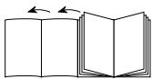
2.1.10 Check that the data plates are affixed to the appliance, if not, inform your dealer. Units without plates must NOT be used as they are unidentifiable and potentially dangerous. ACCIDENT HAZARD
2.1.11 DO NOT tamper with or adjust the setting of the safety valve or the safety devices. EXPLOSION HAZARD
2.1.12 DO NOT alter the original diameter of the spray head nozzle. HAZARDOUS ALTERATION OF OPERATING PERFORMANCE
2.1.13 DO NOT leave the appliance unattended. ACCIDENT HAZARD
2.1.14 DO NOT move the appliance by pulling on the ELECTRICAL CABLE. SHORT CIRCUIT HAZARD
2.1.15 Make sure that cars do not drive over the high pressure hose.
2.1.16 DO NOT move the appliance by pulling on the high pressure hose. EXPLOSION HAZARD
2.1.17 When directed towards tyres, tyre valves or other pressurised components, the high pressure jet is potentially dangerous. Do not use the rotating nozzle kit, and always keep the jet at a distance of at least 30~cm during cleaning. EXPLOSION HAZARD
2.2 SAFETY "MUSTS"
2.2.1 All electrical conductors MUST BE PROTECTED against the water jet. SHORT CIRCUIT HAZARD
2.2.2 The appliance MUST ONLY BE CONNECTED to an adequate power supply in compliance with all applicable regulations (IEC 60364-1). ELECTRIC SHOCK HAZARD

The appliance may cause network noise DURING startup.
- Use of a safety residual current circuit-breaker (R.C.C.B.) will provide additional protection for the operator (30 mA). Models supplied without plug must be installed by qualified staff. Use only authorized electrical extension leads with suitable conductor gauge.
2.2.3


High pressure may cause parts to rebound: wear all the protective clothing and equipment needed to ensure the operator's safety. INJURY HAZARD
2.2.4

Before doing work on the appliance, REMOVE the plug. ACCIDENTAL START-UP HAZARD
2.2.5

Before pressing the trigger, GRIP the gun firmly to counteract the recoil. INJURY HAZARD
2.2.6

COMPLY WITH the requirements of the local water supply company. According to EN 12729 (BA), the only be connected to the mains drinking water low preventer valve with drain facility is installed in CONTAMINATION HAZARD
appliance may only be connected to the mains drinking water supply if a backflow preventer valve with drain facility is installed in the supply hose. CONTAMINATION HAZARD
2.2.7

Maintenance and/or repair of electrical components MUST be carried out by qualified staff. ACCIDENT HAZARD
2.2.8

DISCHARGE residual pressure before disconnecting the unit hose. INJURY HAZARD
2.2.9

Before using the appliance, CHECK every time that the screws are fully tightened and that there are no broken or ts. ACCIDENT HAZARD
2.2.10


ONLY USE detergents which will not corrode the coating materials
of the high pressure hose/electrical cable. EXPLOSION AND ELECTRIC SHOCK HAZARD
2.2.11

ENSURE that all people or animals keep a minimum distance of 16 yd. (15m) away. INJURY
HAZARD
3 GENERAL INFORMATION (FIG.1)
3.1 Use of the manual
This manual forms an integral part of the appliance and should be kept for future reference. Please read it carefully before installing/ using the unit. If the appliance is sold, the Seller must pass on this manual to the new owner along with the appliance.
3.2 Delivery
The appliance is delivered partially assembled in a cardboard box. The supply package is illustrated in fig.1.
3.2.1 Documentation supplied with the appliance
A1 Use and maintenance manual
A2 Safety instructions
A3 Declaration of conformity
A4 Warranty regulations
3.3 Disposing of packaging
The packaging materials are not environmental pollutants but must still be recycled or disposed of in compliance with the relevant legislation in the country of use.
3.4 Safety signs
Comply with the instructions provided by the safety signs fitted to the appliance.
Check that they are present and legible; otherwise, fit replacements in the original positions.
E1 sign - Indicates that the appliance must not be disposed of as municipal waste; it may be handed in to the dealer on purchase of a new appliance. The appliance's electrical and electronic parts must not be reused for improper uses since they contain substances which constitute health hazards.
3.4.1 Symbols

E2 symbol - Indicates that the appliance is intended for professional use, i.e. for experienced people informed about the relative technical, regulatory
and legislative aspects and capable of performing the operations necessary for the use and maintenance of the appliance.

E3 symbol - Indicates that the appliance is intended for non-professional (domestic) use.
4 TECHNICAL INFORMATION (FIG.1)
4.1 Envisaged use
This appliance has been designed for individual use for the cleaning of vehicles, machines, boats, masonry, etc, to remove stubborn dirt using clean water and biodegradable chemical detergents.
Vehicle engines may be washed only if the dirty water is disposed of as per regulations in force.
- Intake water temperature: see data plate on the appliance.
- Intake water pressure: min. 0,1MPa-max 1MPa.
- Operating ambient temperature: above 0^ .
The appliance is compliant with the EN 60335-2-79/A1 standard.
4.2 Operator
The symbol on the front cover identifies the appliance's intended operator (professional or non-professional).
4.3 Improper use
Use by unskilled persons or those who have not read and understood the instructions in the manual is forbidden.
The introduction of inflammable, explosive and toxic liquids into the appliance is prohibited.
Use of the appliance in a potentially inflammable or explosive atmosphere is forbidden.
The use of non-original spare parts and any other spare parts not specifically intended for the model in question is prohibited.
All modifications to the appliance are prohibited. Any modifications made to the appliance shall render the Declaration of Conformity null and void and relieve the manufacturer of all liability under civil and criminal law.
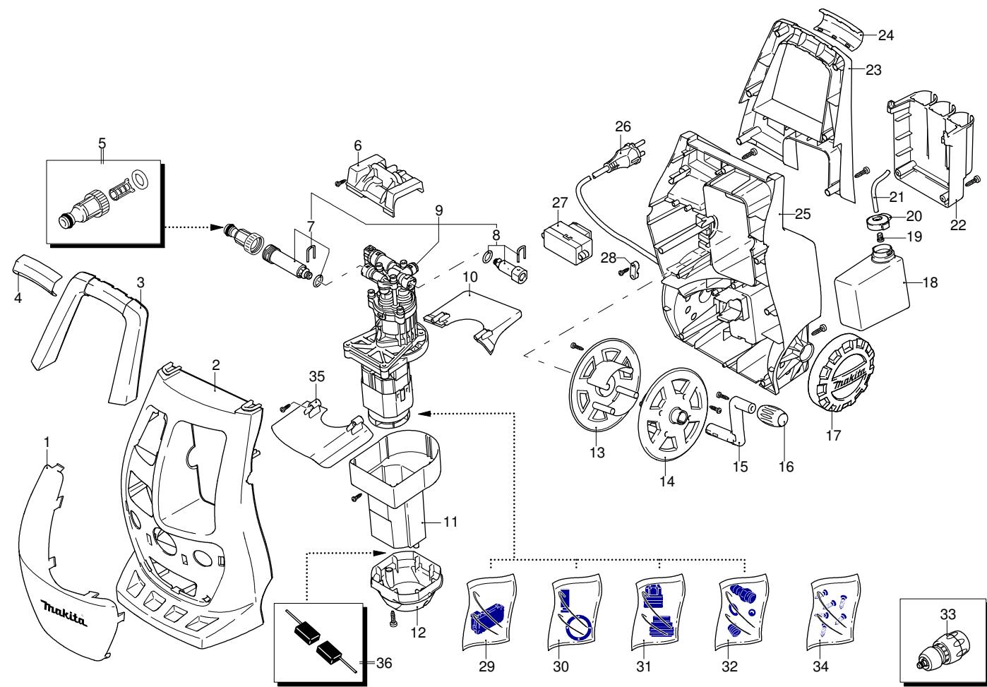
4.4 Main components (see fig.1)
B1 Adjustable spray nozzle
B2 Lance
B3 Gun with safety catch
B4 Power supply cable with plug
B5 High pressure hose
B6 Detergent tank
4.4.1 Accessories
C1 Nozzle cleaning tool
C2 Rotating nozzle kit
C3 Handle
C4 Brush (on models with this feature)
C5 Hose reel (on models with this feature)
4.5 Safety devices
Caution - Danger! Do not tamper with or adjust the safety valve setting.
- Safety valve and/or pressure limiting valve.
The safety valve is also a pressure limiting valve.
When the gun trigger is released, the valve opens and the water recirculates through the pump inlet.
- Safety catch (D): prevents accidental spraying of water.
5 INSTALLATION (FIG.2)
5.1 Assembly
Caution - Danger! All installation and assembly operations must be performed with the appliance disconnected from the mains power supply.
The assembly sequence is illustrated in fig.2.
5.2 Assembling the rotating nozzle
(For models with this feature)
The rotating nozzle kit delivers greater washing power.
Use of the rotating nozzle may cause reduction in pressure of 25% compared to the pressure obtained with the adjustable nozzle. However, the rotating nozzle kit delivers greater washing power due to the rotation of the water jet.
5.3 Electrical connection
Caution - Danger! Check that the electrical supply voltage and frequency (V-Hz) correspond to those specified on the appliance data plate (fig.2). The appliance should only be connected to a mains power supply equipped with an adequate earth connection and a differential security breaker (30mA) to cut off the electricity supply in the instance of a short circuit.
5.3.1 Use of extension cables Use cables and plugs featuring "IPX5" protection level. The cross-section of the extension cable should be proportionate to its length; the longer it is, the greater its cross-section should be. See table I.
5.4 Water supply connection
Caution - Danger! Only clean or filtered water should be used for intake. The delivery of the water intake tap should be equal to that of pump capacity.
Place the appliance as close to the water supply system as possible.
5.4.1 Connection points
Water outlet (OUTLET)
Water inlet with filter (INLET)
5.4.2 Connection to the mains water supply
The appliance can be connected directly to the mains drinking water supply only if the supply hose is fitted with a backflow preventer valve as per current regulations in force. Make sure that the hose is at least 0.13mm and that it is reinforced.
6 ADJUSTMENT INFORMATION (FIG.3)
6.1 Adjusting the spray nozzle (for models with this feature) Water flow is adjusted by regulating the nozzle (E).
6.2 Adjusting the detergent (on models with this feature) Detergent flow is adjusted using the regulator (F).
6.3 Adjusting the detergent pressure Set the adjustable nozzle (E) on " " to deliver detergent at the correct pressure (on models with this feature).
6.4 Adjusting the pressure (on models with this feature) The regulator (G) is used to adjust the working pressure. The pressure is shown on the pressure gauge (where fitted).
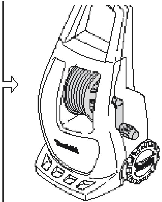
7 INFORMATION ON USE OF THE APPLIANCE (FIG.4)
7.1 Controls
-
Starter device (H).
-
Set the starter switch on (ON/1) to set the motor ready to start.
- Set the starter device switch on (OFF/0) to shut down the appliance.
-
- Water jet control lever (I).

Caution - Danger!
During operation the appliance must be positioned down in fig. 4 on a sturdy, stable surface.
7.2 Start-up
1) Turn on the water supply tap fully.
2) Release the safety catch (D).
3) Depress the gun trigger for a few seconds and start up the appliance using the starter device (ON/1).

Caution - Danger!
Before starting up the appliance check that the water supply hose is connected properly; use of the appliance without water will damage it; do not cover the ventilation grilles when the appliance is in use.
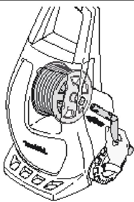
TSS models - In TSS models with automatic delivery flow cut-off system:
- when the gun trigger is released the dynamic pressure automatically cuts out the motor (see fig.4);
- when the gun trigger is depressed the automatic drop in pressure starts the motor and the pressure is restored after a very slight delay;
- if the TSS is to function correctly all gun releasing and depressing operations must be performed at intervals of less than 4-5 seconds.
To prevent damage to the appliance, do not allow it to operate dry.
7.3 Stopping the appliance
1) Set the starter device switch on (OFF/0).
2) Depress the gun trigger and discharge the residual pressure inside the hoses.
3) Engage the gun safety catch (D).
7.4 Restarting
1) Release the safety catch (D).
2) Depress the gun trigger and discharge the residual air inside the hoses.
3) Set the starter device on (ON/1).
7.5 Storage
1) Switch the appliance off (OFF/0).
2) Remove the plug from the socket.
3) Turn off the water supply tap.
4) Discharge the residual pressure from the gun until all the water has come out of the nozzle.
5) Drain and wash out the detergent tank at the end of the working session. To wash out the tank, use clean water instead of the detergent.
6) Engage the gun safety catch (D).
7.6 Refilling and using detergent
When using detergent, the adjustable nozzle must be set on " " (on models with this feature).
Use of a high pressure hose longer than the one originally supplied with the cleaner, or the use of an additional hose extension, may reduce or completely halt the intake of detergent. Fill the tank with highly degradable detergent.
7.7 Recommended cleaning procedure
Dissolve dirt by applying the detergent mixed with water to the surface while still dry.
When dealing with vertical surfaces work from the bottom upwards. Leave the detergent to act for 1-2 minutes but do not allow the surface to dry. Starting from the bottom, use the high pressure jet at a minimum distance of 30~cm . Do not allow the rinse water to run onto unwashed surfaces.
In some cases, scrubbing with brushes is needed to remove dirt. High pressure is not always the best solution for good washing results, since it may damage some surfaces. The finest adjustable nozzle jet setting or the rotating nozzle should not be used on delicate or painted parts, or on pressurised components (e.g tyres, inflation valves, etc.).
Effective washing depends on both the pressure and volume of the water used, to the same degree.
8 MAINTENANCE (FIG.5)
Any maintenance operations not covered by this chapter should be carried out by an Authorized Sales and Service Centre.

Caution - Danger!
Always disconnect the plug from the power socket to the carrying out any work on the appliance.
8.1 Cleaning the nozzle
1) Disconnect the lance from the nozzle.
2) Remove any dirt deposits from the nozzle hole using the tool (C1).
8.2 Cleaning the filter
Inspect the intake filter (L) and detergent filter (if fitted) before each use, and clean in accordance with the instructions if necessary.
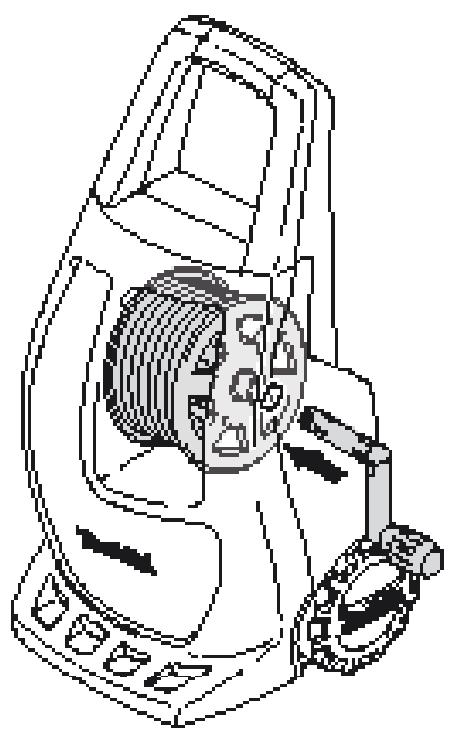
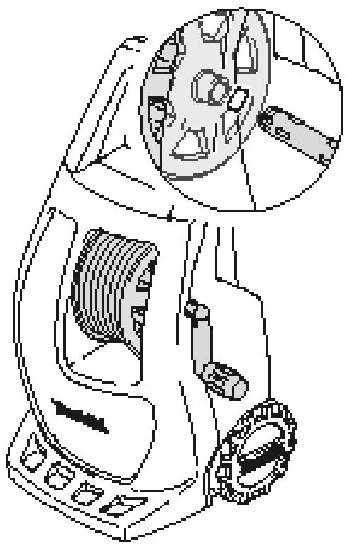
8.3 Unjamming the motor (on models with this feature)
In case of lengthy stoppages, limescale sediments may cause the motor to seize. To unjam the motor, turn the drive shaft with a tool (M).
8.4 End-of-season storage
Treat the appliance with non-corrosive, non-toxic antifreeze before storing it away for winter.
Put the appliance in a dry place, protected from frost.
9 TROUBLESHOOTING
| Problem | Possible causes | Remedy |
| Pump does not reach working pressure | Nozzle worn | Replace nozzle |
| Water filter fouled | Clean filter (fig.5) | |
| Water supply pressure low | Turn on water supply tap fully | |
| Air being sucked into system | Check tightness of hose fittings | |
| Air in pump | Switch off the appliance and keep depressing and releas-ing the gun trigger until the water comes out in a steady flow. Switch the appliance back on again. | |
| Adjustable nozzle not positioned correctly | Turn the adjustable nozzle (E) (+) (fig.3) | |
| Thermostatic valve tripped | Wait for correct water temperature to be restored | |
| Pressure drops during use | Water intake from external tank | Connect appliance to the mains water supply |
| Intake water too hot | Reduce temperature | |
| Nozzle clogged | Clean nozzle (fig.5) | |
| Intake filter (L) dirty | Clean filter (L) (fig.5) | |
| Motor "sounds" but fails to start | Insufficient power supply | Check that the voltage of the mains power supply line is the same as that on the plate (fig.2) |
| Voltage loss due to use of extension cable | Check characteristics of extension cable | |
| Appliance not used for a long period of time | Contact your nearest Authorized Service Centre | |
| Problems with TSS device | Contact your nearest Authorized Service Centre | |
| Motor fails to start | No electrical power | Check that the plug is firmly in the socket and that the mains voltage supply is present (*) |
| Problems with TSS device | Contact your nearest Authorized Service Centre | |
| Appliance not used for a long period of time | Using the tool (M) unjam the motor from the hole at the rear of the appliance (in models with this feature) (fig.5) | |
| Water leakage | Seals worn | Have the seals replaced at your nearest Authorized Service Centre |
| Safety valve tripped and discharging | Contact an Authorized Service Centre | |
| Appliance noisy | Water too hot | Reduce temperature (see technical data |
| Oil leakage | Seals worn | Contact your nearest Authorized Service Centre |
| TSS versions only: motor starts even with gun trigger is released | High pressure system or pump hydraulic circuit not watertight | Contact your nearest Authorized Service Centre |
| TSS versions only: no water delivery when gun trigger is depressed (with supply hose connected) | Nozzle clogged | Clean nozzle (fig.5) |
| No detergent taken in | Adjustable nozzle on high pressure setting | Set nozzle on " " setting (fig.5) |
| Detergent too dense | Dilute with water | |
| High pressure hose extension being used | Fit original hose | |
| Deposits or restriction in detergent circuit | Flush with clean water and eliminate any restrictions. If the problem persists, contact an Authorized Service Centre |
(*) If the motor starts and does not restart during operation, wait 2-3 minutes before repeating the start-up procedure (overload cutout has been tripped). If the problem recurs more than once, contact your nearest Authorized Service Centre.
| Technical Data (EN) | Unit | HW111 |
| Output | L/min | 6,2 |
| Pressure | MPa | 9 |
| Maximum pressure | MPa | 11 |
| Power | kW | 1,7 |
| T° input | °C | 50 |
| Maximum input pressure | MPa | 1 |
| Repulsive force of the gun to the maximum pressure | N | 13,6 |
| Motor Insulation | - | Class F |
| Motor Protection | - | IPX5 |
| Voltage | V/Hz | 230/50 |
| Sound level K = 3 dB(A): | ||
| L_PA (EN 60704-1) | dB (A) | 79,15 |
| LWA (EN 60704-1) | dB (A) | 87 |
| Unit vibrations K = 1,5 m/s2: | m/s2 | 3,72 |
| Weight | kg | 7,4 |
MODEL
SERIAL NUMBER
EN EC Declaration of conformity
We Makita Corporation, Anjo, Aichi, Japan declare that the following Makita Machine(s):
Designation of Machine
High Pressure Washer
Model No /Type
HW111
Input power
1,7 kW
Conforms to the following European Directives:
2006/42/EC, 2006/95/EC, 2002/95/EC, 2002/96/EC, 2004/108/EC, 2000/14/EC
And are manufactured in accordance to the following standards or standardised documents: EN 60335-1; EN 60335-2-79; EN 55014-1; EN 55014-2; EN 61000-3-2; EN 61000-3-3; EN 61000-3-11; EN 60704-1
The Technical Documentation is kept by our authorised Representative in Europe who is:
Makita International Europe Ltd,
Michigan, Drive, Tongwell,
Milton Keynes, MK15 8JD, England
The conformity assessment procedure required by Directive 2000/14/EC was in accordance with annex V
Measured Sound Power Level L_PA : 86 dB (A); (K=3 dB(A)
Guaranteed Sound Power Level L_WA : 87 dB (A); (K = 3 dB(A)
06th December 2010

Kato Tomoyasu
Director
Makita Corporation, 3-11-8 Sumiyoshi-Cho, Anjo, Aichi, 446-8502, Japan
2 SICHERHEITSVORSCHRIFTEN/RESTGEFAHREN
2.1 WARNHINWEISE: UNZULÄSSIG
Michigan, Drive, Tongwell,
Milton Keynes, MK15 8JD, England
2006/42/CE, 2006/95/CE, 2002/95/CE, 2002/96/CE, 2004/108/CE, 2000/14/CE
Michigan, Drive, Tongwell,
Milton Keynes, MK15 8JD, Inghilterra
2006/42/CE, 2006/95/CE, 2002/95/CE, 2002/96/CE, 2004/108/CE, 2000/14/CE
Michigan, Drive, Tongwell,
Milton Keynes, MK15 8JD, Inglaterra
5 INSTALAÇAO (FIG.2)
5.1 Montagem
Atenção-perigo!
2006/42/CE, 2006/95/CE, 2002/95/CE, 2002/96/CE, 2004/108/CE, 2000/14/CE
Michigan, Drive, Tongwell,
Milton Keynes, MK15 8JD, Inglaterra
2006/42/EK, 2006/95/EK, 2002/95/EK, 2002/96/EK, 2004/108/EK, 2000/14/EK
kai napayetai(ovta) ouqwva ta akoloutheta npotuna n ta akoloutheta tunonoineva
éyyραφα: EN 60335-1; EN 60335-2-79; EN 55014-1; EN 55014-2; EN 61000-3-2; EN 61000-
3-3; EN 61000-3-11; EN 60704-1
Ta texvika éyypaqa φuλáσσονtaui σtnv éδpa tou εξουσιδoτημέvou avπipooωπou μac σtny Eupωπη:
Makita International Europe Ltd,
Michigan, Drive, Tongwell,
5 INSTALLATIE (FIG.2)
5.1 Montage
Let op - gevaar!
Michigan, Drive, Tongwell,
Milton Keynes, MK15 8JD, England
Makita Corporation, 3-11-8 Sumiyoshi-Cho, Anjo, Aichi, 446-8502, Japan
1 SIKKERHEDSREGLER
INSTALLATION (FIG. 2)
5.1 Montering
8.4 Opbevaring for winter
Lad maskinen kore med/DDke tarende eller gfitig frostvase, for maskinen saettes til opbevaring for vinteren.
2006/42/EF, 2006/95/EF, 2002/95/EF, 2002/96/EF, 2004/108/EF, 2000/14/EF
Michigan, Drive, Tongwell,
Milton Keynes, MK15 8JD, Storbritannien
8 VEDLIKEHOLD (FIG. 5)
2006/42/EF, 2006/95/EF, 2002/95/EF, 2002/96/EF, 2004/108/EF, 2000/14/EF
Michigan, Drive, Tongwell,
Milton Keynes, MK15 8JD, Storbritannien
4 TEKNISET TIEDOT (KUVA 1)
4.1 Käytötarkoitus
2006/42/EY, 2006/95/EY, 2002/95/EY, 2002/96/EY, 2004/108/EY, 2000/14/EY
Michigan, Drive, Tongwell,
Milton Keynes, MK15 8JD, England
Makita Corporation, 3-11-8 Sumiyoshi-Cho, Anjo, Aichi, 446-8502, Japan
1 SÄKERHETSBESTÄMMELSER
3 ALLMÄN INFORMATION (FIG. 1)
5 INSTALLATION (FIG.2)
5.1 Montering
Varning-fara!
Michigan, Drive, Tongwell,
Milton Keynes, MK15 8JD, Storbritannien
Makita Corporation, 3-11-8 Sumiyoshi-Cho, Anjo, Aichi, 446-8502, Japan
1 BEZPECNOSTNI POKNY
2.1 ZAKAZANE CINNOSTI
2.2 POVINNE CINNOSTI
2006/42/ES, 2006/95/ES, 2002/95/ES, 2002/96/ES, 2004/108/ES, 2000/14/ES
Michigan, Drive, Tongwell
2006/42/WE, 2006/95/WE, 2002/95/WE, 2002/96/WE, 2004/108/WE, 2000/14/WE
Michigan Drive, Tongwell,
Milton Keynes, MK15 8JD, England
Makita Corporation, 3-11-8 Sumiyoshi-Cho, Anjo, Aichi, 446-8502, Japan
1 VARNOSTNA NAVODILA
2006/42/ES, 2006/95/ES, 2002/95/ES, 2002/96/ES, 2004/108/ES, 2000/14/ES
in je (so) izdelan(i) v skladu z naslednjimi standardi oziroma normativnimi dokumenti: EN 60335-1; EN 60335-2-79; EN 55014-1; EN 55014-2; EN 61000-3-2; EN 61000-3-3; EN 61000-3-11; EN 60704-1
Michigan, Drive, Tongwell,
Milton Keynes, MK15 8JD, England
Makita Corporation, 3-11-8 Sumiyoshi-Cho, Anjo, Aichi, 446-8502, Japan
1 BEZPECNOSTNE POKNY
9 RIESENIE PROBLEMOV
2006/42/ES, 2006/95/ES, 2002/95/ES, 2002/96/ES, 2004/108/ES, 2000/14/ES
A vyrába sa v súlade s nasledujúcimi normami alebo normativnymi dokumentmi: EN 60335-1; EN 60335-2-79; EN 55014-1; EN 55014-2; EN 61000-3-2; EN 61000-3-3; EN 61000-3-11; EN 60704-1
Michigan, Drive, Tongwell,
Milton Keynes, MK15 8JD, Anglicko
Michigan, Drive, Tongwell,
Milton Keynes, MK15 8JD, England
Makita Corporation, 3-11-8 Sumiyoshi-Cho, Anjo, Aichi, 446-8502, Japan
1 INHCTPYKUIMN3A B6E3ONACHOCT
1.1 YpeDbT, KOIO TCE 3aKynnn, npeCTabIbBA npOdyKT c abAHrapHaTexHOJIOrn, npoEeTIpaH ON t EINH OT BOeUHTe EBPOeNCKn pOni3BODITEN Ha NOMN C BVCOKO HANrAHe. 3a da NpOyNTe HAI-Do6Pi NOKa3ATEH NaP6Ota OT BAuH yPeD, npOHTeTE BHNMaTeHNO Ta3N KNJXKA u CJIeDBAITE INCTpyKUnITE BCEKN PbT, KOrATO rO I3NoI3BaTe. P03dPaRbAMe BN 3a BAuH N36Op n BN XKeJaEM ycpeHa pa6ota.
2 IPNABUNIA 3A B630NACHOCT/OCTATbHIN PNCKOBE
2.1 HEIONYCTM0 OT TJIEDHA TOKA HA BE3OJACHOCTTA
2.1.1 HE n3no3BaTe ypea cbc 3anaJIteHn nn TOKcHn
TeuHOTn NIN PNOyKTN, KOINTo HE Ca CbBMECTMN C npabUNHaTa pa6Ota Ha ypeDa. ONACHOT ONT3bYBAHE NIN OTPABHE
2.1.2 HE HacouBaIte BOHnata CTpykBm Xopa IIN JNIBOTHNI. ONACHOCT OT HAPAHABAHE
2.1.3 HE haoCuaBte BoDHaTa Ctpy KaM CaMna ypei, eJekTpUeCKnTe qactn nn KbM dpyra eJekTpUeCKa anapatypa. ONACHOCT OT YAPC EJEKTpUeCKn TOK
2.1.4 HE n3pOJ3BaIte ypeDa Ha oTKpIto, KOraTo BaJI. OnACHOCT OT KbCO CbEINHEHIE
2.1.5 HE no3BovIaBaiTe Ha deca nn HemoiHn Iina da n3PON3BaT MaunHaTa 3a NoHCCTBaHe. ONaCHOCT OT HAPAHABAHE
2.1.6 HEdoKocBaIte uIeCena n/IIIN KOHTaKtCa MOKpN pBue. ONACHOCT OYJAP C ENEKTPNUeCKN TOK
2.1.7 HE n3non3BaIte ypeDa, aKo eJeleKTPnueCKnT Ka6en e NOBpeHc. ONaCHOCT OT YdAP C EJEKTPNUECKN TOK KbCO CbEINHEHIE
2.1.8 HE u3nOJ3BaiTe ypea, aKO mapKyuT 3a BUCOKo HalaIraHe e noBpeJeH. OAnCHOCT OT u36yXBaHE
2.1.9 HE 6nokpaTe cnycbKa B pa6oTHO noloxeHne. ONACHOCT OT 3JIOJNYKA
2.1.10!PpOBepe TaJIi TaBeknIe C DaHnn Ca 3aKpeHn 3a ypeJa.AKO He ca, YbeDomete DoCTabNtka cn.YctpoCTBa 6e3 TaBeknI HE Tpa6Ba da Ce I3no3BaT, Tb' KATO Te He Moar da Ce UdENTnΦuCmP aT nCa notenuaHIO onaChi. OAnCHOCT OT 3JOnOlyKa
2.1.11 He ninnaiTe u He peryunpaaiTe hactpoinkte Ha o6e3onacntenHnKJanaan nn Obe3onacntenHnTe yCTpOoiCTBa. ONACHOCT OT N3BXXAHE
2.1.12 HE npomehyte opunnaHnHaIHa nAmeTbp Ha IIO3aHa HnakpaHnKa 3a ctpyTa. ONACHO N3MEHEHNE HA PABOTHNE
2.1.13 HE octabayte ypea 6e3 na30p. OIaCHOCT OT 3IOIOnyKA
2.1.14 HE npemeCTBaIte ypea upe3 dIbPnahe 3a eIeKtpnuecknKa6eI. ONACHOCT OT KbCO CbEINHEHIE
2.1.15 BhIMabai Te Bbpy MaKpya 3a BcOko HnlaIaHe da He npemHabat KOJI.
2.1.16 He npnDbnKbAte ypea c DbpnaHe Ha Mapkya noD BnCOKO HAIraHe. ONACHOCT OT N3bYXBAHE
2.1.17 HacoubaheTo Ha cTpy nOd BncoKo HnlaRanHe KbM rymu, BeHTnIHa rymu n DpyrN KOMNoHEtN nOd HnlaRanHe MOKe da 6bDe OAnCHO.He n3noI3BaIte Ha6opa ot Bbptraui Ce hakpaHnui n BuHaRn dpbXte cTpyTa Ha pa3ctoHne ot nohe 30 cm no Bpeme Ha nouchTbaHeTo. OAnCHOCT ONT N3bYXBAE
2.2 3AДьЖИTEЛNO 3A OCSIGNYPRABAHE HA BE3OПАCHOCT
2.2.1 Bcunkn eJektpnueckn npOboDnHnTPBBA DA bBdAT cb3aunita cpeu BOHa CTpy. ONaCHOCT OT KbCO CbEINHEHNE
2.2.2 YeBbT DA CE BKJIIOUBA CAMO KbM NOxOJaIO eJekTpO3aXpaHbAbe B cbOTBETCTBNE C BCINKNe DeiCTBaIHN HOPMaTINBHNI 3NcKBaHnR (IEC 60364-1). ONACHOT OT YJAP C EJEKTPNUECKN TOK
YpeBt Moze da npedn3Bnka cmyeHn Bmpexa TPNBkJIIOUcBaHe.
- I3nol3BaHeto Na npedna3eH npekcbau Ha Bepurata 3a OCTaTbueh ToK Ue OcNpyn DoNbHInTeHa 3aunita 3a onepatopa (30mA).
MoDenite 6e3 uecen Tp8bda 6bdat nHctanipahn ot KBaIIuΦuIpaH nepcoHAn.
U3noJI3BaIe cAmO oO6peH enEKeTpoyIbJxNITeIN C noDxOJaIu DnAmETbP hA npOBoHNka.
2.2.3
Bucokoto hana rhe MoKe Da DObeHe Do pKoUnpaHe Ha cactte: He6xoJIMMo e 3auTHO ObkeNo o6OpyDbaHe, KoTo da Ocnrgpyn 6e3onacHOCTTa Ha onepaTopa. OnACHOT OT HAPAHBAHE
2.2.4 Ппedi Nazочвае на pa6otn 3a obcnykbahe Bbpxu ypeda, N3BADETE uenceeta ot KOHTaKta. ONACHOCT ONCUYAHO
2.2.5 Ппedi Да Натисене суньka, CTИСКАЙTE пистоета 3драво, за длpoТИВОДЕйСТВATE Ha obpaTHNЯ TnaCbK. ONACHOCT OT HAPAHRBAHE
2.2.6 13ΠbJIHBAIte ΜιεικBαHητa Na MeCThata BOOCHa6dnteHnHa KOMNaHn. B CbOTBETCTBne c EN 12729 (BA), ypeβt MoJE da ce CBp3Ba KbM BOOpnpOBo3a ΜιTEHn BOJa, caMO aKO b MapKyuHa 3a NOdaBaHe e MOHTiPah Kλanahan Cpeuoy o6paTeH xOc yctpoiCTBO 3a n3εχdAne. ONACHOCT OT 3AMbPCABAE
2.2.7 Texnuecko 06cnykbahe w/wnppeMOHT Ha eNeKtpnueckn KOMNHOENTI TPR5BA Da ce n3BbprBa ot KBaINHnpuHa np cepoHaI. ONACHOCT OT 3JIOJNYKA
2.2.8 OCBOOJKDABAITE OCTaTbHOTo HajraHe, ppei da OTKaHTe Mapkya Ha ypeJa. ONACHOT OT HAPAHBAAHE
2.2.9!Ppei Da n3non3BaTe ypeia, PIOBEBPAIte Bcekn pbl DaIIIN BHTOBete ca 3aTeHnat IOKpaI N daII IN HMa CaYpEni nn 13HOCEHn qactn. ONAHOCT OT 3JNOJyKA
2.2.10 ! N3PONJ3BAIITE cMoTepeTHTN KOINTO He pIeIN3BKNKbAT KOPOINHa MATEPNAJIITHe HnOKPNIITNeTo Ha MapKUa 3a BVCOKo HnJIraHc/ eNEKTPMueCKN Ka6eI. OAnACHOCT OT IN36YXBAEu NDAP C EJEKTPNUECKN TOK
2.2.11 OCINIYPRBAITE OTdaneueheOCT Ha BCNUKxopa IINJXIBOTHN Ha pa3ctOraHne MInHMym 15 MeTpa. ONACHOCT OT HAPAHABAHE
3 ObuCBEHNE (ΦNΓ.1)
3.1 ⅢπολBaHepbkoBODCTBOTO
Hactoio pkoBDCTBO npctablaBa Hejima qacT ot ypea n Tpa6ba Da ce na 3a 6bdeu CnpBk. Ipouetete ro BnmatenHO, npdi da nHctalnPate/3nON3BaTe yCtpoiCTBO.ToPi npOdaJkaHa ypea PpOdaBaYt Tpa6ba Da npede TaTOBa pkoBDCTBO Ha HOBn Co6CTBeHN 3aeHNO Cypea.
3.2 Ooctabka
UpebTcdoCTaBAyCACTNUHO CrtIO6eB B KApTOHeHa KUTNA.
Onakobkatae mIIOCTpnpaHa hIg.1
3.2.1 Dokymenu, npudpykabaui ypeda
A1 PboDcTb 3a ynoTpe6n noDpKka
A2 IHTpykUm 3a6e3oNaCHOCT
A3 Deknapaunzra 3cbOTBeTCTBNE
A4 YcnoBmHa rapaHunra
3.3 IxBbPJIHe Ha onaKOBbYHnTe MaTePnAJIi
OnakOBbUHNTe MaTePmaJIne He 3aMbPCBAt BOKIIHATA CpeIa, HO BbIpeKIN TOBa Tp8Ba Da ce daat 3a peuKlnpaHe mIa De cI3XbBpIaT B CbOTBeTCTBnE CdeICTBaUata HOpMaTbHbA ype6Ba B CTpaHaTa Ha yNtpe6a.
3.4 3naun3a6e3oNaCHOCT
CnabaIte INHCTpykUInTe, yka3aHN Ha 3HaunTe 3a 6e3oNaCHOCT, nocTaben Hbpxy ypeda.
Ybepete ce,Ye ta HauHnH uTINB; B npotmben CnyaH noCTabete HOBN TAKIBa Ha IpbBOHaayAHInTE IM MeCTa.
3NaK E1 - Poka3Ba, YepeBt He Tp6Ba Da ce N3XbPnC 6ntoBte OTnAbTu; MoKe Da 6bDe BbpHata Ha DnIbpa Prn NOKyNka Ha HOB ypeD. EneKtpuuecknte n EneKtpoHH uactn Ha ypeDa He 6bMa Da 6bDat I3No3BaHn NOBtropHO 3a HenoJxoJaUcEJI, Tb Kato CbDbPxat BeueCTBA, KOTo IpeDctabJrBAT OAnCHOCT 3dPaBeTO.
3.4.1 Cumbolu

CmBbON E2 - O3Haaba, Ye ypeBt e npedHa3aeh 3a npopecnoHaHa ynToPe6a, Toec 3a onnTHn Xopa, HnFopMnpaHn 3a OTHCINTeHNITE TExNHuecKm, peryNaTOpHn
I 3aKoHOBN acNeKTn, n CnOcObH na I3BbpiBaT pIoceDpytne, Heo6xOJIMM 3a I3NoI3BaHETo IO npDbpXkata Ha ypeA.

CmBON E3 - O3NaHABA, Ye ypeDt e npdeHa3Naueh 3a HeippofeecnoHaHa (DomaHa) ynoTpe6a.
4 TEXHnueCKA HNΦOPMALJIA (ΦNΓ.1)
4.1 PpEHa3NaeHne
To3u ypei e npedna3aueh 3a HnDnBnDyAnHa yNtpe6a 3a noCCTBaHe Ha ABTOMO6bIMn, MaSINHn, IOnkN, CTeHn n dp., C cen OTcpanBaHe Ha yOpNTn 3aMbpCRBaHnA, KaTO n3PON3BA YnCTa BODa N bOpap3rpaJdaunCe XmMnueckn DeTeprHTN.
Bniratne Ha ABTOMO6NI MOrAT da Ce noUCTBaT cAmO aKO ce n3NoJI3Ba HEniTeHa BODA B CbOTBeTcBNE C DeIeCTBaUaTATA HOpMaTHBA Ype6a.
- TemnepaTpa Ha IIOeMaHaTa BODa: BIX Ta6eKata C TexHmYeCKn DaHHn Ha ypeDa.
HanaheHa noemaHaTa Boda: no106apa.
CmykateHNO hajrahe 3a BOda: MmH.0,1MPa-makc.1MPa.
YpeBt Cb0TBeCTBa Ha CTaHApT EN 60335-2-79/A1.
4.2 Oneparot
CmBbnt Ha npednna Kanaak OnpeDena 3a KaKbB OnepatOp e npedHa3Naehyepdt (npoecnoHannCT nnn HnepoecnoHannCT).
4.3 Ynotpe6a He no npedHa3HaueHne
3a6paheena e ynoTepeBaTa O T hKbAinHmIupaHn Iina q HnO T KaNBA, KOITo He ca npoueHn pa36paHn INhctpykUInTe B pkbKOBOCTBOTO.
3a6paHHe e b ypeDa ca Ce nOCTaBRT Bb3PnAmeHmMn, B3pNBOOnaChn INTOKCMHN TeHOCNT.
3a6paheHa e pa6oTaTc cypea B nOteHnnaHIO Bb3PnAmEHMa NIN B3pNBOONacha aTMocphi.
I3noJ3BaHTo Ha HeOpUInHaHn Pe3epBn 卅CTn I dpyr n pe3epBn qactn, KOtHO He Ca KOHNpEJaHaHaeHn 3a BbnpOHHoMeJ, e 3abpaHeNo.
3a6paheNo e da ce n3bBpWBat KaKBInTo m Da 6nlo MoDnΦkaun Ha ypeDa. BcakBn MOnΦkaun, n3BbPweHn Bbpxy ypeA, o6e3CnBnat an Anynipat DeKnapaunraTa 3a CbTOBETCTBne I NCBO6OJabat PpOn3BOJntel T OBCAKBa OTROBOPHOCT NO rpaXdAnCKOTu Haka3aTeHOTO npabo.
4.4 IaBHH KOMNoHEHTn (6x.hu2.1)
B1 Peryunpyem hakpaHnK cI03a
B2 YdblnJHtEnHa Tp6a
B3 nctonet c npednataen
B4 3axpaanbaa ka6eI c quencen
B5 Mapkyu 3a Bucko Hana rane
B6 Pe3epBoaop 3a detepreHT
4.4.1 Akcecoapu
C1 Pnp6op 3a nouchtaBe Ha JIO3aTa
C2 KOMJIeKT BbptTc Ce hakpaHnIK
C3 DpBka
C4 YeTka (npn moJeIN c TOba npncnoCo6JeHne)
C5 Polka 3a Mapky (npm mojein c ToBa npncnocobneHne)
4.5 PtpednataHn yctpoiCtBa

Bhumahue - onachocm!
He npomennIte n He perynipaiTe hactpoikata Ha npedna3nH
- 06e3oNaCtTeHEN BHTINn n/nn orpaHnUaBaAs HAJIraHETO BHTIN.
PepnataHnT Klaanah e n Klaanah 3a OrpauhabaHa h HalaheTo. Pnocbo6oxdaBaHa hCKycbKa BHTinbTe Ce OTBpa N BODa T3BbPwaPeuPKyuaia Ppe3 BXOHa Ha NOMnata.
-П配电网电(D):преторватая сухаимото пьскане на Вобд.
5 INHCTAJIMPAHE (ФИГ.2)
5.1 MoThax

Bhumahue - Onachocm!
BcunkOnepaunNoHnctanipaneNMOtack Tpa6Ba da ce HbAT, KORATO ypeDbTe n3KniUoeh OT enekTpo3axpaHbAHeTo.
MOttaKhata nocIeIobateJIHOCT e NIOCTpnpaHa HaΦn.2.
5.2 MoNTIpaHa He BbptTiaHc HauPaHHK
(3a mojenei c ToBa npicnoc6neHne)
KOMPKNKTbBPTaCeHaKpAHHK OCSIRpyBaNo-rofA MaOuHcCT HaN3MMBaHe. N3ON3BaHTo Ha BpTaAaCe HApAHHK MoKe Da npuHH Do 25% cnaDaHe Ha HAnraHTo, B CpaBHeHne C TOBA pRn U3NON3BaHae Ha peryInpyEm HApaiHnK.
KOMPJIeKTbBpTtIcHakpAHmI,Oaue,DabaNo-roJIaMa TbBkABoCT npMnHe Nopadn BpTeHETo Ha BOdHaTcTpy.
5.3 Cbpb3BaHe KbM eJeleKtpueeckaTa Mpeka

Bhumahue - Onachocm!
!Поберете дами habржимeto n checotata (V - Hz) ha ekeTPOCHa6dntelhata mpeka OTOBAPAT Ha cToHIOCTYte, nocouhen Ha ta6eJkata Ha ypeda (ФИR.2).UpebI Tp6Ba da ce Cbpb3Ba cmo KbM mpeko ekeTPO3axpaHBAne, ch6deHo c npdojIo 3a3emBaHe m dipepenuaneh 3auitien ppekbcva H beprata (30 mA), 3a da ce ppeKbche noDaabaHTo Ha napejHnE B ClyuaH Na Kbco cbJeHnEHnE.
5.3.1 I3non38ahe ha yobjxumennku6enu
U3non3BaWte Ka6eN u 7cHbO Ha 3aunita IPX5.
HanpehHOTo ceeHHe Ha npOBoHNka Ha yIbJxNtENHnKa 6aen Tp8Ba Da bIe CbTOBteHO Ha nbJxHnHaT My - pN no-ToJMa HblxHnHa HanpehHOTo ceeHHe Tp8Ba Da e no-ToJMaO. Bx. tabNiuaI.
5.4 Cbpb3BaHe KbM BOJOpPBOBa

Bhumahue - Onachocm!
Ipoaabahata BODa MOKe Ja 6bJe cAmo UcTa NnN fHHTpnpHa. De6bTb Ha KpaHa 3a PoabAHe Ha BODa Tp8Ba Da ce paBnBa Ha kanaUTeHa nomnata.
Ioctabete ypeda kOJIKOTo ce MoKe NO-6JIIM3Ko DO BOODIOPOBODHaTa CUSTeMa.
5.4.1 Touku Ha c8b3aHe
- ɪzhɔːn Ha bɔːda tə (OUTLET)
BxOd3aBoDAtaCΦnITbp (INLET)
5.4.2 C6bp3aHe KbM B0oDOnpOoBdHama Mpeka
YpeBt Moze Na Ce CbP3Ba DnpeKTHo KbM BoDOnpOBoDHaTa
Mpexa C nITEHnA BOda CaMO Ako MapKyUb3 a NodBaHe e Cha6dEn C klaanah 3a CnnpaH e HOBpaTHMa NOTOK, Bc0TBeTCTBNE
C JeCTBaUata HopmatNBHa Ype6b. MapkyUb Tpr6Ba Da e c
DnAmETbp Nohe 13 MM N da e apmpan.
8.1 NocntBaHe Ha HkpaHnka
1) ɪnɜːbaːteɪ Tpɒbɑːtaʊtə Ḥaɪkəpʌhɪnɪka.
2)П repMaxHeteицялнНаHTpyuHaHnTe 3aMbpcBaHnO rOT OTbopa H aHakpaHnka,ИЗпOLJI3BaHKn pnp60p (C1).
8.2 PoiuuctbaheHaΦnTbpa
Michigan, Drive, Tongwell,
Milton Keynes, MK15 8JD, Anjrlna
IpoceDypata 3a OueHBAHe Ha CbOTBeTCTBnETo, n3NcKBaHa OT DnpeKtNbA 2000/14/EC e CbflacHO c npiloxeHne V
Makita Corporation, 3-11-8 Sumiyoshi-Cho, Anjo, Aichi, 446-8502, Jyohia
1 INCHTPYKUIMI NO B3OJIACHOCTN
1.1 Pnpo6peTeHHb Bam npi6op -3TO n3dJeHne C BblcOKIM CoepKahnem TexHONrnn, n3ROTOBLeHHoe OndHO n3 cambIX ONbTHbIX eBpOeNcknx HnPM, BblyCKaOHx HaCObHs BblcOKOrO daBnEHn. IJra NOnyuHnnaHbOeee BblcOKOOTDaHmMbI COCTABNJn DaHHyIO INCHTPkUIO; IpocmBac BHNMaTeJIbHO npOuHTaB ee n Co6JIIOdaTb ee npn KaJDom NOIb3OBAHn yCTPOIcTBOM. Blaoradapm Bac 3a CdeHaHb Bbl6Op n XeJaem Bam xopoWe pa60tBu.
TPE6OBAHINBE30NACHOCTIW/OCTATOHARONACHOCTb
2.1 PNEUYPEXJEHNA:HE DEJIATb
2.1.1 HE nCnoNb3yute c np6bopom BOCnPAmEHaIOUeNCsC, TOKCNHtBie XnDKoCTn INI JXe IMeIOUIne XapaKTEpNCTNIK, HecOBMeCTMlbte C nCnpaBHO pa60To np6Opa. ONACHOCTb B3PbIBA INI OTPABJEHIN
2.1.2 HE HaprabJte CtpyIO BODI HA IIOJe IIN JXIBOTbIX. ONACHOCTb HAHECEHNI IOBPEJDEHNI
2.1.3 HE HaprapBraJte CtpyIO BODJI Ha cAm Pnp6Op, 3JEKTPnueCKHe YacTIn HA DpyTne 3JEKTPnueCKHe np6Opbl. ONACHOCTb NOPAXEHHRA 3JEKTPnueCKHM TOKOM
2.1.4 HE noIb3yIteCb npIbOpom noIdoJxDem. ONaCHOCTb KOPOTKOro 3AMbIKAHIN
2.1.5 HE donyckai Te nCnoJIb3OBAHnI npi6oopa dTeBmI IIN HeCNOOC6HbIMN IIOJbMn. ONACHOCTb HecuACTbIX CJIYAEB
2.1.6 HE DoTpaRnBaITeCb Do BvLNK IIN Po3eTKN MOKpbIM pykAMn. ONACHOCTb NOPAXEHINJ 3NEKTPnECKMm TOKOM
2.1.7 HE nCnoIb3yIte npn6op c noBpeJdeHbIM 3JIeKTPnueCKIM WHyPOM. OIaCHOCTb IOPAKeHINr 3JIeKTPnueCKIM TOKOM I KOPOTKOTO 3AMiKAHINr
2.1.8 HE nCnoIb3yIte np6oP c noBpeXeHnblm 7JNAHROM BbICOKOT DaBHeHIN. ONACHOCTb B3PbBA
2.1.9 HE 6noKpyte pbyar nictOteBa pa6ooyem noLoKeHN. ONACHOCbHECHACThBX CJIyAEB
2.1.10 !y6eintecb, yto npmbop cha6xhen Ta6nuko C xapaktepcntkAMN, B cnyae ee OTCYCTBNA o6paTntecb K dntprn6biotopy. UcpoiCTBa 6e3 daHHbIX Ta6nueK HE D0JXHbI NCIOJIb3OBaTbCAY, TAK KAOK OHNI YABJIOTCA aHOHNMHbIMN I NOTEHUNaJIbHO ONaCHbIMN. ONACHOCTb HECYACTHBIX CNYAEB
2.1.11 HE hapyuajte n He m3meHnje hAcTojky peryunpoBOUHO KlaJHa n npedoxpaHntbHbIX yctpoiCTB. OIACHOCTb B3PbIA
2.1.12 HE I3MeHJIte IcXoJHbI dJaMaTeP cTpyn rOJOBKn. ONACHOE I3MEHEHNE PABOTbl
2.1.13 HE octablaIe npu6op 6e3 npncMOtpa. ONaCHOCTb HECUACTbIX CIIyAEB
2.1.14 HE nepeBuaaTe npn6op 3a 3NEKTPUeCKM SHYP npn6opa. ONACHOCTb KOPOTKTO 3AMbIKAHm
2.1.15 HE donyckaite DnBxHe Hn TpaHcnpTHbIX CpeCTB no 7naHram BblcOKoro DaBHeHn.
2.1.16 He nepemeuaIte MaunHy, IIOJTHINBae ee 3a WnHaR BbICOKOro DaJIeHnI. ONACHOCTb B3PbIBA
2.1.17 Ctpya BbICOKOdoabnHnHa npabnEHHa HsHbI,KnanaHb IIN NpIpyrne KOMPNOHEtbl NOd daBnEHm, npeCTaBnET co6oNnoteHuaJIbHyIO nAOchOCTb. 36berTe NCNoJIb3OBaHne KOMPiKeKTA BpaauoueiCFOpcyHKn IOndepxKBAitepacSTOHeMo fOpcyHKn He Mehee 30 cm BO Bpem YnCTKN. ONACHOCTb B3PbIBA
2.2 IPEyIpyKDeHnB: BbIIOJIHTb
2.2.1 Bce ToKOpOBoDAJHue qactnIOJIaXHbI bIbTb 3AUuUeHbl OT IOnaDaHnB BObl. OPiACHOCT bKOPOTKOrO 3AmiKAHNH
2.2.2 IOJKJIIOUaIte npi6op IINsb TOnbKO K npnroDhBM NCTOCHNkAM 3NeKTPnueCKoro nHTAHRA, COOTBeTCTBHyUoM DeIcSTBHyUoM HOpMaM (IEC 60364-1). ONACHOCTb YAPA TOKOM
BO BPEM3ayncKa MaunHa MoKeT co3daBaTb NOMExnB 3neKtpocTeN.
- Pa60a c nCnOlb3OBAHnEM dI#ΦepeHuaJIbHoro 3aunTHOROBbIKIOATEJNO6ecneuBaetDOnOJIHITeJIbHyU ININIBUYaJIbHyO3aunTy (30 mA).
MoJeH, He o6OpuyoBaHHbIe BUNKoi, OJINKbI yCTaHaBnBaTbCRA KBAJIuΦiunpoBaHHbIM nepcoHAnOM.
IcnoIb3yIte IiIb ToIbKO pa3peHHeIbe 3JIeKtpUeCKne yIINHTeI C HeO6XoIMMbIM CeueHEm PIOBOHnKOB.
2.2.3 BbICOKoe DaBHeHne MoKet Bb3BaTb OTCKoK uacte.NcPOnb3yIe OeKdy n cpeCTBa 3aunTb, KOTOpBe o6ecnueat 6eONaCHOCTb OepaTopa. ONACHOCTb HAHECEHnIOBPEXdEHN
2.2.4пегд Вьлолненмра6OT ha пиборе BblHbTE BИнку n3 розетки.Опансоctь счУЧАНΟВ BKЛIOVEHIM
2.2.5 Bvndy cunbl Otdaun KpEnKO DEPKeNTE nCTOnet BO BpeMn HauKaTINpaHara. ONaChOCTb HAneCEHmI NOBPEKDeHmI
2.2.6 COBJIODAIATEpe6obAHnme MeCTHcCnyk6bI BOOCHa6xehnHa.CorglacoHO HopMe EN 12729 (BA) npBOp MOKTe NODKIIHOATcBc HENOCpeDCTBeHNo K rOpOcKO BDOIpOBoHDNo CETIN PINTbeBOB BOBd TOnbKO B TOM cNyae,ecNHa NITaHOUeTpye yCTaHOBneH npraMO KJIanaH c ONOPOXHeHmE. ONACHOt 3APAXEHnna
2.2.7 06cnykBaHne n/nn pemOH T neKtpuecknx KBAJIINΦIuPObAHHbIM nepcoHaIOM. ONACHOCTb HecyACTbIX CNYAEB
2.2.8 CBPOcBTE octaouHoe daBHeHne nepeD OTKIOUeHnEM wlaHaRa yCTpoiCTBa. OIACHOCTb HAHECEHn IOBPEXDEHn
2.2.9! PpeedKaqdbimNcnoJb3oBaHnem npu6opa IPOBEPYITE 3aT8Kky60NTOB u coxApaHHOCTB KOMnHOENTOB npu6opa, npOBepyTe OTCyTCTBME CLOMaHHbIX u N3HOweHHbIX qAteIe. OnACHOCTb HECUACTHBIX CUYAEB
2.2.10 ! TOLbKO MOKUJIe CpeDCTBa, COBMEcTINMbIe C O6NIuOBOuHbIMMaTePnAaAMn WlaHa BblCOKoRo DaBJIeHnI N3JIeKTPuueCKoR OHHpa. OAnACHOCTB B3PbIBA INOPAXEHNIAJLEKTPNUECKMTOKOM
2.2.11 DEPJKNTE IIOJeN JIKBOTbIX Ha MINHMaJIbHOM paCCTOAHIN 15 M. ONACHOCTb HAHCEHIN
3 OBSIUE CBEDEHNA (PNC.1)
3.1 PoiIb3OBAHnE pyKOBOdCTBOM
PykoBDCTBO no 3KCPNYATALUNI IN O5CPIYKINBAHIO - 3TO COCTABNAaCTb BaJero np6oopa; coXpAHnTE erO dN IONb3OBaHnB 6yduem. Ppeed yCTAHOBKO nIN nCNOlb3OBaHmE yCTPOCTBa BHNMaTeNbHO npouHTaTe erO. B cnyae nepexoDa co6CBeHHocTn Ha np6oopa, CTapbI BnaDeneu o83an nepeadab tykoBDCTBO HOBOMy BnaDelenyu.
3.2 IocTAbka
PnB6op noCTaBnTcB KAPtoHNo ynaKOBe, B uactuHno pa3o6paHHOM COCTOHN. CoCTAB noCTaBKn PpeCTaBHeHa pnc.1
3.2.1 PocmaBnaJemaaDokyMeHmaZa
A1 PykoBODCTBO no 3KcIpyataunn 06CnykBaHHO
A2 INchtpykuin no 6e3oNachoCTN
A3 Dieklapaucaia COOTBETCTBNA
A4 TapaHTnHbYe yCNoBn
3.3 Ytuln3aunyynakobkn
MaternaIbI, n3 KOTOpBIX COCTOIT yNakOBka, He 3aqrpa3HIOK OkpykaIoUo CpeNy. Tem He Mehee, INCneyET cDaTb B yTuNb IIN nepepa60TaTb no DeiCTByOuSeH HopMe B CTpaHe NaHaueHnA.
3.4 HhΦopMaioHbIe CnHaJIbI
Cobnaidte cnnghbl, npnbdeHhble Ha tabnukax, yctahOBnHbHbx Ha npbope. IpoBepaTe INx NOCTOHNHO HANUHne IN pa36OpNBOcTB, B nPOTNBOM Cnyae 3ameHnIe INx, yCTAHabINBaB INxCODHoe pNOJKeHne.
TabnUka E1 083bIbAe He yTnnIINHIOBAbT npN6Op, KaK oBlyHbe IropOcKne OTXoDbI. Ero MOKHO cTaB dNCTpN6bIoTOpny pNt NOKyIke HOBOrnpN6Opba. 3NeKTPnuCeckne n 3NeKTPoHNbIe qaCTn, IN3 KOTopbIX COCTOnIT npN6Op, He DOnJHb IcNOnlb3OBAbCBA HENpeHa3HaueHHbIX CEJIAX BBNID HAInuH BPeHNbIX DnIzDIOPOBbBy BeIeCTB.
3.4.1 0603HaueHua

3naok E2 o603ncaaet, yto npibop npedha3nueh en pnofoeccnohalbHoro nCNoJIb3OBAHnra, to ectb, OOntBbIMN JIObMn, 3HaIOUIMN TEXHNY, HOpMbI
3aKohb, CIOOCbHMn BbIIOJIHbT Heo6XODIMy JOeTeJIbHOCTb IINCOnb3OBAHn N O6CJyKmBAHn PnI6Opa.

3NaOeE3 6o3Haayet,уTo npi6Op npedHa3Haen dny HeippoFeccnHOHaBHorO (6bTOBOrO) ICNoIb3OBaHInA.
4 TEXHmueCKNE CBEDEHnA (PNC.1)
4.1 IpeycmTopeHHoe nCIONb3ObaHne
DaHnbl np6bnppeHa3NaueHa dny INHbUdAynHoM MoKn ABtMaunH, MaunH, pnaBCpeDCTB, KaMeHHo KnaDNu T.D., Dny ydaJIeHnra CToKnx 3aRpa3HeHn C NOMOsbIO uCTOn BODby n BiOpa3NaIarIoXcN XmMInueckNX MOIOxxCpeDCTB.
Moika dBiratenei TpaHcnpTHbIX cpeCTB pa3peaetc IINb TOnbKO B TOM Cnyae, eCNI rpa3nHra BODa co6npaetc IIN nepepa6OTKn corNaCHO DeICTBYOUM HOPMAM.
- TEmnepaTypa BOJbI HbXOe: cM. naCnoptHyo Ta6nUky H np6ope.
Давлиец Вобды на BXOдe: Мн.0,1Mпa-Мakc.1Mпa.
-Temnepatpa pa6ooyekokpykaioe cpebybIbe 0°C.
DaHnbl npu60 cop COOTBETCTBYet HOpMe EN 60335-2-79/A1.
4.2 Onepatop
Дя onpeelenenna onepatopa, nioIb3yUoero npi6op (npoceccnoahlbHbI nn HnpoceccnoHaBbHb) cm. 3aOH, mEIOUIcra Ha oBLOxke.
4.3 Hepa3peWeHHoe HcNoJIb3OBAHHe
3aPpeaaetcNcNoIb3ObaHMe HeONbTIbIMn IIOdbMn,He npOHTaBIMm IN He yCBONBIMM pINBedeHNbE BpyKOBoCTBe IHCTpyCIM.
3aIpeaaetcpiTahne npmbopa BocnmaeHIOUMNCS, B3pbBcTaBIMN TOKCNHybIMBEeCTBaMn.
3aIpeuetaTcNIOJIb3OBAbTp npi6OpB nToTeHnlaIbHO BOCIIaMeHryoUeCn IIN B3pbIOoNaCHO aTMocfepe.
3aIpeuetaeTcNcIOnb3ObaTbHeHpMehHbIe HnpeHa3NaueHHbIe Ipn DaHHO MOeJI npHaJdJIeXHOCtN.
3aippeaaetcBbocntbBnp6opn3MehenH.BheceHne n3MehenHn npekpaatet deCTBNE Deklapauu COOTBETCTBnOCBO60Xdaet n3ROTOBtTeT O rpaqDaHcKOn yrOLOBHO TBTcBEHCHOtN.
4.4 OchOBhIe yactn (cm.puc.1)
B1 Perynipyemar roIobka
B2 yDnHnTeJIb
B3 TnctoTc npedeoxpahntenem
B4 3NeKtpnueckmIshpC Bvnko
B5 Ⅲnahr BbICOKO daBdneHn
B6 EMKOCt b C MOIOUIM CpeDCTBOM
4.4.1 PtpuHaδJIeXhOcmu
C1 INCTpymEnT dIy IcTkn ITOJOBKn
C2 Komnnekt Bpauaioeicc fopcyhkn
C3 Puyka
C4 电Tka (ecnn npdecymatprnBaetc)
C5 HamatbBatel shaHa (ecn npedycmatpnaBaetc)
4.5 3aunthbyeyctpoichTa

Bhumahue, onachocmb!
He hapyaaiTe Hn He n3MeHajTe NahtpoKy npdoxpanHbHoroia.
- PnpdoxpaHnteBnH u/nnOrpAHHTeBnHKnlaanDaBneHna.
PepdoxpaHntBbHn KJIaHn AIBNCTcTakKe OOrpaHHTeBbHM KJIaHOM DabneHn. Korda 3aKpbBaETC nCTOnTe, KJIaHn OTKpbBaETcN B ObaIuPKylnpuyet NOd DeIeTbnEM BCacBbHnHaCocA.
-предoxразнель (Б):пдоготврацает счуайю поачусту.
5 YCTAHOBKA (PMC.2)
5.1 MoThax

Bhumahue, onachocmb!
Bce onepaun no yctahOBke montaxy doJnxHbI BblnoJIaTbcra KIOUeHHOM O TJIeKtpuecko CETn pnp6ope.
PocneIobatoBtebHOCTbMOHTaKa CM. Ha puc.2.
5.2 YctahOBka BpaaJIoeseiOfpocyHKn
Tem He Mehee, ee IcNoIb3OBAHne No3BOnIaTe NpIyAte 6oJee BblCOkyo MoIOHOCTb MOIKn 6laOdaepa 3eKETy BpaIeHn, PnpDaBaEMOMy Ctpye BObl.
5.3 3neKtpuyeckoe npoknloyehne

Bhumahue, onachocmb!
7y6eHntecb, yTO 3NEKtpuecka CETb COOTBETCTBYET HnpanjxehnIO u cactote (B - Iu), yka3aHNbHM ha NIDEHTNphiKaUHOHNOH IO Ta6nue K np6o4 (pnc.2).IPOKJIIOHTe np6Op K 3NEKtpuecko CETm C nCnpabHO CnCTEMO 3a3EmJeHnI N dΦepeHuaJIbHO 3auTOn (30 mA), KOtopa 6ydt OTKJIIOATb 3NEKtpueckoe PNTAHne B CNYaee KOPOTKIN 3aMbIKAHNI.
5.3.1 IcnoIb3ObaHue ydunHumeIbIbIX Ka6eNeI
IcnojbyteKa6eHnBvNkncOCTepeHb03aunTbIPX5"
Ceyehne ydinnHteIbHbIX kabenei doJxHo 6bItb npopnpuHaIbHO IX dNHe: Yem dInHHe Ka6Ib, tem 6oIbIe doJxHo 6bItb CEeyhne, CM. Tabmuy I.
5.4 Pookkluoyene Bovbl

Bhumahue, onachocmb!
I Ncnonb3yte nIuB TOIbKO fNlbTPOBaHHUO uIN YnCTyO BDOy. Kpan dna noKnIOueHn BObl dONJKe OeocneuBaTB npOn3BOuNTeBHOCTb, paBHyO npOn3BOuNTeBHOCTm Hacoca.
PacnoJoxnTe np60p kaK moXho 6JHXe K BOOpnpoBDoHcTm.
5.4.1 CoedunumelbHbe nampy6ku
BbXoJ Bovbl (OUTLET)
BxO B0bIcΦnIbTPOm (INLET)
5.4.2 Pookienue K zoopodckou bodopobodho cemu
Pnib6p MoKet 6bIb NpOKIuOe HEnOpceCTBeHNO K rOpOcKO BDOIpOBoHOI CETINITbEBOB BOblINb TOIbKO BTOmClyae,ECJI Na IHTaIOUeI TpyBE yCTaHOBNe IprAMOn KnaJaan C OnpOxHNEM, COOTBETCBYIOUeI DeIcTBYIOUIM HOpMam. Y6eINTecB, tTO trpyBa IMeET dAmETp He MeHee 13 MM, n UTo OHa ycInHeA.
6 PEFYIMPOBKA (CTP.3)
6.1 Peryunipobka roJOBKn (ecnI npEydcmatpmbaetc) Ipnpeyunipobkcn STpyn BObI Bpaauite roJOBky (E).
6.2 Perynnpobka npoau MH oouero cpeCTBa (ecnn npdecymatpmbaetc) Bpaaiate perynptop (F) nla do3nnpobkno npao MH oouero cpeCTBa.
6.3 Perynnpobkna noaun moojoero cpectba
Ipebeinte perynpuyemyo roolbky (E) B noonojxehe " " dans noaun
moojoero cpectcbna prin npabInbHOM daBleHm (ecnn npedymatpmbaetc).
6.4 Perynnpobka daBneHna (ecnI npEpyCmATrpmbaETc) Bpaauite perynTOp (G) IJN 3MeHHe na6oery daBneHna. DaBneHne noka3bBaetca Ha MaHometpe (npn HauuHn).
7 CBEDEHNA IO KCNJLYATAUIN (PNC.4)
7.1 Opraны уравлесьn
- YyckOBoe yctpoiCTBO (H).
IpebeBnte nyckooe yctpoiCtBO B noJIOxHme (ON/1) n noJrTOOBte DBiratelb K pa6ote.
IpebeeHte nycKOBoe ycTPOcTBo B non. (OFF/0) dIa octaHOBKn pa6Otbl np6oba. - PbyarugynpaBneHnCTpyeBoDy(I).

Bhumahue, onachocmb!
!Pnp6Op dOJKeH yctaHabnBaTbCHa npOChyIO uYcToHmByo NOBepXHOCTb, KaK pOKa3aHO Ha (pnc.4).
7.2 BkJIIOUeHnE
1)Плноctью OTKpoiteКран ВОДОп罗БДИСТИ.
2) CHIMITE nictolet c npedoxpahntela (D).
3) YdepnBauTe NCTOte OTKpbTbIM HeckoJIbKO CekyHn, noce yero BKJIOHTe np6Op c nOMOuBIO NcKOBOrO yctPoIcTBa (ON/1).

BhumaHue, onachocmb!
!Ipeep BkIIOUeHMe np60pa y6eIMTeCb,TO OH npAunBHO nOKnIOueH K NITaHNO BOIo. PaboTBCyXIO" MOKET NOBpeMnB np6oop.BOpBpao6tBe3akpbBaIte BEHTINLAIOOHbIe peWetkn.
Mojei TSS-B MoeJax TSS cABTOMaTneCKM OTKJIuOHeHnem HAnopa:
3aKpbBAAI NCTOJeT,INHAMMueeCKO DaJIbJIHeN ABAITOMAHTeCKN BbIKJIIOHaeT 3JIeKTPnueckN DmIRATEJIb (CM.PNC.4);
-OTKpbBaI NICTOEt, NaeHHe DaBHeHnA BtOMaTmUeCKn 3aNyckaET DnRatTeB nDaBHeHne o6pa3yETc He6oBbWOn 3aepxKoi;
ДлЯ ИСПАВно pa60ы TSSЗКРБТИЕ ANDKРБТИЕ nCTOJIeta He DoJIKHO BbIIOHHTbC C INHTePbAOM MeHe 4-5 cekyHd.
Длппгдьршени порждени машинь He дуckайе pa6oty BCyyio.
7.3 OctaHOBKa
1)Пелеведитустову устюв В по. (OFF/0).
2) OTKPOIte NICTOJETN C6pOcBTe DaBHeHne BHTpn 7NaHROB.
3) NocTabbTe nIcToIeHa npEdoXpaHInTeJIb (D).
7.4 NobTrophoe BkIoueHne
1) CHIMITE nictolet c npedoxpaniteia (D).
2) OtkoPoiTe nIcToTet N bblnyCTeTte OCTaOHTHb BO3dy X 3nlaHroB.
3)Плевединые русковые усточь в пооженке (ON/1).
7.5 OTKIIOUeHnE
1) BvIkuIIOuHTe np6op (OFF/0).
2) BbHbTe BnJIky n3 pO3eTKn.
3) 3akpoiTe BOODnpoBODnbl KpaH.
4) C6pocbte octatoohoe daBneHne n3 nctoJeta, BnIoTb do noHoro BbTEKaHn BOdI n3 rOJOBKn.
5)Pioe pa6oTbI OIOPOXHnIte InpMbIaBHe 6ak MOUoIero CpeIcTBa.ДЯ npMbIKn 6aka INCOnb3yIte NCTUY BODY BmecTO MOKUoIero CpeIcTBa.
6) NoctabbTe nictoTe Na npedeoxpaHntB.
7.6 3anpaBka n noIb3OBAHne MOIOUm CpeJCTBOM
Mojuee cpeCTBO DOJIKHO NODaBAbTcR npn HaxOxJeHH perynpemyoM rONOBK B NOJIOKeHNN " (ecmnpedymatpnaeTcR).
IcnoIb3ObaHne 6oJee dInHHoro 7nHaRa BblCOKOr DaBHeHry, cem BXOJaBn B KOMPNeKT C MoeHuON MaunHOi, nIN Jx NCIOb3OBAHne DOnOHNTbHOr OyDInHHTe IaHaHra MOKeY MeHbWntb INN NOHOCbIO npEkpATNT BCacbBaHne M0UJero CpeCDtBA.
3aONHHTe EMKOTb MOOUMC pEDCTBOM C BbICOKOJ CTENHeIpa3IOXeHnA.
7.7 Pekomehdaunn no npabunbHOH MoKe
Pactbopnte rpa3b haeneHem pa36ablenHoro B BOte MOIOeero cpeictBa Hc cyxuio nobepxhoctb.
Ha BepTnKaIbHbIX NOBepXHOCTx BblOnHnIe TDbNKeHn CH3y BBePx. BblApEHNTE 1-2 MNHyTbI, He CmblBa NOBepXHOCTb. 3aTeM ONUCTte NOBEPXHOCTc CTpye NOD BbCOKIM DabLeHMe CpacCTOHN60lee 30 cm, NaHnA HCH3y. N36eaiTe nOJaAHme CTekaIoSeu BoDJI Ha HeBbIMbITbe NOBEPXHOCTn.
B HeKOTopbIX cnyaX dIy ydaJIeHnI rpa3I HeO6xOJIMo MexaHueckoe DeCTBne MOeYhbIX 1ETOK.
BbICOKoe DabHeHne He BcERda ABnEeTcH HnIyUHMpeuHHeM dN aKeCTBeHHoM OmKn, TAK KAK MOKeT NOBPeDInb HEKOTOpbIE NOBepXHOCTN. HpeKOMeHNdyETcNcONb3OBaTb INoLbCaTyUcTpyOpeYnIpyeMoHrONoBKn n BpaauAoUcyocFopCynky KOMnIeKbBpaauAoUeCiFopCyHKn Ha IerKO NOBpeKDaembIX N OKpaueHbIx NOBepXHOCTx, a TaKke HA KOMNoHEtAX PoD daBabHeHem (HaNP, SiNaHax, KNaIaNax HkAkaUBaHna...).
XopoOee MOUoOee DeIcTBnE 3aBnCt B paBHO CTeNEHn OT DaBnEHn I oBbema BObl.
8 OBCJIYXKUBAHNE (PNC.5)
Bce onepaunn 06cnykmbaHna, He BkIIOeHNbte B daHhyo rnaSy, DoJIKNb bblOINrTaBCa B OFmuaNBOM LeHTpe npOdaJn u 06cnykbAHa.
BHumahue, onachocmb! Peped BbipnHemn HIO6
M3 CTeB0N pO3ETK.
8.1 YIcTka rOIOBkn
1) CHIMITE ydlnHHntelb c nictoeta.
2) Ouichte NTe OTBepCTme roIobknpn IOMOoi CNeuaJIbHOro INHCTpyMeHa (C1).
8.2 Ynctka fnlbtpa
IpoBopBeTe BCaBbAIOU mOINbTp (L) nOINbTp MOIOUero cpeDCTBa (ecnnpedyCMATPNBAETc) DO KaJzDOr IOCNIOB3OBAHN I B CInyae Heo6xOIMMOCTB BYINONHITE YNCSTK, KAK YKA3bBAETc.
8.3 Pa36nokpobahne DBratetae (ecnn npdecymatprBaetc)
B cnyae npoDjNHTeBHO rpoCTO hNBeCTKOBble OTIOXeHn MOrTy Bbl3BaTb 6IokuPbky DnBraTey. Ipa pa36nOKpOBaHn DnBraTey nobepHtE BAN DnBraTey npi NOMOOn pnpCnOC6beHn (M).
8.4 Xpanenne
Ipeed TEM, KaK NOMECTb np16op Ha 3mHHee XpaHHeNe, BKJIOUHTe erO cNcNoJIb3OBaHnEM HeEko HETOKCuHOro aHTINΦpN3a.
HaMHeHOBaHne MaSHINHbI
MoeuHaMaunHa BbICOKOTo DaBHeHn
No MoDJIeN
HW111
IopTe6JemaM aMOuHocTb
1,7 KBT
COOTBeTCTByeT(IOT) CJeIyUOuIM eBPOneCKM DnpeKtNBaM:
2006/42/CE, 2006/95/CE, 2002/95/CE, 2002/96/CE, 2004/108/CE, 2000/14/CE
N BbInyckaetc(OTc) C co6IIOJeHHeM CJIeDyIOxH OPM nJIN
CneIyUoInx CtaHdApTn3npOBaHHbIX DOKyMeHTOB: EN 60335-1; EN 60335-2-79; EN
55014-1; EN 55014-2; EN 61000-3-2; EN 61000-3-3; EN 61000-3-11; EN 60704-1
TexnueckajokymentaunxpaHntcnyhae ofoiunaIbHoro npedctabuTeB EBpone:
Makita International Europe Ltd,
Michigan, Drive, Tongwell,
Milton Keynes, MK15 8JD, England
Makita Corporation, 3-11-8 Sumiyoshi-Cho, Anjo, Aichi, 446-8502, Japan
1 BIZTONSAGI ELOIRASOK
2006/42/EK, 2006/95/EK, 2002/95/EK, 2002/96/EK, 2004/108/EK, 2000/14/EK
Michigan, Drive, Tongwell,
Milton Keynes, MK15 8JD, England
Makita Corporation, 3-11-8 Sumiyoshi-Cho, Anjo, Aichi, 446-8502, Japan
1 INSTRUCTIONSIUNIDESIGURANTÄ
5 INSTALAREA (FIG.2)
5.1 Asamblarea
Atentie - Pericoll! Toate operazioniile de instalare sì asamblare trebuie effectuate cu aparatul deconnectat de la reteaua de alimentare.
Asamblarea se face conform secventei fig.2.
5.2 Asamblarea duzei rotative
2006/42/CE, 2006/95/CE, 2002/95/CE, 2002/96/CE, 2004/108/CE, 2000/14/CE
Michigan, Drive, Tongwell,
Milton Keynes, MK15 8JD, England
Procedura de evaluare a declaratiei de conformitate solicitata de Directiva 2000/14/CE a
Makita Corporation, 3-11-8 Sumiyoshi-Cho, Anjo, Aichi, 446-8502, Japan
1 EMNIYET BILGILERI
C1 Kafa temizlem eleti
C2 Doner meme kiti
C3 Kol
C4 Firca (ongorulmuse)
C5 Hortum sarici (ongorulmuse)
6 AYARLAMALAR (RES.3)
6.1 Kafanin ayarlanmasi (ongorulmuse ise)
Su piskurtmesini arylamak icin kafa (E) uzerinde mudahalede bulunun.
6.2 Deterjan ayari (ongorulmuse)
Verilecek deterjan miktarini ayarlamak icin regulator (F) uzerinde muddahalede bulunun.
6.3 Deterjan verilmesinin ayarlanmasi
Michigan, Drive, Tongwell,
Milton Keynes, MK15 8JD, ingiltere
Michigan, Drive, Tongwell,
Milton Keynes, MK15 8JD, UK
Postupak procjene sukladnosti prema Direktivi 2000/14/EC je u skladu s dodatkom V Izmjerena razina buke L_PA : 86 dB (A); (K=3 dB(A))
Zajamčena razina buke LwA: 87 dB (A); (K=3 dB(A))
06.prosinca 2010.

Kato Tomoyasu
Direktor
Makita Corporation, 3-11-8 Sumiyoshi-Cho, Anjo, Aichi, 446-8502, Japan
1. DROŠIBAS NOTEIKUMI
2006/42/EK, 2006/95/EK, 2002/95/EK, 2002/96/EK, 2004/108/EK, 2000/14/EK
Tā ir ražota saskaña ar šadiem standartiem vai Standarta dokumentiem: EN 60335-1; EN 60335-2-79;
EN 55014-1; EN 55014-2; EN 61000-3-2; EN 61000-3-3; EN 61000-3-11; EN 60704-1
Michigan, Drive, Tongwell,
Milton Keynes, MK15 8JD, Anglia.
Atbilstibas novertejuma procedura, kā to nosaka Direktīva 2000/14/EK, tika veikta saskaña ar V pielikumu.
Trošnú limenis L_PA : 86 dB (A); (K = 3 dB(A))
Trošnéu limena garantija L_WA : 87 dB (A); (K=3 dB(A))
- gada 06. maijs.

Kato Tomoyasu
Direktors
Makita Corporation, 3-11-8 Sumiyoshi-Cho, Anjo, Aichi, 446-8502, Japana
1 OHUTUSNOUDED
Michigan, Drive, Tongwell,
Milton Keynes, MK15 8JD, Inglismaa.
2 IPNABNJIA B3NEKN/3AJIINIKOBI PN3NKI
2.1 IPIPABUNIA"HEMOXHA"
2.1.1 HE MOXHA BnKOpNCToBvBaTn npncptpi 3 BorHeNe6e3neuHMM a6o TOKCnHIMPiINHAMa, a TaKoX 6yDb-RAKIMi IHUHMN npOdyKTAMH, XapaKeTepNCtIKN kIXx He 3a6e3neuYtB hAJIeXHOI po60TN pnpCTpOIO. HBeE3NEKA BmByx A6O OTPYEHH
2.1.2 HE MOXHA ckepoBvBaTN CTpyMHB BOH Ha IIOJeA6o TBaPHN. HEB3EKeA TJIeCHIN NOIKODJEHb
2.1.3 HE MOXHA ckepoByBatn CTpyMiNb BOuHa Ca m npucTpii, Ha eNeKtpuHi deTani ao Ha iHwe eNEKtpoO6laJaHaHHa. HEBE3NEKA BPAXEAHH ENEKTPuHHM CTPYMOM
2.1.4 HE MOJXHA BUNKOPINCTOBYBATN INPCTPII HA BYNIU ZIAD CIOUI. HEBE3NEKA KOPOTKORO 3AMIKAHH
2.1.5 HE MOXHA donyckatn do npictpoio ditei ta HekomneteHTHIXOcIb. He63NEKA TIECHNX N0UKOXEHB
2.1.6 HE MOXHA TOPKATINCSI TENTCENbHOI BUNKIN Ta/ a6o po3ETKN BOLOTNIMN pyKaMn. HEBE3NEKA BPAXEHRA ENEKTPYNHIM CTPYMOM
2.1.7 HE MOXHA BIVKOPINCTOBYBATN uei npicrtpi, JAKIPO N0UKOJKeHO eNEKTPuHNI KaEBNb. H6E3NEKA KOPOTKORO 3AMIKAHHH I BPAKHEHH EJEKEPTNUHM CTYPOMM
2.1.8 HE MOXHA BUKOPINCTOBYBaTN uei npicpti, AKI OIOKODKeHO WJAHR BNCOKORO TNCKY.
2.1.9 HE MOxHA 6nokyBaTn nynckOBm BaXJIb niCtOeta y po6ooyOM noLoXeHNi. HeE63IeKA HEEUACHMx BUNAikB
2.1.10! Npebebipe,уdo npicrtpo npinkpinaHa ta6nua3 texhiHMM daHMM. kIso Hi, noBIDomTe noCTaaybHnka. HE MOXHA BHKOPMCOTOByBatn npICPToi 6e3 ta6nue 3 texhiHMM daHMM - BiCyTHiCt bIci BaxmBoi iHofopMaui po6ntbnpCTpi IOTehuiHO He6e3neuHMM. He6E3NEKA HEUACHNX BIVADKIB
2.1.11 HE 3MIHOITE i he peryIIOJIte 3ano6ixHNI klanah a6o 3ano6ixHi npICTPOi. HEBE3NEKA BMBXY
2.1.12 HE MOXHA 3MiHOBaTN opriHaJIbHNI daIameTp pO3nIIIOBaHa. HEBE3NEUHA 3MIHA POBOuHX XAPAKTEPICTIK
2.1.13 HE MOXHA 3aIiMaTn npicptpi 6e3 HaIpy. He6E3NEKA HEUACHNX BUNIADKIB
2.1.14 HE MOJKA H A nepecsybaTn npucTpi, TargHyu nooro 3a EJEKTPUH N KABELb. He6E3NEKA KOPOTKO
2.1.15 HE IONYCKAITE npoi3ny TpaHcnpTnX 3ac06iB no shaHrax BNCOKO TnCKy.
2.1.16 He nepemiuye npiJa, TaHyn 3a 7nAhr BnCOKoro TnCKy. HEBE3NEKA BV6yX
2.1.17 CtpymHb BnCOKOro TmCKy, CkepoBaHn Ha shHn, BeHTnlI shH n Hn iHsi KOMTHeHn, IIO 3hAxOaTbCra NID TNCOM, CTahOBnTB notEHuiHy He6e3neky. Pid qac MTTT He BnKOpNCTOByTe KOMPJIeKT NOBOPOTHOi HacaDNi 3aBXDi TpMaJte CtpymHb Ha BiDCTahi 0oHaHMHe 30 cm. He6e3NEKA BvByx
2.2 IPIPABIVLA"HEO6XIDHO
2.2.1 Yci eNeKtPonpObiDnIKI IOBUNHI BSYTN 3AXNUEHI BID noTpapJIaHHCTpyMeHIO BOJN. HeEe3NEKA KOPOTKORO 3AMIKAHH
2.2.2 ! HEO6XIDHO IID'EDHYBATN BIKIIOUHOdoBIDNOIBHORO Dxepeena XMBeHNN 3rIHO3DIOHUMN HopmAm (IEC60364-1).HEE3NEKA BPAXEHN EJEKTPNUHM CTPYMOM
PnucpiiPiIaC3nycky moKe cnpuHHu yTBOpHna eneKtpnuHnx uMiv y mepexi.
BnKOpncTaHHa 3axnCHoro aBTOMaTHUHO BmMkaCy dIy 3aJIuXkoBOrO cTpyMy (30 mA) 3a6e3neuNTb DoaTkOBn Ooc6nctn 3axnCT onepaTopa.
MoTack MoJenei, aKi NoCTaayIOb8c6e 33 wTeNceIbHOI BUNK, MaE 3diChOBaTN KBaJIΦIKOBaHNI nepCOHaJ.
KopntyTeca TlBKn ceptnfoiobahmne eneKtpnuHmnnoOBkyBaam3dpotamBiDnOBIHOrOcOPTaMeHTy.
2.2.3 BvocKm TnCK MoKe cnpuHHTn BiKndAHn deTanei. OJaRte BeCb 3axnCHn OAnf i CnpaXeHHN, Heo6xHnI dny 3a6e3neHn8 6e3neKn oepaTopa. HeE3NEKA TJIeCHnx NIOkOJKeHb
2.2.4! 耹德BUNKOHAHNMpo6it306cnyroByBaHN npnCTPOU, BIMMTb wTencelHy BINKy 3 pO3eTKN. HeBe3NEKA BnPAKOBORO 3ANYCKY PNCTPOO
2.2.5 Y 3B'3ky i3 cnilo yiDauqi, nepeid TmM, kH aTncHyTu Ha nyckoBui baxilb, MILHO TPIMAAITE niCTOneT y puqi. HEBE3NEKA TlIECHNX NIOKOKHeB
2.2.6 !OTPUMYITECBA BmOr miceBoi cntem BOJOnOCTaHnHa.3rIHO 3i CTaHdaptOM EN 12729 (BA),npictrpi MOxHaPiEcdHyBatn Do BOJOpBOyu PHTHO BOJ NIMUe ToDi, KOJI WJNAH IoJaui oBnaHAno Klanahom 3 MOKlnBicTIO Cnycky BOJN i uei Klanan 3aNo6irae 3BOpOTHomy XOdy BOJN.HEBe3NEKA 3APAXEHH
2.2.7 ! O6cnyroByBaHnTa/a6o peMoHT eJeKtpuHnx KOMNoHEtIB IOBvHHI 3diuCHIOBaTusC KBAJIΦIKOBaHIM nepcoHaJlOM. HeEe3NEKA HeUaCHINx BmIAqKB
2.2.8! NepeD TmM,Як BiN'eHaTи wJHaH npuCTpoU, cKnHbTe 3aJIiWkoBn TnCK. HeEe3NeA TlIEChnx NOnIKoDKeHb
2.2.9 ! 贝耶BnKOpNCTAHHnPnCtpoI,PEEBIPYIe TBNHTIHa HADiHicTb i Detani pncTPOHO HA HABHcTb N0WKOJKeHb YU O3HaK 3HOWeHoCTi. HeE3NEKA HEUACHIN BIMNAJKIB
2.2.10 ! ! BKNOPNCTOBYUITE NIIUE MIOUci 3acO6n, aKi He po3'laOTb NOKPNTTJ UIaHra BNCOKORO TMCKy/elenktpnHOrO Ka6eJIa. HEBE3NEKA BIVBXY TA ENEKTPNHO TLOKY
2.2.11 HE O3BOJIAIte IIOJAM a6o TBaPnHaMa H6nJXaTINcdo pO6OHoro pnCtpo 6nIXue, HIX Ha 15 metpiB (16 npD).HE6E3NEKA TIIeCHNX NOIKOJXEH
3 3AΓΑΙbHA ΜHΦΟΜΑΙΥ (MAΙ.1)
3.1 BnKOpNCtAHNHOnci6Hnka
LcH NociBnK HeBID'MHOIO qACTHNOI cIbO rnpCTPOI, TOMY 36epiraTne Ioro dI nOaIbWoR BnKOpNCTAHN. IpOuHTaTE IoRo yBaJHo nepeTm, JAK BCTAHOBIIbAtu/BnKOpNCTOBvBatn npCTPI. y BnAky npOdaKy npICTPOI, PpOaBeCu NobHN pepatn LcH NociBnK HOBOM BlaChNKy.
3.2 NocTabka
4 TEXHIHA IHΦOPMALI (MAJI.1)
4.1петедбауне ВИКОПСТАннЯ
Ley npripti npn3naheho dI nepecohaibhoro MTTT TpaHcnpTHNX 3ac06ib, BepctaTIB, YOBHB, KAM'HOI KNAJKN TOIO Ta dIe BuaJaleHHA CTIKORO 6pydy 3a DOnOMoTOO UChTOI BOU Ta XIMICHN MNQUHX 3ac06ib, kI MOxyt b 6ionorHPOzKnaadTCA.
Дигун Trанспоргимax 3ac06ib Moxha MmT mIe 3a yMOn, lo 6pydHa BODa yTnIi3yETbCra 3rIHO YHHNIX HOpM.
Tempepa BODI HA BXOJI: DIB. Ta6NIuO 3 TEXHcHMM DaHMM Ha npNCTpOI.
TICK BOIN Ha BXOJI: MIn. 0,1 MIIa - mKc. 1 MIIa.
- Pó6oça TempepaTya HαbKoJiMHbO rcepeoBua: Bmue 0°C.
P03a7yIe Tpnpctpi JkHai6bnKJue Do CnCTEMN BOOIOCTaHaHH.
5.4.1 ToCu nio'εθaHnHa
Buxid Bovd (OUTLET)
BxiDBoi3phiIbTpoM (INLET)
5.4.2 Iio'edhaHnna do no nodaui bOdu 3 bOdo npoBody
Pnictpi MoKHa npneHaNt Do BOOnpBOy 3 nTHIO BOHO
LmJe y TOMy BNAPKy, KOIN 3rIqIDNo HHHNX HOPM uAnHr NODaHi
ObnadnHo KlanahOM, 10o 3aNob6irae 3BOpOTHomy xOdy BoiN.
IpeebIte, uN Shanr Mae NoCmEnHy oboOnkHy i Ioro diaMetp
CTaHObITb pInnaHMI 13 MM.
6 IHΦOPMAUJI IPO PEGYLIIOBAHHA (MAJI.3)
6.1 PerynloBaHHHaHacAdKn-po3nnIOBuaya (JIA MOJeJI 3 HacAdKOJO) HanaWToBvOuH hAcAnky-po3nnIOBuA, MoKHa perylOBaTn noti BODI (E).
6.2 PerynIOBaHHna IOnaui MmOyoro 3acoby (Ha MoJeIax 3iEIO fHyHKUeIO) IOna4a MmIOyoro 3acoby perynIOeTbca 3a donomoriopeyrrnTota (F).
6.3 PerynIOBaHHa TnCKy MnOyoro 3ac06y BCTAHOBiB hacaiky, zo peryNIOeTbcA (E), B noIooKeHna " ", zo6 noIaua MnOyoro 3ac06y 3diIChIOBaJIacb 3 HaJIeKHM TnCKOM (Ha MoJdIax 3 ciIeMOxKnIBcTHO).
6.4 PerynloBaHHa TnCKy (Ha MoJeJx 3 LiEIO fHyHKIeHO) DnpeRyHOBaHHa poBocOTo TnCKy BnKOpNCTOByETcBcpeRyTAPo (G). TnCK noka3yEcTbca Ha MaHOMetpi (AkiO bi H BCTAHOBHeH).
7 IHΦOPMAUJI IPO BUKOPICTAHN IPICTPOI (MAJI.4)
7.1 3ac6npeynboaHH
-Пусковий писчтей (H).
BctahOBt pyckOBn nepeMnKaU y noJoxeHHa (ON/1) dIy toro, 06 po3bOkyBatm MOTop.
BCTAHOBITyCKOBNIpePmKau y noLoXeHHa (OFF/0) dIra toro, 0o6 BmMKHTn npIcTpi.
BaxijbpepyuobHnCTpymHouBoDn(I).
YBa2a:He6e3neuH!
PⅡIacpo3m3npctpoemHoroHeo6xioHPO3aUyBaTHK nokazanoHa(MaN.4)HaTbepi,ciiKiIOBepXHi
7.2 PnOaTOKpo60Tu
1)ПовпICTо Вдкрите Кразн падач ВОД.
2) 3bɪŋbɪtɪt bənəbiːxɪnɪk (D).
3) HatmchHt bnyckobn Baxjib niCtoneta-po3nnIObauHa n deKilka cekyHd i yBIMKnHt npCtpi 3a donomoroI nyckOBoro nepemkaua (ON/1).
Ybza: He6e3neuHo!
! Npeed TUM, AY yBIMKHYTN pnpCTpii, nepeBiTe, YN npabunbHO nIDcHAno 0aHr noaui BOIN. BnKOpNCtAHN pnpCTPOO 6e3 BOIN nowKOHT bno. Iid Yac BnKOpNCtAHN pnpCTPOO He 3akpmbte BEHTnuaihi peoiitkn.
Moeni, 6oNaHani ciTeMoHO 6e3neKu TSS -nra Moenei TSS i3 cTeMoHO abOMaTuHoro BiKIOUeHnIpoaHi notOy:
- RAKUO BIDNYCTN T NCKOBIN BaXJIb NiCTOneta-Po3NIIOBaa, INHaMIChN TNC ABOTMATNUHO BIMKHE MOTOP (DMB. MaI. 4);
- RAKUO HAChyTN PnyCKOBIN BaxjInb NiCTOneTa-po3nNIIOBaa,3MeHueHHa TCKY abTOMaTHUHO yBIMKHe MOTOp I TMCK BiDHOBITbc 3 He3HaNoHO 3aTPMkMOIO;
-ДяТOrO,SIO6 CnTeMaTSSyHKUHOHyBaIaHANEXHM YNHOM,yci onepauii 3aKpBuaHHa T a BiDkPbuaHHa NiCToIeta He cnid 3diChOBaTN 3 iHTepBaIOM MeH HIX 4-5 cekyHd.
ДязANO6irAHнЯ NOsKOJKeHHIO npHJaHy He DoNyckaiTe Ioro po60TN 6e3 BOH.
7.3 BumKHeHH npIcTpoI
1) BCTaHOBiB nyCobNy npemekau y nonoJehnna (OFF/0).
2) HataChItb cnYckOBn BaxiInb nicToIeta-po3nnIOBau, 0io6 cKHytn 3aIIuKOBn TtCK BCEpeDNI HiHaNriB.
3)NocTABTe nictoNET ha 3a06jHnK (D).
7.4 Nobtopn3anyck
1) 3bīnβhɪt bənòbjxɪŋk (D).
2) Hattchitb cnyckobn Baxinb nicToeta-po3nnIOBaay, 06 Buynctm 3aunskObe nobitpr BCEpeHHi 1naHrib.
3) BCTaHOBtB IyckOBn IpeMnKaay yIIOJoxeHHN (ON/1).
7.5 36epirahan
1) Bvmkhntb npnstpii (OFF/0).
2) BtarrHtB Bulky 3 pOzETKl.
3) 3akpiTe KpaH noDaChi BOiN.
4) CkInhTe 3aJIuKOBm TnCK, HATNCKaUOn BaxiNb NiCTOJeTa, DOKN BC8 BODa He BVteue 3 HacadKn-po3NIuKOBva.
5)ПслзakinueHнрбOTMЗиITEZAMiKm36aKyIЯMnOuX3ac06ib i npOMInTe NOrO.ДЯ MNTT86aKy KOpNCTyTEcY UICTO BOIO 3Amictb MMUoyTO 3ac06y.
6) Noctabe nictoNET Ha 3anobixhNK (D).
7.6 3anpaBneHHa TBA BnKOpNCTaHHMaMIOyOro 3ac06y
PnBukOpncTahHi MmOyoro 3acO6y HacaDky, zo peryNIOeTBcA, Heo6xioH BCTAHOBuTN B nonoJKeHHa " " (dIra moJeH, kki 0bnadHaH i hacaKoIo).
BukopncTahna HuaHra BucOKo Tccky, DObuOro 3a opurihalbHn, uO BXoNTb Do KOMPNeKTu NoCTaHn PnCtPoI, YN NODOBKyBaHa ShuaHra Moke 3abaunT a60BcIM 3ynHHnTn 3abip 3ac0by JnMIIT.
3aONBHt bEMHCTb MmOHm 3ac06om, mlo 7BnIO KO pO3uHnAETbC.
7.7 PekomeHdaqii IpnapBnIbHoro MHTT
HaheciTb MInOny 3ac6,po3BeHEn y B0di,Ha 5e cyxu nobepxHIO,io6 po3UnHnTu TAKIM YINHOM 6pyd.
Ha BepTKaJIbHnX NOBEXHX CNIg O6pO6nTn 6pyd 3nH3y DOROpN. 3aIIuITb MInOHy 3acI6 Ha 1-2 XbINHH, aIe He daJIte NOBEXHi BcOXHyTN. POnuHaOu NpaUOBATn 3H3y, CKepyIe CTpyMInb BcOKoRTO Tcky Ha NOBEXHIO 3 BiCTahi QOnAHmMeHne 30 cm. HAmaraIteCa 3anO6IRTn CTiKaHHHO Bodn Ha HEMTI dJIraHKn NOBEXHi.
YdEaKmBnIpaKaXdIyBnIaIeHnIbpyNeHo6XiDNoUcHTInuNOrO 1tKOIO.
Bucokn TCK He 3abxdi CnpuHnre 3aOboIbHI pe3yIbTaN MTTT, Ockjbn MoKe noWkoDHTn Deaki NOBEXH. Dn o6p6Kn deIikaTHnx abo Noap6oBaHAnx NOBepXOBh, a TAKOX KOMNoHEtIB nID TNCOM (HaNP., HIN, BeHTnIB HAKaYBaHH ToIO) He cnID KopncTyBaTcNc HauToHWM HanaTuBaHHM PO3nnIOBaca CTpyMeH BOi a60 NobOpOTHO HaacAdKOIOpO3nnIOBayem.
EeKtNBHcTb MMTa3aJIeKTHa K BID TNCy, TAKiBd KInbKoCTi BnKOpNcTaHOI BOIM.
8 OBCJLYTOBYBAHHRA (MAJI.5)
Yci onepaui 0cbnyrobyBaHH, He 3raadiy y cbyomy po3di, noBHHi 3diCHKOBATnca yNOBHOBaKeHM LcHTPOM npOdaKaTy a6cbnyrobyBaHH.
YBa2a:He6e3ne4no! Ptepe BnKoHaHHM
PnCTpoIO 06OB'3KOBO BmMaIte 8TEnCeJIb Ka6eIIO JIMBHeHn 3 pO3ETKn.
8.1 YnueHn HacaKn-po3nnIOBaua
1)Bɪd'ɛŋhʌte Hacaʌkny-pɔərɪnɪbʊaʊbɪdɪtɪpərɪkɪ.
2)ПочеспьтOBТВОРирзимлобача ВIDбуду 3а дономоюинстурментa(C1).
8.2 YmueHnHa fInbtpa
Ipeed KoxHM BIKOPNCTAHNM BIKOHYte OTRJd BCMOKTYoHOro fInbtpa (L) i fInbtpa MmOuHX 3ac06iB (RAIO BCTAHOBnHO) Ta OUmCTITb ix BiINOBiHO do IHcTpykui, y pazi Heo6xIHocti.
8.3 P036NoKyBaHHaMToopa(HaMoJenX3UcIeOyHKnJIeIO)
Ypasi TprBaanux 3ynHnOHK ypo60tiytBOpEHN BAnHHNX BiJKnAaDeHb MoKe npIzBcTeN Do 3akInHOBaHHa MOTopa. Uo6 po36NoKyBaTu MToP, npOBepHtB Beuyn Ban 3a DonomOrIO IHCTpyMeHTa (M).
8.4 36epiranHH niq lacx xonoHoro ceohy
Ipeed TMM,ЯкnomictTN npicntpiHа 3mOBe 36epiraHH,OBpObit Myo3 BVKOpuCCTAHNM HEKOPo3uBHO i HETOKCnuHoro aHTMoo3y.
36epiraite npinaad y cyxomy Micu, 3axnenuohmy BiD Mo03y.
9 YCYHEHHH HECNPAHBOCTEI
Michigan, Drive, Tongwell,
Milton Keynes, MK15 8JD, England (Antria)
Пюцедур ouizни Вдповдноcti, lo Bmaraetbca Диpeктю 2000/14/EC, npobedeho 3riДHO 3doatkom V.
BvmpaHni pBeHb akcTnHoi nOtYxHocTi LPA: 86 dB (A); (K=3 dB(A))
TapaHTOBaHn piBHeN akCyCTnHoI nOTyXhOcTi LWA: 87 dB (A); (K=3 dB(A))
21 FryuDeneHb 2010 p.

Kato Tomoocy (Kato Tomoyasu)
Директор
Makita Corporation, 3-11-8 Sumiyoshi-Cho, Anjo, Aichi, 446-8502, Japan (Ynohia)

1
2
07/12/2010

230 V - 50 Hz

schuko
Validity
Code
Description
1 3640240 Green guard
2 3640200Casing
3 3640220 Handle
4 3640340 Knob
5 3082130 Water coupling kit
6 3640290|Support
7 3640580 Suction kit
8 3640730Delivery kit
9 | 3640700 | Electric pump assembly
10 | 3640330| Support
11 3640310 Conveyor
12 | 3320910| Cover
13 3640250 Plate
14 3640260 Plate
15 3640270|Lever
16 3640280|Knob
17 | 3640760 Wheel
18 3640380Tank
19 3440720 Filter
20 | 3640390 | Plug
21 | 3640680 | Pipe
22 | 3640370 | Accessories carrier
23 3640230 Handle
24 3640980 Knob
25 | 3640210|Base
26 3320620 | Cable
27 3640750 Switch
28 3320200Cable gland
29 | 3640720 | TSS kit
30 | 3640710 | Piston + seals kit
31 3640550Water seal kit
32 3640740 Detergent suction kit
33 3082661 Fitting
34 3640690 | Screw kit
35 3640331 Support
36 3641000Brush kit for motor

230 V - 50 Hz

schuko
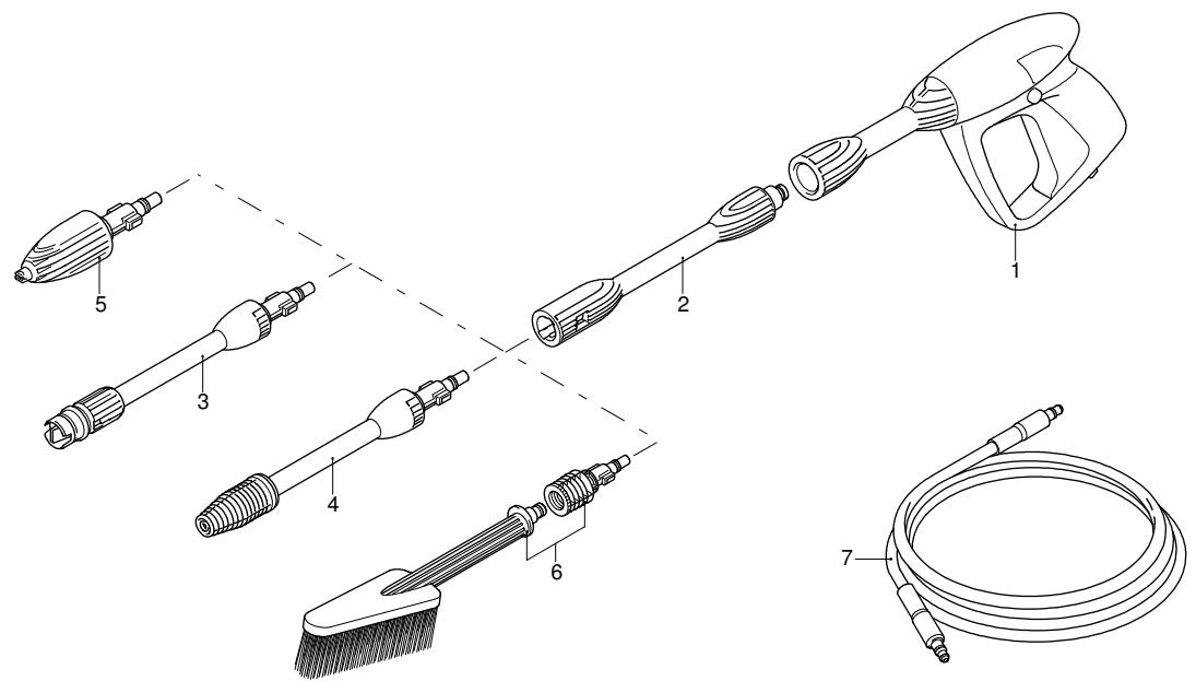
1 3320152 Gun
2 3320130 Extension
3 3640650 | Lance+lance head
4 3320120 Lance+rotopower
5 3640670 | Lance head
6 3640950 Fixed brush
7 3640660 | High pressure hose