USER MANUAL PTS 10 BOSCH
natural_image
3D technical illustration of a Bosch PTS10 machine tool (no text or symbols on the device itself)
Robert Bosch GmbH
Power Tools Division
D-70745 Leinfelden-Echterdingen
Germany
www.bosch-pt.com
1 609 929 T49 (2009.12) PS / 486 UNI

1 609 929 T49
PTS 10

BOSCH
de Originalbetriebsanleitung
en Original instructions
fr Notice originale
es Manual original
pt Manual original
it Istruzioni originali
nl Oorspronkelijke gebruiksaanwijzing
da Original brugsanvisning
sv Bruksanvisning i original
no Original driftsinstruks
fi Alkuperäiset ohjeet
el Πρωτότυπο οδηγιών χρήσης
tr Orijinal işletme talimatı
pl Instrukcja oryginalna
cs Původní návod k používání
sk Pôvodný návod na použitie
hu Eredeti használati utasítás
ru Оригинальное руководство по эксплуатации
uk Оригінальна інструкція з експлуатації
ro Instructiuni originale
bg Оригинална инструкция
sr Originalno uputstvo za rad
sl Izvirna navodila
hr Originalne upute za rad
et Algupärane kasutusjuhend
Iv Instrukcijas oriğinālvalodā
It Originali instrukcija

2 |
natural_image
3D rendered mechanical part with a curved blade and perforated edge, labeled with number 22 (no text or symbols on the object itself)
PTS 10
4 |
natural_image
Exploded view of a Bosch PTS 10 machine with various cutaway views (no text or symbols)
6 |
natural_image
3D mechanical assembly diagram showing internal components with no visible text or symbols
1 609 929 T49 | (19.11.09)
Bosch Power Tools
8 |
10 |
k1-k3 ▶ 15
natural_image
Isometric view of metal structural beams with a Bosch brand logo, no text or symbols present
12 |
F

natural_image
Line drawing of a person using a machine tool, wearing headphones and focused on the work (no text or symbols)
natural_image
Illustration of a hand operating a machine tool with a circular dial, no visible text or symbols
14 |
k1
16 |
natural_image
3D architectural rendering of a metal truss structure with structural beams and mounting holes, showing a close-up inset (no text or symbols)
natural_image
3D rendering of a Bosch PTS 10 machine on a metal stand, showing blade and workpiece components (no text or symbols on the device itself)
Sicherheitshinweise
natural_image
Abstract diagram with curved arrows and shaded regions, no text or symbols present
Bedeutung
natural_image
Circular mechanical component with three curved arrows labeled '6' indicating rotation or clockwise motion (no text or symbols beyond the number)
Bedeutung
Dr. Egbert Schneider
Senior Vice President
Engineering
Dr. Eckerhard Strötgen
Head of Product
Certification

i.v. Mogen
Robert Bosch GmbH, Power Tools Division D-70745 Leinfelden-Echterdingen Leinfelden, 04.07.2008
Montage
WARNING
Read all safety warnings and all instructions. Failure to follow
the warnings and instructions may result in electric shock, fire and/or serious injury.
Save all warnings and instructions for future reference.
The term “power tool” in the warnings refers to your mains-operated (corded) power tool or battery-operated (cordless) power tool.
1) Work area safety
a) Keep work area clean and well lit. Cluttered or dark areas invite accidents.
b) Do not operate power tools in explosive atmospheres, such as in the presence of flammable liquids, gases or dust. Power tools create sparks which may ignite the dust or fumes.
c) Keep children and bystanders away while operating a power tool. Distractions can cause you to lose control.
2) Electrical safety
a) Power tool plugs must match the outlet. Never modify the plug in any way. Do not use any adapter plugs with earthed (grounded) power tools. Unmodified plugs and matching outlets will reduce risk of electric shock.
b) Avoid body contact with earthed or grounded surfaces, such as pipes, radiators, ranges and refrigerators. There is an increased risk of electric shock if your body is earthed or grounded.
c) Do not expose power tools to rain or wet conditions. Water entering a power tool will increase the risk of electric shock.
d) Do not abuse the cord. Never use the cord for carrying, pulling or unplugging the power tool. Keep cord away from heat, oil, sharp edges and moving parts. Damaged or entangled cords increase the risk of electric shock.
e) When operating a power tool outdoors, use an extension cord suitable for outdoor use. Use of a cord suitable for outdoor use reduces the risk of electric shock.
f) If operating a power tool in a damp location is unavoidable, use a residual current device (RCD) protected supply. Use of an RCD reduces the risk of electric shock.
3) Personal safety
a) Stay alert, watch what you are doing and use common sense when operating a power tool. Do not use a power tool while you are tired or under the influence of drugs, alcohol or medication. A moment of inattention while operating power tools may result in serious personal injury.
b) Use personal protective equipment. Always wear eye protection. Protective equipment such as dust mask, non-skid safety shoes, hard hat, or hearing protection used for appropriate conditions will reduce personal injuries.
c) Prevent unintentional starting. Ensure the switch is in the off-position before connecting to power source and/or battery pack, picking up or carrying the tool. Carrying power tools with your finger on the switch or energising power tools that have the switch on invites accidents.
d) Remove any adjusting key or wrench before turning the power tool on. A wrench or a key left attached to a rotating part of the power tool may result in personal injury.
e) Do not overreach. Keep proper footing and balance at all times. This enables better control of the power tool in unexpected situations.
f) Dress properly. Do not wear loose clothing or jewellery. Keep your hair, clothing and gloves away from moving parts.
Loose clothes, jewellery or long hair can be caught in moving parts.
36 | English
g) If devices are provided for the connection of dust extraction and collection facilities, ensure these are connected and properly used. Use of dust collection can reduce dust-related hazards.
a) Do not force the power tool. Use the correct power tool for your application. The correct power tool will do the job better and safer at the rate for which it was designed.
b) Do not use the power tool if the switch does not turn it on and off. Any power tool that cannot be controlled with the switch is dangerous and must be repaired.
c) Disconnect the plug from the power source and/or the battery pack from the power tool before making any adjustments, changing accessories, or storing power tools. Such preventive safety measures reduce the risk of starting the power tool accidentally.
d) Store idle power tools out of the reach of children and do not allow persons unfamiliar with the power tool or these instructions to operate the power tool. Power tools are dangerous in the hands of untrained users.
e) Maintain power tools. Check for misalignment or binding of moving parts, breakage of parts and any other condition that may affect the power tool's operation. If damaged, have the power tool repaired before use. Many accidents are caused by poorly maintained power tools.
f) Keep cutting tools sharp and clean. Properly maintained cutting tools with sharp cutting edges are less likely to bind and are easier to control.
g) Use the power tool, accessories and tool bits etc. in accordance with these instructions, taking into account the working conditions and the work to be performed. Use of the power tool for operations different from those intended could result in a hazardous situation.
5) Service
a) Have your power tool serviced by a qualified repair person using only identical replacement parts. This will ensure that the safety of the power tool is maintained.
Safety Warnings for Table Saws
▶ Never stand on the power tool. Serious injuries can occur when the power tool tips over or when inadvertently coming into contact with the saw blade.
▶ Make sure that the guard operates properly and that it can move freely. Never lock the guard in place when opened.
▶ Keep hands away from the cutting area while the machine is running. Danger of injury when coming in contact with the saw blade.
▶ Never reach behind the saw blade in order to hold the workpiece, remove saw dust/wood chips or for any other reason. The clearance of your hand to the rotating saw blade is too small.
▶ Guide the workpiece against the saw blade only when the machine is switched on. Otherwise there is damage of kickback, when the saw blade becomes wedged in the workpiece.
▶ Operate the power tool only when the work area to the workpiece is clear of any adjusting tools, wood chips, etc. Small pieces of wood or other objects that come in contact with the rotating saw blade can strike the operator with high speed.
▶ Only saw one workpiece at a time. Workpieces placed on top or aside of each other can cause the saw blade to jam or the workpieces to move against each other while sawing.
▶ Always use the parallel guide or the angle guide. This improves the cutting accuracy and reduces the possibility of saw blade binding.
English
If the saw blade should become jammed, switch the machine off and hold the workpiece until the saw blade comes to a complete stop. To prevent kickback, the workpiece may not be moved until after the machine has come to a complete stop. Correct the cause for the jamming of the saw blade before restarting the machine.
▶ Do not use dull, cracked, bent or damaged saw blades. Unsharpened or improperly set saw blades produce narrow kerf causing excessive friction, blade binding and kickback.
▶ Always use saw blades with correct size and shape (diamond versus round) of arbor holes. Saw blades that do not match the mounting hardware of the saw will run eccentrically, causing loss of control.
▶ Do not use high speed steel (HSS) saw blades. Such saw blades can easily break.
▶ Do not touch the saw blade after working before it has cooled. The saw blade becomes very hot while working.
▶ Never operate the machine without the insert plate. Replace a defective insert plate. Without flawless insert plates, injuries are possible from the saw blade.
- Secure the workpiece. A workpiece clamped with clamping devices or in a vice is held more secure than by hand.
▶ Keep your workplace clean. Blends of materials are particularly dangerous. Dust from light alloys can burn or explode.
▶ Never leave the machine before it has come to a complete stop. Cutting tools that are still running can cause injuries.
▶ Never use the machine with a damaged cable. Do not touch the damaged cable and pull the mains plug when the cable is damaged while working. Damaged cables increase the risk of an electric shock.
Products sold in GB only: Your product is fitted with an BS 1363/A approved electric plug with internal fuse (ASTA approved to BS 1362).
If the plug is not suitable for your socket outlets, it should be cut off and an appropriate plug fitted in its place by an authorised customer service agent. The replacement plug should have the same fuse rating as the original plug.
The severed plug must be disposed of to avoid a possible shock hazard and should never be inserted into a mains socket elsewhere.
Symbols
The following symbols can be important for the operation of your power tool. Please memorise the symbols and their meanings. The correct interpretation of the symbols helps you operate the power tool better and more secure.
| Symbol | Meaning |
 | ► Wear ear protectors. Exposure to noise can cause hearing loss. |
 | ► Wear a dust respirator. |
38 | English
| Symbol | Meaning |
 | ► Wear safety goggles. |
 | ► Danger area! Keep hands, fingers or arms away from this area. |
 | Only for EC countries:Do not dispose of power tools into household waste!According the European Guideline 2002/96/EC for Waste Electrical and Electronic Equipment and its implementation into national right, power tools that are no longer usable must be collected separately and disposed of in an environmentally correct manner. |
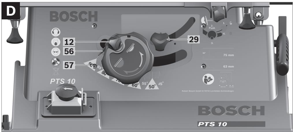
 | Indicates the rotation direction of the handwheel for lowering (transport position) and raising (working position) the saw blade. |
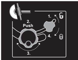 | Carry out the adjustment of the bevel angle (= vertical mitre angle) (saw blade can be tilted) in the indicated sequence. |
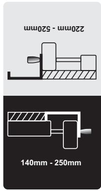
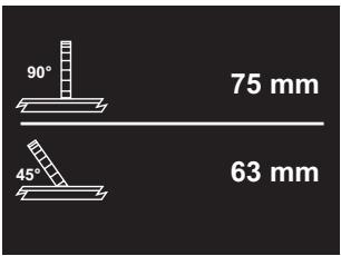 | Indicates the maximum permissible workpiece height for the standard bevel angles 90° and 45°. |
English
Symbol
Meaning
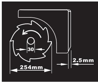
Observe the dimensions of the saw blade. The hole diameter must match the tool spindle without play. Do not use reducers or adapters.
When changing the saw blade, pay attention that the cutting width is not smaller and the blade thickness is not larger than the thickness of the riving knife.

natural_image
Circular mechanical component with three curved arrows labeled '6' indicating rotation or adjustment (no text or symbols beyond the number)
Indicates the function of the locking knob on the angle stop when adjusting mitre angles.
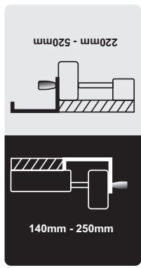
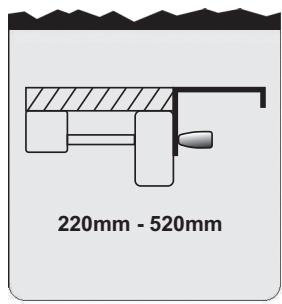
Indicates the possible positions of the parallel fence at the table width enlargement.
The colour of the sticker corresponds with the scale colours on the front guide rod. Depending on the position of the parallel fence, the scale indicates the clearance to the saw blade.
Functional Description

Read all safety warnings and all instructions. Failure to follow the warnings and instructions may result in electric shock, fire and/or serious injury.
Intended Use
The power tool is intended as a stationary machine for making straight lengthways and crossways cuts in wood. Horizontal mitre angles of -60^ to +60^ as well as vertical bevel angles of 90^ to 45^ are possible.
The machine is designed with sufficient capacity for sawing hard and softwood as well as press and particle board.
When operating as a table saw, the power tool is not permitted for cutting aluminium or other non-ferrous metals or alloys.
40 | English
Product Features
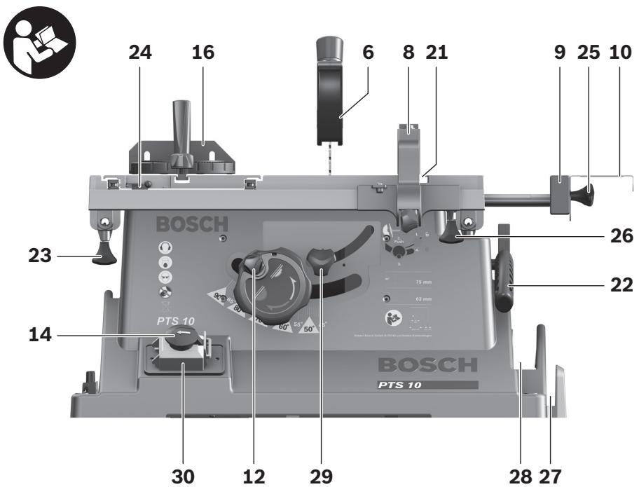
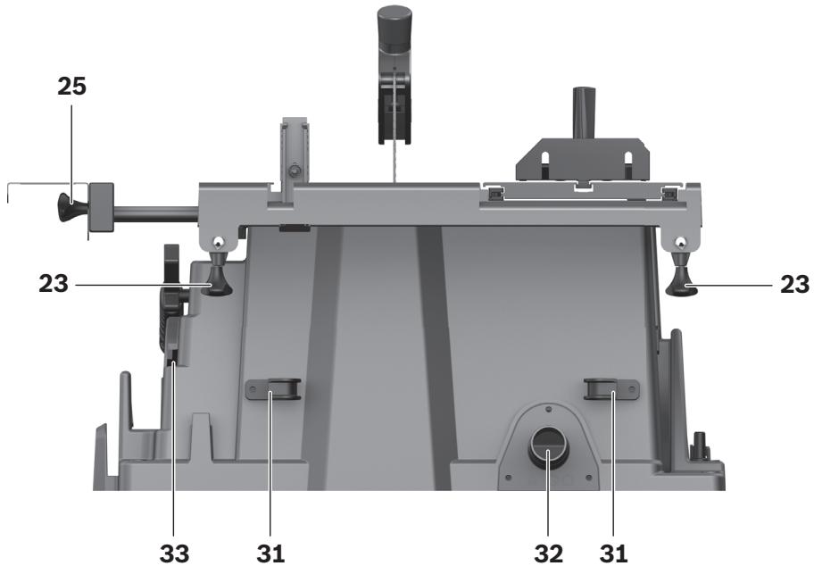
The numbering of the components shown refers to the representation of the power tool on the graphic pages.
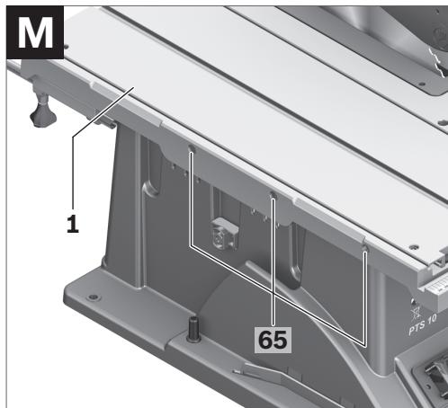
1 Sliding table
2 Table extension
3 Insert plate
4 Riving knife
5 Vacuum connection on the blade guard
6 Blade guard
7 Sticker for marking of the cutting line
8 Parallel guide
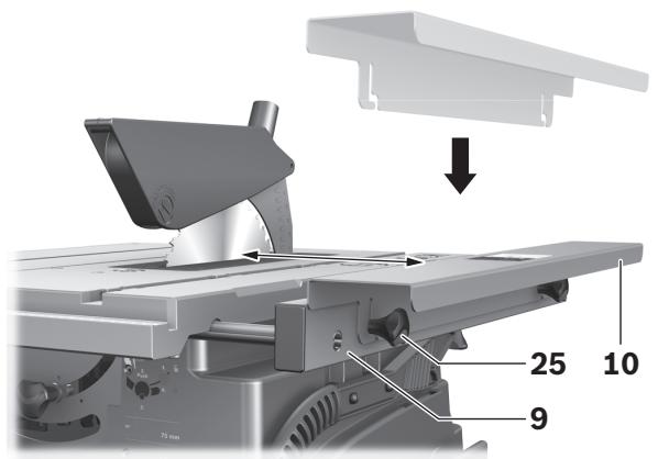
9 Table width enlargement
10 Parallel fence of the table width enlargement 9
11 Saw table
12 Handwheel for lowering and raising the saw blade
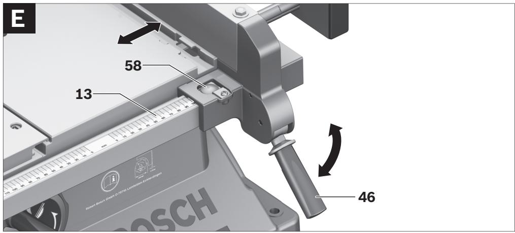
13 Scale for clearance of the saw blade to the parallel guide 8
14 EMERGENCY OFF button
15 Guide groove for parallel guide 8
16 Angle stop
17 Ring spanner (23 mm; 13 mm)
18 Auxiliary parallel fence (aluminium)
19 Fastening screw of saw-blade storage
20 Mounting holes
21 Guide groove for angle stop
22 Hold-down stick
23 Fastening knob for table extension 2
24 Locking lever of the sliding table
25 Fastening knob for parallel fence 10
26 Fastening knob for table width enlargement 9
27 Storage for auxiliary parallel fence 18
28 Storage for parallel guide 8
29 Locking knob for adjustment of bevel angles
30 Safety flap of On/Off switch
31 Cable holder
32 Sawdust ejector
33 Storage for angle stop
34 Vacuum hose
35 Bottom plate
36 Hexagon bolt for fastening of the riving knife 4
37 Insert-plate notches
38 Saw blade
39 Fixture for riving knife
40 Fastening kit for "blade guard"
41 Fastening kit for "table extension"
42 Rubber buffer
43 Guide rail of the angle stop
44 Locking knob on the angle guide
45 Fastening kit for "auxiliary parallel fence/angle stop"
46 Clamping knob of the parallel guide
47 Profile rail
48 Fastening knobs for auxiliary parallel fence (aluminium)
49 Auxiliary parallel fence (plastic)
50 Spindle lock lever
51 Clamping nut
52 Supporting/clamping flange
53 Tool spindle
54 Locking knob for bevel angle (horizontal)
55 Angle indicator on the angle guide
56 Angle indicator (vertical)
57 Scale for bevel angle (vertical)
58 Lens
59 Scale for clearance of the saw blade to the parallel fence 10
60 ON pushbutton
61 Adjusting screw for setting the standard 90° bevel angle
62 Adjusting screw for setting the standard 45° bevel angle
63 Screw for angle indicator (vertical)
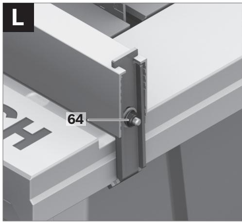
64 Nut for adjustment of the parallel-fence tensioning force 8
65 Adjusting screws for sliding-table play
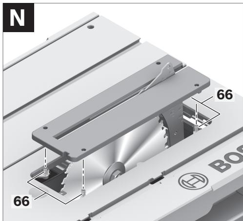
66 Adjusting screws for insert plate
67 Recessed grips
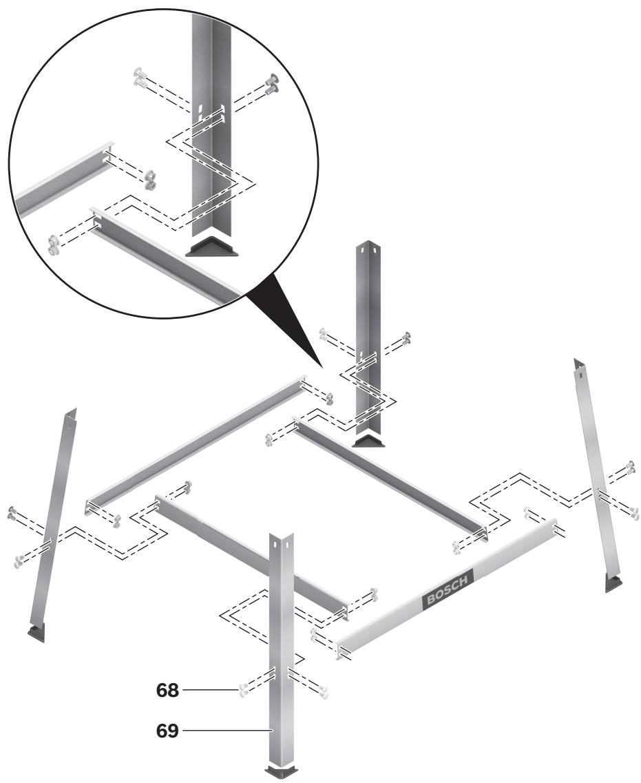
68 Fastening kit for "base unit"*
69 Base unit*
*Accessories shown or described are not part of the standard delivery scope of the product. A complete overview of accessories can be found in our accessories program.


Technical Data
| Table saw | PTS 10 |
| Article number | | 3 603 L03 2.. |
| Rated power input | W | 1400 |
| Rated voltage | V | 230 |
| Frequency | Hz | 50 |
| No-load speed | min^-1 | 5000 |
| Reduced starting current | | ● |
| Weight according to EPTA-Procedure 01/2003 | kg | 23.5 |
| Protection class | | /II |
Maximum workpiece dimensions, see page 48.
The values given are valid for nominal voltages [U] of 230/240 V. For lower voltage and models for specific countries, these values can vary.
Please observe the article number on the type plate of your machine. The trade names of the individual machines may vary.
Dimension of suitable saw blades
| Saw blade diameter | mm | 254 |
| Blade thickness | mm | 1.8 |
| Mounting hole diameter | mm | 30 |
Measured sound values determined according to EN 61029.
Typically the A-weighted noise levels of the product are: Sound pressure level 97 dB(A); Sound power level 110 dB(A). Uncertainty K=3 dB.
Wear hearing protection!
We declare under our sole responsibility that the product described under “Technical Data” is in conformity with the following standards or standardization documents: EN 61029 according to the provisions of the directives 2004/108/EC, 98/37/EC (until 28 Dec 2009), 2006/42/EC (from 29 Dec 2009).
EC Type Certification No. 3400636.01CE by notified testing agency No. 2140.
Technical file at:
Robert Bosch GmbH, Dept. PT/ESC,
D-70745 Leinfelden-Echterdingen
Dr. Egbert Schneider
Senior Vice President
Engineering
Dr. Eckerhard Strötgen
Head of Product
Certification
ppa. Macau i.v. Nuoyen
Robert Bosch GmbH, Power Tools Division D-70745 Leinfelden-Echterdingen Leinfelden, 04.07.2008
Assembly
▶ Avoid unintentional starting of the machine. During assembly and for all work on the machine, the power plug must not be connected to the mains supply.
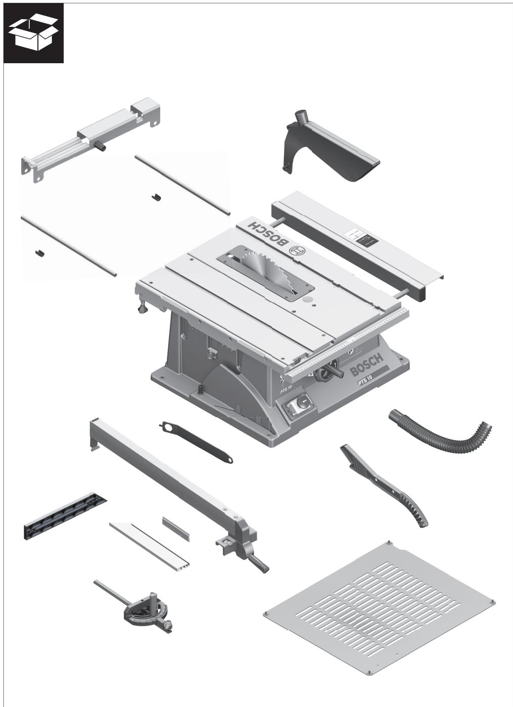
Delivery Scope

Please also observe the representation of the delivery scope at the beginning of the operating instructions.
Before starting the operation of the machine for the first time, check if all parts listed below have been supplied:
- Table saw
(Preassembled: Table width enlargement 9, saw blade 38, insert plate 3)
- Bottom plate 35 with pre-mounted Phillips screws
- Table extension 2
42 | English
- Fastening kit for “table extension” 41 (2 guide rods, 2 securing screws, 2 clips, 2 short fastening knobs)
- Parallel fences 8 and 10
- Auxiliary parallel fence (aluminium) 18 with profile rail 47
– Auxiliary parallel fence (plastic) 49
- Angle stop 16
- Fastening kit for “auxiliary parallel guide” 45 (4 short screws, 2 long fastening knobs 48, 2 square nuts and washers)
- Blade guard 6
- Fastening kit for "blade guard" 40 (screw, nut, washer)
- Riving knife 4 with pre-mounted hexagon bolt 36
- Vacuum hose 34
- Hold-down stick 22
- Ring spanner 17
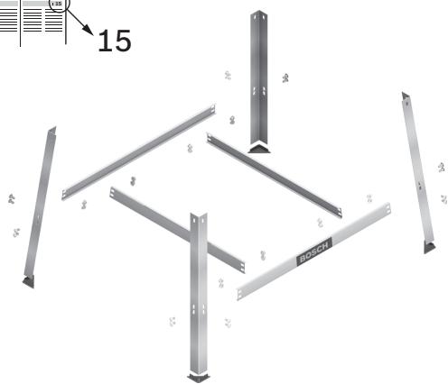
for machine versions with base unit:
- Base unit 69
(12 Profiles, 4 end caps)
- Fastening kit for base unit 68
(24 screws with nuts for assembly, 4 screws with nuts for fastening of the machine, 4 washers)
Note: Check the power tool for possible damage.
Before further use of the machine, check that all protective devices are fully functional. Any lightly damaged parts must be carefully checked to ensure flawless operation of the tool. All parts must be properly mounted and all conditions fulfilled that ensure faultless operation.
Damaged protective devices and parts must be immediately replaced by an authorised service centre.
Initial Operation
- Carefully remove all parts included in the delivery from their packaging.
- Remove all packaging material from the machine and the accessories provided.
- Take special care to ensure that the packaging material under the motor block is removed.
- Phillips screwdriver
- Angle gauge
- Box-end or open-end spanner (size 13 mm) for assembly of the base unit
Assembly Sequence
For easier working, observe the assembly sequence of the supplied product features.
1. Assembly from Below
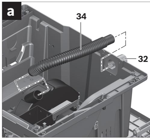
- Vacuum hose 34
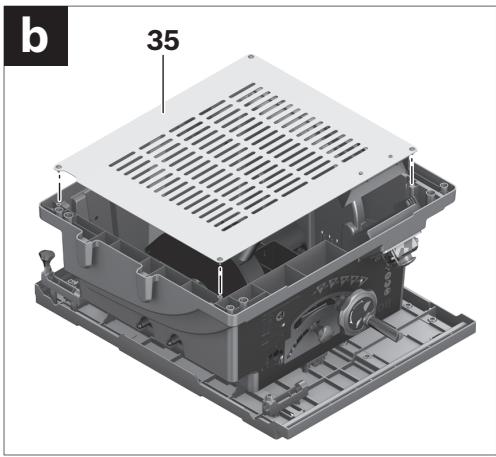
- Bottom plate 35 with pre-mounted Phillips screws
2. Assembly from Above
- Riving knife 4
- Blade guard 6
- Table extension 2
- Parallel fence 8, auxiliary parallel fences (18 or 49) and angle stop 16
Assembly from Below
- Place down the power tool upside down on its saw table 11.
- Connect the sawdust ejector on the saw blade casing and the sawdust ejector 32 on the machine housing with the vacuum hose 34.
- Insert the bottom plate 35 into the intended recesses so that the Phillips screws can be screwed into the holes of the housing.
- Fasten the bottom plate by screwing in and tightening the Phillips screws.
Assembly from Above
- Turn the power tool around so that it is in the correct working position.
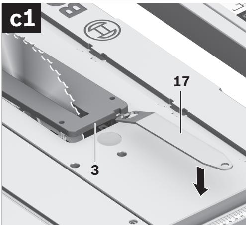
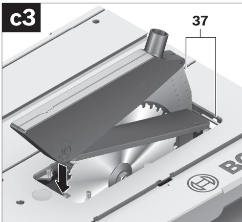
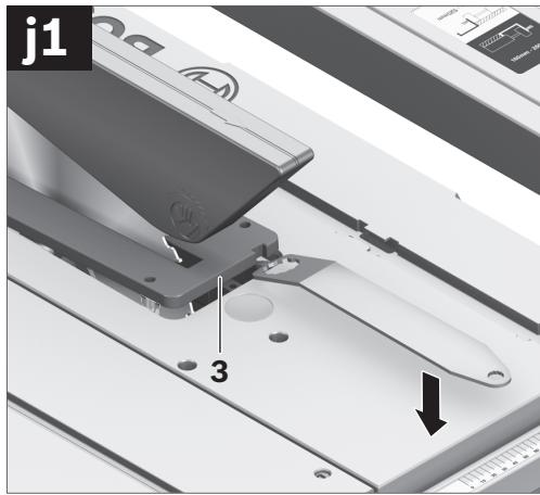
- Using the ring spanner 17, lift up the insert plate 3 at the front and remove it from the notches 37.
- Turn handwheel 12 in anticlockwise direction to the stop so that the saw blade 38 is in the highest possible position above the saw table.
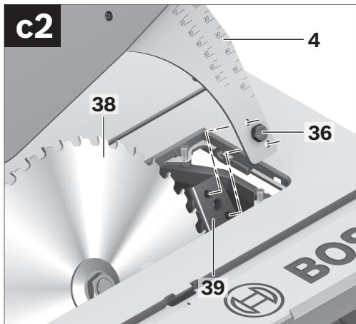
- Loosen locking knob 29 to tilt the saw blade 38.
- Insert the riving knife 4 so that the respective holes are positioned on the guide bolts of the riving knife fixture 39.
- Fasten the riving knife 4 to fixture 39 by firmly tightening hexagon bolt 36 with ring spanner 17 (13 mm).
- Readjust the saw blade back to 90° again and tighten locking knob 29. (also see “Adjusting Vertical Bevel Angles”, page 46)
Note: The riving knife must be in alignment with the saw blade to avoid jamming of the workpiece.
- Finally, reassemble the insert plate 3. For this, hook the insert plate into the notches 37 and then press the insert plate downward until it engages in the saw table.
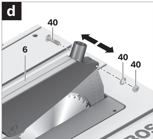
For assembly, use the fastening kit for “blade guard” 40. (screw, nut, washer)
- Insert screw 40 through the holes of the blade guard and riving knife.
The square head of the screw must engage in the corresponding recess of the blade guard.
- Mount the washer and the nut.
- Tighten the nut sufficiently with the ring spanner 17 (13 mm) so that the blade guard remains secured in any set position.
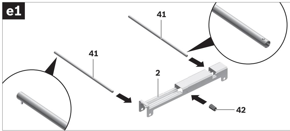
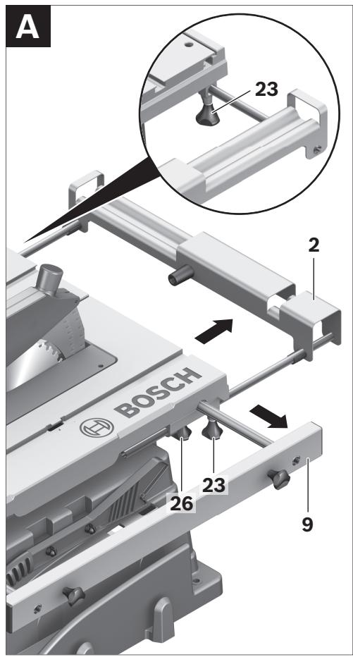
For assembly, use the fastening kit for “table extension” 41. (2 guide rods, 2 securing screws, 2 clips, 2 short fastening knobs)
- Insert both guide rods (rod end with threaded hole ahead) to the stop into the appropriate holes on the table extension 2.
- Screw the rubber buffer 42 onto the table extension.
- Fasten the guide rods to the extension bar by inserting the clips into the threaded holes.
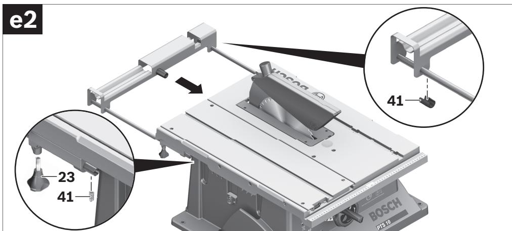
- Afterwards, insert the table extension via both guide rods into the intended fixtures under the saw table.
- Screw the securing screws against pulling out, into the threads intended for this purpose.
- Screw the fastening knobs 23 into the threads intended for this purpose under the saw table.
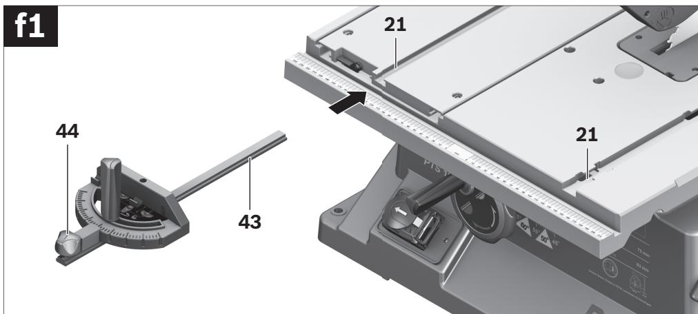
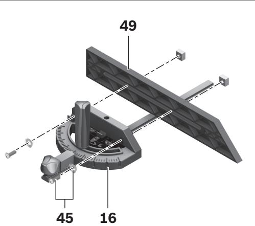
- Insert the guide rail 43 of the angle stop 16 into one of the guide grooves 21 of the saw table intended for this purpose.
Note: In the lefthand guide groove, the position of the angle stop can be affixed on the sliding table by screwing in the locking knob 44.
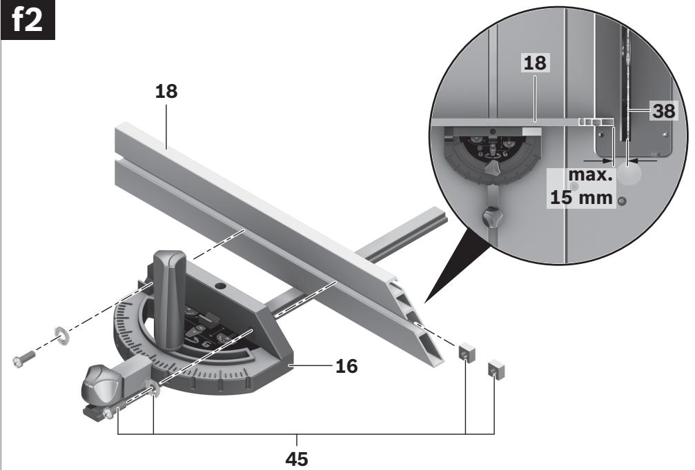
- Mount the aluminium auxiliary parallel fence 18 to the angle stop with the supplied fastening kit 45. (2 short screws, 2 square nuts and washers)
Note: Take care that the auxiliary parallel fence rests completely on saw table.
The clearance between saw blade and auxiliary parallel fence may not exceed 15 mm (max.).
44 | English
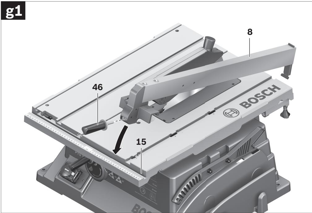
The parallel guide 8 can be positioned either left or right from the saw blade.
- Screw the clamping knob 46 into the thread intended for this purpose at the front of the parallel fence.
- Firstly, place the parallel fence onto the rear of the saw table. Now, position the parallel fence in guide groove 15.
The parallel fence can now be moved to any position.
- To lock the parallel guide, press the clamping knob 46 down.
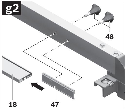
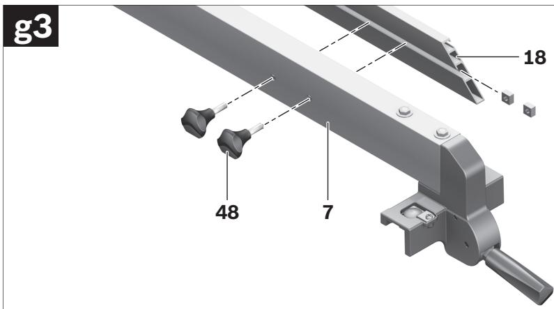
When sawing narrow workpieces and for bevel cuts, the auxiliary parallel fence (aluminium) 18 must be mounted to parallel fence 8.
In this case, the auxiliary parallel fence (plastic) 49 can be mounted to the angle stop.
- Insert the profile rail 47 into the groove on the short side of the auxiliary parallel fence 18.
- Position the profile rail 8 in front of the parallel fence in such a manner that the holes of both parts are in alignment.
- Insert the fastening knobs 48 through the lateral holes in the parallel fence and tighten them.
When sawing high, narrow workpieces, the auxiliary parallel fence (aluminium) 18 must be mounted directly to parallel fence 8.
- Fasten the auxiliary parallel fence 18 with the 2 square nuts from fastening kit 45 and the fastening knobs 48 directly to the parallel fence 8.
Dusts from materials such as lead-containing coatings, some wood types, minerals and metal can be harmful to one's health. Touching or breathing-in the dusts can cause allergic reactions and/or lead to respiratory infections of the user or bystanders.
Certain dusts, such as oak or beech dust, are considered as carcinogenic, especially in connection with wood-treatment additives (chromate, wood preservative). Materials containing asbestos may only be worked by specialists.
- Use dust extraction whenever possible.
- Provide for good ventilation of the working place.
- It is recommended to wear a P2 filter-class respirator.
Observe the relevant regulations in your country for the materials to be worked.
The dust/chip extraction can be blocked by dust, chips or workpiece fragments.
- Switch the machine off and pull the mains plug from the socket outlet.
- Wait until the saw blade has come to a complete stop.
- Determine the cause of the blockage and correct it.
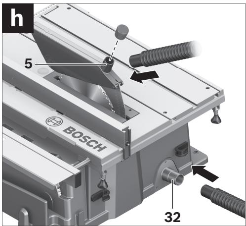
- Connect a vacuum hose to the sawdust ejector 32.
- Additionally, a dust extraction system can be connected to vacuum connection 5 to increase the extraction performance.
For this, remove the cap from the vacuum connection.
The vacuum cleaner must be suitable for the material being worked.
When vacuuming dry dust that is especially detrimental to health or carcinogenic, use a special vacuum cleaner.
Stationary or Flexible Mounting
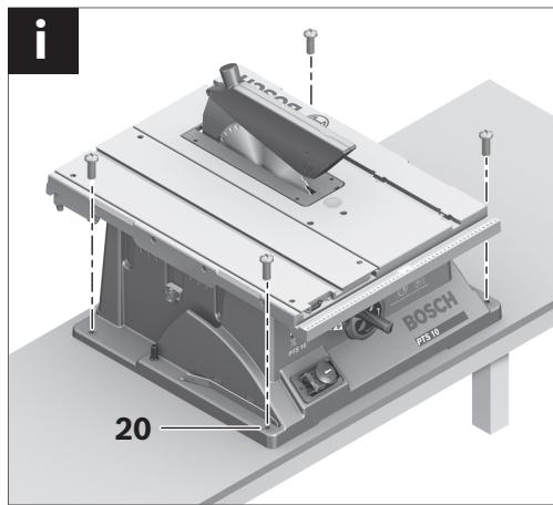
▶ To ensure safe handling, the machine must be mounted on a level and stable surface (e.g., workbench) prior to using.
- Fasten the power tool with suitable screw fasteners to the working surface. The holes 20 serve for this purpose.
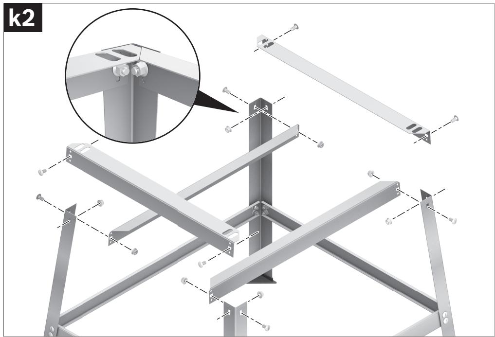
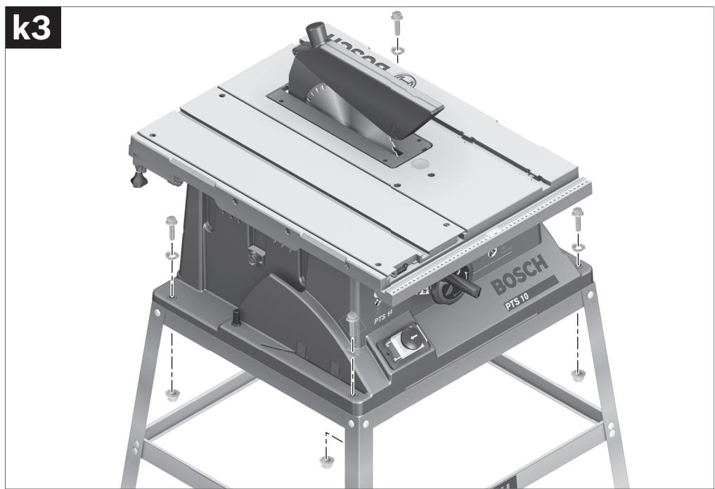
Mounting with Base Unit (see figures k1-k3 from page 15 on)
For mounting, use the base-unit fastening kit 68. (24 screws with nuts for assembly, 4 screws with nuts for fastening of the machine, 4 washers)
- Screw the base unit 69 together. Tighten the screws firmly.
- Fasten the power tool to the supporting surface of the base unit. For this, use the mounting holes 20 of the power tool as well as the slots in the base unit.
▶ Before any work on the machine itself, pull the mains plug.
- When mounting the saw blade, wear protective gloves. Danger of injury when touching the saw blade.
Select the suitable saw blade for the material to be cut.
Use only saw blades whose maximum permitted speed is higher than the no-load speed of the power tool.
Use only saw blades that correspond with the characteristic data given in these operation instructions and that are tested and marked in accordance with EN 847-1.
Removing the Saw Blade
- Using the ring spanner 17, lift up the insert plate 3 at the front and remove it from the notches 37.
- Turn handwheel 12 in anticlockwise direction to the stop so that the saw blade 38 is in the highest possible position above the saw table.
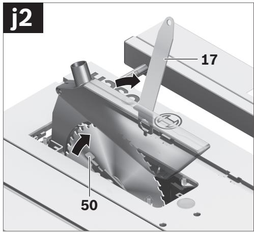
- Turn the clamping nut 51 with the ring spanner 17 (23 mm) and at the same time, pull the spindle lock lever 50 until it engages.
- Keep the spindle lock lever pulled and unscrew the clamping nut turning in anticlockwise direction.
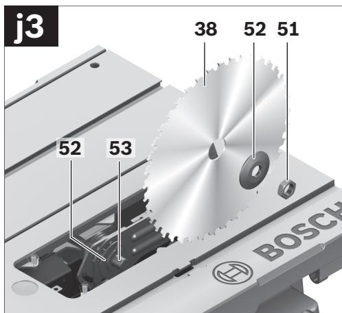
- Remove the clamping flange 52.
- Remove the saw blade 38.
Mounting the Saw Blade
If required, clean all parts to be mounted prior to assembly.
- Place the new saw blade onto the supporting flange 52 of the tool spindle 53.
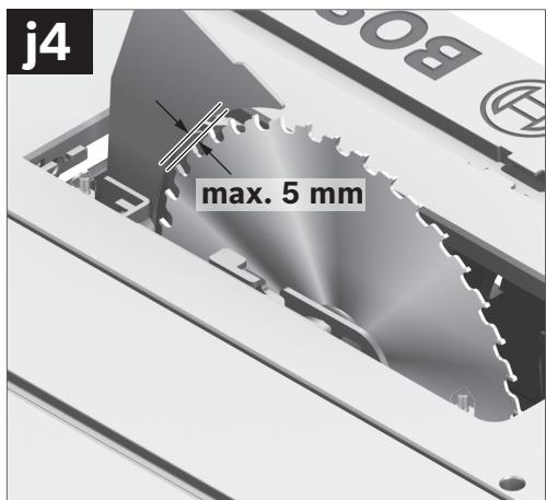
Note: Do not use saw blades that are too small. The clearance between saw blade and riving knife must not exceed 5 mm (max.).
When mounting the saw blade, pay attention that the cutting direction of the teeth (arrow direction on the saw blade) corresponds with the direction of the arrow on the blade guard!
- Mount the clamping flange 52 and the clamping nut 51.
- Turn the clamping nut 51 with the ring spanner 17 (23 mm) and at the same time, pull the spindle lock lever 50 until it engages.
- Tighten the clamping nut in clockwise direction.
- Reinsert the insert plate 3. (see figure c3)
46 | English
Operation
▶ Before any work on the machine itself, pull the mains plug.
Transport and Working Position of the Saw Blade
Transport Position
- Turn the handwheel 12 in clockwise direction until the teeth of the saw blade 38 are positioned below the saw table 11.
Working Position
- Turn the handwheel 12 in anticlockwise direction until the teeth of the saw blade 38 are positioned approx. 5mm above the workpiece.
Note: Take care that the blade guard is properly positioned. When sawing, it must always face against the workpiece.
Increasing the Size of the Saw Table
Long workpieces must be underlaid or supported at their free end.
To increase the saw table surface, the following rails can be pulled out at the rear as well as on the right-hand side of the power tool:
Table extension 2 (extends the saw table 11 toward the rear by 215 mm)
and/or
Table width enlargement 9 (enlarges the saw table 11 toward the right by 285 mm)
- Grasp the requested rail centrally and from below, and pull it out maximally to the stop.
- To lock in position, tighten the corresponding fastening knobs (23 or 26) against the guide rods.
For heavy workpieces, it may be required to support the rails.
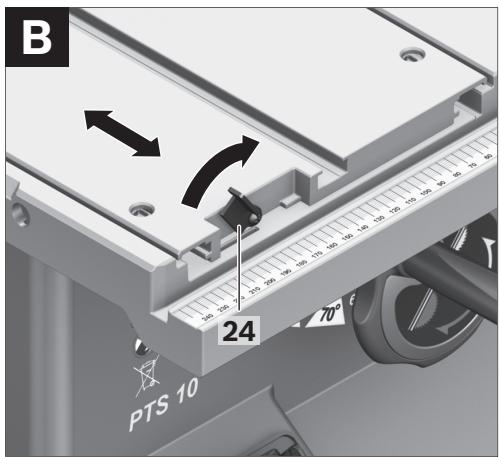
With the sliding table 1, workpieces to a maximum width of 305 mm can be sawn.
At the same time, a higher precision is achieved during sawing, especially in conjunction with the angle stop 16. (see “Sawing Mitre Angles with the Sliding Table”, page 49)
- For this, tilt the locking lever 24 toward the right.
In this manner, the sliding table can be moved both toward the front as well as toward the rear to the stop.
Adjusting the Cutting Angle
To ensure precise cuts, the basic adjustment of the machine must be checked and adjusted as necessary after intensive use (see “Checking and Adjusting the Basic Adjustment”, page 49).
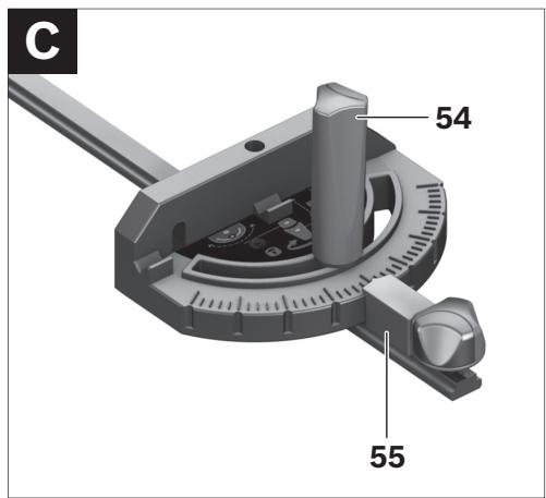
The horizontal mitre angle can be set in the range from 60^ (left side) to 60^ (right side).
- Loosen the locking knob 54 in case it is tightened.
- Turn the angle stop until the angle indicator 55 indicates the requested mitre angle.
- Tighten the locking knob 54 again.
The vertical bevel angle can be set in the range from 90^ to 45^ .
- Lightly unscrew the locking knob 29 in anticlockwise direction.
Note: By completely loosening the locking knob, the saw blade tilts approx. to the 30^ position by means of gravity force.
- Press the handwheel 12 toward the rear (Push) and hold it in this position. This forces the teeth on the connecting link to engage in the gear ring of the handwheel.
- Turn the handwheel until the angle indicator 56 indicates the requested bevel angle on the scale 57.
- Tighten the locking knob 29 again.
For quick and precise setting of the standard angles 90^ and 45^ , end stops are given at the housing.
Adjusting the Parallel Fences
The mark in the lens 58 indicates the set clearance of the parallel fence to the saw blade on the scale 13.
- Position the parallel fence on the requested side of the saw blade. (also see “Mounting the Parallel Guide”, page 44)
- Pull the clamping knob 46 upward to release the lock and move the parallel fence until the lens 58 indicates the requested clearance to the saw blade.
- To lock the parallel guide, press the clamping knob 46 down.
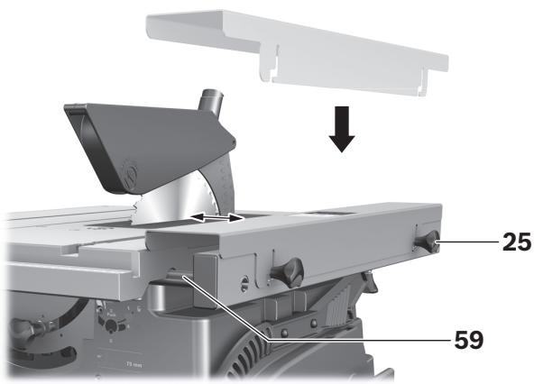
The parallel fence 10 can be positioned either left or right from the table width enlargement 9.
The colour of the sticker on the parallel fence corresponds with the colours of the scale 59 on the front guide rod. Depending on the position of the parallel fence, the scale indicates the clearance to the saw blade.
- Screw the parallel fence at the requested position to the table width enlargement.
- Grasp the table width enlargement centrally and from below, and pull it out until the green or yellow scale indicates the requested clearance to the saw blade.
Adjusting the Auxiliary Parallel Guide
When sawing narrow workpieces and for bevel cuts, the auxiliary parallel fence (aluminium) 18 must be mounted to parallel fence 8. (see figure g2)
When sawing short workpieces, these can become jammed between the parallel guide and the saw blade, be caught by the rotating saw blade, and be thrown from the machine.
Therefore, adjust the auxiliary parallel guide in such a manner that its guiding end is located between the front saw blade tooth and the saw blade centre.
- For this, loosen fastening knobs 48 and move the auxiliary parallel fence 18 accordingly.
- Tighten the fastening knobs again.
When sawing high, narrow workpieces, the auxiliary parallel fence (aluminium) 18 must be mounted directly to parallel fence 8.
(see figure g3)
Starting Operation
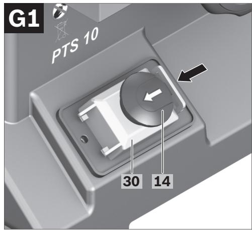
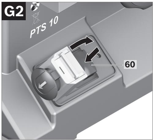
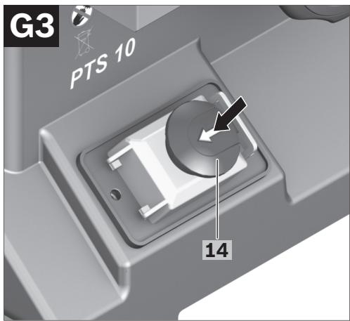
- Push the red EMERGENCY OFF button 14 leftward and open the yellow safety flap 30.
- To start the operation, press the green ON pushbutton 60.
- Afterwards, shut the safety flap without engaging it.
- Press the red EMERGENCY OFF button 14.
Power Failure
The ON/OFF switch is a so-called non-voltage switch, which prevents the power tool from re-starting after a power failure (e. g., when the mains plug is pulled during operation).
To restart the operation of the machine afterwards, the green ON pushbutton 60 must be pressed again.
48 | English
Working Advice
General Sawing Instructions
For all cuts, it must first be ensured that the saw blade at no time can come in contact with the stops or other machine parts.
Protect the saw blade against impact and shock. Do not subject the saw blade to lateral pressure.
The riving knife must be in alignment with the saw blade to avoid jamming of the workpiece.
Do not saw warped/bent workpieces. The workpiece must always have a straight edge to face against the parallel guide.
Always keep/store the hold-down stick with the power tool.
Do not use the power tool for joining, grooving or cutting slots.
Marking the Cutting Line
- Mark the saw blade width on the round yellow sticker 7.
This allows for exact positioning of the workpiece for sawing, without having to open the blade guard.
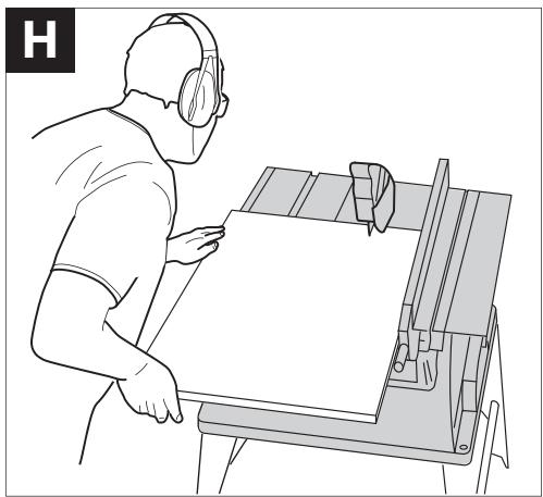
▶ Do not stand in a line with the saw blade in front of the machine. Always stand aside of the saw blade. This protects your body against possible kickback.
- Keep hands, fingers and arms away from the rotating saw blade.
Observe the following instructions:
- Hold the workpiece securely with both hands and press it firmly against the saw table, especially when working without the guide. (see figure 1)
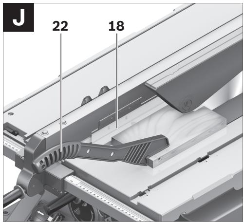
- When sawing narrow workpieces and bevel angles, always use the supplied hold-down stick 22 and the auxiliary parallel guide 18. (see figure J)
Maximum Workpiece Dimensions
| Vertical bevel angle | Max. workpiece height [mm] |
| 90° | 75 |
| 45° | 63 |
Sawing
Sawing Straight Cuts
- Adjust the parallel guide 8 to the requested cutting width (see “Adjusting the Parallel Fences”, page 47)
- Position the workpiece on the saw table in front of the protection guard 6.
- Raise or lower the saw blade with the handwheel 12 so that the upper saw teeth project approx. 5 mm above the workpiece surface.
Note: Take care that the blade guard is properly positioned. When sawing, it must always face against the workpiece.
- Switch on the machine.
- Saw through the workpiece applying uniform feed.
- Switch off the machine and wait until the saw blade has come to a complete stop.
Sawing Bevel Angles
- Adjust the requested bevel angle. (see "Adjusting Vertical Bevel Angles", page 46)
- Follow the worksteps in section “Sawing Straight Cuts” accordingly.
The clearance between saw blade and auxiliary parallel fence may not exceed 15 mm (max.).
- When the auxiliary parallel fence 18 is behind the cutting line, loosen both screws of fastening kit 45.
- Move the auxiliary parallel fence and tighten the screws again.
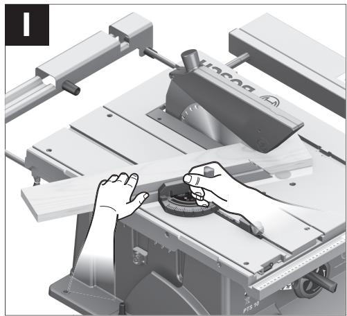
Sawing Mitre Angles with the Sliding Table Locked
- Adjust the requested horizontal mitre angle (see “Adjusting Horizontal Mitre Angles”, page 46)
- The angle stop must move freely in the guide groove 21 (leftward or rightward). For this, loosen locking knob 44, if required.
- Follow the worksteps in section “Sawing Straight Cuts” accordingly.
Sawing Mitre Angles with the Sliding Table
- Adjust the requested horizontal mitre angle (see “Adjusting Horizontal Mitre Angles”, page 46)
- Tilt the locking lever 24 toward the right and push the sliding table 1 toward the front. (see figure B)
- Position the workpiece on the saw table in front of the protection guard 6.
- Position the angle stop 16 in front of the workpiece in the lefthand guide groove 21. Lock this position by firmly tightening locking knob 44.
- Follow the worksteps in section “Sawing Straight Cuts” accordingly.
Checking and Adjusting the Basic Adjustment
To ensure precise cuts, the basic adjustment of the machine must be checked and adjusted as necessary after intensive use.
A certain level of experience and appropriate specialty tools are required for this.
A Bosch after-sales service station will handle this maintenance task quickly and reliably.
Setting the Standard Bevel Angle 90° (Vertical)
- Adjust a 90° bevel angle.
Checking:
- Set an angle gauge to 90^ and place it on the saw table 11.
The leg of the angle gauge must be flush with the saw blade 38 over the complete length.
- Loosen the locking knob 29 and hold the saw blade with help of the handwheel 12 in the 90^ position.
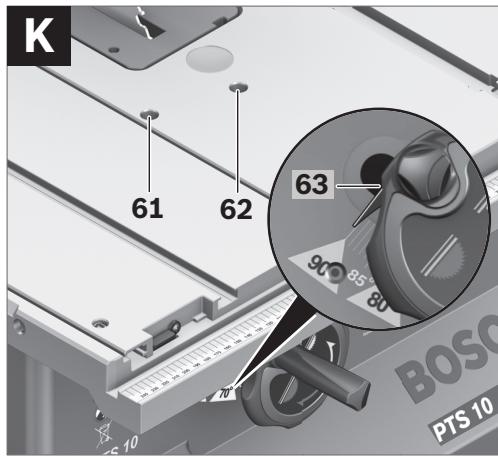
- Loosen adjusting screw 61 and lightly retighten the locking knob 29.
- Screw the adjusting screw in or out until the leg of the angle gauge is flush with the saw blade over the complete length.
- Afterwards, firmly tighten the locking knob 29 again.
When the angle indicator 56 is not in line with the 90° mark of scale 57, loosen screw 63 with a commercially available Phillips screwdriver and align the angle indicator alongside the 90° mark.
- Repeat the above mentioned worksteps accordingly for the 45° bevel angle: Loosen locking knob 29, adjust the adjusting screw 62.
In this, the angle indicator 56 must not be readjusted.
The tensioning force of the parallel fence 8 can decrease after frequent usage.
- Tighten nut 64 until the parallel fence can be firmly locked to the saw table again.
- When the play of the sliding table 1 becomes too large after frequent usage, tighten the adjusting screws 65.
50 | English
Checking:
The front side of the insert plate 3 must be flush with or somewhat lower than the saw table; the rear side must be flush with or somewhat above the saw table.
Adjusting:
- Adjust the correct level with help of the four adjusting screws 66.
For storage purposes, the hold-down stick, stops/guides and spare saw blades can be securely fastened to the power tool.
- Lock the yellow safety flap 30 and the locking lever 24 of the sliding table 1.
- Bring the machine into the transport position. (see “Transport Position”, page 46)
- Loosen the auxiliary parallel fence 18 from the parallel fence 8 or from the angle stop 16.
- Position the stops/fences (8, 16, 18) and fasten the hold-down stick 22.
- Wind the mains cable around the cable holder 31.
- A spare saw blade can be fastened to the machine housing for storage with help of the fastening screw 19.
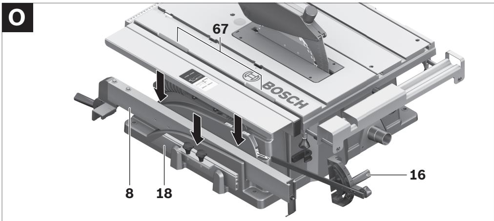
▶ The power tool should always be carried by two persons in order to avoid back injuries.
▶ When transporting the power tool, only use the transport fixtures. Never carry the power tool by the protective devices, the table extension 2 or the table width enlargement 9.
- For lifting or transporting, hold the power tool by the recessed grips 67 on the side of the saw table 11.
Maintenance and Service
Maintenance and Cleaning
▶ Before any work on the machine itself, pull the mains plug.
If the machine should fail despite the care taken in manufacturing and testing procedures, repair should be carried out by an after-sales service centre for Bosch power tools.
In all correspondence and spare parts order, please always include the 10-digit article number given on the type plate of the machine.
Cleaning
For safe and proper working, always keep the power tool and its ventilation slots clean.
Remove dust and chips after each working procedure by blowing out with compressed air or with a brush.
Accessories
Base unit 2 607 001 967
Saw blades for wood and plate materials, panels and strips/mouldings
Saw blade 254 x 30 mm,
40 teeth ..... 2 608 640 443
Saw blade 254 x 30 mm,
60 teeth ..... 2 608 640 444
After-sales Service and Customer Assistance
Our after-sales service responds to your questions concerning maintenance and repair of your product as well as spare parts. Exploded views and information on spare parts can also be found under:
Our customer service representatives can answer your questions concerning possible applications and adjustment of products and accessories.
English | 51
Great Britain
Robert Bosch Ltd. (B.S.C.)
P.O. Box 98
Broadwater Park
North Orbital Road
Denham
Uxbridge
UB 9 5HJ
Tel. Service: +44 (0844) 736 0109
Fax: +44 (0844) 736 0146
E-Mail: boschservicecentre@bosch.com
Ireland
Origo Ltd.
Unit 23 Magna Drive
Magna Business Park
City West
Dublin 24
Tel. Service: +353 (01) 4 66 67 00
Fax: +353 (01) 4 66 68 88
Australia, New Zealand and Pacific Islands
Robert Bosch Australia Pty. Ltd.
Power Tools
Locked Bag 66
Clayton South VIC 3169
Customer Contact Center
Inside Australia:
Phone: +61 (01300) 307 044
Fax: +61 (01300) 307 045
Inside New Zealand:
Phone: +64 (0800) 543 353
Fax: +64 (0800) 428 570
Outside AU and NZ:
Phone: +61 (03) 9541 5555
www.bosch.com.au
Republic of South Africa
Customer service
Hotline: +27 (011) 6 51 96 00
Gauteng - BSC Service Centre
35 Roper Street, New Centre
Johannesburg
Tel.: +27 (011) 4 93 93 75
Fax: +27 (011) 4 93 01 26
E-Mail: bsctools@icon.co.za
KZN - BSC Service Centre
Unit E, Almar Centre
143 Crompton Street
Pinetown
Tel.: +27 (031) 7 01 21 20
Fax: +27 (031) 7 01 24 46
E-Mail: bsc.dur@za.bosch.com
Western Cape – BSC Service Centre
Democracy Way, Prosperity Park
Milnerton
Tel.: +27 (021) 5 51 25 77
Fax: +27 (021) 5 51 32 23
E-Mail: bsc@zsd.co.za
Bosch Headquarters
Midrand, Gauteng
Tel.: +27 (011) 6 51 96 00
Fax: +27 (011) 6 51 98 80
E-Mail: rbsa-hq.pts@za.bosch.com
Disposal
The machine, accessories and packaging should be sorted for environmental-friendly recycling.
The plastic components are labelled for categorized recycling.
Only for EC countries:
Do not dispose of power tools into household waste!
According to the European Guideline 2002/96/EC for Waste Electrical and Electronic Equipment and its implementation into national
right, power tools that are no longer usable must be collected separately and disposed of in an environmentally correct manner.
Subject to change without notice.


52 | Français
natural_image
Circular mechanical component with three curved arrows labeled '6' indicating rotation or clockwise motion (no text or symbols beyond the number)
Dr. Egbert Schneider
Senior Vice President
Engineering
Dr. Eckerhard Strötgen
Head of Product
Certification
ppu. Aucuca i.v. Nuoyen
Robert Bosch GmbH, Power Tools Division D-70745 Leinfelden-Echterdingen Leinfelden, 04.07.2008
Montage
Robert Bosch (France) S.A.S.
natural_image
Abstract diagram with curved arrows and shaded regions, no text or symbols present
Significado
natural_image
Circular mechanical component with three curved arrows labeled '6' indicating rotation or clockwise motion (no text or symbols beyond the number)
Significado
Robert Bosch GmbH, Dept. PT/ESC,
D-70745 Leinfelden-Echterdingen
Dr. Egbert Schneider
Senior Vice President
Engineering
Dr. Eckerhard Strötgen
Head of Product
Certification
ppa. Jauca i.v. Nuzyen
Robert Bosch GmbH, Power Tools Division
D-70745 Leinfelden-Echterdingen
Leinfelden, 04.07.2008
Montaje
88 | Português
natural_image
Abstract diagram with curved arrows and shaded regions, no text or symbols present
Significado
natural_image
Circular mechanical component with three curved arrows labeled '6' indicating rotation or clockwise motion (no text or symbols beyond the number)
Significado
Dr. Egbert Schneider
Senior Vice President
Engineering
Dr. Eckerhard Strötgen
Head of Product
Certification
ppa. dawala i.v. nuoyen
Robert Bosch GmbH, Power Tools Division D-70745 Leinfelden-Echterdingen Leinfelden, 04.07.2008
Montagem
natural_image
Abstract diagram with curved arrows and shaded regions, no text or symbols present
Significato
natural_image
Circular mechanical component with three curved arrows labeled '6' indicating rotation or clockwise motion (no text or symbols beyond the number)
Significato
Dr. Egbert Schneider
Senior Vice President
Engineering
Dr. Eckerhard Strötgen
Head of Product
Certification
ppa. Macau i.v. Nuoyen
Robert Bosch GmbH, Power Tools Division D-70745 Leinfelden-Echterdingen Leinfelden, 04.07.2008
Montaggio
natural_image
Abstract diagram with curved arrows and shaded regions, no text or symbols present
Betekenis
natural_image
Circular mechanical component with three curved arrows labeled '6' indicating rotation or clockwise motion (no text or symbols beyond the number)
Betekenis
Dr. Egbert Schneider Dr. Eckerhard Strötgen
Senior Vice President Head of Product
Engineering Certification
ppa. A##ca i.v. Nu#gen
Robert Bosch GmbH, Power Tools Division D-70745 Leinfelden-Echterdingen Leinfelden, 04.07.2008
Montage
Stationaire of flexibele montage
natural_image
Circular mechanical component with three curved arrows labeled '6' indicating rotation or clockwise motion (no text or symbols beyond the number)
Viser de mulige positioner for parallelanslaget på sidelandet.
Dr. Egbert Schneider
Senior Vice President
Engineering
Dr. Eckerhard Strötgen
Head of Product
Certification

i.v. Mogen
Robert Bosch GmbH, Power Tools Division D-70745 Leinfelden-Echterdingen Leinfelden, 04.07.2008
Dansk | 149
Montering
Bosch Service Center
Telegrafvej 3
2750 Ballerup
Tel. Service Center: +45 (4489) 8855
Fax: +45 (4489) 87 55
E-Mail: vaerktoej@dk.bosch.com
Bortskaffelse
Betydelse
natural_image
Circular mechanical component with three curved arrows labeled '6' indicating rotation or clockwise motion (no text or symbols beyond the number)
Dr. Egbert Schneider
Senior Vice President
Engineering
Dr. Eckerhard Strötgen
Head of Product
Certification
ppa. deuca i.v. nuoyen
Robert Bosch GmbH, Power Tools Division D-70745 Leinfelden-Echterdingen Leinfelden, 04.07.2008
Montage
Bosch Service Center
Telegrafvej 3
2750 Ballerup
Danmark
Tel.: +46 (020) 41 44 55
Fax: +46 (011) 18 76 91
Avfallshantering
Betydning
natural_image
Circular mechanical component with three curved arrows labeled '6' indicating rotation or clockwise motion (no text or symbols beyond the number)
Dr. Egbert Schneider
Senior Vice President
Engineering
Dr. Eckerhard Strötgen
Head of Product
Certification

i.v. Morgen
Robert Bosch GmbH, Power Tools Division D-70745 Leinfelden-Echterdingen Leinfelden, 04.07.2008
Montering
natural_image
Circular mechanical component with three curved arrows labeled '6' indicating rotation or motion (no text or symbols beyond the number)
Dr. Egbert Schneider
Senior Vice President
Engineering
Dr. Eckerhard Strötgen
Head of Product
Certification
ppa. Mauca
i.v. Mogen
Robert Bosch GmbH, Power Tools Division D-70745 Leinfelden-Echterdingen Leinfelden, 04.07.2008
196 | Suomi
Asennus
natural_image
Abstract diagram with curved arrows and shaded regions, no text or symbols present
natural_image
Circular mechanical component with three curved arrows labeled 6, no text or symbols present
Σημασία
Dr. Egbert Schneider
Senior Vice President
Engineering
Dr. Eckerhard Strötgen
Head of Product
Certification
ppa. Macaca i.v. Nuoyen
Robert Bosch GmbH, Power Tools Division D-70745 Leinfelden-Echterdingen Leinfelden, 04.07.2008
Συναρμολόγηση
natural_image
Diagram of a mechanical component with three curved arrows labeled '6' indicating rotation or direction (no text or symbols beyond the number)
Dr. Egbert Schneider
Senior Vice President
Engineering
Dr. Eckerhard Strötgen
Head of Product
Certification
ppa. Macau i.v. Nuoyen
Robert Bosch GmbH, Power Tools Division D-70745 Leinfelden-Echterdingen Leinfelden, 04.07.2008
Türkçe | 231
Montaj
natural_image
Circular mechanical component with three curved arrows labeled 6, no text or symbols present
Znaczenie
Robert Bosch GmbH, Dept. PT/ESC,
D-70745 Leinfelden-Echterdingen
Dr. Egbert Schneider
Senior Vice President
Engineering
Dr. Eckerhard Strötgen
Head of Product
Certification
ppa. Macau i.v. Nuoyen
Robert Bosch GmbH, Power Tools Division
D-70745 Leinfelden-Echterdingen
Leinfelden, 04.07.2008
Montaż
Robert Bosch Sp. z o.o.
Význam
natural_image
Circular mechanical component with three curved arrows labeled '6' indicating rotation or clockwise motion (no text or symbols beyond the number)
Dr. Egbert Schneider
Senior Vice President
Engineering
Dr. Eckerhard Strötgen
Head of Product
Certification
ppa. dawala i.v. nuoyen
Robert Bosch GmbH, Power Tools Division
D-70745 Leinfelden-Echterdingen
Leinfelden, 04.07.2008
Montáž
Bosch Service Center PT
K Vápence 1621/16
692 01 Mikulov
Tel.: +420 (519) 305 700
Fax: +420 (519) 305 705
E-Mail: servis.naradi@cz.bosch.com
www.bosch.cz
Zpracování odpadů
natural_image
Abstract diagram with curved arrows and shaded regions, no text or symbols present
Význam
natural_image
Circular mechanical component with three curved arrows labeled '6' indicating rotation or clockwise motion (no text or symbols beyond the number)
Význam
Dr. Egbert Schneider
Senior Vice President
Engineering
Dr. Eckerhard Strötgen
Head of Product
Certification
ppa. Macaca i.v. Nuoyen
Robert Bosch GmbH, Power Tools Division D-70745 Leinfelden-Echterdingen Leinfelden, 04.07.2008
Montáž
natural_image
Abstract diagram with curved arrows and shaded regions, no text or symbols present
Magyarázat
natural_image
Circular mechanical component with three curved arrows labeled '6' indicating rotation or clockwise motion (no text or symbols beyond the number)
Magyarázat
Dr. Egbert Schneider
Senior Vice President
Engineering
Dr. Eckerhard Strötgen
Head of Product
Certification
ppa. A##ca i.v. Nu#gen
Robert Bosch GmbH, Power Tools Division D-70745 Leinfelden-Echterdingen Leinfelden, 04.07.2008
Összeszerelés
natural_image
Circular mechanical component with three curved arrows labeled 6, no text or symbols present
Значение
Dr. Egbert Schneider
Senior Vice President
Engineering
Dr. Eckerhard Strötgen
Head of Product
Certification
ppa. Macau i.v. Nuoyen
Robert Bosch GmbH, Power Tools Division D-70745 Leinfelden-Echterdingen Leinfelden, 04.07.2008
Сборка
natural_image
Circular mechanical component with three curved arrows labeled 6, no text or symbols present
Значення
Dr. Egbert Schneider
Senior Vice President
Engineering
Dr. Eckerhard Strötgen
Head of Product
Certification
ppa. Macau i.v. Nuoyen
Robert Bosch GmbH, Power Tools Division D-70745 Leinfelden-Echterdingen Leinfelden, 04.07.2008
Монтаж
natural_image
Circular mechanical component with three curved arrows labeled '6' indicating rotation or clockwise motion (no text or symbols beyond the number)
Dr. Egbert Schneider
Senior Vice President
Engineering
Dr. Eckerhard Strötgen
Head of Product
Certification
ppu. Macena i.v. Nuoyen
Robert Bosch GmbH, Power Tools Division D-70745 Leinfelden-Echterdingen Leinfelden, 04.07.2008
Montare
Bosch Service Center
Str. Horia Măcelariu Nr. 30–34,
013937 Bucureşti
Tel. Service scule electrice: +40 (021) 4 05 75 40
Fax: +40 (021) 4 05 75 66
E-Mail: infoBSC@ro.bosch.com
natural_image
Abstract diagram with curved arrows and shaded regions, no text or symbols present
Значение
natural_image
Circular mechanical component with three curved arrows labeled '6' indicating rotation or clockwise motion (no text or symbols beyond the number)
Dr. Egbert Schneider Dr. Eckerhard Strötgen
Senior Vice President Head of Product
Engineering Certification
ppa. A##ca i.v. Nu#gen
Robert Bosch GmbH, Power Tools Division D-70745 Leinfelden-Echterdingen Leinfelden, 04.07.2008
Монтиране
Značenje
Obratite pažnju na dimenzije lista testere. Presek otvora mora odgovarati bez zazora vretenu alata. Ne upotrebljavajte redukujuće komade ili adaptere.
Pazite pri promeni lista testere na to, da širina proreza nije manja od debljine lista testere i debljina lista testere nije veća od debljine klina proreza.

natural_image
Circular mechanical component with three curved arrows labeled '6' indicating rotation or adjustment (no text or symbols beyond the number)
Dr. Egbert Schneider
Senior Vice President
Engineering
Dr. Eckerhard Strötgen
Head of Product
Certification
ppa. Macau i.v. Nuoyen
Robert Bosch GmbH, Power Tools Division D-70745 Leinfelden-Echterdingen Leinfelden, 04.07.2008
Montaža
Izbegavajte nenameran start električnog alata. Za vreme montaže i kod svih radova na električnom alatu nesme mrežni utikač da je priključen na struju.
Obim isporuke

Obratite pažnju u vezi sa ovim na prikaz obima isporuke na početku uputstva za rad.
Pre prvog puštanja u rad električnog alata prekontrolišite da li su svi dole navedeni delovi isporučeni.
- Stona kružna testera
(prethodno montirani: proširenje stola 9, list testere 38, uložna ploča 3)
- Podna ploča 35 sa prethodno montiranim zavrtnjima sa ukrštenim prorezom
- Produživanje stola 2


Srpski | 391
- Set za pričvršćivanje „Produživač stola“ 41 (2 stubića vodjice, 2 zavrtnja za obezbedjenje, 2 Clips, 2 kratke drške za pričvršćivanje)
- Paralelni graničnici 8 i 10
- Dodatak-paralelni graničnik (Aluminium) 18 sa profilnom šinom 47
- Dodatak-paralelni graničnik ( plastika) 49
- Ugaoni graničnik 16
- Set za pričvršćivanje „Dodatni-paralelni graničnik“ 45 (4 kratka zavrtnja, 2 dugačke drške za pričvršćivanje 48, 2 navrtke i platne)
- Zaštitna hauba 6
- Set za pričvršćivanje „Zaštitne haube“ 40 (Zavrtanj, navrtka, platna)
- Klin procepa 4 sa prethodno montiranim šestougaonim zavrtnjem 36
- Usisno crevo 34
- Pokretni kliše 22
- Okasti ključ 17
Kod izvodjenja uredjaja sa donjim postoljem:
natural_image
Pure mechanical component diagram with no text or symbols
Dr. Egbert Schneider
Senior Vice President
Engineering
Dr. Eckerhard Strötgen
Head of Product
Certification
ppa. Macau i.v. Nuoyen
Robert Bosch GmbH, Power Tools Division D-70745 Leinfelden-Echterdingen Leinfelden, 04.07.2008
408 | Slovensko
Montaža
natural_image
Circular mechanical component with three curved arrows labeled '6' indicating rotation or motion (no text or symbols beyond the number)
Pokazuje funkciju ručice za utvrđivanje na kutnom graničniku kod namještanja horizontalnog kuta kosog rezanja.
Pokazuje moguće položaje graničnika paralelnosti na proširenju stola.
Boja naljepnice odgovara boji skale na prednjem vodećem štapu. Skala ovisno od položaja graničnika paralelnosti, pokazuje razmak do lista pile.
Opis djelovanja

Treba pročitati sve napomene o sigurnosti i upute. Ako se ne bi poštivale napomene o sigurnosti i upute to bi moglo uzrokovati strujni udar, požar i/ili teške ozljede.
Dr. Egbert Schneider
Senior Vice President
Engineering
Dr. Eckerhard Strötgen
Head of Product
Certification
ppu. Macena i.v. Nuoyen
Robert Bosch GmbH, Power Tools Division D-70745 Leinfelden-Echterdingen Leinfelden, 04.07.2008
Montaža
natural_image
Pure mechanical component diagram with no text or symbols
Dr. Egbert Schneider
Senior Vice President
Engineering
Dr. Eckerhard Strötgen
Head of Product
Certification
ppa. Macaca i.v. Nuoyen
Robert Bosch GmbH, Power Tools Division D-70745 Leinfelden-Echterdingen Leinfelden, 04.07.2008
442 | Eesti
Montaaž
natural_image
Circular mechanical component with three curved arrows labeled 6, no text or symbols present
Nozime
Dr. Egbert Schneider
Senior Vice President
Engineering
Dr. Eckerhard Strötgen
Head of Product
Certification
ppa. Macau i.v. Nuoyen
Robert Bosch GmbH, Power Tools Division D-70745 Leinfelden-Echterdingen Leinfelden, 04.07.2008


Montāža
natural_image
Circular mechanical component with three curved arrows labeled '6' indicating rotation or clockwise motion (no text or symbols beyond the number)
Dr. Egbert Schneider
Senior Vice President
Engineering
Dr. Eckerhard Strötgen
Head of Product
Certification
ppa. deuca i.v. nuzyen
Robert Bosch GmbH, Power Tools Division
D-70745 Leinfelden-Echterdingen
Leinfelden, 04.07.2008
Montavimas