
PLS 300 - Measuring tool BOSCH - Free user manual and instructions
Find the device manual for free PLS 300 BOSCH in PDF.
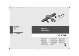


| Product type | Sawing station |
| Brand | BOSCH |
| Model | PLS 300 |
| Intended use | Jigsaw for wood, aluminum, plastics; tile cutting with PTC 1 set |
| Max. cutting length (crosscut 90°) | 315 mm |
| Max. cutting height | 25 mm |
| Horizontal miter angle | -45° to +45° |
| Vertical bevel angle | 0° to 45° |
| Weight (EPTA 01/2003) | 3.4 kg (PLS 300); 3.6 kg (set with PTC 1) |
| Max. blade tooth length | 76 mm |
| Compatible materials | Hardwood, softwood, aluminum, plastics, ceramic and earthenware tiles (up to 10 mm) |
| Main components | Base unit, slide with slot, stops, extensions, bridge, locking lever, angle indicator |
| Supplied accessories | PTC 1 set (tile cutter, stop, fracturing cones) – optional |
| Routine maintenance | Blow with compressed air or use a brush after each use |
| Repairability | Send to an authorized Bosch after-sales service; provide the 10-digit article number |
| Safety standards | Disconnect the tool before adjustment; assemble on a stable, flat surface; wear gloves for tiles |
| Customer service France | 0811360122 (local call rate) |
| Customer service Belgium/Luxembourg | +32 (070) 22 55 65 |
| Customer service Switzerland | +41 (044) 847 15 12 |
| Support website | www.bosch-do-it.com/pls300 |
Frequently Asked Questions - PLS 300 BOSCH
User questions about PLS 300 BOSCH
0 question about this device. Answer the ones you know or ask your own.
Ask a new question about this device
Download the instructions for your Measuring tool in PDF format for free! Find your manual PLS 300 - BOSCH and take your electronic device back in hand. On this page are published all the documents necessary for the use of your device. PLS 300 by BOSCH.
USER MANUAL PLS 300 BOSCH
Power Tools Division
70745 Leinfelden-Echterdingen
Germany
www.bosch-pt.com
1609929 W68 (2010.03) PS/224 UNI
1609929W68
PLS 300
PLS 300 Set

BOSCH
de Originalbetriebsanleitung en Original instructions fr Notice originale es Manual original pt Manual original it Istruzioni originali n Oorspronkelijke gebruiksaanwijzing da Original brugsanvisning sv Bruksanvisning i original no Original driftsinstruks
fi Alkuperäiset ohjeet el TpwrTtUTo 08nyiw Xphonc tr Original isletmet talimati pl Instrukcja oryginalna cs Puvodni navod k pouzivani sk Póvodny námod na použitie hu Eredeti hasznalatiutasitas ru OpunHaIbHoe pyKOBOaCT-BO IIO 3KcIaYatauIN uk OnprihaIbHa iHCTpyKciI 3 ekTnayataii
ro Instruetiuni originale bg OpunHaHa HnctpyKuia sr Originalno uputstvo za rad sl Izvirna navodila hr Originalne upute za rad et Alguparane kasutusjuhend Iv Instrukcijas originalvaloda It Originali instrukcija

2
Deutsch. 9
English. Page 17
Spanish. Page 33
Portuguese. Page 41
Italian. Page 49
Dutch. Page 57
Danish. Page 65
Swedish. Page 73
Norwegian. Page 80
Finnish. Page 87
Greek. Page 95
Turkish. Page 104
Polish. Page 112
Czech. Page 121
Slovak. Page 129
Hungarian. Page 138
General Safety Rules

Read all warning notes and instructions enclosed with the sawing station and the power tool to be mounted. Failure to follow the warnings and instructions may result in electric shock, fire and/or serious injury.
Safety Warnings for Sawing Stations
Pull the plug from the mains receptacle and/or remove the battery from the power tool before making adjustments on the tool or changing tool accessories. Unintentional switching on of the power tool is the cause of many accidents. - Assemble the sawing station in the proper manner before mounting the power tool. Safe guiding of the power tool is possible only when the sawing station is properly assembled. - Place the sawing station on a firm, level and horizontal surface. If the sawing station can slip off or wobbles, the power tool or the workpiece cannot be uniformly and securely guided. Attach the power tool securely to the sawing station before using it. Slipping off of the power tool on the sawing station can lead to loss of control. Take care that the cable of the power tool does not come between the base unit and the guide rail. When the cable is damaged or cut through, there is danger of electric shock. - Remove the power tool before modifying the sawing station or folding up the guide rails. The power tool can fall down, become damaged or cause injuries. Do not use a defective sawing station. Only an intact sawing station can guide the power tool securely.
Ensure that long and heavy workpieces do not affect the equilibrium of the sawing station. Long and/or heavy workpieces must be supported at the free end. Wear protective gloves when cutting tiles. Sharp edges develop on broken tiles and can cause injuries to the operator. Use the saw station only for cutting the materials listed under Intended Use. Marble or granite as well as tiles with a rough surface structure and natural stone tiles cannot be cut.
Functional Description
Intended Use
PLS 300: Together with the power tool, the sawing station is intended for sawing straight lengthway and crossway cuts in boards and profiles of hardwood and softwood, as well as aluminium and plastic.
Horizontal metre angles from a maximum of -45° to +45° as well as bevel angles from a maximum of 0° to 45° can be set.
The sawing station is intended for operation exclusively with jigsaws from the Bosch PST DIY program.
Only use the saw blades recommended by Bosch (see page 223). When using saw blades that are too thin, there is a danger that the cut runs out of center.
PLS 300 Set, PTC 1: Together with the tile cutter, the sawing station is intended for cutting ceramic and non-vitreous tiles to a maximum thickness of 10 mm.
Horizontal miter angles from a maximum of -45° to +45° can be set.
Product Features
The numbering of the product features refers to the illustration of the sawing station on the graphics pages.
PLS 300
1 Base unit 2 Scale for miter angle (horizontal) 3 Locking knob for height adjustment 4 Guide rail with sawing slot 5 Side stops of the guide rail 6 Support extension 7 Additional support 8 Bridge
9 End stop for bevel cuts 10 Locking lever of the guide rail 11 Alignment mark 12 Locking knob for various miter angles (horizontal) 13 Angle indicator (horizontal)
PTC 1*
14 Tile cutter 15 Stop with scale 16 Break-off cones
- only in combination with PLS 300 Set
Technical Data
| Sewing station | PLS 300 | PLS 300 Set (PLS 300 + PTC 1) | |
| Article number | 3 603 M04 0.. | 3 603 M04 1.. | |
| Sewing | |||
| - Max. cutting length for crossway cuts (90°) | mm | 315 | 315 |
| - Max. cutting height | mm | 25 | 25 |
| - Mitre/Bevel Angle | |||
| Horizontal | ° | ±45 | ±45 |
| Vertical | ° | ±45 | ±45 |
| Cutting tiles | |||
| - Max. cutting length for crossway cuts (90°) | mm | - | 340 |
| - Max. cutting height | mm | - | 10 |
| - Mitre/Bevel Angle | |||
| Horizontal | ° | - | ±45 |
| Weight according to EPTA-Procedure 01/2003 | kg | 3.4 | 3.4 + 0.2 |
Dimension of suitable saw blades
| Max. overall length | mm | 100 |
| Max. toothed length | mm | 76 |
Only use the saw blades recommended by Bosch (see page 223). When using saw blades that are too thin, there is a risk that the cut runs out of center.
Operation Sawing
Preparing for Operation
The saw station must be assembled depending on the respective sawing application:
Sawing Panels (e.g., laminate flooring panels) Sawing Profiles (e.g., baseboards)
The use of screws/bolts is not required.
Panel (cross section) (see figures A1-A3)
- Mount the support extensions 6 left and right to the base unit 1. Depending on the workpiece size, mount the additional supports 7 to the inner or outer guide of the support extensions.
- Loosen the locking knob 3 a few turns.
- Turn the locking lever 10 of the guide rail leftward and fold the guide rail 4 upward.
- Mark the desired cutting line on the workpiece.
- Place the workpiece with the visible side flat against the stop of the base unit 1.
- Fold the guide rail downward and align the workpiece to the cutting line of mark 11.
- Lock the guide rail 4 with locking lever 10.
- Tighten the locking knob 3.
Panel (mitre cuts) (see figure B)
The horizontal mitre angle can be set in the range from 45° (left side) to 45° (right side).
- Loosen locking knob 12.
- Turn the guide rail 4 left or right until the angle indicator 13 indicates the requested mitre angle.
- Tighten the locking knob 12 again.
For swift and precise adjustment of standard mitre angles, the guide rail engages at 0° and 45°.
- For additional worksteps, see "Panel (cross section)" on page 19.
Profile (bevel cuts) (see figures C1-C3)
- Mount the support extensions 6 left and right at the front position of the bridge 8.
- Fold the red end stop 9 by 180° to the rear.
- Loosen the locking knob 3 a few turns.
- Turn the locking lever 10 of the guide rail leftward and fold the guide rail 4 upward.
- Mark the desired cutting line on the workpiece.
- Place down the workpiece flat against the stop of the support extensions 6.
- Fold the guide rail downward and align the workpiece to the cutting line of mark 11.
- Lock the guide rail 4 with locking lever 10.
- Tighten the locking knob 3.
- Adjust the base plate of the jigsaw accordingly to the desired angle. Notes on the adjustment are given in the operating instructions of the jigsaw.
Note: The folded back red end stop 9 is used as the stop for the base plate of the power tool.
Panel (lengthway cuts, recesses) (see figure D)
- Loosen the locking knob 3 a few turns.
- Remove the guide rail 4 and the bridge 8 from the base unit 1.
- Mount the support extensions 6 left and right to the base unit 1. Depending on the workpiece length, mount the additional supports 7 reversed (see figure D) into the inner or outer guide of the support extensions.
Take care that the cutting line in the notched area is between the additional supports, to ensure that you do not saw into the saw station.
Note: When sawing lengthway cuts, the saw station is used only as a supporting surface. The workpiece cannot be clamped. Therefore, hold it tightly while sawing.
Working Advice
Only use the saw blades recommended by Bosch (see page 223). When using saw blades that are too thin, danger is given that the cut runs out of centre.
The base plate of the jigsaw must always be in the front position.
The thickness of the material to be cut depends on the sawing capacity of the respective jigsaw. For further information, see the operating instructions of your jigsaw.
To ensure optimal operational safety, the workpiece must always be affixed.
Sawing
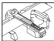
Position the base plate of the power tool in such a manner on the guide rail 4 that you always saw in the direction of locking knob 3. - Switch on the machine. - Saw through the workpiece applying uniform feed. - Switch off the machine and wait until the saw blade has come to a complete stop. - Remove the power tool from the guide rail and release the workpiece.
Transport
- Remove the power tool before transporting.
Practical Advice
The following tips are for performing length or litre cuts (90° / 45°)
| Problem | Cause | Corrective Measure |
| Cut runs out of centre | Guide rail 4 not affixed | Affix guide rail according to height of workpiece; provide for firm clamping of the workpiece |
| Saw blade too thin | Use the provided saw blade T144DP | |
| Sawing feed too high (apply less feed with power tool) | Saw through workpiece applying less and uniform feed | |
| Do not apply pressure against the side stops 5 | ||
| Angle adjustment of base plate to saw chain incorrect | Align base plate to saw chain and retighten | |
| Saw blade does not run in guide roller (see figure E) | Adjust guide roller in such a manner that the saw blade is guided (see operating instructions of the jigsaw) | |
| Wood surface unsatisfactory after cut | Workpiece was sawn with the visible side facing up | Saw workpiece with the visible side facing down (see figure A3) |
| Saw blade worn | Insert new saw blade | |
| Sawing feed too high (apply less feed with power tool) | Saw through workpiece applying less and uniform feed | |
| Do not apply pressure against the side stops 5 | ||
| Sawing was carried out with orbital action switched on | Switch orbital action off |
For working instructions and practical advice on the PLS 300 saw station, log onto: www.bosch-do-it.com/pls300
For further questions, please refer to our customer hotline:
Great Britain
Tel: +44 (0844) 736 0107
Australia, New Zealand
Phone: +61 (01300) 307 044
22 | English
Operation Cutting tiles
Preparing for Operation
When the sawing station is to be used for cutting tiles, the additional PTC 1 kit is to be used.
The stop 15 is supplied as two parts, folded together.
Before using for the first time, put the two parts of the stop 15 together, so that they cannot be taken apart afterwards.
Lengthway Cuts (see figures F1-F3)
- Loosen the locking knob 3 a few turns.
- Turn the locking lever 10 of the guide rail leftward and fold the guide rail 4 upward.
- Place stop 15 centred in the groove of bridge 8 and slide it flush into base unit 1.
- Mark the desired cutting line on the workpiece.
- Place down the workpiece with the visible side up, flat against the stop 15.
- Fold the guide rail 4 down and align the workpiece cutting line to the scale of the stop 15.
- Press down the guide rail 4 in the area of the workpiece with your flat hand.
- Tighten the locking knob 3.
- Lock the guide rail 4 with locking lever 10.
Diagonal Cuts (see figure G)
The horizontal miter angle can be set in the range from 45° (left side) to 45° (right side).
- Loosen locking knob 12.
- Turn the guide rail 4 left or right until the angle indicator 13 indicates the requested miter angle.
- Tighten the locking knob 12 again.
For swift and precise adjustment of standard miter angles, the guide rail engages at 0° and 45°.
- For additional worksteps, see "Lengthwise Cuts" on page 22.
Working Advice
Cutting Tiles (see figures H1-H3)
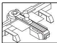
- Insert the tile cutter 14 into the sawing slot of the guide rail 4 above stop 15. The arrow on the tile cutter must face you. Pull the tile cutter 14 over the complete tile with uniform pressure.
- Remove the tile cutter 14 from the guide rail 4.
- Turn the locking lever 10 of the guide rail leftward and fold the guide rail 4 upward.
- Place the break-off cones 16 on a firm surface.
Place the tile on the break-off cones in such a manner that the break-off cones are positioned below the cutting line and at the edges of the tile.
For diagonal cuts, the break-off cones should be positioned below the cutting line and somewhat further toward the inside.
- Apply both of your thumb balls at the same time to the outer sides of the tile until the tile breaks.
Practical Advice
| Problem | Cause | Corrective Measure |
| Tile does not break along the cutting line | Scoring line not continuous from front to end | Apply more pressure (uniformly) when scoring the tiles and score over the complete surface |
| Tile cutter 14 incorrectly inserted | Insert tile cutter correctly (see figure H1) | |
| Surface structure of tile uneven | Apply more pressure (uniformly) when scoring and increase the scoring (cutting) speed | |
| Break-off cones incorrectly positioned when breaking the tile | Position break-off cones below the cutting line and at the edges of the tile (see figure H3) For diagonal cuts, position the break-off cones somewhat further toward the inside | |
| Scoring line not continuous from front to end | Increase scoring pressure when cutting the tiles |
For working instructions and practical advice on the PLS 300 saw station, log onto:
www.bosch-do-it.com/pls300
For further questions, please refer to our customer hotline:
Great Britain
Tel: +44 (0844) 736 0107
Australia, New Zealand
Phone: +61 (01300) 307 044
Maintenance and Service
Maintenance and Cleaning
If the saw station should fail or become damaged despite the care taken in manufacture and testing, repair should be carried out by an authorised customer services agent for Bosch power tools.
In all correspondence and spare parts orders, please always include the 10-digit article number given on the type plate of the saw station.
Cleaning
Remove dust and chips after each working procedure by blowing out with compressed air or with a brush.
Warranty Condition
Through faulty usage, sawing into the guide rail 4 or bridge 8 can occur. No warranty claims whatsoever shall arise thereof, as this does not affect the function of the saw station.
24 | English
After-sales Service and Customer Assistance
Our after-sales service responds to your questions concerning maintenance and repair of your product as well as spare parts. Exploded views and information on spare parts can also be found under:
www.bosch-pt.com
Our customer service representatives can answer your questions concerning possible applications and adjustment of products and accessories.
Great Britain
Robert Bosch Ltd. (B.S.C.)
P.O.Box 98
Broadwater Park
North Orbital Road
Denham
Uxbridge
UB 95HJ
Tel. Service: +44 (0844) 736 0109
Fax: +44 (0844) 736 0146
E-Mail: boschservicecentre@bosch.com
Ireland
Origo Ltd.
Unit 23 Magna Drive
Magna Business Park
City West
Dublin 24
Tel. Service: +353 (01) 466 67 00
Fax: +353 (01) 466 68 88
Australia, New Zealand and Pacific Islands
Robert Bosch Australia Pty. Ltd.
Power Tools
Locked Bag 66
Clayton South VIC 3169
Customer Contact Center
Inside Australia:
Phone: +61 (01300) 307 044
Fax: +61 (01300) 307 045
Inside New Zealand:
Phone: +64 (0800) 543 353
Fax: +64 (0800) 428 570
Outside AU and NZ:
Phone: +61 (03) 9541 5555
www.bosch.com.au
Republic of South Africa
Customer service
Hotline: +27 (011) 6519600
Gauteng - BSC Service Centre
35 Roper Street, New Centre
Johannesburg
Tel.: +27 (011) 493 93 75
Fax: +27 (011) 4930126
E-Mail: bsctools@icon.co.za
KZN - BSC Service Centre
Unit E, Almar Centre
143 Crompton Street
Pinetown
Tel.: +27 (031) 7 01 21 20
Fax: +27 (031) 7 01 24 46
E-Mail: bsc.dur@za.bosch.com
Western Cape - BSC Service Centre
Democracy Way, Prosperity Park
Milnerton
Tel.: +27 (021) 551 25 77
Fax: +27 (021) 5513223
E-Mail: bsc@zsd.co.za
Bosch Headquarters
Midrand, Gauteng
Tel.: +27 (011) 6519600
Fax: +27 (011) 6519880
E-Mail: rbsa-hq.pts@za.bosch.com
Disposal
The saw station, accessories and packaging should be sorted for environmental-friendly recycling.
Subject to change without notice.
Robert Bosch (France) S.A.S.
Bosch Service Center
Telegrafvej 3
2750 Ballerup
Tel. Service Center: +45 (4489) 8855
Fax: +45 (4489) 87 55
E-Mail: vaerktoej@dk.bosch.com
Disposal
Bosch Service Center
Telegrafvej 3
2750 Ballerup
Denmark
Tel.: +46 (020) 41 44 55
Fax: +46 (011) 187691
Waste management
Safety instructions
General safety instructions

Bosch San. ve Tic. A.S.
Ahi Evran Cad. No:1 Kat:22
Polaris Plaza
80670 Maslak/Istanbul
Customer Service: +90 (0212) 335 06 66
Customer Service Line: +90 (0212) 335 07 52
Liquidation
Robert Bosch Sp. z o.o.
Bosch Service Center PT
K Vapence 1621/16
692 01 Mikulov
Tel.: +420 (519) 305 700
Fax: +420 (519) 305 705
E-Mail: servis.naradi@cz.bosch.com
www.bosch.cz
Waste disposal
Application instructions
Use only Bosch recommended dust extraction hoses (see page 223). When using very fine dust extraction hoses, there is a risk of mixing with the sawing dust.
The extraction hose of the power tool must always be in the front position.
The thickness of the material to be sawed depends on the performance of the corresponding power tool. You will find the corresponding instructions in the operating manual of the power tool.
Application instructions
Cutting tiles (see figures H1-H3)
Insert the tile cutter 14 into the guide groove 4 on the base plate 15. The pin on the tile cutter must point towards your side. Push the tile cutter 14 to the end of the groove, pressing evenly on it. Pull the tile cutter 14 out of the guide groove 4. Turn the guide groove 4 to the left and lift the guide groove 4 upwards. Place the tile 16 on a stable surface. Place the tile on the guide groove in such a way that the guide groove is under the cutting line of the tile. When cutting, the guide groove must be positioned under the cutting line with slight lateral movement. Press simultaneously with both hands on the outer sides of the tile so that it breaks.
Russian | 149
Application tips
Component illustration
The numbering of the illustrated components refers to the illustration on the graphics page at the beginning of the manual.
PLS 300
1 Base plate 2 Scale for setting the horizontal cutting angle 3 Locking lever for the cutting depth 4 Guide for the cutting line 5 Side stops for the cutting line 6 Extraction hose 7 Extraction adapter 8 Crosspiece
9 Stop for vertical cutting angles 10 Lever for fixing the cutting line 11 Mark for cutting 12 Lever for fixing the vertical cutting angle and horizontal cutting angle 13 Indicator for the horizontal angle
PTC 1*
14 PANTKopi3 15 YItop 3i WkaAIO 16 YItop AIApo3AOMy
* ANWE B KOM6iHaui3 PLS 300 Set
Technical data
When using the device, the necessary complete set of PTC 1 is required.
The device is supplied in a partially disassembled state.
The pre-installation of the device parts is done in such a way that it cannot be further disassembled.
Adjustment of the device (Fig. A1-F3)
- Loosen the fixing handle 3 by turning it several times. Turn the adjusting screw of the clamp to the direct position of the plate and press the direct plate 4 upward. Insert the device 15 into the center of the groove of the limiter 8 and push it evenly to the base unit 1.
- Adjustment of the workpiece. - Place the workpiece with the side facing up in a horizontal position to the device 15. - Press the direct plate 4 down and align the workpiece adjustment with the device scale 15. - Press the handle of the direct plate 4 down to the workpiece. Tightly close the fixing handle 3. Fix the direct plate 4 with the help of lever 10.
Adjustment of the angle (Fig. A1. G)
The horizontal angle of adjustment can be set in the range from 45° (left) to 45° (right).
- Loosen the fixing handle 12. Turn the direct plate 4 left or right until the angle indicator 13 shows the required angle of adjustment.
- Tighten the fixing handle 12 again.
For precise and accurate adjustment of the angles, the direct plate enters the engagement of the angles 0° and 45°
Instructions for use. See "Commissioning" on page 156.
Work instructions
Saw chain (see figure A1-A3)
Insert the chain 14 into the groove for the guide bar 4 and around the sprocket 15. The chain direction must match the arrow on your guide bar. Pull the chain 14 to the end of the guide bar, pressing evenly on it. Remove the chain 14 from the guide bar 4. Turn the adjusting wheel 10 counterclockwise and lift the guide bar 4 upward. Place the guide bar with the slot 16 on a stable surface.
Place the chain on the guide bar so that the drive links are positioned in the groove of the guide bar and along the edges of the bar.
Before mounting the guide bar and chain, it is necessary to place them under the chain guard with the sprocket slightly recessed inward.
Press evenly on both sides of the chain while pulling it outward, so that it does not come off.
After-sales service and application service
Bosch Service Center
Str. Horia Macelariu Nr. 30-34,
013937 Bucuresti
Tel. Service scule electrice: +40 (021) 4 05 75 40
Fax: +40 (021) 405 7566
E-Mail: infoBSC@ro.bosch.com
Tel. Consultanta tehnica: +40 (021) 4 05 75 39
Fax: +40 (021) 405 7566
E-Mail: infoBSC@ro.bosch.com
www.bosch-romania.ro
Disposal
The tool must not be disposed of with screws.
Panels (cross cuts) (See figure A1-A3)
Insert the moistened support surface flush with the base plate. Depending on the size of the part, insert the support plates into the inner or outer recesses of the support surface. - Loosen the clamping lever about 10 turns. Turn the guide to the left until it stops to clamp the guide. Then loosen the guide and turn it upwards. - Mark the cutting line on the part. Place the part with its front side on the support base. Lower the guide and align the part so that the cutting line coincides with the marking 11. - Clamp the guide with about 10 turns. Then tighten the clamping lever.
Panels (cutting surfaces in horizontal plane) (See figure B)
The cutting angle in the horizontal plane can be adjusted from -45° (left) to +45° (right).
- Loosen the clamping lever 12. Turn the guide 7 to the left or right until the arrow 13 points away from you.
- Then tighten the clamping lever to secure the angle.
For quick and precise adjustment of the standard angles in the range of 0° and 45°, the guide has a stop.
- For more detailed work steps, see "Panels (cross cuts)" on page 169.
Bevels (cuts under inclination in vertical plane) (See figures C1-C3)
Insert the moistened support surface flush into the front base plate 8. - Turn the limit stop 9 by 180°. Loosen the clamping lever about 10 turns. Turn the guide to the left until it stops to clamp the guide. Then loosen the guide and turn it upwards. - Mark the cutting line on the part. Place the part with its front side on the work surface 6 and align it against the support. Lower the guide and align the part so that the cutting line coincides with the marking 11. Clamp the guide with about 10 turns. - Then tighten the clamping lever.
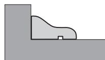
- The test probe base is designed in a way that is unique and fits the standard. The instructions for how to connect it are given in the manual for the test probe.
Warning: The red trigger moves backward and limits the 9 functions as a safety stop for the main base and the electrical instruments.
General safety instructions


- PLS
- PLS 300 SET
- BOSCH
- GENERAL SAFETY RULES
- SAFETY WARNINGS FOR SAWING STATIONS
- FUNCTIONAL DESCRIPTION
- INTENDED USE
- PRODUCT FEATURES
- PTC
- TECHNICAL DATA
- DIMENSION OF SUITABLE SAW BLADES
- OPERATION SAWING
- PREPARING FOR OPERATION
- PANEL (CROSS SECTION) (SEE FIGURES A1-A3)
- PANEL (MITRE CUTS) (SEE FIGURE B)
- PROFILE (BEVEL CUTS) (SEE FIGURES C1-C3)
- PANEL (LENGTHWAY CUTS, RECESSES) (SEE FIGURE D)
- WORKING ADVICE
- SAWING
- TRANSPORT
- PRACTICAL ADVICE
- GREAT BRITAIN
- ENGLISH
- OPERATION CUTTING TILES
- LENGTHWAY CUTS (SEE FIGURES F1-F3)
- DIAGONAL CUTS (SEE FIGURE G)
- CUTTING TILES (SEE FIGURES H1-H3)
- MAINTENANCE AND SERVICE
- MAINTENANCE AND CLEANING
- CLEANING
- WARRANTY CONDITION
- AFTER-SALES SERVICE AND CUSTOMER ASSISTANCE
- WWW.BOSCH-PT.COM
- IRELAND
- AUSTRALIA, NEW ZEALAND AND PACIFIC ISLANDS
- REPUBLIC OF SOUTH AFRICA
- CUSTOMER SERVICE
- GAUTENG - BSC SERVICE CENTRE
- KZN - BSC SERVICE CENTRE
- WESTERN CAPE - BSC SERVICE CENTRE
- BOSCH HEADQUARTERS
- DISPOSAL
- WASTE MANAGEMENT
- SAFETY INSTRUCTIONS
- GENERAL SAFETY INSTRUCTIONS
- LIQUIDATION
- WASTE DISPOSAL
- APPLICATION INSTRUCTIONS
- COMPONENT ILLUSTRATION
- ADJUSTMENT OF THE DEVICE (FIG. A1-F3)
- ADJUSTMENT OF THE ANGLE (FIG. A1. G)
- WORK INSTRUCTIONS
- SAW CHAIN (SEE FIGURE A1-A3)
- PANELS (CROSS CUTS) (SEE FIGURE A1-A3)
- PANELS (CUTTING SURFACES IN HORIZONTAL PLANE) (SEE FIGURE B)
- BEVELS (CUTS UNDER INCLINATION IN VERTICAL PLANE) (SEE FIGURES C1-C3)
Brand : BOSCH
Model : PLS 300
Category : Measuring tool