
SUPERTRONIC 2SE - Machine tool ROTHENBERGER - Free user manual and instructions
Find the device manual for free SUPERTRONIC 2SE ROTHENBERGER in PDF.

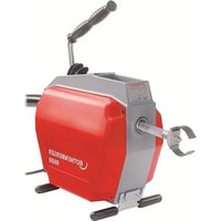
| Product type | Electric threading machine |
| Brand | ROTHENBERGER |
| Model | SUPERTRONIC 2SE |
| Dimensions (L x W x H) | 570 x 435 x 360 mm |
| Weight (without accessories) | 46 kg |
| Machinable materials | Steel, stainless steel |
| No-load speed | 38 rpm |
| Motor power | 1150 W |
| Frequency | 50/60 Hz |
| Power supply | 230 V single-phase |
| Die head | Automatic 1/2" - 2" |
| Dies supplied | 1/2" - 3/4", 1" - 2" (optional 1/4" - 3/8") |
| Sound pressure level | 85 dB(A) (KpA 3 dB(A)) |
| Sound power level | 96 dB(A) (KWA 3 dB(A)) |
| Total vibrations | 2.5 m/s² (K=1.5 m/s²) |
| Main functions | Threading, cutting, internal reaming |
| Lubrication | Oil pump with integrated reservoir |
| Integrated accessories | Pipe cutter, internal reamer, die head |
| Safety | Foot switch, emergency stop, overload protection |
| Routine maintenance | Oil change, carbon brush replacement, blades and rollers |
| Repairability | By Rothenberger authorized service center |
Frequently Asked Questions - SUPERTRONIC 2SE ROTHENBERGER
User questions about SUPERTRONIC 2SE ROTHENBERGER
0 question about this device. Answer the ones you know or ask your own.
Ask a new question about this device
Download the instructions for your Machine tool in PDF format for free! Find your manual SUPERTRONIC 2SE - ROTHENBERGER and take your electronic device back in hand. On this page are published all the documents necessary for the use of your device. SUPERTRONIC 2SE by ROTHENBERGER.
USER MANUAL SUPERTRONIC 2SE ROTHENBERGER
natural_image
Technical line drawing of a mechanical device with no visible text or symbolsEN Instructions for use
rothenberger.com
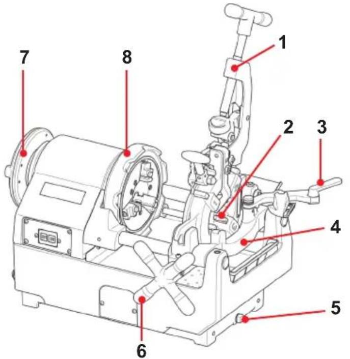
OverviewA
no.: 1500004021 SUPERTRONIC 2SE, Standard die head, BSPT R1/2-2", 230V no.: 1500004023 SUPERTRONIC 2SE, Automatic die head, BSPT R 1/2-2", 230V no.: 1500004026 SUPERTRONIC 2SE, Automatic die head, BSPT R 1/2-2", 110V no.: 1500004028 SUPERTRONIC 2SE, Automatic die head, NPT 1/2-2", 230V
B Clamping
natural_image
Mechanical diagram showing a rotating shaft mounted on an electric motor (no text or symbols)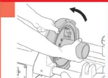
natural_image
Illustration of hands operating a mechanical device with an arrow indicating rotation (no text or symbols present)
natural_image
Illustration of a hand operating a mechanical device with a rotating arrow indicating rotation (no text or symbols present)C Cutting
natural_image
Technical line drawing of a mechanical device with no visible text or symbolsD Reaming
natural_image
Technical line drawing of a mechanical device with internal components and directional arrows indicating motion (no text or symbols)
natural_image
Technical line drawing of a mechanical component with labeled parts (no text or symbols)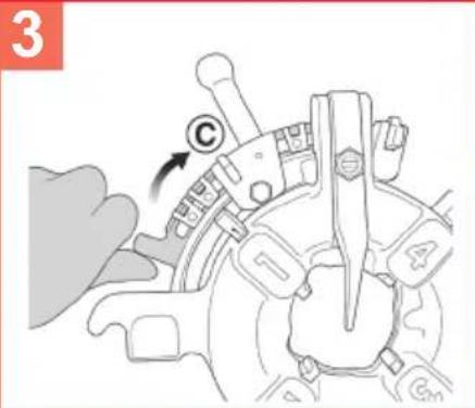
Threading
G
Changing thread size
F
natural_image
Technical line drawing of a mechanical assembly with a tool inserted, showing no text or symbols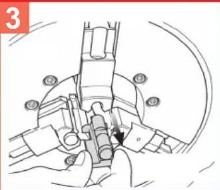
natural_image
Illustration of hands assembling or adjusting mechanical components with a curved arrow indicating motion (no text or symbols present)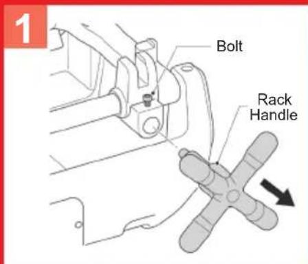
Intro
EU-DECLARATION OF CONFORMITY
We declare on our sole accountability that this product conforms to the standards and guidelines stated.
DECLARATION EU DE CONFORMITÉ
Manufacturer/ authorized representative signature

Thomas Bamberger
i. V. Maximilian Gottschalk
Managing Director Head of Innovation Management
Kelkheim, 11.10.2022
D-65779 Kelkheim/Germany

Intro
| DEUTSCH - Originalbetriebsanleitung!Bedienungsanleitung bitte lesen und aufbewahren! Nicht wegwerfen! Bei Schäden durch Bedienungsfehler erlischt die Garantie! Technische Änderungen vorbehalten! | Seite 2 |
| ENGLISHPlease read and retain these directions for use. Do not throw them away! The warranty does not cover damage caused by incorrect use of the equipment! Subject to technical modifications! | Page 17 |
| FRANÇAISLire attentivement le mode d'emploi et le ranger à un endroit sûr! Ne pas le jeter! La garantie est annulée lors de dommages dûs à une manipulation erronée! Sous réserve de modifications techniques! | Page 31 |
| ESPANOL¡Por favor, lea y conserve el manual de instrucciones! ¡No lo tire! ¡En caso de daños por errores de manejo, la garantía queda sin validez! Modificaciones técnicas reservadas! | Página 46 |
| ITALIANOPer favore leggere e conservare le istruzioni per l'uso! Non gettarle via! In caso di danni dovuti ad errori nell'uso, la garanzia si estingue! Ci si riservano modifiche tecniche! | Pagina 62 |
| NEDERLANDSLees de handleiding zorgvuldig door en bewaar haar goed! Niet weggooien! Bij schade door bedieningsfouten komt de garantieverlening te vervallen! Technische wijzigingen voorbehouden! | Bladzijde 78 |
| PORTUGUESQueiram ler e guardar o manual de instruções! Não deitar fora! Em caso de avarias por utilização incorrecta, extingue-se a garantía! Reservado o direito de alterações técnicas! | Pagina 93 |
| DANSKLæs betjeningsvejledningen, og gem den til senere brug! Smid den ikke ud! Skader, som måtte opstå som følge af betjeningsfejl, medfører, at garantien mister sin gyldighed! Ret til tekniske ændringer forbeholdes! | Side 108 |
| SVENSKALås igenom bruksanvisningen och förvara den väl! Kasta inte bort den! Garantin upphör om apparaten har använts eller betjänats på ett felaktigt sätt! Med reservation för tekniska ändringar! | Sida 122 |
| NORSKLes bruksanvisningen og oppbevar den vel! Ikke kast den! Oppstår skader på grunn av betjeningsfeil opphører garantiens gyldighet! Tekniske forandringer forbeholdes! | Side 136 |
| SUOMILue ja säilytä tämä käyttöohje! Älä heitä pois! Takuu ei kata käyttövirheistä aiheutuvia vahinkoja! Oikeudet teknisiin muutoksiin pidätetään! | Sivulta 150 |
| POLSKIInstrukcję obsługi proszę przeczytać i zachować! Nie wyrzucać! Przy uszkodzeniach wynikajacych z blędów obsługi wygasa gwarancja! Zmiany techniczne zastrzeżone! | Strony 164 |
| CESKYNavod k obsluze si prosim přečtěte a uschovejte jej! Nevyhazujte jej! V pripade poškozeni zpusobenem chybnou obsluhou zanika zaruka! Technicke změny jsou vyhrazeny! | Stránky 180 |
| TURKÇEKullanim açıklamalarini lütfen dikkatlice okuyunuz ve bir yerde muhafaza ediniz! Çöpe atmayiniz! Kullaniminda yapılan hatalar, garantinin silinmesine neden olur! Teknik deðipiklikler yapma hakkimiz saklidir! | Sayfa 195 |
| MAGYARKérjük, olvassa el és őrizze meg a kezelési utasítást! Ne dobja el! A helytelen kezelésböl származó károsodások esetén megszůnik a jótállás! Müszaki változtatások fenntartva! | Oldaltól 210 |
| ESTUPalun lugege kasutusjuhend läbi ja hoidke alles! Ärge visake ära! Kä-sitsemisvigadest tingitud kahjustuste korral kaotab garantii kehtivuse! Oigus tehnilisteks muudatusteks reserveeritud! | Lehekülg 225 |
| LIETUVOSPerskaitykite naudojimo instrukciją ir pasilikite ją! Neišmeskite! Garan-tija nebus taikoma gedimams, atsiradusiems dėl netinkamo naudojimo! Pasiliekama teisė daryti techninius pakeitimus! | Pusla-pis 239 |
| LATVIESULüdzu, izlasiet un uzglabājiet lietošanas instrukciju! Nemest prom! Ja ir bojājumi ekspluatācijas kjūdas dėl, garantija zaudė spēku! Paturēt tehniskas izmainas! | Lappuse 253 |
| ΕΛΛΗΝΙΚΑΟδηγίες χειρισμού παρακαλείσθε να τις διαβάσετε και να τις φυλάσσετε! Μην τις πετάξετε! Σε ζημιες από σφάλματα χειρισμού παυει να ισχύει η εγγύηση! Με επιφύλαξη για τεχνικές αλλαγές! | Σελίδα 267 |
| РУССК ИЙПрочтите инструкцию по эксплуатации и сохраняйте её для дальнейшего использования! В случае поломки инструмента из-за несоблюдения инструкции клиент теряет право на обслуживание по гарантии! Возможны технические изменения! | Страница 283 |
Inhalt Seite
Schneidleistung .... BSPT R 1/4" ... 2"(60.5mm), NPT 1/4" ... 2" (60.5mm), Bolzengewinde 3/8" ... 2" (60.5mm)
natural_image
Technical line drawing of a mechanical assembly with no visible text or symbolsÖlablassschraube
1.1 Intended use....18
1.2 General safety instructions....18
1.3 Special safety instructions....19
2 Technical Data 21
3 Function of the Unit 21
3.1 Overview (A)....21
3.2 Functional description....21
4 Preparations for operation....22
4.1 Transporting the threading machine 22
4.2 Setting up the machine....22
4.3 Electrical connection....22
4.4 The thread cutting oil....23
4.5 Checking the thread cutting oil....23
4.6 Setting the supplied thread cutting oil quantity 23
4.7 Draining off the oil....24
5 Carrying and Storage (I) 24
6 Operation of the threading machine 24
6.1 Clamping the workpieces (B)....24
6.2 Cutting the workpiece with the pipe cutter (C) 24
6.3 Reaming the workpieces (D)....25
6.4 Removing and installing the dies (E)....25
6.5 Installing and removing the thread-tapping head into and out of the bed carriage 25
6.6 Changing the thread size (F) 26
6.7 Tapping threads (G) 26
6.8 Setting the thread length....26
6.9 Setting the thread depth 27
6.10 Removing the workpiece 27
6.11 Cleaning after use 27
7 Maintenance and inspection....27
7.1 Changing the internal deburrer blade 27
7.2 Changing the pipe cutter cutting wheel 28
7.3 Replacement of Gear Pump 28
7.4 Changing the clamping jaw inserts (H) 28
7.5 Replacement of Carbon Brush....29
7.6 Daily inspection....29
8 Troubleshooting....29
9 Accessories....30
10 Customer service....30
11 Disposal....30
11.1 Metal, electrical and electronic parts....30
11.2 Oils and lubricants 30
Markings in this document:

Markings in this document!
This sign warns against the danger of personal injuries.

Caution!
This sign warns against the danger of property damage and damage to the environment.

Call for action
1 Safety Notes
1.1 Intended use
The threading machine SUPERTRONIC 2SE may only be used for cutting off, making and deburring threads as described in Chapter 2 "Technical data".
The SUPERTRONIC 2SE threading machine may only be operated with suitable die heads that have been inspected and recommended by ROTHENBERGER Werkzeuge GmbH, and with dies as described in Chapter 2 “Technical data”.
The supplied safety pedal carries the GS approval of the professional liability insurers' association and is compulsory for using the machine in the Federal Republic of Germany.
Never make technical or design modifications to the thread-tapping machine and to the accessory parts.
→ This would render the operating permit void and would represent an accident and injury risk.
When using electrical tools and machines, basic safety measures must be observed and followed in order to provide protection against electric shock, injury and fire risks. Read the instructions precisely before using the machine.
Always keep the safety instructions to hand.
1.2 General safety instructions

ATTENTION! When using electric tools, the following fundamental safety measures must be taken to prevent electric shock, injury or fire.
Read all of these instructions before you use the electric tool, and store the safety instructions properly.
Service and maintenance:
1 Regular cleaning, maintenance and lubrication. Always unplug electrical plug before any adjustment, maintenance or repair.
2 Have your device repaired only by qualified experts and only with original replacement parts. This ensures the continued safety of the device.
Working safely:
1 Keep your work area orderly. A messy work area can cause accidents.
2 Consider environmental influences. Do not expose electric tools to rain. Do not use electric tools in damp or wet environments. Keep the work area well lit. Do not use electric tools where there is a risk of fire or explosion.
3 Protect yourself from electric shock. Avoid physical contact with earthed parts (such as pipes, radiators, electric stoves or cooling devices).
4 Keep other people away. Do not let other people — especially children — touch the electric tool or its cable. Keep them away from the work area.
5 Store electric tools safely when they are not in use. Unused electric tools should be kept in a dry, high or closed area, out of reach of children.
6 Do not overload your electric tool. Work is better and safer within the performance range indicated.
7 Use the right electric tool. Don't use low-performance machines for heavy-duty jobs. Do not use the electric tool for purposes for which it was not intended. For example, do not use a portable circular saw for cutting tree branches or logs.
8 Wear proper clothing. Do not wear loose clothing or jewellery, as they can get caught in moving parts. When working outdoors, wear slip-resistant shoes. Wear a hairnet over long hair.
9 Use protective gear. Wear safety glasses. Wear a breathing mask during work that creates dust.
10 Connect the dust extraction equipment. If there are connections to dust extraction and collection equipment, make sure that they are connected and properly used.
11 Do not use the cable for purposes for which it was not intended. Never use the cable to pull the plug from the socket. Protect the cable from heat, oil and sharp edges.
12 Secure the work piece. Use clamps or a vice to hold the work piece firmly. They will hold it more securely than your hand can.
13 Avoid abnormal postures. Make sure to stand securely and always keep your balance.
14 Maintain your tools with care. For better and safer work, keep cutting tools sharp and clean. Follow the instructions for lubrication and changing tools. Regularly inspect the electric tool's connection cable, and if it is damaged, have it replaced by an authorized expert. Regularly check extension cords and replace them if they are damaged. Keep the handles dry, clean and free of oil and grease.
15 Pull the plug from the socket. When not using the electric tool, before maintenance or when changing tools, such as saw blades, drills and cutting bits.
16 Do not leave any tool keys inserted. Before switching on, check to see that keys and adjustment tools have been removed.
17 Avoid unintentional activation. When plugging the tool in, make sure that the switch is turned off.
18 Use outdoor extension cords. When outdoors, use only extension cords that are approved and appropriately marked.
19 Be alert. Pay attention to what you do. Approach your work sensibly. Do not use the electric tool when you are distracted.
20 Check the electric tool for damage. Before using the electric tool, you must inspect safety equipment or slightly damaged parts carefully to ensure that they work properly and as intended. Check to see that the moving parts operate freely and don't stick, and to make sure no parts are damaged. All parts must be mounted properly and meet all the conditions for ensuring trouble-free operation of the electric tool.
Damaged safety equipment and parts must be properly repaired or replaced by a professional facility, unless otherwise indicated in the user manual. Damaged switches must be replaced by a customer service facility.
Never use an electric tool whose switch cannot be turned on and off.
21 Caution. Using other insertion tools and accessories may cause injury.
22 Have your tool repaired by an electrical expert. This electric tool meets applicable safety requirements. Repairs must be made only by an electrical expert using original replacement parts. Otherwise accidents may occur.
1.3 Special safety instructions
Keep floor dry and free of slippery materials such as oil. Slippery floors invite accidents.
Restrict access or barricade the area when work piece extends beyond machine to provide a minimum of one metre clearance from the work piece. Restricting access or barricading the work area around the work piece will reduce the risk of entanglement.
Keep all electrical connections dry and away from the floor. Do not touch plugs or the machine with wet hands. These safety precautions reduce the risk of electric shock.
Keep hands away from rotating pipes or fittings. Switch off the machine before cleaning pipe threads or screwing on fittings. Let the machine come to a complete standstill be-
fore touching the pipe. This procedure reduces the possibility of getting trapped by rotating parts.
In order to avoid safety hazards, if the power supply cord needs to be replaced, this must be done by ROTHENBERGER or by an after-sales service centre that is authorized to repair ROTHENBERGER power tools.
Never put fingers, your face, hair or other parts of the body, or loose, wide items of clothing into the operating and intake areas of rotating parts (workpiece, clamping chuck, centring chuck). Do not wear jewellery (rings, chains etc.). Risk of injury and accidents!
In the event of faults (unusual smell, vibrations, unusual noises) during work with the SUPER-TRONIC 2SE, it is essential to immediately press the safety pedal and perform an EMERGENCY STOP of the machine!
If the machine is running, it is prohibited to hold the workpieces manually or to perform similar work, and to fit and remove parts such as filters, valves, pipe sections etc.!
Wear safety clothing! Wear a safety mask to provide protection against splashes of thread cutting oil as well as any chlorine gas vapours (from thread cutting oil burning on hot tool and workpiece surfaces)! Wear a safety hat to cover and protect long hair. Wear safety gloves when changing the dies, the pipe cutting wheel and the pipe deburrer. Wear safety gloves when changing the tool and workpiece. The thread and dies get hot during thread cutting! Wear safety footwear. Risk of injury (slipping) on any escaping thread cutting oil! Risk of injury from wet, slippery and possibly off-centre machine parts when changing the tool!
Do not remove metal chips using compressed air! There is a risk of eye injuries and loss of eyesight!
Ensure sufficient ventilation during indoor use (closed rooms). The permissible ambient temperature is between 0^ C and 40^ C!
Before changing the die head, the cutting wheel, the pipe deburrer, always switch off the machine and pull out the mains plug (de-energized operation!)
After it has been switched off, the machine still coasts for a while until it comes to a standstill.
Do not touch any parts before the machine is completely stationary and the mains plug has been pulled out!
In the case of the threaded pipes, carry out a pressure test in order to ensure that no gas or water can escape after the pipes are fitted!
Power tool plugs must match the outlet. Never modify the plug in any way. Do not use any adapter plugs with earthed (grounded) power tools. Unmodified plugs and matching outlets will reduce risk of electric shock
Use the power tool, accessories and tool bits etc., in accordance with these instructions, taking into account the working conditions and the work to be performed. Use of the power tool for operations different from those intended could result in a hazardous situation.
Follow instructions on proper use of this machine. Do not use for other purposes such as drilling holes or turning winches.
Secure machine to bench or stand. Support long heavy pipe with pipe supports.
While operating the machine, stand on the side where the REVERSE/OFF/FORWARD or FORWARD/REVERSE switch is located.
Keep covers in place. Do not operate the machine with covers removed.
Do not use this machine if the footswitch is broken or missing.
Setting-up or fixing power tool in a stable position as appropriate for power tools which can be mounted on a support or fixed to the floor.
Inspect extension cords periodically and replace if damaged.
Before further use of tool, it should be carefully checked to determine that it will operate properly and perform its intended function.
Have defective switches replaced by an authorized service centre.
The use of any accessory or attachment other than one recommended in this instruction manual may present a risk of personal injury.
2 Technical Data
Cutting capacity .... BSPT R 1/4" ... 2"(60.5mm), NPT 1/4" ... 2" (60.5mm),
Bolt thread 3/8" ... 2" (60.5mm)
Cutting material .... Steel, Stainless Steel
Speed under no load 38min^-1 (rpm)
Single-phase universal motor ..... 1150W
Frequency 50/60 Hz
Dimensions (LxWxH) 570 × 435 × 360mm
Weight (without accessories) ..... 46kg
Die head ...... Automatic-die head 1/2" – 2" or 2 SE die heads
Dies 1/2" - 3/4", 1" - 2" (Optional 1/4" - 3/8" no. 56369)
Noise pressure level (LpA) 85 dB (A) | KpA 3 dB (A)
Sound power level (LWA) 96 dB (A) | KWA 3 dB (A)
The noise level during operation can exceed 85 dB (A). Wear hearing protection!
Measured values determined in accordance with EN 61029-1.
Vibration total value 2,5 m/s ^2 | K= 1,5m/s ^2
The vibration level given in this information sheet has been measured in accordance with a standardized test given in EN 61029 and may be used to compare one tool with another. It may be used for a preliminary assessment of exposure.

The declared vibration emission level represents the main applications of the tool.
However if the tool is used for different applications, with different accessories or insertion tools or is poorly maintained, the vibration emission may differ. This may significant-
ly increase the exposure level over the total working period.
An estimation of the level of exposure to vibration should also take into account the times when the tool is switched off or when it is running but not actually doing the job. This may significantly reduce the exposure level over the total working period.
Identify additional safety measures to protect the operator from the effects of vibration such as: maintain the tool and the accessories, keep the hands warm, organization of work patterns.
3 Function of the Unit
3.1 Overview (A)
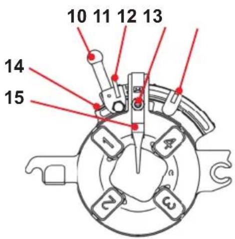
1 Pipe cutter 8 Clamping chuck
2 Dies 10 T-handle
3 Internal deburrer 11 Locking lever
4 Tool carriage 12 Selector pin
5 Oil drainage screw 13 Selector block
6 Feeder hand wheel 14 Cam plate
7 Centring chuck 15 Locking lever
3.2 Functional description
Threads are cut or turned on workpieces such as pipes or rods in the thread-tapping machine SUPERTRONIC 2SE.
The machine consists of:
- a drive motor that rotates the centring chuck
- a clamping chuck for securing the workpiece
- a pipe cutter for cutting the workpiece to length
- an internal deburrer
- a thread-tapping head for making a thread on the workpiece
-
an oil pump that lubricates and cools with thread-tapping oil
-
a tool carriage guided on both sides with a toothed feed
- a chip collecting and oil trough
- a safety pedal
- a coasting restrictor
4 Preparations for operation
4.1 Transporting the threading machine

Bend at the knees when lifting the machine so as to protect your back against over-stressing.
Weighing more than 35 kg, you need 2 people to carry the machine safe!
| ! Fix the tool carriage so that it cannot move while the machine is being transported. Hold the machine securely by its base to lift it. Do not hold the machine by its centring chuck or the internal deburrer when carrying it! |
| ! If the machine is transported with the threac-tapping oil still inside, the oil might splash out onto clothing due to vibrations! |
| ! Thread-tapping oil on the surface of the machine makes it slippery. Ensure that it does not slip out of your hands when you lift it! |
4.2 Setting up the machine
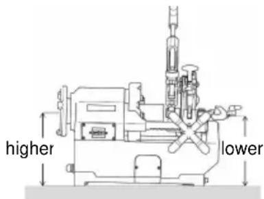
Set up the machine in a dry location! Place the machine on a level surface without spaces or on a flatwork bench. The centring chuck must be higher in relation to other parts of the machine so that no thread-tapping oil can escape via the pipe being machined and contaminate the floor!

If you do not have a clear view of the dangerous area formed by the machine and the revolving workpiece, the full length of the revolving workpieces must be reduced or the dangerous area must be safeguarded by a cordon or warning signs! The safety fixtures must be set up and secured firmly. If supports are used for this purpose, they must be height-adjustable and sturdy and there must be a sufficient number of them!
4.3 Electrical connection
Do not place either the machine or workpieces on the connecting cable, otherwise the cable could be damaged and electrical current could be exposed, presenting an electric shock hazard!
Never touch the mains plug and mains cable with wet hands. Electric shock hazard!
When connecting the machine to the electricity supply, always ensure that the switch is set to "OFF", otherwise there is a risk that the machine will start up unnoticed and unsupervised when the power is connected!
It is essential that the voltage on the machine's rating plate corresponds to the power source, otherwise the machine could get hot, smoke could develop, start a fire and cause damage!
The integrated overload protection automatically stops the machine in the event of an overload or power fluctuations! Switching back on is not possible until one minute has elapsed!
Use the extension cable H07 RN 3 x 1.5 mm2! The cable should not be longer than 30m!
4.4 The thread cutting oil

For tapping, use ROTHENBERGER high-performance thread-tapping oil art. no. 65010.
This oil is not suitable for tapping drinking water pipes!
Alternatively, you can use ROTHENBERGER high-performance thread-tapping fluid, art. no. 65015. This fluid is suitable for tapping all pipelines including drinking water pipelines.

Keep thread-tapping oils out of the reach of children!

Do not thin thread-tapping oil or mix it with other oils! If the thread-tapping oil becomes mixed with water, it turns milky-white, its quality is reduced and the tapped thread displays lower quality. It is then recommended to change the oil
Avoid direct sunlight and store the oil in a dark place!
Close the oil container tight after use in order to prevent the ingress of dirt and water!

ATTENTION PERSONS WITH ALLERGIES!
Thread-tapping oil that lands on the skin can cause skin irritation, inflammation and allergic reactions! When handling oil, wear protective clothing and cover exposed skin areas. If your skin comes into contact with oil, wash it immediately with tap water and soap. If thread-tapping oil burns onto hot workpiece or tool surfaces, this can produce toxic vapours or gases (e.g. chlorine gas when red oil burns). If you have accidentally inhaled this oil mist or oil vapours, go out into the fresh air immediately and consult a doctor without delay!
4.5 Checking the thread cutting oil

When cleaning, servicing, inspecting or repairing the machine, it is essential to switch it off and pull out the mains plug (de-energised operation)!
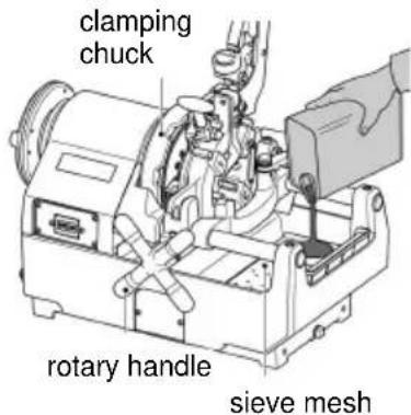
→ Turn the rotary handle clockwise in order to move the tool carriage to the clamping chuck.
→ On the right side of the machine, fill up with the thread tapping oil to the level of the sieve mesh.
→ Ensure that the machine is still switched off and insert the mains plug back into the socket.
→ Switch on the machine and ensure that the thread-tapping oil runs out of the thread-tapping head to the cutting jaws. If the right amount of oil is not supplied, regulate it with the oil adjustment screw.
4.6 Setting the supplied thread cutting oil quantity

When cleaning, servicing, inspecting or repairing the machine, it is essential to switch it off and pull out the mains plug (de-energised operation)!
→ Ensure that the oil tank is filled with oil up to the level of the sieve mesh.
→ If the amount of thread-tapping oil running via the thread tapping head does not meet the requirements, the supplied amount must be adjusted with the aid of the oil adjustment screw.
→ Undo the locking nut of the oil adjustment screw.
→ Turning the oil adjustment screw clockwise increases the amount of oil delivered and turning it anti-clockwise reduces the amount.
→ Tighten the locking nut firmly after making the adjustment.

4.7 Draining off the oil

It is essential to also observe the safety and disposal regulations in Chapter 11!
natural_image
Technical line drawing of a mechanical assembly with no visible text or symbolsOil drainage screw
5 Carrying and Storage (I)
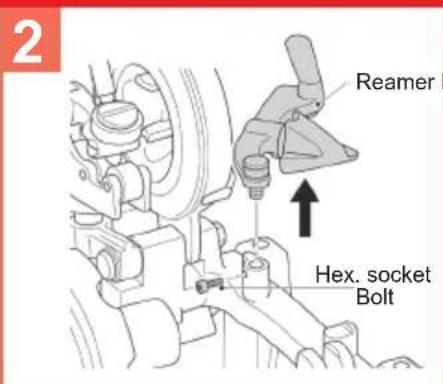
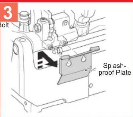
Rack Handle, Reamer, and Splashproof Plate can be removed easily.
By removing Rack Handle, Reamer, and Splashproof Plate, it becomes compact and easy to store and carry.
Removing Rack Handle (1)
→ Loosen Bolt to fix Rack Handle.
→ Pull out Rack Handle.
Removing Reamer (2)
→ Remove Bolt to fix Reamer.
→ Pull out Reamer upward.
Removing Splashproof Plate (3)
→ Loosen Bolts to fix Splashproof Plate.
→ Slide Splashproof Plate upward slightly and remove it.
6 Operation of the threading machine
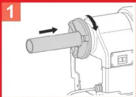
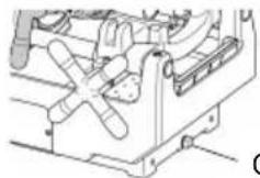
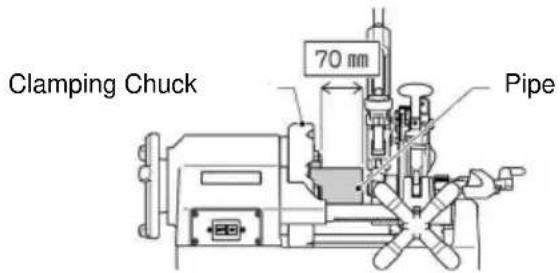
6.1 Clamping the workpieces (B)
The tool carriage can make contact with the frame before the thread cutting process has ended and the clamping chuck and the machine can be damaged as a result! A clearance of at least 70 mm must therefore be maintained between the threadcut on the workpiece and the clamping chuck!
→ Move the pipe cutter and the die head up so that they are not in the way and position the internal deburrer on the rear side.
→ Insert the workpiece from the centring chuck side (B1) and tighten the centring chuck (B2).
→ Hold the workpiece on the clamping chuck side securely with your right hand and gradually tighten it with the clamping chuck (B3).
→ Ensure that the three clamping jaws are in contact with the workpiece.
If the three clamping jaws are not in contact with the workpiece, it will wobble and neither cutting nor thread cutting can be performed correctly!
→ Clamp the workpiece securely and tighten it very firmly.
In the case of long or heavy pipes, it is essential to use the pipe support Art. No. 56047 in order to prevent the workpiece wobbling or twisting while it is being turned and to prevent the machine from tipping over due to the weight of the workpiece! Otherwise, the workpiece and the machine can become unstable!
6.2 Cutting the workpiece with the pipe cutter (C)

Do not touch the cutting surface with bare hands, because it is hot and has sharp edges! Risk of injury and burning!
If the handle of the pipe cutter is turned with force, the cutting surface of the pipe takes an oval shape, which makes correct thread cutting impossible. Therefore, move the handle of the pipe cutter half a turn per whole pipe rotation!
→ Move the pipe cutter up so that it is not in the way. Turn the feeder hand wheel clockwise in order to bring the pipe cutter into the position necessary for cutting the workpiece.
→ Move the pipe cutter down onto the workpiece and then press the ON switch or press the pedal.
→ Turn the handle of the pipe cutter powerfully clockwise and start to cut the workpiece.
→ Swivel the pipe cutter down and back again.
Do not collect the cut pipes in the trough! Take them out of the trough immediately after the cutting process ends!
6.3 Reaming the workpieces (D)

The cutting tip of the internal deburrer is very sharp! Do not touch it with bare hands! Risk of cutting and injury!
→ Pull the internal deburrer towards you.
→ Turn the feeder hand wheel clockwise and gently press the cutting edge of the reamer against the inside of the pipe in order to ream.
→ Turn the rotary handle further and gently press the cutting edge of the reamer against the inside of the pipe in order to ream.
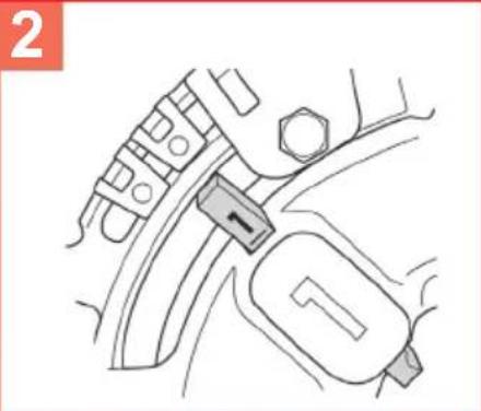
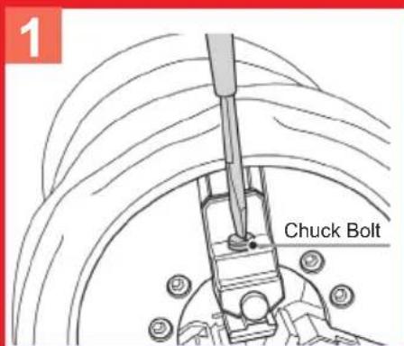
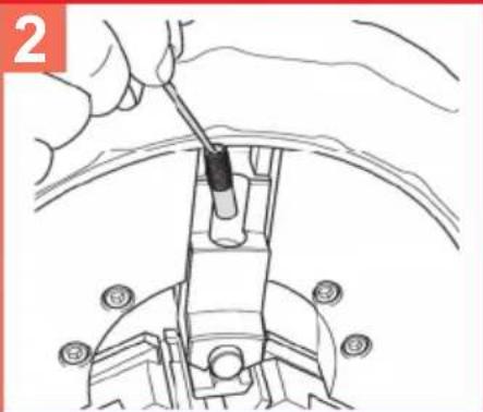
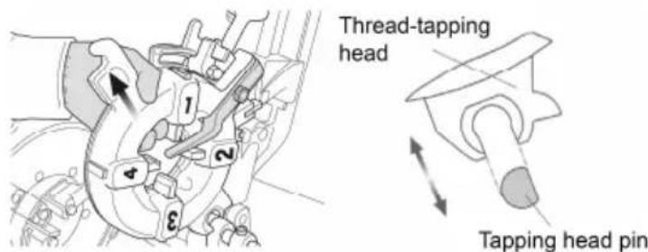
6.4 Removing and installing the dies (E)

Wear gloves in order to prevent cut injuries to the hands caused by the dies!
Removal:
→ Pull the parking lever into the "A" position.
→ Open the selector pin (silver colour) at the selector block.
→ Lift out the thread-tapping head and pull the thread jaws no. 1 to 4 down.
Installation:
→ Pull the parking lever in the "A" direction.
→ Open the selector pin (silver colour) at the selector block.
→ Insert the thread jaws with the same number as on the respective thread-tapping head and make sure it engages audibly.
→ Slide cam plate toward C until a click sound is heard from locking lever.
→ Ensure that the numbers on the thread-tapping head and on the thread jaws are on the same side.
Precise thread-tapping is only possible if the number on the slot of the thread-tapping head corresponds with the number on the thread jaw!
After changing the thread-tapping jaws, check that they are secure! After changing the thread-tapping head or replacing the thread-tapping jaws, check that they are locked securely in the tool carriage!
6.5 Installing and removing the thread-tapping head into and out of the bed carriage
→ Lift the thread-tapping head to half height.
→ Bring the thread-tapping head into the diagonal position and remove it.
→ Not until the thread-tapping head is in a parallel position to the flat side of the thread-tapping pin can it be removed from or installed in the machine.
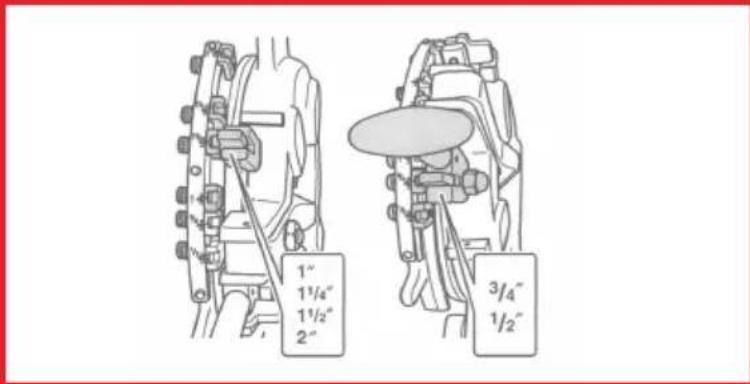
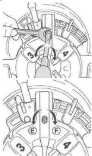
6.6 Changing the thread size (F)
→ Ensure that the thread-tapping head is on the tool carriage and that the thread jaws correspond to the thread size.
→ Insert the selector pin into the selector block with the necessary thread size.
→ The size is shown on the respective selector block.
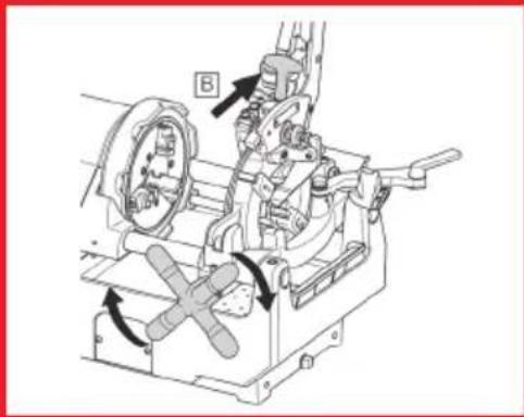
6.7 Tapping threads (G)
→ If there is a dangerous situation, press the safety pedal right down. This stops the machine.
→ To restart the machine, press the blue release button on the side of the safety pedal.
To guarantee precisely ground threads, follow the instructions below:
Use only raw material that is in perfect condition for tapping threads. If you use deformed and / or pipes cut off at an angle, it is not possible to tap threads that conform to the relevant standards!
Use the thread-tapping head and the corresponding thread-tapping jaws that match the thread size!
Secure the thread-tapping head correctly on the tool carriage.
Do not place the thread-tapping head directly and unprotected on the floor and handle it with care!
Ensure that the thread-tapping oil runs on the thread-tapping jaws!
→ Lower the thread-tapping head and insert the T handle, pressing in fully in the "B" direction until the thread-tapping jaws engage in the working position.
→ Switch on the machine with the pedal; turn the rotary handle clockwise so that the thread jaws press onto the workpiece.
→ Release the rotary handle when 2 to 3 thread turns are cut.
→ The thread-tapping jaws open automatically via a longitudinal stop lever when the thread has been fully cut.
→ Switch off the machine by taking your foot off the safety pedal.
6.8 Setting the thread length
The thread length was set by the manufacturer but can be changed if required.
→ Hold set pin with a slot screwdriver and loosen hex nut.
→ Turning set pin toward "E", makes shorter threads and turning toward "F" makes longer threads. The thread length will be changed about 2mm by half turn.
→ Hold set pin with a slot screwdriver not to turn it and tighten hex nut.
6.9 Setting the thread depth
→ Setzen Sie den Selektorpin in den nicht einzustellenden Set location plate to location block which is not for the size to be adjusted.
→ Loosen the screw and move location block to adjust the thread depth.
→ Sliding toward "G" makes deeper threads and sliding toward "H" makes shallower threads. The thread depth will change 1.5 to 2 mm threads by one scale.
With the aid of a measuring instrument, check the cut pipe for a tapered thread etc. and cor-rect the setting if necessary.
6.10 Removing the workpiece

The workpiece is damp and slippery from the thread-tapping oil. Carefully en-sure that it does not slip out of your hands and drop onto your feet when you remove it from the machine!
→ Turn the feeder hand wheel anti clockwise and move back the tool carriage.
→ Release the clamping chuck.
→ Release the centring chuck and pull out the workpiece.
6.11 Cleaning after use

Do not remove metal and plastic chips using compressed air! There is a risk of eye injuries and loss of eyesight! Do not pick up sharp-edged metal chips with your bare hands! Risk of injury! Wear protective gloves!
→ Remove chips from on and around the machine.
→ Use a wire brush to remove chips from and clean the clamping chuck, the thread-tapping jaws of the thread-tapping head and the internal deburrer.
→ Use a cloth to wipe thread-tapping oil splashes from the machine and the workplace.
7 Maintenance and inspection
The plug or electrical cord should be replaced only by the manufacturer of the electric tool or by its repair service.
All machines are subject to natural wear during use. They must be maintained from time to time and wear parts must be replaced. This work may only be carried out by an authorized ROTHENBERGER service station. This gives you a full warranty on the material and workmanship!

If the machine is being cleaned, maintained, inspected or repaired, it is essential to switch it off and to pull out the mains plug (de-energized operation)! Always avoid uncontrolled starting-up of the machine. Risk of injury and accidents!
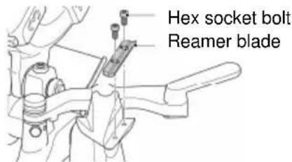
7.1 Changing the internal deburrer blade

Always wear protective gloves when replacing the blades! Risk of cuts and injury!
→ Lift up Pipe Cutter and Die-Head and pull Reamer frontward to set it.
→ Remove Bolts to fix Reamer Blade, and remove Reamer Blade.
→ Install a new Reamer Blade.
→ Fix Reamer Blade with Bolts.
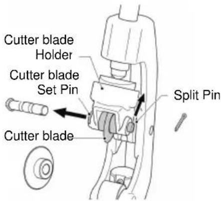
7.2 Changing the pipe cutter cutting wheel

Always wear protective gloves when replacing the blades! Risk of cuts and injury!
→ Lift up Pipe Cutter and lower Die-Head.
→ Straighten the bent Split Pin and pull it out upward.
→ While holding Cutter Blade, slightly push out Cutter Blade Set Pin from the Split Pin side and pull out from the opposite side.
→ Wipe off chips, dirt, oil, etc. on Pin and apply grease to the groove.
→ Put a new Cutter Blade into Cutter Blade Holder and insert Pin.
→ Insert a new Split Pin into Cutter Blade Set Pin, and bend the both tips.
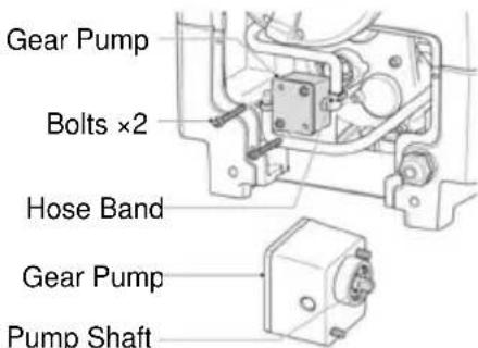
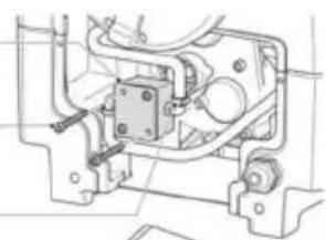
7.3 Replacement of Gear Pump

Oil in Gear Pump and Hoses overflows when remove them and it may stain the floor. Spread waste cloth around Gear Pump!
! Be careful not to put Power Code between Pump Cover and the machine body when installing Pump Cover. Power Cord may get damaged and it will cause current leakage!
→ Set an oil pan, remove Plug to drain Threading Oil.
→ Loosen four Bolts to fix Pump Cover and remove Pump Cover.
→ Loosen two Bolts to fix Gear Pump and remove Gear Pump.
→ Loosen Hose Bands and remove Hoses from Gear Pump. Be careful as oil overflows.
→ Install two Hoses to a new Gear Pump and tighten Hose Bands firmly.
→ Turn Pump Shaft to align it with the groove on the machine side, and install Gear Pump with removed Bolts.
→ Add Threading Oil and lower Die-Head.
→ Turn on the machine and check Theading Oil comes out from Die-Head.
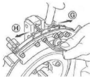
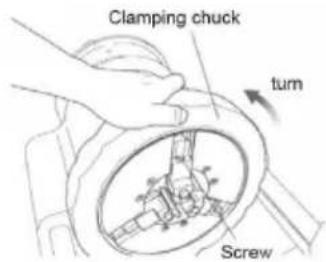
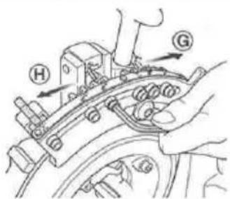
7.4 Changing the clamping jaw inserts (H)
→ Turn the clamping chuck and open it until a screwdriver fits inside.
→ Undo the screws that secure the clamping jaw inserts (H1).
→ Place a thin rod onto the upper edge of the spring and pull out the clamping chuck pin (H2).
→ Pull the clamping jaw insert forward (H3).
→ Insert a new clamping jaw insert and push it right to the back, replace the spring and the clamping chuck pin. Tighten the screw.
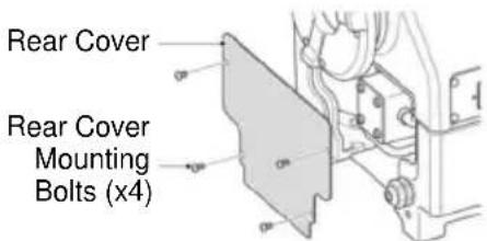
7.5 Replacement of Carbon Brush

Keep new Carbon Brush free from oil, dirt, chips, etc. Avoid the stain on gloves from attaching to Carbon Brush!
→ Remove Side Cover.
→ Remove Cap with a flat screwdriver and pull out Carbon Brush.
→ Insert a new Carbon Brush.
→ Tighten Cap and install Side Cover.
Side Cover
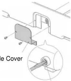
Cap
7.6 Daily inspection

Attention! Before starting the lubrication-works the power plug has to be taken out of the power source!
→ Check the mains plug, mains cable and extension cable to ensure they are undamaged.
→ Correctly filled oil trough.
→ Clean the oil tank if there are impurities in it.
→ Inspect the dies, pipe cutter and internal deburrer for any wear and replace parts if there is wear.
→ Clean the clamping jaws with a wire brush if they are dirty.
→ Check that the dowel screws are secure. Tighten if necessary.
→ Remove dirt and chips from the machine regularly.
→ Apply anti-rust grease if the machine is not going to be used for an extended period.
→ The rear spindle support has to be lubricated periodically. The lubrication is only allowed for persons which have been supervised in electrical safety issues!
8 Troubleshooting
| Symptom Possible Reason | Solution | |
| Does not start even turned on the machine | Power Cord is unplugged Plug in Power Cord | |
| Carbon Brush is worn out Replace Carbon Brush | ||
| Low voltage Set to the specified voltage | ||
| Motor failure Request repair | ||
| Power Cord has been damaged or broken | Request repair | |
| Slow rotation Low voltage If the problem is not solved | even with the specified voltage, request repair | |
| No threading oil, little Threading | Oil in Tank is low Replenish | Threading Oil |
| Filter is clogged with chips Clean Filter in Tank | ||
| Gear Pump failure | Replace Gear Pump | |
| Discharge amount of Thread-ing Oil has not been adjusted | Adjust discharge amount of Threading Oil | |
| Die-Head is not installed correctly | Install correctly | |
| Cannot thread properly Thread | depth and length are not adjusted | Adjust Die-Head |
| Dies are worn out and/or chipped | Replace Dies | |
| Deterioration of Threading Oil | Replace Threading Oil | |
| Threading Oil is not glnuine Use | Use genuine Threading Oil | |
| Dies are not installed properly | Install correctly | |
| The movement of each part is bad | Chips and iron powder are attached | Remove chips and iron powder |
9 Accessories
You can find suitable accessories in the main catalog or at www.rothenberger.com
10 Customer service
The ROTHENBERGER service locations are available to help you (see listing in catalog or online) and replacement parts and service are also available through these same service locations. Order your accessories and spare parts from your specialist retailer or using RO SERVICE+ online: 📞 + 49 (0) 61 95/ 800 8200 📄 + 49 (0) 61 95/ 800 7491 ✉ service@rothenberger.com - www.rothenberger.com
11 Disposal
11.1 Metal, electrical and electronic parts
Components of the unit are recyclable material and should be put to recycling. For this purpose registered and certified recycling companies are available. For an environmental friendly disposal of the non-recyclable parts (e.g. electronic waste) please contact your local waste disposal authority.
For EU countries only:

Do not dispose of electric tools with domestic waste. In accordance with European Directive 2012/19/EC on waste electrical and electronic equipment and its implementation as national law, electric tools that are no longer serviceable must be collected separately and utilised for environmentally compatible recycling.
11.2 Oils and lubricants
Only specialist companies are authorised to dispose of old oils.
Old oils and contaminated oils must be stored and disposed of in sealed, oil-resistant containers (metal drums).
Defective electrical appliances and machines that cannot be repaired must be opened and cleaned to remove the remaining oil.
Oil troughs must be cleaned so that there are no traces of oil. No oils (even very small amounts) may be allowed to enter the ground!
Capacité de coupe .... BSPT R 1/4" ... 2"(60.5mm), NPT 1/4" ... 2" (60.5mm),
Filetage de boulons 3/8" ... 2" (60.5mm)
Retirer le volant (I1)
service@rothenberger.com - www.rothenberger.com
Capacidad de corte .... BSPT R 1/4" ... 2"(60.5mm), NPT 1/4" ... 2" (60.5mm), Rosca de tornillo 3/8" ... 2" (60.5mm)
Material de corte ...... Acero, acero inoxidable
natural_image
Technical line drawing of a mechanical assembly with no visible text or symbolsTornillo de purga de aceite
natural_image
Mechanical assembly diagram showing internal components and mounting brackets (no text or labels)service@rothenberger.com - www.rothenberger.com
11 Eliminación
natural_image
Technical line drawing of a mechanical device with no visible text or symbolsSnijcapaciteit .... BSPT R 1/4" ... 2"(60.5mm), NPT 1/4" ... 2" (60.5mm),
Schroefdraad 3/8" ... 2" (60.5mm)
natural_image
Technical line drawing of a mechanical assembly with no visible text or symbolsolieaftapplug
5 Transport en opslag (I)
Capacidade de corte .... BSPT R 1/4" ... 2"(60.5mm), NPT 1/4" ... 2" (60.5mm),
Rosca de parafuso 3/8" ... 2" (60.5mm)
natural_image
Technical line drawing of a mechanical assembly with no visible text or symbolsSkærekapacitet .... BSPT R 1/4" ... 2"(60.5mm), NPT 1/4" ... 2" (60.5mm),
Bolt gevind 3/8" ... 2" (60.5mm)
Skæremateriale ...... Stål, rustfrit stål

Skärkapacitet .... BSPT R 1/4" ... 2"(60.5mm), NPT 1/4" ... 2" (60.5mm),
Skruvgängor 3/8" ... 2" (60.5mm)
Skärmaterial ...... Stål, rostfritt stål
Hastighet under tomgång ...... 38min ^1 (rpm)
Enfas-universalismotor 1150W
Frekvens 50/60 Hz
Dimensioner (l x b x h) 570 × 435 × 360mm
7.6 Daglig översyn

Kutteytelse .... BSPT R 1/4" ... 2"(60.5mm), NPT 1/4" ... 2" (60.5mm),
Ved hjelp av måleinstrumentet, skal du kontrollere det kuttede røret for en gjenge, og korriger innstillingen hvis nødvendig.
Leikkauskapasiteetti .... BSPT R 1/4" ... 2"(60.5mm), NPT 1/4" ... 2" (60.5mm),
Pultin kierre 3/8" ... 2" (60.5mm)
natural_image
Technical line drawing of a mechanical assembly with no visible text or symbolsÖljynpoistoruuvi
service@rothenberger.com - www.rothenberger.com
11 Kierrätys
natural_image
Technical line drawing of a mechanical assembly with no visible text or symbolsŘezná kapacita .... BSPT R 1/4" ... 2"(60.5mm), NPT 1/4" ... 2" (60.5mm), Závit šroubu 3/8" ... 2" (60.5mm)
natural_image
Technical line drawing of a mechanical assembly with no visible text or symbolsservice@rothenberger.com - www.rothenberger.com
11 Likvidace
Kesme kapasitesi.... BSPT R 1/4" ... 2"(60.5mm), NPT 1/4" ... 2" (60.5mm),
Vágási kapacitás.... BSPT R 1/4" ... 2"(60.5mm), NPT 1/4" ... 2" (60.5mm), Csavarmenet 3/8" ... 2" (60.5mm)
service@rothenberger.com - www.rothenberger.com
11 Ártalmatlanítás
natural_image
Technical line drawing of a mechanical assembly with no visible text or symbolsÖli väljalaskepolt
6.9 Keerme sügavuse seadistamine
Pjovimo pajègumas .... BSPT R 1/4" ... 2"(60.5mm), NPT 1/4" ... 2" (60.5mm),
Varžto sriegis 3/8" ... 2" (60.5mm)
natural_image
Technical line drawing of a mechanical assembly with no visible text or symbols6.9 Sriegio gylio nustatymas
natural_image
Technical line drawing of a mechanical assembly with no visible text or symbolsŽarna
Krumplia-
ratinis siurblys
Siurblio
velenas
natural_image
Technical line drawing of a mechanical assembly with no visible text or symbolsnatural_image
Technical diagram of a mechanical assembly with labeled components (no readable text or symbols)Zobrata sūknis
2 skrūves
Caurule
Zobrata sūknis
Sūkna
vārpsta
natural_image
Technical line drawing of a mechanical assembly with no visible text or symbols
7.4 letverspailu ieliktnu nomainišana
(H)
natural_image
Technical line drawing of a mechanical device with no visible text or symbolsD-65779 Kelkheim / Germany
Telefon +49 6195 / 800 - 0
Telefax +49 6195 / 800 - 3500
info@rothenberger.com

- OverviewA
- B Clamping
- C Cutting
- D Reaming
- Intro
- EU-DECLARATION OF CONFORMITY
- DECLARATION EU DE CONFORMITÉ
- Thomas Bamberger
- i. V. Maximilian Gottschalk
- Inhalt Seite
- Technical Data 21
- Function of the Unit 21
- Preparations for operation....22
- Carrying and Storage (I) 24
- Operation of the threading machine 24
- Maintenance and inspection....27
- Troubleshooting....29
- Accessories....30
- Customer service....30
- Disposal....30
- Markings in this document:
- Markings in this document!
- Caution!
- Call for action
- Safety Notes
- Intended use
- General safety instructions
- Service and maintenance:
- Working safely:
- Special safety instructions
- Technical Data
- Function of the Unit
- Overview (A)
- Functional description
- Preparations for operation
- Transporting the threading machine
- Setting up the machine
- Electrical connection
- The thread cutting oil
- ATTENTION PERSONS WITH ALLERGIES!
- Checking the thread cutting oil
- Setting the supplied thread cutting oil quantity
- Draining off the oil
- Carrying and Storage (I)
- Removing Rack Handle (1)
- Removing Reamer (2)
- Removing Splashproof Plate (3)
- Operation of the threading machine
- Clamping the workpieces (B)
- Cutting the workpiece with the pipe cutter (C)
- Reaming the workpieces (D)
- Removing and installing the dies (E)
- Removal:
- Installation:
- Installing and removing the thread-tapping head into and out of the bed carriage
- Changing the thread size (F)
- Tapping threads (G)
- Setting the thread length
- Setting the thread depth
- Removing the workpiece
- Cleaning after use
- Maintenance and inspection
- Changing the internal deburrer blade
- Changing the pipe cutter cutting wheel
- Replacement of Gear Pump
- Changing the clamping jaw inserts (H)
- Replacement of Carbon Brush
- Daily inspection
- Troubleshooting
- Accessories
- Customer service
- Disposal
- Metal, electrical and electronic parts
- For EU countries only:
- Oils and lubricants
- Retirer le volant (I1)
- Eliminación
- Transport en opslag (I)
- Daglig översyn
- Kierrätys
- Likvidace
- Ártalmatlanítás
- Keerme sügavuse seadistamine
- Sriegio gylio nustatymas
- letverspailu ieliktnu nomainišana
Brand : ROTHENBERGER
Model : SUPERTRONIC 2SE
Category : Machine tool