STE 18-3 130 - Electric grinder Flex - Free user manual and instructions
Find the device manual for free STE 18-3 130 Flex in PDF.

User questions about STE 18-3 130 Flex
0 question about this device. Answer the ones you know or ask your own.
Ask a new question about this device
Download the instructions for your Electric grinder in PDF format for free! Find your manual STE 18-3 130 - Flex and take your electronic device back in hand. On this page are published all the documents necessary for the use of your device. STE 18-3 130 by Flex.
USER MANUAL STE 18-3 130 Flex
natural_image
Technical line drawing of a mechanical power tool with mounting bracket and base mount (no text or symbols)

natural_image
Line drawing of hands operating a mechanical tool on a workbench (no text or symbols)- Gerät einschalten.
Symbols used in this manual ..... 14
Symbols on the product ..... 14
Important safety information ..... 14
Noise and vibration 17
Technical specifications 18
Overview 19
Instructions for use 20
Operating instructions ..... 21
Maintenance and care 22
Disposal information 22
CE Declaration of Conformity. . . . . . . . 22
Exemption from liability 22
Symbols used in this manual

WARNING!
Denotes impending danger.
Non-observance of this warning may result in death or extremely severe injuries.

CAUTION!
Denotes a possibly dangerous situation.
Non-observance of this warning may result in slight injury or damage to property.

NOTE
Denotes application tips and important information.
Symbols on the product

Before switching on the power tool, read the operating manual!
Wear goggles!

Always operate with two hands!

Disposal information for the old machine (see page 22)!
Protection class II


CE marking
For your safety

WARNING!
Before using the power tool, please read and follow:
– these operating instructions,
- the "General safety instructions" on the handling of power tools in the enclosed booklet (leaflet-no.: 315915),
– the currently valid site rules and the regulations for the prevention of accidents.
This power tool is state of the art and has been constructed in accordance with the acknowledged safety regulations.
Nevertheless, when in use, the power tool may be a danger to life and limb of the user or a third party, or the power tool or other property may be damaged. The power tool may be operated only if it is
- as intended,
- in perfect working order.
Faults which impair safety must be repaired immediately.
Intended use
Bush hammering machine STE 18-3 130 is designed
– for commercial use in industry and trade,
– for roughening and milling stone surfaces with tools which are offered by the manufacturer for this power tool,
– for use on staircases and surfaces.
It is not permitted to use cutting-off wheels, roughing wheels, fan-like grinding wheels or wire brushes.
When using the STE 18-3 130 stock machine, a class M dust extractor must be connected.
Safety instructions for all operations
Safety warnings common for grinding

WARNING!
Read all safety instructions and other instructions. Failure to observe the safety instructions and other instructions may result in an electric shock, fire and/or serious injuries. Keep all safety instructions and other instructions in a safe place for the future.
■ This power tool is intended to function as a sander. Read all safety warnings, instructions, illustrations and specifications provided with this power tool. Failure to follow all instructions listed below may result in electric shock, fire and/or serious injury.
■ Operations such as sanding, wire brushing, polishing, hole cutting or cutting-off are not to be performed with this power tool. Operations for which the power tool was not designed may create a hazard and cause personal injury.
■ Do not convert this power tool to operate in a way which is not specifically designed and specified by the tool manufacturer. Such a conversion may result in a loss of control and cause serious personal injury.
- Do not use accessories which are not specifically designed and specified by the tool manufacturer. Just because the accessory can be attached to your power tool, it does not assure safe operation.
■ The rated speed of the accessory must be at least equal to the maximum speed marked on the power tool. Accessories running faster than their rated speed can break and fly apart.
■ The outside diameter and the thickness of your accessory must be within the capacity rating of your power tool. Incorrectly measured insertion tools cannot be adequately shielded or controlled.
■ The dimensions of the accessory mounting must fit the dimensions of the mounting hardware of the power tool. Accessories that do not match the mounting hardware of the power tool will run out of balance, vibrate excessively and may cause loss of control.
■ Do not use a damaged accessory. Before use, always check insertion tools for splinters and cracks, sanding pad for cracks, wear and severe abrasion. If power tool or accessory is dropped, inspect for damage or install an undamaged accessory. After inspecting and installing an accessory, position yourself and bystanders away from the plane of the rotating accessory and run the power tool at maximum no-load speed for one minute. Damaged accessories will normally break apart during this test time.
■ Wear personal protective equipment. Depending on application, use face shield, safety goggles or safety glasses. If appropriate, wear a dust mask, hearing protection, protective gloves and/or a special apron which protect you from small sanding and material particles. The eye protection must be capable of stopping flying debris generated by various operations. The dust mask or respirator must be capable of filtrating particles generated by your operation. Prolonged exposure to high intensity noise may cause hearing loss.
- Keep bystanders a safe distance away from work area. Anyone entering the work area must wear personal protective equipment. Fragments of workpiece or of a broken accessory may fly away and cause injury beyond immediate area of operation.
- Hold power tool by insulated gripping surfaces only, when performing an operation where the cutting accessory may contact hidden wiring or its own cord. Cutting accessory contacting a “live” wire may make exposed metal parts of the power tool “live” and shock the operator.
■ Position the cord clear of the spinning accessory. If you lose control, the cord may be cut or snagged and your hand or arm may be pulled into the spinning accessory.
■ Never lay the power tool down until the accessory has come to a complete stop. The spinning accessory may grab the surface and pull the power tool out of your control.
■ Do not run the power tool while carrying it at your side. Accidental contact with the spinning accessory could snag your clothing, pulling the accessory into your body.
■ Regularly clean the power tool's air vents. The motor's fan will draw the dust inside the housing and excessive accumulation of powdered metal may cause electrical hazards.
■ Do not operate the power tool near flammable materials. Sparks could ignite these materials.
■ Do not use accessories that require liquid coolants. Using water or other liquid coolants may result in electrocution or shock.
Further safety instructions for all operations
Kickback and Related Warnings Kickback is the sudden reaction to a pinched or snagged rotating insertion tool, such as a sanding disc, sanding pad, wire brush, etc. Pinching or snagging may cause a rotating insertion tool to stop abruptly. For example, if an abrasive wheel is snagged or pinched by the workpiece, the edge of the wheel that is entering into the pinch point can dig into the surface of the material causing the wheel to climb out or kick out.
The wheel may either jump toward or away from the operator, depending on direction of the wheel's movement at the point of pinching. Abrasive wheels may also break under these conditions.
Kickback is the result of power tool misuse and/or incorrect operating procedures or conditions and can be avoided by taking proper precautions as given below.
- Maintain a firm grip on the power tool and position your body and arm to allow you to resist kickback forces. Always use auxiliary handle, if provided, for maximum control over kick-back or torque reaction during start-up.
The operator can control torque reactions or kickback forces, if proper precautions are taken.
■ Never place your hand near the rotating accessory. Accessory may kickback over your hand.
■ Do not position your body in the area where power tool will move if kickback occurs. Kickback propels the electric power tool in the direction opposite to the movement of the sanding disc at the point of pinching.
■ Use special care when working corners, sharp edges etc. Avoid bouncing and snagging the accessory. Corners, sharp edges or bouncing have a tendency to snag the rotating accessory and cause loss of control or kickback. This causes a loss of control or kickback.
■ Do not attach a saw chain woodcarving blade or toothed saw blade. Such blades create frequent kickback and loss of control.
Additional safety instructions for grinding and cutting-off operations
Safety warnings specific for grinding and cutting-off operations
■ Use only wheel types that are specified for your power tool and the specific guard designed for the selected wheel. Wheels for which the power tool was not designed cannot be adequately guarded and are unsafe.
■ The grinding surface of center depressed wheels must be mounted below the plane of the guard lip. An improperly mounted wheel that projects through the plane of the guard lip cannot be adequately protected.
■ The guard must be securely attached to the power tool and positioned for maxi - mum safety, so the least amount of wheel is exposed towards the operator. The guard helps to protect the operator from broken wheel fragments, accidental contact with wheel and sparks that could ignite clothing.
- Wheels must be used only for specified applications. For example: do not grind with the side of cut-off wheelAbrasive cut-off wheels are intended for peripheral grinding, side forces applied to these wheels may cause them to shatter.
■ Always use undamaged wheel flanges that are of correct size and shape for your selected wheel. Proper wheel flanges support the wheel thus reducing the possibility of wheel breakage. Flanges for cut-off wheels may be different from grinding wheel flanges.
■ Do not use worn down wheels from larger power tools. A wheel intended for larger power tool is not suitable for the higher speed of a smaller tool and may burst.
■ When using dual purpose wheels always use the correct guard for the application being performed. Failure to use the correct guard may not provide the desired level of guarding, which could lead to serious injury.
Additional safety instructions
■ Use only extension cables permitted for outdoor use.
■ It is not recommended to sand lead paint. Lead paint should be removed by a specialist only.
■ Do not work on materials which release hazardous substances (e.g. asbestos). Take precautions if hazardous, combustible or explosive dust is likely to occur. Wear protective dust mask. Use dust extraction system.

DAMAGE TO PROPERTY!
The mains voltage and the voltage specifications on the rating plate must correspond.
Noise and vibration

NOTE
Values for the A-weighted sound pressure level and for the total vibration values can be found in the “Technical specifications” table.
The noise and vibration values have been determined in accordance with EN 62841.

WARNING!
The indicated measurements refer to new power tools. Daily use causes the noise and vibration values to change.

NOTE
The vibration emission level given in this information sheet has been measured in accordance with a standardised test given in EN 62841 and may be used to compare one tool with another. It may be used for a preliminary assessment of exposure. The declared vibration emission level represents the main applications of the tool.
However if the tool is used for different applications, with different accessories or poorly maintained, the vibration emission may differ. This may significantly increase the exposure level over the total working period.
For a precise estimation of the vibrationload the times should also be considered during which the power tool is switched off or even running, but not actually in use.
This may significantly decrease the exposure level over the total working period. Identify additional safety measures to protect the operator from the effects of vibration such as: maintain the tool and the accessories, keep the hands warm, organisation of work patterns.

CAUTION!
Wear ear protection at a sound pressure above 85 dB(A).
Technical specifications
| Product type | STE 18-3 130 | |
| Product Bush hammering machine | ||
| Mains voltage | V/Hz 220 | -240 / 50/60 |
| Protection class | ☐/II | |
| Power input | W 1750 | |
| Power output | W 1060 | |
| No load speed | r.p.m. | 1000-2800 |
| Tool holder | M14 | |
| Working width mm 55-130 | ||
| Weight according to “FLEX Procedure 01” | kg 7.2 | |
| A-weighted sound pressure level according to EN 62841 (see “Noise and vibration”): | ||
| Sound pressure level L_pA | dB(A) 92 | |
| Sound power level L_WA | dB(A) 100 | |
| Uncertainty K db 3.0 | ||
| Total vibration value accordance with EN 62841 (see „Noise and vibration“): | ||
| Emission value a_h when sanding concrete surfaces | m/s2 | 7.3 |
| Uncertainty K | m/s2 | 1.5 |
Overview
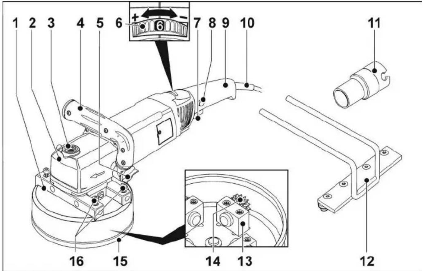
1 Milling head
2 Gear head
3 Spindle lock
Secures the spindle when the tool is changed.
4 Handle, adjustable
5 Rotary knob for adjusting the handle
6 Dial for preselecting the speed
7 S w i t c h
Switches the power tool on and off.
8 Starting lockout/Locking button
Prevents the power tool from starting up unintentionally and locks the switch (7) during continuous operation.
9 Stem handle
10 4.0 m mains connection cable with mains plug
11 Connector for dust extractor
12 Attachable stop
13 Bearing blocks
14 Carbide wheels
15 Rubber profile
16 Fastening screws for attachable stop
Instructions for use
Before switching on the power tool
Unpack power tool and accessories and check that no parts are missing or damaged.
Adjusting the handle
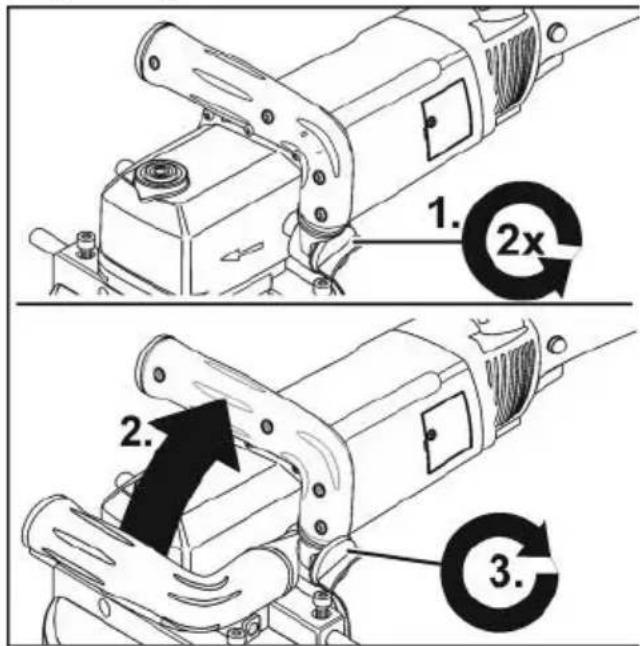
■ Loosen rotary knob for adjusting the handle by turning it approx. 2 revolutions anti-clockwise.
■ Place handle in the required position (15° notch).
Ensure that handle engages correctly!
■ Tighten rotary knob for adjusting the handle clockwise.

NOTE
If required, the handle can be moved to the other side of the electric power tool.
Connecting an extraction system

CAUTION!
The stock machine must be connected to a dust extractor during operation. The extraction system must be approved for stone dust. For the extraction of particularly harmful, carcinogenic, dry dust, a special extractor approved for such use must be used. In the event of a fault in the extractor, stop work immediately and switch off the power tool. Rectify the fault before bringing it back into operation.

NOTE
It is recommended to use a FLEX Class M dust extractor.
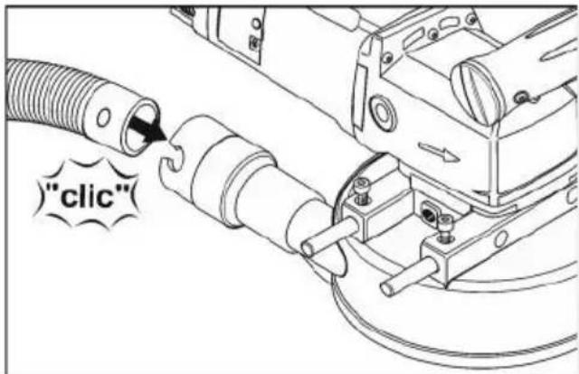
■ Attach extraction hose to the connector on the guard hood.
■ Attach power cord to the extraction hose using the enclosed cable holders (3x).
■ Connect extraction hose to the dust extraction system. Follow the operating instructions for the dust extraction system! Check the attachment! If required, use an appropriate adapter.

NOTE
If your dust extractor requires a special connection (i.e. a connection other than the 32 mm/36 mm standard connection which is included with the electric power tool), contact your dust extractor supplier to obtain the appropriate adapter.
Switching the electric power tool on and off
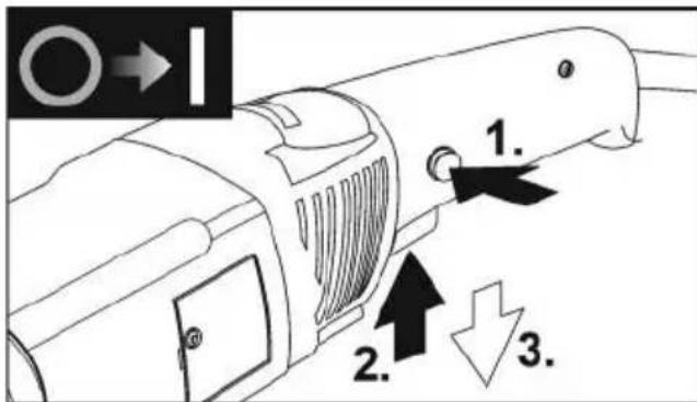
■ First press the starting lockout (1.). Then press and hold down the switch. Release switch interlock (2.).
■ To switch off, release the switch (3.).
Working with the power tool
Overload protection
If an extremely brief overload occurs, the overload protection prevents damage to the motor by automatically switching the device off.
For further information on the manufacturer's products go to www.flex-tools.com.
Preselecting the speed
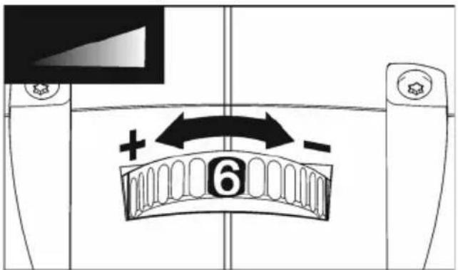
■ To set the operating speed, move the dial to the required value.
■ Gently press the switch to accelerate the power tool up to the preselected speed.
■ Always work in the lower speed area up to maximum setting 3.
i NOTE
If an overload or overheating occurs during continues operation, the power tool automatically reduces the speed until the power tool has cooled down adequately.
Setting working width
Different working widths can be set by attaching the bearing blocks with the carbide wheels in different positions.
■ Pull out the mains plug.
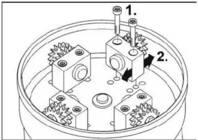
■ Loosen fastening screws on the bearing blocks (1.).
■ Attach bearing blocks in the required position (2.).
■ Align the carbide wheels inwards or outwards as required.
■ Retighten fastening screws on the bearing blocks.
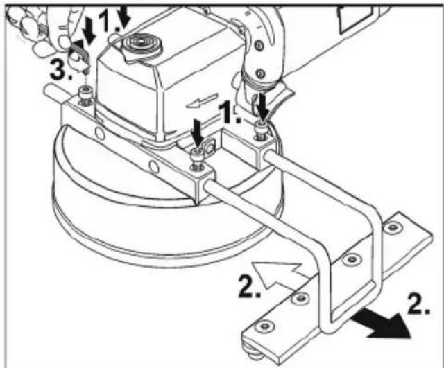
Setting attachable stop
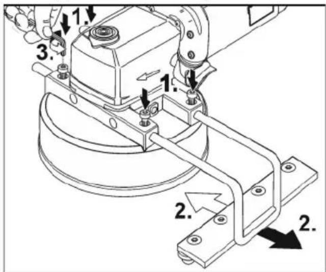
■ If required, loosen fastening screws (1.).
■ Push in the attachable stop sideways and set to the required working width (2).
■ Retighten fastening screws (3).
Operating instructions
WARNING!
The milling head must not come into contact with sharp projecting objects. Danger of kick-back! Damage to milling head. If the milling head is damaged or severely worn, it must be replaced.
CAUTION!
Hold the electric power tool with both hands!
- If required, set working width.
- If required, set side stop.
- Connect dust extraction system.
- Insert mains plug.
-
Conduct a test run to check that the tool is attached correctly.
Switch on the electric power tool (without locking the button) and leave it running for approx. 30 seconds. Check for imbalances and vibrations. -
Set required speed.
- Switch on dust extraction system.
- Hold the electric power tool with both hands.
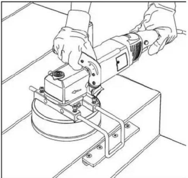
natural_image
Line drawing of hands operating a mechanical device with a circular base and lever mechanism (no text or symbols)- Switch on the device.
■ Do not leave the electric power tool running too long in one place.
■ Always perform smooth stroke movements.
■ Observe a minimum distance of 1 cm from the edge of the processed material.
Maintenance and care

WARNING!
Before performing any work on the electric power tool, pull out the mains plug.
Cleaning

WARNING!
Do not use water or liquid detergents.
■ Regularly blow out the housing interior and motor with dry compressed air.
■ Clean the protective hood with dry compressed air.
Repairs
Repairs and replacement of the supply cord may be carried out by an authorised customer service centre only.

NOTE
During the warranty period do not loosen the screws on the motor housing. Non-compliance will deem the guarantee obligations of the manufacturer null and void.
Spare parts and accessories
Further accessories, in particular insert tools, as well as exploded drawings and spare parts lists can be found on our homepage "http://www.flex-tools.com/" www.flex-tools.com or contact a sales partner.
Disposal information

WARNING!
Disable any power tools not in use by removing the mains connection cable.

EU countries only Do not throw electric power tools into the household waste!
In accordance with the European Directive 2012/19/EU on Waste Electrical and Electronic Equipment and transposition into national law used electric power tools must be collected separately and recycled in an environmentally friendly manner.

NOTE
Please ask your dealer about disposal options!

Declaration of Conformity
The Declarations of conformity are included in Annex 1 to this instruction manual.
Exemption from liability
The manufacturer and his representative are not liable for any damage and lost profit due to interruption in business caused by the product or by an unusable product. The manufacturer and his representative are not liable for any damage which was caused by improper use of the power tool or by use of the power tool with products from other manufacturers.
Table des matières
natural_image
Line drawing of hands operating a mechanical tool on a workbench (no text or symbols)- Allumer l'appareil.
natural_image
Line drawing of a hand operating a mechanical tool on a workbench (no text or symbols)natural_image
Line drawing of a hand operating a mechanical tool on a workbench (no text or symbols)- Encender el equipo.
natural_image
Line drawing of a hand operating a mechanical tool on a workbench (no text or symbols)■ Draai indien nodig de bevestigingsschroeven los (1.).
natural_image
Line drawing of a hand operating a power tool on a workbench (no text or symbols)natural_image
Line drawing of hands operating a mechanical device with a circular base and lever mechanism (no text or symbols)- Tænd maskinen.
natural_image
Line drawing of a hand operating a mechanical tool on a workbench (no text or symbols)- Slå på maskinen.
natural_image
Line drawing of a hand operating a mechanical tool on a workbench (no text or symbols)- Slå på verktyget.
natural_image
Line drawing of hands operating a mechanical tool on a workbench (no text or symbols)natural_image
Line drawing of hands operating a mechanical device with a circular base and lever mechanism (no text or symbols)natural_image
Line drawing of hands operating a mechanical device with a circular base and lever mechanism (no text or symbols)- Cihazı açın.
natural_image
Line drawing of a hand operating a power tool on a workbench (no text or symbols)- Włączyć urządzenie.
natural_image
Line drawing of hands operating a mechanical tool on a workbench (no text or symbols)natural_image
Line drawing of hands operating a mechanical device with a circular base and lever mechanism (no text or symbols)- Zapněte nářadí.
natural_image
Line drawing of hands operating a mechanical tool on a workbench (no text or symbols)- Zariadenie zapnite.
■ Otpustite pričvrsne vijke ležajeva (1.).
■ Ležajeve montirajte u željeni položaj (2.).
■ Kotačiće od tvrdog metala po potrebi usmjerite prema unutra ili van.
■ Ponovno pritegnite pričvrsne vijke ležajeva.
Postavljanje dodatne vodilice
■ Po potrebi otpustite pričvrsne vijke (1.).
■ Dodatnu vodilicu umetnite sa strane i postavite na željenu radnu širinu (2.).
■ Ponovno pritegnite pričvrsne vijke (3.).
Upute za rad
UPOZORENJE!
natural_image
Line drawing of a hand operating a mechanical tool on a workbench (no text or symbols)- Uključite alat.
Hrup in tresljaji 184
■ Po potrebi odvijte pritrdilne vijake (1.).
■ Nastavljivi prislon potisnite navznoter s strani in ga nastavite na želeno delovno širino (2.).
■ Znova privijte pritrdilne vijake (3.).
Navodila za delo
OPOZORILO!
natural_image
Line drawing of a hand operating a mechanical tool on a workbench (no text or symbols)- Vklopite orodje.
natural_image
Line drawing of hands operating a mechanical device with a circular base and lever mechanism (no text or symbols)- Porniți aparatul.
natural_image
Line drawing of hands operating a mechanical device on a workbench (no text or symbols)- Включете уреда.
natural_image
Line drawing of hands operating a mechanical device with a circular base and mounting bracket (no text or symbols)natural_image
Line drawing of hands operating a mechanical device with a tool, no text or symbols presentnatural_image
Line drawing of a hand operating a power tool on a workbench (no text or symbols)- ljunkite prietaisą.
natural_image
Line drawing of a hand operating a mechanical tool on a workbench (no text or symbols)- leslēdziet ierīci.
natural_image
Line drawing of hands operating a mechanical device with a circular base and lever mechanism (no text or symbols).9 قم بتشغيل الجهاز
Unit 8 Anglo Office Park
Lincoln Road
HP12 3RH, High Wycombe, Buckinghamshire
United Kingdom
Phone: +44 (0)1325 741 793
E-Mail: uk.sales@flex-tools.com