
MFKC 700 EB - Router FESTOOL - Free user manual and instructions
Find the device manual for free MFKC 700 EB FESTOOL in PDF.

| Product Type | Cordless Trimmer |
| Brand | Festool |
| Model | MFKC 700 EB |
| Motor Voltage | 18 V |
| Rotational Speed | 10 000 – 25 000 min⁻¹ |
| Max. No-Load Speed | 25 000 min⁻¹ |
| Tool Holder | 8 mm (optional: 6 mm, 1/4") |
| Max. Cutter Diameter | 32 mm |
| Max. Cutter Diameter with Edge Banding Milling Table | 26 mm |
| Dust Extraction Connector | 27 mm |
| Weight (without battery) | 1.8 kg |
| Compatible Batteries | Festool BP 18 series ≥ 4 Ah |
| Speed Control | Continuous via thumbwheel |
| Thermal Fuse | Yes, automatic shutdown in case of overheating |
| Anti-Restart Protection | Yes, after power interruption |
| Intended Use | Trimming and profiling of wood, plastic and similar materials |
| Sound Pressure Level | LPA = 82 dB(A) |
| Sound Power Level | LWA = 90 dB(A) |
| Vibration Emission (typical value) | < 2.5 m/s², uncertainty K = 1.5 m/s² |
| Materials | Wood, plastics |
| Maintenance | Clean cooling vents regularly; use original Festool spare parts |
| Included Accessories | Milling table, side stop, fork wrench (size 19) |
| Warranty | Refer to Festool terms |
Frequently Asked Questions - MFKC 700 EB FESTOOL
User questions about MFKC 700 EB FESTOOL
0 question about this device. Answer the ones you know or ask your own.
Ask a new question about this device
Download the instructions for your Router in PDF format for free! Find your manual MFKC 700 EB - FESTOOL and take your electronic device back in hand. On this page are published all the documents necessary for the use of your device. MFKC 700 EB by FESTOOL.
USER MANUAL MFKC 700 EB FESTOOL
MFKC 700 EB MFKC 700 KA EB

natural_image
Two black and white precision cutlamps with green buttons and labels, displayed against a white background (no visible text or symbols on the devices themselves)

| de Originalbetriebsanleitung 10 | |
| en Original instructions 14 | |
| fr Notice d’utilisation d’origine 18 | |
| es Manual de instrucciones original 22 | |
| bg Оригинална инструкция за експлоатация 27 | |
| cs Původní návod k obsluze 31 | |
| da Original brugsanvisning 35 | |
| el ПрWTÓTUNO OBNYIOW XPNONç 39 | |
| et Originaalkasutusjuhend 43 | |
| fi Alkuperäiset käyttöohjeet 47 | |
| hr Originalne upute za uporabu 51 | |
| hu Eredeti használati utasítás | 55 |
| it Istruzioni d’esercizio originali | 59 |
| lt | Originali naudojimo instrukcija | 63 |
| lv | Originālā lietošanas pamācība | 68 |
| nb | Original bruksanvisning 72 | |
| nl | Originele gebruiksaanwijzing | 76 |
| pl | Oryginalna instrukcja obstugi | 80 |
| pt | Manual de instruções original | 84 |
| ro | Manualul de utilizare original | 88 |
| sk | Originálny návod na obsluhu | 93 |
| sl | Originalna navodila za uporabo | 97 |
| sv | Originalbruksanvisning | 101 |
1A
MFKC 700 EB
1B
MFKC 700 KA EB
2A
2B

3
5
MFKC 700 EB
natural_image
Technical line drawing of a mechanical component with no visible text or symbols6
MFKC 700 KA EB
natural_image
Technical line drawing of a mechanical component with no visible text or symbols7
MFKC 700 EB
MFKC 700 KA EB
8
natural_image
Line drawing of a microscope with adjustment knobs and base mount (no text or labels)MFKC 700 EB
natural_image
Technical illustration of a mechanical assembly with a plus sign and a cross symbol (no text or labels)9
MFKC 700 KA EB
natural_image
Technical line drawings of mechanical components including a cylindrical shaft, a zoomed-in motor, and a multi-joint assembly (no text or symbols)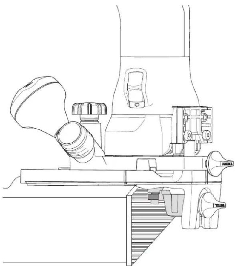
natural_image
Technical line drawing of a mechanical assembly with no visible text or symbols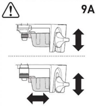
10
MFKC 700 KA EB
natural_image
Technical line drawings of mechanical components: a cylindrical part, a mechanical housing with crosshair marking, and a final mechanical assembly (no text or symbols)
natural_image
Technical line drawing of a mechanical device with no visible text or symbols
natural_image
Technical line drawing of a mechanical device with no visible text or symbolsen: EU Declaration of Conformity. We declare under sole responsibility that this product complies with all the relevant requirements in the following EU Directives, and following standards or normative documents were applied:
We as the manufacturer declare under our sole responsibility that the product(s) fulfill(s) all the relevant provisions of the following UK Regulations and are manufactured in accordance with the following designated standards:
S.I. 2008/1597 Supply of Machinery [Safety] Regulations 2008
S.I. 2017/1206 Radio Equipment Regulations 2017
S.I. 2016/1091 Electromagnetic Compatibility Regulations 2016
S.I. 2021/422 Restriction of the Use of Certain Hazardous Substances in Electrical and Electronic Equipment Regulations 2012
BS EN 62841-1:2015 + AC:2015 + A11:2022,
BS EN 62841-2-17:2017,
BS EN 55014-1:2017 + A11:2020,
BS 55014-2:1997 + A1:2001 + A2:2008 + AC:1997,
BS EN 300 328 V2.2.2,
BS EN 303 446-1 V1.2.1,
BS EN 301 489-1 V1.9.2,
BS EN 301 489-17 V3.2.4,
BS EN IEC 63000:2018
Head of Research & Development Products

Tim Weber
Head of Product Compliance
Deutsch
Inhaltsverzeichnis
1 Symbols....14
2 Safety warnings....14
3 Intended use....15
4 Technical data.... 15
5 Parts of the device....16
6 Battery pack.... 16
7 Settings....16
8 Working with the electric power tool....17
9 Service and maintenance....17
10 Accessories.... 17
11 Environment....17
12 General information....17
1 Symbols

Warning of general danger

Warning of electric shock

Read the operating manual and safety warnings.

Wear ear protection.

Wear a dust mask.

Wear protective gloves when changing tools.

Wear protective goggles.

Inserting the battery pack.

Remove the battery pack.

Do not dispose of it with domestic waste.

CE conformity marking

Tool contains a chip which stores data. See section 12.2

Tip or advice

UKCA marking: Confirms the conformity of the product with UK regulations.
2 Safety warnings
2.1 General power tool safety warnings

WARNING! Read all safety warnings, instructions, illustrations and specifications
provided with this power tool. Failure to follow all instructions listed below may result in electric shock, fire and/or serious injury.
Save all warnings and instructions for future reference. Follow the operating manual for the charger and the battery pack.
2.2 Machine-specific safety notices
- Use clamps or another practical way to secure and support the workpiece to a stable platform. Holding the work by your hand or against the body leaves it unstable and may lead to loss of control.
- Do not clamp tools with an unsuitable shank diameter in the clamping collet.
- Hold the power tool by the intended gripping surfaces [1-2]+[1-6] with both hands to ensure safe guidance.
- Only operate the power tool with a properly installed guide table.
- Only fit the routing tools offered by Festool for this power tool. The use of other routing tools is prohibited due to the increased risk of injury.
- Only use routing tools that meet standard EN 847-1. All Festool routing tools meet these requirements.
- The maximum rotational speed specified on the routing tool must not be exceeded or the rotational speed range must be observed. Accessories that rotate faster than the permissible level can rupture.
- The clamping collet and locking nut must not show any signs of damage
- Ensure that the routing tool is securely seated and check that it runs smoothly.
- Wear suitable personal protective equipment: Ear protection, safety goggles, a dust mask for work that generates dust.
- Do not use power supply units to operate cordless power tools. Only use the intended battery packs. Do not use third-party chargers to charge the battery packs. The use of accessories not expressly authorised by the manufacturer can result in electric shocks and/or serious accidents.
2.3 Safety warnings for routing tools
General
- Proceed with extreme care when unpacking, packing and handling the tool (e.g. installing it in the machine). There is a risk of injury from extremely sharp cutting edges!
- When handling the tool, wearing safety gloves provides a more secure hold of the tool and further reduces the risk of injury.
- Observe the safety warnings for your machine.
- Comply with the safety regulations that apply in your country.
- WARNING! Do not use tools with visible cracks or blunt or damaged cutting edges.
Installation and mounting
- Tools must be clamped in such a way that they cannot come loose during operation.
- Insert the routing tool into the collet as far as possible or at least up to the mark on the router shank.
- When assembling the tool, it must be ensured that the clamping takes place in the routing machine's collet and that the edges do not come into contact with one another or the fixed clamps.
- Clamping or fixing nuts must be tightened using suitable keys, etc. and with the torque specified by the manufacturer.
- Do not lengthen the key or tighten by hitting with a hammer.
- The clamping surfaces must be cleaned to remove contamination, grease, oil and water.
- Clamping screws must be tightened according to the manufacturer's instructions.
Service and maintenance
- Always use original Festool spare parts.
- Repairs and sanding work may only be carried out by experts.
- The tool design must not be changed.
- For repairs and sanding work, see the additional instructions at www.festool.com.
- Deresinify and clean the tool regularly (cleaning agent with pH between 4.5 and 8).
- Blunt edges can be resharpened on the clamping surface to a minimum cutting edge thickness of 1 mm.
- Only transport the tool in suitable packaging – risk of injury!
2.4 Emission levels
The levels determined in accordance with EN 62841 are typically:
| Sound pressure level L | _PA = 82 dB(A) |
| Sound power level L | _WA = 90 dB(A) |
| Uncertainty K = 3.0 dB |


CAUTION
Noise emissions created while working with the power tool may damage your hearing.
▶ Always use ear protection.
Vibration emission level a_h (vector sum for three directions) and uncertainty K measured in accordance with EN 62841:
$$ a _ {h} < 2. 5 \mathrm{m} / \mathrm{s} ^ {2} $$
$$ K = 1. 5 \mathrm{m} / \mathrm{s} ^ {2} $$
The specified emission levels (vibration, noise)
- are used to compare machines.
- They are also used for making preliminary estimates regarding vibration and noise load during operation.
- They represent the primary applications of the power tool.

CAUTION
The emission values may deviate from the specified values. This is dependent on how the tool is used and the type of workpiece being machined.
- Assess the actual load during the entire operating cycle.
▶ Determine suitable safety measures depending on the actual load.
3 Intended use
The edge router is designed for flush trimming and profile routing wood, plastic and similar materials.
The user is liable for improper or non-intended use.
3.1 Routing tools
Type of feed
MAN (manual feed).
Speed
The maximum speed specified on the tool must not be exceeded and the speed range must be adhered to.
Materials
Wood, plastics. Observe the material information on the packaging.
Only qualified and experienced persons who are familiar with the tools are permitted to use them.
4 Technical data
| Cordless edge router MFKC 700 EB | |
| MFKC 700 KA EB | |
| Motor voltage 18V | --- |
| Speed 10000–25000 rpm | |
| Max. speed (no-load) 25000 rpm | |
| Compatible battery packs | Festool series BP 18 ≥ 4 Ah |
| Tool holder 8 mm | (optional: 6 mm, 1/4") |
| Cutter diameter, max. 32 mm | |
| Cutter diameter, max., with router table with edge veneer (accessory) | 26 mm |
| Dust extraction connection 27 mm | |
| Weight excl. battery pack 1.8 kg | |
4.1 Routing tools
For technical data, see imprint on the routing tool.
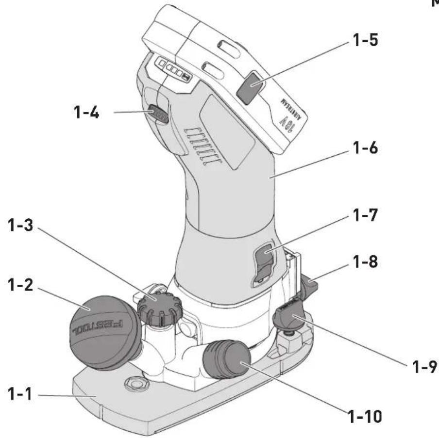
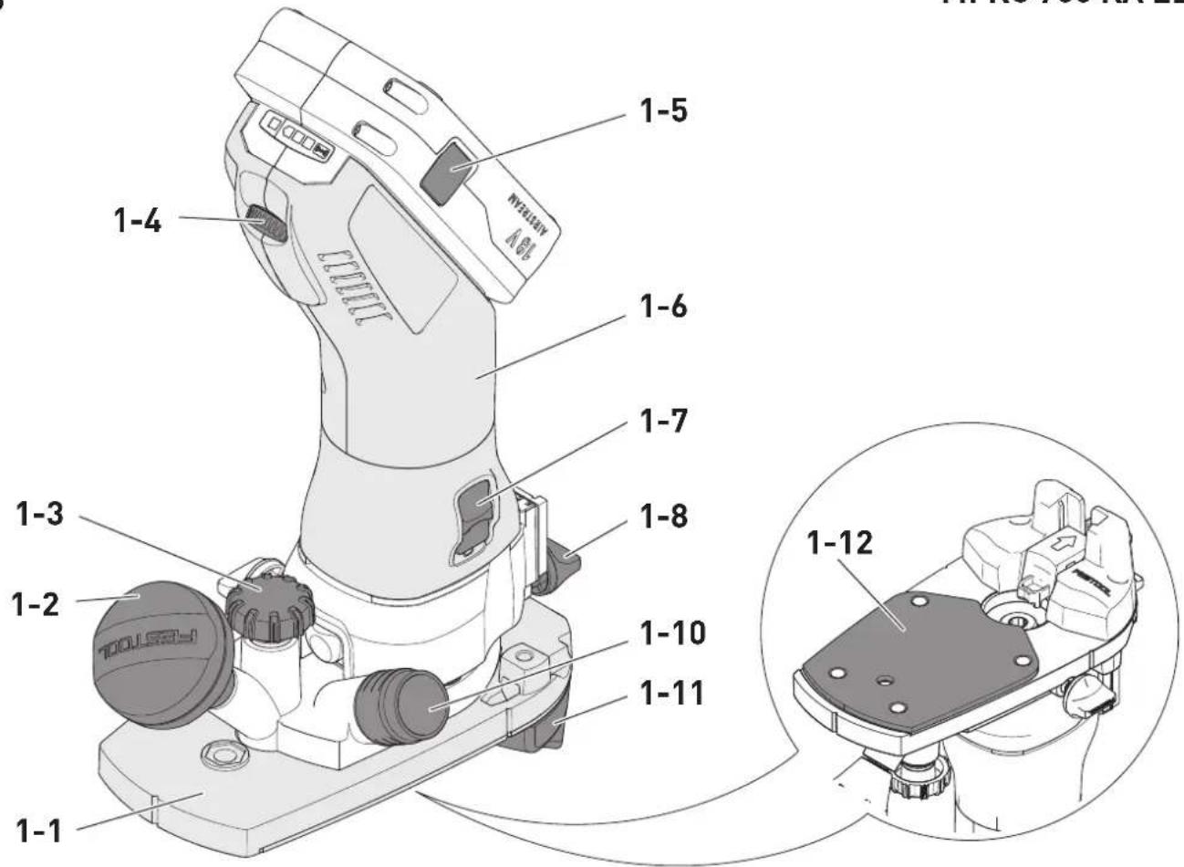
5 Parts of the device
[1-1] Router table *
[1-2] Gripping surface, routing depth locking mechanism
[1-3] Routing depth setting
[1-4] Speed control
[1-5] Button for releasing the battery pack
[1-6] Gripping surface
[1-7] On/off switch
[1-8] Routing depth locking mechanism
[1-9] Rotary knobs for attachment of a parallel side fence *
[1-10] Extractor connector
[1-11] Router stop *
[1-12] Rebated base runner *
The specified illustrations appear at the beginning of the Operating Instructions.
* Accessories shown or described are not always included in the scope of delivery.
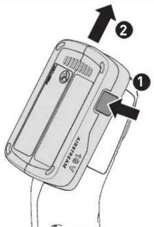
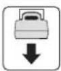
6 Battery pack
Before using the battery pack, check that the battery interface is clean. Any contamination of the battery interface may impair correct contact and lead to the contacts being damaged.
A faulty contact may result in the machine overheating or being damaged.
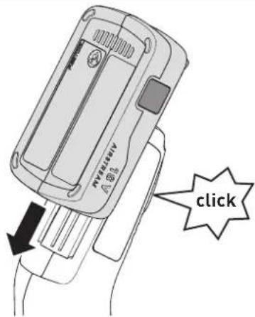
[2A]
Remove the battery pack.
[2B]
Insert the battery pack until it clicks into place.

Further information about the charger and battery pack can be found in the corresponding operating manual.
7 Settings

WARNING
Risk of injury
- Remove the battery pack from the power tool before performing any work on the power tool.
7.1 Electronics
Speed control
You can use the adjusting wheel [1-4] to continuously adjust the speed within the speed range (see Section Technical data). This enables you to optimise the speed to suit the respective material. Please also note the specifications on the tools.
Scorch or melt marks on the material can be prevented through reducing the speed.
Temperature cut-out
The power tool switches off if it becomes too hot. It can only be switched on again once the power tool has cooled sufficiently.
Restart protection
The built-in restart protection prevents the power tool from starting up again automatically if the power is disconnected during continuous use. To put the power tool back into operation, it must first be switched off and then on again.
7.2 Festool app\*
The power tool can be configured with the Festool app. To do this, the battery pack used must be a Bluetooth® battery pack.

The battery pack is connected via Bluetooth ^® , see the operating manual for the battery pack.
* Not available in all countries.
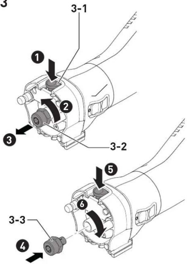
7.3 Replacing the collet [3]
Only suitable routing tools can be used with the supplied collets. Collets of 8 mm, 6 mm and 1/4" (6.35 mm) can be used.
▶ Push spindle lock [3-1].
▶ Unscrew the union nut [3-2] fully.
▶ Release spindle lock [3-1].
▶ Remove the union nut together with the collet [3-3] from the spindle. Never separate the union nut from the collet. They form one unit.
▶ Insert another collet with union nut into the spindle.
▶ Gently turn the union nut. Do not tighten the union nut if there is no routing tool inserted.
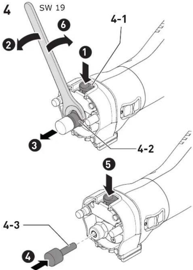
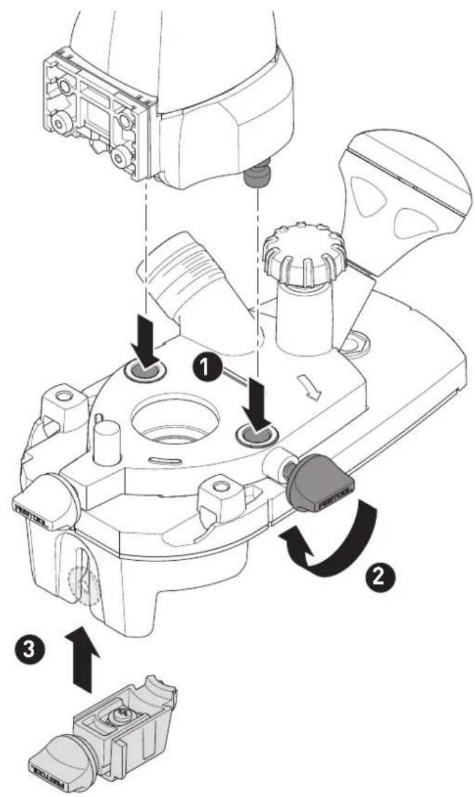
7.4 Changing the routing tool [4]
![FESTOOL MFKC 700 EB - Changing the routing tool [4] - 1](/content/2026/04/738353/images/d1ae7e3a25e667fb7c8ce2b37b101b8b0443e3631e55ccf7ba145f15e3e589ad.jpg)
![FESTOOL MFKC 700 EB - Changing the routing tool [4] - 2](/content/2026/04/738353/images/31840dc235993837bae958b1b25b5861d2c6a858d4abf14ee0cabd8a22319149.jpg)
CAUTION
Risk of injury from hot and sharp tool.
▶ Do not use any blunt or faulty tools.
▶ Wear protective gloves when handling a tool.
Remove the router table before changing the routing tool.
Removing the routing tool
▶ Push spindle lock [4-1].
▶ Slacken the union nut [4-2] using the open ended spanner (WAF 19) until the routing tool can be removed.
▶ Release spindle lock [4-1].
Inserting the routing tool
- Insert the routing tool [4-3] into the open collet as far as possible, at least up to the mark on the router shank.
▶ Push spindle lock [4-1].
▶ Tighten the union nut [4-2] using the open ended spanner (WAF 19).
▶ Release spindle lock [4-1].
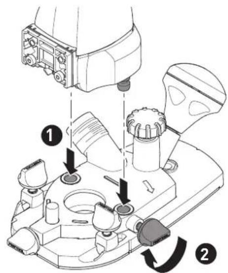
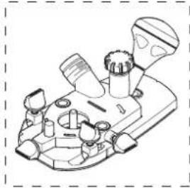
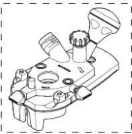
7.5 Fitting the router table
▶ MFKC 700 EB see figure [5]
▶ MFKC 700 KA EB see figure [6]
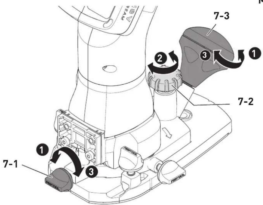
7.6 Setting the routing depth [7]
- Slacken the locking mechanisms for routing depth [7-3] and [7-1].
▶ Set the router table to the desired routing depth using the dial [7-2].
▶ Tighten the locking mechanisms for routing depth.
7.7 Dust extraction

WARNING
Heath hazard posed by dust
▶ Always work with an extractor.
▶ Comply with national regulations.
A Festool mobile dust extractor with an extraction hose diameter of 27 mm should be connected at the extractor connector [1-10].
CAUTION! A static charge may build up if no antistatic suction hose is used. The user may receive an electric shock and the power tool's electronics may be damaged.
8 Working with the electric power tool

When working on the machine, observe all of the safety warnings that are listed at the start as well as the following rules:
- Make sure that the router table is firmly tightened before routing.
- Always secure the workpiece in such a way that it cannot move during machining.
- Adjust the feed speed to the cutter diameter and the material. Work with a constant feed speed.
- Only guide the power tool towards the workpiece when it is switched on.
- Wait until the power tool has come to a complete halt before placing it down. The insertion tool can get caught and lead to a loss of control of the power tool.
- When routing, ensure that the power tool's feed direction is the same as the tool's cutting direction.
8.1 Switching on/off
The switch [1-7] serves as an on/off switch (I = ON, 0 = OFF).

Remove the protective film from the router table prior to commissioning.
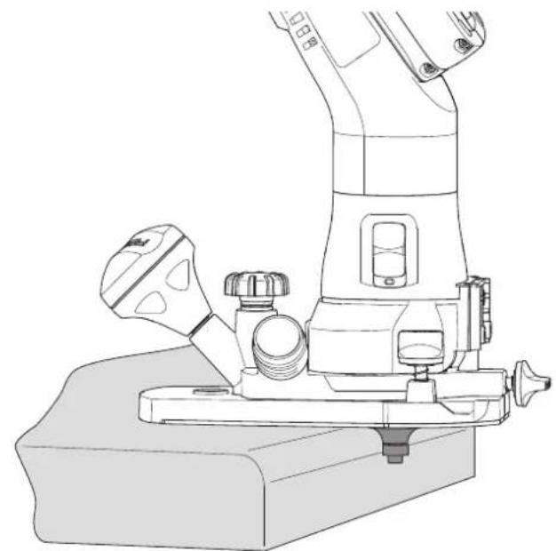
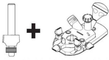
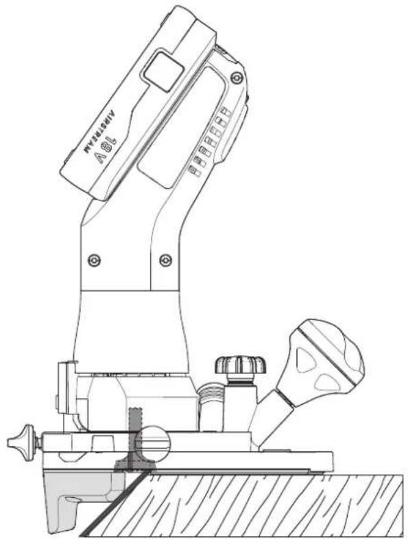
8.2 Routing edges MFKC 700 EB [8]
Insert routing tools with a ball bearing guide into the power tool.
Guide the power tool in such a way that the ball bearing guide rolls on the workpiece.
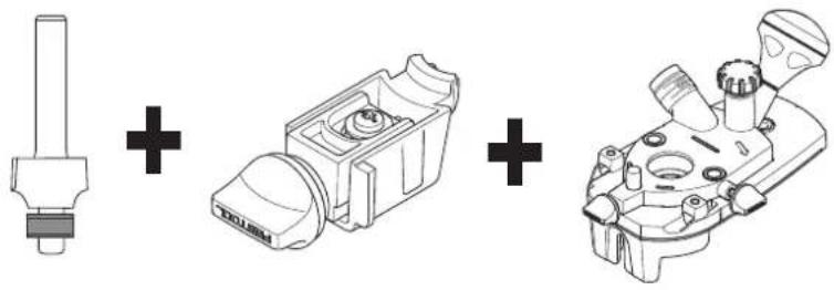
8.3 Routing edges MFKC 700 KA EB
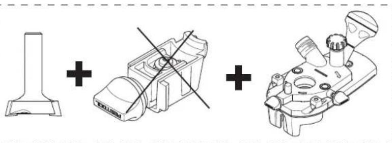
Routing with a ball bearing guide [9]
In order to work with routing tools with a ball bearing guide, insert the ball bearing brake into the edge router. Adjust the height of the ball bearing brake to the height of the ball bearing guide in two stages [9A].
Guide the power tool so that the ball bearing guide of the routing tool rolls between the brake and edging.
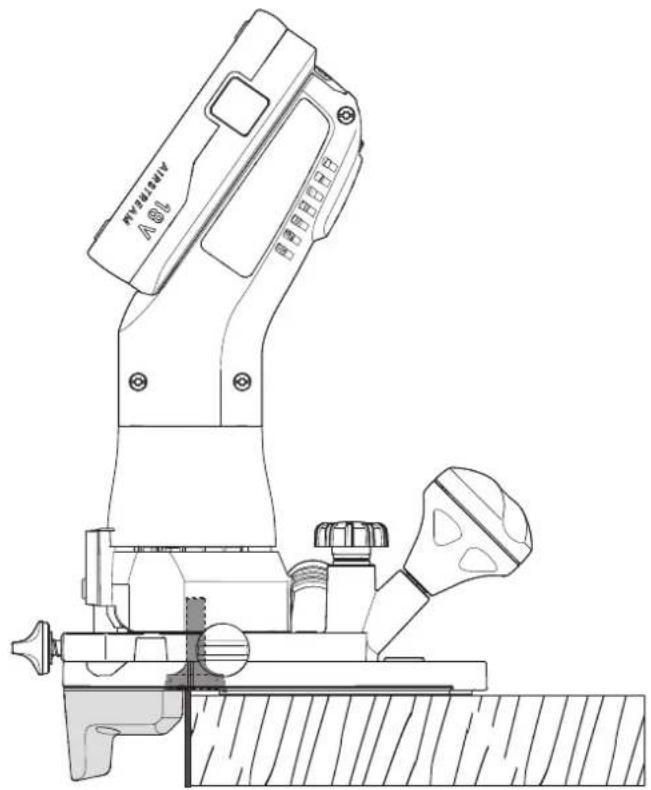
Routing with the plane cutter [10]
Do not use a ball bearing brake for working with plane cutters.
Guide the power tool in such a way that the stop of the router table is flush with the edging. This is also possible on oblique edges.
9 Service and maintenance

WARNING
Risk of injury, electric shock
▶ Always remove the battery pack from the power tool before performing any maintenance or service work.
▶ Have all maintenance and repair work that requires the motor housing to be opened carried out by an authorised service workshop.
Customer service and repairs must only be carried out by the manufacturer or service workshops. You must only use original Festool spare parts.
Further information: www.festool.co.uk/service
▶ Damaged safety devices and components must be repaired or replaced in a recognised specialist workshop, unless otherwise indicated in the operating instructions.
▶ To ensure constant air circulation, always keep the cooling air openings in the motor housing clean and free of blockages.
10 Accessories
You can find the PO numbers for accessories and tools under www.festool.co.uk.
11 Environment

Do not dispose of electrical devices, used batteries and battery packs in the household waste. Recycle devices, accessories and
packaging. Observe applicable national regulations.
Before disposing of used batteries, battery packs and lamps, separate them from the electrical device without destroying them. This means they can be recycled efficiently.
In accordance with the European Directive on waste electrical and electronic equipment and implementation in national law, used electrical devices must be collected separately and handed in for environmentally friendly recycling.
Information on the collection points can be viewed at www.festool.com/environment.
Information on critical materials: www.festool.co.uk/reach
12 General information
12.1 Licence information
Licence information on any open source licences used in the product can be found in the Festool app* at Information > Power tool open source licenses.
* Not available in all countries.
Imported into the UK by
Festool UK Ltd
1 Anglo Saxon Way
Bury St Edmunds
IP30 9XH
Great Britain
12.2 Information on data privacy
The power tool contains a chip which automatically stores machine and operating data. The data saved cannot be traced back directly to an individual.
The data can be read in a contactless manner using special devices and shall only be used by Festool for fault diagnosis, repair and warranty processing and for quality improvement or enhancement of the power tool. The data
shall not be used in any other way without the express consent of the customer.
12.3 Bluetooth®
The Bluetooth® word mark and the logos are registered trademarks of Bluetooth SIG, Inc.; they are used by TTS Tooltechnic Systems AG & Co. KG, and therefore by Festool, under licence.
Français
Sommaire
Incertitude K = 3,0 dB


ATTENTION
12.1 Informations relatives aux licences
Incertidumbre K = 3,0 dB

ATENCIÓN
▶ MFKC 700 EB vt joonist [5]
▶ MFKC 700 KA EB vt joonist [6]
7.6 Freesimissügavuse reguleerimine [7]
Usikkerhet K = 3,0 dB
![FESTOOL MFKC 700 EB - Freesimissügavuse reguleerimine [7] - 1](/content/2026/04/738353/images/97ad1585efe11fa32875c9cbfea81b114e80712b0042b55425c812b6dbdd633d.jpg)
FORSIKTIG
Negotovost K = 3,0 dB


PREVIDNO


- MFKC 700 EB MFKC 700 KA EB
- Tim Weber
- Deutsch
- Inhaltsverzeichnis
- Symbols
- Safety warnings
- General power tool safety warnings
- Machine-specific safety notices
- Safety warnings for routing tools
- General
- Installation and mounting
- Service and maintenance
- Emission levels
- CAUTION
- Noise emissions created while working with the power tool may damage your hearing.
- The emission values may deviate from the specified values. This is dependent on how the tool is used and the type of workpiece being machined.
- Intended use
- Routing tools
- Type of feed
- Speed
- Materials
- Routing tools
- Parts of the device
- Battery pack
- Settings
- WARNING
- Risk of injury
- Electronics
- Speed control
- Temperature cut-out
- Restart protection
- Festool app\*
- Replacing the collet [3]
- Changing the routing tool [4]
- Risk of injury from hot and sharp tool.
- Removing the routing tool
- Inserting the routing tool
- Fitting the router table
- Setting the routing depth [7]
- Dust extraction
- Heath hazard posed by dust
- Working with the electric power tool
- Switching on/off
- Routing edges MFKC 700 EB [8]
- Routing edges MFKC 700 KA EB
- Routing with a ball bearing guide [9]
- Routing with the plane cutter [10]
- Service and maintenance
- Risk of injury, electric shock
- Accessories
- Environment
- General information
- Licence information
- Imported into the UK by
- Information on data privacy
- Bluetooth®
- Français
- Sommaire
- ATTENTION
- Informations relatives aux licences
- ATENCIÓN
- Freesimissügavuse reguleerimine [7]
- FORSIKTIG
- PREVIDNO
Brand : FESTOOL
Model : MFKC 700 EB
Category : Router