BB-02 - Mechanic tool MSW - Free user manual and instructions
Find the device manual for free BB-02 MSW in PDF.

| Product type | Hydraulic brake bleeder |
| Brand | MSW |
| Model | BB-02 |
| Category | Mechanic tool |
| Dimensions (L x W x H) | 155 x 255 x 255 mm |
| Weight | 1.5 kg |
| Power supply | Compressed air (via air inlet) |
| Refill bottle capacity | 1 liter |
| Main functions | Hydraulic brake bleeding, air bubble removal, brake fluid filling |
| Supplied components | Air flow handle, fixing clamp, silicone hose (1 m), universal adapter, refill bottle, extraction reservoir |
| Maintenance | Clean after each use, check for leaks and blockages, rinse with clean water |
| Safety | Brake fluid is flammable and toxic: wear gloves and goggles, avoid contact with skin and eyes, keep away from ignition sources |
| Storage | Dry and clean place, temperature controlled, protected from shocks |
| Troubleshooting | If no fluid is drawn: check the shut-off valve and air handle. Leaks: tighten connections or replace parts. |
Frequently Asked Questions - BB-02 MSW
User questions about BB-02 MSW
0 question about this device. Answer the ones you know or ask your own.
Ask a new question about this device
Download the instructions for your Mechanic tool in PDF format for free! Find your manual BB-02 - MSW and take your electronic device back in hand. On this page are published all the documents necessary for the use of your device. BB-02 by MSW.
USER MANUAL BB-02 MSW
natural_image
Two spray sprayers with hoses and tubing, one white and one gold-colored, displayed against a plain background (no text or symbols visible)natural_image
Close-up of a mechanical assembly with a white plastic component mounted on a vehicle hood, showing wiring and components (no visible text or symbols)Abbildung 1
Abbildung 2
This User Manual has been translated using machine translation. We have made every effort to ensure the translation is accurate, but please note that automated translations are not perfect and are not meant to replace human translators. The official version of the User Manual is in English. Any differences between the translated version and the original English are not legally binding. If you have any questions about the accuracy of the translation, please refer to the English version, which is the official reference. More language versions are available upon request via info@expondo.com.
Technical data
| Parameter description | Parameter value |
| Product name | Brake bleeder |
| Model | MSW-BB-02 |
| Dimensions (Width x Length x Height) [mm] | 155x255x255 |
| Weight [kg] | 1.5 |
Product Overview

natural_image
Two spray sprayers with hoses and tubing, one blue and black, the other a brass and white (no visible text or symbols)The product is a tool used to remove air bubbles from the brake lines in a hydraulic braking system. Its primary function is to ensure proper brake fluid flow, eliminating air that can cause spongy or unresponsive brakes. It is typically used during brake fluid changes or maintenance, allowing technicians to ensure the brake system is fully pressurized and free from air, ensuring optimal braking performance.
The user is liable for any damage resulting from unintended use of the product.
Usage

WARNING
- Brake fluid is flammable – Keep away from sources of ignition, especially hot surfaces like exhaust pipes or manifolds.
-
Brake fluid damages paintwork – Immediately flush any spillages with clean water and dry off.
• Wear eye protection and minimize skin contact with brake fluid. -
If brake fluid enters eyes, immediately rinse with clean water and seek medical attention.
- If swallowed, seek medical advice immediately.
- Dispose of waste brake fluid responsibly and in accordance with local authority regulations.
Automatic Refill Bottle
natural_image
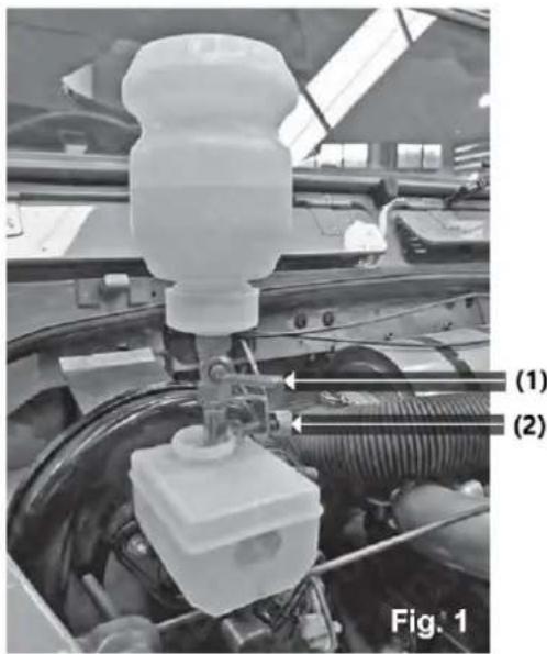
Close-up of a mechanical assembly with a white plastic component and labeled parts (1) and (2), no readable text or symbols beyond labels.Figure 1
- Fill the required amount of fluid into the refill bottle (maximum 1 liter).
- Refer to Figure 1: Ensure the brass shut-off valve (1) is in the horizontal (closed) position.
- Invert the refill bottle, then clamp (2) onto the brake or clutch master cylinder reservoir.
Components
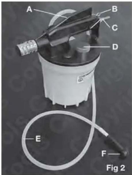
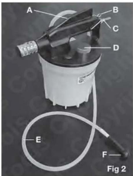
Figure 2
A- Air Flow Handle (ON/OFF)
B- Air Flow Handle Securing Clamp
C- Air Inlet
D- Extracting Tank Stopper
E- 1 Meter Silicone Hose
F- Universal Brake Nipple Adaptor
Operating steps

NOTE Refer to the manufacturer's documentation or workshop manual to determine the correct method and sequence for bleeding the brakes.
-
Ensure the brake nipples are clean and check that they are not seized. (Refer to Figure 2)
-
Connect the bleed pipe and adaptor (F) to the brake nipple to be bled.
-
Connect the air line to the air inlet (C).
-
Open the brass shut-off valve on the refill bottle (Figure 1).
-
Open the bleed nipple.
-
Press down the air flow handle (A) and secure it if necessary with the clamp (B).
-
Fluid should now be drawn into the bleeder extraction tank.
-
Pay careful attention to the fluid level in the refill bottle. If more brake fluid is needed to complete the brake bleed operation, close the brass shut-off valve before refilling the refill bottle.
-
When finished, remove the extraction tank stopper (D) and empty the used brake fluid. Dispose of it according to local authority guidelines.
-
Carefully clean both the extraction tank and refill bottle, and store them in a clean, dry location.
Storage
Proper storage is essential to maintaining the longevity of the brake bleeder:
-
Clean and Dry Storage: After cleaning, store the brake bleeder in a dry, clean location. Avoid leaving any residual brake fluid inside the components to prevent damage or corrosion.
-
Store in a Temperature-Controlled Environment: Keep the brake bleeder away from extreme temperatures. Store it in a place where temperatures do not exceed the product's recommended storage range.
-
Protect from Physical Damage: Store the tool in a safe place to avoid physical damage. Use protective covers if necessary to prevent damage to the components during storage.
-
Check Regularly for Damage: Before each use, inspect the brake bleeder for any signs of wear, cracks, or damage. Replace worn-out parts promptly to ensure safe operation.
Maintenance
To ensure the brake bleeder remains in optimal working condition, follow these maintenance guidelines:
1. Clean the Unit Regularly:
- After each use, thoroughly clean the brake bleeder, including the extraction tank and refill bottle. Use a cloth to wipe down all components, removing any residual brake fluid.
- Flush the system with clean water if necessary to remove any brake fluid residue.
2. Check for Leaks:
- Inspect all hoses, connectors, and valves for potential leaks. Tighten any loose connections and replace damaged components immediately to avoid fluid loss and ensure efficient operation.
3. Inspect the Air Flow System:
- Ensure the air inlet (C) and air flow handle (A) are functioning properly. Test the system with air pressure to confirm the flow is correct.
4. Check for Blockages:
- Periodically check that the fluid hose and all adapters are free from blockages that may affect the fluid flow during operation.
Troubleshooting
If you encounter any issues while using the brake bleeder, refer to the following troubleshooting steps:
1. No Fluid is Being Drawn into the Extraction Tank:
• Possible Cause: The brass shut-off valve (1) may be closed.
Solution: Ensure the shut-off valve is in the correct position (horizontal for closed). Open the valve and retry.
• Possible Cause: Air flow handle (A) is not engaged properly.
Solution: Press down the air flow handle and ensure it is secured with the clamp (B).
2. Brake Fluid Leaks:
• Possible Cause: Loose or damaged connections.
Solution: Check all hoses, connectors, and adaptors for proper sealing. Tighten connections or replace damaged parts.
3. Air in Brake Lines After Bleeding:
• Possible Cause: Incomplete fluid extraction or improper bleeding sequence.
Solution: Double-check the bleeding sequence as per the manufacturer's manual. Ensure the fluid level in the refill bottle is adequate during the process and that the bleed nipple is fully open.
4. Excessive Fluid Spillage:
• Possible Cause: Overfilling of the refill bottle.
Solution: Make sure not to exceed the 1-liter maximum fill capacity for the refill bottle.

natural_image
Two gas washing machines, one with a spray gun and blue cap, the other with a brass hose and coiled tubing (no visible text or symbols)natural_image
Close-up of a mechanical assembly with a white plastic component mounted on a vehicle head, showing wiring and components (no visible text or symbols)Rysunek 1
Rysunek 2
natural_image
Two spray machines, one with a blue liquid and black handle, the other with a brass hose and white casing (no visible text or symbols)natural_image
Close-up of a car engine bay with a white plastic component and labeled parts (1) and (2), no readable text or symbols beyond labels.Obrázek 1
Obrázek 2
natural_image
Two gas washing machines, one with a spray gun and blue cap, the other with a brass hose and white bottle (no visible text or symbols)natural_image
Close-up of a white plastic mechanical component mounted on a vehicle engine, with no visible text or symbols.Figure 1
Figure 2
natural_image
Two gas washing machines, one with a spray gun and blue cap, the other with a brass hose and coiled tubing (no visible text or symbols)natural_image
Close-up of a white plastic mechanical component mounted on a vehicle engine, with no visible text or symbols.Figura 1
Figura 2
natural_image
Two spray machines, one with a blue cap and black handle, the other with a brass hose and white spray bottle (no visible text or symbols)natural_image
Close-up of a mechanical component with labeled parts, showing a spray bottle and housing (no readable text or symbols)Figura 1
Figura 2
natural_image
Two spray machines, one with a blue cap and black handle, the other with a brass hose and white casing (no visible text or symbols)natural_image
Close-up of a mechanical assembly with a white plastic component mounted on a vehicle head, showing wiring and components (no visible text or symbols)2. ábra
natural_image
Two gas washing machines, one with a blue cap and hose, the other with a brass valve and coiled tubing (no visible text or symbols)natural_image
Close-up of a mechanical assembly with a white plastic component and labeled parts (1) and (2), no readable text or symbols beyond labels.Figur 1
Figur 2
natural_image
Two spray machines, one with a spray gun and blue cap, the other with a brass hose and white spray bottle (no visible text or symbols)natural_image
Close-up of a white plastic component mounted on a car engine, with labeled parts (1) and (2), no readable text or symbols beyond labels.Kuva 1
Kuva 2
A- Ilmavirran kahva (ON/OFF)
natural_image
Two spray machines, one with a blue cap and black handle, the other with a brass hose and white casing (no visible text or symbols)natural_image
Close-up of a mechanical assembly with labeled parts, showing a white plastic component mounted on a vehicle head (no text or symbols visible)Figuur 1
Figuur 2
natural_image
Two spray machines, one with a blue cap and black handle, the other with a brass hose and white casing (no visible text or symbols)natural_image
Close-up of a mechanical assembly with a white plastic component mounted on a vehicle engine, labeled (1) and (2), showing wiring and components without readable text or symbols.Figur 1
Figur 2
natural_image
Two gas washing machines, one with a blue cap and black handle, the other with a brass hose and white casing (no visible text or symbols)natural_image
Close-up of a white plastic component mounted on a car engine, with labeled parts (1) and (2), no readable text or symbols beyond labels.Bild 1
Figur 2
A- Luftflödeshandtag (PÅ/AV)
B- Luftflödeshandtag Säkringsklämma
C- Luftintag
natural_image
Two gas washing machines, one with a spray gun and blue cap, the other with a brass hose and white casing (no visible text or symbols)natural_image
Close-up of a mechanical component with labeled parts, showing a spray bottle and housing (no readable text or symbols)Figura 1
Figura 2
A- Alça de fluxo de ar (ON/OFF)
natural_image
Two gas washing machines, one with a spray gun and blue cap, the other with a brass hose and coiled tubing (no visible text or symbols)natural_image
Close-up of a mechanical assembly with a white plastic component mounted on a vehicle head (no visible text or symbols)Obrázok 1
Obrázok 2
natural_image
Two spray machines, one with a black spray gun and blue cap, the other with a brass hose and white bottle (no visible text or symbols)natural_image
Close-up of a mechanical assembly with a white plastic component mounted on a vehicle hood, showing wiring and components (no visible text or symbols)Фигура 1
Фигура 2
natural_image
Two white industrial spray sprayers with hoses and fittings, one emitting a spray gun (no visible text or symbols)II P O E I Δ O Π O I H Σ H
natural_image
Close-up of a mechanical assembly with a white plastic component mounted on a vehicle hood, showing wiring and components (no visible text or symbols)E i k ó v a 1
E i k ó v a 2
natural_image
Two spray machines, one with a blue cap and black handle, the other with a brass hose and white casing (no visible text or symbols)natural_image
Close-up of a mechanical assembly with a white plastic component mounted on a vehicle head, showing wiring and components (no visible text or symbols)Slika 1
- Napunite potrebnu količinu tekućine u bocu za ponovno punjenje (maksimalno 1 litru).
- Pogledajte sliku 1: Provjerite je li mesingani zaporni ventil (1) u vodoravnom (zatvorenom) položaju.
- Okrenite bocu za ponovno punjenje, zatim stegnite (2) na spremnik glavnog cilindra kočnice ili kvačila.
Komponente
Slika 2
A- Ručica protoka zraka (ON/OFF)
natural_image
Two spray machines, one with a blue cap and black handle, the other with a brass hose and white casing (no visible text or symbols)natural_image
Close-up of a car engine bay with a white plastic component and labeled parts (1) and (2), no readable text or symbols beyond labels.1 pav
2 pav
A- Oro srauto rankena (ON/OFF)
B- Oro srauto rankenos tvirtinimo spaustukas
C- Oro jleidimo anga
natural_image
Two spray machines, one with a spray gun and blue cap, the other with a brass hose and coiled tubing (no visible text or symbols)natural_image
Close-up of a mechanical component with labeled parts, showing a spray bottle and housing (no readable text or symbols)Figura 1
Figura 2
natural_image
Two spray machines, one with a spray gun and blue cap, the other with a brass hose and white spray bottle (no visible text or symbols)natural_image
Close-up of a car engine bay with a white plastic component and labeled parts (1) and (2), no readable text or symbols beyond labels.Slika 1
Slika 2
A- Ročaj za pretok zraka (ON/OFF)
For the disposal of the device please consider and act according to the national and local rules and regulations.
CONTACT
expondo Polska sp. z o.o. sp. k.